Embed Size (px)
Citation preview
RESEARCH AND EDUCATION
aAssistant PrbProfessor, D
THE JOURNA
Effects of posterior ridge resorption and attachment wear onperiimplant strain in mandibular two-implant-supported
overdentures
Deuk-Won Jo, DDS, PhDa and Jin-Keun Dong, DDS, PhDbABSTRACTStatement of problem. Progressive resorption of the posterior residual ridge and attachment wearincrease the rotational movement of mandibular 2-implant-supported overdentures (IODs). Limitedinformation is available regarding the biomechanical effects of rotational movement on anteriorimplants during mastication.
Purpose. The purpose of this in vitro investigation was to analyze the effects of posterior ridgeresorption and attachment wear, using simulated IODs to examine periimplant strain changesunder dynamic loading conditions.
Material and methods. Two dental implants were positioned in the canine regions of a mandibularedentulous cast. Two mandibular edentulous models were fabricated from the cast by using afixture-level impression technique, and IODs reinforced with a cobalt-chromium cast frameworkwere prepared using the laboratory models. Two different types of stud attachments (Locatorand O-ring) were connected to each paired model and to the IOD. Using a dynamic load of 100N, continuous stress-strain changes were recorded under 3 conditions: the original condition ofthe paired laboratory models and the IODs, following a 1-mm reduction of the posterior residualridge support, and after performing a fatigue test to simulate attachment wear after reduction ofthe posterior ridge support. After these measurements, a scanning electron microscope (SEM)was used to analyze attachment wear.
Results. In all implants, the 1-mm posterior ridge reduction and attachment wear procedure did notremarkably elevate tensile forces compared with their original condition. All stress-strain curvesshowed phased strain changes caused by the rotational movement of the IODs. After the fatiguetest, the shape of the stress-strain curve changed from a smooth curve to a polygonal linecompared with that in the previous records. The Locator matrices showed more wear than theother attachment components.
Conclusions. Neither attachment wear nor an increase of the IOD rotational movement caused byan approximately 1-mm decrease in the posterior mucosal support led to significant changes in theperiimplant strain in IODs. (J Prosthet Dent 2015;114:839-847)
Mandibular 2-implantesupportedoverdentures (IODs) consistof 2 anterior mandibular im-plants and attachments thatsupport a complete denture.The IOD has become a widelyused treatment for the reha-bilitation of patients withedentulism and is recom-mended as the first choicetreatment because of its clin-ical effectiveness in improvingmasticatory performance andpatient satisfaction.1-3
When masticatory load isexerted on an IOD, the pros-thesis can rotate around theimplants as a fulcrum.4 Theamount of rotation dependson both the attachment sys-tem and the geometric anat-omy of the residual ridge.5,6
Several in vivo,7 ex vivo,8 andin vitro9-12 studies have re-ported that the applied load isconcentrated on the anteriorimplants during function.
Therefore, most dentists provide maintenance for theanterior implants. This helps to reduce cantilever effectsby attempting to retain patients’ mucosal supportthrough denture relining. However, every patientofessor, Department of Prosthodontics, Section of Dentistry, Seoul Nationaepartment of Prosthodontics, College of Dentistry, Wonkwang University, I
L OF PROSTHETIC DENTISTRY
exhibits different residual ridge resorption rates, appliesdifferent occlusal forces, and has different masticatoryhabits; furthermore, not all patients follow maintenanceprograms. Nevertheless, with respect to IOD
l University Bundang Hospital, Seongnam, Korea.ksan, Korea.
839
Clinical ImplicationsImplant-supported overdentures (IODs) withLocator and O-ring model attachments may besafely used in patients showing stable residual ridgeresorption. However, in patients who have recentlybecome edentulous, clinicians should consider thefactors of rapid residual ridge resorption andfreedom of rotation in the attachment system.Regular recall and relining of these IODs couldreduce periimplant strain and attachment wear.
840 Volume 114 Issue 6
complications, patients more frequently reported tech-nical issues, such as retention loss and abutment screwloosening, rather than biological issues.13,14 Clinicalstudies have also reported the successful maintenance ofmarginal bone heights for implants,15,16 as well as long-term implant survival rates,17,18 in IOD wearers.
Biomechanically, progressive residual ridge resorptionand attachment wear can increase the rotational move-ments of IODs; this functional movement during masti-cation may influence periimplant stress distribution.Jacobs et al19 reported increased posterior ridge resorp-tion over the same period in IOD patients with a shortedentulous period compared with that in patients with acomplete denture. Wright et al20 reported posterior ridgeresorption of 0.5 mm over 5 years, whereas Kordatziset al21 reported 0.69 to 1 mm of resorption over the sameperiod. Through prospective studies spanning 10 years,de Jong et al22 reported vertical posterior bone loss of1.44 mm and Raedel et al23 of 1.5 mm. Moreover, theattachment system of the IOD, which serves as anelement of retention, stability, and support, exhibits wearaccompanied by the deformation and deterioration of thematrix and patrix. Although the mechanism of wear fordifferent attachment systems is not fully understood,several factors, including the repeated insertion andremoval of IOD, cyclic loading on the denture, and theoral mechanochemical environment, can contribute toattachment wear.24 However, the biomechanical in-fluences of increased rotational IOD movement onanterior implants have not yet been explored.
In implant dentistry, stress-strain analysis9,25,26 andstress distribution analysis using photoelastic10 or finiteelement models11,12 have been used to investigate thebiomechanical relationships between load and periim-plant stress. Photoelastic models and finite elementmodels, however, have examined stress distribution un-der static loads. Therefore, the results from use of pho-toelastic models and finite element analyses are difficultto apply to dynamic load assays. To investigate the in-fluences of increased rotational movements of IODs onimplants during mastication, the present study used a
THE JOURNAL OF PROSTHETIC DENTISTRY
qualitative analysis of stress-strain changes under dy-namic loading conditions. The purpose was to investigatethe effects of posterior ridge resorption and attachmentwear on periimplant strain during the functional move-ments of IODs. The hypothesis of this study was that theincreased rotational movements of IODs raise the peri-implant strain, especially the tensile forces, and affect thechanging patterns of stress-strain curves.
MATERIAL AND METHODS
Two pairs of mandibular completely edentulous poly-urethane models with implants in the canine regions andtheir laboratory IOD were fabricated. Locator (Zest An-chors) and O-ring (Osstem Implant Co) attachmentswere attached to each pair of models and IOD (Locatormodel no. 1 and O-ring model no. 1), and a strain gauge(SG) (resistance: 350.0 ±0.2% ohm; gauge factor: 2.10%±1.0%; gauge length: 0.79 mm; product no. EA-06-031CE-350; Vishay Micromeasurements Group) waslocated to the labial surface adjacent to the implant.Measurements of stress-strain changes were carried outunder dynamic loading from 0 to 100 N for each loading.Stress-strain measurements were recorded at 3 timepoints according to the given conditions. The first timepoint was pretreatment (PT), indicating the measurementwas done under the original conditions of the experi-mental models and the IODs. At the second time point,the stress-strain changes were recorded after reduction(AR) of the posterior ridge support from the originalcondition. The final stress-strain measurement was per-formed after a fatigue test (AF) to simulate attachmentwear on the previous models and on the IODs of the AR.At each time point, we carried out 3 stress-strain mea-surements. Stress-strain changes and average strainvalues of each measurement time point were compared,and effects of each variable were analyzed.
Experimental model and IOD fabricationThe laboratory analogs of an internal connection-typeimplant (3.5×10 mm; TS II; Osstem Implant Co) werelocated to leave gaps of 20 mm in both canine regions ofa completely edentulous mandibular cast copied from anedentulous dental model (Nissin Dental Products Inc).The impression copings were connected and duplicatedwith a silicone mold (Silastic 3481; Dow Corning). Theimplant fixtures were connected to the impression cop-ings that were embedded in the silicone mold. Water-resistant polyurethane (Exakto-form; Bredent) waspoured into the mold to obtain tight and even contactbetween the implants and the polyurethane matrix. Asecond set of polyurethane experimental models wasfabricated using the same procedure. Locator (Zest An-chors) abutments were connected to one of the experi-mental models and O-ring (Osstem Implant Co)
Jo and Dong

Figure 1. Attachments and laboratory model. A, Zest Anchor Locatorattachment system, with metal housing, patrix, and various color nylonmatrices depending on retentive force (left) and Osstem Implant O-ringattachment system with metal housing, patrix, and rubber matrix (right)(×2 original magnification). B, Model equipped with mandibular 2-implantesupported overdenture. Cross-point of extended line betweenapproximate location of first 2 molars and of medial line in model servedas loading point (×2 original magnification). C, Experimental mandibularmodel with strain gauges on labial surfaces of crestal areas adjacent toanterior implants. Simulated mucosa of these areas was cut out to avoidpressure on strain gauges (×2 original magnification).
December 2015 841
abutments to the other model at a torque of 35 Ncm(Fig. 1A). Experimental IODs were completed after acobalt-chromium framework was fabricated by the
Jo and Dong
refractory cast method.27 An attachment matrix wasaffixed to each IOD patrix to form a pair. A standard blue(retentive force: 6.7 N) was used for the Locator nylonmatrix. To simulate the nonlinear behavior of mucosaunder mechanical loading,28 the surface of the experi-mental model was uniformly reduced by 2 mm. The IODwas then placed in its original position, and a siliconeimpression material (Examixfine light body; GC Corp)was used to fill the space between the inner surface of theIOD and the removed surface of the model. In order toapply load onto the IOD in such a way that the loadcould be simultaneously transferred to both the left andthe right molar regions, an aluminum occlusal jig with a2-mm thickness was affixed to the IOD with pattern resin(GC Corp). To ensure that the load was applied to thesame point during each stress-strain measurement, areference line was engraved on the occlusal jig. Theloading point was the extended line between the left andright first molars in the experimental model and at themedial line points of the intersection (Fig. 1B).
STRAIN GAUGE PLACEMENT
The SG (resistance: 350.0 ±0.2% ohm; gauge factor:2.10% ±1.0%; gauge length: 0.79 mm; product no. EA-06-031CE-350; Vishay Micromeasurements Group) wasmade of an electroresistant material. When it was con-nected to the Wheatstone bridge circuit (SoMat eDAQ;HBM), which transmitted resistance changes as voltagechanges, external force-induced changes in the length ofthe resistance wire within the SG were converted tostrain. In a linear SG, a positive (+) value indicated tensileforce and a negative (−) value compressive force.
Simulation mucosa on the areas planned for SGplacement was cut out to avoid pressure from the pros-thesis. The SG was placed parallel to the long axis of theimplant in the crestal area of the labial surface, adjacentto the implant, which corresponded to the resistance sideof the lower posterior rotational movement of the pros-thesis (Fig. 1C). This was done because the cortical bone,which surrounds the implant, has properties that aremore vulnerable to tensile or shear forces than tocompressive forces.29 In addition, the site of SG place-ment was determined on the basis of an earlier study,which found that the load applied to implants wasdistributed mainly in the crestal area.30 After placement,to eliminate any effects from the water immersion envi-ronment, the SG and the conducting wires were waterproofed. Depending on the type of attachment andlocation of the implant, SG is hereafter referred to as SGL1 or L2 for the Locator model and SG O3 or O4 for theO-ring model. SG L1 and SG L2 refer to right and leftimplant sites, respectively, of the Locator model, and SGO3 and SG O4 refer to the right and left implant sites,respectively, of the O-ring model.
THE JOURNAL OF PROSTHETIC DENTISTRY
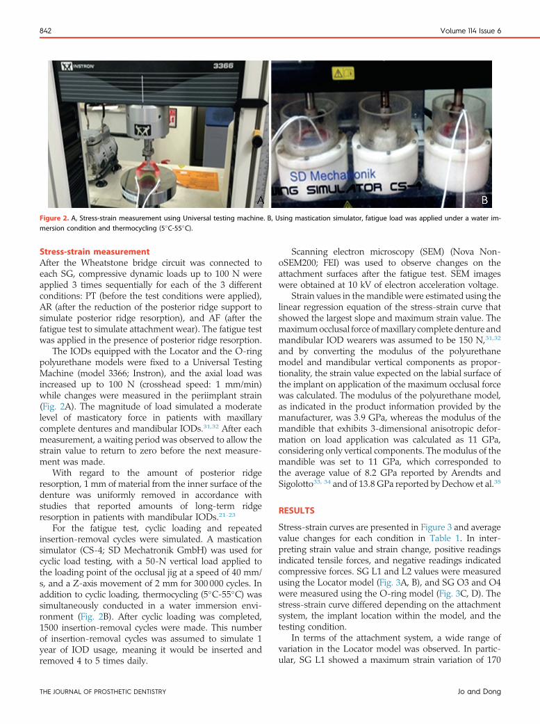
Figure 2. A, Stress-strain measurement using Universal testing machine. B, Using mastication simulator, fatigue load was applied under a water im-mersion condition and thermocycling (5�C-55�C).
842 Volume 114 Issue 6
Stress-strain measurementAfter the Wheatstone bridge circuit was connected toeach SG, compressive dynamic loads up to 100 N wereapplied 3 times sequentially for each of the 3 differentconditions: PT (before the test conditions were applied),AR (after the reduction of the posterior ridge support tosimulate posterior ridge resorption), and AF (after thefatigue test to simulate attachment wear). The fatigue testwas applied in the presence of posterior ridge resorption.
The IODs equipped with the Locator and the O-ringpolyurethane models were fixed to a Universal TestingMachine (model 3366; Instron), and the axial load wasincreased up to 100 N (crosshead speed: 1 mm/min)while changes were measured in the periimplant strain(Fig. 2A). The magnitude of load simulated a moderatelevel of masticatory force in patients with maxillarycomplete dentures and mandibular IODs.31,32 After eachmeasurement, a waiting period was observed to allow thestrain value to return to zero before the next measure-ment was made.
With regard to the amount of posterior ridgeresorption, 1 mm of material from the inner surface of thedenture was uniformly removed in accordance withstudies that reported amounts of long-term ridgeresorption in patients with mandibular IODs.21-23
For the fatigue test, cyclic loading and repeatedinsertion-removal cycles were simulated. A masticationsimulator (CS-4; SD Mechatronik GmbH) was used forcyclic load testing, with a 50-N vertical load applied tothe loading point of the occlusal jig at a speed of 40 mm/s, and a Z-axis movement of 2 mm for 300 000 cycles. Inaddition to cyclic loading, thermocycling (5�C-55�C) wassimultaneously conducted in a water immersion envi-ronment (Fig. 2B). After cyclic loading was completed,1500 insertion-removal cycles were made. This numberof insertion-removal cycles was assumed to simulate 1year of IOD usage, meaning it would be inserted andremoved 4 to 5 times daily.
THE JOURNAL OF PROSTHETIC DENTISTRY
Scanning electron microscopy (SEM) (Nova Non-oSEM200; FEI) was used to observe changes on theattachment surfaces after the fatigue test. SEM imageswere obtained at 10 kV of electron acceleration voltage.
Strain values in the mandible were estimated using thelinear regression equation of the stress-strain curve thatshowed the largest slope and maximum strain value. Themaximumocclusal force ofmaxillary complete denture andmandibular IOD wearers was assumed to be 150 N,31,32
and by converting the modulus of the polyurethanemodel and mandibular vertical components as propor-tionality, the strain value expected on the labial surface ofthe implant on application of the maximum occlusal forcewas calculated. The modulus of the polyurethane model,as indicated in the product information provided by themanufacturer, was 3.9 GPa, whereas the modulus of themandible that exhibits 3-dimensional anisotropic defor-mation on load application was calculated as 11 GPa,considering only vertical components. The modulus of themandible was set to 11 GPa, which corresponded tothe average value of 8.2 GPa reported by Arendts andSigolotto33, 34 and of 13.8 GPa reported by Dechow et al.35
RESULTS
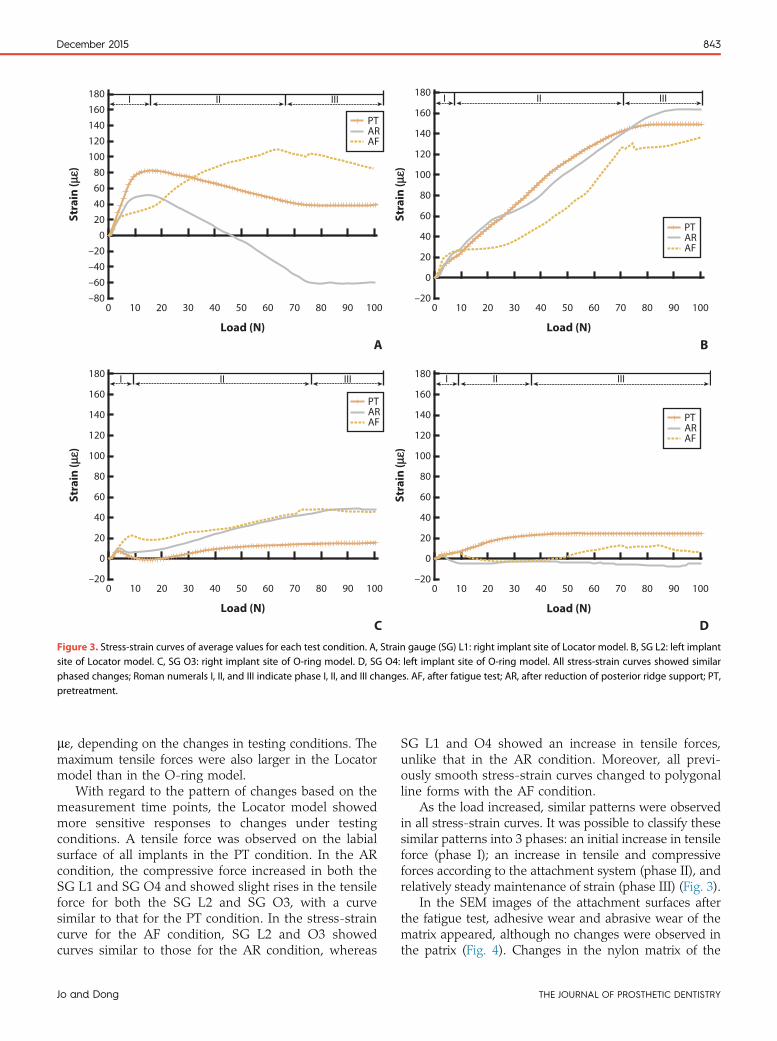
Stress-strain curves are presented in Figure 3 and averagevalue changes for each condition in Table 1. In inter-preting strain value and strain change, positive readingsindicated tensile forces, and negative readings indicatedcompressive forces. SG L1 and L2 values were measuredusing the Locator model (Fig. 3A, B), and SG O3 and O4were measured using the O-ring model (Fig. 3C, D). Thestress-strain curve differed depending on the attachmentsystem, the implant location within the model, and thetesting condition.
In terms of the attachment system, a wide range ofvariation in the Locator model was observed. In partic-ular, SG L1 showed a maximum strain variation of 170
Jo and Dong
–800 10 20 30 40 50 60 70
PTARAF
80 90 100
–60–40–20
020406080
100120140160180 I II III III III
Stra
in (μ
εμε)
Load (N)A B
C D
–200 10 20 30 40 50 60 70
PTARAF
80 90 100
0
180
160
140
120
100
80
60
40
20
Stra
in (μ
εμε)
Load (N)
–200 10 20 30 40 50 60 70
PTARAF
80 90 100
0
20
40
60
80
100
120
140
160
180 I II III III III
Stra
in (μ
εμε)
Load (N)
–200 10 20 30 40 50 60 70
PTARAF
80 90 100
0
180
160
140
120
100
80
60
40
20
Stra
in (μ
εμε)
Load (N)
Figure 3. Stress-strain curves of average values for each test condition. A, Strain gauge (SG) L1: right implant site of Locator model. B, SG L2: left implantsite of Locator model. C, SG O3: right implant site of O-ring model. D, SG O4: left implant site of O-ring model. All stress-strain curves showed similarphased changes; Roman numerals I, II, and III indicate phase I, II, and III changes. AF, after fatigue test; AR, after reduction of posterior ridge support; PT,pretreatment.
December 2015 843
mε, depending on the changes in testing conditions. Themaximum tensile forces were also larger in the Locatormodel than in the O-ring model.
With regard to the pattern of changes based on themeasurement time points, the Locator model showedmore sensitive responses to changes under testingconditions. A tensile force was observed on the labialsurface of all implants in the PT condition. In the ARcondition, the compressive force increased in both theSG L1 and SG O4 and showed slight rises in the tensileforce for both the SG L2 and SG O3, with a curvesimilar to that for the PT condition. In the stress-straincurve for the AF condition, SG L2 and O3 showedcurves similar to those for the AR condition, whereas
Jo and Dong
SG L1 and O4 showed an increase in tensile forces,unlike that in the AR condition. Moreover, all previ-ously smooth stress-strain curves changed to polygonalline forms with the AF condition.
As the load increased, similar patterns were observedin all stress-strain curves. It was possible to classify thesesimilar patterns into 3 phases: an initial increase in tensileforce (phase I); an increase in tensile and compressiveforces according to the attachment system (phase II), andrelatively steady maintenance of strain (phase III) (Fig. 3).
In the SEM images of the attachment surfaces afterthe fatigue test, adhesive wear and abrasive wear of thematrix appeared, although no changes were observed inthe patrix (Fig. 4). Changes in the nylon matrix of the
THE JOURNAL OF PROSTHETIC DENTISTRY
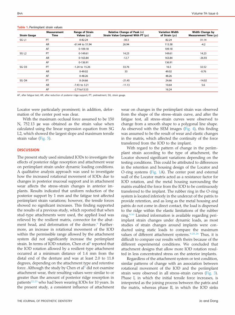
Table 1. Periimplant strain values
Strain GaugeMeasurement
TimeRange of Strain
Values (m 3)Relative Change of Peak (+)
Strain Value Compared With PT (m 3)Variation Widthof Strain (m 3)
Width Change byMeasurement Time (m 3)
SG L1 PT 0-82.24 -30.3 82.24 31.14
AR -61.44 to 51.94 26.94 113.38 -4.2
AF 0-109.18 109.18
SG L2 PT 0-149.61 14.23 149.61 14.23
AR 0-163.84 -12.7 163.84 -26.93
AF 0-136.91 136.91
SG O3 PT -1.24 to 15.26 33.76 16.5 32.52
AR 0-49.02 33 49.02 -0.76
AF 0-48.26 48.26
SG O4 PT 0-24.66 -21.45 24.66 -14.02
AR -7.43 to 3.21 -11.13 10.64 5.6
AF -2.71to13.53 16.24
AF, after fatigue test; AR, after reduction of posterior ridge support; PT, pretreatment; SG, strain gauge.
844 Volume 114 Issue 6
Locator were particularly prominent; in addition, defor-mation of the center post was clear.
With the maximum occlusal force assumed to be 150N, 752.13 mε was obtained as the strain value whencalculated using the linear regression equation from SGL2, which showed the largest slope and maximum tensilestrain value (Fig. 5).
DISCUSSION
The present study used simulated IODs to investigate theeffects of posterior ridge resorption and attachment wearon periimplant strain under dynamic loading conditions.A qualitative analysis approach was used to investigatehow the increased rotational movement of IODs due tochanges in posterior mucosal support and in attachmentwear affects the stress-strain changes in anterior im-plants. Results indicated that uniform reduction of theposterior support by 1 mm and the fatigue test affectedperiimplant strain variations; however, the tensile forcesshowed no significant increases. This finding supportedthe results of a previous study, which reported that whenstud-type attachments were used, the applied load wasrelieved by the resilient matrix, connector for the abut-ment head, and deformation of the denture.9 Further-more, an increase in rotational movement of the IODwithin the permissible range allowed by the attachmentsystem did not significantly increase the periimplantstrain. In terms of IOD rotation, Chen et al5 reported thatthe IOD rotation allowed by a resilient-type attachmentoccurred at a minimum distance of 1.4 mm from thedistal end of the denture and was at least 2.0 to 11.8degrees, depending on the attachment type and retentiveforce. Although the study by Chen et al5 did not examineattachment wear, their resulting values were similar to orgreater than the amount of posterior ridge resorption inpatients22,23 who had been wearing IODs for 10 years. Inthe present study, a consistent influence of attachment
THE JOURNAL OF PROSTHETIC DENTISTRY
wear on changes in the periimplant strain was observedfrom the shape of the stress-strain curve, and after thefatigue test, all stress-strain curves were observed tochange from a smooth shape to a polygonal line shape.As observed with the SEM images (Fig. 4), this findingwas assumed to be the result of wear and elastic changesin the matrix, which affected the continuity of the forcetransferred from the IOD to the implant.
With regard to the pattern of change in the periim-plant strain according to the type of attachment, theLocator showed significant variations depending on thetesting conditions. This could be attributed to differencesin the retention and housing design of the Locator andO-ring systems (Fig. 1A). The center post and externalwall of the Locator matrix acted as a resistance factor forIOD rotation, and the metal housing surrounding thematrix enabled the force from the IOD to be continuouslytransferred to the implant. The rubber ring in the O-ringsystem is located inferiorly in the undercut of the patrix toprovide retention, and as long as the metal housing andpatrix do not come in direct contact, the load is dispersedto the ridge within the elastic limitations of the rubberring.9,10 Limited information is available regarding peri-implant strain changes under dynamic loads, as moststudies of strain changes around implants were con-ducted using static loads to compare the maximumvalues of different attachment systems.9,25,26 Thus, it isdifficult to compare our results with theirs because of thedifferent experimental conditions. We concluded thatattachment designs that allow more IOD rotation resul-ted in less concentrated stress on the anterior implants.
Regardless of the attachment system or test condition,similar patterns of change with an association betweenrotational movement of the IOD and the periimplantstrain were observed in all stress-strain curves (Fig. 3).Phase I, in which the initial tensile force increases, isinterpreted as the joining process between the patrix andthe matrix, whereas phase II, in which the IOD sinks
Jo and Dong
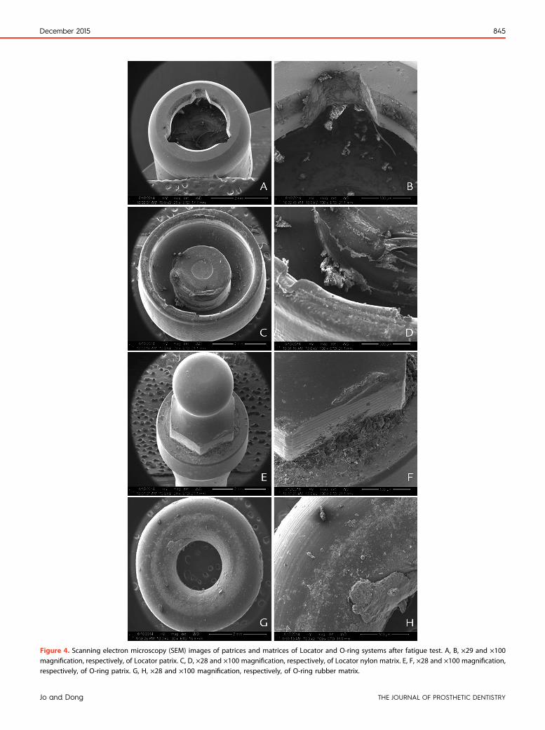
Figure 4. Scanning electron microscopy (SEM) images of patrices and matrices of Locator and O-ring systems after fatigue test. A, B, ×29 and ×100magnification, respectively, of Locator patrix. C, D, ×28 and ×100 magnification, respectively, of Locator nylon matrix. E, F, ×28 and ×100 magnification,respectively, of O-ring patrix. G, H, ×28 and ×100 magnification, respectively, of O-ring rubber matrix.
December 2015 845
Jo and Dong THE JOURNAL OF PROSTHETIC DENTISTRY

–500 10 20 30 40 50 60 70 80 90 100
0
50
100
150
y = 1.682x + 14.364
AR
200
Stra
in (μ
εμε)
Load (N)
Figure 5. Linear regression equation for strain gauge (SG) L2 afterreduction of posterior ridge support (AR).
846 Volume 114 Issue 6
after the matrix is completely seated, is interpreted as thephase with various patterns based on the attachment’sdesign and elasticity5 and mucosal thickness and elas-ticity.6,12 Phase III, in which the strain is maintained withrelatively consistent values, is the phase in which theattachment’s elasticity and mucosal displacement areexceeded; therefore, it is viewed as the phase in whichthe load increases while the rotational movement of thedenture stops at the end point. However, unlike themeasurements obtained when the mandibular modelwas firmly fixed on a flat surface, the actual mandiblewould be expected to show strain variations differentfrom those in phase (III) because of mandibular torsion.
In the present study, because a strain experiment on ahuman participant was ethically impossible, the strain thatwould be created on the mandibular labial surface wasestimated after assuming a maximum occlusal force of 150N in a maxillary complete denture and patients with amandibular IOD.31,32 The strain value obtained by usingthe linear regression equation for SG L2, which showedthe largest slope and maximum tensile strain value, was752.13 mε. Frost36 indicated that strain is generated in thebone cells from the stress exerted on the bone and that,depending on the degree of deformation, an increase inbone density or fatigue failure can occur. Furthermore, therange of bone deformation under a general load corre-sponded to 50 to 1500 mε.37 Although the value calculatedusing the regression equation for SG L2 falls within thebone deformation range of 50 to 1500 mε under a generalload, it is expected to be different from that for actual teethwhen the tendency of the mandible to show anisotropicdeformation under an applied stress is taken into consid-eration.35 Because of the nature of the strain experiment,which showed significant differences depending onexperimental conditions, comparison of the strain valuesmay be unreasonable. However, according to a study that
THE JOURNAL OF PROSTHETIC DENTISTRY
connected a stud attachment to an implant placed in themandible of a human cadaver and applied a static load of100N to the IOD tomeasure the strain in the labial surfaceof the implant, an average of −463 to −777 mε wasmeasured from the implant’s labial surface ridge,depending on the loading point.8 Because a ball andmetalsocket attachment was used in that particular study andthe strain was measured in a cadaver, the decreasedelasticity of the mucosa may have been an influencingfactor for the (−) measurement value.
The present study has limitations. The attachmentwear and residual ridge resorption factors could notcompletely replicate clinical situations, and simple com-parisons using SGswere difficult, as SGmeasurements aresensitive to testing conditions. Even though the same SGswere placed in the same locations, standardizing the re-sults between the differentmodelswas difficult.Moreover,this study aimed to analyze the changes of strain underdynamic loading conditions by simulating the rotationalmovement of IODs, and that was why we limited thenumber of models for each set-up. However, we feel theresults of this in vitro study are significant because weattempted to investigate the effects of ridge resorption andattachment wear on periimplant strain in mandibularIODs. Our results suggested clinical implications thatwhen a resilient attachment system is used, such asLocator andO-ring, a slight posterior ridge resorption andattachment wear may not cause a significant increase inperiimplant strain. From a clinical perspective, these re-sults may serve as experimental evidence for maintainingthe marginal bone height for implants15,16 and long-termimplant survival rates17,18 in mandibular IOD wearers.However, for patients who have recently become eden-tulous, during which extensive posterior ridge resorptionoccurs, the decrease in posterior mucosal support wouldhave a larger influence on tension distribution around theimplant. Even though the results of this in vitro study didnot indicate considerable biomechanical effects on theimplants, regular recall and relining of IODs could reduceperiimplant strain and attachment wear. Furthermore,because increased masticatory performance in patientswith IODs2,3 may accelerate ridge resorption,38 carefulassessments of changes in mucosal support for IODwearers who show frequent retention loss may also berequired.
To know the effects of the increased rotationalmovement on IOD derived from posterior ridgeresorption and attachment wear on the anterior im-plants, further clinical studies are needed to investigatethe effects over various time periods. Because of theethical limitations in conducting stress-strain analysesin live patients, a finite element analysis combinedwith 3D rendering using cone-beam computed to-mography seems to be an appropriate model for clin-ical research.
Jo and Dong

December 2015 847
CONCLUSIONS
The conclusions derived from the results of the presentstudy are as follows:
1. The pattern of changes in stress around the implantduring functional movements of the mandibularIOD varied according to attachment type.
2. When the Locator andO-ring attachmentswere used,approximately 1 mm of vertical posterior ridgeresorption and attachment wear did not affect the in-crease in strainon the labial surfaceareaof the implant.
3. Attachment wear affected the transfer of stress fromthe IOD to the implant, which also affected theshape of the stress-strain curve.
4. Among the attachment components used in theexperiment, the Locator matrix showed the largestdeformation during the fatigue test, which affectedthe strain variations based on an increased load.
REFERENCES
1. Thomason JM, Kelly SA, Bendkowski A, Ellis JS. Two implant retainedoverdenturesda review of the literature supporting the McGill and Yorkconsensus statements. J Dent 2012;40:22-34.
2. Muller F, Duvernay E, Loup A, Vazquez L, Herrmann FR, Schimmel M.Implant-supported mandibular overdentures in very old adults: a random-ized controlled trial. J Dent Res 2013;92:154s-60s.
3. Fontijn-Tekamp FA, Slagter AP, van’t Hof MA, Geertman ME, Kalk W. Biteforces with mandibular implant-retained overdentures. J Dent Res 1998;77:1832-9.
4. Misch CE. Dental implant prosthetics. 2nd ed. St. Louis: Mosby; 2014. p. 597.5. Chen IC, Brudvik JS, Mancl LA, Rubenstein JE, Chitswe K, Raigrodski AJ.
Freedom of rotation of selected overdenture attachments: an in vitro study.J Prosthet Dent 2011;106:78-86.
6. Haruta A, Matsushita Y, Tsukiyama Y, Sawae Y, Sakai N, Koyano K. Effects ofmucosal thickness on the stress distribution and denture stability ofmandibular implant-supported overdentures with unsplinted attachmentsin vitro. J Dent Biomech 2011;2011:894395.
7. Mericske-Stern R, Piotti M, Sirtes G. 3-D in vivo force measurements onmandibular implants supporting overdentures. A comparative study. ClinOral Implants Res 1996;7:387-96.
8. Akca K, Akkocaoglu M, Comert A, Tekdemir I, Cehreli MC. Bone strainsaround immediately loaded implants supporting mandibular overdentures inhuman cadavers. Int J Oral Maxillofac Implants 2007;22:101-9.
9. Tokuhisa M, Matsushita Y, Koyano K. In vitro study of a mandibularimplant overdenture retained with ball, magnet, or bar attachments:comparison of load transfer and denture stability. Int J Prosthodont2003;16:128-34.
10. Machado AC, Cardoso L, Brandt WC, Henriques GE, de Arruda Nobilo MA.Photoelastic analysis of the distribution of stress in different systems ofoverdentures on osseous-integrated implants. J Craniofac Surg 2011;22:2332-6.
11. Assuncao WG, Tabata LF, Barao VA, Rocha EP. Comparison of stress dis-tribution between complete denture and implant-retained overdenture-2DFEA. J Oral Rehabil 2008;35:766-74.
12. Assuncao WG, Barao VA, Tabata LF, de Sousa EA, Gomes EA, Delben JA.Comparison between complete denture and implant-retained overdenture:effect of different mucosa thickness and resiliency on stress distribution.Gerodontology 2009;26:273-81.
13. Chaffee NR, Felton DA, Cooper LF, Palmqvist U, Smith R. Prosthetic com-plications in an implant-retained mandibular overdenture population: initialanalysis of a prospective study. J Prosthet Dent 2002;87:40-4.
14. Goodacre CJ, Bernal G, Rungcharassaeng K, Kan JY. Clinical complica-tions with implants and implant prostheses. J Prosthet Dent 2003;90:121-32.
15. Cehreli MC, Karasoy D, Kokat AM, Akca K, Eckert S. A systematic review ofmarginal bone loss around implants retaining or supporting overdentures. IntJ Oral Maxillofac Implants 2010;25:266-77.
Jo and Dong
16. Vercruyssen M, Quirynen M. Long-term, retrospective evaluation (implantand patient-centred outcome) of the two-implant-supported overdenture inthe mandible. Part 2: Marginal bone loss. Clin Oral Implants Res 2010;21:466-72.
17. Rentsch-Kollar A, Huber S, Mericske-Stern R. Mandibular implant over-dentures followed for over 10 years: patient compliance and prostheticmaintenance. Int J Prosthodont 2010;23:91-8.
18. Vercruyssen M, Marcelis K, Coucke W, Naert I, Quirynen M. Long-term,retrospective evaluation (implant and patient-centred outcome) of the two-implants-supported overdenture in the mandible. Part 1: Survival rate. ClinOral Implants Res 2010;21:357-65.
19. Jacobs R, Schotte A, van Steenberghe D, Quirynen M, Naert I. Posterior jawbone resorption in osseointegrated implant-supported overdentures. ClinOral Implants Res 1992;3:63-70.
20. Wright PS, Glantz PO, Randow K, Watson RM. The effects of fixed andremovable implant-stabilised prostheses on posterior mandibular residualridge resorption. Clin Oral Implants Res 2002;13:169-74.
21. Kordatzis K, Wright PS, Meijer HJ. Posterior mandibular residual ridgeresorption in patients with conventional dentures and implant overdentures.Int J Oral Maxillofac Implants 2003;18:447-52.
22. de Jong MH, Wright PS, Meijer HJ, Tymstra N. Posterior mandibular residualridge resorption in patients with overdentures supported by two or fourendosseous implants in a 10-year prospective comparative study. Int J OralMaxillofac Implants 2010;25:1168-74.
23. Raedel M, Lazarek-Scholz K, Marre B, Boening KW, Walter MH. Posterioralveolar ridge resorption in bar-retained mandibular overdentures: 10-yearresults of a prospective clinical trial. Clin Oral Implants Res. http://dx.doi.org/10.1111/clr.12393.
24. Alsabeeha NH, Payne AG, Swain MV. Attachment systems for mandibulartwo-implant overdentures: a review of in vitro investigations on retentionand wear features. Int J Prosthodont 2009;22:429-40.
25. Porter JA Jr, Petropoulos VC, Brunski JB. Comparison of load distribution forimplant overdenture attachments. Int J Oral Maxillofac Implants 2002;17:651-62.
26. Takeshiata S, Kanazawa M, Minakuchi S. Stress analysis of mandibular two-implant overdenture with different attachment systems. Dent Mater J2011;30:928-34.
27. Carr AB, Brown DT. McCracken’s removable partial prosthodontics. 12th ed.St. Louis: Mosby; 2010. p. 253-67.
28. Sawada A, Wakabayashi N, Ona M, Suzuki T. Viscoelasticity of human oralmucosa: implications for masticatory biomechanics. J Dent Res 2011;90:590-5.
29. Misch CE. Dental implant prosthetics. 2nd ed. St. Louis: Mosby; 2014. p. 357.30. Isidor F. Influence of forces on peri-implant bone. Clin Oral Implants Res
2006;17(suppl 2):8-18.31. Geckili O, Mumcu E, Bilhan H. The effect of maximum bite force, implant
number, and attachment type on marginal bone loss around implants sup-porting mandibular overdentures: a retrospective study. Clin Implant DentRelat Res 2012;14(suppl 1):e91-7.
32. Bilhan H, Geckili O, Mumcu E, Cilingir A, Bozdag E. The influence of implantnumber and attachment type on maximum bite force of mandibular over-dentures: a retrospective study. Gerodontology 2012;29:e116-20.
33. Arendts FJ, Sigolotto C. Standard measurements, elasticity values and tensilestrength behavior of the human mandible, a contribution to the biome-chanics of the mandible-I. Biomed Tech (Berl) 1989;34:248-55.
34. Arendts FJ, Sigolotto C. Mechanical characteristics of the human mandibleand study of in vivo behavior of compact bone tissue, a contribution to thedescription of biomechanics of the mandible-II. Biomed Tech (Berl) 1990;35:123-30.
35. Dechow PC, Nail GA, Schwartz-Dabney CL, Ashman RB. Elastic propertiesof human supraorbital and mandibular bone. Am J Phys Anthropol 1993;90:291-306.
36. Frost HM. Perspectives: bone’s mechanical usage windows. Bone Miner1992;19:257-71.
37. Frost HM. A 2003 update of bone physiology and Wolff’s Law for clinicians.Angle Orthod 2004;74:3-15.
38. Kelsey CC. Alveolar bone resorption under complete dentures. J ProsthetDent 1971;25:152-61.
Corresponding author:Dr Jin-Keun DongWonkwang University460 Iksandae-roIksan 570-749REPUBLIC OF KOREAEmail: [email protected]
Copyright © 2015 by the Editorial Council for The Journal of Prosthetic Dentistry.
THE JOURNAL OF PROSTHETIC DENTISTRY


![Alveolar Ridge Preservation after Tooth Extraction Using ... · ridge resorption rate and bone remodelling after tooth extraction [15]. Autogenous bone as bone graft material is still](https://img.pdfslide.net/doc/110x75/5ed57c6a0bd3843450408daa/alveolar-ridge-preservation-after-tooth-extraction-using-ridge-resorption-rate.jpg)
![DimensionalRidgePreservationwithaNovelHighlyPorousTiO2 ...downloads.hindawi.com/journals/ijbm/2012/851264.pdfresidual ridge resorption [13]. Several experimental and clinical studies](https://img.pdfslide.net/doc/110x75/5f897322d2498872132f30f5/dimensionalridgepreservationwithanovelhighlyporoustio2-residual-ridge-resorption.jpg)