Embed Size (px)
Citation preview
Effects of reflections on TE-wave
measurements of electron cloud density
Kenneth HammondMentors: John Sikora and Kiran Sonnad
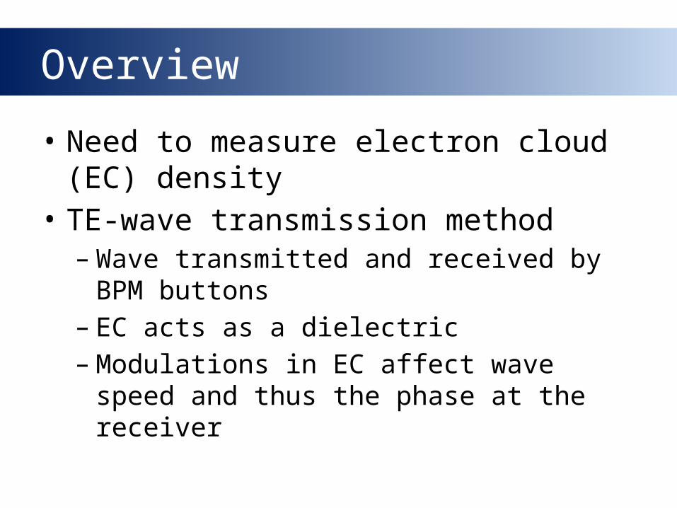
Overview
• Need to measure electron cloud (EC) density
• TE-wave transmission method–Wave transmitted and received by BPM
buttons– EC acts as a dielectric–Modulations in EC affect wave speed
and thus the phase at the receiver
Overview
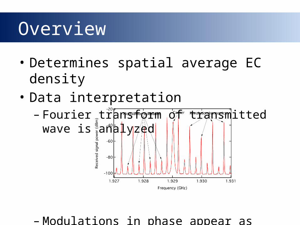
• Determines spatial average EC density
• Data interpretation– Fourier transform of transmitted wave
is analyzed
–Modulations in phase appear as frequency sidebands
Overview
• Challenges– Irregular beam pipe geometry• Cross-section makes theoretical modeling
difficult• Numerical simulation is necessary
– Amplitude modulation• Can occur in the presence of constant
magnetic fields
– Reflections• Primarily due to changes in cross-sectional
geometry• Can greatly affect average phase advance
Overview
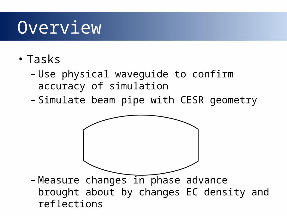
• Tasks–Use physical waveguide to confirm
accuracy of simulation– Simulate beam pipe with CESR geometry
–Measure changes in phase advance brought about by changes EC density and reflections
The Physics of Waveguides
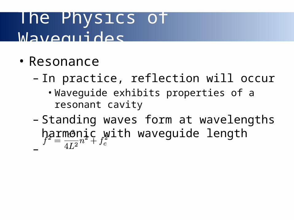
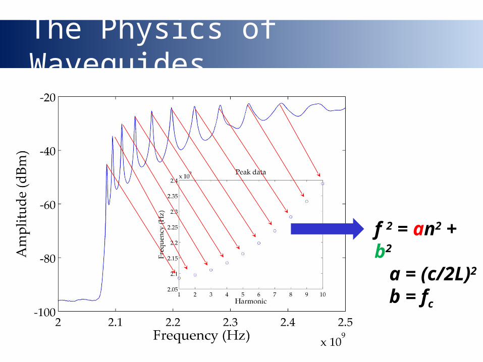
• Resonance– In practice, reflection will occur • Waveguide exhibits properties of a resonant
cavity
– Standing waves form at wavelengths harmonic with waveguide length
–
The Physics of Waveguides
f 2 = an2 + b2
a = (c/2L)2
b = fc
The Physics of Waveguides
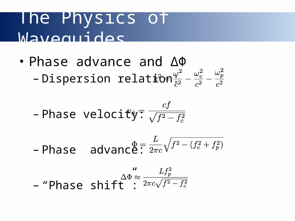
• Phase advance and ΔΦ– Dispersion relation:
– Phase velocity:
– Phase advance:
– “Phase shift”:
Simulation
• VORPAL software models waveguide system numerically
• Input boundary conditions– Conductor walls– Transmitting antenna
• Solve Maxwell’s Equations
Simulation
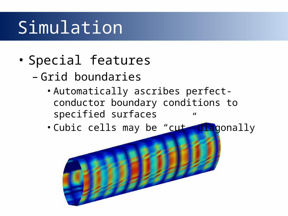
• Special features– Grid boundaries• Automatically ascribes perfect-conductor
boundary conditions to specified surfaces• Cubic cells may be “cut” diagonally
Simulation
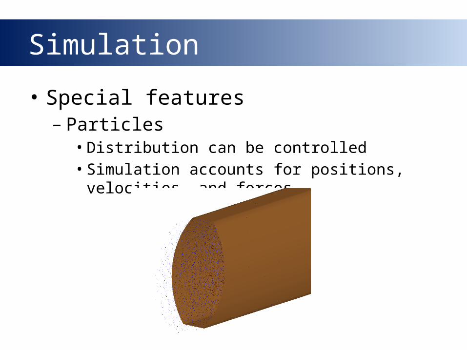
• Special features– Particles• Distribution can be controlled• Simulation accounts for positions,
velocities, and forces
Simulation
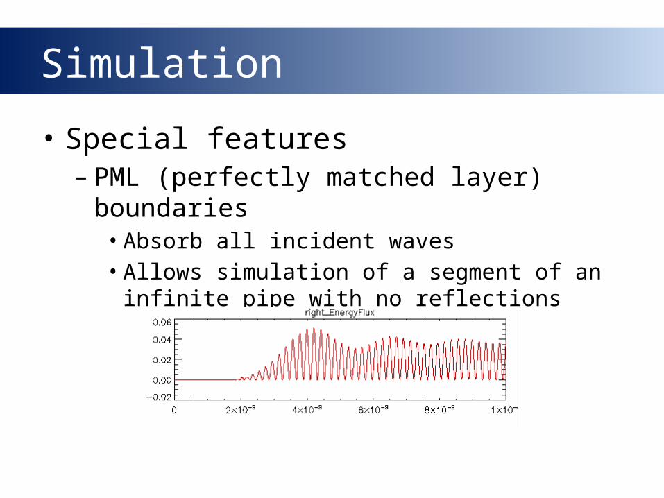
• Special features– PML (perfectly matched layer)
boundaries• Absorb all incident waves• Allows simulation of a segment of an infinite
pipe with no reflections
Simulation
• Differences with physical measurements– Time scale• Most simulations modeled the system for
70ns• Longer simulations exhibit roundoff error• Frequency sweeps are not practical
Experiments
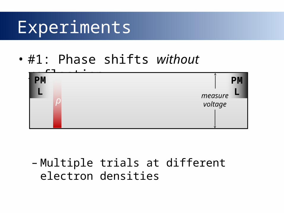
• #1: Phase shifts without reflection
–Multiple trials at different electron densities
PML
PMLρ
measure voltage
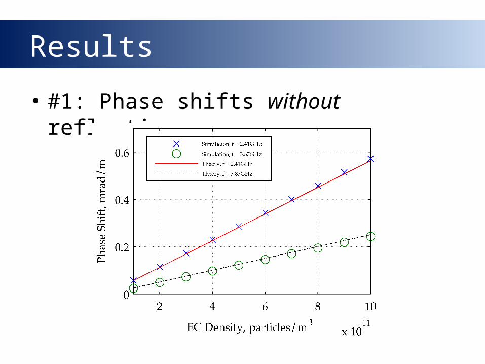
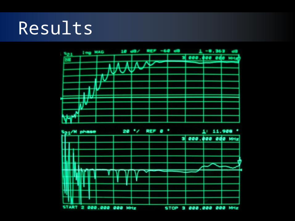
Results
• #1: Phase shifts without reflection
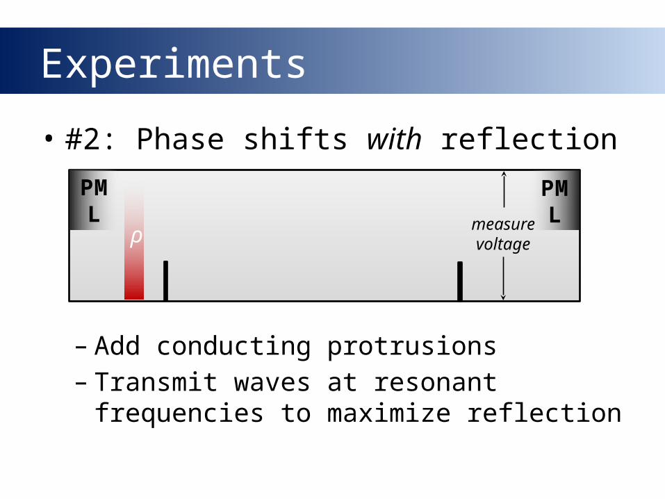
Experiments
• #2: Phase shifts with reflection
– Add conducting protrusions– Transmit waves at resonant frequencies
to maximize reflection
PML
PMLρ
measure voltage
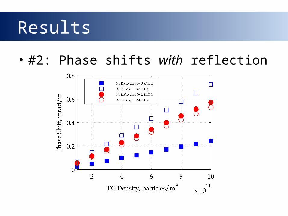
Results
• #2: Phase shifts with reflection
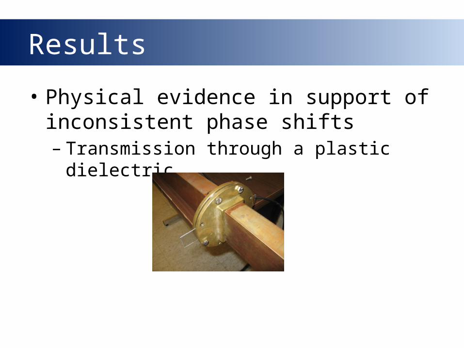
Results
• Physical evidence in support of inconsistent phase shifts– Transmission through a plastic
dielectric
Results
So, what next?
• Simulate phase shifts at more frequencies
• Streamline the method for extracting phase shift
• Study phase shifts for different electron cloud distributions

Acknowledgments
Special thanks to
John Sikora
Kiran Sonnad
Seth Veitzer

Effects of reflections on TE-wave
measurements of electron cloud density
Kenneth HammondMentors: John Sikora and Kiran Sonnad
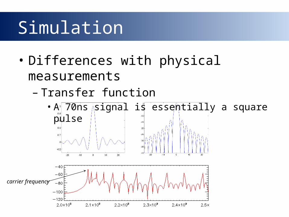
Simulation
• Differences with physical measurements– Transfer function• A 70ns signal is essentially a square pulse
carrier frequency
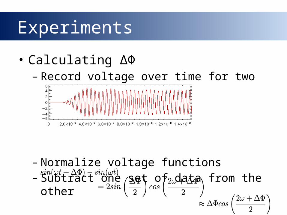
Experiments
• Calculating ΔΦ– Record voltage over time for two
simulations
–Normalize voltage functions– Subtract one set of data from the other

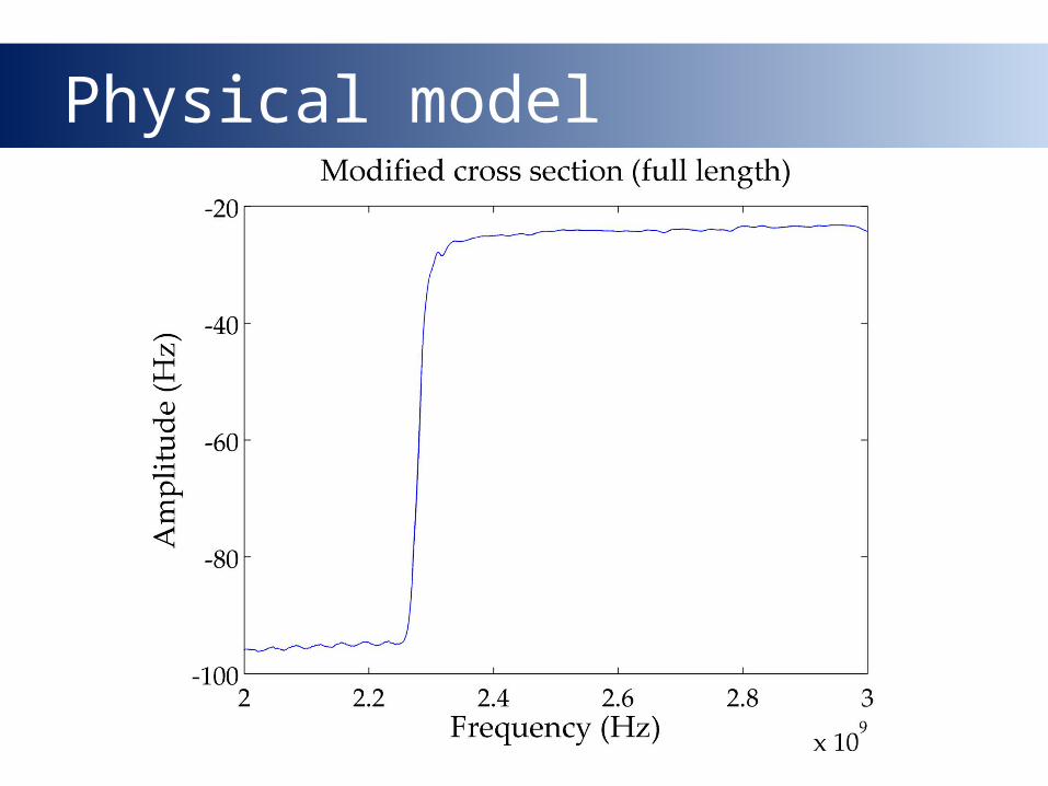
Physical model
Pipe length: l = 1.219m
Flange walls: l = 1.329m Optimized length: 1.281m
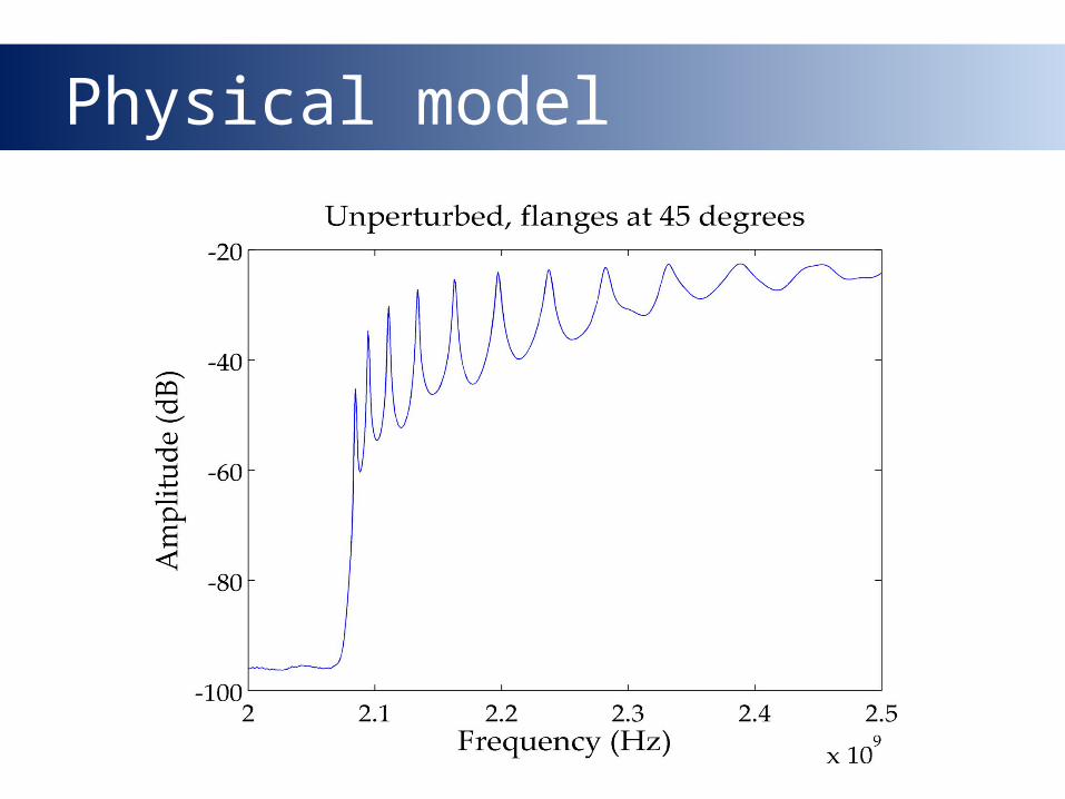
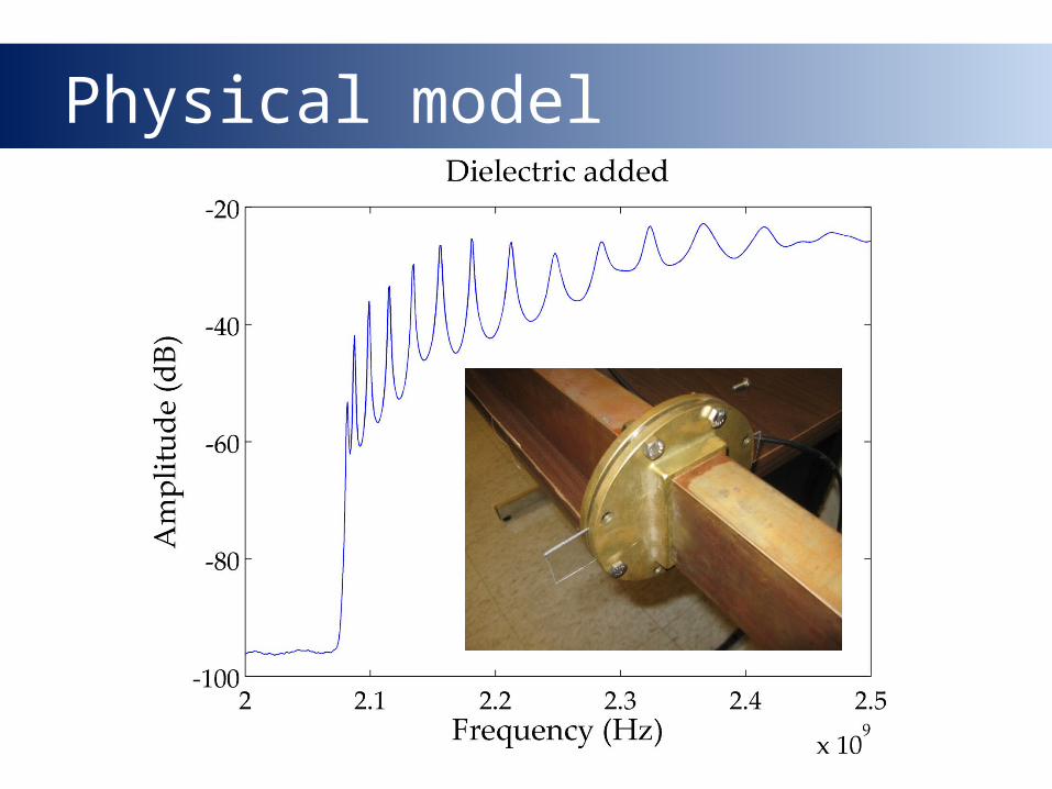
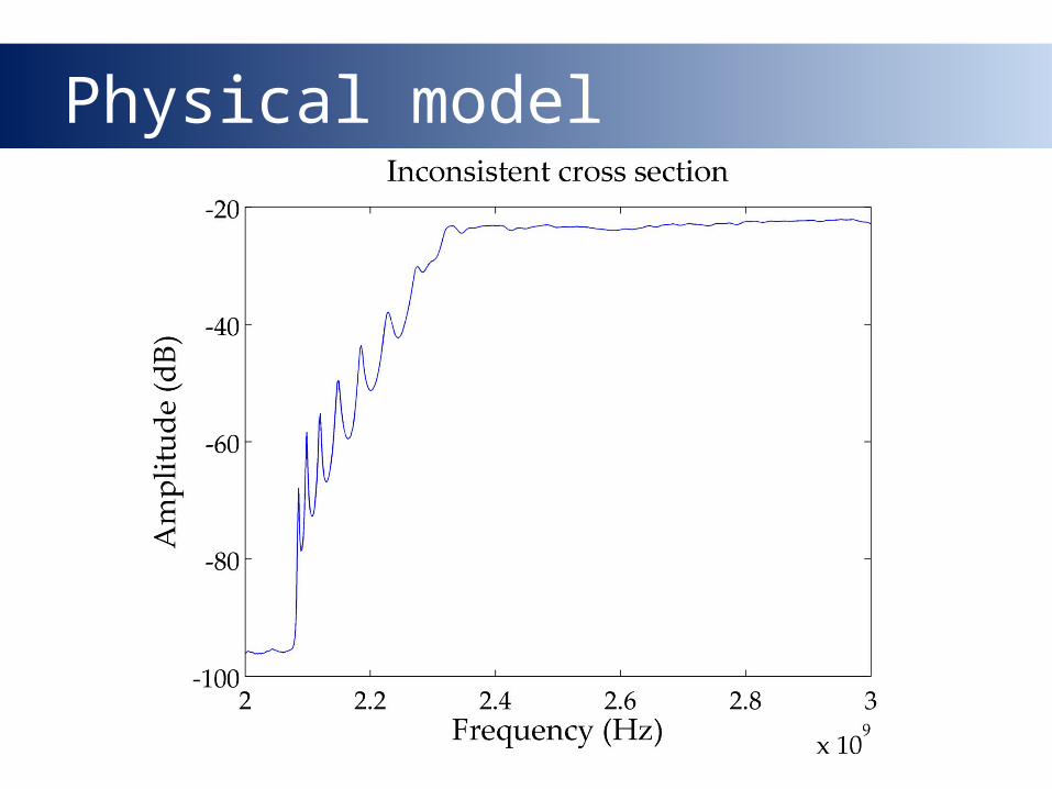
Physical model

Physical model
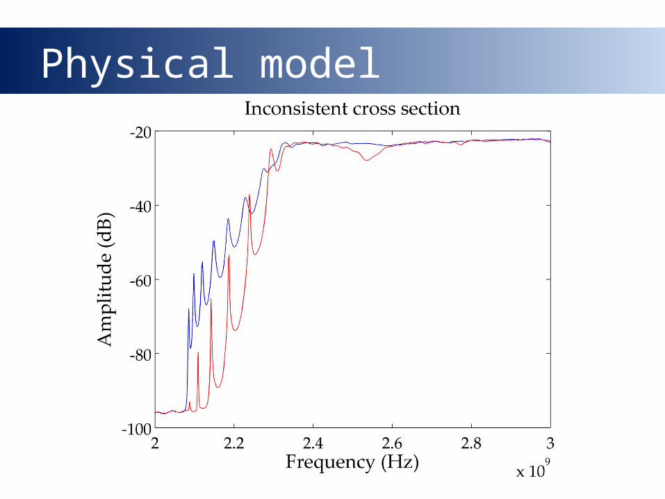
Physical model
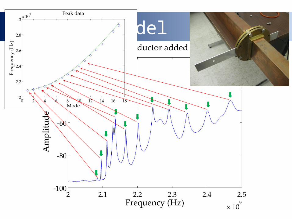
Physical model
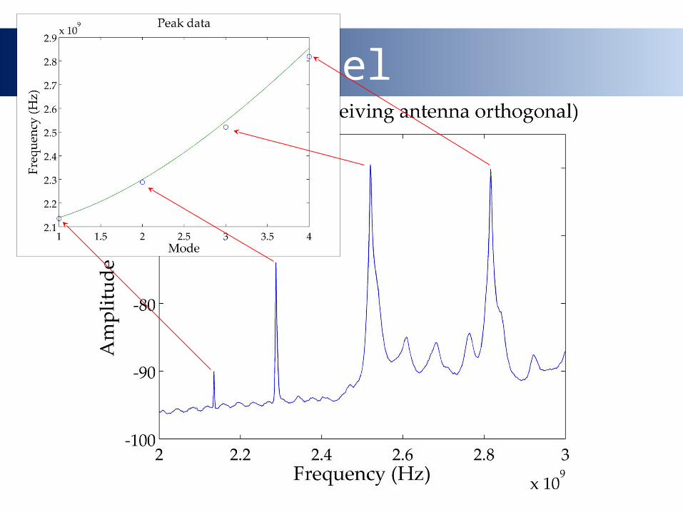
Physical model
Physical model
Physical model
Physical model
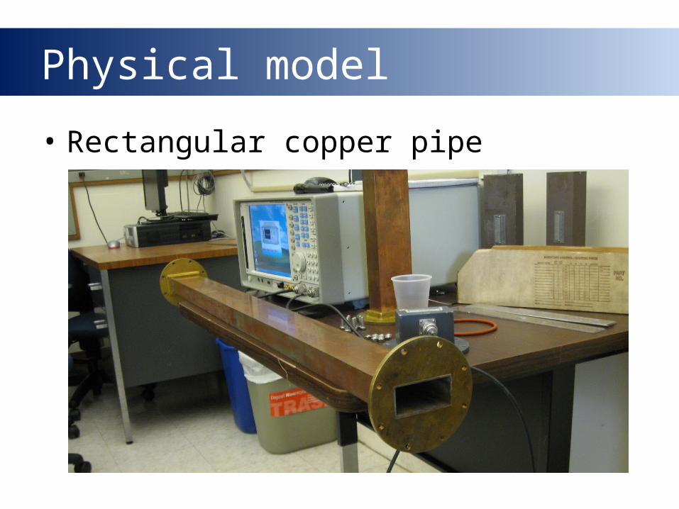
Physical model
• Rectangular copper pipe

The Physics of Waveguides
• Waveguide: a hollow metal pipe
• Facilitates efficient RF energy transfer
• Cutoff frequency: minimum frequency required for transmission– Determined by cross-sectional geometry