Embed Size (px)
Citation preview
Effects of Soil-Forming Processes on Cover Engineering Properties, Field Work Plan Bluewater Disposal Site, New Mexico February 2016
LMS/BLU/S13276

This page intentionally left blank
U.S. Department of Energy Effects of Soil-Forming Processes on Cover Engineering Properties, Field Work Plan—Bluewater February 2016 Doc. No. S13276 Page i
Contents Abbreviations ................................................................................................................................. iii 1.0 Introduction and Work Flow ..................................................................................................1
1.1 Purpose and Scope .......................................................................................................1 1.2 Field Work Flow ..........................................................................................................4
1.2.1 Equipment and Materials Required .............................................................4 1.2.2 Locate Test Sites ..........................................................................................4 1.2.3 Remove Riprap Cover at Designated Locations (LMS Team) .....................7 1.2.4 Excavate to Remove Layers Overlying the Radon Barrier if
Applicable (LMS Team) ...............................................................................7 1.2.5 Radon Flux Measurements on Surface of Radon Barrier
(Research Group) .........................................................................................7 1.2.6 Large Block Sampling (Research Group) ...................................................8 1.2.7 Sampling With Thin-Wall Sampling Tubes (Research Group) ..................8 1.2.8 Perform Soil Morphology Sampling (Research Group) ............................10 1.2.9 Radon Flux Measurements on Surface of Tailings (Research Group) ......10 1.2.10 Repair the Radon Barrier (LMS Team, Geotechnical Subcontractor) .......13 1.2.11 Radon Flux Measurements on Repaired Radon Barrier (LMS Team) .......13 1.2.12 Replace Rock Riprap and Demobilization (LMS Team) ............................13
2.0 Potential Dose ......................................................................................................................13 2.1 Radon Exposure .........................................................................................................13 2.2 Thorium and Radium Exposure .................................................................................14
3.0 Safety and Health .................................................................................................................15 3.1 Job Safety Analysis ...................................................................................................15 3.2 Training Requirements ..............................................................................................15 3.3 First Aid/CPR ............................................................................................................16 3.4 Personal Protective Equipment Within the Work Zone ............................................16 3.5 Sanitation ...................................................................................................................16 3.6 Drinking Water ..........................................................................................................16 3.7 Lightning ...................................................................................................................16 3.8 Excavations ................................................................................................................17 3.9 Safety Data Sheets .....................................................................................................17 3.10 Electrical Safety .........................................................................................................17 3.11 Radioactive Sources ..................................................................................................17 3.12 Dosimetry ..................................................................................................................17
4.0 Environmental Management System ...................................................................................18 4.1 Waste Management ...................................................................................................18
4.1.1 Waste Reduction and Recycling ................................................................19 4.2 Spills ..........................................................................................................................19 4.3 Cultural Resources .....................................................................................................19 4.4 Migratory Bird Treaty Act .........................................................................................19 4.5 Endangered Species Act ............................................................................................19
5.0 References ............................................................................................................................20
Effects of Soil-Forming Processes on Cover Engineering Properties, Field Work Plan—Bluewater U.S. Department of Energy Doc. No. S13276 February 2016 Page ii
Figures Figure 1. Vicinity Map of Bluewater .............................................................................................. 2 Figure 2. Potential Test Locations .................................................................................................. 5 Figure 3. Photos of Large and Small Flux Chambers ..................................................................... 9 Figure 4. Proposed Sampling Layout............................................................................................ 11
Appendixes Appendix A Long-Term Cover Performance Projects Technical Task Plan - Section 4:
Project 1: Effects of Soil-Forming Processes on Cover Engineering Properties Appendix B Bluewater Cover Design and Construction Review
U.S. Department of Energy Effects of Soil-Forming Processes on Cover Engineering Properties, Field Work Plan—Bluewater February 2016 Doc. No. S13276 Page iii
Abbreviations ALARA As Low As Reasonably Achievable
AS&T Applied Studies and Technology
CFR Code of Federal Regulations
DOE U.S. Department of Energy
EC Environmental Compliance
ESA Endangered Species Act
JSA Job Safety Analysis
LM Office of Legacy Management
LMS Legacy Management Support
LTS&M long-term surveillance and maintenance
mrem/year milliroentgen equivalent in man per year
µR/hour microroentgen per hour
µg/m3 micrograms per cubic meter
MTP Main Tailings Pile
NEPA National Environmental Policy Act
NHPA National Historic Preservation Act
NRC U.S. Nuclear Regulatory Commission
pCi/g picocuries per gram
pCi/m2s picocuries per square meters per second
PPE personal protective equipment
SDS safety data sheet
TTP Technical Task Plan

Effects of Soil-Forming Processes on Cover Engineering Properties, Field Work Plan—Bluewater U.S. Department of Energy Doc. No. S13276 February 2016 Page iv
This page intentionally left blank
U.S. Department of Energy Effects of Soil-Forming Processes on Cover Engineering Properties, Field Work Plan—Bluewater February 2016 Doc. No. S13276 Page 1
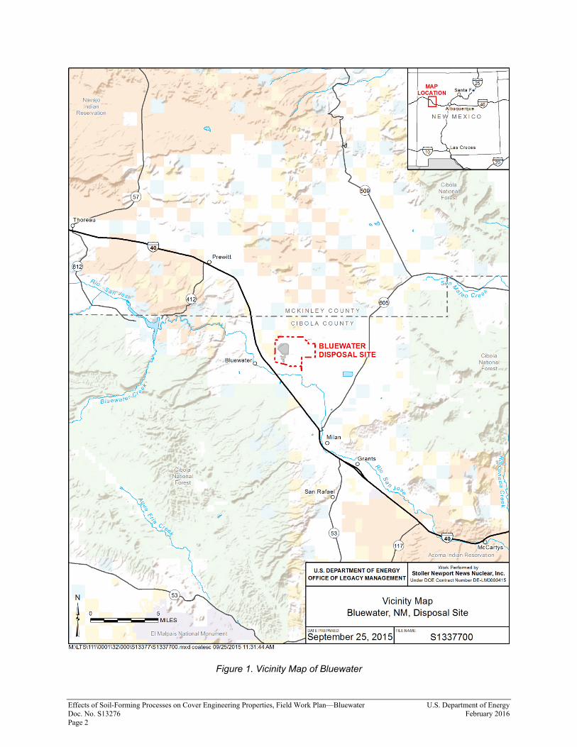
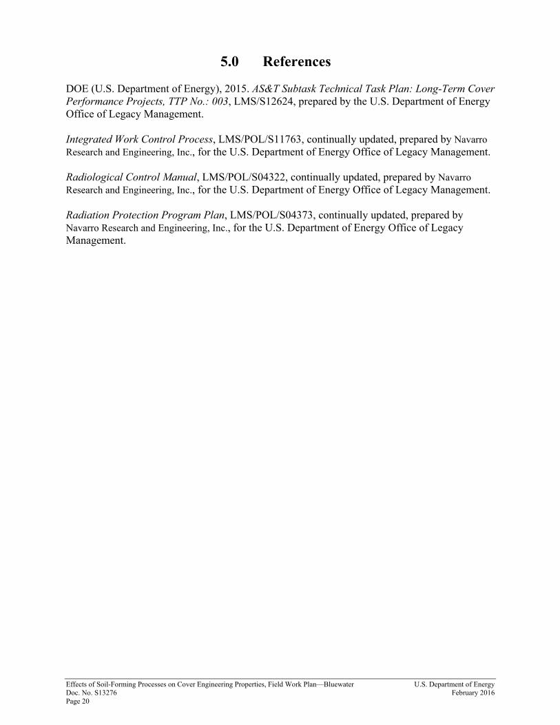
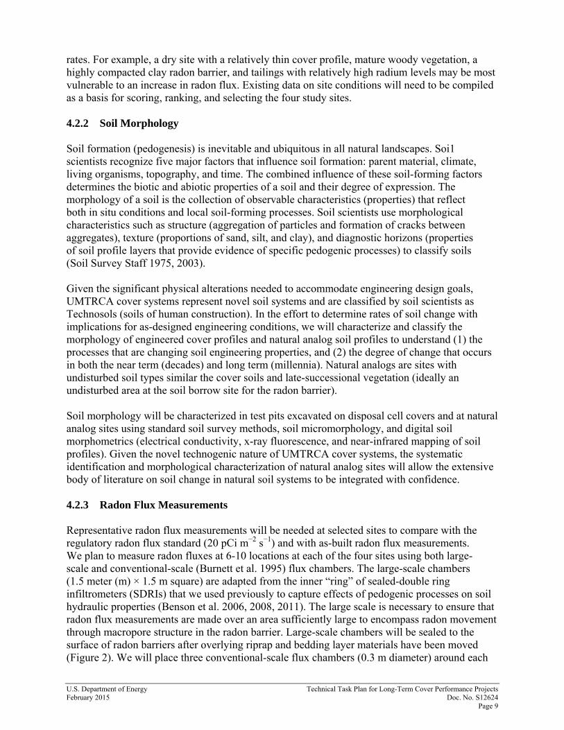
1.0 Introduction and Work Flow 1.1 Purpose and Scope Overview: This study is Project 1 in the Technical Task Plan (TTP), “Long-Term Cover Performance Projects” (DOE 2015), and is included as Appendix A of this Work Plan. The U.S. Department of Energy (DOE) Office of Legacy Management (LM) is responsible for the long-term surveillance and maintenance (LTS&M) of disposal cells for uranium mill tailings throughout the United States. The long-term protectiveness of disposal cells relies on engineered covers to limit radon releases, rainwater percolation, and erosion. Natural ecological and soil-forming processes are slowly changing the as-built engineering properties of disposal cell covers in ways that could potentially alter protectiveness and increase LTS&M costs. This study is one of four ongoing Applied Studies and Technology (AS&T) projects designed to evaluate effects of natural processes on the performance of disposal cell covers and investigate options for improving the LTS&M of covers to thereby inform LM managers as they fulfill their responsibilities to comply with applicable laws and regulations, maintain long-term protectiveness, and reduce long-term costs. For all Long-Term Cover Performance projects, we establish collaboration and cost sharing with other agencies and researchers, foster education, and disseminate new knowledge through presentations and peer-reviewed publications. The U.S. Nuclear Regulatory Commission (NRC) and LM are sharing the costs of this study. Scientists and engineers from Legacy Management Support (LMS), the University of Wisconsin, the University of California, Berkeley, and the Desert Research Institute are collaborating on the study. The study will partially fulfill the graduate school requirements for two PhD candidates. Results will be published. This project was designed to (1) characterize the morphology of disposal cell cover soils to understand the natural processes that are changing engineering properties and the degree of change over decades and millennia, (2) measure effects of soil-forming processes on gas diffusivity and soil hydraulic properties, (3) determine how changes in engineering properties vary with depth in cover profiles, and (4) measure and model how these changes influence radon flux rates and rainwater percolation. (See the TTP for a literature review regarding natural changes in the engineering properties of disposal cell covers and discussions of the relevance and objectives of the project.) Four sites that represent a range of cover types, climates, site conditions, and vulnerabilities to change will be selected for study. Relationships between soil morphology and cover engineering properties will be evaluated in test pits on covers and at natural analog sites to understand near-term and potential long-term effects of pedogenesis. In the cover test pits evaluation, methods and scales for measuring radon flux, physical properties that influence radon flux, and depth-dependent soil hydraulic properties will be evaluated. Changes in physical and hydraulic properties since construction and changes in radon flux and potential percolation rates in response to natural soil formation will then be calculated and modeled. The project is scheduled to be completed in 2018. Project collaborators selected the Bluewater, New Mexico, Disposal Site as the first test site based on the outcome of a Uranium Mill Tailings Radiation Control Act Title I and II site screening and ranking process. Figure 1 is a general vicinity map of the Bluewater disposal site.
Effects of Soil-Forming Processes on Cover Engineering Properties, Field Work Plan—Bluewater U.S. Department of Energy Doc. No. S13276 February 2016 Page 2
Figure 1. Vicinity Map of Bluewater
U.S. Department of Energy Effects of Soil-Forming Processes on Cover Engineering Properties, Field Work Plan—Bluewater February 2016 Doc. No. S13276 Page 3
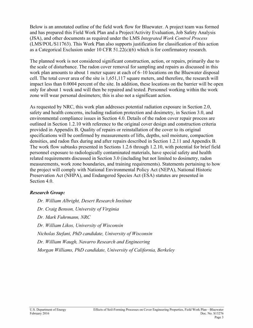
Below is an annotated outline of the field work flow for Bluewater. A project team was formed and has prepared this Field Work Plan and a Project/Activity Evaluation, Job Safety Analysis (JSA), and other documents as required under the LMS Integrated Work Control Process (LMS/POL/S11763). This Work Plan also supports justification for classification of this action as a Categorical Exclusion under 10 CFR 51.22(c)(6) which is for confirmatory research. The planned work is not considered significant construction, action, or repairs, primarily due to the scale of disturbance. The radon cover removal for sampling and repairs as discussed in this work plan amounts to about 1 meter square at each of 6–10 locations on the Bluewater disposal cell. The total cover area of the site is 1,651,117 square meters, and therefore, the research will impact less than 0.0004 percent of the site. In addition, these locations on the barrier will be open only for about 1 week and will then be repaired and tested. Personnel working within the work zone will wear personal dosimeters; this is also not a significant action. As requested by NRC, this work plan addresses potential radiation exposure in Section 2.0, safety and health concerns, including radiation protection and dosimetry, in Section 3.0, and environmental compliance issues in Section 4.0. Details of the radon cover repair process are outlined in Section 1.2.10 with reference to the original cover design and construction criteria provided in Appendix B. Quality of repairs or reinstallation of the cover to its original specifications will be confirmed by measurements of lifts, depths, soil moisture, compaction densities, and radon flux during and after repairs described in Section 1.2.11 and Appendix B. The work flow subtasks presented in Sections 1.2.6 through 1.2.10, with potential for brief field personnel exposure to radiologically contaminated materials, have special safety and health related requirements discussed in Section 3.0 (including but not limited to dosimetry, radon measurements, work zone boundaries, and training requirements). Statements pertaining to how the project will comply with National Environmental Policy Act (NEPA), National Historic Preservation Act (NHPA), and Endangered Species Act (ESA) statutes are presented in Section 4.0. Research Group:
Dr. William Albright, Desert Research Institute Dr. Craig Benson, University of Virginia Dr. Mark Fuhrmann, NRC Dr. William Likos, University of Wisconsin Nicholas Stefani, PhD candidate, University of Wisconsin Dr. William Waugh, Navarro Research and Engineering Morgan Williams, PhD candidate, University of California, Berkeley
Effects of Soil-Forming Processes on Cover Engineering Properties, Field Work Plan—Bluewater U.S. Department of Energy Doc. No. S13276 February 2016 Page 4
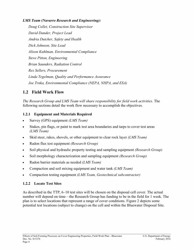
LMS Team (Navarro Research and Engineering): Doug Collet, Construction Site Supervisor David Dander, Project Lead Andria Dutcher, Safety and Health Dick Johnson, Site Lead Alison Kuhlman, Environmental Compliance Steve Pitton, Engineering Brian Saunders, Radiation Control Rex Sellers, Procurement Linda Tegelman, Quality and Performance Assurance Joe Trnka, Environmental Compliance (NEPA, NHPA, and ESA)
1.2 Field Work Flow The Research Group and LMS Team will share responsibility for field work activities. The following sections detail the work flow necessary to accomplish the objectives. 1.2.1 Equipment and Materials Required • Survey (GPS) equipment (LMS Team) • Stakes, pin flags, or paint to mark test area boundaries and tarps to cover test areas
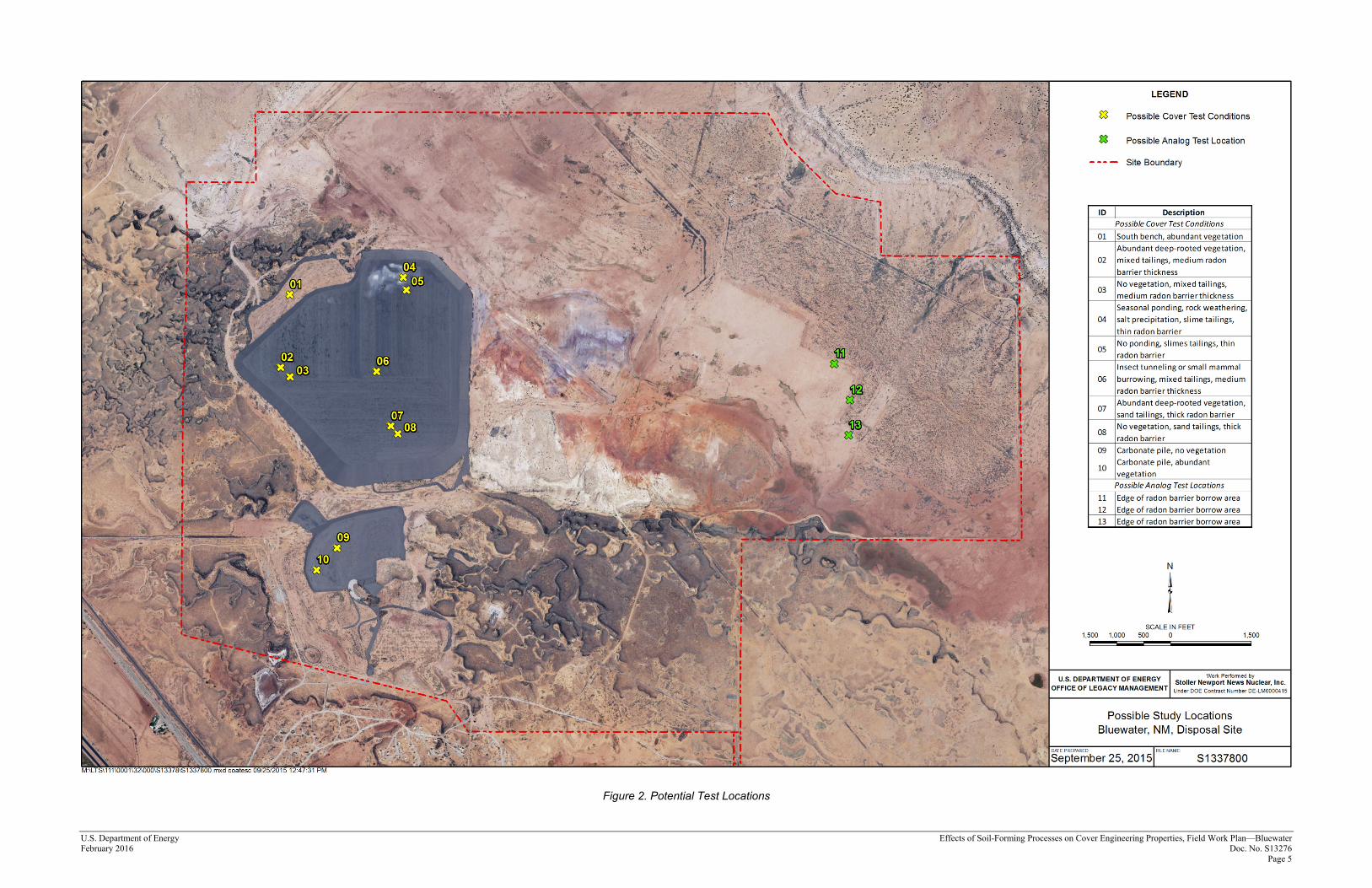
(LMS Team) • Skid steer, rakes, shovels, or other equipment to clear rock layer (LMS Team) • Radon flux test equipment (Research Group) • Soil physical and hydraulic property testing and sampling equipment (Research Group) • Soil morphology characterization and sampling equipment (Research Group) • Radon barrier materials as needed (LMS Team) • Compaction and soil mixing equipment and water tank (LMS Team) • Compaction testing equipment (LMS Team, Geotechnical subcontractor) 1.2.2 Locate Test Sites As described in the TTP, 6–10 test sites will be chosen on the disposal cell cover. The actual number will depend on time—the Research Group has funding to be in the field for 1 week. The plan is to select locations that represent a range of cover conditions. Figure 2 depicts some potential test locations (subject to change) on the cell and within the Bluewater Disposal Site.
U.S. Department of Energy Effects of Soil-Forming Processes on Cover Engineering Properties, Field Work Plan—Bluewater February 2016 Doc. No. S13276 Page 5
Figure 2. Potential Test Locations
Effects of Soil-Forming Processes on Cover Engineering Properties, Field Work Plan—Bluewater U.S. Department of Energy Doc. No. S13276 February 2016 Page 6
This page intentionally left blank
U.S. Department of Energy Effects of Soil-Forming Processes on Cover Engineering Properties, Field Work Plan—Bluewater February 2016 Doc. No. S13276 Page 7
Examples of potential test conditions*: • Areas likely to have the most pedogenesis and greatest seasonal drying (i.e., areas with
abundant vegetation rooted in the radon barrier) • Areas likely to have the least pedogenesis and least seasonal drying (i.e., areas where
ponding occurs on the surface) • Areas where tunneling insects and burrowing mammals have created channels and brought
radon-barrier material to the surface • “Typical” areas on top slope or side slope (areas not impacted by vegetation, animals or
insects, or ponded water) Subtasks: • Survey and stake the extent of the test area (LMS Team) • Record survey reading (LMS Team) 1.2.3 Remove Riprap Cover at Designated Locations (LMS Team) • Riprap will be removed, exposing the radon barrier in a 5 m × 5 m area for each test
location. Riprap will be stockpiled to be replaced at the conclusion of the sampling. • Install access and safety (depth of excavation) control, if required. This will not likely be
required at Bluewater because the excavation depth will not exceed 4 feet 11 inches. • Leave an undisturbed surface outside at least one edge. Soil morphology will be
characterized on an undisturbed cover soil profile along this edge. • Secure tarp over exposed radon barrier. The tarp is intended to limit drying of the radon
barrier (or wetting if it is raining) between the time the LMS Team removes the riprap and the Research Group begins testing.
1.2.4 Excavate to Remove Layers Overlying the Radon Barrier if Applicable
(LMS Team) This step will not be necessary at Bluewater (the cover does not have a bedding layer or protection layer). Rock riprap was placed directly over the radon barrier; however, some post cover installation windblown materials may have fallen through the riprap and will be removed at the request of the research team. 1.2.5 Radon Flux Measurements on Surface of Radon Barrier (Research Group) Radon flux on the surface of the radon barrier will be measured at each location with one large-scale (1.5 m × 1.5 m) and three small-scale (0.3 m diameter) conventional flux chambers. The large-scale chambers are adapted from the inner “ring” of sealed-double-ring infiltrometers that were used previously to measure effects of pedogenic processes on soil hydraulic properties. The large scale is necessary to ensure that radon flux measurements are made over an area sufficiently large to encompass radon movement through macropore structure (caused by soil-forming processes) in the radon barrier. Large-scale chambers will be sealed to the surface of radon barriers, and some borrow source material may be utilized. The research group will grout flux chambers to the radon-barrier surface with bentonite, attach a Teflon bag to the chamber with Teflon tubing to ensure pressure equilibrium inside and outside the chamber, and
*For each category, areas likely to have higher radium concentrations closer to the surface would be preferred. Replication of conditions 1 and 2 would be preferred.
Effects of Soil-Forming Processes on Cover Engineering Properties, Field Work Plan—Bluewater U.S. Department of Energy Doc. No. S13276 February 2016 Page 8
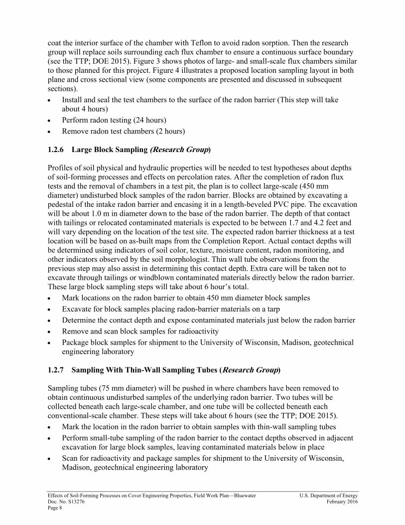
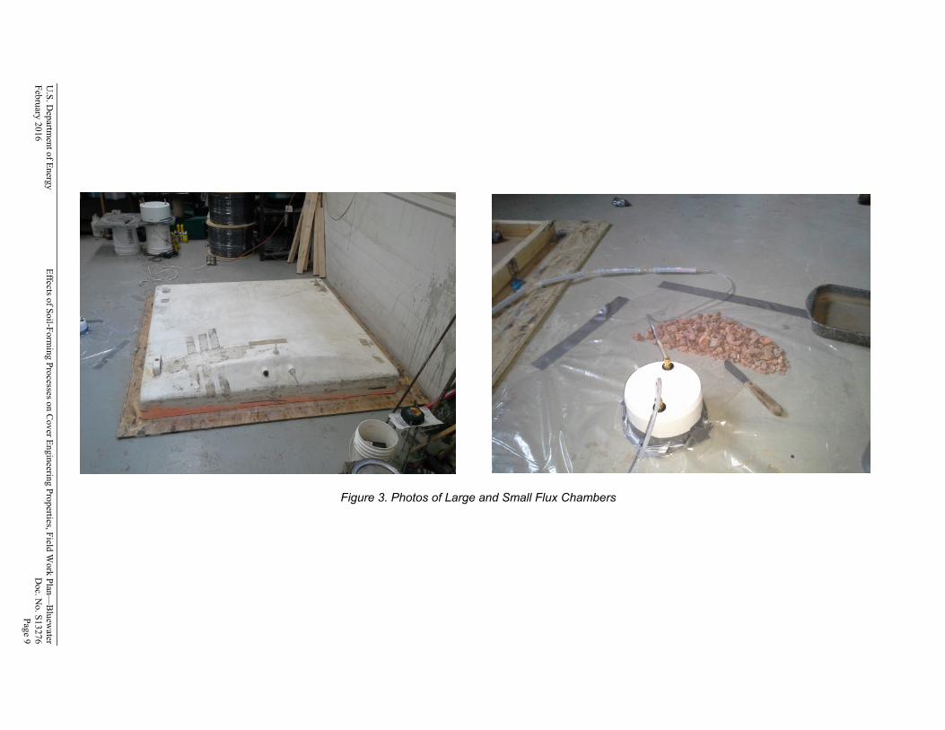
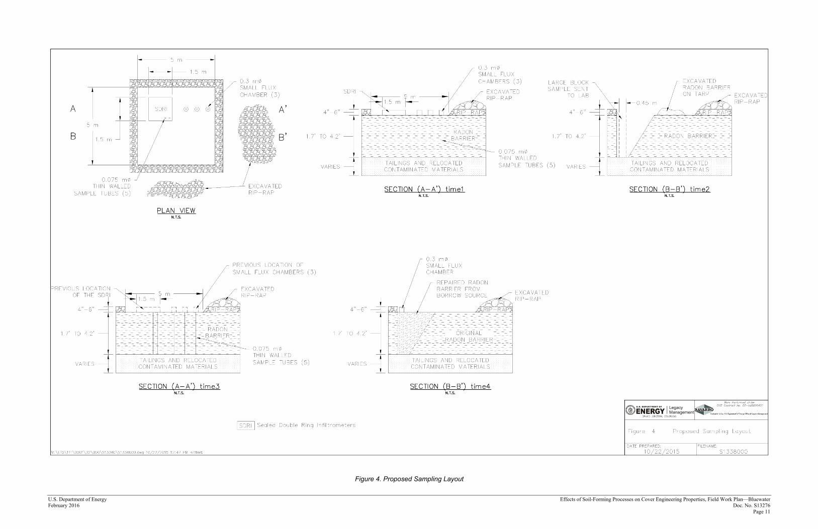
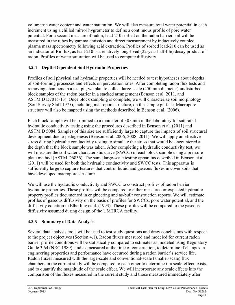
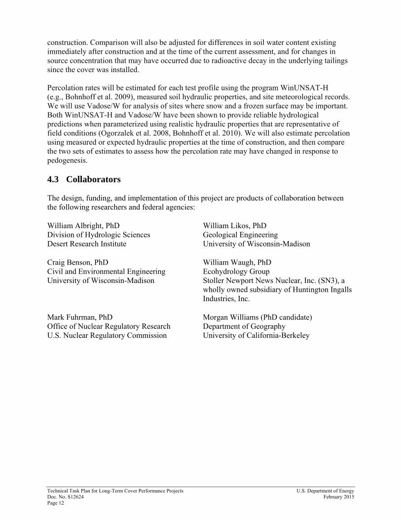
coat the interior surface of the chamber with Teflon to avoid radon sorption. Then the research group will replace soils surrounding each flux chamber to ensure a continuous surface boundary (see the TTP; DOE 2015). Figure 3 shows photos of large- and small-scale flux chambers similar to those planned for this project. Figure 4 illustrates a proposed location sampling layout in both plane and cross sectional view (some components are presented and discussed in subsequent sections). • Install and seal the test chambers to the surface of the radon barrier (This step will take
about 4 hours) • Perform radon testing (24 hours) • Remove radon test chambers (2 hours) 1.2.6 Large Block Sampling (Research Group) Profiles of soil physical and hydraulic properties will be needed to test hypotheses about depths of soil-forming processes and effects on percolation rates. After the completion of radon flux tests and the removal of chambers in a test pit, the plan is to collect large-scale (450 mm diameter) undisturbed block samples of the radon barrier. Blocks are obtained by excavating a pedestal of the intake radon barrier and encasing it in a length-beveled PVC pipe. The excavation will be about 1.0 m in diameter down to the base of the radon barrier. The depth of that contact with tailings or relocated contaminated materials is expected to be between 1.7 and 4.2 feet and will vary depending on the location of the test site. The expected radon barrier thickness at a test location will be based on as-built maps from the Completion Report. Actual contact depths will be determined using indicators of soil color, texture, moisture content, radon monitoring, and other indicators observed by the soil morphologist. Thin wall tube observations from the previous step may also assist in determining this contact depth. Extra care will be taken not to excavate through tailings or windblown contaminated materials directly below the radon barrier. These large block sampling steps will take about 6 hour’s total. • Mark locations on the radon barrier to obtain 450 mm diameter block samples • Excavate for block samples placing radon-barrier materials on a tarp • Determine the contact depth and expose contaminated materials just below the radon barrier • Remove and scan block samples for radioactivity • Package block samples for shipment to the University of Wisconsin, Madison, geotechnical
engineering laboratory 1.2.7 Sampling With Thin-Wall Sampling Tubes (Research Group) Sampling tubes (75 mm diameter) will be pushed in where chambers have been removed to obtain continuous undisturbed samples of the underlying radon barrier. Two tubes will be collected beneath each large-scale chamber, and one tube will be collected beneath each conventional-scale chamber. These steps will take about 6 hours (see the TTP; DOE 2015). • Mark the location in the radon barrier to obtain samples with thin-wall sampling tubes • Perform small-tube sampling of the radon barrier to the contact depths observed in adjacent
excavation for large block samples, leaving contaminated materials below in place • Scan for radioactivity and package samples for shipment to the University of Wisconsin,
Madison, geotechnical engineering laboratory
U.S. D
epartment of Energy
Effects of Soil-Forming Processes on C
over Engineering Properties, Field Work Plan—
Bluew
ater February 2016
D
oc. No. S13276
Page 9
Figure 3. Photos of Large and Small Flux Chambers
Effects of Soil-Forming Processes on Cover Engineering Properties, Field Work Plan—Bluewater U.S. Department of Energy Doc. No. S13276 February 2016 Page 10
1.2.8 Perform Soil Morphology Sampling (Research Group) The plan is to characterize and classify the morphology of engineered cover profiles and natural analog soil profiles to (1) understand the pedogenic processes responsible for the development of feedbacks that may impact soil engineering properties and (2) quantify the degree of change that may occur on decade- and century-long time scales (over the design life of cover systems. The morphology of soil profiles in the cover test pits (both the rock riprap and radon-barrier layers) and at an analog site (undisturbed profiles at the radon-barrier borrow site that may occur at a future date after demobilization) will be characterized. Possible analog site locations shown in Figure 2 are also subject to change based on planned field reconnaissance and any identified environmental conditions. Characterization will include conventional soil survey methods, digital soil morphometrics, thin-section micromorphology, and microbial community assay/nutrient cycling. The morphology of analog soil profiles will provide clues as to how soil-forming processes may continue to change the cover in the long term (100s to 1000s of years). Within cover test pits, a clean, undisturbed profile face will be exposed on a side of the block sample excavation. For analog soil characterization, a cut face at the edge of the radon-barrier borrow area will be cleaned to expose undisturbed soil profiles. Roughly the volume of a 5-gallon bucket of cover materials will be removed from each cut face for chemical, physical, and biological analysis. Soil morphology characterization and sampling will take about 4 hours per soil profile.
• Hand dig clean profile faces along undisturbed edges of the 1 m diameter excavations where block samples were removed and on cut faces of the radon-barrier borrow area
• Characterize morphology, and take morphometric measurements
• Retrieve samples for chemical, physical, and biological analysis
• Package samples for shipment to the University of California, Berkeley, soil morphology laboratory
1.2.9 Radon Flux Measurements on Surface of Tailings (Research Group) After soil morphology sampling is complete, radon flux will be measured within the 1.0 m diameter block sample excavation at the surface of the tailings (or in the layer immediately below the radon barrier, which is most often low-activity soil) using a small-scale conventional flux chamber. • Install and seal test chamber at each site
• Perform radon testing
• Remove radon test chamber
U.S. Department of Energy Effects of Soil-Forming Processes on Cover Engineering Properties, Field Work Plan—Bluewater February 2016 Doc. No. S13276 Page 11
Figure 4. Proposed Sampling Layout
Effects of Soil-Forming Processes on Cover Engineering Properties, Field Work Plan—Bluewater U.S. Department of Energy Doc. No. S13276 February 2016 Page 12
This page intentionally left blank
U.S. Department of Energy Effects of Soil-Forming Processes on Cover Engineering Properties, Field Work Plan—Bluewater February 2016 Doc. No. S13276 Page 13
1.2.10 Repair the Radon Barrier (LMS Team, Geotechnical Subcontractor) The radon barrier will be restored to the original designed condition presented in Appendix B. Soil will be retrieved from the radon-barrier borrow area at the Bluewater site to supplement material set aside from the excavation. Radon-barrier materials will be replaced to meet the original design specifications for moisture and compaction. Compaction will be in 6-inch lifts, achieved with a flat-plate hand compactor and tested using a moisture/density gauge. Radon-barrier repairs will be monitored for moisture and compaction requirements by a geotechnical subcontractor during material placement.
• Acquire radon-barrier soil from borrow area
• Moisture-condition radon barrier soils; the use of a mixer may be necessary
• Rebuild radon barrier in test pit meeting as-designed lift height and compaction
• Test compaction with a moisture/density gauge (geotechnical subcontract) 1.2.11 Radon Flux Measurements on Repaired Radon Barrier (LMS Team) After radon-barrier repair is complete, radon flux will again be measured (using same procedures described in Section 1.1.5) above the former 1.0 m diameter block sample excavation using a small-scale conventional flux chamber. • Install and seal test chamber at each site
• Perform post repair radon testing
• Remove radon test chamber 1.2.12 Replace Rock Riprap and Demobilization (LMS Team) The previously removed rock riprap layer will be restored to the original designed condition.
• Reinstall riprap cover meeting the as-designed thickness
• Demobilize equipment
2.0 Potential Dose 2.1 Radon Exposure The Completion Report for Reclamation of the Bluewater Mill Site, dated March 1996, Section 7.1 states: “Radon flux verification was made at 125 evenly spaced locations on [top of the radon barrier of] the Main Tailings Pile (MTP). A gamma ray exposure rate measurement was made at each point. The measured radon flux value for each of the measurement points was below the limit with an average of 2.8 picocuries per square meters per second (pCi/m2s). This clearly shows that the flux measurements are in compliance with the standard of 20 pCi/m2s.” DOE regulation 10 CFR 835 contains several requirements involving occupational exposure to radon and radon progeny that proved impractical to implement. The major problem was that the regulation presumed that it would be practical to distinguish occupational exposure to radon and
Effects of Soil-Forming Processes on Cover Engineering Properties, Field Work Plan—Bluewater U.S. Department of Energy Doc. No. S13276 February 2016 Page 14
radon progeny from background exposure to the same radionuclides. Several provisions of the regulation involved record keeping and the triggering of additional measurements based on this presumption. In practice, it proved impractical to separately measure occupational exposures and background. Therefore, the DOE granted an exemption from several radon-related provisions of 10 CFR 835 on February 9, 1995. The exemption eliminated the need to attempt to separately measure occupational exposures and background. In the future, background and occupational exposures will be combined, and the exemption raises thresholds beyond which certain monitoring and air sampling is required. However, during LMS projects similar to this Bluewater sampling, radon monitoring was conducted using track etch dosimeters. Based on these air samples, it has been determined that remedial actions for uranium mill tailings present little potential for measurable internal radon exposure. Although the DOE radon dose exemption provides relief from inherent problems with radon dose assessment, DOE is committed to keeping individual and collective doses As Low As Reasonably Achievable (ALARA) using the following concepts: Time: reducing the time spent in a radiological area Distance: increasing the distance between an individual and the radiation source Shielding: increasing the amount of shielding around a radiation source LMS will also implement practical radiological controls which will include real-time radiological dose monitoring, established physical boundaries, posting of signs identifying area-specific hazards, monitoring for loose contamination levels, dust suppression, area access control, and personal protective equipment (PPE) appropriate for the work being conducted. 2.2 Thorium and Radium Exposure In order to be conservative, we can assume that the main work over the tailings pile with the radon barrier removed would result in an average 70 picocuries per gram (pCi/g) of Th-230 (this is far greater than any measurement we have recorded in previous mill tailings disposal cells). The most exposed worker would be the operator working right at the point of penetration. Let’s assume they work for approximately 40 hours (this calculation is compared against the allowable limits based on a yearly exposure). An exposure pathway for this worker would be gamma radiation exposure from Th-230 and Ra-226 contaminated soils. Measurements have shown that the gamma exposure rate ranges from 0.5 to 2.0 microroentgen per hour (µR/hour) - per pCi/g. Note also that these measurements are very conservative. Also note that although µR and µrem are two different measurements, for gamma rays the units are considered equivalent; 1 µR is equal to 1 µrem. Taking the maximum value for a 40-hour exposure time (averaged over a year) would result in an increase of 5.6 milliroentgen equivalent in man per year (mrem/year) for that worker. This is extremely conservative as the exposure time will be significantly less than 40 hours. In addition, during construction of the disposal facility, less-contaminated material was placed on top of the more contaminated tailings. Therefore, once the exploratory hole is created the exposure rate is expected to be considerably less than 70 pCi/g. To ensure we maintain exposure ALARA, all activities with the potential for radiological exposure will be continuously monitored by a certified DOE Radiological Control Technician.
U.S. Department of Energy Effects of Soil-Forming Processes on Cover Engineering Properties, Field Work Plan—Bluewater February 2016 Doc. No. S13276 Page 15
Another pathway that may be considered for the worker is the intake of contaminated soils by inhalation. A dusty work environment would normally result in less than 200 micrograms per cubic meter (µg/m3) of respirable dust. Assuming a breathing rate of 20 liters per minute, a Th-230 concentration of 70 pCi/g, a Ra-226 concentration of 25 pCi/g, and an exposure time of 40 hours per year, the worker would be expected to receive a committed Effective Dose Equivalent of approximately 0.2 mrem/year (the annual limit for occupational radiation workers is 5000 mrem/year). Factors used for assessment for Committed Dose Equivalent per unit intake via inhalation were taken from the Health Physics and Radiological Health Handbook. Therefore, no significant radiological risks are associated with this work activity. However, all work will be monitored and recorded to ensure ALARA principals are enforced.
3.0 Safety and Health This section describes the project safety and health requirements. All work shall be conducted in accordance with safety regulations promulgated by the U.S. Department of Energy, and state and local agencies. Workers are responsible for identifying safety concerns, potential hazards, or unsafe conditions and notifying management. Each worker has the right, responsibility, and authority to report unsafe or environmentally unsound conditions or practices and stop work activities without fear of reprisal. Unsafe workers, including workers who do not wear any required personal protective equipment (PPE), will be required to leave the site. 3.1 Job Safety Analysis All LMS Team workers shall adhere to the hazard controls specified in the approved JSA. Workers shall not perform any work not covered by the JSA or for which the JSA does not provide adequate protection. The contractor Safety and Health representative can modify the JSA to reflect changed conditions or equipment as needed or as requested by a worker. 3.2 Training Requirements Workers are responsible for performing tasks in accordance with provided training and may not perform tasks for which they have not been adequately trained. Minimum training requirements include the following:
• Initial Site Briefing: All field personnel shall attend an initial site briefing lead by the LMS Team on the first day of work before conducting any field work. If circumstances require the use of personnel who did not attend the initial site briefing, these personnel will receive individual briefings from the LMS Team before they may begin field work.
• Tailgate Safety Meetings: At the beginning of each day’s work and before specific tasks with significant or changed safety considerations, the LMS Team will conduct an operations safety and health meeting for all personnel. The scope of the upcoming day’s operations and activities will be reviewed, and hazards associated with those activities will be identified along with the safety implications and procedures to mitigate the hazards. Relevant safety documentation associated with the upcoming work will be reviewed. In addition, issues or
Effects of Soil-Forming Processes on Cover Engineering Properties, Field Work Plan—Bluewater U.S. Department of Energy Doc. No. S13276 February 2016 Page 16
concerns noted from the previous days’ activities will be discussed. This briefing will be documented to identify the topics discussed and personnel in attendance.
• Radiological Worker Level II Training: Workers performing or supporting excavation work have the potential to contact low-level radiological contamination in the disposal cell. These personnel shall be required to successfully complete Radiological Worker Level II training provided by the LMS Team. Workers who do not have Radiological Worker Level II Training will not be allowed to perform or support excavation work until they get that training. Workers should plan for this training to take up to 10 hours, and the training will be provided once at a location convenient to the LMS Team. The LMS Team cannot be held responsible for delays in providing the training for workers who are not present for the initial training. The LMS Team will pay for the cost of the trainer.
3.3 First Aid/CPR The LMS Team will provide a person who is trained in first aid/CPR who will be onsite at all times while work is being performed. The LMS Team will ensure that a first-aid kit is onsite at all times when workers are present. 3.4 Personal Protective Equipment Within the Work Zone The requirement for specific PPE, including when to wear it, will be determined by the LMS Team in the JSA for the project. The LMS Team reserves the right to adjust PPE requirements to protect personnel from hazards; any worker can ask to increase PPE. All personnel shall wear safety glasses with side shields or lens wrap that are stamped on the frame as meeting ANSI Z87.1, American National Standard for Occupational and Educational Eye and Face Protection Devices. Hearing protection will be required whenever noise levels preclude holding a conversation by two people standing 3 feet apart. All workers shall wear shoes with safety toes (steel or composite). 3.5 Sanitation The LMS Team will provide a chemical toilet and hand-washing station at the worksite. 3.6 Drinking Water Bottled drinking water will be provided to field crew by the LMS Team, and proper hydration will be encouraged throughout the study. 3.7 Lightning When an electrical storm is close enough to the work site to be a hazard to site employees, personnel shall seek shelter in buildings, vehicles, equipment with cabs, low areas, or ground
U.S. Department of Energy Effects of Soil-Forming Processes on Cover Engineering Properties, Field Work Plan—Bluewater February 2016 Doc. No. S13276 Page 17
depressions and remain there until the contractor authorizes the resumption of work. Arroyos and other drainages are not suitable because of the potential for flash flooding. The “flash-bang” method shall be used. The flash-bang method involves counting the time from seeing a flash of lightning to hearing the thunder. For each 5-second count, lightning is approximately 1 mile away. The flash-bang method will be used to determine if work will be halted. When the time interval is less than 30 seconds, indicating lightning within 6 miles, the site will be shut down and reassessed every 30 minutes. 3.8 Excavations Excavations shall not exceed 4 feet 11 inches in depth without proper consideration to soil types by competent person in accordance with Occupational Safety and Health Administration regulations. No excavations over 4 feet 11 inches deep are authorized for this work. A work zone will be established at each excavation location by the Safety and Health representative overseeing the study. These excavations will expose contaminated tailings or relocated contaminated materials and have limited radon exposure potential. Radiological Worker II Training discussed in Section 3.2 and dosimetry discussed in Section 3.12 will be requirements for access to the work zone along with other directions and procedures dictated by the Safety and Health representative. Non-essential personnel for this subtask will remain outside the excavation work zone and will not require personal dosimetry or Radiological Worker II training. 3.9 Safety Data Sheets The Research Group shall submit to the LMS Team a copy of the safety data sheet (SDS) for each chemical the group intends to use on the jobsite. A copy of each SDS shall be kept on the jobsite and placed in a convenient location for all personnel to access. 3.10 Electrical Safety All power tools shall be used with a ground fault circuit interrupter device. No damaged cords, spliced cords, or tools with guards removed will be allowed on the LM site. Generators shall be grounded according to manufacturer’s instructions. 3.11 Radioactive Sources Radioactive sources, including nuclear soil density gauges, shall not be brought on a jobsite without prior notification to the contractor’s Radiological Control Manager. Radioactive sources shall be identified by serial number, isotope, and the most current integrity test. 3.12 Dosimetry NRC has requested that dosimetry be considered for workers assigned to this project. In accordance with the Radiation Protection Program Plan (LMS/POL/SO4373), Section 6.3, External Dosimetry Program, the LMS Team’s objective is to keep individual radiation doses at as low as reasonably achievable levels and, in all cases, below the regulatory limits specified by 10 Code of Federal Regulations (CFR) 835. To accomplish this objective, LMS Team
Effects of Soil-Forming Processes on Cover Engineering Properties, Field Work Plan—Bluewater U.S. Department of Energy Doc. No. S13276 February 2016 Page 18
management established administrative control levels in the LMS Radiological Control Manual (LMS/POL/SO4322) that are below the regulatory limits in order to control individual and total radiation dose. The control levels are tiered, with increasing levels of authority required to exceed higher administrative control levels. Unless otherwise indicated, all administrative control levels and dose limits are stated in terms of the effective dose. Given the nature of the LMS contract and the limited potential for personnel to exceed the radiation dose monitoring thresholds specified in 10 CFR 835, personnel dosimetry is not currently used in support of the LM mission. To ensure all operations remain conservative, the requirements of 10 CFR 835 will be as described in the LMS Radiological Control Manual. The LMS Team’s radiological operations will include real-time monitoring of all radiation based activities to include, contamination control, dose determination; and decontamination if needed. The Research Group will identify certain personnel who will be issued dosimeters as a requirement of the NRC. LMS personnel are not required to wear dosimeters. External radiation doses will be determined with the use of site-issued dosimeters provided and processed by a subcontracted dosimeter service company accredited in accordance with the DOE Laboratory Accreditation Program.
4.0 Environmental Management System In accordance with the LMS Team’s Environmental, Safety and Health Policy and the Environmental Management System, all personnel performing work for LM through its LMS Team shall follow safe and environmentally sound work practices. Work shall be conducted in a manner that protects workers and the public, complies with DOE directives, and complies with applicable federal, state, and local requirements, agreements, and permits under the LM contract. In addition, work shall be conducted in a manner that prevents pollution, minimizes wastes, and conserves natural and cultural resources to the extent that such activities are technically and economically feasible. Personnel are responsible for informing the project manager of any unsafe or environmentally unsound conditions and have the authority to stop work without fear of reprisal if necessary. 4.1 Waste Management Personnel shall properly manage all nonhazardous and hazardous waste generated by project activities. The site shall be kept clean and orderly. Personnel shall clean up debris and waste material from the site daily. Construction debris and nonhazardous waste material shall be disposed of in a receptacle provided by the project lead. Personnel shall immediately notify the project lead if any hazardous waste is suspected or generated outside the scope of the project and follow the Environmental Compliance (EC) lead’s directions to manage the waste.
U.S. Department of Energy Effects of Soil-Forming Processes on Cover Engineering Properties, Field Work Plan—Bluewater February 2016 Doc. No. S13276 Page 19
4.1.1 Waste Reduction and Recycling As required by Executive Order 13423 and DOE directives, the LMS Team must meet certain waste reduction and recycling targets. In working toward these targets: • All personnel are encouraged to minimize the waste generated during projects and
maximize the amount of material that is reused, salvaged, and recycled. • All materials recycled and or disposed of shall be tracked with total volumes or weights
supplied to the project lead, who will report the totals to the EC lead. 4.2 Spills If spills of any fluids from equipment operations or maintenance (fuel, hydraulic fluids, coolant, lubricants, cleaning solvents, used oil, etc.) occur, personnel shall immediately notify the project lead, Safety and Health, and Environmental Compliance and follow their directions to clean up the spill. Equipment leaks and other types of spills shall be diapered, contained, absorbed, or otherwise blocked to prevent ground surface contamination until the leak is repaired or the equipment is replaced. Personnel shall clean up and subsequently manage spilled materials and associated wastes (e.g., contaminated soils), including proper storage, until EC can arrange for offsite disposal of the material. 4.3 Cultural Resources The majority of the work would take place on the engineered cover of the disposal site. The cover is a modern engineered feature that has no cultural resources sensitivity. Radon-cover repair materials will be obtained from previously disturbed areas within the original borrow source area next to the disposal site. Some investigations into the “analog” soil profile will take place at the edge of the borrow source area. The locations of that profile investigation will be identified by team members for survey by a professional archaeologist prior to investigation (after demobilization from the other study activities). The analog profile locations will not be disturbed until they have been found to be clear of cultural resources and the results of that survey have been communicated to NRC. 4.4 Migratory Bird Treaty Act Personnel shall not work or travel in areas outside of the approved work areas or access routes without approval. Personnel shall not harass or otherwise disturb nesting birds; remove nests, eggs, or young birds; or in any way cause a “take” to a migratory bird. 4.5 Endangered Species Act The majority of the work will take place on the engineered cover of the disposal site. The cover is a modern engineered feature that has no sensitivity with respect to biological resources. Some investigations into the soil profile will take place at the edge of the source of the radon-barrier material. This previously established borrow area has been disturbed in the past due to extraction activity and has low habitat value.
Effects of Soil-Forming Processes on Cover Engineering Properties, Field Work Plan—Bluewater U.S. Department of Energy Doc. No. S13276 February 2016 Page 20
5.0 References DOE (U.S. Department of Energy), 2015. AS&T Subtask Technical Task Plan: Long-Term Cover Performance Projects, TTP No.: 003, LMS/S12624, prepared by the U.S. Department of Energy Office of Legacy Management. Integrated Work Control Process, LMS/POL/S11763, continually updated, prepared by Navarro Research and Engineering, Inc., for the U.S. Department of Energy Office of Legacy Management. Radiological Control Manual, LMS/POL/S04322, continually updated, prepared by Navarro Research and Engineering, Inc., for the U.S. Department of Energy Office of Legacy Management. Radiation Protection Program Plan, LMS/POL/S04373, continually updated, prepared by Navarro Research and Engineering, Inc., for the U.S. Department of Energy Office of Legacy Management.
Appendix A
Long-Term Cover Performance Projects Technical Task Plan - Section 4: Project 1: Effects of Soil-Forming Processes on Cover
Engineering Properties

This page intentionally left blank
U.S. Department of Energy Technical Task Plan for Long-Term Cover Performance Projects February 2015 Doc. No. S12624 Page 7
4.0 Project 1: Effects of Soil-Forming Processes on Cover Engineering Properties
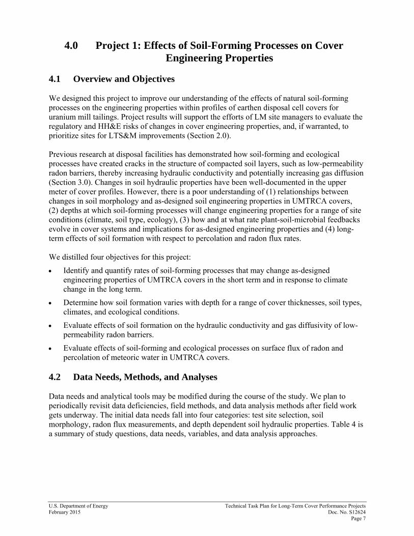
4.1 Overview and Objectives We designed this project to improve our understanding of the effects of natural soil-forming processes on the engineering properties within profiles of earthen disposal cell covers for uranium mill tailings. Project results will support the efforts of LM site managers to evaluate the regulatory and HH&E risks of changes in cover engineering properties, and, if warranted, to prioritize sites for LTS&M improvements (Section 2.0). Previous research at disposal facilities has demonstrated how soil-forming and ecological processes have created cracks in the structure of compacted soil layers, such as low-permeability radon barriers, thereby increasing hydraulic conductivity and potentially increasing gas diffusion (Section 3.0). Changes in soil hydraulic properties have been well-documented in the upper meter of cover profiles. However, there is a poor understanding of (1) relationships between changes in soil morphology and as-designed soil engineering properties in UMTRCA covers, (2) depths at which soil-forming processes will change engineering properties for a range of site conditions (climate, soil type, ecology), (3) how and at what rate plant-soil-microbial feedbacks evolve in cover systems and implications for as-designed engineering properties and (4) long-term effects of soil formation with respect to percolation and radon flux rates. We distilled four objectives for this project:
Identify and quantify rates of soil-forming processes that may change as-designed engineering properties of UMTRCA covers in the short term and in response to climate change in the long term.
Determine how soil formation varies with depth for a range of cover thicknesses, soil types, climates, and ecological conditions.
Evaluate effects of soil formation on the hydraulic conductivity and gas diffusivity of low-permeability radon barriers.
Evaluate effects of soil-forming and ecological processes on surface flux of radon and percolation of meteoric water in UMTRCA covers.
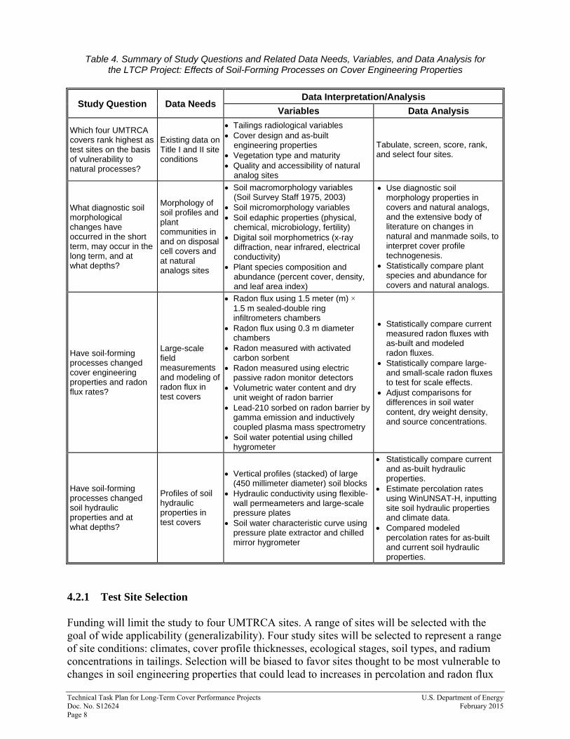
4.2 Data Needs, Methods, and Analyses Data needs and analytical tools may be modified during the course of the study. We plan to periodically revisit data deficiencies, field methods, and data analysis methods after field work gets underway. The initial data needs fall into four categories: test site selection, soil morphology, radon flux measurements, and depth dependent soil hydraulic properties. Table 4 is a summary of study questions, data needs, variables, and data analysis approaches.
Technical Task Plan for Long-Term Cover Performance Projects U.S. Department of Energy Doc. No. S12624 February 2015 Page 8
Table 4. Summary of Study Questions and Related Data Needs, Variables, and Data Analysis for the LTCP Project: Effects of Soil-Forming Processes on Cover Engineering Properties
Study Question Data Needs Data Interpretation/Analysis
Variables Data Analysis
Which four UMTRCA covers rank highest as test sites on the basis of vulnerability to natural processes?
Existing data on Title I and II site conditions
Tailings radiological variables Cover design and as-built
engineering properties Vegetation type and maturity Quality and accessibility of natural
analog sites
Tabulate, screen, score, rank, and select four sites.
What diagnostic soil morphological changes have occurred in the short term, may occur in the long term, and at what depths?
Morphology of soil profiles and plant communities in and on disposal cell covers and at natural analogs sites
Soil macromorphology variables (Soil Survey Staff 1975, 2003)
Soil micromorphology variables Soil edaphic properties (physical,
chemical, microbiology, fertility) Digital soil morphometrics (x-ray
diffraction, near infrared, electrical conductivity)
Plant species composition and abundance (percent cover, density, and leaf area index)
Use diagnostic soil morphology properties in covers and natural analogs, and the extensive body of literature on changes in natural and manmade soils, to interpret cover profile technogenesis.
Statistically compare plant species and abundance for covers and natural analogs.
Have soil-forming processes changed cover engineering properties and radon flux rates?
Large-scale field measurements and modeling of radon flux in test covers
Radon flux using 1.5 meter (m) × 1.5 m sealed-double ring infiltrometers chambers
Radon flux using 0.3 m diameter chambers
Radon measured with activated carbon sorbent
Radon measured using electric passive radon monitor detectors
Volumetric water content and dry unit weight of radon barrier
Lead-210 sorbed on radon barrier by gamma emission and inductively coupled plasma mass spectrometry
Soil water potential using chilled hygrometer
Statistically compare current measured radon fluxes with as-built and modeled radon fluxes.
Statistically compare large- and small-scale radon fluxes to test for scale effects.
Adjust comparisons for differences in soil water content, dry weight density, and source concentrations.
Have soil-forming processes changed soil hydraulic properties and at what depths?
Profiles of soil hydraulic properties in test covers
Vertical profiles (stacked) of large (450 millimeter diameter) soil blocks
Hydraulic conductivity using flexible-wall permeameters and large-scale pressure plates
Soil water characteristic curve using pressure plate extractor and chilled mirror hygrometer
Statistically compare current and as-built hydraulic properties.
Estimate percolation rates using WinUNSAT-H, inputting site soil hydraulic properties and climate data.
Compared modeled percolation rates for as-built and current soil hydraulic properties.
4.2.1 Test Site Selection Funding will limit the study to four UMTRCA sites. A range of sites will be selected with the goal of wide applicability (generalizability). Four study sites will be selected to represent a range of site conditions: climates, cover profile thicknesses, ecological stages, soil types, and radium concentrations in tailings. Selection will be biased to favor sites thought to be most vulnerable to changes in soil engineering properties that could lead to increases in percolation and radon flux
U.S. Department of Energy Technical Task Plan for Long-Term Cover Performance Projects February 2015 Doc. No. S12624 Page 9
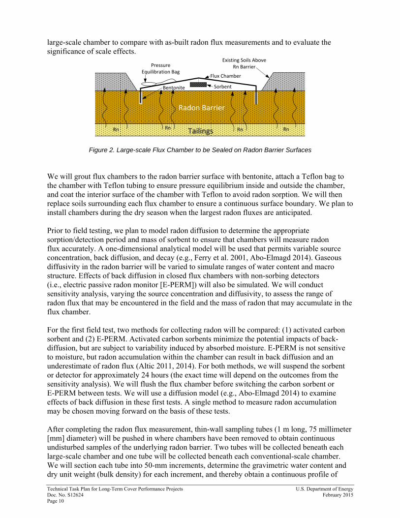
rates. For example, a dry site with a relatively thin cover profile, mature woody vegetation, a highly compacted clay radon barrier, and tailings with relatively high radium levels may be most vulnerable to an increase in radon flux. Existing data on site conditions will need to be compiled as a basis for scoring, ranking, and selecting the four study sites. 4.2.2 Soil Morphology Soil formation (pedogenesis) is inevitable and ubiquitous in all natural landscapes. Soi1 scientists recognize five major factors that influence soil formation: parent material, climate, living organisms, topography, and time. The combined influence of these soil-forming factors determines the biotic and abiotic properties of a soil and their degree of expression. The morphology of a soil is the collection of observable characteristics (properties) that reflect both in situ conditions and local soil-forming processes. Soil scientists use morphological characteristics such as structure (aggregation of particles and formation of cracks between aggregates), texture (proportions of sand, silt, and clay), and diagnostic horizons (properties of soil profile layers that provide evidence of specific pedogenic processes) to classify soils (Soil Survey Staff 1975, 2003). Given the significant physical alterations needed to accommodate engineering design goals, UMTRCA cover systems represent novel soil systems and are classified by soil scientists as Technosols (soils of human construction). In the effort to determine rates of soil change with implications for as-designed engineering conditions, we will characterize and classify the morphology of engineered cover profiles and natural analog soil profiles to understand (1) the processes that are changing soil engineering properties, and (2) the degree of change that occurs in both the near term (decades) and long term (millennia). Natural analogs are sites with undisturbed soil types similar the cover soils and late-successional vegetation (ideally an undisturbed area at the soil borrow site for the radon barrier). Soil morphology will be characterized in test pits excavated on disposal cell covers and at natural analog sites using standard soil survey methods, soil micromorphology, and digital soil morphometrics (electrical conductivity, x-ray fluorescence, and near-infrared mapping of soil profiles). Given the novel technogenic nature of UMTRCA cover systems, the systematic identification and morphological characterization of natural analog sites will allow the extensive body of literature on soil change in natural soil systems to be integrated with confidence. 4.2.3 Radon Flux Measurements Representative radon flux measurements will be needed at selected sites to compare with the regulatory radon flux standard (20 pCi m−2 s−1) and with as-built radon flux measurements. We plan to measure radon fluxes at 6-10 locations at each of the four sites using both large-scale and conventional-scale (Burnett et al. 1995) flux chambers. The large-scale chambers (1.5 meter (m) × 1.5 m square) are adapted from the inner “ring” of sealed-double ring infiltrometers (SDRIs) that we used previously to capture effects of pedogenic processes on soil hydraulic properties (Benson et al. 2006, 2008, 2011). The large scale is necessary to ensure that radon flux measurements are made over an area sufficiently large to encompass radon movement through macropore structure in the radon barrier. Large-scale chambers will be sealed to the surface of radon barriers after overlying riprap and bedding layer materials have been moved (Figure 2). We will place three conventional-scale flux chambers (0.3 m diameter) around each
Technical Task Plan for Long-Term Cover Performance Projects U.S. Department of Energy Doc. No. S12624 February 2015 Page 10
large-scale chamber to compare with as-built radon flux measurements and to evaluate the significance of scale effects.
Figure 2. Large-scale Flux Chamber to be Sealed on Radon Barrier Surfaces We will grout flux chambers to the radon barrier surface with bentonite, attach a Teflon bag to the chamber with Teflon tubing to ensure pressure equilibrium inside and outside the chamber, and coat the interior surface of the chamber with Teflon to avoid radon sorption. We will then replace soils surrounding each flux chamber to ensure a continuous surface boundary. We plan to install chambers during the dry season when the largest radon fluxes are anticipated. Prior to field testing, we plan to model radon diffusion to determine the appropriate sorption/detection period and mass of sorbent to ensure that chambers will measure radon flux accurately. A one-dimensional analytical model will be used that permits variable source concentration, back diffusion, and decay (e.g., Ferry et al. 2001, Abo-Elmagd 2014). Gaseous diffusivity in the radon barrier will be varied to simulate ranges of water content and macro structure. Effects of back diffusion in closed flux chambers with non-sorbing detectors (i.e., electric passive radon monitor [E-PERM]) will also be simulated. We will conduct sensitivity analysis, varying the source concentration and diffusivity, to assess the range of radon flux that may be encountered in the field and the mass of radon that may accumulate in the flux chamber. For the first field test, two methods for collecting radon will be compared: (1) activated carbon sorbent and (2) E-PERM. Activated carbon sorbents minimize the potential impacts of back-diffusion, but are subject to variability induced by absorbed moisture. E-PERM is not sensitive to moisture, but radon accumulation within the chamber can result in back diffusion and an underestimate of radon flux (Altic 2011, 2014). For both methods, we will suspend the sorbent or detector for approximately 24 hours (the exact time will depend on the outcomes from the sensitivity analysis). We will flush the flux chamber before switching the carbon sorbent or E-PERM between tests. We will use a diffusion model (e.g., Abo-Elmagd 2014) to examine effects of back diffusion in these first tests. A single method to measure radon accumulation may be chosen moving forward on the basis of these tests. After completing the radon flux measurement, thin-wall sampling tubes (1 m long, 75 millimeter [mm] diameter) will be pushed in where chambers have been removed to obtain continuous undisturbed samples of the underlying radon barrier. Two tubes will be collected beneath each large-scale chamber and one tube will be collected beneath each conventional-scale chamber. We will section each tube into 50-mm increments, determine the gravimetric water content and dry unit weight (bulk density) for each increment, and thereby obtain a continuous profile of
Flux Chamber
Bentonite
Pressure Equilibration Bag
Sorbent
Radon Barrier
Tailings
Existing Soils Above Rn Barrier
RnRn RnRn
U.S. Department of Energy Technical Task Plan for Long-Term Cover Performance Projects February 2015 Doc. No. S12624 Page 11
volumetric water content and water saturation. We will also measure total water potential in each increment using a chilled mirror hygrometer to define a continuous profile of pore water potential. For a second measure of radon, lead-210 sorbed on the radon barrier soil will be measured in the tubes by gamma emission and direct measurement by inductively coupled plasma mass spectrometry following acid extraction. Profiles of sorbed lead-210 can be used as an indicator of Rn flux, as lead-210 is a relatively long-lived (22-year half-life) decay product of radon. Profiles of water saturation will be used to compute diffusivity. 4.2.4 Depth-Dependent Soil Hydraulic Properties Profiles of soil physical and hydraulic properties will be needed to test hypotheses about depths of soil-forming processes and effects on percolation rates. After completing radon flux tests and removing chambers in a test pit, we plan to collect large-scale (450 mm diameter) undisturbed block samples of the radon barrier in a stacked arrangement (Benson et al. 2011, and ASTM D D7015-13). Once block sampling is complete, we will characterize soil morphology (Soil Survey Staff 1975), including macropore structure, on the sample pit face. Macropore structure will also be mapped using the methods described in Benson et al. (2006). Each block sample will be trimmed to a diameter of 305 mm in the laboratory for saturated hydraulic conductivity testing using the procedures described in Benson et al. (2011) and ASTM D 5084. Samples of this size are sufficiently large to capture the impacts of soil structural development due to pedogenesis (Benson et al. 2006, 2008, 2011). We will apply an effective stress during hydraulic conductivity testing to simulate the stress that would be encountered at the depth that the block sample was taken. After completing a hydraulic conductivity test, we will measure the soil water characteristic curve (SWCC) of each block sample using a pressure plate method (ASTM D6836). The same large-scale testing apparatus described in Benson et al. (2011) will be used for both the hydraulic conductivity and SWCC tests. This apparatus is sufficiently large to capture features that control liquid and gaseous fluxes in cover soils that have developed macropore structure. We will use the hydraulic conductivity and SWCC to construct profiles of radon barrier hydraulic properties. These profiles will be compared to either measured or expected hydraulic property profiles documented in engineering and as-built construction reports. We will estimate profiles of gaseous diffusivity on the basis of profiles for SWCCs, pore water potential, and the diffusivity equation in Elberling et al. (1993). These profiles will be compared to the gaseous diffusivity assumed during design of the UMTRCA facility. 4.2.5 Summary of Data Analysis Several data analysis tools will be used to test study questions and draw conclusions with respect to the project objectives (Section 4.1). Radon fluxes measured and modeled for current radon barrier profile conditions will be statistically compared to estimates as modeled using Regulatory Guide 3.64 (NRC 1989), and as measured at the time of construction, to determine if changes in engineering properties and performance have occurred during a radon barrier’s service life. Radon fluxes measured with the large-scale and conventional-scale (smaller-scale) flux chambers in the current study will be compared to each other to determine if a scale-effect exists, and to quantify the magnitude of the scale effect. We will incorporate any scale effects into the comparison of the fluxes measured in the current study and those measured immediately after
Technical Task Plan for Long-Term Cover Performance Projects U.S. Department of Energy Doc. No. S12624 February 2015 Page 12
construction. Comparison will also be adjusted for differences in soil water content existing immediately after construction and at the time of the current assessment, and for changes in source concentration that may have occurred due to radioactive decay in the underlying tailings since the cover was installed. Percolation rates will be estimated for each test profile using the program WinUNSAT-H (e.g., Bohnhoff et al. 2009), measured soil hydraulic properties, and site meteorological records. We will use Vadose/W for analysis of sites where snow and a frozen surface may be important. Both WinUNSAT-H and Vadose/W have been shown to provide reliable hydrological predictions when parameterized using realistic hydraulic properties that are representative of field conditions (Ogorzalek et al. 2008, Bohnhoff et al. 2010). We will also estimate percolation using measured or expected hydraulic properties at the time of construction, and then compare the two sets of estimates to assess how the percolation rate may have changed in response to pedogenesis. 4.3 Collaborators The design, funding, and implementation of this project are products of collaboration between the following researchers and federal agencies: William Albright, PhD Division of Hydrologic Sciences Desert Research Institute
William Likos, PhD Geological Engineering University of Wisconsin-Madison
Craig Benson, PhD Civil and Environmental Engineering University of Wisconsin-Madison
William Waugh, PhD Ecohydrology Group Stoller Newport News Nuclear, Inc. (SN3), a wholly owned subsidiary of Huntington Ingalls Industries, Inc.
Mark Fuhrman, PhD Office of Nuclear Regulatory Research U.S. Nuclear Regulatory Commission
Morgan Williams (PhD candidate) Department of Geography University of California-Berkeley
References (for entire Technical Task Plan)
Abo-Elmagd, Mahmoud, 2014. “Radon Exhalation Rates Corrected for Leakage and Back Diffusion – Evaluation of Radon Chambers and Road Sources with Application to Ceramic Tile,” Journal of Radiation Research and Applied Sciences, 1-9. Altic, N., 2014. Pilot Study Report for Radon Exhalation Measurements Oak Ridge, Tennessee, DCN 2052-TR-01-0, Oak Ridge Associated Universities, April. Benson, C., Albright, W., Wang, X., and MacDonald, E. 2006, “Assessment of the ACAP Test Sections at Kiefer Landfill: Hydraulic Properties and Geomorphology,” Geo Engineering Report No. 02-16, University of Wisconsin, Madison, Wisconsin. Benson, C., Lee, S., Wang, X., Albright, W., and Waugh, W., 2008. Hydraulic Properties and Geomorphology of the Earthen Component of the Final Cover at the Monticello Uranium Mill Tailings Repository, Geological Engineering Report No. 08-04, University of Wisconsin, Madison, Wisconsin. Benson, C., Sawangsuriya, A., Trzebiatowski, B., and Albright, W., 2007. “Post-Construction Changes in the Hydraulic Properties of Water Balance Cover Soils,” Journal of Geotechnical and Geoenvironmental Engineering, 133(4): 349–359. Bohnhoff, G., Ogorzalek, A., Benson, C., Shackelford, C., and Apiwantragoon, P., 2009. “Field Data and Water-Balance Predictions for a Monolithic Cover in a Semiarid Climate,” Journal of Geotechnical and Geoenvironmental Engineering, 135(3): 333–348. Burnett, W. Cable, P., and Chanton, J., 1995. “A Simple Passive Collector for Direct Measurement of Radon Flux from Soil,” Journal of Radiological and Nuclear Chemistry, 192(2): 281–290. Elberling, B., R. Nicholson, and D. David, 1993. “Field Evaluation of Sulphide Oxidation Rates, Nordic Hydrology,” 24(5): 323–338. Ferry, C., Richon, P., Beneito, A., and Robe, M., 2001. “Radon Exhalation from Uranium Mill Tailings: Experimental Validation of a 1-D Model,” Journal of Environmental Radioactivity, 54(1): 99–108. NRC (U.S. Nuclear Regulatory Commission), 1989. Calculation of Radon Flux Attenuation by Earthen Uranium Mill Tailings Covers, Regulatory Guide 3.64. Ogorzalek, A., G. Bohnhoff, C. Shackelford, C. Benson, and P. Apiwantragoon, 2008. “Comparison of Field Data and Water-Balance Predictions for a Capillary Barrier Cover.” Journal of Geotechnical and Geoenvironmental Engineering, 134(4): 470–486. Soil Survey Staff, 1975. “Soil taxonomy: a basic system of soil classification for making and interpreting soil surveys,” second edition, National Resources Conservation Service, U.S. Department of Agriculture Handbook 436. Soil Survey Staff, 2014. “Keys to soil taxonomy,” twelfth edition, USDA-Natural Resources Conservation Service, Washington, DC.

This page intentionally left blank
Appendix B
Bluewater Cover Design and Construction Review

This page intentionally left blank
Geo-Smith Engineering, LLC
Bluewater Cover Design and Construction Review
This report is a review of historical cover design and construction documents for the Bluewater, New Mexico disposal cell. The purpose of the review is to acquire information on cover design objectives, specifications, and as-built conditions. This information is needed as a baseline for an evaluation of the current performance of the disposal cell cover, and to project the long-term performance of the cover.
Two historical documents were reviewed for this report: the Bluewater Mill Reclamation Plan (ARCO Coal Company, March 1990. “Reclamation Plan, Bluewater Mill, Volumes 1, 2, and 3”) and As-Built Completion Report (Atlantic Richfield Company, March 1996. “Completion Report for Reclamation of the Bluewater Mill Site”, Volumes 1-4). Overall cell performance and issues concerning ground water compliance are not performed in this review. Only design and as-built information for the cover system (erosion protection, control of radon emanations and infiltration) is included herein.
This report reviews the following items concerning the disposal cell in order to evaluate the current performance of the cover. Each item is discussed in subsequent sections with a similar number.
1. Design criteria for soil physical and hydraulic properties for the low-permeability radon barrier and underlying relocated contaminated materials.
2. As-built data for the soil type, placement and compaction of the low-permeability radon barrier.
3. Soil edaphic properties for the radon barrier.4. Design disposal cell geometry including slope grades for the cover and as-built data
on slopes and any depressions.5. Slope stability calculations. 6. Soil water balance or percolation flux calculations and/or modeling.7. Radon flux modeling input data and results.8. Calculations or modeling of runoff and lateral drainage.9. Evaluations of potential uptake of contaminants of concern by deep-rooted plants.
10. Other concerns.
Section 1, Design criteria for soil physical and hydraulic properties for the low-permeability radon barrier and underlying relocated contaminated materials.
Criteria for design of disposal of uranium mill tailings is stated in the regulation “HEALTH AND ENVIRONMENTAL PROTECTION STANDARDS FOR URANIUM AND THORIUM MILL TAILINGS, 40 CFR 192”, As stated; control of residual radioactive materials and their listed constituents shall be designed to:
1
Geo-Smith Engineering, LLC
(a) Be effective for up to one thousand years, to the extent reasonably achievable, and, in any case, for at least 200 years, and, (b) Provide reasonable assurance that releases of radon-222 from residual radioactive material to the atmosphere will not:
1) Exceed an average 2 release rate of 20 picocuries per square meter per second or, 2) Increase the annual average concentration of radon-222 in air at or above any location outside the disposal site by more than one-half picocurie per liter.
(c) Provide reasonable assurance of conformance with groundwater protection provisions.
Thus the general goal or design criteria is permanent isolation of tailings and associated contaminants by minimizing dispersion by natural forces, and to do so without ongoing maintenance.
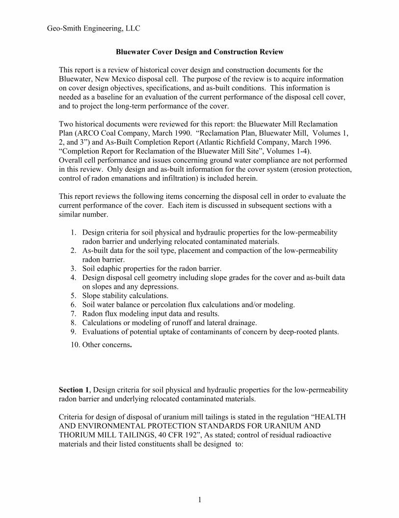
Information provided in Table 1 below indicates the type of soil material designed for the radon barrier. Material consists of low-plasticity clay and sandy clay. Laboratory testing of radon barrier permeability were performed in accordance with US Army Corps of Engineers, EM-1110-2-1906, Falling-Head Permeability Test with Permeameter Cylinder on 10 composite radon barrier samples..
Table 1, Water Permeabilities for the Composite Radon Barrier Samplesa,
Composite Sample Soil Classificationb Water Permeability (cm/s)USCS USDA
1 CL Clay Loam 1.9 x 10⁻⁸
2 CL Clay Loam 1.7 x 10⁻⁸
3 CL Clay 1.2 x 10⁻⁸
4 CL Sandy Clay Loam 3.3 x 10⁻⁷
5 SC Sandy Clay Loam 1.1 x 10⁻⁷
6 CL Clay 2.2 x 10⁻⁸
7 SC Sandy Clay Loam 9.0 x 10⁻⁸
8 SC Sandy Clay Loam 1.8 x 10⁻⁷
9 SC Sandy Loam 1.4 x 10⁻⁶
10 CL Clay Loam 1.5 x 10⁻⁸
a Reproduced from information provided on Table 7 found in the Reclamation Plan, Bluewater Mill Vol. 3, March 1990.
b Both soil classifications (USCS and USDA) were assigned by reviewing particle-size distribution data, Table 5; Specific Gravity and Atterberg Limit data, Table 8 found in the Reclamation Plan, Bluewater Mill Vol. 3, March 1990.
2
Geo-Smith Engineering, LLC
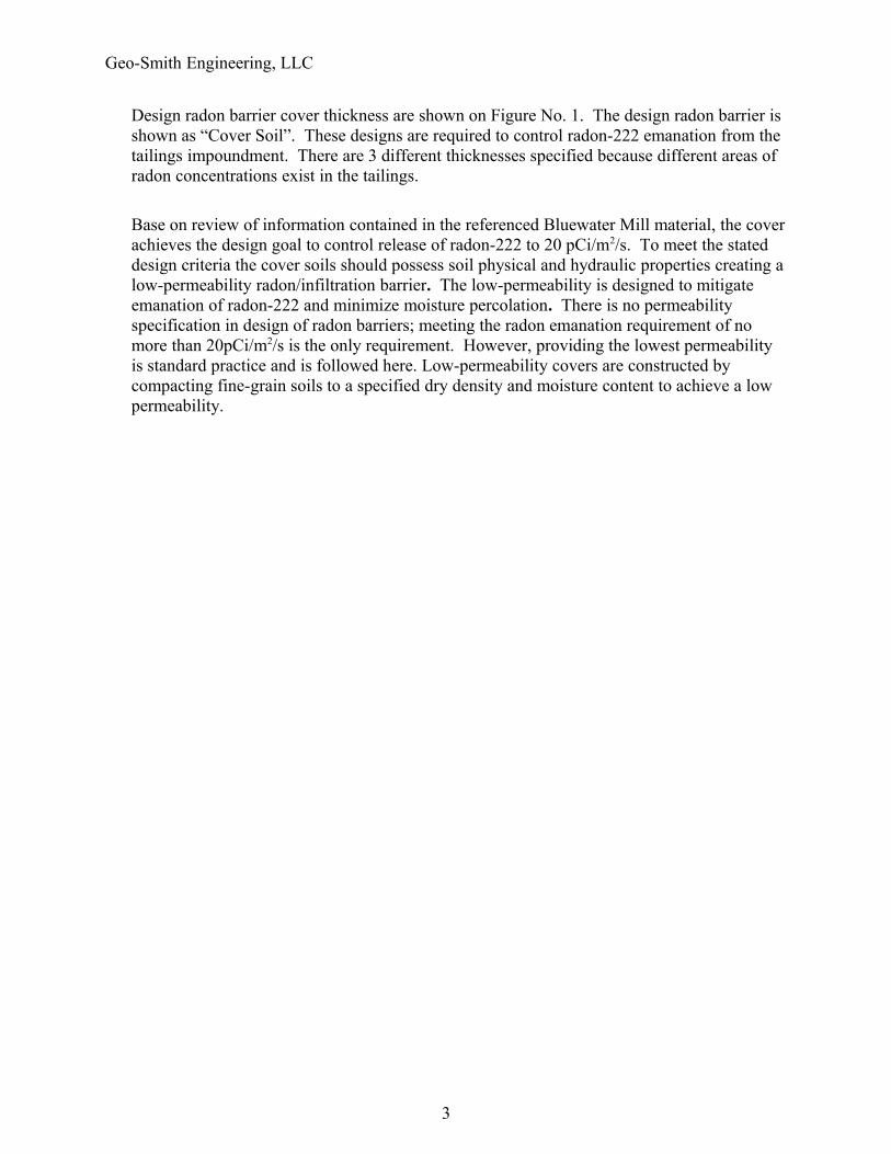
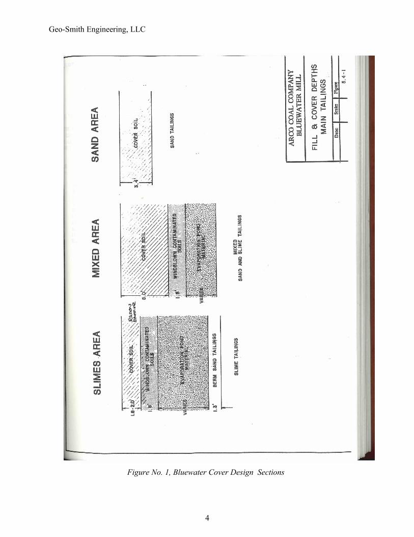
Design radon barrier cover thickness are shown on Figure No. 1. The design radon barrier is shown as “Cover Soil”. These designs are required to control radon-222 emanation from the tailings impoundment. There are 3 different thicknesses specified because different areas of radon concentrations exist in the tailings.
Base on review of information contained in the referenced Bluewater Mill material, the cover achieves the design goal to control release of radon-222 to 20 pCi/m2/s. To meet the stated design criteria the cover soils should possess soil physical and hydraulic properties creating a low-permeability radon/infiltration barrier. The low-permeability is designed to mitigate emanation of radon-222 and minimize moisture percolation. There is no permeability specification in design of radon barriers; meeting the radon emanation requirement of no more than 20pCi/m2/s is the only requirement. However, providing the lowest permeability is standard practice and is followed here. Low-permeability covers are constructed by compacting fine-grain soils to a specified dry density and moisture content to achieve a low permeability.
3
Geo-Smith Engineering, LLC
Figure No. 1, Bluewater Cover Design Sections
4
Geo-Smith Engineering, LLC
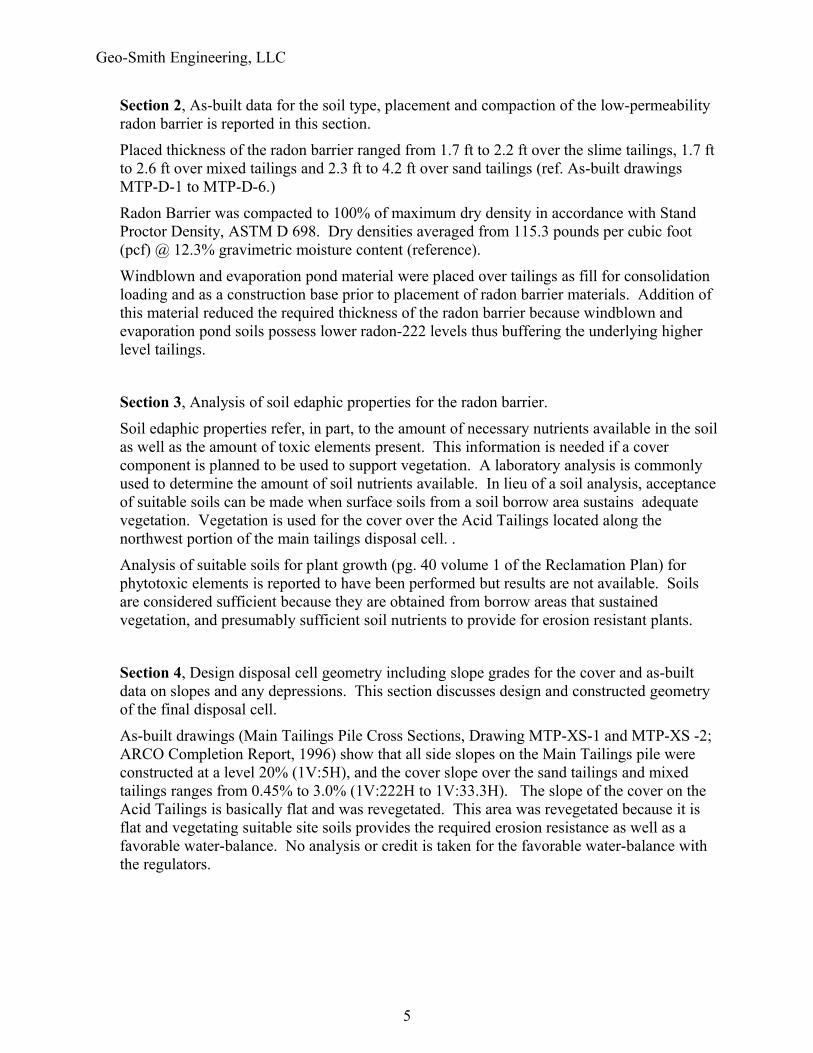
Section 2, As-built data for the soil type, placement and compaction of the low-permeability radon barrier is reported in this section.
Placed thickness of the radon barrier ranged from 1.7 ft to 2.2 ft over the slime tailings, 1.7 ft to 2.6 ft over mixed tailings and 2.3 ft to 4.2 ft over sand tailings (ref. As-built drawings MTP-D-1 to MTP-D-6.)
Radon Barrier was compacted to 100% of maximum dry density in accordance with Stand Proctor Density, ASTM D 698. Dry densities averaged from 115.3 pounds per cubic foot (pcf) @ 12.3% gravimetric moisture content (reference).
Windblown and evaporation pond material were placed over tailings as fill for consolidation loading and as a construction base prior to placement of radon barrier materials. Addition of this material reduced the required thickness of the radon barrier because windblown and evaporation pond soils possess lower radon-222 levels thus buffering the underlying higher level tailings.
Section 3, Analysis of soil edaphic properties for the radon barrier.
Soil edaphic properties refer, in part, to the amount of necessary nutrients available in the soil as well as the amount of toxic elements present. This information is needed if a cover component is planned to be used to support vegetation. A laboratory analysis is commonly used to determine the amount of soil nutrients available. In lieu of a soil analysis, acceptance of suitable soils can be made when surface soils from a soil borrow area sustains adequate vegetation. Vegetation is used for the cover over the Acid Tailings located along the northwest portion of the main tailings disposal cell. .
Analysis of suitable soils for plant growth (pg. 40 volume 1 of the Reclamation Plan) for phytotoxic elements is reported to have been performed but results are not available. Soils are considered sufficient because they are obtained from borrow areas that sustained vegetation, and presumably sufficient soil nutrients to provide for erosion resistant plants.
Section 4, Design disposal cell geometry including slope grades for the cover and as-built data on slopes and any depressions. This section discusses design and constructed geometry of the final disposal cell.
As-built drawings (Main Tailings Pile Cross Sections, Drawing MTP-XS-1 and MTP-XS -2; ARCO Completion Report, 1996) show that all side slopes on the Main Tailings pile were constructed at a level 20% (1V:5H), and the cover slope over the sand tailings and mixed tailings ranges from 0.45% to 3.0% (1V:222H to 1V:33.3H). The slope of the cover on the Acid Tailings is basically flat and was revegetated. This area was revegetated because it is flat and vegetating suitable site soils provides the required erosion resistance as well as a favorable water-balance. No analysis or credit is taken for the favorable water-balance with the regulators.
5
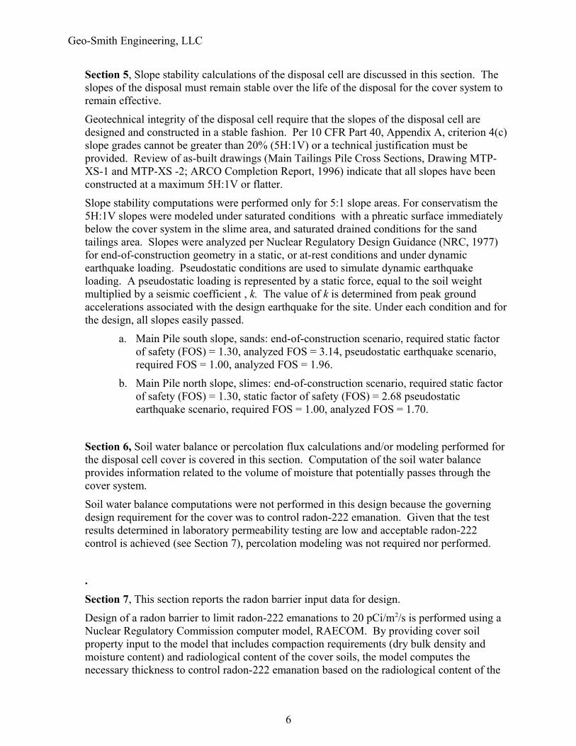
Geo-Smith Engineering, LLC
Section 5, Slope stability calculations of the disposal cell are discussed in this section. The slopes of the disposal must remain stable over the life of the disposal for the cover system to remain effective.
Geotechnical integrity of the disposal cell require that the slopes of the disposal cell are designed and constructed in a stable fashion. Per 10 CFR Part 40, Appendix A, criterion 4(c) slope grades cannot be greater than 20% (5H:1V) or a technical justification must be provided. Review of as-built drawings (Main Tailings Pile Cross Sections, Drawing MTP-XS-1 and MTP-XS -2; ARCO Completion Report, 1996) indicate that all slopes have been constructed at a maximum 5H:1V or flatter.
Slope stability computations were performed only for 5:1 slope areas. For conservatism the 5H:1V slopes were modeled under saturated conditions with a phreatic surface immediately below the cover system in the slime area, and saturated drained conditions for the sand tailings area. Slopes were analyzed per Nuclear Regulatory Design Guidance (NRC, 1977) for end-of-construction geometry in a static, or at-rest conditions and under dynamic earthquake loading. Pseudostatic conditions are used to simulate dynamic earthquake loading. A pseudostatic loading is represented by a static force, equal to the soil weight multiplied by a seismic coefficient , k. The value of k is determined from peak ground accelerations associated with the design earthquake for the site. Under each condition and for the design, all slopes easily passed.
a. Main Pile south slope, sands: end-of-construction scenario, required static factor of safety (FOS) = 1.30, analyzed FOS = 3.14, pseudostatic earthquake scenario, required FOS = 1.00, analyzed FOS = 1.96.
b. Main Pile north slope, slimes: end-of-construction scenario, required static factor of safety (FOS) = 1.30, static factor of safety (FOS) = 2.68 pseudostatic earthquake scenario, required FOS = 1.00, analyzed FOS = 1.70.
Section 6, Soil water balance or percolation flux calculations and/or modeling performed for the disposal cell cover is covered in this section. Computation of the soil water balance provides information related to the volume of moisture that potentially passes through the cover system.
Soil water balance computations were not performed in this design because the governing design requirement for the cover was to control radon-222 emanation. Given that the test results determined in laboratory permeability testing are low and acceptable radon-222 control is achieved (see Section 7), percolation modeling was not required nor performed.
.Section 7, This section reports the radon barrier input data for design.
Design of a radon barrier to limit radon-222 emanations to 20 pCi/m2/s is performed using a Nuclear Regulatory Commission computer model, RAECOM. By providing cover soil property input to the model that includes compaction requirements (dry bulk density and moisture content) and radiological content of the cover soils, the model computes the necessary thickness to control radon-222 emanation based on the radiological content of the
6
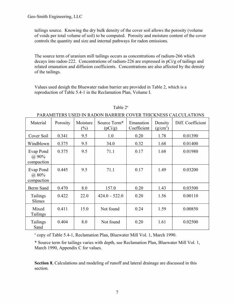
Geo-Smith Engineering, LLC
tailings source. Knowing the dry bulk density of the cover soil allows the porosity (volume of voids per total volume of soil) to be computed. Porosity and moisture content of the cover controls the quantity and size and internal pathways for radon emissions.
The source term of uranium mill tailings occurs as concentrations of radium-266 which decays into radon-222. Concentrations of radium-226 are expressed in pCi/g of tailings and related emanation and diffusion coefficients. Concentrations are also affected by the density of the tailings.
Values used desigh the Bluewater radon barrier are provided in Table 2, which is a reproduction of Table 5.4-1 in the Reclamation Plan, Volume I.
Table 2a
PARAMETERS USED IN RADON BARRIER COVER THICKNESS CALCULATIONS
Material Porosity Moisture (%)
Source Term* (pCi/g)
Emanation Coefficient
Density (g/cm3)
Diff. Coefficient
Cover Soil 0.341 9.5 1.0 0.20 1.78 0.01390
Windblown 0.375 9.5 34.0 0.32 1.68 0.01400
Evap Pond @ 90%
compaction
0.375 9.5 71.1 0.17 1.68 0.01980
Evap Pond @ 80%
compaction
0.445 9.5 71.1 0.17 1.49 0.03200
Berm Sand 0.470 8.0 157.0 0.20 1.43 0.03500
Tailings Slimes
0.422 22.0 424.0 – 522.0 0.20 1.56 0.00110
Mixed Tailings
0.411 15.0 Not found 0.24 1.59 0.00850
Tailings Sand
0.404 8.0 Not found 0.20 1.61 0.02500
a copy of Table 5.4-1, Reclamation Plan, Bluewater Mill Vol. 1, March 1990.
* Source term for tailings varies with depth, see Reclamation Plan, Bluewater Mill Vol. 1, March 1990, Appendix C for values.
Section 8, Calculations and modeling of runoff and lateral drainage are discussed in this section.
7
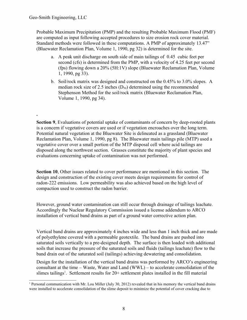
Geo-Smith Engineering, LLC
Probable Maximum Precipitation (PMP) and the resulting Probable Maximum Flood (PMF) are computed as input following accepted procedures to size erosion rock cover material. Standard methods were followed in these computations. A PMP of approximately 13.47” (Bluewater Reclamation Plan, Volume 1, 1990, pg 32) is determined for the site.
a. A peak unit discharge on south side of main tailings of 0.45 cubic feet per second (cfs) is determined from the PMP, with a velocity of 4.25 feet per second (fps) flowing down a 20% (5H:1V) slope (Bluewater Reclamation Plan, Volume 1, 1990, pg 33).
b. Soil/rock matrix was designed and constructed on the 0.45% to 3.0% slopes. A median rock size of 2.5 inches (D50) determined using the recommended Stephenson Method for the soil/rock matrix (Bluewater Reclamation Plan, Volume 1, 1990, pg 34).
.Section 9, Evaluations of potential uptake of contaminants of concern by deep-rooted plants is a concern if vegetative covers are used or if vegetation encroaches over the long term. Potential natural vegetation at the Bluewater Site is delineated as a grassland (Bluewater Reclamation Plan, Volume 1, 1990, pg 8). The Bluewater main tailings pile (MTP) used a vegetative cover over a small portion of the MTP disposal cell where acid tailings are disposed along the northwest section. Grasses constitute the majority of plant species and evaluations concerning uptake of contamination was not performed.
Section 10, Other issues related to cover performance are mentioned in this section. The design and construction of the existing cover meets design requirements for control of radon-222 emissions. Low permeability was also achieved based on the high level of compaction used to construct the radon barrier.
However, ground water contamination can still occur through drainage of tailings leachate. Accordingly the Nuclear Regulatory Commission issued a license addendum to ARCO installation of vertical band drains as part of a ground water corrective action plan.
Vertical band drains are approximately 4 inches wide and less than 1 inch thick and are made of polyethylene covered with a permeable geotextile. The band drains are pushed into saturated soils vertically to a pre-designed depth. The surface is then loaded with additional soils that increase the pressure of the saturated soils and fluids (tailings leachate) flow to the band drain out of the saturated soil (tailings) achieving dewatering and consolidation.
Design for the installation of the vertical band drains was performed by ARCO’s engineering consultant at the time – Waste, Water and Land (WWL) – to accelerate consolidation of the slimes tailings1. Settlement results for 20+ settlement plates installed in the fill material
1 Personal communication with Mr. Lou Miller (July 30, 2012) revealed that in his memory the vertical band drains were installed to accelerate consolidation of the slime deposit to minimize the potential of cover cracking due to
8
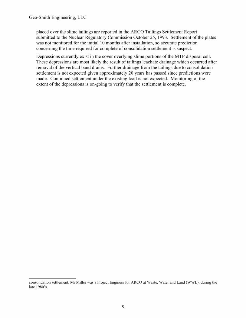
Geo-Smith Engineering, LLC
placed over the slime tailings are reported in the ARCO Tailings Settlement Report submitted to the Nuclear Regulatory Commission October 25, 1993. Settlement of the plates was not monitored for the initial 10 months after installation, so accurate prediction concerning the time required for complete of consolidation settlement is suspect.
Depressions currently exist in the cover overlying slime portions of the MTP disposal cell. These depressions are most likely the result of tailings leachate drainage which occurred after removal of the vertical band drains. Further drainage from the tailings due to consolidation settlement is not expected given approximately 20 years has passed since predictions were made. Continued settlement under the existing load is not expected. Monitoring of the extent of the depressions is on-going to verify that the settlement is complete.
consolidation settlement. Mr Miller was a Project Engineer for ARCO at Waste, Water and Land (WWL), during the late 1980’s.
9
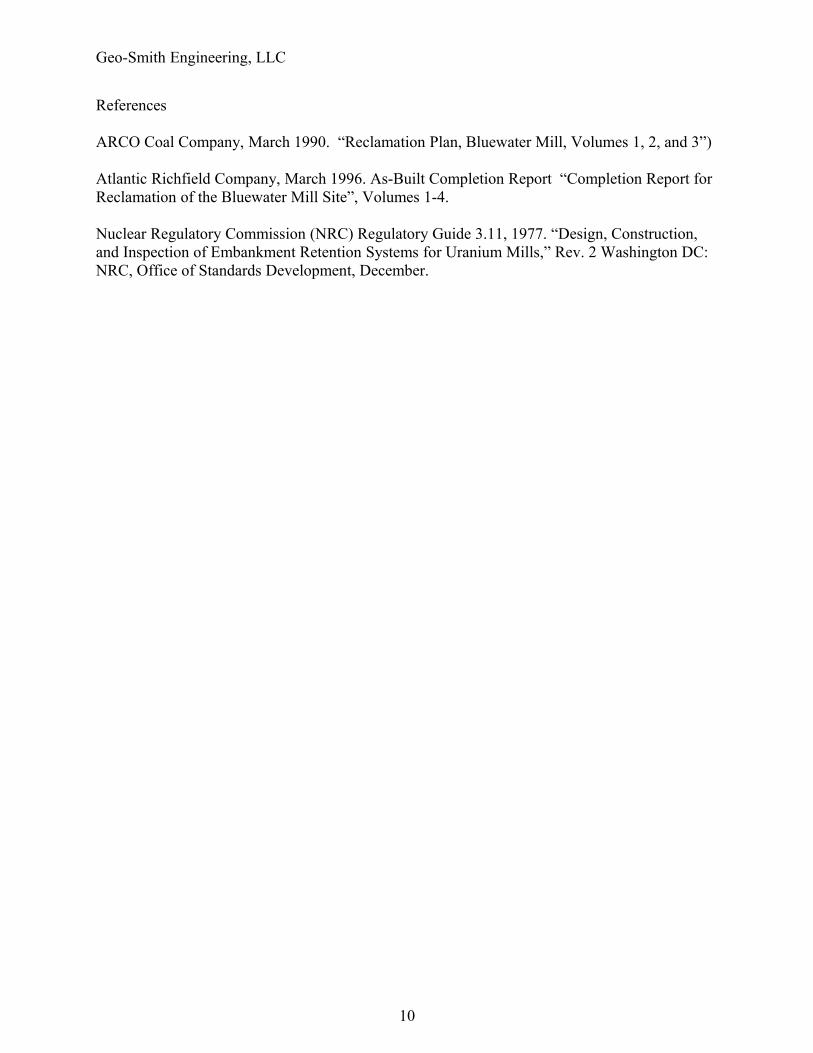
Geo-Smith Engineering, LLC
References
ARCO Coal Company, March 1990. “Reclamation Plan, Bluewater Mill, Volumes 1, 2, and 3”)
Atlantic Richfield Company, March 1996. As-Built Completion Report “Completion Report for Reclamation of the Bluewater Mill Site”, Volumes 1-4.
Nuclear Regulatory Commission (NRC) Regulatory Guide 3.11, 1977. “Design, Construction, and Inspection of Embankment Retention Systems for Uranium Mills,” Rev. 2 Washington DC: NRC, Office of Standards Development, December.
10