Embed Size (px)
Citation preview
66 TRANSPORTATION RESEARCH RECORD 1227
Effects of Transverse Distribution of Heavy Vehicles on Thickness Design of Full-Depth Asphalt Pavements
R. BUITER, W. M. H. CORTENRAAD, A. c. VAN ECK AND H. VAN RIJ
One of the most important parameters involved in the design of 1·oad pavements is the expected traffic load. This factor has a direct hearing on the thickness requirements of the 11avcment. For pract"ical purposes, only the loading from heavy-goods vehicles should be considered a , in comparison, the loading from 11rivatc cars has a negligible effect. When deciding on the la er thickncs es of a road pavement, it is essential lo know whether the traffic will be concentrated in one wheel path, or distributed across the width of the traffic lane. When commercial chicles travelling along a roadway use wheel paths that are transversely distributed across the trnffic lane (lateral shifts or the wheel path), the pavement is less severely loaded at representative points in the cross section than when the vehicles all follow the same wheel path (uniform wheel path). The Road and Hydraulic Engineering Division of the Dutch Department of Public Works has carried out further research into the phenomenon of transversely distributed heavy-goods vehicles and the effect of latcnil shifts of the wheel path on the design of flexible panments. The study was particularly concerned with investigating how this phenomenon relates lo roads with a fulldepth asphalt pavement with specific material properties.
The first part of the research project involved studying the influence of the width of the traffic lane on the wheel-path distribution. Relevant field data were obtained from tests conducted with a specially developed measuring system. It was shown that the lateral wheel-shift pattern of heavy-goods vehicles could be accurately represented by a normal distribution. The standard deviation (also called the lateral spread) associated with the normal distribution was taken to determine the extent to which wheel paths were spread out across the traffic lane. By dividing the traffic lanes into three width classes, characteristic lateral spreads were determined, which could be used as a basis for designing suitable asphalt layer thicknesses.
During the second phase of the research pr ject, a design factor (the wheel-path shift fa<.:tor) was de fined to account for lateral shifts of the wheel path. This enabled the thickness of the asphalt layer to be linked to the lateral spread (or standard devialion) of the nc>rmal distnbution. Furthermore by applying the' heel-path shift factor (or simply ca lled the shift factor) to various traffic loads, a relationship was established between the thickness requirements of the asphalt and the lateral spread of the normal distribution. The maximum horizontal (tangential) strain occurring at the bottom of the asphalt
Road and Hydraulic Engineering Division, Ministry of Transport and Public Works, P.O. Box 5044, 2600 GA Delft, Netherlands.
layer was assumed to be representative of the likely fatigue effects in the structure.
The third phase of the research work involved comparing the new approach for dealing with lateral shifts in the wheel paths with the method that had been used in the Netherlands until recently. It was concluded that the previous basis for estimating the effects of lateral wheel-path shift phenomena was incorrect. As a result, the new approach outlined in this paper has now been incorporated into the Pavement Design Manual used by the Road and Hydraulic Engineering Division, Department of Public Works , in the Netherlands.
EFFECT OF LANE WIDTH ON LATERAL SPREAD
Lane Width
Several factors influence whether a driver follows a fixed wheel path. Some such factors include the following:
• Wea ther conditions (such as wind and precipitation), • Time (hour, day month) , • Heavy-goods vehicle used (type, load, and width), • Traffic conditions -peed, intensity, prop rtion of heavy
goods v hicles, oncoming traffic, traffic restrictions, and visibility),
• Road characteristics (type of road, road surface, number of lanes, road roughness, traffic-lane width, width of the hard shoulder, superelevation, alignment, and road markings), and
• Enviro 1J ment (open Hrea , w od lands , built-up area, flyovers , tun nels , traffic barriers, and obstacles).
In the literature (1-7) dealing with the subject of transverse distributions of traffic loads caused by heavy-goods vehicles, it is generally concluded that the width of the traffic lane is the most significant parameter in determining the extent to which the wheel paths are distributed over the road surface.
The other factors mentioned above are primarily concerned with the most heavily loaded point in the pavement structure. The shape of the transverse distribution and, therefore, the extent to which damage is caused to the pavement structure below the most heavily loaded point are less affected by such factors. As a consequence, the current investigations have been restricted to examining the role played by the trafficlane width in lateral whed-palh shift phenomena .
Buiter et al. 67
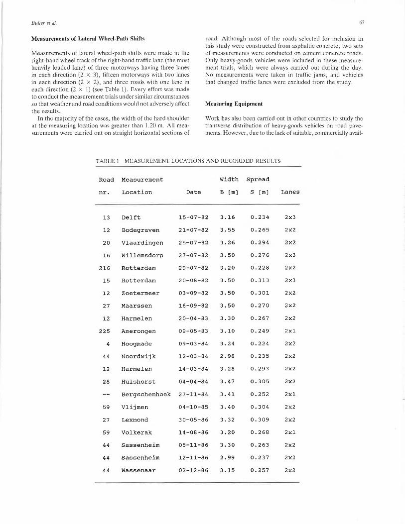
Measurements of Lateral Wheel-Path Shifts
Measurements of lateral wheel-path shifts were made in the right-hand wheel track of the right-hand traffic lane (the most heavily loaded lane) of three motorways having three lanes in each direction (2 x 3), fifteen motorways with two lanes in each direction (2 x 2), and three roads with one lane in each direction (2 x 1) (see Table 1). Every effort was made to conduct the measurement trials under similar circumstances so that weather and road conditions would not adversely affect the results.
road. Although most of the roads selected for inclusion in this study were constructed from asphaltic concrete , two sets of measurements were conducted on cement concrete roads. Only heavy-goods vehicles were included in these measurement trials, which were always carried out during the day. No measurements were taken in traffic jams, and vehicles that changed traffic lanes were excluded from the study.
Measuring Equipment
In the majority of the cases, the width of the hard shoulder at the measuring location was greater than 1.20 m. All measurements were carried out on straight horizontal sections of
Work has also been carried out in other countries to study the transverse distribution of heavy-goods vehicles on road pavements. However, due to the lack of suitable , commercially avail-
TABLE 1 MEASUREMENT LOCATIONS AND RECORDED RESULTS
Road Measurement Width Spread
nr. Location Date B [m] s [m] Lanes
13 Delft 15-07-82 3.16 0.234 2x3
12 Bodegraven 21-07-82 3.55 0.265 2X2
20 Vlaardingen 25-07-82 3.26 0.294 2x2
16 Willemsdorp 27-07-82 3.50 0 . 276 2x3
216 Rotterdam 29-07-82 3.20 0.228 2x2
15 Rotterdam 20-08-82 3.50 0.313 2x3
12 Zoetermeer 03-09-82 3.50 0.301 2x2
27 Maarssen 16-09-82 3.50 0.270 2x2
12 Harmelen 20-04-83 3.30 0.267 2X2
225 Amerongen 09-05-83 3.10 0.249 2xl
4 Hoogmade 09-03-84 3.24 0.224 2x2
44 Noordwijk 12-03-84 2.98 0.235 2X2
12 Harmelen 14-03-84 3.28 0.293 2x2
28 Hulshorst 04-04-84 3.47 0.305 2x2
Bergschenhoek 27-11-84 3.41 0.252 2xl
59 Vlijmen 04-10-85 3.40 0.304 2x2
27 Lexmond 30-05-86 3. 32 o. 309 2X2
59 Volkerak 14-08-86 3.20 0.268 2xl
44 Sassenheim 05-11-86 3.30 0.263 2x2
44 Sassenheim 12-11-86 2.99 0.237 2x2
44 Wassenaar 02-12-86 3.15 0.257 2x2
68
able equipment, most of the research institutes involved have been obliged to develop their own measuring devices for registering the transverse position of wheels ( 8-10).
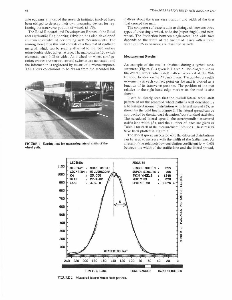
The Road Research and Development Branch of the Road and Hydraulic Engineering Division has also developed equipment capable of performing such measurements. The sensing element in this unit consists of a thin mat of synthetic material, which can be readily attached to the road surface using double-sided adhesive tape. The mat contains 120 switch elements, each 0.02 m wide. As a wheel or wheel configuration crosses the sensor, several switches are activated, and the information is registered by means of a microcomputer. This allows conclusions to be drawn from the recorded bit-
FIGURE I Sensing mat for measuring lateral shifts of the wheel path.
1100
1000
900
BOO
700
600
500
400
300
200
100
LEG ENDA
HIGHWAY I R016 <WEST> LOCATION 1 WILLEMSDORP KM I 25, 000 DATE I 27-7-B2 LANE I 3, 50 M
TRANSPORTATION RESEARCH RECORD 1227
pattern about the transverse position and width of the tires that crossed the mat.
The computer software is able to distinguish between three types of tires: single-wheel, wide tire (super single), and twinwheel. The distinction between single-wheel and wide tires depends on the width of the tire tread. Tires with a tread width of 0.25 m or more are classified as wide.
Measurement Results
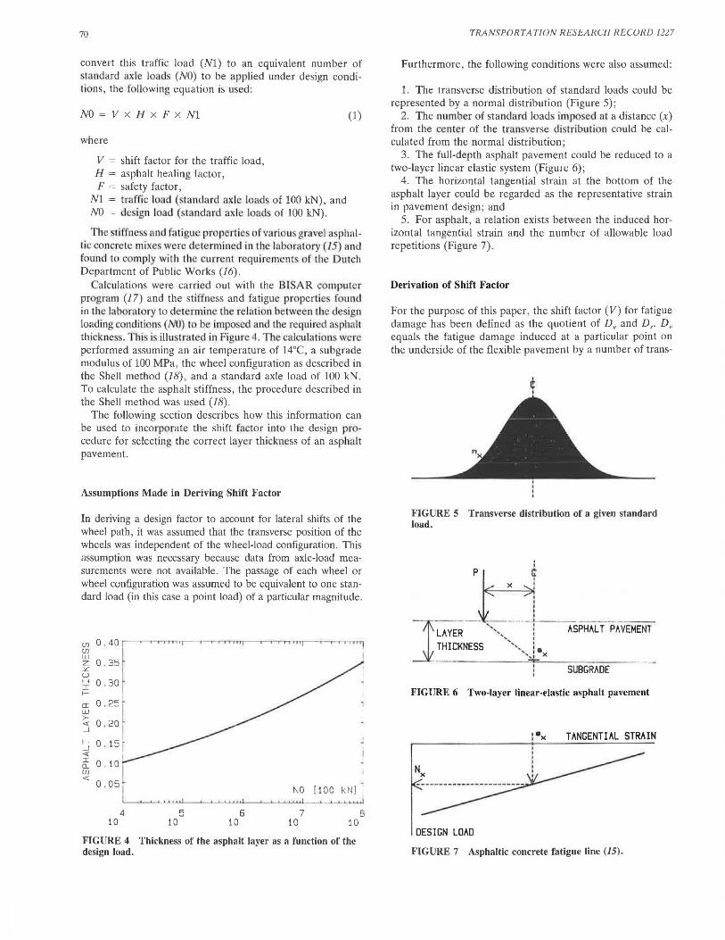
An example of the results obtained during a typical measurement (Figure 1) is given in Figure 2. This diagram shows the overall lateral wheel-shift pattern recorded at the Willemsdorp location on the A16 motorway. The number of switch movements at each contact point on the mat is plotted as a function of its transverse position. The position of the mat relative to the right-hand edge marker on the road is also shown.
It can be clearly seen that the overall lateral wheel-shift pattern of all the recorded wheel paths i well described by a b II-shaped normal distribution with lateral pread (S) , as h wn by the bold line in Figure 2. The lateral prcad can be
approached by the standard deviation from standard statistics. The calculated lateral spread, the corresponding measured traffic lane width (B) , and the number of lanes are given in Table 1 for each of the measurement locations. These results have been plotted in Figure 3.
The lateral spread associated with the different distributions can be seen to increase with the width of the traffic lane. As a result of th· relatively low rr lation coefficient (r = 0.63) between the width of the traffic lane and the lat ral spread,
RESULTS
B55 165
134B 656
SINGLE WHEELS 1
SUPER SINGLES 1
TWIN WHEELS VEHICLES SPREAD CS) • a. 276 M
240 220 200 lBO 160 140 120 100 BO 60 40 20 0
TRAFFIC LANE EDGE MARKER HARD SHOULDER
FIGURE 2 Mc11surcd lateral wheel-shift pattern.

Bui/er et al.
it was decided that a linear regression analysis would be inappropriate. As a practial solution, the fairly narrow range of traffic lane widths was subdivided into three classes, 0.25 m apart (Figure 3). The average lateral spread of the normal distributions for each width classification has been determined and is shown in Table 2.
Analysis of the results revealed no grounds for deriving different average lateral spreads for each type of road. Moreover, the measurements showed that the center of the normal distribution-which is considered to be the most heavily loaded point-is not at a constant distance from the right-hand edge marker on the road. An explanation of this phenomenon is outside the scope of the present paper. Finally, it should be noted that research has shown (11,12) that the observed lateral spread cannot be simply linearly extrapolated to traffic lane widths outside the measured range.
RELATIONSHIP BETWEEN SPREAD AND ASPHALT THICKNESS
Design of Full-Depth Asphalt Pavements
In discussing the relationship between the lateral spread and the thickness requirements of an asphalt course for given
~ 0 .45
0 . 40 i~ ' 2 :;.IEE 3 ::;. i D >k <{ I I I
w 0 . 35 I I
a:
I I
I I Q. . I· . I (fJ 0 . 30 ..
I
1 _J ' I <{ ' ·
. I a: 0.25 • j I w .. I , I I- I I <( 0.20 I I
] _J I I I I
0. 15 I I
0 . 10 TRAFFIC-LANE WIDTH [M] j L.__.__
2.75 3.00 3.25 3.50 3.75
FIGURE 3 Calculated lateral spread plotted as a function of the measured lane width.
69
traffic loading conditions, attention is specifically focused in this paper on full-depth asphalt pavements. The required thickness of the asphalt layer is dependent on traffic load, climate , and the material properties of both the asphalt and the base course (subbase and subgrade) .
It is generally recognized that material properties are extremely difficult to measure accurately in the field. As a result, such properties are usually determined in the laboratory using standard tests. For instance, in the case of asphaltbased materials , dynamic flexural tests are typically used to measure stiffness and fatigue characteristics. The conditions under which bending tests of this type are carried out are strictly limited, with restrictions being placed on the size of the specimens and the test temperatures. Although these tests are conducted at several stress or strain levels , only one frequency is used (13). It is clear that the test conditions in the laboratory are not directly comparable to the actual situation in the field. In general, no consideration is given to the random loading spectrum , the random rest periods, or the seasonal influences that occur in practice .
To be able to translate the traffic loading distribution in practice into a design load, certain correction factors must be applied. The Road and Hydraulic Engineering Division uses an asphalt healing factor, to deal with the effects of intermittent loading and self-healing of asphalt material. Road damage in practice increases gradually . Based on a desired percentage of damage after the design life , a certain discrepancy between the design load and the traffic load should be created by multiplying the traffic load by a safety factor. In the future, a probabilistic approach of road design should give a prediction of damage based on variation in design parameters. A detailed treatment of the healing factor and the safety factor and how they should be applied is outside the scope of this paper (14).
Lateral shifts of the wheel path cause the traffic load to be distributed across the transverse section . This means that, for a given traffic load, the asphalt course need not be as thick as when the traffic is concentrated in a uniform wheel path. The favorable effect of lateral shifts of the wheel path can be expressed by means of the shift factor.
In order to design a pavement for a specific application, the expected practical traffic load must first be expressed as a number of standard axle loads (for instance, 100 kN). To
TABLE 2 AVERAGE LATERAL SPREAD PER TRAFFIC LANE WIDTH CLASSIFICATION
Traffic-lane width [m] Average
spread
Class From To Average [m]
1 2.88 3.12 3.00 0.24
2 3 .13 3.37 3.25 0.26
3 3.38 3.62 3.50 0.29
70
convert this traffic load (Nl) to an equivalent number of landard axle loads (NO) to be applied under design condi
lions, the fo llowi.ng equation is used:
NO = V x H x F x Nl (1)
where
V = shift factor for the traffic load, H = asphalt healing factor, F = safety factor,
NI = traffic load (standard '1xle load of 100 kN), and NO = design load (standard axle load · of 100 kN).
Th sliffnei . nnd fatigue propertie of variou grave l a ·phallic concrete mixe were determined in the laboratory (15) and found to com.ply with the current requirements of the Dutch Department of Public Works (16).
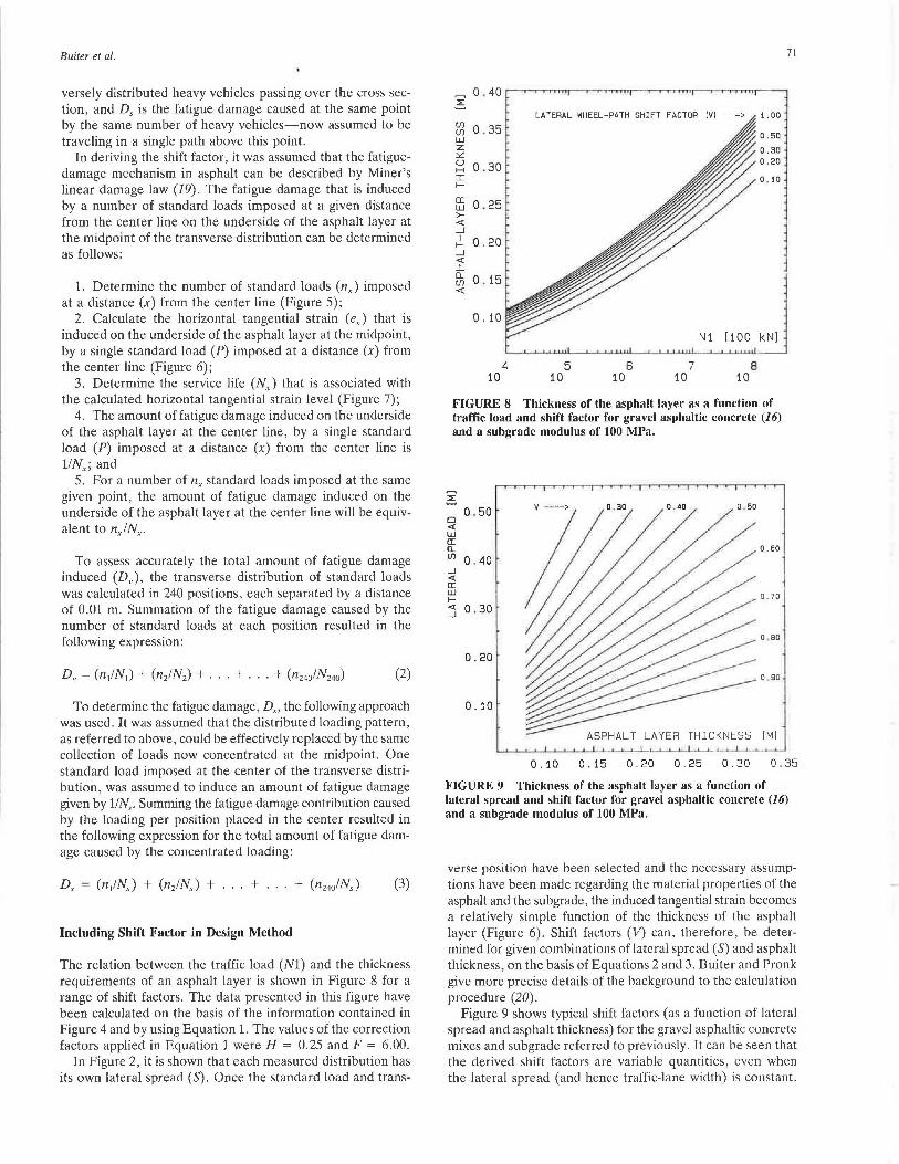
alculations were carried out with the BlSAR computer program (17) and the stiffness and fatigue properties found in the labor<Hory to determine the re lat i n betwee11 the design loading conditions ( 0) to be imposed and the requi red a ·phalt thickn ss . T hi is illu crated in f igure4. Th calculati n were performed assuming an air temperature of 14°C, a subgrade modulus of 100 MPa, the wheel configuration as described in the Shell method (18), and a standard axle load of 100 kN. To calculate the asphalt stiffness, the procedure described in the Shell method was used (18).
The following section describes how this information can be used to incorporate the shift fac tor into the design pr -cedure for selecting the correct layer thickness of an asphalt pavement.
Assumptions Made in Deriving Shift Factor
In deriving a design factor to account for lateral shifts of the wheel path, it was assumed that the transverse position of the wheels was independent of the wheel-load configuration. This assumption was necessary because data from axle-load measurements were not available . The passage of each wheel or wheel configuration was assumed to be equivalent to one standard load (in this case a point load) of a particular magnitude.
(J] 0 . 4 0 ~.-.--.-rm·o r--•- .-...,··r11 11 (J]
w z 0 . 35 CL u H 0 . 30 ;r: I-
a: 0.25 w >-<( 0 . 20 1 _J
I- 0 . 15 _J <( ;r: 0 . 10 Q_ (J] <(
NO [ 100 kN] 0.05 1 .aLI--• " " .. 1 ..... ~_._J
4 5 6 7 10 10 10 10 10
FIGURE 4 Thickness of the asphalt layer as a function of the design load.
8
TRANSPORTATION RESEARCH RECORD 1227
Furthermore, the following conditions were also assumed:
1. The transverse distribution of standard loads could be represented by a normal distribution (Figure 5);
2. The number of standard loads imposed at a distance (x) from the center of the transverse di tribution could be calculated from the normal distribution;
3. The full-depth asphalt pavement could be reduced to a two-layer linear elastic system (Figu1 ~ 6);
4. The horizontal tangential strain at the bottom of the asphalt layer could be regarded as the representative strain in pavement design; and
5. For asphalt, a relation exists between the induced horizontal tangential strain and the number of allowable load repetitions (Figure 7).
Derivation of Shift Factor
For the purpose of this paper, the shift factor (V) for fatigue damage has been defined as the quotient of D, and D,. D, equals the fatigue damage induced at a particular point on the underside of the flexible pavement by a number of trans-
t I
FIGURE 5 Transverse distribution of a given standard load.
PW -~---L ____ i[ __ _
LAYER THICKNESS
',, : ASPHALT PAVEMENT ', I
......... : ""' ...... : •x
SUBGRADE
FIGURE 6 Two-layer linear-elastic asphalt pavement
: 0~ TANGENTIAL STRAIN
DESIGN LOAD
FIGURE 7 Asphaltic concrete fatigue line (15).
Ruiter et al.
versely distributed heavy vehicles passing over the cross section, and Ds is the fatigue damage caused at the same point by the same number of heavy vehicles-now assumed to be traveling in a single path above this point.
In deriving the shift factor, it was assumed that the fatiguedamage mechanism in asphalt can be described by Miner's linear damage law (19). The fatigue damage that is induced by a number of standard loads imposed at a given distance from the center line on the underside of the asphalt layer at the midpoint of the transverse distribution can be determined as follows:
1. Determine the number of standard loads (nx) imposed at a distance (x) from the center line (Figure 5);
2. Calculate the horizontal tangential strain (ex) that is induced on the underside of the asphalt layer at the midpoint, by a single standard load (P) imposed at a distance (x) from the center line (Figure 6);
3. Determine the service life ( Nx) that is associated with the calculated horizontal tangential strain level (Figure 7);
4. The amount of fatigue damage induced on the underside of the asphalt layer at the center line, by a single standard load (P) imposed at a distance (x) from the center line is I/Nx; and
5. For a number of nx standard loads imposed at the same given point, the amount of fatigue damage induced on the underside of the asphalt layer at the center line will be equivalent to n)Nx.
To assess accurately the total amount of fatigue damage induced (Dv), the transverse distribution of standard loads was calculated in 240 positions, each separated by a distance of O.OI m. Summation of the fatigue damage caused by the number of standard loads at each position resulted in the following expression:
(2)
To determine the fatigue damage, D,, the following approach was used. It was assumed that the distributed loading pattern, as referred to above, could be effectively replaced by the same collection of loads now concentrated at the midpoint. One standard load imposed at the center of the transverse distribution, was assumed to induce an amount of fatigue damage given by I/N
5• Summing the fatigue damage contribution caused
by the loading per position placed in the center resulted in the following expression for the total amount of fatigue damage caused by the concentrated loading:
Ds = (n/Ns) + (n2/Ns) + ... + . · · + (n240/Ns) (3)
Including Shift Factor in Design Method
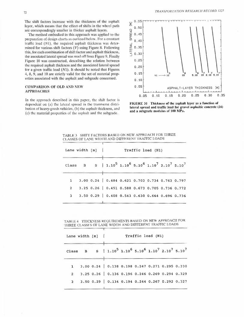
The relation between the traffic load (NI) and the thickness requirements of an asphalt layer is shown in Figure 8 for a range of shift factors. The data presented in this figure have been calculated on the basis of the information contained in Figure 4 and by using Equation I. The values of the correction factors applied in Equation I were H = 0.25 and F = 6.00.
In Figure 2, it is shown that each measured distribution has its own lateral spread (S). Once the standard load and trans-
~ 0 . 40
en 0 . 35 en lJ..I z ~ u 0 . 30 H I I-
a: 0 . 25 lJ..I >-<( _J I 0 . 20 I-
_J <( I 0.. 0 . 15 en <(
0. 10
10 4
LATERAL WHEEL-PATH SHIFT FACTOR (VI ---> I. 00
5 10
6 10
7 10
8 10
o .5o 0 .30 0.20
0 . 10
FIGURE 8 Thickness of the asphalt layer as a function of traffic load and shift factor for gravel asphaltic concrete (16) and a subgrade modulus of 100 MPa.
~ 0 . 50
D <( lJ..I a: D.. o .so en 0 . 40 _J <( a: lJ..I 0 . 70 I-<( 0 . 30 _J
0 . 80
0.20
0 90
0. 10
[M]
71
0.10 0.15 0.20 0.25 0.30 0 . 35
FIGURE 9 Thickness of the asphalt layer as a function of lateral spread and shift factor for gravel asphaltic concrete (16) and a subgrade modulus of 100 MPa.
verse position have been selected and the necessary assumptions have been made regarding the material properties of the asphalt and the subgrade, the induced tangential strain becomes a relatively simple function of the thickness of the asphalt layer (Figure 6). Shift factors (V) can, therefore, be determined for given combinations of lateral spread (S) and asphalt thickness, on the basis of Equations 2 and 3. Buiter and Pronk give more precise details of the background to the calculation procedure (20).
Figure 9 shows typical shift factors (as a function of lateral spread and asphalt thickness) for the gravel asphaltic concrete mixes and subgrade referred to previously. It can be seen that the derived shift factors are variable quantities, even when the lateral spread (and hence traffic-lane width) is constant.
72
The shift factors increase with th thi kne ·s of the asphalt layer, which mean thal the effect f hifls in the wheel path a r correspondingly ·mailer in thicker asphalt laye r .
T h · meth()d embodied in thi appr ach was applied to the preparation of design charts as outlined below. For a constant traffic load (Nl), the required asphalt thickness was determined for variou shift fact r (\/) using Figure 8. F llowing thi , for each combination of ·hi ft factor and a phall thickne s . the a ociated lateral spread wa.~ re;id off from Figure 9. Finally Figure JO was constructed, d cribing the re lation between the required as1 halt thickness and the associated lateral spr ad fo r a given traffic load (Nl). It hou ld be n ted that Figure 4, 8 9, and 10 are trictly valid for the ·et of materia l propertie associated with the a. phalt and . ubgrade concerned.
COMPARISON OF OLD AND NEW APPROACHES
In the approach described in this paper, the shift factor is dependent on (a) the lateral spread in the transverse distribution of heavy-goods vehicles, (b) the asphalt thicknes , and (c) the materia l properties of the asphalt and the subgrade.
~ 0 . 55 ~
0 . 50 0 <( w 0 . 45 a: Q_ (./) 0 . 40 _J <(
0 .35 a: w I-<( 0 . 30 _J
0 . 25
0.20
0 . 15
0 . 10
0 . 05
TRANSPORTATION RESEARCH RECORD 1227
5 NI ----> 10
7 7 7 10 2 . 10 5 . 10
ASPHALT-LAYER THICKNESS [M]
0 . 05 0 . 10 0 . 15 0.20 0.25 0.30 0 . 35
FIGURE 10 Thickness of the asphalt layer as a function of lateral spread and traffic load for gravel asphaltic concrete (1 6) and a subgrade modulus of 100 MPa.
TABLE 3 SHIFT FACTORS BASED ON NEW APPROACH FOR THREE CLASSES OF LANE WIDTH AND DIFFERENT TRAFFIC LOADS
Lane width [ rn] Traffic load (Nl)
Class B s I 1.105 i.10 6 5.10 6 1.107 2.10 7 5 . 10 7
1 3. 00 0.24 0.484 0 . 621 0 . 703 0.734 0.763 o. 797
2 3.25 0.26 0.451 0 . 588 0.673 0.705 0.736 o. 772
3 3.50 0.29 0.408 0.543 0.630 0.664 0.696 0.736
TABLE 4 THICKNESS REQUIREMENTS BASED ON NEW APPROACH FOR THREE CLASSES OF LANE WIDTH AND DIFFERENT TRAFFIC LOADS
Lane width [ rn] Traffic load (Nl)
Class B s I 1.105 i.10 6 5.106 1.107 2 . 107 5.107
1 3.00 0.24 0.138 0.198 0 . 247 0 . 271 0 . 295 0. 330
2 3.25 0.26 0.136 0.196 0.246 0. 2 69 0.294 0.329
3 3.50 0.29 0.134 0.194 0.244 0.267 0.292 0.327

Buiter et al.
In Table 3, the shift factors based on this approach are given for the three classes of traffic-lane width (Table 2) and for different traffic loads (Nl) . The thickness requirements for asphalt layers of roads with lane widths within the three classes have also been calculated on the basis of the new approach. These thicknesses are presented in Table 4 for different traffic loads (Nl). It can be seen that, for a given traffic load, only small differences exist in the thickness requirements among the three width categories.
In the Road and Hydraulic Engineering Division design method applied until recently, a constant (and therefore fundamentally incorrect) shift factor was used per traffic-lane width. This approach was based on the Shell method (18) and resulted in a constant shift factor of 0.40 being assumed for a traffic-lane width of 3.50 m. Table 5 gives the shift factors based on the old and new approaches for different traffic loads (Nl) and for lane-width Class 3 (Table 2). The thickness requirements for asphalt courses determined on the basis of the old approach are shown in Table 6, where they are compared with lane-width Class 3 values taken from Table 4.
As the traffic load (Nl) and, therefore, the thickness of the asphalt pavement increase, the difference in thickness requirements between the two methods becomes more apparent. It has been shown that, particularly in the case of heavily loaded motorways, the incorrect application of shift factors has led to significant deviations, as compared with the new approach. In the context of a general review, which aimed to bring theory and empirical method closer together, the approach described in this paper is one of the improvements that have been incorporated into the design method used by the Road and Hydraulic Engineering Division (21).
73
Even though the maximum difference of 22 mm (Table 6) is small when compared to the precision associated with other design parameters (for example, the standard deviation of the asphalt layer thickness is frequently greater than 10 to 15 mm) , the research reported in this paper has produced valuable information that also can be used in a more probabilistic approach to road design.
CONCLUSIONS AND RECOMMENDATIONS
The variable shift factor presented in this paper is dependent on the wheel-path shift pattern , the asphalt concrete thickness and the material properties of the asphalt concrete and the subgrade. Assessing the effects of lateral shifts in the wheel path by using a constant shift factor for a given width of traffic lane is, therefore, fundamentally incorrect.
Use of a constant shift factor of 0.40 for lane widths of 3.50 m can lead to considerable differences in the asphalt thickness requirements, when compared with the described method based on variable shift factors. In the case of motorways that are subject to heavy traffic loads, a first-order thickness difference is predicted , which is equivalent to incorrectly estimating the traffic load by a factor of 2.
It is recommended that design methods, based on a constant shift factor per traffic-lane width, should be changed and that consideration should be given to the new techniques that have been developed. These are felt to provide a better insight into the significance of such effects on the different types of construction.
TABLE 5 COMPARISON OF SHIFT FACTOR BASED ON NEW AND OLD APPROACHES FOR DIFFERENT TRAFFIC LOADS AND LANE WIDTH CLASS 3
Traffic load 1.105 1.106 5.106 1.107 2.107 5.107
New approach 0.408 0.543 0.630 0.664 0.696 0.736
Old approach 0.400 0.400 0.400 0.400 0.400 0 . 400
TABLE 6 COMPARISON OF THICKNESS REQUIREMENTS BASED ON NEW AND OLD APPROACHES FOR DIFFERENT TRAFFIC LOADS AND LANE WIDTH CLASS 3
New approach 0.134 0.194 0.244 0.267 0.292 0.327
Old approach 0.134 0.187 0.230 0.251 0.273 0.305
Difference 0.000 0.007 0.014 0.016 0.019 0.02 2
74
ACKNOWLEDGMENTS
This research project was conducted at the Road Engineering Branch, Road and Hydraulic Engineering Division. Appreciation is extended to all those who have in any way contributed to this project. More particularly, the authors want to thank J. H. Geerts, E. Vos, P. Hopman, and A. C. Pronk.
REFERENCES
1. J. T. Pauls. Transverse Distribution of Motor Vehicle Traffic on Paved Highways. Public Roads, Vol. 6, No. 1, 1925 , pp. 1-13.
2. A. Taragin. Effect of Roadway Width on Vehicle Operation . Public Roads, Vol. 24, No . 6, 1945, pp. 143-160.
3. A. Taragin. Driver Behavior Related to Types and Widths of Shoulders on Two-Lane Highways. Public Roads, Vol. 29, No. 9, 1957, pp. 197-205.
4. A. Taragin. Lateral Placements of Trucks on Two-Lane Highways and Four-Lane Divided Highways. Public Roads, Vol. 30, No. 3, 1958, pp. 71-75.
5. I. Scazziga. Effects of the Transverse Distribution of Heavy Loads on the Design of Flexible Pavements. Question II, Flexible Pavements, Switzerland. Presented at 15th PIARC World Road Congress, Mexico, 1975
6. W. Leutzbach, W. Maier, and M. Di:ihler. Untersuchung des Spurverhaltens von Kraftfahrzeugen auf Landstrassen durch Vervolgungsfahrten. Strasse und Autobahn, Vol. 8, 1981, pp. 301-304.
7. E. Mcsweeney. Wheelpath Distribution and Pavement Design. Intern Rapport 908, Vegdirektoratet Veglaboratoriet, Oslo, Norway, 1979.
8. J. H. Mathewson, R. Brenner, and R. J. Reiss. A Segmented Electrical Element for Detecting Vehicular Traffic. HRB Proc., HRB, National Research Council, Washington, D.C., 1949, pp. 374-383.
9. A. De Henau. Verkeersanalyse in bet kader van wegverhardingen. De Wegentechniek, Vol. 12 , No. 4. 1967, pp. 35-54.
10. I. Scazziga. Erhebungen iiber die Beanspruchung der Strassen durch sch were Motorwagen. Mitteilung No. 32. Institut fiir Stras-
TRANSPORTATION RESEARCH RECORD 1227
sen- , Eisenbahn- und Felsbau, Technische Hochschule. Ziirich , 1976.
11. A. Kasahare. Wheel Path Distribution of Vehicles on Highways. Proc., 1st International Symposium on Bearing Capacity of Roads and Airfields, Trondheim , Norway, 1982;·pp. 413-420.
12. K. Himeno, T. Watanabe, and T. Maruyama. Estimation of Fatigue Life of Asphalt Pavement. Proc., 6th International Conference on the Structural Design of Asphalt Pavements, Vol. 1, University of Michigan, Ann Arbor, 1987, pp. 272-289.
13. P. C. Hopman. Asphalt Fatigue Research: How and Why. Wegen, Vol. 61, No. 7/8, 1987 , pp. 26.'.l-268 (in Dutch).
14. J. H. Swart and A. E. van Dommelen. Design of Asphaltic Concrete Pavements of Motorways. Wegen, Vol. 62, No. 1, 1988, pp. 20-26 (in Dutch) .
15. F. Geysendorpher and P. C. Hopman. Fatigue Properties and Dynamic Stiffness Moduli of Gravel Asphaltic Concrete "Eisen 1978." Wegen, Vol. 61, No . 10, 1987, pp. 346-351 (in Dutch) .
16. Department of Public Works . "Eisen 1978": Requirements for Building Materials in Road Construction. Staatsuitgeverij, The Hague, 1978 (in Dutch) .
17. D. L. de Jong, M. G. F. Peutz, and A. R. Korswagen. Computer Program BISAR-Layered Systems Under Normal and Tangential Surface Loads. Koninklijke/Shell-Laboratorium, Amsterdam, External Report AMSR.006.73, 1973.
18. A. I. M. Claessen, J . M. Edwards, P. Sommer, and P. Uge. Asphalt Pavement Design-The Shell Method. Proc., 4th International Conference on the Structural Design of Asphalt Pavements, Vol. 1, University of Michigan , Ann Arbor, 1977, pp. 39-72.
19. M.A. Miner. Cumulative Damage in Fatigue. Journal of Applied Mechanics, Vol. 12, No. 3, 1945, pp . 159-164.
20. R. Buiter and A. C. Pronk. Mechanical Aspects of the Transverse Distribution of Heavy-Loads Vehicles. Report WXO-N-87-31. Road and Hydraulic Engineering Division. Ministry of Transport and Public Works, Delft, Netherlands, 1987 (in Dutch).
21. Road Engineering Manual-Pavement Design. Road and Hydraulic Engineering Division, Ministry of Transport and Public Works, Delft, Netherlands, Nov. 1987 (in Dutch).
Publication of this paper sponsored by Committee on Flexible Pavement Design.
![Untitled-6 [] yamato.pdf · tis 1390-2539 (1996) tis 1390-2539 (1996) tis 1227-2539 (1996) tis 1227-2539 (1996) tis 1227-2539 (1996) tis 1227-2539 (1996)](https://img.pdfslide.net/doc/110x75/5f7cd919128bf72d7a0d9590/untitled-6-yamatopdf-tis-1390-2539-1996-tis-1390-2539-1996-tis-1227-2539.jpg)