Embed Size (px)
Citation preview
Chapter 6
Efficiency Optimization of WDM-POF Network inShipboard Systems
Hadi Guna, Mohammad Syuhaimi Ab-Rahman,Malik Sulaiman, Latifah Supian, Norhana Arsad andKasmiran Jumari
Additional information is available at the end of the chapter
http://dx.doi.org/10.5772/53545
1. Introduction
Polymer optical fibers (POFs) are in a great demand for the transmission and processing ofoptical-based data communications compatible with the Internet, which is one of the fastestgrowing industries in automobile and domestic industry. Other industry such as aviationand maritime have also taking the advantages of POF. POFs become an alternative transmis‐sion media replacing copper cable for future shipboard networks. A proposed POF basedtechnology over submarine network for multimedia data transmission, measurement sys‐tem, navigation, sensors and several applications. As shown in Figure 1, the system is ableto transmit a number of signals represent a different data transmission (such as video, au‐dio, etc) using a WDM based network (refer to Figure 1).
In this chapter, we proposed a wavelength division multiplexing (WDM) system over POFdue to the rapid increase of traffic demands [2]. WDM is the solution that allows the trans‐mission of data in onboard the ship over more than just a single wavelength (color) and thusgreatly increases the POF's bandwidth.
2. Fiber optic onboard ship
The utilization of optical fiber as major data communication media onboard ship especiallyon naval combatant ships is not a new discovery [1,2]. Equipments such as communicationssystem, radars, navigation system, combat management system, platform monitoring sys‐
© 2013 Guna et al.; licensee InTech. This is an open access article distributed under the terms of the CreativeCommons Attribution License (http://creativecommons.org/licenses/by/3.0), which permits unrestricted use,distribution, and reproduction in any medium, provided the original work is properly cited.

tems and LAN network have used fiber optic to transfer high rate data within equipment oras main data communication backbone. For instant, the platform control and monitoringsystem onboard ship is using dual redundancy Fiber Data Distribution Integration (FDDI)system to command, control and monitor the platforms onboard the ship. An example ofFDDI architecture is shown in Figure 2. This FDDI architecture topology is glass fiber basedthat capable to transport high density data over long distance because the backbone is cov‐ering the entire ship. Numbers of commercial ships are also using FDDI topology as it is aproven system available commercially in the market [1-4].
Figure 1. WDM-POF based network over novel system has been propose to ensure the high quality data transmissionand communication system
In this chapter, the novel optical splitter/coupler based polymer optical fiber (POF) was suc‐cessfully designed for the infotainment and data communication system over POF on-ship.The optical splitter consists of a single input port and N of output port (N=2,3,4,....). In prin‐ciple, the bidirectional splitter performs two operational functions; either signal coupling (inmultiple P2P direction) or signal splitting (in P2M direction). Thus, the usage of WDM on‐board ship will become a new frontier in optical network.
This fiber optic onboard ship system is the most updated and promising innovation that willrevolutionize in-vehicle data communication system which all data can be simply sent in visi‐ble light format rather than in electrical format at high speed data transmission. Data commu‐nication system is such all-in-one communication media system and the latest trend onboard
Current Developments in Optical Fiber Technology162
ship network in which many appliances such as navigation system, platform surveillance &monitoring system, damage control & fire fighting system, onboard infotainment & training,sensors and many other appliances can be integrated via a WDM-POF. With this WDM-POF-based technology, all data such can be processed with environment-friendly LED conversionand low-cost multiplexing and filtering method besides the fact that it can extend the numberof appliances in car interior. This invention enables simple POF cabling system for deliveringeach optical data as POF is the most updated cabling technology replacing conventional cop‐per wire for short-haul communication. The advantages offered by POF over copper wire;economical installing cost, enabling eco-friendly LED conversion, Electromagnetic Interfer‐ence (EMI) immunity, no grounding necessary, avoiding sparks, resistance to heat and vibra‐tion, lighter material, and narrow bending radius.
During the implementation of this project, several research activities to improve the efficien‐cy of the system has been conduct. Temperature plays a significant role which can influencethe performance of the data communication system in POF-based onboard ship. The charac‐terization test was carried out is to determine the performance of the device in the test benchnetwork. In the meantime, the fabricated splitter has been compared to other commercial one,in term of their performance; splitting ratio and power loss. An experiment has been set up inSPECTECH lab, Universiti Kebangsaan Malaysia, to evaluate the survivability of the device inenvironmental condition with varied temperature. Besides, the aim of experiment is to ob‐serve the temperature stability of the device while performing splitting/coupling function.The variation of temperature from 30 °C to 125 °C was exposed directly to the device.
In response to feedback from industries, the thermal aging experiment was undertaken toevaluate the durability of the device in very high temperature environment. The experimentwas carried out within 9 hours while the device was exposed to high temperature at 105 °C.An analysis was made to observe the device performance with the variation of temperature.Several graph was plotted to analyze power loss and coupling ratio in varied temperature.
3. Results and discussion
In this study, single line POF is used to carry multiple wavelengths using WDM technologytaking the advantage of its cheaper materials and fragility. Four different wavelengths areused to connect LAN connections, telephone line, surveillance cameras and central video/audio entertainments network throughout the ship for access by the user. The controller andserver for ship LAN and surveillance cameras is at Machinery Control Room (MCR) that lo‐cated at deck 1 aft of the ship. This is also the location of damage control and fire fightingheadquarters onboard. The telephone PABX and central video/audio entertainment networkcontroller is at Main Communication Center located at the centre of the ship on deck 1. Thesystems are also able to be monitored and controlled from the bridge located at 01 deckwhere the ship is navigated or from the combat Information Centre (CIC) where the shipwarfare tactical information and status is collected, displayed, evaluated, disseminated andcontrolled for decision by the Commanding Officer.
Efficiency Optimization of WDM-POF Network in Shipboard Systemshttp://dx.doi.org/10.5772/53545
163

Figure 2. L3 Dual Redundant FDDI for Ship Control and Monitoring architectural network
The CCTV will provide surveillance and monitoring from flood, fire or unauthorized en‐trance of the high value compartments onboard. The LAN will enable ship staff to access alladministration and orders, manuals, publications, maintenance requirements and trainingdocument from offices, common area and cabins. The central video/audio entertainmentsnetwork is providing the ships’ crews with central entertainment such as ship’s live radio,movies and news broadcasted throughout the ship. The controller is placed at ship’s mainbroadcast & recreation centre. The suggested backbone topology throughout the ship is asshown in Figure 3.
Each deck are interconnected to form a Dual Redundant POF-WDM (DRePOF-WDM) back‐bone arranged as one ring that interconnected to the equipments and end user devices. Thebackbone is arranged in mesh topology via an Optical Add Drop Multiplexer (OADM)which acts as optical switches. These switches will be able to be controlled and monitored atMCR, CIC or bridge for redundant connection through the backbone to ensure survivabilityand interconnectivity of the network. The connection [5] is shown in Figure 4. The devicesneed for this system is: fiber couplers, Multiplexer, Demultiplexer, Optical Add Drop Multi‐plexer (OADM) and POF's switches.
Figure 4 as shown above indicates overall arrangement of the system from the backbone tothe equipments and the end users located on the various decks onboard the ship. On eachdeck, equipments and users in the rooms or compartments is linked to the DRePOF-WDMbackbone topology using WDM sequenced by time division multiplexing TDM via a trans‐
Current Developments in Optical Fiber Technology164

ceiver. The multiple different signals enter and exit from the devices onto the single wave‐length data streams are done by passive devices multiplexer and demultiplexer. Manytransmitters with different lights colour are used to carry single information. For example,red light with 650nm wavelength modulated with LAN signal while blue, green, and yellowlights carry image information, radio frequency (RF), and video signal, respectively. Asshown is Figure 4, WDM is the first passive device required in WDM-POF system and itfunctions to combines optical signals from multiple different single-wavelength end devicesonto a single fiber [6-7]. Conceptually, the same device can also perform the reverse processwith the same WDM techniques, in which the data stream with multiple wavelengths de‐composed into multiple single wavelength data streams, called demultiplexing.
Figure 3. Deck-by-deck dual redundant POF-WDM backbone architectural network
Efficiency Optimization of WDM-POF Network in Shipboard Systemshttp://dx.doi.org/10.5772/53545
165

Figure 4. Connection from DRePOF-WDM backbone to each deck and equipments
During the development of the onboard project, several research activities to improve theefficiency of the system has been conduct. The characterization test was carried out is to de‐termine the performance of the device in the test bench network.
3.1. Design and characterization of POF splitter
3.1.1. First generation
The first generation of low-cost fused taper (LFT™) splitters is initially demonstrated asnovel innovation in optical splitter technology particularly for POF since it is fabricated viahandmade fusion technique that is performed by handwork skill associated with simpletools; candle and metal rather than biconical fused taper. The fabrication method is cost-ef‐fective and less time-consuming (11 minutes per unit).
In comparison, the first generation of LFT™ splitter is more cost-effective than other POF-based commercial splitter e.g. Diemount™ grinded splitter, Harz-optic™ splitter, IndustrialFiber Optic™ (IFO) Fused Splitter and many others. The high costs of these commercialsplitters are mainly due to the fabrication method that is complicated and implemented withfabrication machine that expensive. For LFT™ splitters, new handwork fusion method lead
Current Developments in Optical Fiber Technology166

to low fabrication cost of splitter. The price for IFO™ fused splitter which uses same type asLFT™ splitter cost around USD110 while LFT™ splitter is only cost at ~ USD20. Figure 5shows the price comparison between the commercial splitter and LFT™ splitters.
Figure 5. The price comparison between the commercial splitters (a) Industrial Fiber Optic™ (IFO) Fused Splitter (b)Diemount™ grinded splitter, (c) Harz-optic™ splitter, and (d) LFT™ splitters which cost at USD110, USD90, USD50 andUSD20, respectively
3.1.2. Second generation
The second generation of LFT™ splitter is the successor of poor-performance fused splitter(first generation). The splitter is remain fabricated through handwork fusion technique.However, the procedures of fabrication method is changed with minor modification where‐by the method include a new step particularly for the purpose of fusing the polymer fibers.As shown in Figure 6(a), second generation of LFT™ splitter is designed to have small areaof POF imperfection, in which the length of fused and tapered fibers is reduced below 4 cm.The multimode step-indexed polymethylmethacrylate (PMMA) POF having a core diameter of1 mm is used for splitter fabrication. Besides, polyvinyl chloride (PVC) is another materialthat used as jacket for insulating input and output fiber ports of fused splitter.
In the splitter, the tapered structure is the most critical region in producing low-loss and ex‐cellent power-splitting device. The structure has to be designed and fabricated having highfusion degree, in which all POFs are completely fused and coupled so that the wavelengthof interest can pass through the coupling region with low power deviation and excellentpower-splitting ratio. Therefore, no twisting effetcs are present in tapered region since thetwisted spiral fiber is refined via fusion process. Figure 6(b) shows the cross-section of high‐ly fused region in 3 × 3 or/and 1 × 3 tree coupler (splitter). Through fused and pulled region
Efficiency Optimization of WDM-POF Network in Shipboard Systemshttp://dx.doi.org/10.5772/53545
167

having a cross-section as depicted in Figure 6(b), the optical power input is coupled to eachfiber output port with excellent power-splitting ratio. In the other word, one third of powercapacity is distributed to every single of output fiber port.
Figure 6. New schematic design of (a) highly-fused taper structure in the center of fiber bundle and (b) cross-sectionof fused region in fused 3 × 3 biconical coupler
Basically, the term of ‘fusion’ defines the act or procedure of liquefying or melting by the ap‐plication of heat. The maximum temperature required to ensure POFs reach melting point is85°C [6]. In general, the technique includes four processes; fiber bundle configuration, fabri‐cation of spiral fiber, fusion and fiber tapering. Among these process, fusion is new step thatfirstly demonstrated in fabrication method for the second generation splitters.
a. Fiber bundle configuration
b. Fabrication of spiral fiber
c. Fusion
d. Fiber tapering
Since the length of tapered fiber is reduced below 6 cm to minimize area of POF imperfec‐tion. An experimental characterization was undertaken on the relationship between thelength of tapered and optical loss to observe a possible range of tapered length enablinglow-loss power splitting. Figure 7 shows the relationship between the length of tapered andoptical loss. Figure 8 shows the relationship between coupling ratio and the length of ta‐pered. These results are essential in determine excellent dimension for the fabrication of sec‐ond generation of LFTTM splitter. Coupling ratio is a parameter that indicates fusion
Current Developments in Optical Fiber Technology168

characteristic in fused fibers. The ideal coupling ratio is 0.33 for each output port of splitter.The coupling ratio of 0.33 for each port shows that each fiber has been fused completely tobe as a new single core.
Figure 7. The excess loss of 3 × 3 coupler with range of tapered length vary from 1.5 cm to 7.5 cm; low excess loss < 3dB occur in coupler in the range of tapered fiber length of 1.5 – 3.0 cm.
Figure 8. The coupling ratio of 3 × 3 coupler with range of tapered length vary from 1.5 cm to 7.5 cm; the coupler hasgood coupling ratio (~ 0.33) for each port within the range of 3 cm to 1.5 cm
Efficiency Optimization of WDM-POF Network in Shipboard Systemshttp://dx.doi.org/10.5772/53545
169

From the graph, it is indicated that low optical loss < 3dB presents in tapered fiber lengthrange of 1.5 – 3.0 cm. Furthermore, the fused and tapered fiber has good fusion characteris‐tic in the range of 1.5 – 2.0 cm since the coupling ratio of each output fiber reach ~ 0.33 with‐in this range. It is found that 1.5 cm is the minimum length required for fused input fiber tobe suited into a small channel having ~1 mm diameter in DNP connector. Therefore, therange of 1.5 – 2.0 is selected for excellent dimension of fused and tapered length in order topermit low-loss power splitting and homogenous splitting ratio. Figure 9 (a) shows thestructure of fused and tapered output fiber featured in the second generation of LFTTM split‐ter, in which the diameter of POF cross-section decrease to ~1 mm that fabricated throughmodified handwork fusion technique.
Figure 9. The features of (a) novel highly fused tapered having short taper length and plane surface (without twistingeffect) and (b) conventional fused taper having long taper length and ripple surface (with twisting effects)
Figure 10. The results of experimental optical injection with 650 nm light source; (a) for the first generation of splitterand (b) for the second generation of LFTTM splitter.
Current Developments in Optical Fiber Technology170
As shown in Figure 10 (a), when the only one fused input port is injected with red LEDtransmitter having 650 nm, it is observed that each output port emits high-intensity redlight. In comparison, as shown in Figure 10 (b), in the past experimental injection test, eachoutput port of the first generation splitter emits red light with low power intensity exceptone output fiber among them. The power splitting with high intensity shows that the secondgeneration of fused splitter is able to perform low-loss optical data splitting.
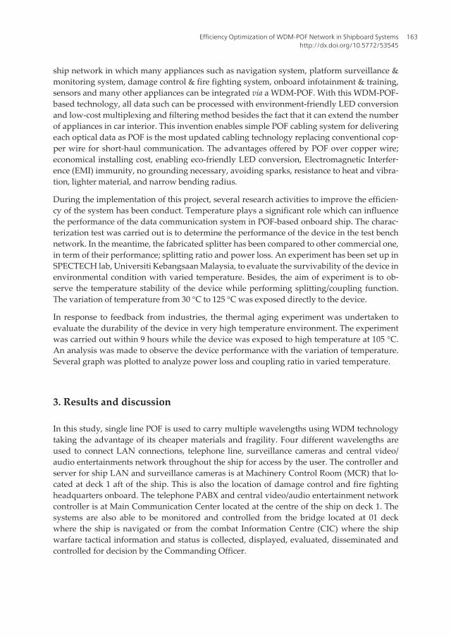
For the first generation splitters, as shown in Figure 11, the insertion loss of each output portis high which the range is 10 - 20 dB. In contrast to the first generation splitter, the secondgeneration splitters perform with low insertion loss since each output fiber has insertion lossvarying from 4 dB to 17 dB.
Figure 11. The comparison for insertion loss of each output fiber
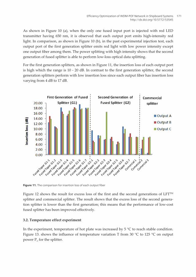
Figure 12 shows the result for excess loss of the first and the second generations of LFTTM
splitter and commercial splitter. The result shows that the excess loss of the second genera‐tion splitter is lower than the first generation; this means that the performance of low-costfused splitter has been improved effectively.
3.2. Temperature effect experiment
In the experiment, temperature of hot plate was increased by 5 °C to reach stable condition.Figure 13. shows the influence of temperature variation T from 30 °C to 125 °C on outputpower Po for the splitter.
Efficiency Optimization of WDM-POF Network in Shipboard Systemshttp://dx.doi.org/10.5772/53545
171
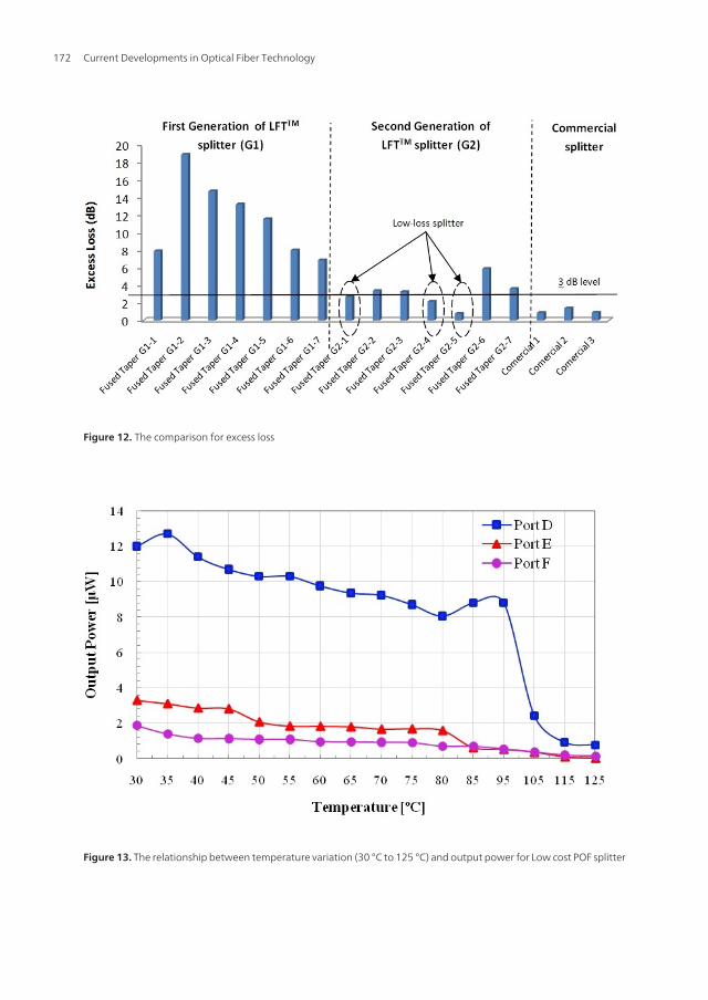
Figure 12. The comparison for excess loss
Figure 13. The relationship between temperature variation (30 °C to 125 °C) and output power for Low cost POF splitter
Current Developments in Optical Fiber Technology172

As shown in Figure 14, in each fiber port, output power decreases with respect to tempera‐ture rise. The type of fused polymer splitters were completely damaged when heating tem‐perature increased T = 125 °C. The temperature point at 95 °C can thus be defined asdamage threshold because the splitter loss temperature stability at this point. Figure 14.shows Excess loss variations as function of temperature for the splitter in bidirectional pow‐er injection.
As shown in Figure 15, the excess loss increase gradually with temperature increase. In thiscase, the splitter has temperature stability while maintaining their performance until T = 100°C. Figure 15. shows temperature dependence of coupling ratio for the splitter in theirthroughput and cross-coupled fiber ports in bidirectional light guide propagation.
3.3. Thermal aging experiment
Figure 16. shows the durability of the Low cost POF splitter within 9 hours at fixed tempera‐ture T = 105 °. The graph shows that the splitter has high temperature stability within 9hours when the splitter was exposed to very high temperature. The result shows that thesplitter has high durability.
Figure 17. shows the durability of the Low cost POF splitter in term of output power in μWwithin 9 hours at fixed temperature T = 105 °.
Figure 14. Excess loss variations as function of temperature for the splitter in bidirectional power injection
Efficiency Optimization of WDM-POF Network in Shipboard Systemshttp://dx.doi.org/10.5772/53545
173
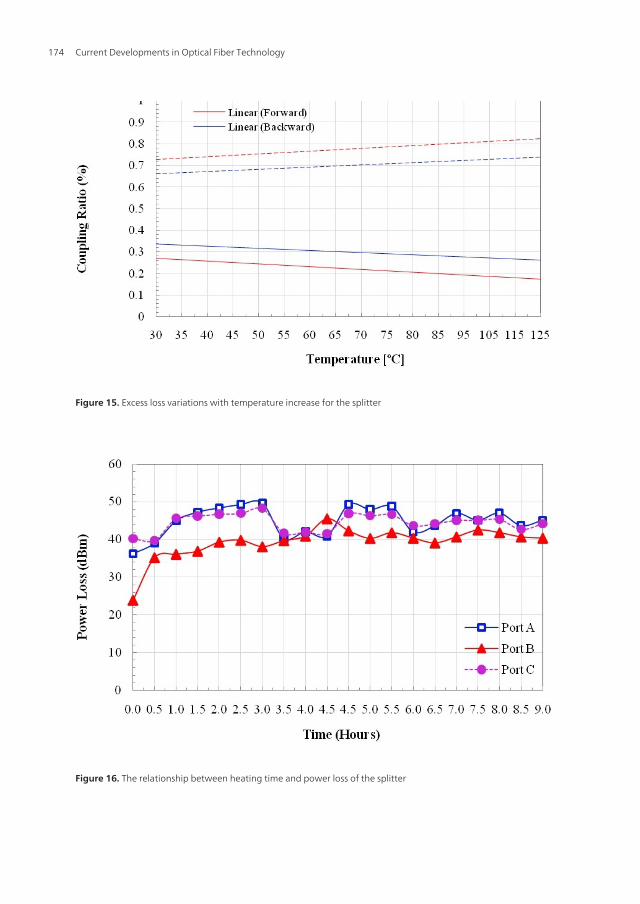
Figure 15. Excess loss variations with temperature increase for the splitter
Figure 16. The relationship between heating time and power loss of the splitter
Current Developments in Optical Fiber Technology174
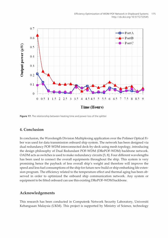
Figure 17. The relationship between heating time and power loss of the splitter
4. Conclusion
In conclusion, the Wavelength Division Multiplexing application over the Polimer Optical Fi‐ber was used for data transmission onboard ship system. The network has been designed viadual redundancy POF-WDM interconnected deck-by-deck using mesh topology, introducingthe design philosophy of Dual Redundant POF-WDM (DRePOF-WDM) backbone network.OADM acts as switches is used to make redundancy circuits [5, 8]. Four different wavelengthshas been used to connect the overall equipments throughout the ship. This system is verypromising hence the payback of less overall ship’s weight and therefore will improve thespeed and less fuel consumptions of the ship for future new build or ship embarking life exten‐sion program. The efficiency related to the temperature effect and thermal aging has been ob‐served in order to optimized the onboard ship communication network. Any system orequipment to be fitted onboard can use this existing DRePOF-WDM backbone.
Acknowledgements
This research has been conducted in Computer& Network Security Laboratory, UniversitiKebangsaan Malaysia (UKM). This project is supported by Ministry of Science, technology
Efficiency Optimization of WDM-POF Network in Shipboard Systemshttp://dx.doi.org/10.5772/53545
175
and Environment, Government of Malaysia, PRGS/1/11/TK/UKM/03/1. All of the handmadefabrication method of POF splitter, LFTTM splitter and also the low cost WDM-POF networksolution were protected by patent numbered PI2010700001.
Author details
Hadi Guna, Mohammad Syuhaimi Ab-Rahman, Malik Sulaiman, Latifah Supian,Norhana Arsad and Kasmiran Jumari
Universiti Kebangsaan Malaysia, Selangor Darul Ehsan, Malaysia
References
[1] Gopalkrishna, D.H., S.R. Muthangi, Vinayak, A. Paulraj. FDDI-A high speed datahighway for warship system integration 1991, MILCOM '91.
[2] Gotthardt, M.R., K. Kathiresan, G.H. Campbell, J. Fluevog. Shipboard Fiber OpticTransmission Media (Cables). AT&T Bell Labs, AT&T Federal Systems and AT&TNetworks Systems. CH2681-5/89/0000-0235 IEEE (1989): 0235.
[3] Baldwin, C., J. Kiddy, T. Salter, P. Chen, J. Niemczuk. Fiber Optic Structural HealthMonitoring System: Raugh Sea Trials of the RV Triton 2002. Ocean MTS/IEEE.
[4] Jessop, Clifford N. All-Optical Wavelength Conversion in a Local Area Network, Re‐port to United States Naval Academy Trident Scholar Committee, May 2006.
[5] Mohamad Syuhaimi Ab-Rahman, Mohamad Najib Mohamad Saupe, Kasmiran Ju‐mari. Optical Switch Controller Using Embedded Internet Based System 2009. Inter‐national Conference on Computer Technology and Development.
[6] Imran Ahmed, Hong Wong and Vikram Kapila. Internet-Based Remote Control us‐ing a Microcontroller and an Embedded Ethernet, Proceeding of the American Con‐trol Conference: 2004.
[7] Hong Wong and Vikram Kapila. Internet-Based Remote Control of a DC Motor usingan Embedded Microcontroller 2004, Proceeding of the American Society for Engi‐neering Education annual Conference and Exposition.
[8] Alam, M.F., M. Atiquzzaman, B. Duncan, H. Nguyen, R. Kunath. Fibre-optic networkarchitectures for on-board radar and avionics signal distribution. IEEE Radar Confer‐ence, Washington, DC, 7-12 May, 2000.
Current Developments in Optical Fiber Technology176