Embed Size (px)
Citation preview
Energy EfficientData Center Design g
Can Ozcan | Ozen Engineering
k |© 2011 ANSYS, Inc. August 25, 20111
Emre Türköz | Ozen Engineering
BioCan Ozcan received his Master of Science in Mechanical Engineering from Bogazici
University of Turkey in 2005, which involved fracture mechanics of thin films using Ansys Mechanical software. g y
Mr. Ozcan has been involved in CAE consulting and technical support using Ansys software for 6 years with Ozen Engineering in Silicon Valley; specifically working on Applied Mechanics problems.working on Applied Mechanics problems.
During the past 6 years he has been involved in simulation work for mostly electronics and biomedical industry, where he has developed custom material models scripts for modeling and took part in software development in CAEmodels, scripts for modeling and took part in software development in CAE field
Mr. Ozcan has presented at international conferences in Europe and America and has published 6 articles on various simulation related topicshas published 6 articles on various simulation related topics.
© 2011 ANSYS, Inc. August 25, 20112

Ozen Engineering Inc
We are the local ANSYS channel partner
With over 25 years of experience in Finite Elements Simulations and Engineering Consulting, we collaborate with customers to provide the best in class expertise and solutions to their problems, enabling them to succeed.
i
© 2011 ANSYS, Inc. August 25, 20113
www.ozeninc.com
Main Guides
Build the Best Data Facility for Your Business, by Dougles Alger
The Dell Smart Solution Advisor for data centersThe Dell Smart Solution Advisor for data centers
© 2011 ANSYS, Inc. August 25, 20114
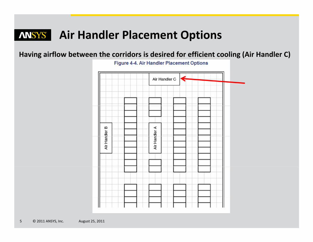
Air Handler Placement OptionsHaving airflow between the corridors is desired for efficient cooling (Air Handler C)
© 2011 ANSYS, Inc. August 25, 20115
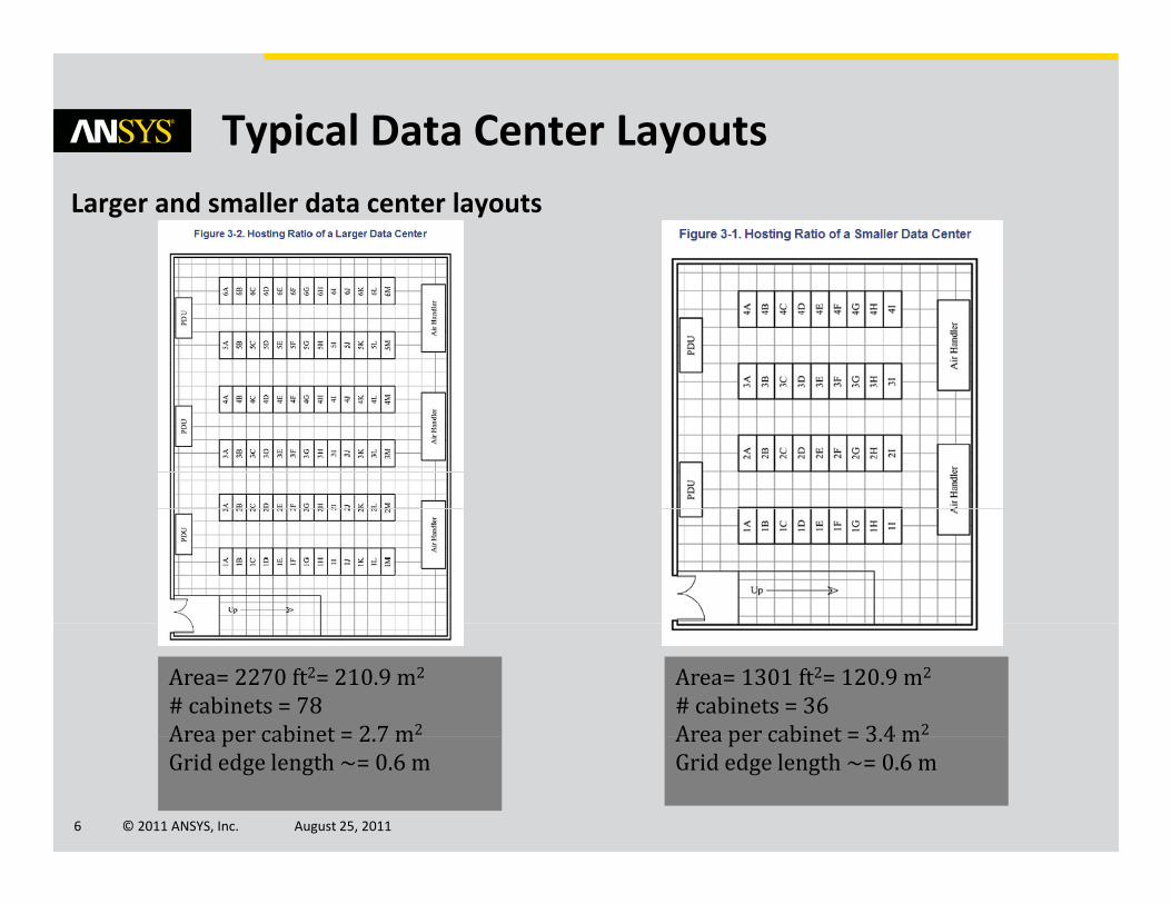
Typical Data Center LayoutsLarger and smaller data center layouts
Area= 1301 ft2= 120.9 m2
# cabinets = 36Area per cabinet = 3 4 m2
Area= 2270 ft2= 210.9 m2
# cabinets = 78Area per cabinet = 2 7 m2
© 2011 ANSYS, Inc. August 25, 20116
Area per cabinet = 3.4 mGrid edge length ~= 0.6 m
Area per cabinet = 2.7 mGrid edge length ~= 0.6 m
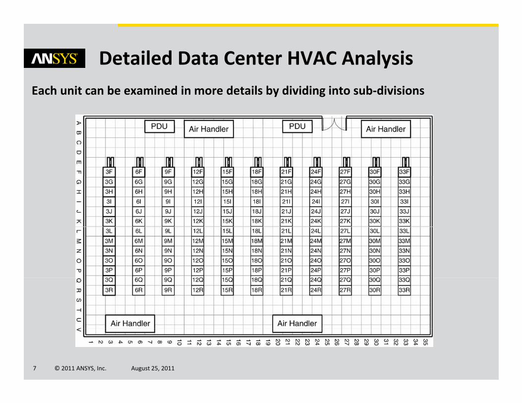
Detailed Data Center HVAC AnalysisEach unit can be examined in more details by dividing into sub‐divisions
© 2011 ANSYS, Inc. August 25, 20117
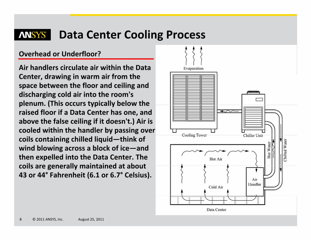
Data Center Cooling ProcessOverhead or Underfloor?
Air handlers circulate air within the Data C t d i i i f thCenter, drawing in warm air from the space between the floor and ceiling and discharging cold air into the room's plenum. (This occurs typically below theplenum. (This occurs typically below the raised floor if a Data Center has one, and above the false ceiling if it doesn't.) Air is cooled within the handler by passing over coils containing chilled liquid—think of wind blowing across a block of ice—and then expelled into the Data Center. The coils are generally maintained at aboutcoils are generally maintained at about 43 or 44° Fahrenheit (6.1 or 6.7° Celsius).
© 2011 ANSYS, Inc. August 25, 20118
Overhead or Underfloor?• Underfloor is harder to install, might need a ramp at the entrance, more
expensive
O h d i i d h h t i t ll• Overhead is easier and much cheaper to install.
ButBut,
‘’It is significantly more difficult to cool a server environment by pushing cold air downward’’
So, if our concern is the energy‐efficiency, we should simulate an underfloorsimulation.
© 2011 ANSYS, Inc. August 25, 20119
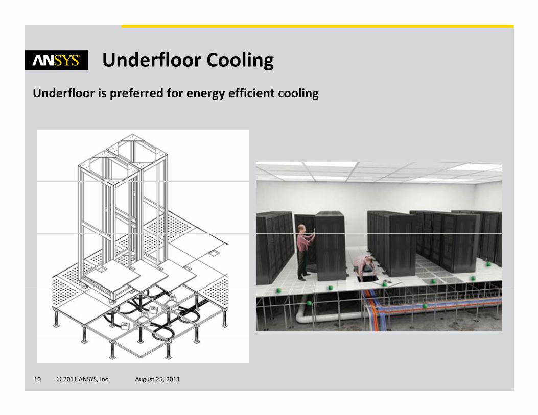
Underfloor CoolingUnderfloor is preferred for energy efficient cooling
© 2011 ANSYS, Inc. August 25, 201110
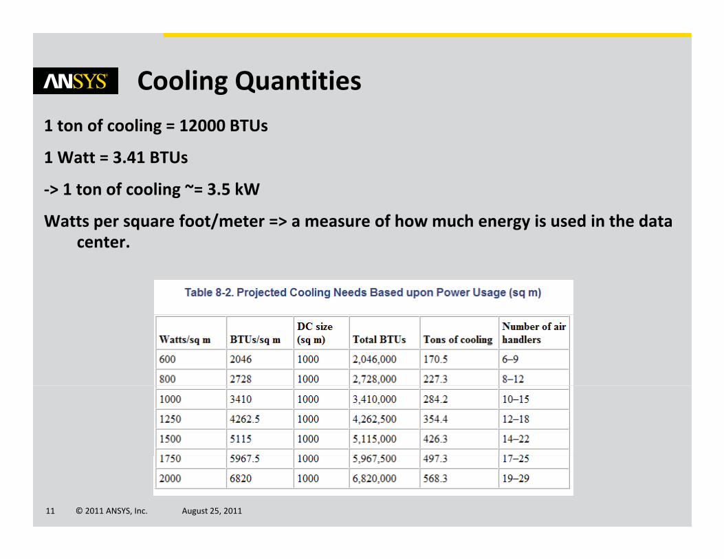
Cooling Quantities1 ton of cooling = 12000 BTUs
1 Watt = 3.41 BTUs
‐> 1 ton of cooling ~= 3.5 kW
Watts per square foot/meter => a measure of how much energy is used in the data centercenter.
© 2011 ANSYS, Inc. August 25, 201111
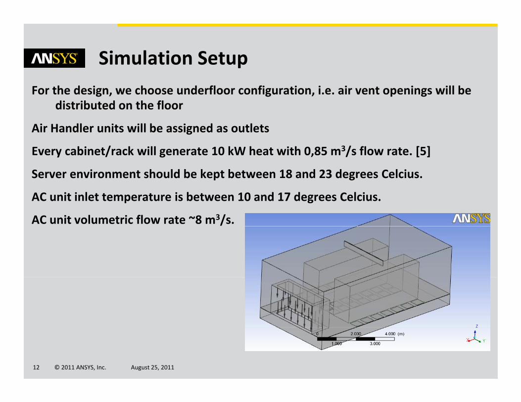
Simulation SetupFor the design, we choose underfloor configuration, i.e. air vent openings will be
distributed on the floor
Ai H dl it ill b i d tl tAir Handler units will be assigned as outlets
Every cabinet/rack will generate 10 kW heat with 0,85 m3/s flow rate. [5]
Server environment should be kept between 18 and 23 degrees CelciusServer environment should be kept between 18 and 23 degrees Celcius.
AC unit inlet temperature is between 10 and 17 degrees Celcius.
AC unit volumetric flow rate ~8 m3/s.
© 2011 ANSYS, Inc. August 25, 201112
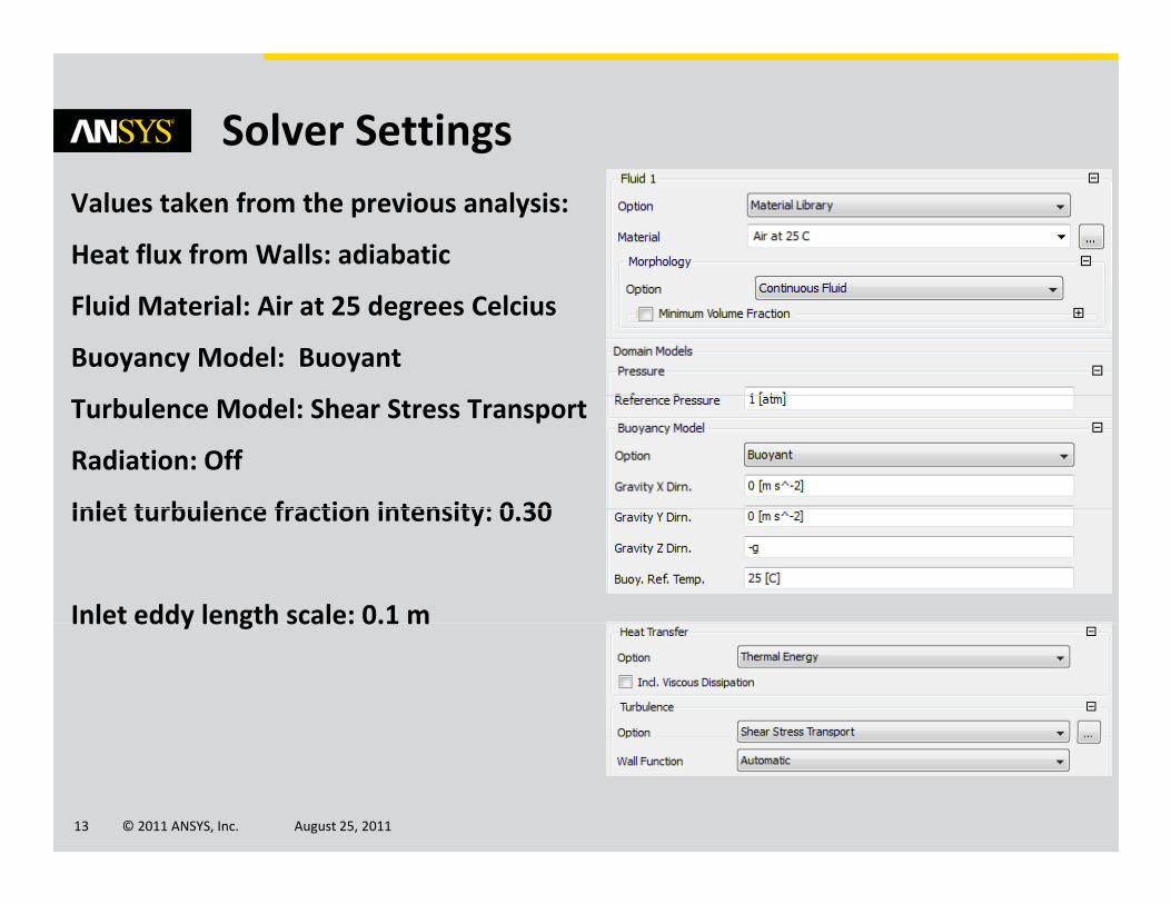
Solver SettingsValues taken from the previous analysis:
Heat flux from Walls: adiabatic
Fluid Material: Air at 25 degrees Celcius
Buoyancy Model: Buoyant
Turbulence Model: Shear Stress Transport
Radiation: Off
Inlet turbulence fraction intensity: 0 30Inlet turbulence fraction intensity: 0.30
Inlet eddy length scale: 0.1 mInlet eddy length scale: 0.1 m
© 2011 ANSYS, Inc. August 25, 201113
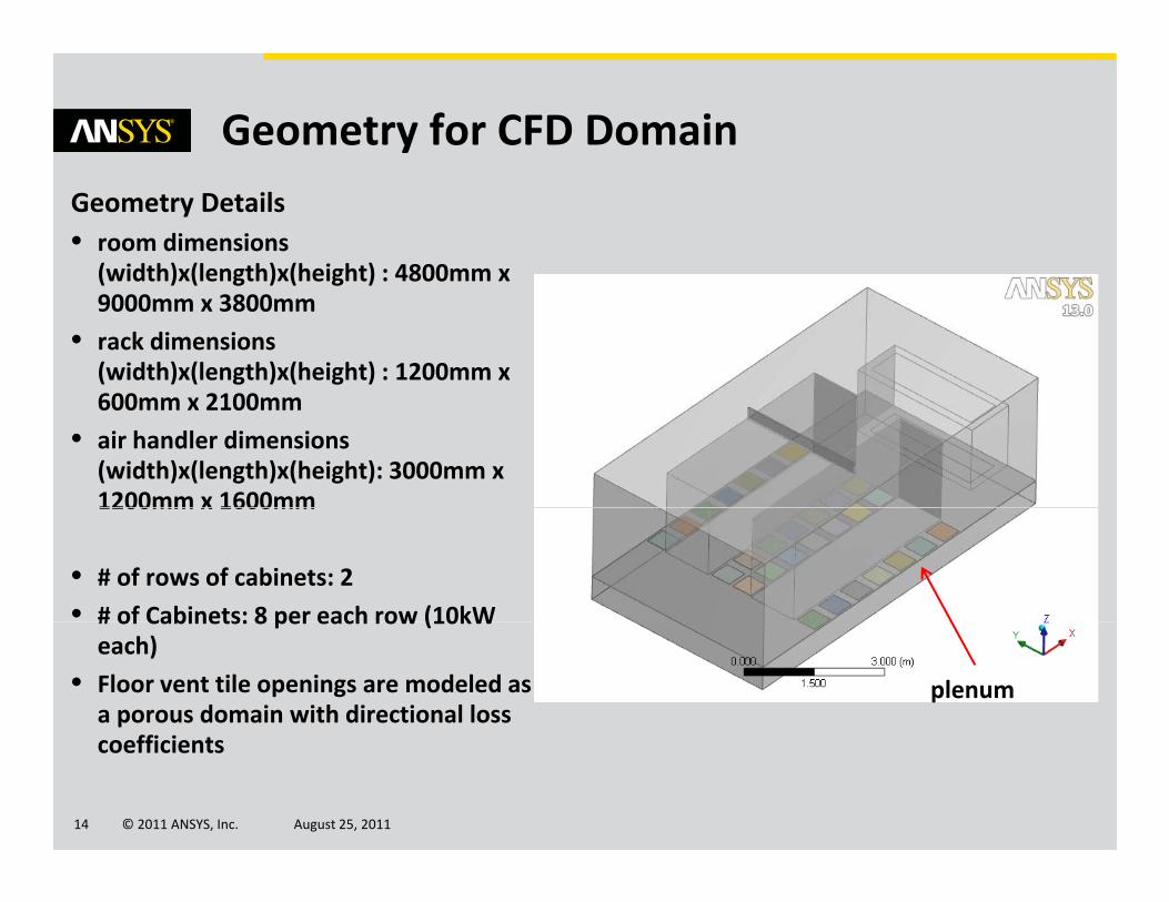
Geometry for CFD DomainGeometry Details• room dimensions (width)x(length)x(height) : 4800mm x(width)x(length)x(height) : 4800mm x 9000mm x 3800mm
• rack dimensions (width)x(length)x(height) : 1200mm x 600 2100600mm x 2100mm
• air handler dimensions (width)x(length)x(height): 3000mm x 1200mm x 1600mm1200mm x 1600mm
• # of rows of cabinets: 2
• # of Cabinets: 8 per each row (10kW# of Cabinets: 8 per each row (10kW each)
• Floor vent tile openings are modeled as a porous domain with directional loss
ffi i
plenum
© 2011 ANSYS, Inc. August 25, 201114
coefficients
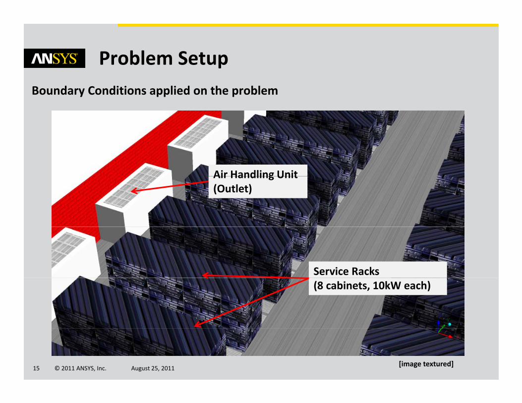
Problem SetupBoundary Conditions applied on the problem
Air Handling UnitAir Handling Unit(Outlet)
Service Racks(8 cabinets, 10kW each)
© 2011 ANSYS, Inc. August 25, 201115[image textured]
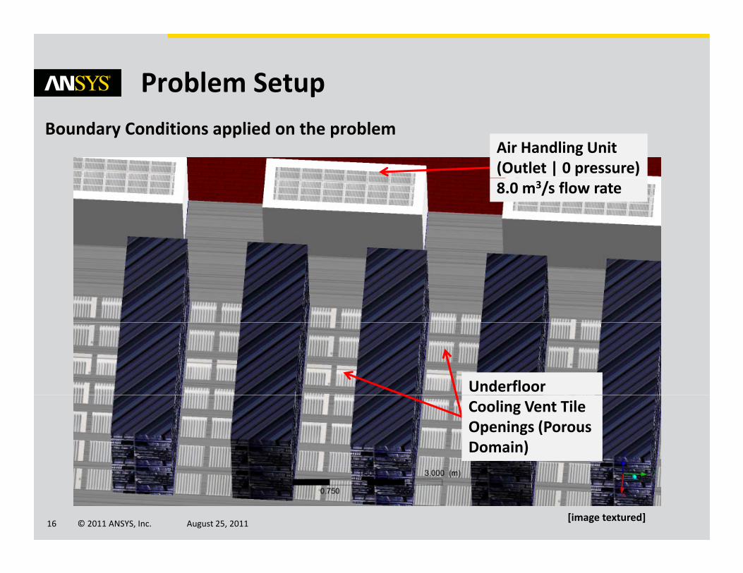
Problem SetupBoundary Conditions applied on the problem
Air Handling Unit(Outlet | 0 pressure)8.0 m3/s flow rate
UnderfloorCooling Vent Tile Openings (Porous Domain)
© 2011 ANSYS, Inc. August 25, 201116[image textured]
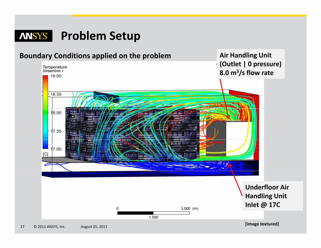
Problem SetupBoundary Conditions applied on the problem Air Handling Unit
(Outlet | 0 pressure)8.0 m3/s flow rate
Underfloor Air Handling Unit l @
© 2011 ANSYS, Inc. August 25, 201117
Inlet @ 17C
[image textured]
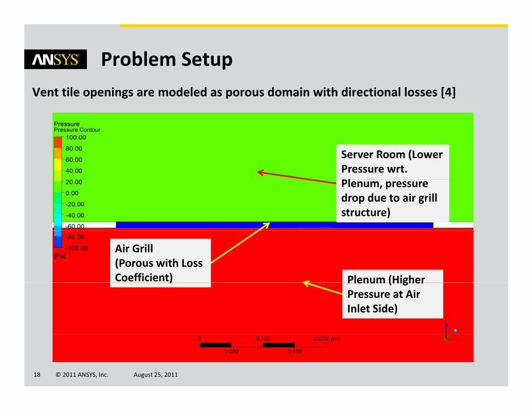
Problem SetupVent tile openings are modeled as porous domain with directional losses [4]
Server Room (Lower Pressure wrt. lPlenum, pressure
drop due to air grill structure)
Air Grill (Porous with Loss Coefficient) Plenum (Higher) Plenum (Higher
Pressure at Air Inlet Side)
© 2011 ANSYS, Inc. August 25, 201118
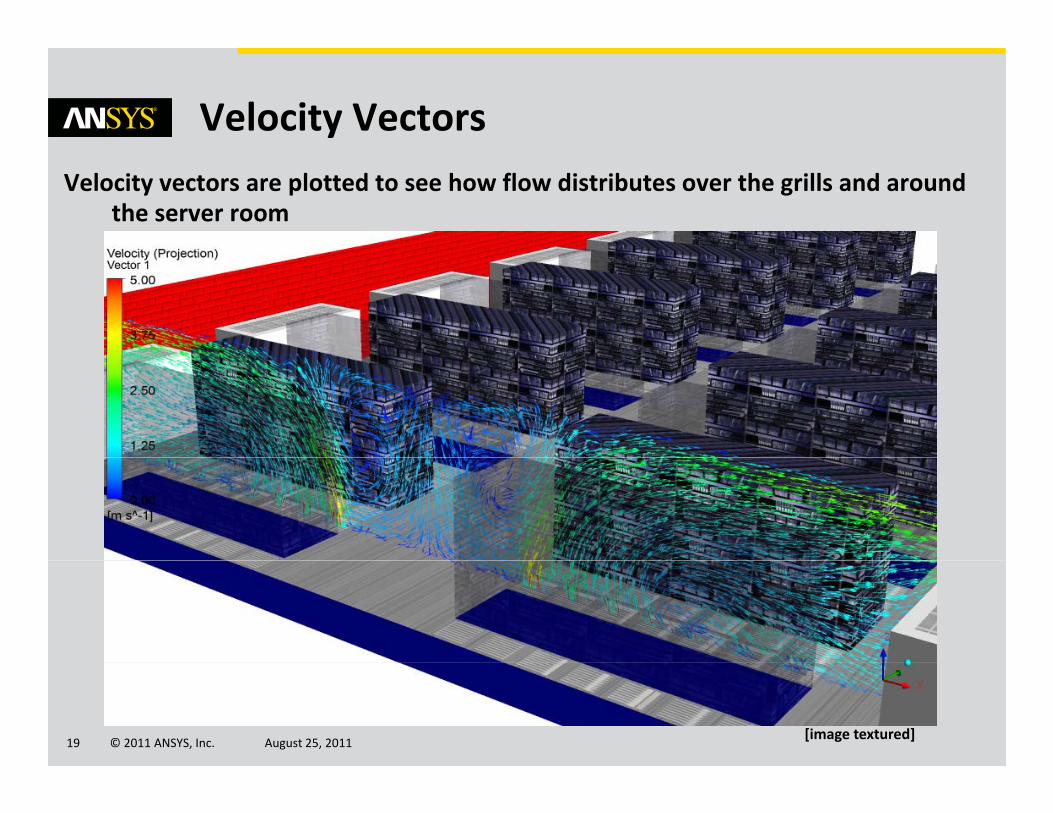
Velocity VectorsVelocity vectors are plotted to see how flow distributes over the grills and around
the server room
© 2011 ANSYS, Inc. August 25, 201119[image textured]
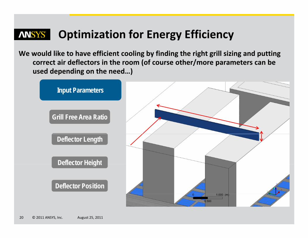
Optimization for Energy EfficiencyWe would like to have efficient cooling by finding the right grill sizing and putting
correct air deflectors in the room (of course other/more parameters can be used depending on the need…)p g )
Input Parameters
Grill Free Area Ratio
Deflector Length
Deflector HeightDeflector Height
Deflector Position
© 2011 ANSYS, Inc. August 25, 201120
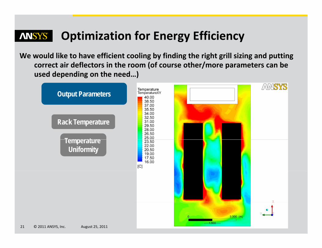
Optimization for Energy EfficiencyWe would like to have efficient cooling by finding the right grill sizing and putting
correct air deflectors in the room (of course other/more parameters can be used depending on the need…)p g )
Output Parameters
Rack Temperature
Temperature Temperature Uniformity
© 2011 ANSYS, Inc. August 25, 201121
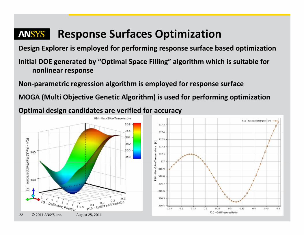
Response Surfaces OptimizationDesign Explorer is employed for performing response surface based optimization
Initial DOE generated by “Optimal Space Filling” algorithm which is suitable for nonlinear responsep
Non‐parametric regression algorithm is employed for response surface
MOGA (Multi Objective Genetic Algorithm) is used for performing optimization
Optimal design candidates are verified for accuracy
© 2011 ANSYS, Inc. August 25, 201122
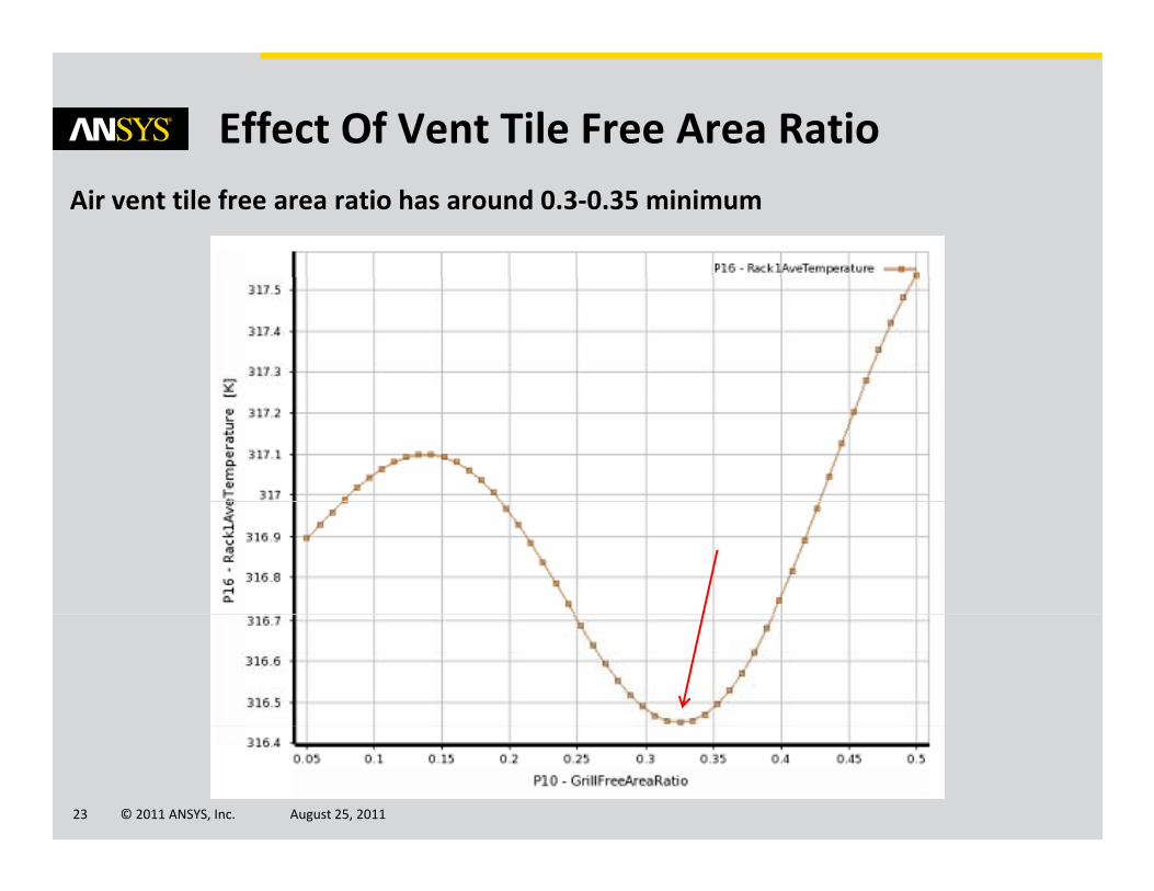
Effect Of Vent Tile Free Area RatioAir vent tile free area ratio has around 0.3‐0.35 minimum
© 2011 ANSYS, Inc. August 25, 201123
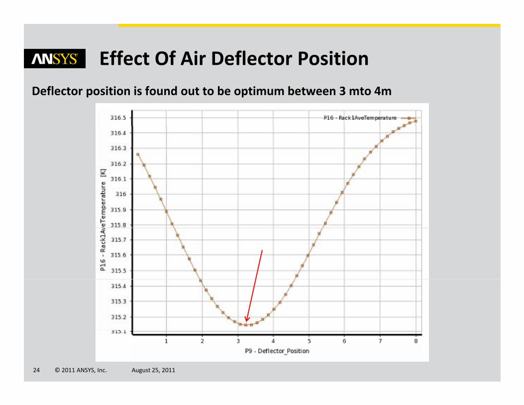
Effect Of Air Deflector PositionDeflector position is found out to be optimum between 3 mto 4m
© 2011 ANSYS, Inc. August 25, 201124
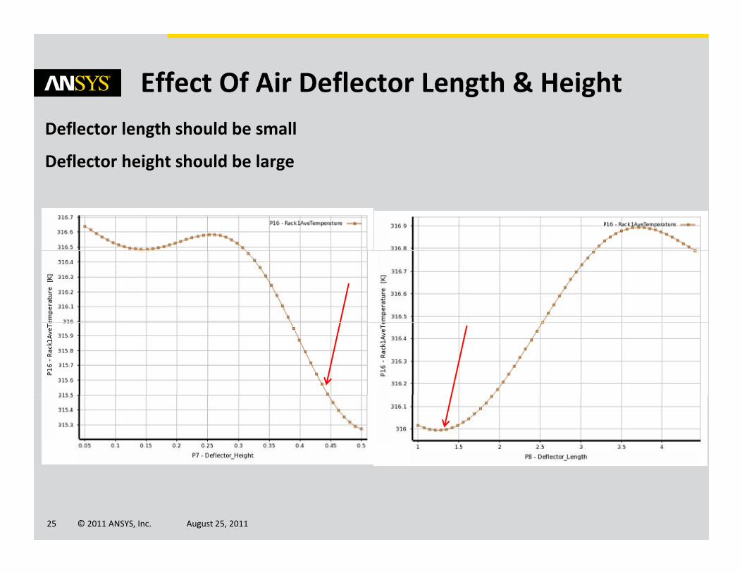
Effect Of Air Deflector Length & HeightDeflector length should be small
Deflector height should be large
© 2011 ANSYS, Inc. August 25, 201125
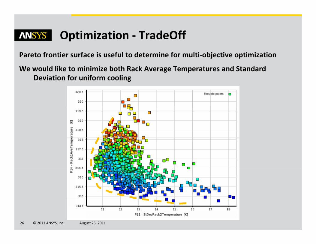
Optimization ‐ TradeOffPareto frontier surface is useful to determine for multi‐objective optimization
We would like to minimize both Rack Average Temperatures and Standard D i ti f if liDeviation for uniform cooling
© 2011 ANSYS, Inc. August 25, 201126
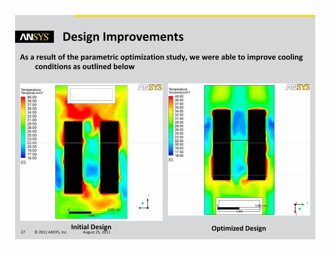
Design ImprovementsAs a result of the parametric optimization study, we were able to improve cooling
conditions as outlined below
© 2011 ANSYS, Inc. August 25, 201127Initial Design Optimized Design
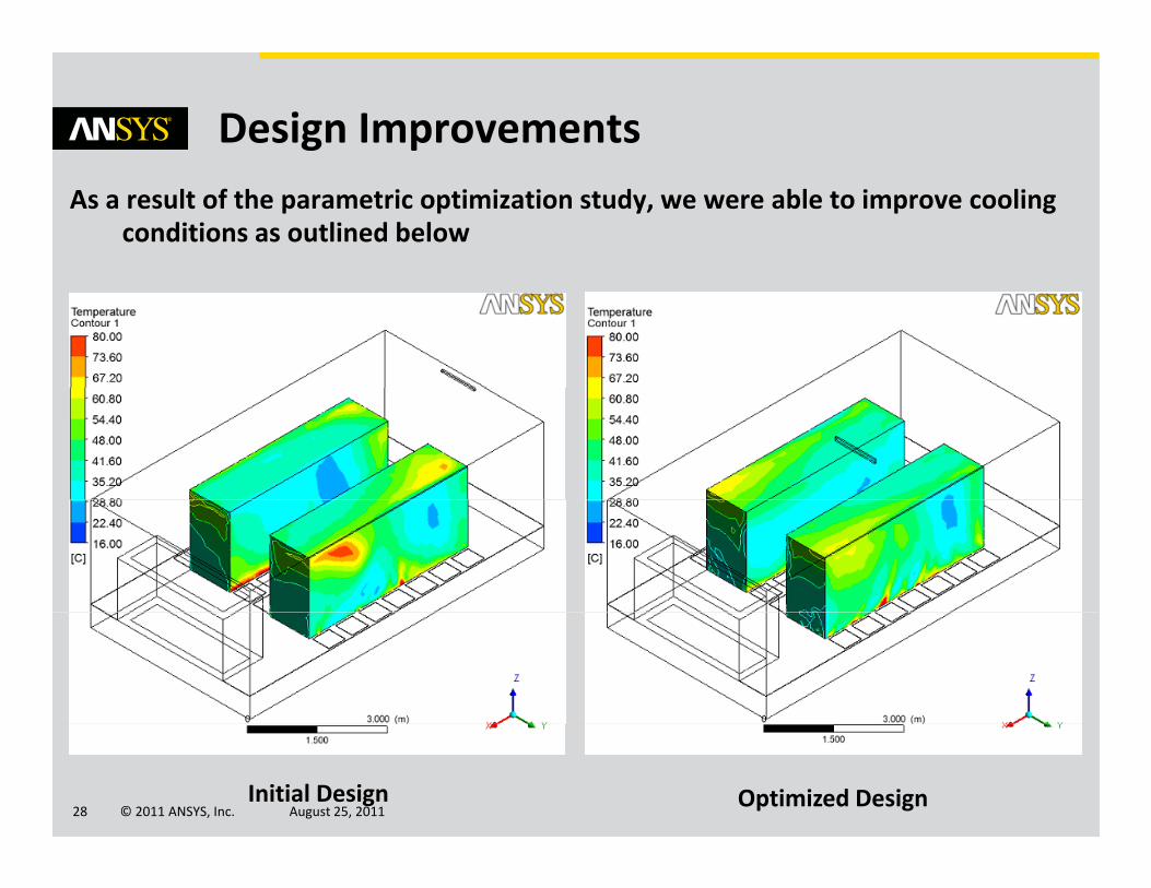
Design ImprovementsAs a result of the parametric optimization study, we were able to improve cooling
conditions as outlined below
© 2011 ANSYS, Inc. August 25, 201128Initial Design Optimized Design
ConclusionsAnsys CFX can be used to model thermal‐flow conditions of data centers
Ansys Design Explorer has robust tools to make parametric design space l ti d ti i ti b d lti l d lexploration and optimization based on multiple models
Data centers can be designed as energy efficient and kept as energy efficient using simulation technology as needs change
…
© 2011 ANSYS, Inc. August 25, 201129
References[1] U. Singh et.al. “CFD‐Based Operational Thermal Efficiency Improvement of a
Production Data Center”
[2] S V P t k “C t ti l M d li f Ai fl i R i d Fl D t C t ”[2] S.V. Patankar “Computational Modeling of Airflow in Raised‐Floor Data Centers”
[3] C.D. Patel et. al. “Thermal Consideration in Cooling Large Scale High Compute Density Data Centers”, EICTT Conference 2002 CA USA
[4] Handbook of Hydraulic Resistance 3rd Edition I. E. Idelchik, CRC Begell House –1994
[5]http://citeseerx ist psu edu/viewdoc/download?doi=10 1 1 9 5049&rep=rep1&t[5]http://citeseerx.ist.psu.edu/viewdoc/download?doi=10.1.1.9.5049&rep=rep1&type=pdf
© 2011 ANSYS, Inc. August 25, 201130

?QUESTIONS ?Thank you for your attention
Pl j i f H HPlease join us for Happy Hour following the conference.
© 2011 ANSYS, Inc. August 25, 201131
Ozen Engineering Inc: 1210 E. Arques Ave #207 • Sunnyvale, CA 94085 • (408) 732‐4665
Directions: Right on Tasman • Left on Lawrence • Left on Arques Ave.
Second Right into OEI parking lot.