Embed Size (px)
Citation preview
Efficient recovery of braking energy through a reversible dc substation
DANIEL CORNIC Senior R&D Engineer. Alstom Transport
Abstract
The full regeneration of the braking energy is one of the most promising sources of energy savings to transport sys-tem operators. This paper presents the outcome of a RailEnergy cooperative research program focusing on reduction of energy consumption in transport systems. Today, urban transportation systems are generally fed at 750 Vdc or 1,500Vdc via rectifier bridges and trains are equipped with modern 3-phase ac traction packages. This allow for easier and more effective implementation of dy-namic braking over a wider range of speed and voltage with the possibility of feeding back some of the energy via the 3rd rail or OCS to adjacent trains. The target of this project is to improve the line receptivity of dc power systems by transferring the excess energy to the ac side and thus regenerate it, via the transformer, to the ac medium voltage distribution network that is natu-rally receptive. This concept transforms the traditional unidirectional dc traction into a reversible one. It is suit-able to all known types of dc traction power supply systems from 600Vdc up to 3,000Vdc. The key benefits expected from reversible dc traction substations are: • Regeneration of 99% of the braking energy at all time, while maintaining priority to natural exchange of energy
between trains; this will allow eliminating the braking resistors, and thus reduce the train mass and heat release; • Regulation of its output voltage in traction and regeneration modes to reduce losses, and increase the pick-up of
energy from distant trains, and • Reducing the level of harmonics and improvement of the power factor on the ac side. Under an Alstom funded internal R&D programme two 750 Vdc prototypes dc reversible substations were built and tested on a dedicated tramway test-track at the Alstom plant in La Rochelle France. To reduce development time & costs the prototypes were built using state-of-the-art industrial variable speed drive converters, active harmonic filters, high power semiconductors modules, modern controls and protections, modular-ity, high integration while taking into account the specific requirements of the railway industry. The test results confirmed the theoretical findings and demonstrated that the reversible substations allowed regener-ating all of the excess available kinetic energy of the tramway.
Keywords: reversible; substation; regeneration, energy savings.
INTRODUCTION The 1997 UITP operator survey on metropolitan rail-ways energy consumption [1] established that some of the networks operating trains fitted with modern traction package enjoyed significant energy savings, up to 40% of the energy absorbed by the trains during the traction phase, through regeneration. In these rare cases the high line receptivity is essentially associated to the high train density and their high auxiliary consumptions. How-ever, most dc fed networks generally do not operate in such favourable conditions and excess braking energy cannot be regenerated back to the internal or external users and is generally dissipated into on-board braking resistors. This is an intrinsic feature of dc fed systems as they use diode rectifiers that only allow unidirectional flow of power, making it impossible to regenerate the
excess braking energy outside of the dc network. Throughout the years various attempts to reuse that ex-cess braking energy were investigated through wayside or on-board solutions energy storage systems. Use of inverters was also investigated to regenerate that excess energy to the ac networks. None of these solutions as-sociated with a diode rectifier substation yielded attrac-tive internal rate of returns (IRR) and never flooded the market. The increasing focus on energy savings and the reduc-tion of the carbon footprint led to the creation of RailEnergy [2], a UNIFE [3] R&D initiative funded by the European Commission. The following section gives a brief presentation of the RailEnergy mandate, its work-ing groups and the associated R&D programmes and finally the results and recommendations to be made to the UNIFE.
THE RAILENERGY R&D PROGRAMME As indicated on its website, RailEnergy is an Integrated Project co-funded by the European Commission under the 6th Framework Programme for Research and Devel-opment to reduce the energy consumption of railways. It is a four-year project and was initiated in September 2006. The concluding conference of the project took place last November 2010 in Brussels. The main objective of the project is to address energy efficiency of the integrated railway system and to inves-tigate and validate solutions ranging from the introduc-tion of innovative traction technologies, components and layouts to the development of rolling stock, operation and infrastructure management strategies. The overall project structure is presented in Appendix 1, Table 1 for information. The work presented in this paper was part of the SP3 Energy (NRG) Trackside work group led by RFI (Italian Rail Network operator). The following section details the roles and responsibilities of the SP3 subgroups
THE RAILENERGY PANEL 3 R&D PROGRAM: INNOVATIVE ENERGY EFFICIENT TRACKSIDE The 3 working sub-groups (see Table 1 in Appendix 1 covered the following activities • SP 3:1: Headed by NITEL, modelled the power dis-
tribution system
• SP 3.2: Headed by Alstom looked at improving ex-isting ac and dc power supply architecture. Four types of power supply were investigated:
1. Reversible dc substation (Alstom)
2. Real time energy management (Alstom)
3. 2x1.5 kV dc system (SNCF)
4. 2x25 kV asymmetrical ac system (Siemens)
• SP 3. 3: Headed by Siemens looked at the definition of new dc and ac power supply architectures.
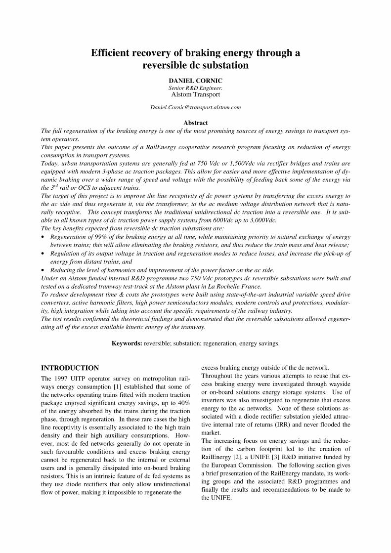
The simulation and evaluation of the most promising technologies were done following the process defined under SP2 (please refer to Appendix 1, table 1 and summarised in Figure 1hereafter.
Project target check
Cost benefit assessment
‘What if’scenario
Return on investment
Level 1:Demo scene performance
Level 2:SP
performance
Level 3SP / WP
performance
Ope
ratio
nal l
evel
Tech
nica
l le
vel
Railenergy sub-system interfaces WP 3.1 – 6.1
Railenergy global model WP 2.1
Trackside Components Traction Topologies
PI
Stra
tegi
c le
vel
Demo scene 1
Demo scene 2
Demo scene 3
KPI
Energy price Rail marketscenarios scenarios
ResultsSimulation / Calculation / Evaluation
Infrastructureselection
Rolling stock selection
Technology selection
Input
Operational evaluation
System validation
Strategic assessment
Economic evaluation
SP3-6 Evaluation
Operational WP 2.2profiles WP 2.3
WP 2.6
WP 2.5
Railenergy database wizard WP 2.4
Railenergy knowledge base WP 2.4
Scenario calculator WP 2.4:• Energy & CO2 savings• Energy & CO2 costs• LCC tool (MODTRAIN)
Commercial multi-train simulators:• Sidytrac (Siemens)• Elbas (Alstom)• ECOtranz (Bombardier)• Fabel (Enotrac)
Framework conditions
Figure 1: RailEnergy Evaluation Process
This paper reports on the activities of the SP3 NRG trackside workgroup and on the Harmonic and Energy Saving Optimiser (HESOP) an Alstom internal R&D project designed to validate the theoretical findings on a test track.
The following sections present the development work that enabled the successful completion of a fully inte-grated reversible dc substation for a 750 Vdc applica-tion.
SCOPE & OBJECTIVES OF THE REVERSIBLE DC SUBSTATION R&D PROGRAMME The scope of the programme included the assessment of potential solutions, the selection of the most promising one, the preparation of the associated design specifica-tions and the preparation of the associated testing and validation plan, the fabrication of the prototype and its test on a dedicated test track. The objectives of the programme were to validate the following: • Regenerate over 99% of the retrievable braking en-
ergy, • Confirm the feasibility of removing on-board brak-
ing resistors, • Demonstrate the feasibility of dynamic power bal-
ancing between adjacent substations to • Demonstrate the ability to compensate dynamically
fluctuations of the primary voltage, control over-loads, and avoid penalties on power contract sub-scription,
• Demonstrate the ability to achieve the total harmonic distortion (THD) as defined by the relevant standard,
• Demonstrate the ability to compensate the reactive power as per the local provider requirements,
METHODOLOGY The programme was implemented per the following methodology: • Identify the potential for energy recovery for subur-
ban and regional lines operating at line voltages of 1.5 kV and 3 kV,
• Design and build a power converter meeting the trac-tion and braking efficiency targets in the defined op-erating domains
• Design and build a reversible substation using the power converter identified above providing for ac-tive filtering, reactive power compensation, load bal-ancing between adjacent stations
• Validate the potential energy savings via simulations and testing
• Evaluate the LCC and the IRR of the proposed solu-tion.
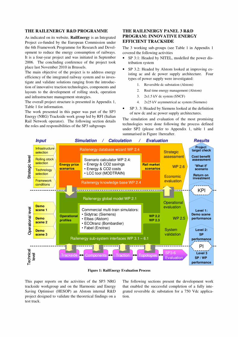
POTENTIAL FOR ENERGY RECOVERY ON SUBURBAN AND REGIONAL LINES For this study, applied to railway systems, suburban and regional lines were defined as lines with inter-station distances of 1.5 km and 4 km respectively under 1.5 kVdc and 3.0 kVdc. It also includes two theoretical high-speed lines with inter stations of 10 km and 30 km powered at 3 kV. The potential for energy regeneration is essentially based on the number of trains on the line, characterised by the headway, the installed power on each train and the speed of the trains when applying brakes, the fre-quency of braking and the auxiliary consumption. Power simulations using multi-train simulator running on typical operation as described above were run and plotted the traction power, the net braking power (ex-cluding energy exchanged between trains) per km of line as a function of headway. Figure 2 hereafter presents the result of these simula-tions.
Figure 2: Linear net Braking Power (absolute)
The simulation results indicate that for headway of 5 minutes or less inter-vehicle exchange was prevalent and most efficient. For headway greater than 5 minutes, regenerating back to the ac side become more efficient. This study also establishes that there is a potential for energy savings for suburban and regional railway sys-tems. While no simulations are shown here for urban systems application, similar type of curve were obtained.
CONVERTER MODEL The underlying requirements of the converter were de-fined through specific development tasks the end result of which was to establish the performance and definition of the prototype converter. Three areas were explored: • The rectifier and its operating domain in traction
mode
• The structure of the inverter and its efficiency,
• The operating domain of the inverter in braking mode.
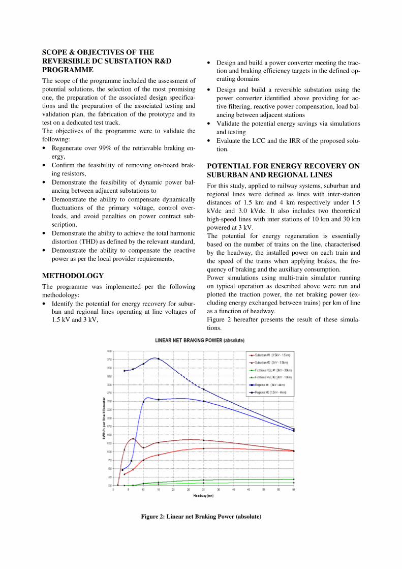
RECTIFIER DESIGN AND OPERATING DOMAIN (TRACTION MODE) The standard 750 Vdc diode bridge rectifier operating domain is defined by the diode characteristic in the (I, V) domain. Its characteristic is a constant negative slope between the no load voltage (around 800V) and the 3In voltage where at In is the current through the diode at 750V. This operating domain affects the ability to regenerate, taking into account fluctuations of pri-mary voltage as well as the legacy maximum bus-bar voltage of 900 Vdc, This translates into a maximum regeneration range of 70 V. To palliate this issue, the standard diode rectifier was replaced by a thyristor con-trolled one. This allows adjusting the rectifier input voltage independently of the load around the nominal voltage. Thus it increases the regeneration domain range from 70V to about 150 V. The resulting operating domain of the rectifier bridge is presented in Figure 3 hereafter.
Figure 3: Controlled Bridge Operating Domain
INVERTER EFFICIENCY TARGET One of the goals of the RailEnergy program was to im-prove the overall efficiency of converters to maximise the energy savings. Figure 4hereafter summarises the efficiency targets that were given to the designers of the inverter.
Figure 4: Inverter Efficiency Targets
INVERTER OPERATING DOMAIN (BRAKING MODE) As indicated earlier, the thyristor-controlled rectifier bridge allows maintaining substation output voltage at the nominal value, which increases the ability to regen-erate. As the line receptivity drops, the regeneration voltage increases. But if no loads are within the range of the regenerating train, this energy will be wasted. To increase the regeneration range allowing higher voltage is necessary. The increase of the maximum voltage was introduced through to a standard change in 2004. For all dc system, EN 50163:2004, has introduced a higher voltage in re-generation mode. For 750 Vdc, the maximum allowable is now 1,000 Vdc, thus allowing a 250V voltage drop to pick up regenerative energy from distant trains. Regenerating at higher voltage is also beneficial from a line losses point of view. Figure 5 presents the operating domain of the inverter of the reversible substation.
Figure 5: Operating Domain of the Inverter
The Converter also increases the power traction power capability maintaining a high current level all the way to the lowest voltage allowed. Finally the proposed converter will have several func-tions, all related to the program objectives, i.e., active filtering of the harmonics generated by the controlled rectifier bridge and by the load, power factor improve-ment and power load management.
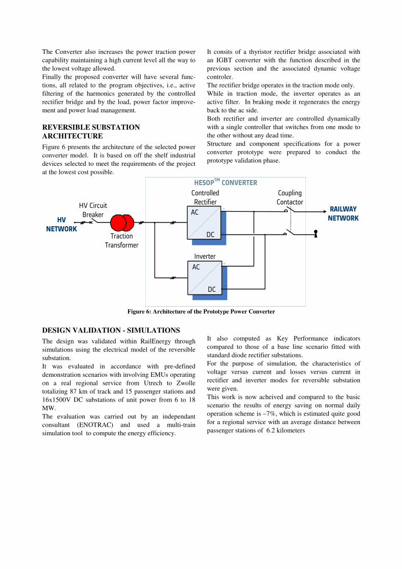
REVERSIBLE SUBSTATION ARCHITECTURE Figure 6 presents the architecture of the selected power converter model. It is based on off the shelf industrial devices selected to meet the requirements of the project at the lowest cost possible.
It consits of a thyristor rectifier bridge associated with an IGBT converter with the function described in the previous section and the associated dynamic voltage controler. The rectifier bridge operates in the traction mode only. While in traction mode, the inverter operates as an active filter. In braking mode it regenerates the energy back to the ac side. Both rectifier and inverter are controlled dynamically with a single controller that switches from one mode to the other without any dead time. Structure and component specifications for a power converter prototype were prepared to conduct the prototype validation phase.
��������
��������
�� ������
��������
����� ���� ����� ����
����������
� ��� �
�� � ���
� ��� �
����������� �����
��� �����
��������� ��
��
��
��
��
Figure 6: Architecture of the Prototype Power Converter
DESIGN VALIDATION - SIMULATIONS The design was validated within RailEnergy through simulations using the electrical model of the reversible substation. It was evaluated in accordance with pre-defined demonstration scenarios with involving EMUs operating on a real regional service from Utrech to Zwolle totalizing 87 km of track and 15 passenger stations and 16x1500V DC substations of unit power from 6 to 18 MW. The evaluation was carried out by an independant consultant (ENOTRAC) and used a multi-train simulation tool to compute the energy efficiency.
It also computed as Key Performance indicators compared to those of a base line scenario fitted with standard diode rectifier substations. For the purpose of simulation, the characteristics of voltage versus current and losses versus current in rectifier and inverter modes for reversible substation were given. This work is now acheived and compared to the basic scenario the results of energy saving on normal daily operation scheme is –7%, which is estimated quite good for a regional service with an average distance between passenger stations of 6.2 kilometers
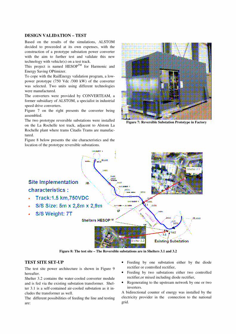
DESIGN VALIDATION – TEST Based on the results of the simulations, ALSTOM decided to proceeded at its own expenses, with the construction of a prototype substation power converter with the aim to further test and validate this new technology with vehicle(s) on a test track. This project is named HESOPTM for Harmonic and Energy Saving OPtimizer. To cope with the RailEnergy validation program, a low-power prototype (750 Vdc /300 kW) of the converter was selected. Two units using different technologies were manufactured. The converters were provided by CONVERTEAM, a former subsidiary of ALSTOM, a specialist in industrial speed drive converters. Figure 7 on the right presents the converter being assembled. The two prototype reversible substations were installed on the La Rochelle test track, adjacent to Alstom La Rochelle plant where trams Citadis Trams are manufac-tured. Figure 8 below presents the site characteristics and the location of the prototype reversible substations.
Figure 7: Reversible Substation Prototype in Factory
Figure 8: The test site – The Reversible substations are in Shelters 3.1 and 3.2
TEST SITE SET-UP The test site power architecture is shown in Figure 9 hereafter. Shelter 3.2 contains the water-cooled converter module and is fed via the existing substation transformer. Shel-ter 3.1 is a self-contained air-cooled substation as it in-cludes the transformer as well. The different possibilities of feeding the line and testing are:
• Feeding by one substation either by the diode
rectifier or controlled rectifier, • Feeding by two substations either two controlled
rectifier,or mixed including diode rectifier, • Regenerating to the upstream network by one or two
inverters. A bidirectional counter of energy was installed by the electricity provider in the connection to the national grid.
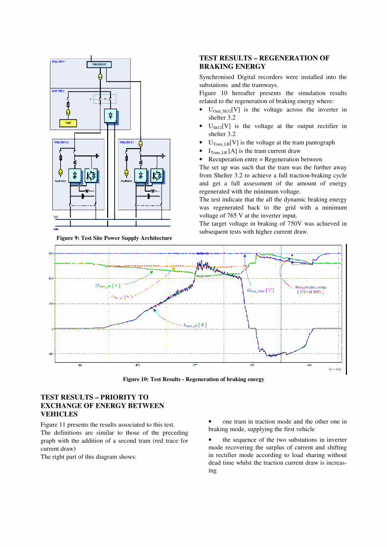
Figure 9: Test Site Power Supply Architecture
TEST RESULTS – REGENERATION OF BRAKING ENERGY Synchronised Digital recorders were installed into the substations and the tramways. Figure 10 hereafter presents the simulation results related to the regeneration of braking energy where: • UOnd_Sh32[V] is the voltage across the inverter in
shelter 3.2 • USh32[V] is the voltage at the output rectifier in
shelter 3.2 • UTram_LR[V] is the voltage at the tram pantograph • ITram_LR [A] is the tram current draw • Recuperation entre = Regeneration between The set up was such that the tram was the further away from Shelter 3.2 to achieve a full traction-braking cycle and get a full assessment of the amount of energy regenerated with the minimum voltage. The test indicate that the all the dynamic braking energy was regenerated back to the grid with a minimum voltage of 765 V at the inverter input. The target voltage in braking of 750V was achieved in subsequent tests with higher current draw.
Figure 10: Test Results - Regeneration of braking energy
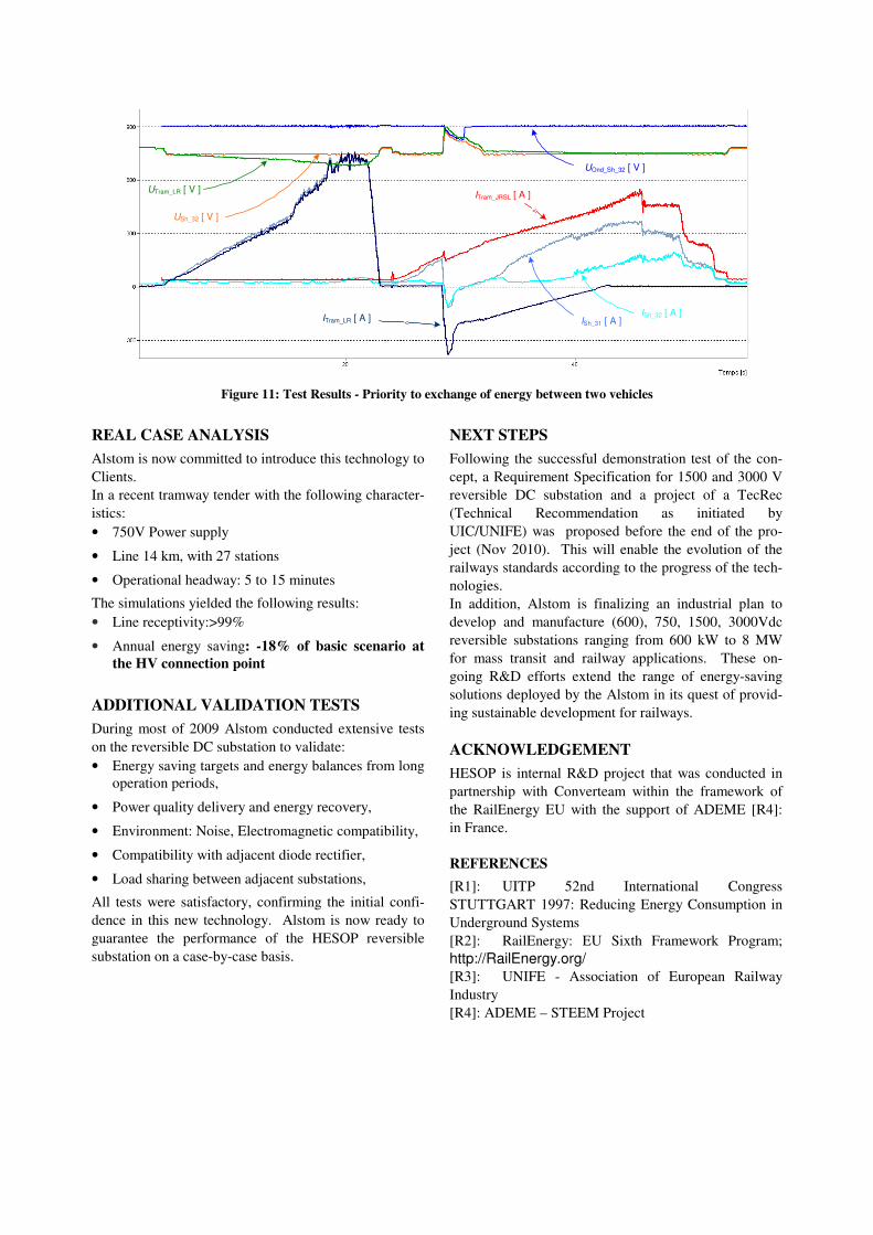
TEST RESULTS – PRIORITY TO EXCHANGE OF ENERGY BETWEEN VEHICLES Figure 11 presents the results associated to this test. The definitions are similar to those of the preceding graph with the addition of a second tram (red trace for current draw) The right part of this diagram shows:
• one tram in traction mode and the other one in braking mode, supplying the first vehicle
• the sequence of the two substations in inverter mode recovering the surplus of current and shifting in rectifier mode according to load sharing without dead time whilst the traction current draw is increas-ing
<
ITram_JRSL [ A ]
ISh_31 [ A ]ISh_32 [ A ]ITram_LR [ A ] <
UTram_LR [ V ]
USh_32 [ V ]
UOnd_Sh_32 [ V ]
Figure 11: Test Results - Priority to exchange of energy between two vehicles
REAL CASE ANALYSIS Alstom is now committed to introduce this technology to Clients. In a recent tramway tender with the following character-istics: • 750V Power supply
• Line 14 km, with 27 stations
• Operational headway: 5 to 15 minutes
The simulations yielded the following results: • Line receptivity:>99%
• Annual energy saving: -18% of basic scenario at the HV connection point
ADDITIONAL VALIDATION TESTS During most of 2009 Alstom conducted extensive tests on the reversible DC substation to validate: • Energy saving targets and energy balances from long
operation periods,
• Power quality delivery and energy recovery,
• Environment: Noise, Electromagnetic compatibility,
• Compatibility with adjacent diode rectifier,
• Load sharing between adjacent substations,
All tests were satisfactory, confirming the initial confi-dence in this new technology. Alstom is now ready to guarantee the performance of the HESOP reversible substation on a case-by-case basis.
NEXT STEPS Following the successful demonstration test of the con-cept, a Requirement Specification for 1500 and 3000 V reversible DC substation and a project of a TecRec (Technical Recommendation as initiated by UIC/UNIFE) was proposed before the end of the pro-ject (Nov 2010). This will enable the evolution of the railways standards according to the progress of the tech-nologies. In addition, Alstom is finalizing an industrial plan to develop and manufacture (600), 750, 1500, 3000Vdc reversible substations ranging from 600 kW to 8 MW for mass transit and railway applications. These on-going R&D efforts extend the range of energy-saving solutions deployed by the Alstom in its quest of provid-ing sustainable development for railways.
ACKNOWLEDGEMENT HESOP is internal R&D project that was conducted in partnership with Converteam within the framework of the RailEnergy EU with the support of ADEME [R4]: in France.
REFERENCES [R1]: UITP 52nd International Congress STUTTGART 1997: Reducing Energy Consumption in Underground Systems [R2]: RailEnergy: EU Sixth Framework Program; http://RailEnergy.org/ [R3]: UNIFE - Association of European Railway Industry [R4]: ADEME – STEEM Project
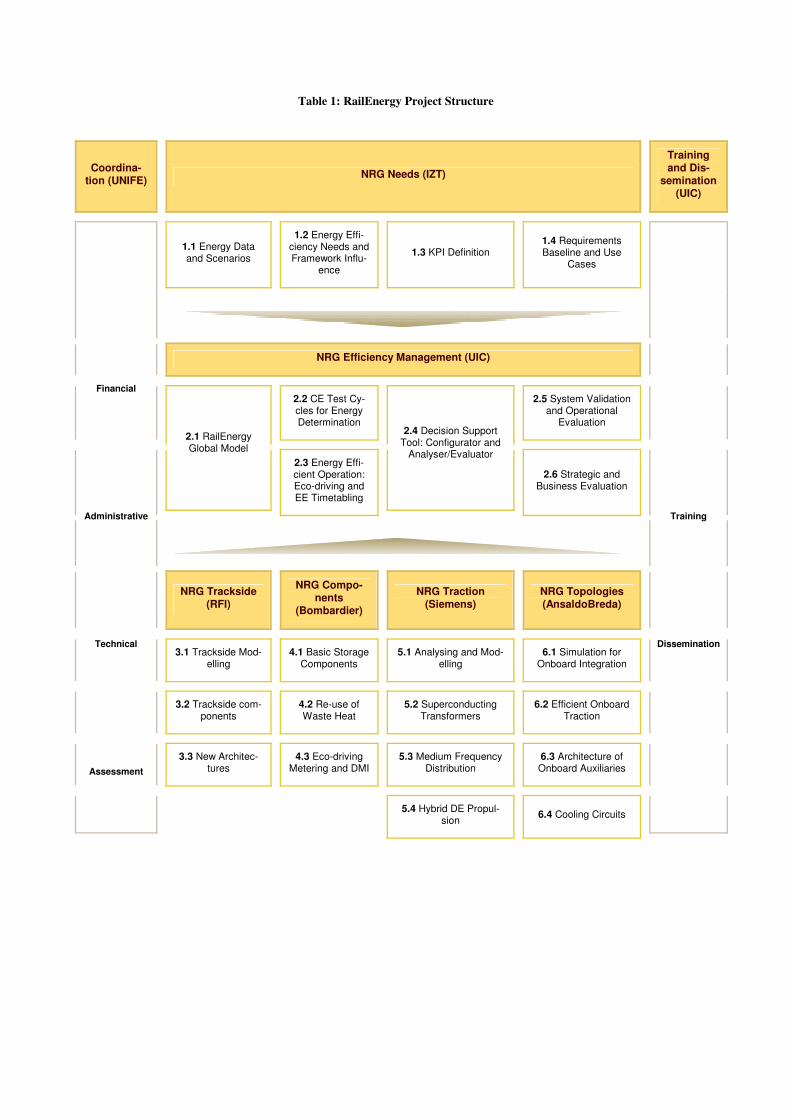
Table 1: RailEnergy Project Structure
Coordina-tion (UNIFE) NRG Needs (IZT)
Training and Dis-
semination (UIC)
1.1 Energy Data and Scenarios
1.2 Energy Effi-ciency Needs and Framework Influ-
ence
1.3 KPI Definition 1.4 Requirements Baseline and Use
Cases
�
NRG Efficiency Management (UIC)
2.2 CE Test Cy-cles for Energy Determination
2.5 System Validation and Operational
Evaluation 2.1 RailEnergy Global Model
2.3 Energy Effi-cient Operation: Eco-driving and EE Timetabling
2.4 Decision Support Tool: Configurator and
Analyser/Evaluator
2.6 Strategic and Business Evaluation
�
NRG Trackside (RFI)
NRG Compo-nents
(Bombardier)
NRG Traction (Siemens)
NRG Topologies (AnsaldoBreda)
3.1 Trackside Mod-elling
4.1 Basic Storage Components
5.1 Analysing and Mod-elling
6.1 Simulation for Onboard Integration
3.2 Trackside com-ponents
4.2 Re-use of Waste Heat
5.2 Superconducting Transformers
6.2 Efficient Onboard Traction
3.3 New Architec-tures
4.3 Eco-driving Metering and DMI
5.3 Medium Frequency Distribution
6.3 Architecture of Onboard Auxiliaries
Financial
Administrative
Technical
Assessment
� � 5.4 Hybrid DE Propul-sion 6.4 Cooling Circuits
Training
Dissemination


![Experimental Realization of Josephson Junctions for an ... · PDF filedemonstrated in the laboratory with super uid helium SQUIDs [4{6]. The atom SQUID is particularly attrac-](https://img.pdfslide.net/doc/110x75/5aaa21567f8b9a7c188db97b/experimental-realization-of-josephson-junctions-for-an-in-the-laboratory-with.jpg)