Embed Size (px)
Citation preview
1
Efficient Ventilation Solution for Critical Engine RoomA Vertiv™ Case Study
About The Company
A leading global engineering firm, renowned for its ‘concept to commissioning’ project solutions, and for specialization in infrastructure development in power, oil and gas, water, telecommunications, mining, data centers, smart cities and finance markets. It has more than 100 offices worldwide and executed projects in more than 100 countries in six continents.
With backing of solid experience in construction and engineering, this business giant has helped in constructing India’s first East Coast based Liquefied Natural Gas (LNG) terminal.
This East Coast based LNG terminal is one of its kind that intents to support the growing needs of natural gas in different regions of the nation.
Background
Natural gas is one of the most significant life force in fast growing economy like India, which helps in meeting country's total energy requirement. With a growing demand of 8% per annum, import of natural gas in liquid form has been encouraged from 2003. Now imported LNG constitutes ≈25% of country’s annual natural gas consumption.
This megastructure is basically a storage facility for LNG that comprises special tanks and re-gasification engine room supported by captive power plant building where Vertiv has been engaged in providing thermal and power management solutions with chilled water unit and through UPS & batteries respectively. In continuation, contractor has asked Vertiv to provide a pressurized ventilation solution in engine room. The engines generate large amount of heat which not only affects engine combustion cycle adversely but also damages other equipment such as generators, cooling and electrical systems, hence customer was in need of an extravagant solution that can improve the airflow convection property in the engine rooms.
Case SummaryLocation: South India
Critical Needs:
y To create a pressurized system in the engine room with an allowable temperature rise of 5 °C.
y Maintain optimum air flow within engine room considering 30 air change per hour as per design data.
y 24x7 operations.
y Rapid deployment of necessary solution.
Vertiv Solutions:
y Design, supply, installation & commissioning of the Engine room pressurization system comprising 6Nos. of 23 m3/s fan on East Side and 3Nos. of 16m3/s fan on West Side.
y Air distribution system with accessories such as pressure relief damper.
Result
y Optimum ventilation enables engines to achieve a proper combustion cycle, improves engine life and facilitates easy maintenance.
y End-to-end rapidly deployed thermal management solution from Vertiv enables customer to meet projected time line.
2
A Vertiv™ Case Study
Site Challenges
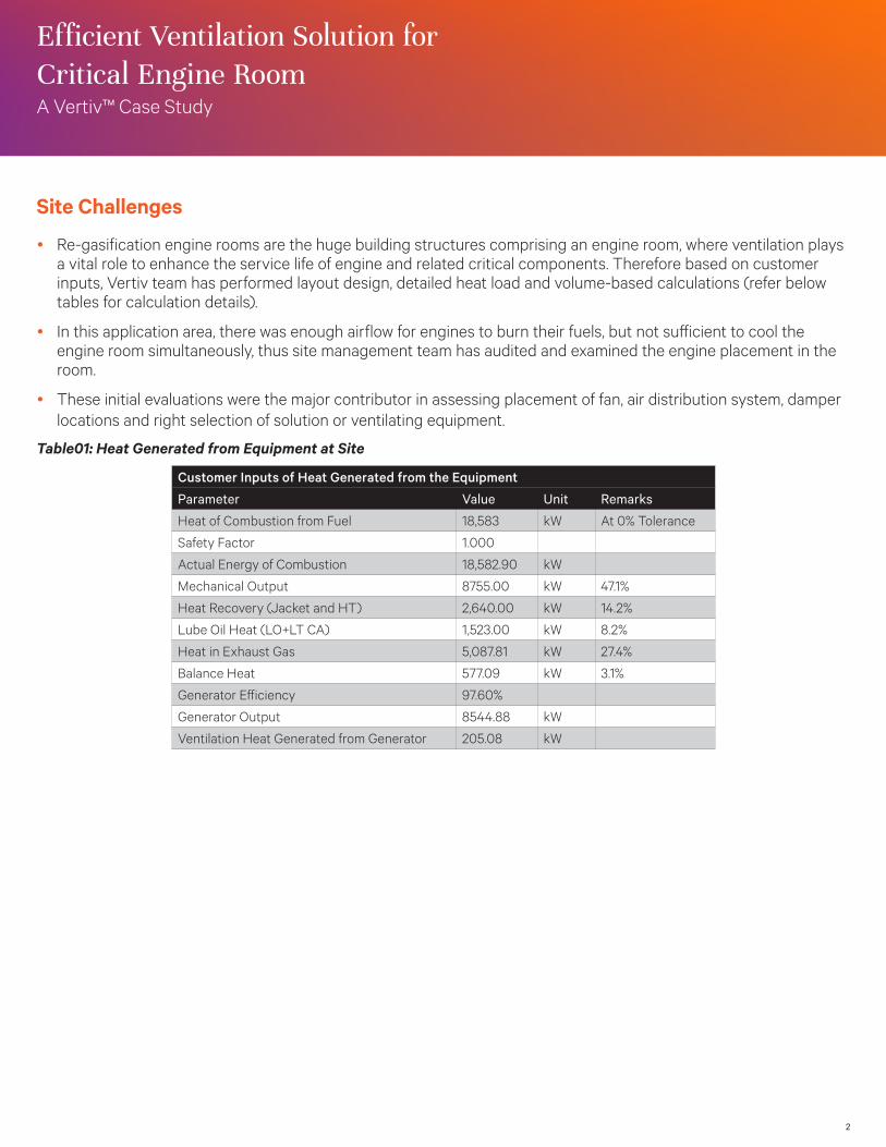
y Re-gasification engine rooms are the huge building structures comprising an engine room, where ventilation plays a vital role to enhance the service life of engine and related critical components. Therefore based on customer inputs, Vertiv team has performed layout design, detailed heat load and volume-based calculations (refer below tables for calculation details).
y In this application area, there was enough airflow for engines to burn their fuels, but not sufficient to cool the engine room simultaneously, thus site management team has audited and examined the engine placement in the room.
y These initial evaluations were the major contributor in assessing placement of fan, air distribution system, damper locations and right selection of solution or ventilating equipment.
Table01: Heat Generated from Equipment at Site
Customer Inputs of Heat Generated from the Equipment
Parameter Value Unit Remarks
Heat of Combustion from Fuel 18,583 kW At 0% Tolerance
Safety Factor 1.000
Actual Energy of Combustion 18,582.90 kW
Mechanical Output 8755.00 kW 47.1%
Heat Recovery (Jacket and HT) 2,640.00 kW 14.2%
Lube Oil Heat (LO+LT CA) 1,523.00 kW 8.2%
Heat in Exhaust Gas 5,087.81 kW 27.4%
Balance Heat 577.09 kW 3.1%
Generator Efficiency 97.60%
Generator Output 8544.88 kW
Ventilation Heat Generated from Generator 205.08 kW
Efficient Ventilation Solution for Critical Engine Room
3
Solution Overview
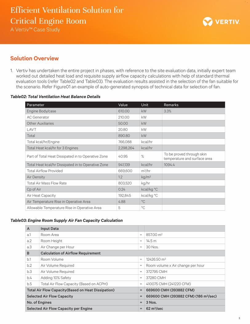
1. Vertiv has undertaken the entire project in phases, with reference to the site evaluation data, initially expert team worked out detailed heat load and requisite supply airflow capacity calculations with help of standard thermal evaluation tools (refer Table02 and Table03). The evaluation results assisted in the selection of the fan suitable for the scenario. Refer Figure01 an example of auto-generated synopsis of technical data for selection of fan.
Table02: Total Ventilation Heat Balance Details
Parameter Value Unit Remarks
Engine Body/case 610.00 kW 3.3%
AC Generator 210.00 kW
Other Auxiliaries 50.00 kW
LAVT 20.80 kW
Total 890.80 kW
Total kcal/hr/Engine 766,088 kcal/hr
Total Heat kcal/hr for 3 Engines 2,298,264 kcal/hr
Part of Total Heat Dissipated in to Operative Zone 40.95 % To be proved through skin temperature and surface area
Total Heat kcal/hr Dissipated in to Operative Zone 941,139 kcal/hr 1094.4
Total Airflow Provided 669,600 m3/hr
Air Density 1.2 kg/m3
Total Air Mass Flow Rate 803,520 kg/hr
Cp of Air 0.24 kcal/kg °C
Air Heat Capacity 192,845 kcal/kg °C
Air Temperature Rise in Operative Area 4.88 °C
Allowable Temperature Rise in Operative Area 5 °C
Table03: Engine Room Supply Air Fan Capacity Calculation
A Input Data
a.1 Room Area = 857.00 m2
a.2 Room Height = 14.5 m
a.3 Air Change per Hour = 30 Nos.
B Calculation of Airflow Requirement
b.1 Room Volume = 12426.50 m3
b.2 Air Volume Required = Room volume x Air change per hour
b.3 Air Volume Required = 372795 CMH
b.4 Adding 10% Safety = 37280 CMH
b.5 Total Air Flow Capacity (Based on ACPH) = 410075 CMH (241220 CFM)
Total Air Flow Capacity(Based on Heat Dissipation) = 669600 CMH (393882 CFM)
Selected Air Flow Capacity = 669600 CMH (393882 CFM) (186 m3/sec)
No. of Engines = 3 Nos.
Selected Air Flow Capacity per Engine = 62 m3/sec
A Vertiv™ Case Study
Efficient Ventilation Solution for Critical Engine Room
4
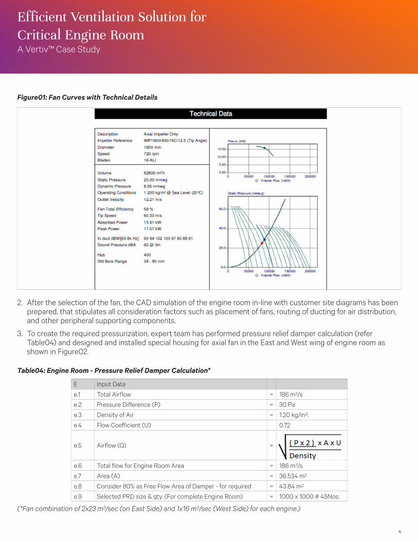
Figure01: Fan Curves with Technical Details
2. After the selection of the fan, the CAD simulation of the engine room in-line with customer site diagrams has beenprepared, that stipulates all consideration factors such as placement of fans, routing of ducting for air distribution,and other peripheral supporting components.
3. To create the required pressurization, expert team has performed pressure relief damper calculation (referTable04) and designed and installed special housing for axial fan in the East and West wing of engine room asshown in Figure02.
Table04: Engine Room - Pressure Relief Damper Calculation*
E Input Data
e.1 Total Airflow = 186 m3/s
e.2 Pressure Difference (P) = 30 Pa
e.3 Density of Air = 1.20 kg/m3.
e.4 Flow Coefficient (U) 0.72
e.5 Airflow (Q) =
e.6 Total flow for Engine Room Area = 186 m3/s
e.7 Area (A) = 36.534 m2
e.8 Consider 80% as Free Flow Area of Damper - for required = 43.84 m2
e.9 Selected PRD size & qty. (For complete Engine Room) = 1000 x 1000 # 45Nos.
(*Fan combination of 2x23 m3/sec (on East Side) and 1x16 m3/sec (West Side) for each engine.)
A Vertiv™ Case Study
Efficient Ventilation Solution for Critical Engine Room
5
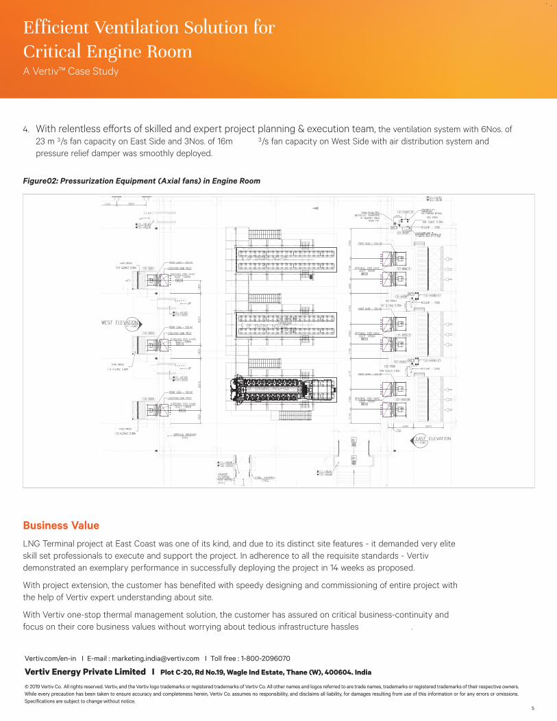
4. the ventilation system with 6Nos. of 23 m 3/s fan capacity on East Side and 3Nos. of 16m 3/s fan capacity on West Side with air distribution system and pressure relief damper was smoothly deployed.
Figure02: Pressurization Equipment (Axial fans) in Engine Room
Business ValueLNG Terminal project at East Coast was one of its kind, and due to its distinct site features - it demanded very elite skill set professionals to execute and support the project. In adherence to all the requisite standards - Vertiv demonstrated an exemplary performance in successfully deploying the project in 14 weeks as proposed.
With project extension, the customer has benefited with speedy designing and commissioning of entire project with the help of Vertiv expert understanding about site.
With Vertiv one-stop thermal management solution, the customer has assured on critical business-continuity and focus on their core business values without worrying about tedious infrastructure hassles .
A Vertiv™ Case Study
Critical Engine Room
Vertiv.com/en-in I E-mail : [email protected] I Toll free : 1-800-2096070
Vertiv Energy Private Limited I Plot C-20, Rd No.19, Wagle Ind Estate, Thane (W), 400604. India
© 2019 Vertiv Co. All rights reserved. Vertiv, and the Vertiv logo trademarks or registered trademarks of Vertiv Co. All other names and logos referred to are trade names, trademarks or registered trademarks of their respective owners. While every precaution has been taken to ensure accuracy and completeness herein, Vertiv Co. assumes no responsibility, and disclaims all liability, for damages resulting from use of this information or for any errors or omissions. Specifications are subject to change without notice.