Embed Size (px)
Citation preview

Bristol Water’s Frome WTW is located 20 miles south east of Bristol and supplies a population of 12,000 people. The works is supplied with 5Ml/d of raw water from Egford wells and provides membrane treatment followed by chlorination before storage in two on-site service reservoirs. The service reservoirs are also supplied with up
to 13Ml/d of treated water pumped from Oldford WTW. Nitrate levels from the Egford wells exceeded the prescribed concentration value (PCV) of 50mg/l and caused the works to be removed from service for periods in 2007 and 2008. To treat high nitrates in the water from Egford wells, Bristol Water agreed an undertaking with the Drinking Water Inspectorate (DWI) to provide an Egford Nitrate Reduction Scheme (NRS). This is a blending solution with treated water from Oldford WTW being blended with Egford wells water. This paper discusses the many complexities encountered over the project duration and outlines how these were overcome in a sustainable way.
Blending solutionThe blending solution was achieved by a new low lift pumping station, actuated valves interconnecting pipework and a static mixer. The blending system operates automatically based on nitrate meter readings. A process analysis was undertaken to confirm that a 1:1 to blend ratio would achieve average nitrate levels compliant with the DWI requirements.
During a high nitrate event at Egford, the blending solution relies on a supply from Oldford WTW to produce a nitrate compliant blend. To mitigate against the risk of losing the pumped supply from Oldford part of the existing service reservoir volume at Egford was dedicated as a standby volume of Oldford.
Resilience for a 12-hour failure of Oldford WTW was achieved by dedicating a 2.5Ml standby volume at Frome Reservoir 1A and 1B (combined total volume of 4.5Ml). This volume, based on Egford
www.WaterProjectsOnline.com Water Treatment & Supply
Page 1 of 4 UK Water Projects 2015
Egford Nitrate Reduction Schemetackling a nitrate problem using existing assets whilst maintaining
operation of a town’s water treatment works and resilience of supplyby Agata Crussell MEng MSc CEng MICE
Pump room - Courtesy of Black & Veatch
input being 5Ml/d and therefore requiring 2.5Ml of Oldford WTW water for 12 hours blending, is kept turned over by operating the reservoirs as normal but never allowing volume in the combined reservoir to fall below 56%.
The loss of 2.5Ml of storage at Frome WTW was compensated for by including 2.5Ml of additional storage at Millmarsh. This was a service reservoir growth scheme located some 6 miles from Frome. The Millmarsh reservoir itself cannot be used as blending storage since on occasions the nitrate concentration in Millmarsh can be too high to provide sufficient dilution.
The control of the blending system is done by using new electrically operated valves for operating two systems, normal and blending, when nitrate levels are high. In order to assess the transient implications of the proposed blending pumping station and modifications to the South East Trunk Mains Network, a surge

www.WaterProjectsOnline.com Water Treatment & Supply
Page 2 of 4 UK Water Projects 2015
analysis was carried out to confirm there was no potential for adverse surge conditions associated with the modifications.
Site constraints and enabling worksThe site constraints and lack of space within the existing treatment works site dictated the general arrangement. The footprint of the pumping station was kept to a minimum with the overarching priority of minimizing the impact on the existing structures and pipework as the existing plant needed to be kept operational.
The pumping station is adjacent to a Victorian brick reservoir (Reservoir 1). To enable construction of the new PS, the incoming 18” main and 12” inlet to Reservoir 1 (pipework at 3.5m depth) had to be diverted.
The uncertainty of exact locations of existing infrastructure in relation to the proposed pumping station and external pipework was identified as the biggest risk on the project. There were discrepancies between site record drawings, Bristol Water’s GIS data and topographical survey results.
Non-intrusive survey options were researched and enquiries made with suppliers to try to obtain more certainty. However, due to the depth of existing services, the accuracy expected was too low (+/- 400mm) for detailed design. A detailed manhole survey to verify the depth and alignment of each pipe gave better results.
Pumping stationExcavation for the pumping station structure was undertaken within a sheet pile coffer dam due to limited space on site. Due to two hard limestone layers in the clay found on site, pre-augering was required to assist in inserting temporary piles to their required depth and minimise vibration to the adjacent reservoir and noise disruption to nearby residents.
The pumping station consists of two separate rooms for health and safety purposes. The MCC room is located at the ground level and accessible from the hardstanding. The pump room is within a 4.4m deep basement accessible from the hardstanding via a single door and a three-flight access staircase.
To facilitate removal of plant through roof access covers, the building for the MCC room and access staircase were offset from the pump room chamber. The pumps are removed from the pump room basement via roof access hatches positioned above them and lifted using a davit with lifting chain block and HIAB crane from the hardstanding. Valves and ancillary equipment are lifted using a portable lifting davit and lowered onto a trolley. There is a dedicated access hatch for their removal from the pump room. The access hatches are complete with fall protection grids.
Pump selectionTwo sets of duty/standby pumps at 5.5Ml/d at 10m head duty were required for the Egford nitrate blending pumping station. The initial scope for the structure was to have a building with pumps at ground level and pipework in trenches. Due to hydraulic restrictions of very low discharge head and high flows, the choice of suitable pumps capable of pumping efficiently was limited.
Four types of pump were considered for use:
• Borehole pumps. • Vertical turbine pumps. • End suction pumps. • Drywell submersible pumps.
Each of these could provide positive suction lift without the risk of air entrapment while pumping at low heads within the system. The pumps were compared based on maintenance, energy usage, access, lifting and construction.
Site constraints: construction of PS in close proximity to existing plantCourtesy of Black & Veatch
Excavation within sheet pile coffer dam - Courtesy of Black & Veatch
Pre-augering for sheet pile coffer dam installationCourtesy of Black & Veatch

www.WaterProjectsOnline.com Water Treatment & Supply
Page 3 of 4 UK Water Projects 2015
The borehole pump was ruled out by Bristol Water due to low efficiency for this application and high power use. The vertical turbine pump was also ruled out based on high cost and the need for a larger building requiring a change to the planning application.
End suction pump and drywell submersible pump were therefore selected as favourable options. The end suction pump is widely used in a potable water systems but requires a deeper chamber and a larger footprint. The drywell submersible pump is predominantly used in dirty water systems; however the application of DWI approved materials allows for potable water use.
The most suitable pump available was a submersible pump. The drywell installation was preferred for water quality reasons and to allow for access and maintenance to the pumps and valves.
Although the pump selected is capable of pumping the required range of flows at the various static heads within the system characteristics, the pump’s overall efficiency is poor. The expected efficiency was between 38% and 74%.
The last incident of high nitrate levels occurred early 2008. The blending facility is required by DWI, and the pumps will be operational when the nitrate levels are high. To keep the system sweet, the pumps will run for 1 hour per day, which equates to only 4% of the time. The efficiency of the pumps is unlikely to have significant effect on overall operational costs and BW approved these pumps based on cost and low frequency of use.
Ventilation A noise survey was undertaken to identify noise sources and the likely noise levels in operation. To mitigate the risk of complaints from local residents the sound power level of the pumps and ventilations equipment (fan/louvers) was specified so as not to exceed 53dBA.
Two options for ventilation of the pump room were considered at the early stage of design to allow adequate space for the required ventilation and noise attenuation equipment.
• Option1: Air is taken in and out through louvers 1m above the ground level pump room walls. The air is supplied to pump room through ducts and fan at lower level.
• Option 2: Air is taken in and out of the pump room via louvered penthouses mounted on the roof slab at ground level. The air is supplied to pump room through ducts and fan at lower level.
Option 2 was chosen by Bristol Water for aesthetic aspects. The roof would be at ground level and so there was no need for handrailing around it and stepped access (requirements for option 1), which posed additional challenges for lifting of the equipment using HIAB crane. The pump room vents are ducted down to low level fans within the basement area ensuring an adequate flow path to provide air flow over the pumps and allowing easy access and maintenance to be carried out on the fans without the requirement for any temporary scaffolding.
Reservoir compartment interconnection Reservoirs 3A & 3B at Frome WTW were arranged in series, such that the treated water from Egford could only pass into 3B, before being passed on. A new connection from the inlet to 3B into 3A was made allowing greater functionality and independent maintenance of the reservoirs. The reservoir is the only source of water to a population of 12,000 people, so an effective engineering solution was required to minimise disruption of supply.
The design of the new connection for a 300mm diameter high level bellmouth inlet for Egford water into reservoir 3A through the internal compartment wall used an innovative method. A stainless
18” CI main diversion under critical CAP zone supply main - Courtesy of Black & Veatch
www.WaterProjectsOnline.com Water Treatment & Supply
Page 4 of 4 UK Water Projects 2015
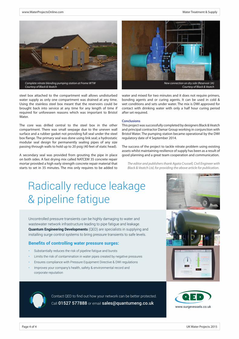
New connection on dry side (Reservoir 3A) Courtesy of Black & Veatch
Complete nitrate blending pumping station at Frome WTWCourtesy of Black & Veatch
steel box attached to the compartment wall allows undisturbed water supply as only one compartment was drained at any time. Using the stainless steel box meant that the reservoirs could be brought back into service at any time for any length of time if required for unforeseen reasons which was important to Bristol Water.
The core was drilled central to the steel box in the other compartment. There was small seepage due to the uneven wall surface and a rubber gasket not providing full seal under the steel box flange. The primary seal was done using link seal; a hydrostatic modular seal design for permanently sealing pipes of any size passing through walls to hold up to 20 psig (40 feet of static head).
A secondary seal was provided from grouting the pipe in place on both sides. A fast drying mix called NATCEM 35 concrete repair mortar provided a high early strength concrete repair material that starts to set in 35 minutes. The mix only requires to be added to
water and mixed for two minutes and it does not require primers, bonding agents and or curing agents. It can be used in cold & wet conditions and sets under water. The mix is DWI approved for contact with drinking water with only a half hour curing period after set required.
ConclusionsThis project was successfully completed by designers Black & Veatch and principal contractor Damar Group working in conjunction with Bristol Water. The pumping station became operational by the DWI regulatory date of 4 September 2014.
The success of the project to tackle nitrate problem using existing assets whilst maintaining resilience of supply has been as a result of good planning and a great team cooperation and communication.
The editor and publishers thank Agata Crussell, Civil Engineer with Black & Veatch Ltd, for providing the above article for publication.
Radically reduce leakage & pipeline fatigueUncontrolled pressure transients can be highly damaging to water and wastewater network infrastructure leading to pipe fatigue and leakage. Quantum Engineering Developments (QED) are specialists in supplying and installing surge control systems to bring pressure transients to safe levels.
Benefits of controlling water pressure surges:• Substantially reduces the risk of pipeline fatigue and bursts
• Limits the risk of contamination in water pipes created by negative pressures
• Ensures compliance with Pressure Equipment Directive & DWI regulations
• Improves your company’s health, safety & environmental record and corporate reputation
Contact QED to find out how your network can be better protected.
Call 01527 577888 or email [email protected]


![Nitrate Reduction by Azotobacter. Itousar.lib.okayama-u.ac.jp/files/public/4/49756/...Nitrate Reduction by Azotobacter. By Arao It ano and Satiyo Arakawa. [JI1tl. 19, 1932.] The](https://img.pdfslide.net/doc/110x75/5e3c65757e6b8935410ab6db/nitrate-reduction-by-azotobacter-nitrate-reduction-by-azotobacter-by-arao.jpg)