Embed Size (px)
Citation preview
British Museum Studies in Ancient Egypt and Sudan 13 (2009): 175–96
Egyptian engineering in the Early Dynastic period: The sites of Saqqara and HelwanAngela La Loggia
http://www.britishmuseum.org/research/online_journals/bmsaes/issue_13/laloggia.aspx
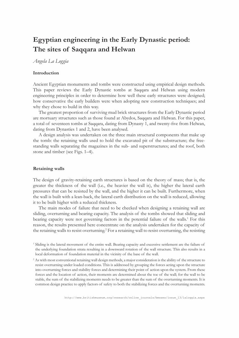
Egyptian engineering in the Early Dynastic period: The sites of Saqqara and Helwan Angela La Loggia
Introduction
Ancient Egyptian monuments and tombs were constructed using empirical design methods. This paper reviews the Early Dynastic tombs at Saqqara and Helwan using modern engineering principles in order to determine how well these early structures were designed; how conservative the early builders were when adopting new construction techniques; and why they chose to build in this way. The greatest proportion of surviving mud brick structures from the Early Dynastic period are mortuary structures such as those found at Abydos, Saqqara and Helwan. For this paper, a total of seventeen tombs at Saqqara, dating from Dynasty 1, and twenty-five from Helwan, dating from Dynasties 1 and 2, have been analysed. A design analysis was undertaken on the three main structural components that make up the tomb: the retaining walls used to hold the excavated pit of the substructure; the free-standing walls separating the magazines in the sub- and superstructures; and the roof, both stone and timber (see Figs. 1–4).
Retaining walls
The design of gravity-retaining earth structures is based on the theory of mass; that is, the greater the thickness of the wall (i.e., the heavier the wall is), the higher the lateral earth pressures that can be resisted by the wall, and the higher it can be built. Furthermore, when the wall is built with a lean-back, the lateral earth distribution on the wall is reduced, allowing it to be built higher with a reduced thickness. The main modes of failure that need to be checked when designing a retaining wall are sliding, overturning and bearing capacity. The analysis of the tombs showed that sliding and bearing capacity were not governing factors in the potential failure of the walls.1 For this reason, the results presented here concentrate on the analysis undertaken for the capacity of the retaining walls to resist overturning.2 For a retaining wall to resist overturning, the resisting
1 Sliding is the lateral movement of the entire wall. Bearing capacity and excessive settlement are the failure of the underlying foundation strata resulting in a downward rotation of the wall structure. This also results in a local deformation of foundation material in the vicinity of the base of the wall.
2 As with most conventional retaining wall design methods, a major consideration is the ability of the structure to resist overturning under loaded conditions. This is addressed by grouping the forces acting upon the structure into overturning forces and stability forces and determining their point of action upon the system. From these forces and the location of action, their moments are determined about the toe of the wall; for the wall to be stable, the sum of the stabilizing moments needs to be greater than the sum of the overturning moments. It is common design practice to apply factors of safety to both the stabilizing forces and the overturning moments.

http://www.britishmuseum.org/research/online_journals/bmsaes/issue_13/laloggia.aspx
2009 EGYPTIAN ENGINEERING 177
forces must be equal to or greater than the overturning forces. The design methodology adopted is based on the Coulomb Earth Pressure Theory.3 The results for the Saqqara and Helwan tombs are presented in Graphs 1–5.
SaqqaraOf the seventeen Dynasty 1 tombs at Saqqara, eight tombs had retaining walls, which were
analysed (see Graph 1). The other tombs had substructures cut into the rock strata, thus negating the need for retaining walls. Of these eight tombs, the graphed results demonstrate that seven tombs had adequate retaining walls, with the exception being Tomb 3038. Tomb 3038 underwent three construction phases, and the retaining walls had rubble three-quarters of the way up (Emery 1949, 87), which counterbalanced the lateral earth pressures acting on the wall.4
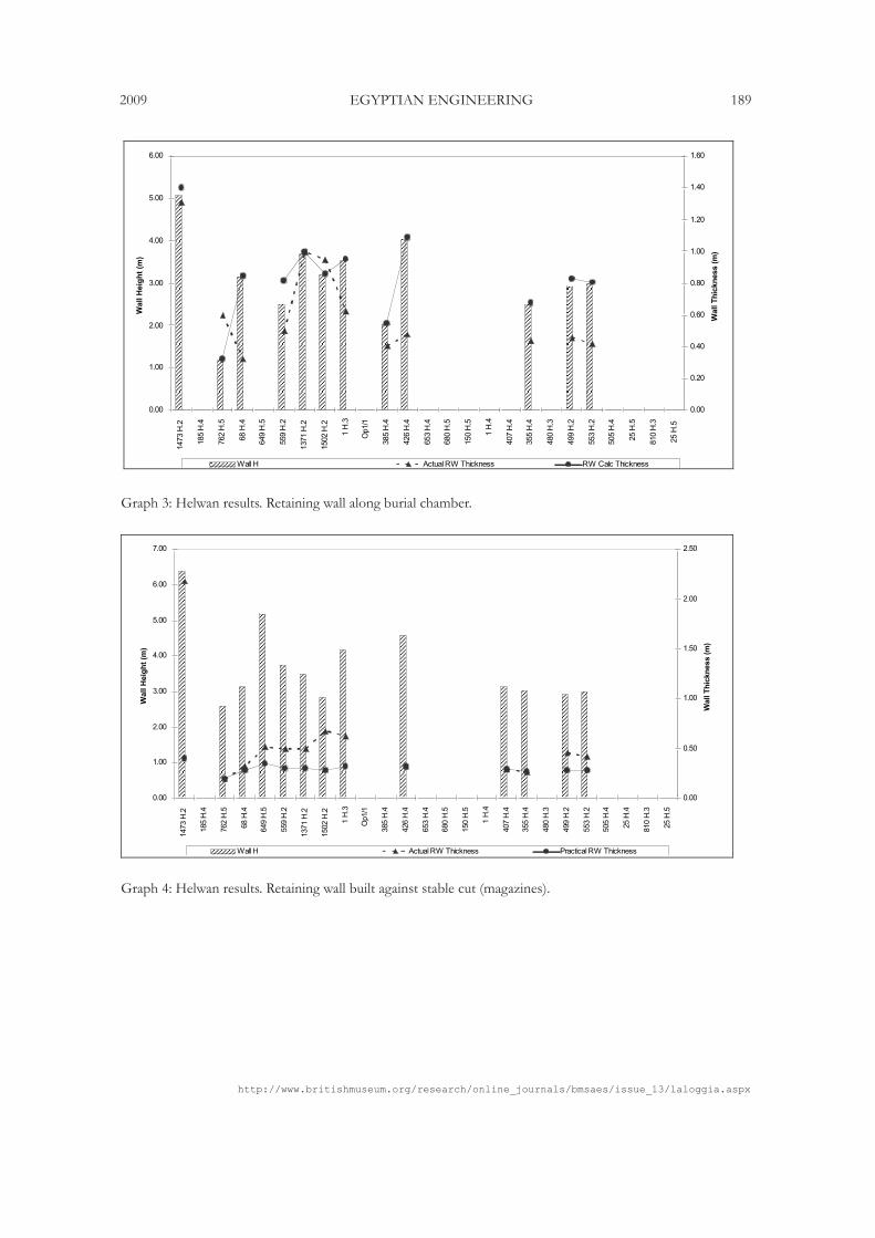
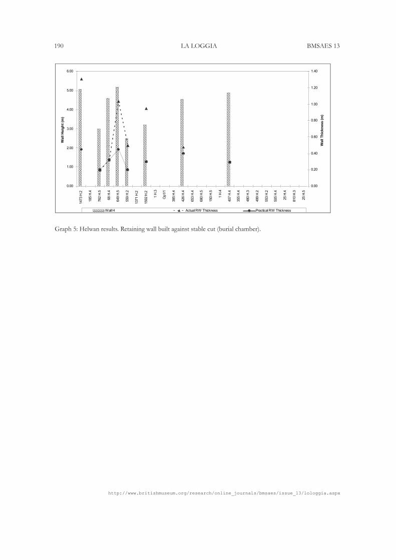
Helwan Of the twenty-five Early Dynastic tombs at Helwan, thirteen had retaining walls around the burial chamber and magazines, which were analysed. The initial results showed that the majority of the retaining walls should conceivably collapse (Graphs 2 and 3), but, as the walls are still in-situ, this was clearly not the case. As a number of the retaining walls are actually built in front of a stable self-supporting cut, rather than the loose sandy gravel strata, the pressure exerted by the earth behind the retaining wall is minimal. When these retaining walls were re-analysed to take into account the reduced earth pressure, the subsequent results show that they were more than adequate (Graphs 4 and 5). Further analysis of certain tombs showed that the Egyptians also made full use of buttress walls, which allowed them to build thinner retaining walls. One particular tomb that exhibits such resourcefulness is Tomb 1.H3 at Helwan (La Loggia 2008, 80–83, fig. 5; Saad 1947, 163–164, pls. 56–58). This practice demonstrates the ancient builders’ knowledge and understanding of their surrounding environment and geology in order to build effectively and efficiently.
3 In the design of any earth-retaining structure, there are two primary areas of concern: the lateral earth pressures; and foundation bearing capacity and overall stability. Both are based on the strength parameters of the soils: angle of internal friction (phi=φ), soil density, and cohesion. Active earth pressure is typically calculated for a wedge of soil trying to slide down a potential failure surface and being retained by the wall system. The basic assumptions for this active wedge theory were developed by Coulomb in 1776. This theory models the weight of the soil mass sliding along a theoretical plane of failure. The lateral earth pressure (Pa) is the net force required to hold the wedge of soil in place. If unrestrained, a soil embankment will slump to its angle of repose. Some soils, such as clays, have cohesion that enables vertical and near vertical faces to remain partially intact, but even these may slump under the softening influence of ground water. When an earth-retaining structure is constructed, it restricts this slump. The retained soil exerts an active pressure (Pa) on the wall. Overturning is resisted by the vertical load of the structure.
4 Whether the Egyptian builders of Tomb 3038 took this into consideration when building a less than adequate wall we will never know; however, one could argue that the rubble was put in place in order to compensate for the possibility of the wall failing as it was not originally constructed sufficiently thick. The chamber was small and did not appear to serve any significant purpose.
http://www.britishmuseum.org/research/online_journals/bmsaes/issue_13/lologgia.aspx
178 LA LOGGIA BMSAES 13
Free-standing wall design
Robustness is the ability of a wall of a certain thickness to stand up over a given height and length. The capacity of a wall will vary, depending on whether the wall is spanning vertically and if it is laterally supported (such as holding up a roof); what the length of the wall is; and if it is braced by cross walls. The free-standing walls for the tombs at Saqqara and Helwan were designed for robustness.5
SaqqaraFifteen Dynasty 1 tombs at Saqqara had free-standing walls, which were analysed. The
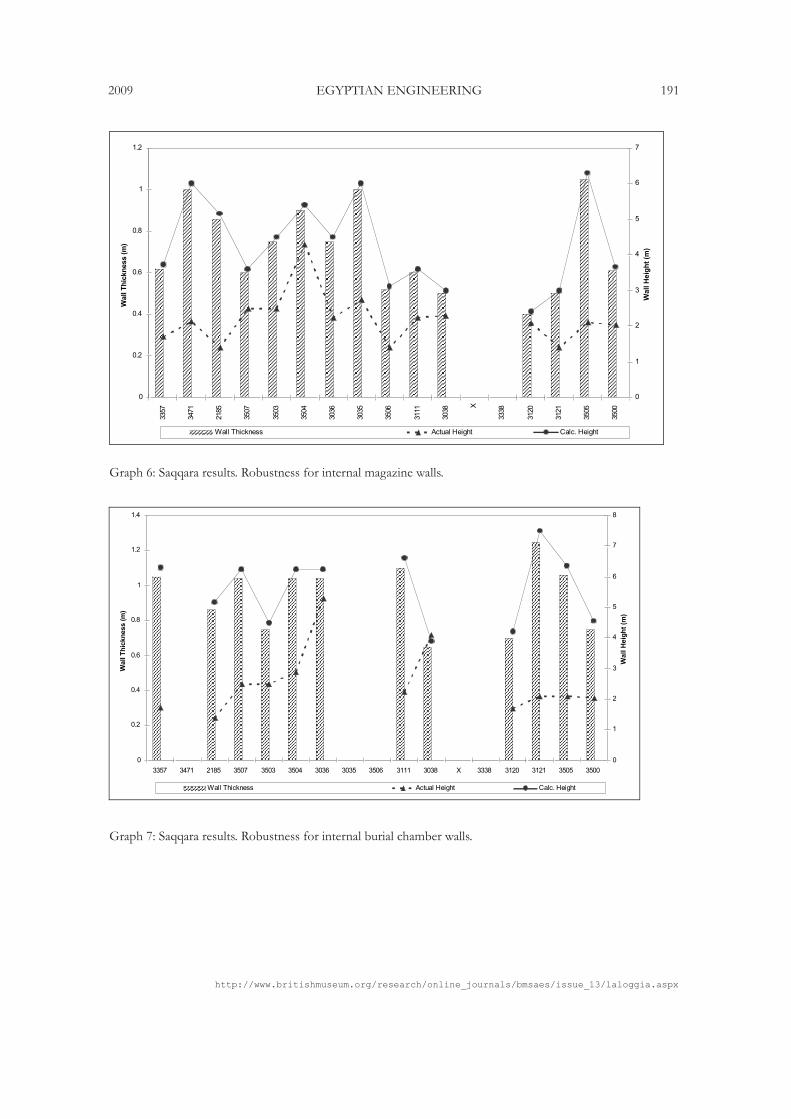
free-standing walls forming the magazine walls and those built around the burial chambers were analysed separately and the results are presented in Graphs 6–7. Analysis of the walls built to form the magazines in the Saqqara tombs showed that, in most cases, they were not overly conservative; that is to say, the walls were not much thicker than was structurally necessary. As a result, fewer mud bricks were required and construction time was shortened (Graph 6). Tombs 3471, 3035 (Hemaka) and 3505 (Merka), however, had substantially thicker walls. Were the tomb owners concerned that the walls might collapse, or did they feel the need for greater security by building much thicker walls than was structurally necessary? The answer may lie in the analysis of the burial chamber walls. The walls constructed around the burial chambers of the tombs at Saqqara, with the exceptions of Tombs 3036 and 3038, were all exceptionally thick (Graph 7). This result suggests that the thicker magazine and burial chamber walls were related to security, rather than concern for the walls collapsing, particularly as the majority of the tombs were entered by tunnelling under the superstructure and breaking through the walls rather than coming in through the roof (Emery 1954, 5). The thickening of these walls did not make them impregnable, but it would have made the task of tunnelling through them more arduous and risky for the tomb robber.
Helwan Of the twenty-five Early Dynastic tombs at Helwan, fourteen had free-standing walls, which were analysed and the results graphed (Graphs 8 and 9). The results show that the actual and calculated heights of the walls are almost the same in the majority of cases, with the exception of Tombs 1473.H.26 (Saad 1947, 110, pls. 39, 52; Köhler 2008, 123, fig. 16B), 559.H.2 (Saad 1947, 107–108, pls. 37, 45, 46; Köhler 2008, fig. 1C) and 1502.H.2 (Saad 1947, 110–111, pls. 40, 56, 61). Compared to the Saqqara tombs, those at Helwan appear to have been built much more economically, resulting in fewer material and labour resources being required in their construction. Despite this, the larger Helwan tombs clearly belonged to officials of considerable influence.
5 Design undertaken based on Australian Standards, AS3700:2001 Section 4.6, Design for Robustness.6 Köhler (2008) has noted that the tomb number was incorrectly labeled as 1374.H.2 in Saad’s 1947 report.
Saad’s original plan, as well as his field diary, confirms that this tomb is 1473.H.2.
http://www.britishmuseum.org/research/online_journals/bmsaes/issue_13/laloggia.aspx
2009 EGYPTIAN ENGINEERING 179
Roof design: Stone
The Early Dynastic tombs were most commonly roofed with timber, although there are instances where stone was used. For checking the capacity of the ancient stone roofs using modern engineering principles, information on the strength of the stone, namely limestone, was required in order to compare the maximum allowable span to the actual span.
SaqqaraTomb 2185 The remains of the stone roof of Saqqara Tomb 2185 were limestone slabs approximately 0.25m thick spanning the 1.6m distance.7 In order to determine how well the roof was designed, the maximum achievable span was calculated. It was assumed that sand and rubble had been placed over the roof to a depth of 0.5m to form the false floor. Based on the thickness of the slabs, they were capable of spanning a distance of 2.0m, indicating a very efficient design.
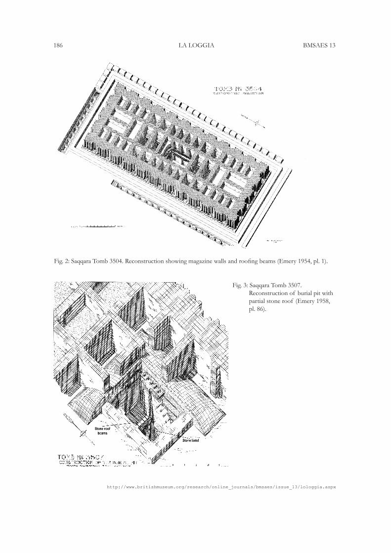
Tomb 3507 At the foot of the stairway leading to the burial chamber of Tomb 3507, a limestone lintel surmounted two rock-cut pilasters (Fig. 3) The lintel supported a stone beam roof which covered the southern area of the burial chamber. The limestone beams measured approximately 0.4 x 0.4m and spanned a distance of 1.47m. The full width of the burial chamber was 3.15m, and it had been partially roofed with timber (Emery 1949, 77).
The analysis concluded that the stone beams were capable of spanning a distance of 4.04m. As no additional weight had been applied to the beams from above, these beams were capable of spanning the full length of the burial chamber. This result shows that these early builders were cautious, which does not surprise, as this is one of the earliest roofs built of worked stone. It is more likely, however, that the owner chose to be buried with the traditional timber lining, including a timber roof.
Tomb 3121 The corridor leading to the burial chamber of Tomb 3121 at Saqqara was roofed with seven limestone beams, each measuring approximately 1.0 x 0.6m and 2.0m in length (Emery 1949, 118). While the actual width of the corridor is 1.15m, the calculations show that the maximum achievable span was approximately 5.3m if the beams were simply supporting their own weight. However, rubble and sand had been placed over the stone roof beams, and the additional load from the dead weight reduced the maximum allowable span to 3.3m.8
7 The break in the stone slabs is in fact due to robbers breaking through this part of the tomb, and not due to the roof collapsing. See Quibell 1923.
8 Whilst this is almost double the actual span, it is possible that the limestone was not of the best quality, or that the depth of rubble placed over the roof was greater than that shown in the tomb report, and thus a greater load was imposed on the roof than it was designed for. Of course, it could simply be that this was the size of the available beams.
http://www.britishmuseum.org/research/online_journals/bmsaes/issue_13/lologgia.aspx
180 LA LOGGIA BMSAES 13
Helwan Tomb 60.H.1 The stone roof of Tomb 60.H.1 at Helwan is still intact. The limestone slabs are 0.25m thick and span a 2m wide opening (Köhler 2008, 120, figs. 8B, 9–12). Calculating the theoretical allowable span of the slabs, assuming sand and rubble placed over the roof to a depth of 0.40m, resulted in a maximum span of 2.3m. As noted with the design of the retaining walls and free-standing walls for the Helwan tombs, the roof design follows a similar trend of efficient and economical design.
Interpretation of stone roof results Analysis of the stone roof beams in Saqqara Tombs 3507 and 3121, which were found in situ, confirmed that they were capable of spanning a distance greater than the actual span. The stone roof slabs of Tomb 2185 at Saqqara and Tomb 60.H.1 at Helwan were found to be slightly more than adequate for the given span. This shows that whilst some of the early designers and builders were perhaps cautious for structural, or even security reasons, they were certainly aware of the capacity of the limestone material they were working with.
Roof design: TimberIn the same way that the material properties of limestone were used in determining the maximum allowable span for tombs roofed with stone, so too an understanding of the flexural strength and density of timber was necessary in order to analyse the timber roofs (Smith 2004, 249). The timber beams and planks used for roofs of the Saqqara tombs were made of imported cedar from Lebanon (Emery 1961, 182), and this is most likely true of the larger Helwan tombs. Cedar was also used for the lining and paving of the burial chambers of some of the Saqqara tombs in the same manner in which limestone slabs were used in a small group of Helwan tombs (Köhler 2005, 23).
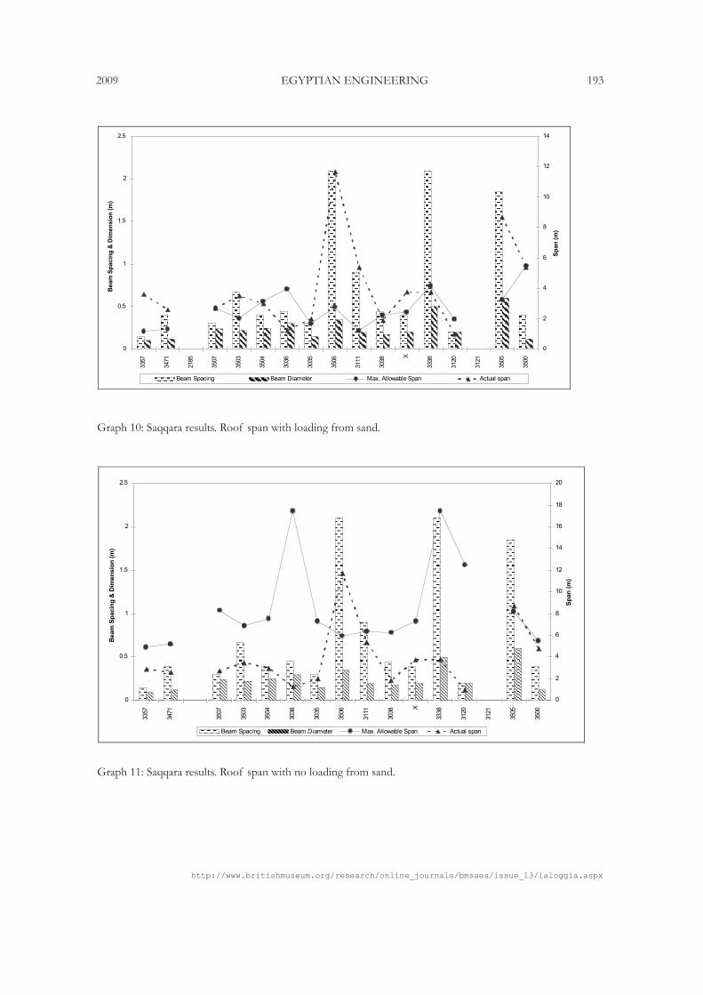
Saqqara The initial results showed that the roof timbers in only seven of the fifteen Dynasty 1 Saqqara tombs analysed were adequate (Graph 10). The huge load imposed on these timber roof structures from the sand and rubble placed above to form the false floor is the primary reason for this failure in the calculated results (cf. Fig. 2). When the load on the roof was removed (Graph 11), the results show the roofs to be more than capable of spanning the required distance with the exception of Tombs 3505 and 3506 (Fig. 4), which had roof spans of 8.2m and 11.6m respectively (Emery 1958, 9, 40). So did the roofs collapse as soon as they were loaded with sand? This seems unlikely, as the Egyptians would have built sturdier roofs in later tombs. Either the dimensions taken from the plans have not provided accurate data, or the actual span was reduced through the provision of roof supports in the form of columns or partition walls. In consideration of the first point, whilst the widths and heights of the walls were drawn to scale (Emery 1949, 1954, 1958), the detailing on the elevations showing roof beams and planks may have been drawn to provide a stylistic representation rather than precise information on the diameter and spacing of the beams (e.g. Fig. 1) Therefore, the roofs, where data was
http://www.britishmuseum.org/research/online_journals/bmsaes/issue_13/laloggia.aspx
2009 EGYPTIAN ENGINEERING 181
sourced solely from scaling of the elevation drawings,9 were re-designed to determine the impact of increasing beam diameters and reducing the spacing between beams.10 The analysis resulted in a further three tombs becoming adequate: Tombs 3503, X (Nebet-Ka) and 3111 (Sabu).11 The diameter of the timber beams was increased by a practical amount of only 10 cm. Modifying the dimensions and reducing the sand depth had minimal impact on the roof design of Tombs 3506 and 3505. As some roofs still show signs of failure, could supports have been used (Emery 1949, 74)?
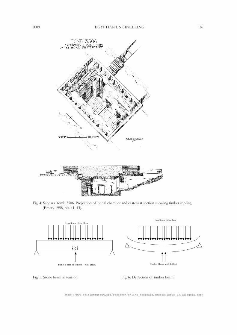
Tomb 3506 Tomb 3506 underwent three construction phases. During the final phase, the white plastered surface of the original burial chamber was covered with sand, on which a wooden floor was laid (Fig. 4). Emery (1958, 44) wrote: “after clearing the substructure and revealing the timber floor, the foundations of a large wooden structure could be traced in the southern half of the room. Its character can not be ascertained, but it rested directly on the wooden floor and was far too large for a coffin, measuring approximately 5.0 x 6.0m.” It is possible that this wooden structure also served to support the roof, with impressions on the floor possibly due to the heavy load applied to the timber shrine leaving distinct circular indentations.
Tomb 3038 Tomb 3038, like 3506, also underwent three construction phases. During the final design phase, the burial pit was divided into a series of rooms. These brick partitions served to reduce the overall span of the roof (Emery 1949, 91). This type of brick wall partitioning may have once also existed in other tombs and acted to support the roof, with all evidence now destroyed through fire and the passage of time.
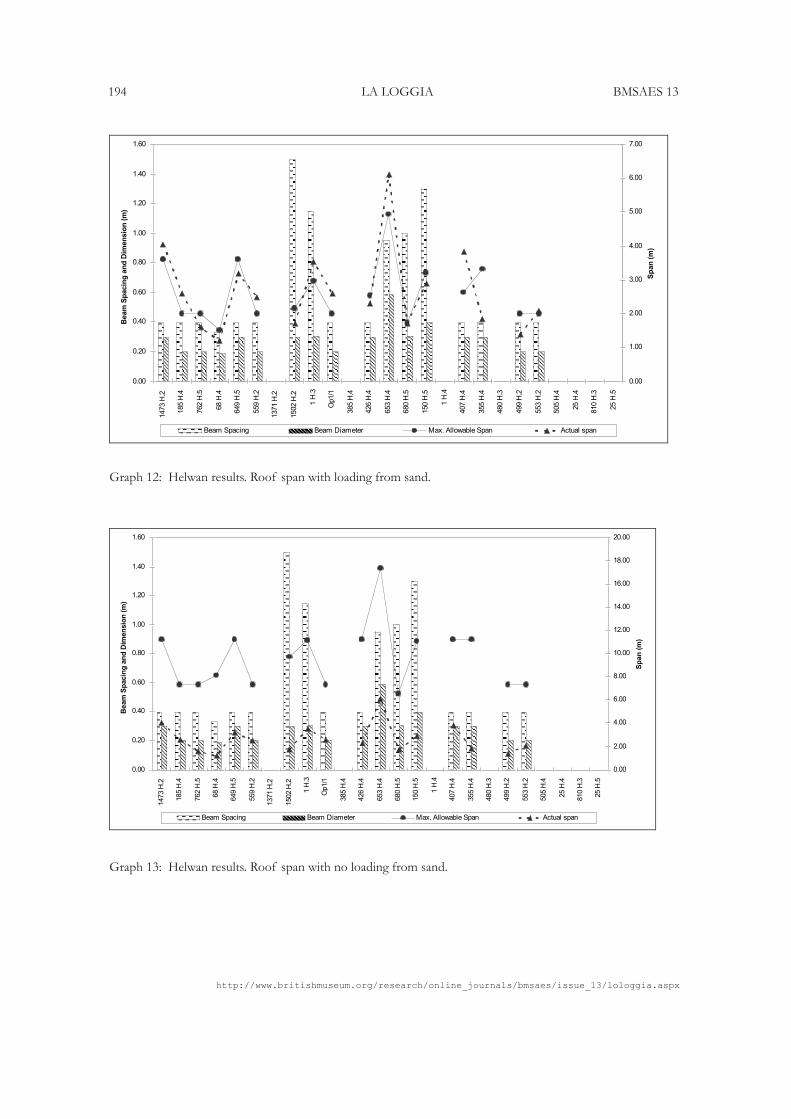
Helwan Whilst little or no evidence remains of the roofing structures of the Helwan tombs, the calculations were based on averaging the beam dimensions of those tombs for which data is available.12 The depth of sand placed on top of the roofs to form the false floor was assumed to be the height from the bottom of the ledge where the roof beams were placed to ground level. The results show that of the seventeen Helwan tombs analysed, eight were capable of spanning the required distance with the full weight of sand and rubble placed on top of them (Graph 12). If no sand was placed over the roofs, they were all capable of spanning the required distance (Graph13). As with the Saqqara tombs, increasing the beam diameter and reducing the span between the beams resulted in the roofs of Helwan Tombs 559.H.2, 1.H.3 and 553.H.2 (Saad 1947,
9 Tombs 3357 (Hor-Aha), 3471 and 3505 were not redesigned, as the beam dimensions were provided in Emery’s excavation reports. See Emery 1939, 1958.
10 Beams spaced closer together would have the total load distributed over a greater number of beams, and thus each beam would have been subjected to smaller loads.
11 For Tomb 3111, the roofs over the magazines became adequate but the much larger span of the burial chamber resulted in the beams still being inadequate.
12 Average beam dimensions of the Saqqara tombs was also used as a guide for the beam diameter and beam spacing used in analyzing the roofs at Helwan.
http://www.britishmuseum.org/research/online_journals/bmsaes/issue_13/lologgia.aspx
182 LA LOGGIA BMSAES 13
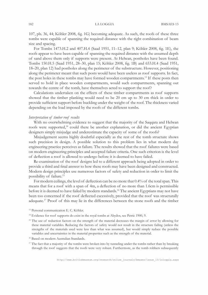
107, pls. 36, 44; Köhler 2008, fig. 1G) becoming adequate. As such, the roofs of these three tombs were capable of spanning the required distance with the right combination of beam size and spacing. For Tombs 1473.H.2 and 407.H.4 (Saad 1951, 11–12, plan 9; Köhler 2008, fig. 1E), the roofs appear to have been capable of spanning the required distance with the assumed depth of sand above them only if supports were present. At Helwan, postholes have been found. Tombs 150.H.5 (Saad 1951, 28–30, plan 15; Köhler 2008, fig. 1B) and 653.H.4 (Saad 1951, 18–20, plan 12) had postholes along the perimeter of the substructure. However, positioning along the perimeter meant that such posts would have been useless as roof supports. In fact, the post holes in these tombs may have formed wooden compartments.13 If these posts then served to hold in place wooden compartments, would such compartments, spanning out towards the centre of the tomb, have themselves acted to support the roof? Calculations undertaken on the effects of these timber compartments as roof supports showed that the timber planking would need to be 20 cm up to 30 cm thick in order to provide sufficient support before buckling under the weight of the roof. The thickness varied depending on the load imposed by the roofs of the different tombs.
Interpretation of timber roof results With no overwhelming evidence to suggest that the majority of the Saqqara and Helwan roofs were supported,14 could there be another explanation, or did the ancient Egyptian designers simply misjudge and underestimate the capacity of some of the roofs? Misjudgement seems highly doubtful especially as the rest of the tomb structure shows such precision in design. A possible solution to this problem lies in what modern day engineering practice perceives as failure. The results showed that the roof failures were based on modern engineering principles and accepted failure criteria. One such criterion is the level of deflection a roof is allowed to undergo before it is deemed to have failed. Re-examination of the roof designs led to a different approach being adopted in order to provide a third and final answer to how these roofs may have been designed and constructed. Modern design principles use numerous factors of safety and reduction in order to limit the possibility of failure.15 For modern ceilings, the level of deflection can be no more that 0.4% of the total span. This means that for a roof with a span of 4m, a deflection of no more than 1.6cm is permissible before it is deemed to have failed by modern standards.16 The ancient Egyptians may not have been too concerned if the roof deflected excessively, provided that the roof was structurally adequate.17 Proof of this may lie in the differences between the stone roofs and the timber
13 Personal communication E. C. Köhler.14 Evidence for roof supports do exist in the royal tombs at Abydos, see Petrie 1900, 9.15 The use of reduction factors on the strength of the material decreases the margin of error by allowing for
these material variables. Reducing the factors of safety would not result in the structure failing (unless the strengths of the materials used were less than what was assumed), but would simply reduce the possible variables and uncertainties in the material properties such as the strength of the material.
16 Based on modern Australian Standards. 17 The fact that a majority of the tombs were broken into by tunneling under the tombs rather than by breaking
through the roof suggests that the roofs were very robust. Furthermore, as the tomb robbers subsequently
http://www.britishmuseum.org/research/online_journals/bmsaes/issue_13/laloggia.aspx
2009 EGYPTIAN ENGINEERING 183
roofs, and the Egyptians’ understanding of how these two materials behaved. As discussed earlier, the stone roofs were more than adequate for spanning the required distance when analysed using modern engineering principles. Stone is strong under compression but weak in tension. This means that stone will not deflect when a load is applied—such as the placement of sand forming the false floor—but will crack along the base (Fig. 5).
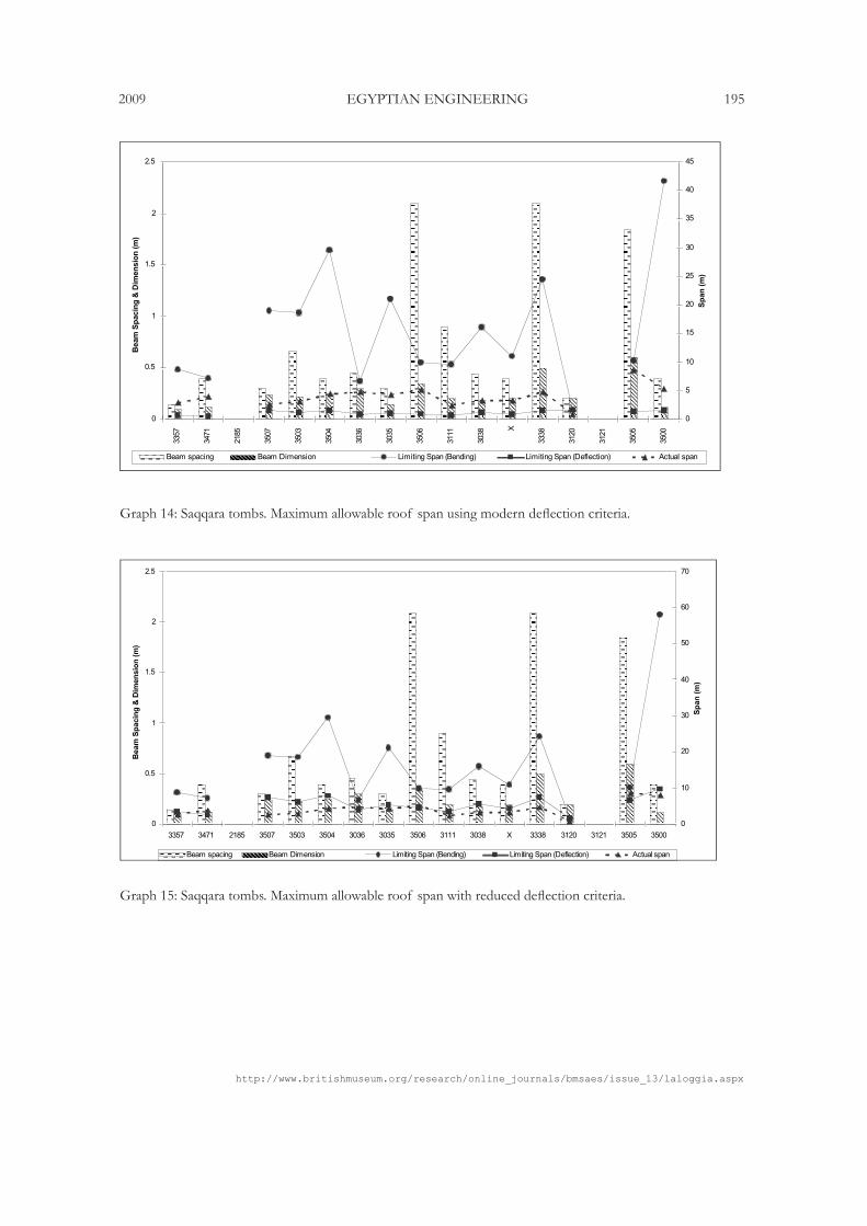
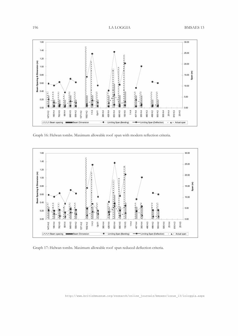
Timber, unlike stone, is tensile and will deflect when a load is applied (Fig. 6). The timber roofs were re-analysed. The level of deflection and strength of the roof (bending) were examined independently and the results graphed. Graph 14 shows that the roofs were strong enough to span the required distance, but would be deflecting beyond acceptable modern standards. Increasing the level of allowable deflection resulted in all the roofs of the Dynasty 1 tombs at Saqqara becoming adequate (see Graph 15), with the exception of Tombs 3506 and 3505 due to their large spans.18 These tombs most likely had partition walls similar to those found in Tomb 3038, or else timber supports. Similar results were found upon re-examination of the Helwan tombs. The use of modern deflection criteria resulted in a large proportion of the roofs failing under deflection (see Graph 16). However, when the level of allowable deflection was increased (see Graph 17), the Helwan roofs were shown to be adequate.
Conclusions
From the analysis of the retaining walls, free-standing walls and roofs, it is evident that the ancient Egyptians built these early structures based on their experience, possibly gained from past failures. The results have shown that the Egyptian builders had a good understanding of the local geology, as seen by the care taken in retaining wall construction. The designs showed that these builders compensated for walls built against rock compared to those built against the gravel strata, and also made full use of buttress walls. The free-standing walls separating the magazines and burial chambers showed differences in thickness between those built at Saqqara and those at Helwan. The Helwan tombs were less conservative, but still structurally adequate, leading to a saving of resources. However, whilst the Saqqara walls were thicker, the trends show that this may have had more to do with security, as demonstrated by the thickening of walls built around the burial chamber of these tombs. Finally, the design of the roofs shows that the Egyptians constructed them with a thorough understanding of the way certain materials, such as stone and timber, behave under imposed loads. Whilst not designed to the same level of conservatism dictated by modern standards, they were certainly adequate and fit for purpose. So why did the ancient Egyptians build in this way? Based on the research undertaken thus far, the construction methods of the early Egyptians were practical from an engineering
set fire to the chambers, this would seem to suggest that the roofs were intact, perhaps with a high degree of deflection, but intact all the same.
18 Tomb 3505 had a roof span of 8.2 m, whilst 3506 had a roof span of 11.6 m.
http://www.britishmuseum.org/research/online_journals/bmsaes/issue_13/lologgia.aspx
184 LA LOGGIA BMSAES 13
perspective and demonstrate an effective use of resources through a good understanding of the surrounding environment and the capacity of the materials they utilized. This analysis ultimately aims to demonstrate the high degree of engineering knowledge exhibited by the ancient Egyptian builders 5000 years ago.
AcknowledgementsWe are grateful to the Egypt Exploration Society for permission to reproduce selected plates from the works of W. B. Emery.
Select Bibliography
Emery, W. B. 1938. Excavations at Saqqara: The tomb of Hemaka. Cairo.———. 1939. Excavations at Saqqara: Hor-Aha. Cairo.———. 1949. Great tombs of the First Dynasty I. Cairo.———. 1954. Great tombs of the First Dynasty II. London.———. 1958. Great tombs of the First Dynasty III. London. ———. 1961. Archaic Egypt. Edinburgh.Köhler, E. C. 1998. Excavations at Helwan: New insights into Early Dynastic stone masonry.
BACE 9: 65–72.———. 2000. Excavations in the Early Dynastic cemetery at Helwan: A preliminary report
of the 1998/99 and 1999/2000 seasons. BACE 11:83–92.———. 2003. The new excavations in the Early Dynastic necropolis at Helwan. Archéo-Nil
13:16–27.———. 2004. On the origins of Memphis: The new excavations in the Early Dynastic
necropolis at Helwan. In Egypt at its origins: Studies in memory of Barbara Adams: Proceedings of the International Conference, “Origin of the state: Predynastic and Early Dynastic Egypt,” Kraków, 28 August–1st September 2002, S. Hendrickx, R. F. Friedman, K. M. Ciałowicz and M. Chłodnicki (eds.), OLA 138, 295–315. Leuven; Paris; Dudley.
———. 2005. Helwan I: Excavations in the Early Dynastic cemetery 1997/98. SAGA 24. Heidelberg.———. 2008. The Helwan cemetery. Archéo-Nil 18: 113–30.La Loggia, A. 2008. The use of stone in Early Dynastic Egypt. Bulletin of the Australia Centre
for Egyptology 19: 73–95.Petrie, W. M. F. 1900. The royal tombs of the First Dynasty I. Egypt Exploration Fund 18. London. Quibell, J. E. 1923. Excavations at Saqqara (1912–1914): Archaic mastabas. Cairo.Saad, Z. Y. 1947. Royal excavations at Saqqara and Helwan (1942–1945). SASAE 3: 1–25.———. 1951. Royal excavations at Helwan (1945–1947). SASAE 14: 1–52.———. 1969. The excavations at Helwan: Art and civilization of the 1st and 2nd Egyptian dynasties.
Norman, OK. Smith, C. B. 2004. How the great pyramid was built. New York.Wood, W. 1987. The stone tombs of Helwan. Journal of Egyptian Archaeology 73: 59–70.
http://www.britishmuseum.org/research/online_journals/bmsaes/issue_13/laloggia.aspx
2009 EGYPTIAN ENGINEERING 185
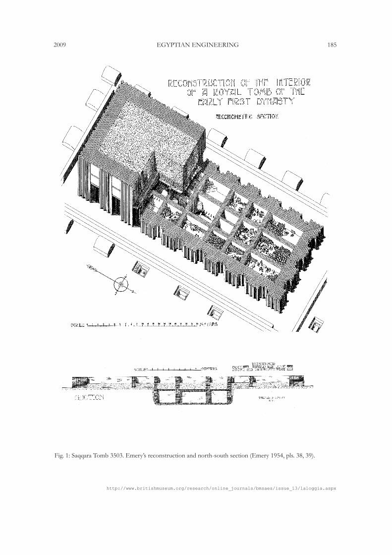
Fig. 1: Saqqara Tomb 3503. Emery’s reconstruction and north-south section (Emery 1954, pls. 38, 39).
http://www.britishmuseum.org/research/online_journals/bmsaes/issue_13/lologgia.aspx
186 LA LOGGIA BMSAES 13
Fig. 3: Saqqara Tomb 3507. Reconstruction of burial pit with partial stone roof (Emery 1958, pl. 86).
Fig. 2: Saqqara Tomb 3504. Reconstruction showing magazine walls and roofing beams (Emery 1954, pl. 1).
http://www.britishmuseum.org/research/online_journals/bmsaes/issue_13/laloggia.aspx
2009 EGYPTIAN ENGINEERING 187
Fig. 4: Saqqara Tomb 3506. Projection of burial chamber and east-west section showing timber roofing (Emery 1958, pls. 41, 43).
Fig. 5: Stone beam in tension. Fig. 6: Deflection of timber beam.
Load from false floor
Stone Beam in tension – will crack
Tim ber Beam will de flect
Load from false floor

http://www.britishmuseum.org/research/online_journals/bmsaes/issue_13/lologgia.aspx
188 LA LOGGIA BMSAES 13
Graph 1: Saqqara results. Retaining wall along magazines.
Graph 2: Helwan results. Retaining wall along magazines.
Retaining Wall along Magazine
0
0.5
1
1.5
2
2.5
3
3357
3471
2185
3507
3503
3504
3036
3035
3506
3111
3038 X
3338
3120
3121
3505
3500
Wall H
eig
ht
(m)
0
0.1
0.2
0.3
0.4
0.5
0.6
0.7
0.8
0.9
1
Wall T
hic
kn
ess (
m)
Wall H Actual RW Thickness RW Calc Thickness
Graph 1: Saqqara Results - Retaining Wall along Magazines
Retaining Walls along Magazine
0.00
1.00
2.00
3.00
4.00
5.00
6.00
7.00
1473 H
.2
185 H
.4
762 H
.5
68 H
.4
649 H
.5
559 H
.2
1371 H
.2
1502 H
.2
1 H
.3
Op1/1
385 H
.4
426 H
.4
653 H
.4
680 H
.5
150 H
.5
1 H
.4
407 H
.4
355 H
.4
480 H
.3
499 H
.2
553 H
.2
505 H
.4
25 H
.4
810 H
.3
25 H
.5
Wall H
eig
ht
(m)
0.00
0.50
1.00
1.50
2.00
2.50
Wall T
hic
kn
ess (
m)
Wall H Actual RW Thickness RW Calc Thickness
Graph 1: Helwan Results – Retaining Wall along Magazines
http://www.britishmuseum.org/research/online_journals/bmsaes/issue_13/laloggia.aspx
2009 EGYPTIAN ENGINEERING 189
Graph 3: Helwan results. Retaining wall along burial chamber.
Retaining Wall along Burial
0.00
1.00
2.00
3.00
4.00
5.00
6.00
1473 H
.2
185 H
.4
762 H
.5
68 H
.4
649 H
.5
559 H
.2
1371 H
.2
1502 H
.2
1 H
.3
Op1/1
385 H
.4
426 H
.4
653 H
.4
680 H
.5
150 H
.5
1 H
.4
407 H
.4
355 H
.4
480 H
.3
499 H
.2
553 H
.2
505 H
.4
25 H
.5
810 H
.3
25 H
.5
Wall H
eig
ht
(m)
0.00
0.20
0.40
0.60
0.80
1.00
1.20
1.40
1.60
Wall T
hic
kn
ess (
m)
Wall H Actual RW Thickness RW Calc Thickness
Graph 1: Helwan Results – Retaining Wall along Burial Chamber
Retaining Wall built against Rock Cut (Magazines)
0.00
1.00
2.00
3.00
4.00
5.00
6.00
7.00
1473 H
.2
185 H
.4
762 H
.5
68 H
.4
649 H
.5
559 H
.2
1371 H
.2
1502 H
.2
1 H
.3
Op1/1
385 H
.4
426 H
.4
653 H
.4
680 H
.5
150 H
.5
1 H
.4
407 H
.4
355 H
.4
480 H
.3
499 H
.2
553 H
.2
505 H
.4
25 H
.4
810 H
.3
25 H
.5
Wall H
eig
ht
(m)
0.00
0.50
1.00
1.50
2.00
2.50
Wall T
hic
kn
ess (
m)
Wall H Actual RW Thickness Practical RW Thickness
Graph 1: Helwan Results – Retaining Wall built against stable cut (Magazines)
Graph 4: Helwan results. Retaining wall built against stable cut (magazines).
http://www.britishmuseum.org/research/online_journals/bmsaes/issue_13/lologgia.aspx
190 LA LOGGIA BMSAES 13
Retaining Wall built against Rock Cut (Burial Chamber)
0.00
1.00
2.00
3.00
4.00
5.00
6.00
1473 H
.2
185 H
.4
762 H
.5
68 H
.4
649 H
.5
559 H
.2
1371 H
.2
1502 H
.2
1 H
.3
Op1/1
385 H
.4
426 H
.4
653 H
.4
680 H
.5
150 H
.5
1 H
.4
407 H
.4
355 H
.4
480 H
.3
499 H
.2
553 H
.2
505 H
.4
25 H
.4
810 H
.3
25 H
.5
Wall H
eig
ht
(m)
0.00
0.20
0.40
0.60
0.80
1.00
1.20
1.40
Wall T
hic
kn
ess (
m)
Wall H Actual RW Thickness Practical RW Thickness
Graph 1: Helwan Results – Retaining Wall built against stable cut (Burial Chamber)
Graph 5: Helwan results. Retaining wall built against stable cut (burial chamber).
http://www.britishmuseum.org/research/online_journals/bmsaes/issue_13/laloggia.aspx
2009 EGYPTIAN ENGINEERING 191
Graph 7: Saqqara results. Robustness for internal burial chamber walls.
Robustness - Internal Walls to Burial Chamber
0
0.2
0.4
0.6
0.8
1
1.2
1.4
3357 3471 2185 3507 3503 3504 3036 3035 3506 3111 3038 X 3338 3120 3121 3505 3500
Wall T
hic
kn
ess (
m)
0
1
2
3
4
5
6
7
8
Wall H
eig
ht
(m)
Wall Thickness Actual Height Calc. Height
Graph 1: Saqqara Results - Robustness for Internal Burial Chamber Walls
Robustness - Internal Magazine Walls
0
0.2
0.4
0.6
0.8
1
1.2
3357
3471
2185
3507
3503
3504
3036
3035
3506
3111
3038 X
3338
3120
3121
3505
3500
Wall T
hic
kn
ess (
m)
0
1
2
3
4
5
6
7
Wall H
eig
ht
(m)
Wall Thickness Actual Height Calc. Height
Graph 1: Saqqara Results - Robustness for Internal Magazine Walls
Graph 6: Saqqara results. Robustness for internal magazine walls.

http://www.britishmuseum.org/research/online_journals/bmsaes/issue_13/lologgia.aspx
192 LA LOGGIA BMSAES 13
Graph 9: Helwan results. Robustness for internal burial chamber walls.
Robustness - Internal Walls to Burial Chamber
0.00
0.10
0.20
0.30
0.40
0.50
0.60
1473 H
.2
185 H
.4
762 H
.5
68 H
.4
649 H
.5
559 H
.2
1371 H
.2
1502 H
.2
1 H
.3
385 H
.4
426 H
.4
680 H
.5
150 H
.5
1 H
.4
407 H
.4
355 H
.4
480 H
.3
499 H
.2
553 H
.2
25 H
.4
810 H
.3
25 H
.5
Wall T
hic
kn
ess (
m)
0.00
0.50
1.00
1.50
2.00
2.50
3.00
3.50
Wall H
eig
ht
(m)
Wall Thickness Actual Height Calc. Height
Graph 8: Helwan results. Robustness for internal magazine walls.
Robustness - Internal Magazine Walls
0.00
0.10
0.20
0.30
0.40
0.50
0.60
0.70
0.80
0.90
1.00
1473 H
.2
185 H
.4
762 H
.5
68 H
.4
649 H
.5
559 H
.2
1371 H
.2
1502 H
.2
1 H
.3
385 H
.4
426 H
.4
680 H
.5
150 H
.5
1 H
.4
407 H
.4
355 H
.4
480 H
.3
499 H
.2
553 H
.2
25 H
.4
810 H
.3
25 H
.5
Wall T
hic
kn
ess (
m)
0.00
1.00
2.00
3.00
4.00
5.00
6.00
Wall H
eig
ht
(m)
Wall Thickness Actual Height Calc. Height
Graph 1: Helwan Results - Robustness for Internal Magazine Walls
http://www.britishmuseum.org/research/online_journals/bmsaes/issue_13/laloggia.aspx
2009 EGYPTIAN ENGINEERING 193
Graph 10: Saqqara results. Roof span with loading from sand.
Graph 11: Saqqara results. Roof span with no loading from sand.
Roof Spans with Loading from Sand
0
0.5
1
1.5
2
2.53357
3471
2185
3507
3503
3504
3036
3035
3506
3111
3038 X
3338
3120
3121
3505
3500
Beam
Sp
acin
g &
Dim
en
sio
n (
m)
0
2
4
6
8
10
12
14
Sp
an
(m
)
Beam Spacing Beam Diameter Max. Allowable Span Actual span
Roof Spans with No Loading from Sand
0
0.5
1
1.5
2
2.5
3357
3471
3507
3503
3504
3036
3035
3506
3111
3038 X
3338
3120
3121
3505
3500
Beam
Sp
acin
g &
Dim
en
sio
n (
m)
0
2
4
6
8
10
12
14
16
18
20
Sp
an
(m
)
Beam Spacing Beam Diameter Max. Allowable Span Actual span
http://www.britishmuseum.org/research/online_journals/bmsaes/issue_13/lologgia.aspx
194 LA LOGGIA BMSAES 13
Roof Spans with Loading from Sand
0.00
0.20
0.40
0.60
0.80
1.00
1.20
1.40
1.60
1473 H
.2
185 H
.4
762 H
.5
68 H
.4
649 H
.5
559 H
.2
1371 H
.2
1502 H
.2
1 H
.3
Op1/1
385 H
.4
426 H
.4
653 H
.4
680 H
.5
150 H
.5
1 H
.4
407 H
.4
355 H
.4
480 H
.3
499 H
.2
553 H
.2
505 H
.4
25 H
.4
810 H
.3
25 H
.5
Beam
Sp
acin
g a
nd
Dim
en
sio
n (
m)
0.00
1.00
2.00
3.00
4.00
5.00
6.00
7.00
Sp
an
(m
)
Beam Spacing Beam Diameter Max. Allowable Span Actual span
Graph 12: Helwan results. Roof span with loading from sand.
Roof Spans with No Loading from Sand
0.00
0.20
0.40
0.60
0.80
1.00
1.20
1.40
1.60
1473 H
.2
185 H
.4
762 H
.5
68 H
.4
649 H
.5
559 H
.2
1371 H
.2
1502 H
.2
1 H
.3
Op1/1
385 H
.4
426 H
.4
653 H
.4
680 H
.5
150 H
.5
1 H
.4
407 H
.4
355 H
.4
480 H
.3
499 H
.2
553 H
.2
505 H
.4
25 H
.4
810 H
.3
25 H
.5
Beam
Sp
acin
g a
nd
Dim
en
sio
n (
m)
0.00
2.00
4.00
6.00
8.00
10.00
12.00
14.00
16.00
18.00
20.00
Sp
an
(m
)
Beam Spacing Beam Diameter Max. Allowable Span Actual span
Graph 13: Helwan results. Roof span with no loading from sand.
http://www.britishmuseum.org/research/online_journals/bmsaes/issue_13/laloggia.aspx
2009 EGYPTIAN ENGINEERING 195
Graph 14: Saqqara tombs. Maximum allowable roof span using modern deflection criteria.
Graph 15: Saqqara tombs. Maximum allowable roof span with reduced deflection criteria.
Maximum Allowable Roof Span - Bending & Deflection
Deflection Coefficient 0.04
0
0.5
1
1.5
2
2.5
3357
3471
2185
3507
3503
3504
3036
3035
3506
3111
3038 X
3338
3120
3121
3505
3500
Beam
Sp
acin
g &
Dim
en
sio
n (
m)
0
5
10
15
20
25
30
35
40
45
Sp
an
(m
)
Beam spacing Beam Dimension Limiting Span (Bending) Limiting Span (Deflection) Actual span
Maximum Allowable Roof Span - Bending & Deflection
Deflection Coefficient 0.5
0
0.5
1
1.5
2
2.5
3357 3471 2185 3507 3503 3504 3036 3035 3506 3111 3038 X 3338 3120 3121 3505 3500
Beam
Sp
acin
g &
Dim
en
sio
n (
m)
0
10
20
30
40
50
60
70
Sp
an
(m
)
Beam spacing Beam Dimension Limiting Span (Bending) Limiting Span (Deflection) Actual span
http://www.britishmuseum.org/research/online_journals/bmsaes/issue_13/lologgia.aspx
196 LA LOGGIA BMSAES 13
Maximum Allowable Roof Span - Bending & Deflection
Deflection Coefficient 0.04
0.00
0.20
0.40
0.60
0.80
1.00
1.20
1.40
1.60
1473 H
.2
185 H
.4
762 H
.5
68 H
.4
649 H
.5
559 H
.2
1371 H
.2
1502 H
.2
1 H
.3
Op1/1
385 H
.4
426 H
.4
653 H
.4
680 H
.5
150 H
.5
1 H
.4
407 H
.4
355 H
.4
480 H
.3
499 H
.2
553 H
.2
505 H
.4
25 H
.4
810 H
.3
25 H
.5
Beam
Sp
acin
g &
Dim
en
sio
n (
m)
0.00
5.00
10.00
15.00
20.00
25.00
30.00
Sp
an
(m
)
Beam spacing Beam Dimension Limiting Span (Bending) Limiting Span (Deflection) Actual span
Graph 16: Helwan tombs. Maximum allowable roof span with modern reflection criteria.
Maximum Allowable Roof Span - Bending & Deflection
Deflection Coefficient 0.5
0.00
0.20
0.40
0.60
0.80
1.00
1.20
1.40
1.60
1473 H
.2
185 H
.4
762 H
.5
68 H
.4
649 H
.5
559 H
.2
1371 H
.2
1502 H
.2
1 H
.3
Op1/1
385 H
.4
426 H
.4
653 H
.4
680 H
.5
150 H
.5
1 H
.4
407 H
.4
355 H
.4
480 H
.3
499 H
.2
553 H
.2
505 H
.4
25 H
.4
810 H
.3
25 H
.5
Beam
Sp
acin
g &
Dim
en
sio
n (
m)
0.00
5.00
10.00
15.00
20.00
25.00
30.00
Sp
an
(m
)
Beam spacing Beam Dimension Limiting Span (Bending) Limiting Span (Deflection) Actual span
Graph 17: Helwan tombs. Maximum allowable roof span reduced deflection criteria.