Embed Size (px)
Citation preview

Tasmanian Networks Pty Ltd (ABN 24 167 357 299)
Standard
Extra High Voltage (EHV) Disconnector and EarthSwitch Standard
R586396
Version 1.0, June 2018

Tasmanian Networks Pty Ltd (ABN 24 167 357 299)
AuthorisationsAction Name and title DatePrepared by Michael Verrier, Senior Asset Strategy Engineer June 2018
Reviewed bySantosh Dhakal, Asset Engineer June 2018
Authorised by Darryl Munro, Asset Strategy Team Leader June 2018Review cycle 30 months
ResponsibilitiesThis document is the responsibility of the Asset Strategy Team, Tasmanian Networks Pty Ltd, ABN 24 167 357 299 (hereafter referred to as "TasNetworks") .
Please contact the Asset Strategy Leader with any queries or suggestions.
• Implementation All TasNetworks staff and contractors.
• Compliance All group managers.
Minimum RequirementsThe requirements set out in TasNetworks ’ documents are minimum requirements that must be compliedwith by all TasNetworks team members, contractors, and other consultants.
The end user is expected to implement any practices which may not be stated but which can be reasonablyregarded as good practices relevant to the objective of this document.
© Tasmanian Networks Pty Ltd 2014

Page 3 of 22
EHV Disconnector and Earth Switch Standard
Record of revisionsSection number Details
Entire doc Copied over verbatim from superseded Transend to TasNetworks template.Updated Transend to TasNetworks document reference numbers where knownincluding Australian Standards.

Page 4 of 22
EHV Disconnector and Earth Switch Standard
Table of contentsAuthorisations...............................................................................................................................................2
Responsibilities............................................................................................................................................. 2
Minimum Requirements...............................................................................................................................2
List of tables..................................................................................................................................................5
List of figures.................................................................................................................................................6
1.....................................................................................................................................................General7
1.1..................................................................................................................................Purpose7
1.2..........................................................................................................................................Scope7
1.3................................................................................................................................Objective7
1.4.................................................................................................... Certificate of conformance7
1.5............................................................................................................................ Precedence7
1.6................................................................................................................................Deviation8
1.7............................................................................................................................. References8
1.7.1.......................................................................................................TasNetworks standards8
1.7.2.................................................................................................................. Other standards7
2.................................................................................................................................... Service conditions8
3................................................................................................................................Design requirements8
3.1....................................................................................................................... General design10
3.2...................................................................................................................Earthing switches11
3.3......................................................................................................Interlocking requirements12
3.4........................................................................................................................Post insulators12
3.5............................................................................................................Primary line terminals12

Page 5 of 22
EHV Disconnector and Earth Switch Standard
3.6...................................................................................................................Auxiliary switches12
3.7......................................................................................Local control and operating cubicles13
4..................................................................................................................................Other requirements13
4.1..............................................................................................................General construction13
4.2..................................................................................................................................Earthing13
4.3...........................................................................................................................Special tools14
4.4................................................................................................Documentation requirements14
4.5............................................................................................................................Nameplates14
5......................................................................................................................................................Testing15
5.1...............................................................................................................................Type tests15
5.2..........................................................................................................................Routine tests15
6..................................................................................................................................................Packaging16
7..................................................................................... Data for asset management information system16
8.........................................................................................................Maintenance procedures and plans16
9...................................................................................................Information to be provided with tender16
10............................................................................................................................................Deliverables16
11.............................................................................................................................................Hold points16
12......................................................................................................................Pantograph disconnectors17
List of tablesTable 1......................................................................................... Parameters for disconnectors
8

Page 6 of 22
EHV Disconnector and Earth Switch Standard
List of figuresFigure 1.............................................................................................................Earth switch flag
11

Page 7 of 22
EHV Disconnector and Earth Switch Standard
1 General
1.1 PurposeTo define the requirements from extra high voltage (EHV) disconnectors (hereafter referred to asdisconnectors) and earth switches, under the responsibility of Tasmanian Networks Pty Ltd (hereafterreferred to as TasNetworks).
1.2 ScopeThis standard specifies the requirements for the design, manufacture, construction, testing atmanufacturer’s works, secure packaging, supply, transportation and delivery to site, with completedocumentation, of disconnectors and earth switches.
1.3 ObjectiveTasNetworks has developed this standard for disconnector and earth switch design, manufacture,construction, testing and delivery to ensure:
(a) that relevant Australian legal requirements are met;
(b) ensure the requirements of the National Electricity Rules are met;
(c) ensure personnel and public safety;
(d) ensure ease of operation and maintenance;
(e) ensure reliability and continuity of power supply to the electricity transmission system; and
(f) support the implementation of TasNetworks’ strategic performance objectives.
1.1 Certificate of conformanceA certificate of conformance with this standard must be submitted to TasNetworks prior to any newdisconnector or earth switch being put into service in TasNetworks’ system, The certificate of conformancemust be duly supported with documents, drawings, test results, test reports, test certificates, completedcheck lists and other documents as applicable. Where TasNetworks has approved deviation to specificrequirements of this standard, all such approvals must be included with the certificate of conformance.
TasNetworks will supply blank forms for certificate of conformance, to be completed by the Contractor.
The disconnector or earth switch will be accepted only after TasNetworks has accepted the certificate ofconformance.
1.2 PrecedenceAny conflict between the requirements of the standards, codes, specifications, drawings, rules, regulationsand statutory requirements or various sections of this standard and other associated documents must bebrought to the attention of TasNetworks for resolution.

Page 8 of 22
EHV Disconnector and Earth Switch Standard
1.3 DeviationSpecial approval for a deviation to this standard may only be accorded if it does not reduce the quality ofworkmanship, or does not deviate from the objective or intent of the standard. A request for a deviationmust follow a designated procedure that involves approval from TasNetworks . Deviations, if any, must bespecifically requested and require approval in writing by TasNetworks prior to award of Contract.
1.4 ReferencesAs a component of the complete specification for a system, this standard is to be read in conjunction withother standards and documents as applicable. In particular, this includes the project specifications and thefollowing:
1.4.1 TasNetworks standardsExtra High Voltage Post Insulator Standard R574184
Extra High Voltage Disconnector and Earth Switch Information to be providedwith Tender
R5864915
Extra High Voltage Disconnector and Earth Switch Deliverables R586491
Operational & Equipment Earthing Standard Drawing, Earthing TerminationStations for Steel & Concrete Structures
NET-0177-00002/003
Operational Earthing Standard Drawing, Operational Earthing EquipmentStructure Attachments Details
NET-0177-00002/006
Substation Standard Outdoor Switchyard Operator Earthmat Assembly andDetails
TSD-SD–809–0002–004
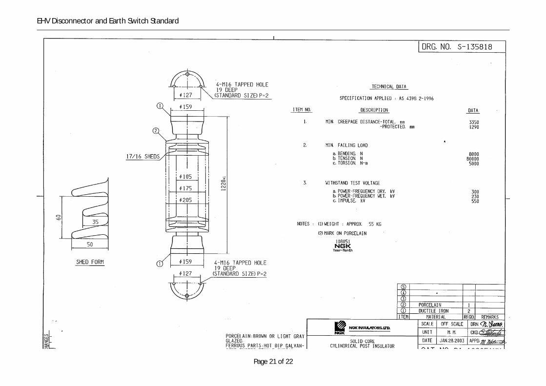
NGK 110 kV Post Insulator (Cat. No. DA-108051MM) NGK drawing S-135818
NGK 220 kV Post Insulator (Cat. No. 8A-108101MM) NGK drawing S-135819
2 Service conditionsService conditions shall not exceed the limits stated in AS/NZS 62271.1 Clause 2, together with theparticulars of the system stated in Table 1 of this standard.
Specific environmental conditions for particular works will be stated in the project specifications.
3 Design requirementsAll disconnectors and earth switches must comply with the requirements within Table 1 of this standard, therequirements detailed in AS 62271-102 and other applicable Australian and International Standards. Where aconflict exists, the most onerous requirement shall apply.
Any specific design, installation, operation and maintenance criteria for particular works will be stated in theproject specifications, such as physical mounting arrangement (side-to-side or end-to-end), operatingmechanism (motorised or manual) or with/without integral earth switch.
Table 1 Parameters for disconnectors

Page 9 of 22
EHV Disconnector and Earth Switch Standard
Sr. No. Parameter Unit Value
1. Nominal system voltage (Vn) kV 110 220
2. Highest voltage kV 123 245
3. Power frequency withstand voltage(PFWV)
kVrms 230 460
4. Lightning impulse withstand voltage (LIWV) kVpeak 550 1050
5. Normal voltage variation (criteria forequipment design)
%Vn ±10
6. Frequency Hz 50
7. Normal operating frequency excursionband
Hz 48.8 to 52
8. Power system frequency range Hz 44.5 to 52
9. Normal combined voltage and frequencyvariation (criteria for equipment design)
% ± 10
10. Number of phases - 3
11. Minimum ambient air temperature °C minus 10ParticularsParticularsParticularsParticulars ofofofof disconnectordisconnectordisconnectordisconnector and and and and earth earth earth earthswitchswitchswitchswitch
12. Number of poles (mechanically coupled) - 3
13. Installation - Outdoor
14. Insulation medium - Air
15. Rated short-time withstand current kA 40
16. Rated peak withstand current kA 108
17. Rated short-time s 1
18. Rated current, continuous A 2000 3150
19. Primary terminal palm type (AS 62271-301) 8 9
20. Rated bus-transfer current (AS 62271-102) A 1600 1600
21. Rated induced current switching class - A (AS 62271-102)
22. Mechanical endurance class (disconnector) - M1 (AS 62271-102)
23. Electrical endurance class (earth switch) - E0 (AS 62271-102)
24. Neutral earthing - solidly earthed
25. Rated supply voltage of heater circuit Vac 240
26. Rated supply voltage of auxiliary (motor),indication and interlocking circuits
Vdc 125
27. Rated supply voltage range of auxiliary(motor), indication and interlocking circuits
Vdc 87.5 Vdc – 137.5 Vdc
28. Contact rating of auxiliary switches at 125 Vdc
A 4
29. Degree of protection by enclosure IP 54
Page 10 of 22
EHV Disconnector and Earth Switch Standard
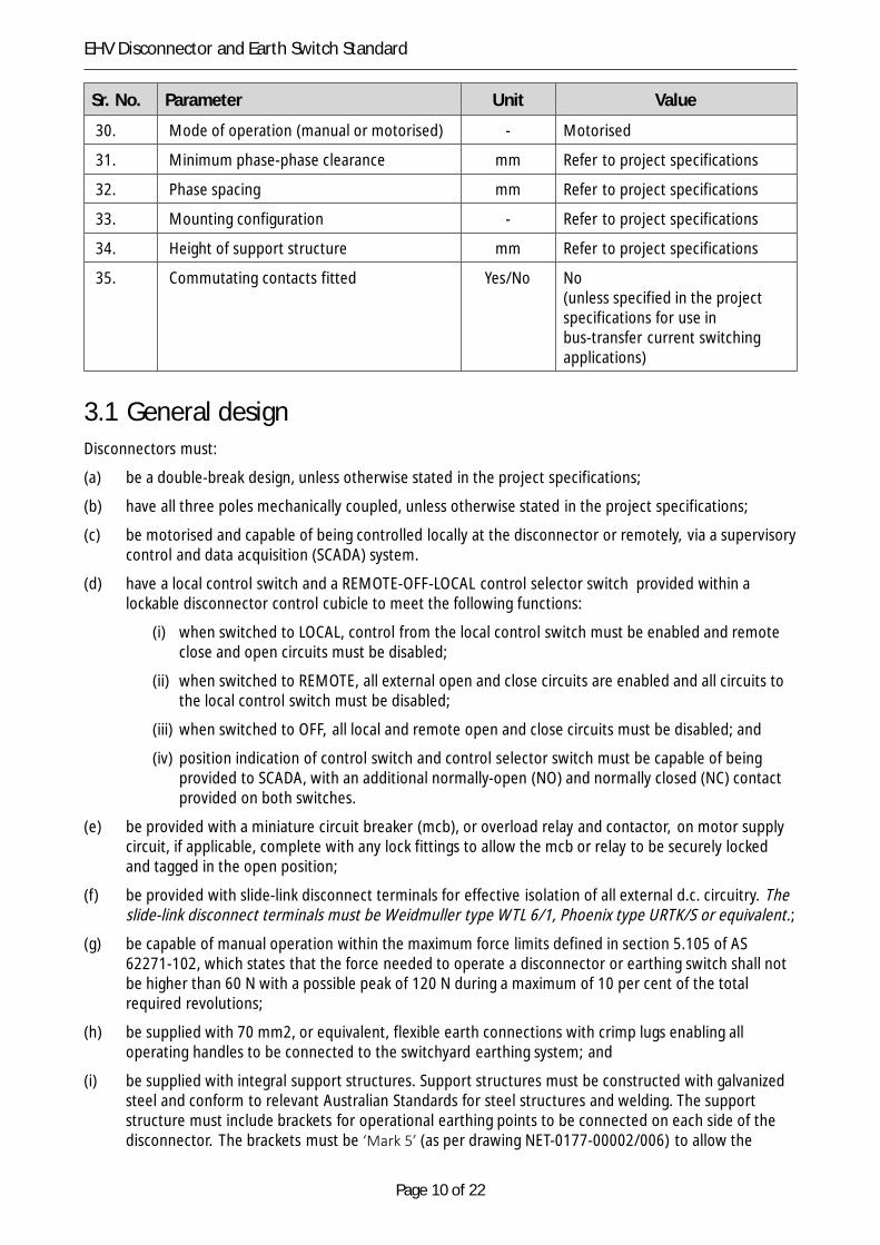
Sr. No. Parameter Unit Value
30. Mode of operation (manual or motorised) - Motorised
31. Minimum phase-phase clearance mm Refer to project specifications
32. Phase spacing mm Refer to project specifications
33. Mounting configuration - Refer to project specifications
34. Height of support structure mm Refer to project specifications
35. Commutating contacts fitted Yes/No No(unless specified in the projectspecifications for use inbus-transfer current switchingapplications)
3.1 General designDisconnectors must:
(a) be a double-break design, unless otherwise stated in the project specifications;
(b) have all three poles mechanically coupled, unless otherwise stated in the project specifications;
(c) be motorised and capable of being controlled locally at the disconnector or remotely, via a supervisorycontrol and data acquisition (SCADA) system.
(d) have a local control switch and a REMOTE-OFF-LOCAL control selector switch provided within alockable disconnector control cubicle to meet the following functions:
(i) when switched to LOCAL, control from the local control switch must be enabled and remoteclose and open circuits must be disabled;
(ii) when switched to REMOTE, all external open and close circuits are enabled and all circuits tothe local control switch must be disabled;
(iii) when switched to OFF, all local and remote open and close circuits must be disabled; and
(iv) position indication of control switch and control selector switch must be capable of beingprovided to SCADA, with an additional normally-open (NO) and normally closed (NC) contactprovided on both switches.
(e) be provided with a miniature circuit breaker (mcb), or overload relay and contactor, on motor supplycircuit, if applicable, complete with any lock fittings to allow the mcb or relay to be securely lockedand tagged in the open position;
(f) be provided with slide-link disconnect terminals for effective isolation of all external d.c. circuitry. Theslide-link disconnect terminals must be Weidmuller type WTL 6/1, Phoenix type URTK/S or equivalent.;
(g) be capable of manual operation within the maximum force limits defined in section 5.105 of AS62271-102, which states that the force needed to operate a disconnector or earthing switch shall notbe higher than 60 N with a possible peak of 120 N during a maximum of 10 per cent of the totalrequired revolutions;
(h) be supplied with 70 mm2, or equivalent, flexible earth connections with crimp lugs enabling alloperating handles to be connected to the switchyard earthing system; and
(i) be supplied with integral support structures. Support structures must be constructed with galvanizedsteel and conform to relevant Australian Standards for steel structures and welding. The supportstructure must include brackets for operational earthing points to be connected on each side of thedisconnector. The brackets must be ‘Mark 5’ (as per drawing NET-0177-00002/006) to allow the

Page 11 of 22
EHV Disconnector and Earth Switch Standard
purchaser to install ‘Type 10’ operation earthing connection points, as detailed inNET-0177-00002/003.
3.1 Earthing switchesWhere stated in the project specifications, disconnectors must be supplied equipped with integral earthingswitches. A free-standing earth switch may also be specified. Earthing switches must:
(a) conform to the requirements detailed in AS 62271-102 for ‘normal service conditions’;
(b) have a short-circuit current withstand capability equivalent to the rated short-time withstand currentcapacity of the associated disconnector;
(c) have earthing switch blades that allow connection of a copper conductor for direct bonding to thesubstation earthing system;
(d) be designed such that the earth switch arms cannot not swing from an open to a closed position, or aclosed to an open position, in the event of a failure of the operating mechanism.
(e) have a lockable operating handle 1200 mm above ground level. The earth switch must not require amanual static effort of more than 250 N to operate the operating handle. A peak value of 450 N isacceptable during the initial 15° rotation;
(f) be supplied with 70 mm2, or equivalent, flexible earth connections with crimp lugs enabling alloperating handles to be connected to the switchyard earthing system; and
(g) be supplied with a visible, corrosion proof, 300 mm x 200 mm flag securely fitted to the top half ofeach of the earth switch arms, comprising 50 mm diagonal black stripes on a yellow background,similar to Figure 1.
Figure 1 Earth switch flag

Page 12 of 22
EHV Disconnector and Earth Switch Standard
3.1 Interlocking requirements(a) The disconnector mechanism must include a solenoid interlock to allow electrical interlocking with its
associated circuit breaker/s to prevent making or breaking of load. An energising pushbutton must beprovided for manual operation.
(b) A free standing earth switch must include a solenoid interlock to allow electrical interlocking with itsassociated disconnectors or enclosure access gates. An energising pushbutton must be provided formanual operation.
(c) The disconnector or earth switch (where fitted) must be capable of being padlocked in both the openand closed positions.
(d) The disconnector must be mechanically interlocked with its integral earthing switch (where fitted)such that the:
(i) earth switch can only be closed when all poles of the disconnector are open; and
(ii) disconnector can only be closed when all poles of the earth switch are open.
(e) The disconnector must be electrically interlocked with its integral earthing switch (where fitted) suchthat the disconnector can only be closed, in either local or remote mode, when all poles of the earthswitch are open.
3.1 Post insulatorsThe project specifications will state if post insulators are to be provided by the supplier or by the purchaser.
(a) If the disconnector supplier is to provide post insulators, the light-grey glazed porcelain insulatorsmust conform to document Extra High Voltage Post Insulators Standard, R574184
(b) If the purchaser is to supply the post insulators, then the disconnectors must be designed to allow theuse of the following post insulators:
(i) for 220 kV disconnectors, NGK Post Insulators Cat. No. 8A-108101MM (see attached NGKdrawing number S-135819); or
(ii) for 110 kV disconnectors, NGK Post Insulators Cat. No. DA-108051MM (see attached NGKdrawing number S-135818).
3.1 Primary line terminalsDisconnector must be provided with:
(a) aluminium primary terminals of a type as listed in Table 1 of this specification, with horizontalorientation, to AS 62271-301; and
(b) primary terminals that have minimum mechanical terminal load ratings as defined in table 3 of AS62271-102.
3.1 Auxiliary switchesDisconnectors and earthing switches must be fitted with an auxiliary switch to provide indication andinterlocking functions. It must be possible to fit additional switches to the disconnector and earthing switch ifrequired. The auxiliary switch must:
(a) comply with the requirements of Clause 5.4 of AS/NZS 62271.1;
(b) be simple and robust, capable of easy adjustment at site, readily accessible and capable of maintainingtheir adjustment for long periods. All springs must be rust proof;

Page 13 of 22
EHV Disconnector and Earth Switch Standard
(c) for disconnectors, have available for external wiring at least eight (8) spare normally-open (NO)contacts and eight (8) spare normally-closed (NC) contacts; and
(d) for earth switches, have available for external wiring at least four (4) spare normally-open (NO)contacts and four (4) spare normally-closed (NC) contacts;
(e) be capable of a contact arrangement of make-before-break; and
(f) be suitably insulated to prevent tracking and moisture absorption.
3.1 Local control and operating cubiclesLocal control and operating cubicles must:
(a) be of a lockable type, constructed from high quality stainless steel (minimum grade 304) or Aluminiumsheet metal panels of sufficient thickness and bracing to provide torsional rigidity;
(b) have doors and covers providing ready access to all operating components for inspection andmaintenance purposes. Door(s) must open to an angle of 120 degrees, and have stays fitted toprevent free swing;
(c) be weather, vermin and dust proof and must have provisions to avoid formation of water pools;
(d) have a minimum degree of protection to IP 54;
(e) have a removable gland plate at the bottom of the cubicle to allow entry of all cables. The gland platemust be a minimum of 2 mm thick and suitable for drilling on site;
(f) have thermostatically controlled space heaters with cut-off control switches to prevent moisturecondensation. The heaters and thermostats must be:
(i) suitable for single phase 230 V, 50 Hz AC system operation;
(ii) rated to withstand temperatures of 100 °C;
(iii) capable of continuous service for the entire life of the unit;
(iv) easily accessible and easily replaceable; and
(v) supplied with appropriate settings and a recommended settings sheet for each installedheater and thermostat combination.
4 Other requirements
4.1 General constructionAll equipment associated with the disconnector assembly must be designed to avoid pockets in which watercan collect.
4.2 Earthing(a) Frames of all equipment supplied must be provided with reliable earth connection points and comply
with relevant Australian Standards.
(b) All connections to earth must comply with requirements of AS/NZS 3000 and be designed to provide afirm connection for the entire life of the equipment.
(c) Disconnectors must be supplied with operator earth mats, as per drawing TasNetworks’ SubstationStandard Outdoor Switchyard Operator Earthmat Assembly and Details Drawing,

Page 14 of 22
EHV Disconnector and Earth Switch Standard
TSD-SD-809-0002-004 (note: the purchaser will arrange connection from the operator earth mat tothe switchyard earthing system).
(d) Earthing terminals must be suitable for connecting copper earthing strip size 40 mm x 6 mm using as aminimum 2 x 12 mm bolts with 40 mm centres.
4.1 Special toolsAny special tools required for the operation or maintenance of the disconnector and earth switch (wherefitted) must be provided.
4.2 Documentation requirements(a) Dimensional plan and section drawings for the disconnector and earth switch and any associated
accessories must be produced and submitted for approval by TasNetworks . The drawings must showthe final outline dimensions, total mass, details of insulator, primary and earth terminals, supportstructure attachment points, lifting lugs, operating rods and adjustments, other fittings andaccessories, and the materials utilised.
(b) Separate rating and nameplate drawings must be produced and submitted for approval byTasNetworks .
(c) Separate schematic and wiring diagrams, with label details must be produced and submitted forapproval by TasNetworks .
(d) Details on packaging and handling the equipment during transport and erection must be provided andsubmitted for approval by TasNetworks .
(e) Operation and maintenance manual must be provided and submitted for approval by TasNetworks .
(f) Separate construction drawings must show the mounting structures and all detail required to installthe equipment, including minimum clearances in air (between poles and to earth), isolating distances,rated static and dynamic mechanical terminal loads.
(g) All documents and drawings must be clear, legible and free from errors or omissions.
(h) All documents and drawings must be in the English language ONLY.
(i) Only SI system of units can be used. Units must be stated for all values.
(j) Scales, where used, must be as per the applicable Australian Standards.
(k) All drawings that are made to scale must include a scale block.
(l) Electronic copies of drawings must be supplied on CD-rom in the AutoCad Release 14 format.
(m) Only information relevant to the supplied disconnector and earth switch, if fitted, must be shown inthe documentation and drawings.
4.1 Nameplates(a) The disconnectors must be provided with nameplates that are:
(i) legible and in the English language;
• permanently and indelibly marked;
• securely fixed in position;
• weather proof and corrosion-proof;
• made of stainless steel or a material of equal durability; and

Page 15 of 22
EHV Disconnector and Earth Switch Standard
• readable from ground level.
(b) In addition to the actual device ratings and detailed requirements of Table 4 of AS 62271-102, thefollowing information must be included on the disconnector nameplate:
(i) Purchaser: Tasmanian Networks Pty Ltd; and
(ii) Purchaser’s Contract Number: refer to project specifications.
5 Testing(a) All components of the disconnector and earthing switch (where fitted) must be duly tested in
accordance with applicable Australian and International standards. Where tests are optional in thestandards, it will be considered that these tests are required by TasNetworks , unless otherwiserequested by Contractor and agreed in writing by TasNetworks before the award of Contract.
(b) All test reports must be forwarded to TasNetworks for approval and acceptance. The tests will beconsidered as completed only after approval and acceptance of test results by TasNetworks in writing.A list of the tests to be conducted on disconnectors and earthing switches (where fitted) is givenbelow.
5.1 Type tests(a) Type tests are intended to prove the soundness of design of the disconnector and earthing switch
(where fitted) and its suitability for operation under the conditions detailed in the projectspecifications. Type tests must be carried out before delivery. A certified test report, detailing theresults of such tests along with the procedures followed, must be provided to TasNetworks . Thesetests must have been applied to a disconnector and earthing switch (where fitted) of identical designto that offered, or on a design which does not differ from that offered in any way which mightinfluence the properties to be confirmed by the type test.
(b) Where such tests have already been performed, a copy of the type test reports that qualifies for theexemption from conducting these tests must be provided with the tender.
(c) Type tests for each type of disconnector and earth switch must be performed to relevant Australianand International Standards and must include all mandatory and optional type tests. Where type testsdiffer from the requirements under the relevant Australian and International Standards, theContractor/Supplier must detail and submit a list of non-conformances to TasNetworks forconsideration.
5.1 Routine tests(a) Routine tests must be conducted on the complete system to prove quality of manufacture and
conformance with the relevant performance requirements of the applicable standards. Splitting ofroutine tests into separate stages for individual components of the system is not acceptable. Routinetesting must be performed at the manufacturer’s works prior to delivery.
(b) Procedures for routine tests and supporting documentation must be submitted to TasNetworks forapproval and acceptance. Routine tests must not be conducted unless the routine test procedureshave been accepted and approved by TasNetworks .
(c) Routine tests for each disconnector and earth switch must be performed to relevant Australian andInternational Standards, and must include a control wire check. Where routine tests differ from therequirements under the relevant Australian and International Standards, the Contractor/Supplier mustdetail and submit a list of non-conformances to TasNetworks for consideration.

Page 16 of 22
EHV Disconnector and Earth Switch Standard
6 Packaging(a) The supplier is responsible for ensuring adequate packaging is provided to minimize the risk of
damage to equipment during delivery. The packaging must be suited to the particular methods ofdelivery and provide protection against damage from all foreseen hazards.
(b) Details of packaging methods must be submitted to TasNetworks for review.
7 Data for asset management information system(a) TasNetworks maintains a comprehensive ‘Asset Management Information System’ (AMIS) that
contains all design, test results and the condition of all TasNetworks assets. The AMIS also containsmaintenance regimes for all assets.
(b) The supplier must provide the information required to maintain the currency of AMIS for each asset instandard forms. TasNetworks will provide the forms to the selected supplier. Forms are required to befilled in for all new assets.
8 Maintenance procedures and plans(a) Detailed maintenance procedures covering the entire life of the disconnector and earth switch must
be provided, including installation, commissioning, maintenance and decommissioning procedures.
(b) Adjustment procedures and diagrams must be provided.
(c) Blank inspection and test plans for commissioning, maintenance and routine testing, for use byTasNetworks maintenance personnel, must be provided.
9 Information to be provided with tenderRequirements for information to be submitted as part of the tender are outlined in document R5864915.
10DeliverablesRequirements for disconnector and earth switch deliverables are outlined in document R586491.
11Hold pointsThe hold points for disconnector and earth switch include:
(a) ‘Critical design information documentation’ must be submitted 4 weeks after receipt of letter ofacceptance for TasNetworks’ review, comments and approval prior to procurement of equipment.
(b) ‘Detailed design documentation’ must be submitted prior to manufacturing of equipment, forTasNetworks’ review, comment and approval.
(c) ‘Inspection and Test Plan’ must be submitted three months prior to any testing of equipment, forTasNetworks’ review, comment and approval.
(d) ‘Invitation to witness testing’ must be submitted two weeks prior to any testing of equipment.
Page 17 of 22
EHV Disconnector and Earth Switch Standard
(e) Complete updated design documentation and operations and maintenance manuals must besubmitted one week prior to ‘Factory Acceptance Testing (FAT)’ for TasNetworks’ preparation toattend FAT, if required.
(f) Final training manuals must be provided at least two weeks prior to delivery of the EHV disconnectorand earth switch, for use by the training team.
(g) FAT results must be submitted to TasNetworks for approval with any non-conformances identified andrectified prior to shipment.
(h) All as-built documentation, operation and maintenance manuals, test results and test certificates mustbe submitted to TasNetworks and be accepted by TasNetworks prior to acceptance of equipment.
(i) Information for AMIS pertaining to design information, test results and maintenance regimes must besubmitted to TasNetworks prior to acceptance of equipment.
(j) Certificate of conformance must be submitted to TasNetworks prior to acceptance of equipment.
(k) Inspection of each EHV disconnector and earth switch (where fitted) after delivery is required byTasNetworks prior to acceptance of equipment. The supplier is required to witness inspections ofequipment after delivery to TasNetworks . The supplier may elect to appoint its representative toattend inspections after delivery.
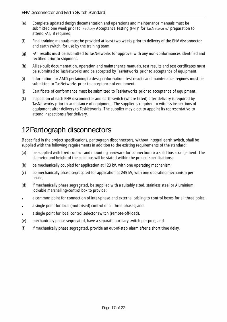
12Pantograph disconnectorsIf specified in the project specifications, pantograph disconnectors, without integral earth switch, shall besupplied with the following requirements in addition to the existing requirements of the standard:
(a) be supplied with fixed contact and mounting hardware for connection to a solid bus arrangement. Thediameter and height of the solid bus will be stated within the project specifications;
(b) be mechanically coupled for application at 123 kV, with one operating mechanism;
(c) be mechanically phase segregated for application at 245 kV, with one operating mechanism perphase;
(d) if mechanically phase segregated, be supplied with a suitably sized, stainless steel or Aluminium,lockable marshalling/control box to provide:
• a common point for connection of inter-phase and external cabling to control boxes for all three poles;
• a single point for local (motorised) control of all three phases; and
• a single point for local control selector switch (remote-off-load).
(e) mechanically phase segregated, have a separate auxiliary switch per pole; and
(f) if mechanically phase segregated, provide an out-of-step alarm after a short time delay.

Page 18 of 22
EHV Disconnector and Earth Switch Standard

Page 19 of 22
EHV Disconnector and Earth Switch Standard

Page 20 of 22
EHV Disconnector and Earth Switch Standard
Page 21 of 22
EHV Disconnector and Earth Switch Standard

Page 22 of 22
EHV Disconnector and Earth Switch Standard

Page 23 of 22
EHV Disconnector and Earth Switch Standard