Embed Size (px)
Citation preview
12 Clintonville RoadNorthford, CT 06472TEL (203) 484-7161
FAX 203.484.7718
EIA-232D Protocol AndData Formats for the AFP-200
Fire Alarm Control Panel
ADOCUMENT # 5007805/18/94 REV:
P/N 50078:A ECN 94-143
www.PDF-Zoo.com
DOCUMENT 50078 REV. A 05/18/942
Table of Contents
Section 1.0 Introduction ........................................................... Page 3
Section 2.0 Protocol .................................................................. Page 3
Section 3.0 Interface Connections ........................................... Page 3
Section 4.0 Input Characters .................................................... Page 3 Section 4.1 Special Function Keys ............................................................... Page 3
Section 5.0 Output Characters ................................................. Page 4 Section 5.1 Printer Characters ..................................................................... Page 4 Section 5.2 Message Terminator ................................................................. Page 4
Section 6.0 Modes of Operation ............................................... Page 5 Section 6.1 Local Terminal Mode ................................................................. Page 5 Section 6.2 Local Monitor Mode ................................................................... Page 5 Section 6.3 Remote Monitor Mode ............................................................... Page 5
Section 7.0 Message Formats and Descriptions .................... Page 6 Section 7.1 Alarm Messages........................................................................ Page 6 Section 7.2 Point Trouble Messages ............................................................ Page 7 Section 7.3 Normal Messages (Addressable Detectors) .............................. Page 8 Section 7.4 Normal Messages (Addressable Modules) ................................ Page 8 Section 7.5 Pre-Alarm Messages ................................................................. Page 9 Section 7.6 Pre-Alarm Clear Messages ....................................................... Page 9 Section 7.7 System Trouble Messages ...................................................... Page 10
Section 8.0 Read Status.......................................................... Page 11 Section 8.1 Point Read ............................................................................... Page 11 Section 8.2 Alarm and Trouble Status ........................................................ Page 11 Section 8.3 Read All Points ........................................................................ Page 11 Section 8.4 Read History - Step ................................................................. Page 12 Section 8.5 Read History - All .................................................................... Page 12
Section 9.0 Status Change ..................................................... Page 12 Section 9.1 Disable/Enable ........................................................................ Page 12 Section 9.2 Detector Sensitivity .................................................................. Page 13 Section 9.3 Clear Verification Counters ..................................................... Page 13 Section 9.4 Clear History Buffer ................................................................. Page 13 Section 9.5 Action and Alert Levels ............................................................ Page 14
Section 10.0 System Commands ........................................... Page 14 Section 10.1 Acknowledge ......................................................................... Page 14 Section 10.2 Signal Silence ........................................................................ Page 14 Section 10.3 System Reset ........................................................................ Page 15 Section 10.4 Manual Evacuate ................................................................... Page 15
Appendix A: AFP-200 Type Codes......................................... Page 16
Appendix B: AFP-200 Status Banners................................... Page 17
Appendix C: European Mode ................................................. Page 18
www.PDF-Zoo.com
3DOCUMENT 50078 REV. A 05/18/94
1.0 IntroductionThis document defines the protocol and data formats that the Notifier AFP-200 Fire Alarm Control Panel uses tocommunicate information over the EIA-232D serial interface.
2.0 ProtocolThe AFP-200 FACP protocol is as follows:
- serial communications- 2400 BAUD- full duplex- 1 start bit- 7 data bits- 1 parity bit- even parity- 1 stop bit
3.0 Interface ConnectionsThe serial interface used to connect the AFP-200 to external devices (terminals, monitors and printers) is located onthe AFP-200 motherboard terminal block TB4 and is as follows:
AFP-200 TB4 Function DB-25 ConnectorTerminal 1 Transmit Pin 3Terminal 2 Reference Pin 7Terminal 3 Receive Pin 2
4.0 Input CharactersThe following sections describe the valid data characters the AFP-200 FACP will process, all other input characterswill be ignored.
The general input characters are as follows:
Characters Hexadecimal CodesA - Z 41 - 5Aa - z 61 - 7A0 - 9 30 - 39Space 20( 28) 29- 2D. 2EBack Space 08Carriage Return 0D~ 7E
4.1 Special Function KeysThe following list defines the character codes the AFP-200 FACP will look for when a special function key isdepressed. These keys must be programmed as defined for proper special function key operation.
Key Function Code F1 Read Status ~A F2 Alter Status ~B F5 Prior ~E F6 Next ~F F12 Acknowledge ~L F13 Signal Silence ~M F14 System Reset ~N
Shift F13 Manual Evacuate ~Q
www.PDF-Zoo.com
DOCUMENT 50078 REV. A 05/18/944
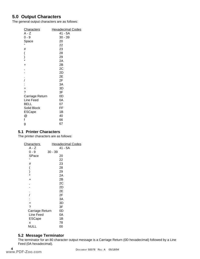
5.0 Output CharactersThe general output characters are as follows:
Characters Hexadecimal CodesA - Z 41 - 5A0 - 9 30 - 39Space 20" 22# 23( 28) 29* 2A+ 2B, 2C- 2D. 2E/ 2F: 3A= 3D? 3FCarriage Return 0DLine Feed 0ABELL 07Solid Block FFESCape 1B@ 40f 66g 67
5.1 Printer CharactersThe printer characters are as follows:
Characters Hexadecimal Codes A - Z 41 - 5A 0 - 9 30 - 39 SPace 20 " 22 # 23 ( 28 ) 29 * 2A + 2B , 2C - 2D . 2E / 2F : 3A = 3D ? 3F Carriage Return 0D Line Feed 0A ESCape 1B x 78 NULL 00
5.2 Message TerminatorThe terminator for an 80 character output message is a Carriage Return (0D hexadecimal) followed by a LineFeed (0A hexadecimal).
www.PDF-Zoo.com
5DOCUMENT 50078 REV. A 05/18/94
6.0 Modes of OperationThe AFP-200 FACP may communicate with a remote terminal, computer or printer connected to its EIA-232 serialport. The EIA-232 port can be configured for interactive operation or for monitoring only. Interactive operationrequires that all equipment be UL listed under UL Standard for Safety UL864 and be installed/configured as directedunder "Local Terminal Mode (LocT)" or "Local Monitor Mode (LocM)." Electronic Data Processing (EDP) listedequipment is permitted for ancillary system monitoring when the system is installed/configured as directed under"Remote Monitor Mode (RemM)."Note: The use of EDP listed equipment is also permitted for temporary applications such as system servicing orprogramming.
The EIA-232 ports on some terminals/computers, including the Notifier CRT-2, are not isolated from earth ground.These devices should be connected to the AFP-200 via isolation modems only, since their direct connection wouldresult in a ground fault being introduced on the AFP-200.
There are three different operating modes for the EIA-232 port, Local Terminal, Local Monitor, and Remote Monitor.The operating mode is selected during panel programming, under the system parameters section (7=SYSTEM). Theoperation of each mode is described in the following section.
6.1 Local Terminal Mode (LocT)Local Terminal Mode operation allows the user to perform Read Status and Alter Status operations from theterminal. In addition the user can also Acknowledge, Signal Silence, Reset, and perform a Drill function from theterminal. A user definable password is required to perform the Alter Status function. The following functions areavailable when operating in Local Terminal Mode:Note: The Terminal must be mounted in a UL-864 listed enclosure, a Notifier Rack-51, Rack-67 or arranged toprovide equivalent protection against unauthorized use.
Read StatusDisplay the status of an individual point (Detector, Module, Panel Circuit, or Zone)Display a list of all the points in alarm or troubleDisplay a list of all programmed points in the systemStep through the history buffer event by eventDisplay the entire history buffer
Alter StatusDisable/Enable an individual pointChange the sensitivity of a detectorClear the verification counter of all detectorsClear the entire history bufferSet the AWACS alert and action levels
Control FunctionsAcknowledgeSignal SilenceSystem ResetDrill
6.2 Local Monitor Mode (LocM)Local Monitor mode operation allows the same functions as Local Terminal mode with the exception that apassword is required to perform Acknowledge, Silence, Reset, and Drill. Because of this password securityfeature the terminal does not need to be enclosed in a rack to prevent unauthorized use.
6.3 Remote Monitor Mode (RemM)Remote Monitor mode operation only permits the user to perform the Read Status function. This mode can beused with UL EDP listed terminals, including personal computers using Notifier PK-1 release 2.0 software orterminal emulation software. It is also intended for terminals that are connected through modems, including FSKmodems connected through a public switched telephone network.
www.PDF-Zoo.com
DOCUMENT 50078 REV. A 05/18/946
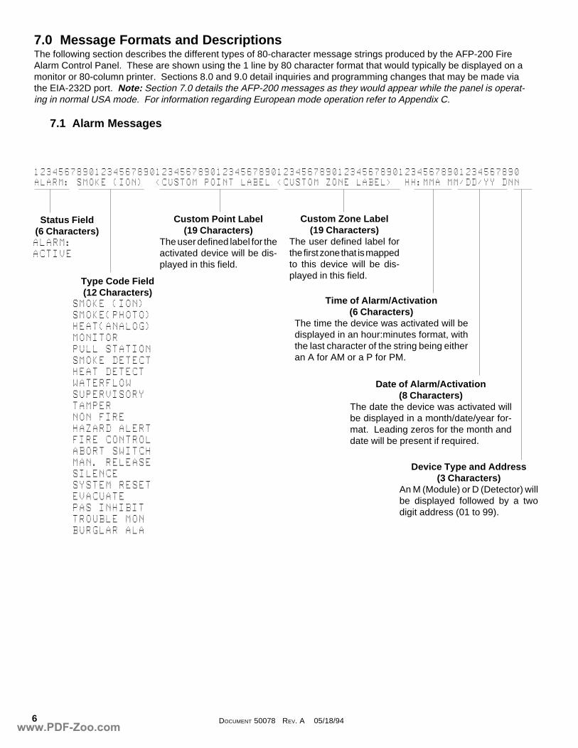
7.0 Message Formats and DescriptionsThe following section describes the different types of 80-character message strings produced by the AFP-200 FireAlarm Control Panel. These are shown using the 1 line by 80 character format that would typically be displayed on amonitor or 80-column printer. Sections 8.0 and 9.0 detail inquiries and programming changes that may be made viathe EIA-232D port. Note: Section 7.0 details the AFP-200 messages as they would appear while the panel is operat-ing in normal USA mode. For information regarding European mode operation refer to Appendix C.
7.1 Alarm Messages
12345678901234567890123456789012345678901234567890123456789012345678901234567890ALARM:@SMOKE@(ION)@@<CUSTOM@POINT@LABEL@<CUSTOM@ZONE@LABEL>@@HH:MMA@MM/DD/YY@DNN
Status Field(6 Characters)ALARM:ACTIVE
Type Code Field(12 Characters)
SMOKE@(ION)SMOKE(PHOTO)HEAT(ANALOG)MONITORPULL@STATIONSMOKE@DETECTHEAT@DETECTWATERFLOWSUPERVISORYTAMPERNON@FIREHAZARD@ALERTFIRE@CONTROLABORT@SWITCHMAN.@RELEASESILENCESYSTEM@RESETEVACUATEPAS@INHIBITTROUBLE@MONBURGLAR@ALA
Custom Zone Label(19 Characters)
The user defined label forthe first zone that is mappedto this device will be dis-played in this field.
Custom Point Label(19 Characters)
The user defined label for theactivated device will be dis-played in this field.
Time of Alarm/Activation(6 Characters)
The time the device was activated will bedisplayed in an hour:minutes format, withthe last character of the string being eitheran A for AM or a P for PM.
Date of Alarm/Activation(8 Characters)
The date the device was activated willbe displayed in a month/date/year for-mat. Leading zeros for the month anddate will be present if required.
Device Type and Address(3 Characters)
An M (Module) or D (Detector) willbe displayed followed by a twodigit address (01 to 99).
www.PDF-Zoo.com
7DOCUMENT 50078 REV. A 05/18/94
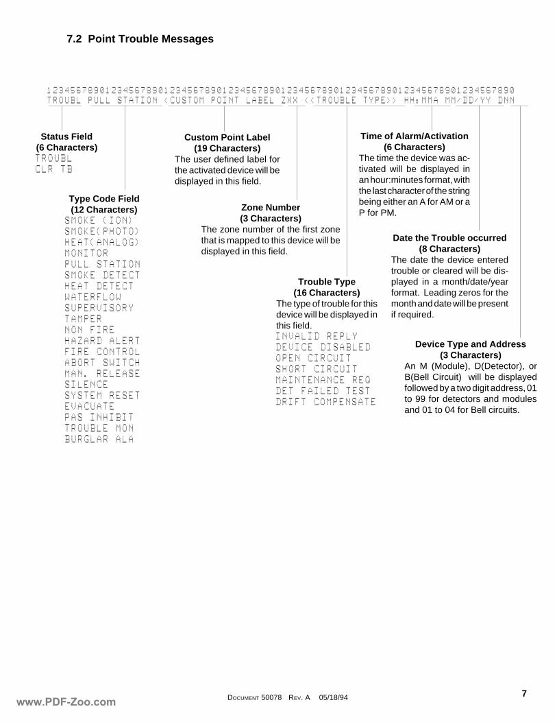
12345678901234567890123456789012345678901234567890123456789012345678901234567890TROUBL@PULL@STATION@<CUSTOM@POINT@LABEL@ZXX@<<TROUBLE@TYPE>>@HH:MMA@MM/DD/YY@DNN
Status Field(6 Characters)TROUBLCLR@TB
Type Code Field(12 Characters)
SMOKE@(ION)SMOKE(PHOTO)HEAT(ANALOG)MONITORPULL@STATIONSMOKE@DETECTHEAT@DETECTWATERFLOWSUPERVISORYTAMPERNON@FIREHAZARD@ALERTFIRE@CONTROLABORT@SWITCHMAN.@RELEASESILENCESYSTEM@RESETEVACUATEPAS@INHIBITTROUBLE@MONBURGLAR@ALA
Custom Point Label(19 Characters)
The user defined label forthe activated device will bedisplayed in this field.
Time of Alarm/Activation(6 Characters)
The time the device was ac-tivated will be displayed inan hour:minutes format, withthe last character of the stringbeing either an A for AM or aP for PM.
Date the Trouble occurred(8 Characters)
The date the device enteredtrouble or cleared will be dis-played in a month/date/yearformat. Leading zeros for themonth and date will be presentif required.
Device Type and Address(3 Characters)
An M (Module), D(Detector), orB(Bell Circuit) will be displayedfollowed by a two digit address, 01to 99 for detectors and modulesand 01 to 04 for Bell circuits.
Trouble Type(16 Characters)
The type of trouble for thisdevice will be displayed inthis field.INVALID@REPLYDEVICE@DISABLEDOPEN@CIRCUITSHORT@CIRCUITMAINTENANCE@REQDET@FAILED@TESTDRIFT@COMPENSATE
Zone Number(3 Characters)
The zone number of the first zonethat is mapped to this device will bedisplayed in this field.
7.2 Point Trouble Messages
www.PDF-Zoo.com
DOCUMENT 50078 REV. A 05/18/948
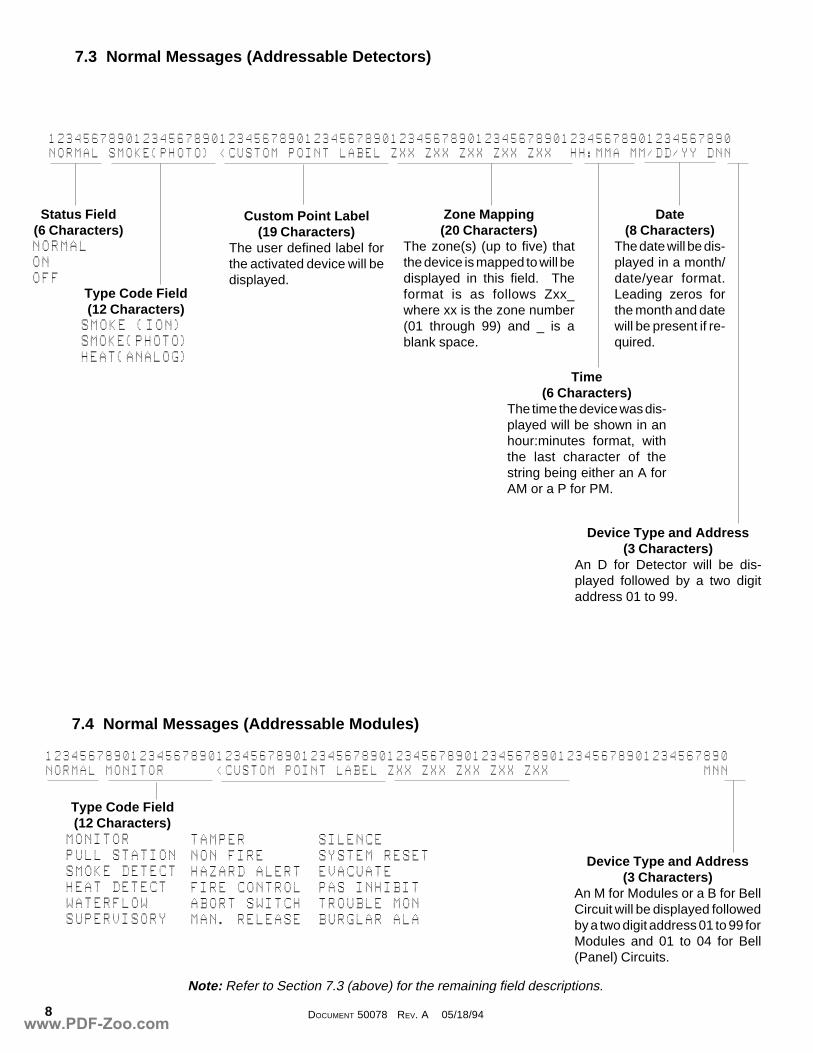
7.3 Normal Messages (Addressable Detectors)
12345678901234567890123456789012345678901234567890123456789012345678901234567890NORMAL@SMOKE(PHOTO)@<CUSTOM@POINT@LABEL@ZXX@ZXX@ZXX@ZXX@ZXX@@HH:MMA@MM/DD/YY@DNN
Type Code Field(12 Characters)SMOKE@(ION)SMOKE(PHOTO)HEAT(ANALOG)
Status Field(6 Characters)NORMALONOFF
Custom Point Label(19 Characters)
The user defined label forthe activated device will bedisplayed.
Zone Mapping(20 Characters)
The zone(s) (up to five) thatthe device is mapped to will bedisplayed in this field. Theformat is as follows Zxx_where xx is the zone number(01 through 99) and _ is ablank space.
Date(8 Characters)
The date will be dis-played in a month/date/year format.Leading zeros forthe month and datewill be present if re-quired.
Device Type and Address(3 Characters)
An D for Detector will be dis-played followed by a two digitaddress 01 to 99.
Time(6 Characters)
The time the device was dis-played will be shown in anhour:minutes format, withthe last character of thestring being either an A forAM or a P for PM.
12345678901234567890123456789012345678901234567890123456789012345678901234567890NORMAL@MONITOR@@@@@@<CUSTOM@POINT@LABEL@ZXX@ZXX@ZXX@ZXX@ZXX@@@@@@@@@@@@@@@@@@MNN
7.4 Normal Messages (Addressable Modules)
Device Type and Address(3 Characters)
An M for Modules or a B for BellCircuit will be displayed followedby a two digit address 01 to 99 forModules and 01 to 04 for Bell(Panel) Circuits.
Note: Refer to Section 7.3 (above) for the remaining field descriptions.
Type Code Field(12 Characters)
MONITORPULL@STATIONSMOKE@DETECTHEAT@DETECTWATERFLOWSUPERVISORY
TAMPERNON@FIREHAZARD@ALERTFIRE@CONTROLABORT@SWITCHMAN.@RELEASE
SILENCESYSTEM@RESETEVACUATEPAS@INHIBITTROUBLE@MONBURGLAR@ALA
www.PDF-Zoo.com
9DOCUMENT 50078 REV. A 05/18/94
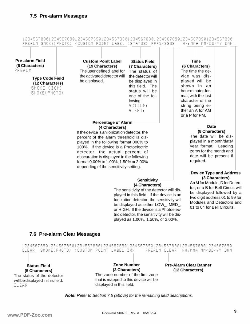
7.5 Pre-alarm Messages
12345678901234567890123456789012345678901234567890123456789012345678901234567890PREALM@SMOKE(PHOTO)@<CUSTOM@POINT@LABEL@<STATUS>@PPP%/SSSS@@@HH:MMA@MM/DD/YY@DNN
Pre-alarm Field(6 Characters)PREALM
Type Code Field(12 Characters)SMOKE@(ION)SMOKE(PHOTO)
Custom Point Label(19 Characters)
The user defined label forthe activated detector willbe displayed.
Status Field(7 Characters)The status ofthe detector willbe displayed inthis field. Thestatus will beone of the fol-lowing:ACTION:ALERT:
Time(6 Characters)
The time the de-vice was dis-played will beshown in anhour:minutes for-mat, with the lastcharacter of thestring being ei-ther an A for AMor a P for PM.
Date(8 Characters)
The date will be dis-played in a month/date/year format. Leadingzeros for the month anddate will be present ifrequired.
Device Type and Address(3 Characters)
An M for Module, D for Detec-tor, or a B for Bell Circuit willbe displayed followed by atwo digit address 01 to 99 forModules and Detectors and01 to 04 for Bell Circuits.
Percentage of Alarm(4 Characters)
If the device is an Ionization detector, thepercent of the alarm threshold is dis-played in the following format 000% to100%. If the device is a Photoelectricdetector, the actual percent ofobscuration is displayed in the followingformat 0.00% to 1.00%, 1.50% or 2.00%depending of the sensitivity setting.
Sensitivity(4 Characters)
The sensitivity of the detector will dis-played in this field. If the device is anIonization detector, the sensitivity willbe displayed as either LOW_, MED_,or HIGH. If the device is a Photoelec-tric detector, the sensitivity will be dis-played as 1.00%, 1.50%, or 2.00%.
7.6 Pre-alarm Clear Messages
12345678901234567890123456789012345678901234567890123456789012345678901234567890CLEAR@@SMOKE(PHOTO)@<CUSTOM@POINT@LABEL@ZXX@@@@PREALM@CLEAR@@HH:MMA@MM/DD/YY@DNN
Status Field(5 Characters)
The status of the detectorwill be displayed in this field.CLEAR
Zone Number(3 Characters)
The zone number of the first zonethat is mapped to this device will bedisplayed in this field.
Pre-Alarm Clear Banner(12 Characters)
Note: Refer to Section 7.5 (above) for the remaining field descriptions.
www.PDF-Zoo.com
DOCUMENT 50078 REV. A 05/18/9410
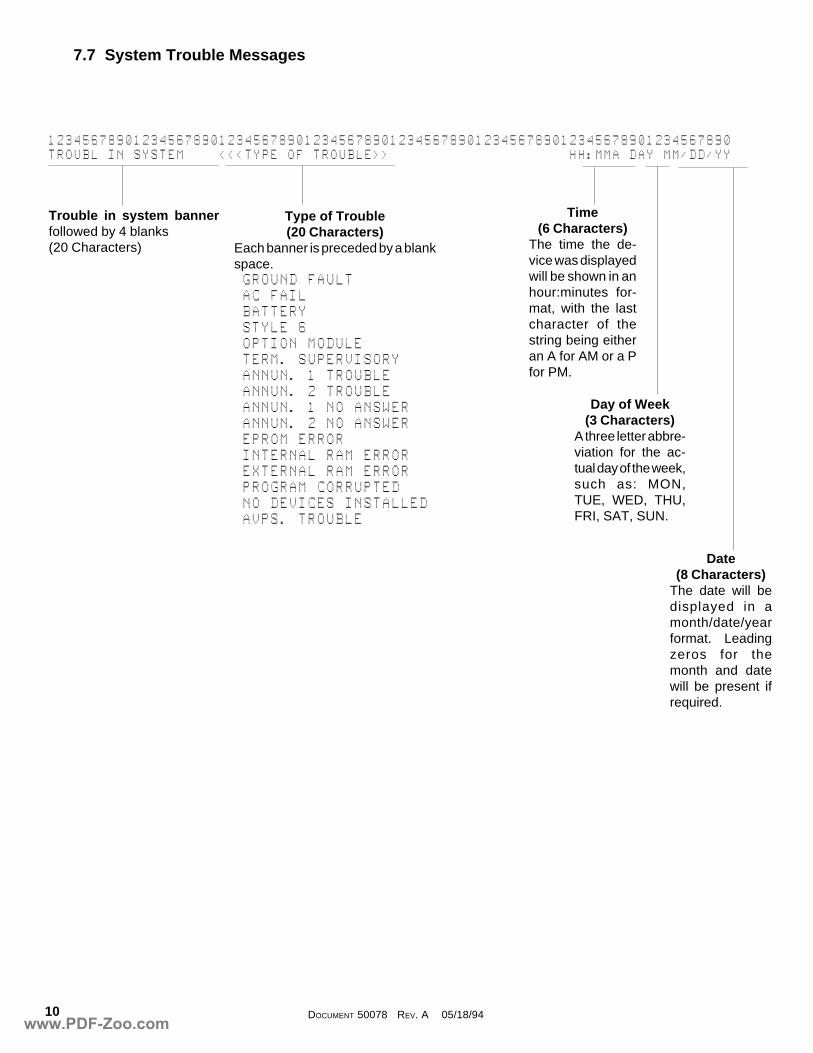
7.7 System Trouble Messages
12345678901234567890123456789012345678901234567890123456789012345678901234567890TROUBL@IN@SYSTEM@@@@<<<TYPE@OF@TROUBLE>>@@@@@@@@@@@@@@@@@@@@@HH:MMA@DAY@MM/DD/YY
Trouble in system bannerfollowed by 4 blanks(20 Characters)
Type of Trouble(20 Characters)
Each banner is preceded by a blankspace.@GROUND@FAULT@AC@FAIL@BATTERY@STYLE@6@OPTION@MODULE@TERM.@SUPERVISORY@ANNUN.@1@TROUBLE@ANNUN.@2@TROUBLE@ANNUN.@1@NO@ANSWER@ANNUN.@2@NO@ANSWER@EPROM@ERROR@INTERNAL@RAM@ERROR@EXTERNAL@RAM@ERROR@PROGRAM@CORRUPTED@NO@DEVICES@INSTALLED@AVPS.@TROUBLE
Time(6 Characters)
The time the de-vice was displayedwill be shown in anhour:minutes for-mat, with the lastcharacter of thestring being eitheran A for AM or a Pfor PM.
Day of Week(3 Characters)
A three letter abbre-viation for the ac-tual day of the week,such as: MON,TUE, WED, THU,FRI, SAT, SUN.
Date(8 Characters)
The date will bedisplayed in amonth/date/yearformat. Leadingzeros for themonth and datewill be present ifrequired.
www.PDF-Zoo.com
11DOCUMENT 50078 REV. A 05/18/94
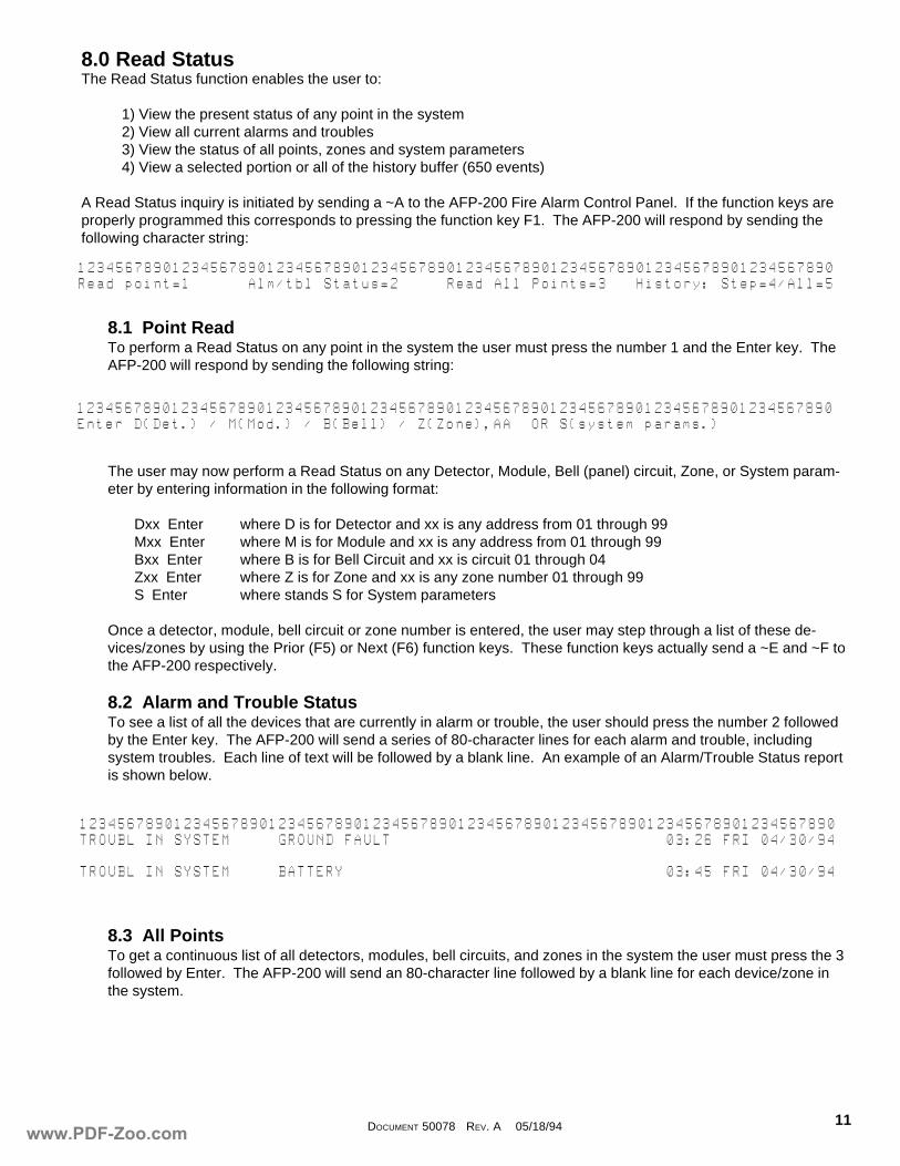
8.0 Read StatusThe Read Status function enables the user to:
1) View the present status of any point in the system2) View all current alarms and troubles3) View the status of all points, zones and system parameters4) View a selected portion or all of the history buffer (650 events)
A Read Status inquiry is initiated by sending a ~A to the AFP-200 Fire Alarm Control Panel. If the function keys areproperly programmed this corresponds to pressing the function key F1. The AFP-200 will respond by sending thefollowing character string:
8.1 Point ReadTo perform a Read Status on any point in the system the user must press the number 1 and the Enter key. TheAFP-200 will respond by sending the following string:
The user may now perform a Read Status on any Detector, Module, Bell (panel) circuit, Zone, or System param-eter by entering information in the following format:
Dxx Enter where D is for Detector and xx is any address from 01 through 99Mxx Enter where M is for Module and xx is any address from 01 through 99Bxx Enter where B is for Bell Circuit and xx is circuit 01 through 04Zxx Enter where Z is for Zone and xx is any zone number 01 through 99S Enter where stands S for System parameters
Once a detector, module, bell circuit or zone number is entered, the user may step through a list of these de-vices/zones by using the Prior (F5) or Next (F6) function keys. These function keys actually send a ~E and ~F tothe AFP-200 respectively.
8.2 Alarm and Trouble StatusTo see a list of all the devices that are currently in alarm or trouble, the user should press the number 2 followedby the Enter key. The AFP-200 will send a series of 80-character lines for each alarm and trouble, includingsystem troubles. Each line of text will be followed by a blank line. An example of an Alarm/Trouble Status reportis shown below.
8.3 All PointsTo get a continuous list of all detectors, modules, bell circuits, and zones in the system the user must press the 3followed by Enter. The AFP-200 will send an 80-character line followed by a blank line for each device/zone inthe system.
12345678901234567890123456789012345678901234567890123456789012345678901234567890Read@point=1@@@@@@Alm/tbl@Status=2@@@@@Read@All@Points=3@@@History:@Step=4/All=5
12345678901234567890123456789012345678901234567890123456789012345678901234567890Enter@D(Det.)@/@M(Mod.)@/@B(Bell)@/@Z(Zone),AA@@OR@S(system@params.)
12345678901234567890123456789012345678901234567890123456789012345678901234567890TROUBL@IN@SYSTEM@@@@@GROUND@FAULT@@@@@@@@@@@@@@@@@@@@@@@@@@@@@03:26@FRI@04/30/94
TROUBL@IN@SYSTEM@@@@@BATTERY@@@@@@@@@@@@@@@@@@@@@@@@@@@@@@@@@@03:45@FRI@04/30/94
www.PDF-Zoo.com
DOCUMENT 50078 REV. A 05/18/9412
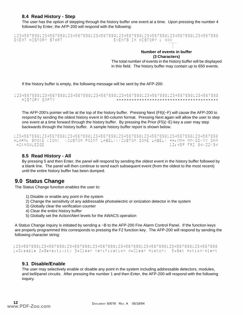
12345678901234567890123456789012345678901234567890123456789012345678901234567890EVENT@HISTORY@START@@@@@@@@@@@@@@@@@@@@EVENTS@IN@HISTORY@:@XXX
12345678901234567890123456789012345678901234567890123456789012345678901234567890@@@HISTORY@EMPTY@@@@@@@@@@@@@@@@@@@@@@@@****************************************
123456789012345678901234567890123456789012345678901234567890123456789012345678901=Disable@2=Sensitivity@3=Clear@Verification@4=Clear@History@@5=Set@Action/Alert
8.4 Read History - StepThe user has the option of stepping through the history buffer one event at a time. Upon pressing the number 4followed by Enter, the AFP-200 will respond with the following:
If the history buffer is empty, the following message will be sent by the AFP-200:
The AFP-200's pointer will be at the top of the history buffer. Pressing Next (F6)(~F) will cause the AFP-200 torespond by sending the oldest history event in 80-column format. Pressing Next again will allow the user to stepone event at a time forward through the history buffer. By pressing the Prior (F5)(~E) key a user may stepbackwards through the history buffer. A sample history buffer report is shown below.
8.5 Read History - AllBy pressing 5 and then Enter, the panel will respond by sending the oldest event in the history buffer followed bya blank line. The panel will then continue to send each subsequent event (from the oldest to the most recent)until the entire history buffer has been dumped.
9.0 Status ChangeThe Status Change function enables the user to:
1) Disable or enable any point in the system2) Change the sensitivity of any addressable photoelectric or ionization detector in the system3) Globally clear the verification counter4) Clear the entire history buffer5) Globally set the Action/Alert levels for the AWACS operation
A Status Change inquiry is initiated by sending a ~B to the AFP-200 Fire Alarm Control Panel. If the function keysare properly programmed this corresponds to pressing the F2 function key. The AFP-200 will respond by sending thefollowing character string:
9.1 Disable/EnableThe user may selectively enable or disable any point in the system including addressable detectors, modules,and bell/panel circuits. After pressing the number 1 and then Enter, the AFP-200 will respond with the followinginquiry.
Number of events in buffer(3 Characters)
The total number of events in the history buffer will be displayedin this field. The history buffer may contain up to 650 events.
12345678901234567890123456789012345678901234567890123456789012345678901234567890ALARM:@SMOKE@(ION)@@<CUSTOM@POINT@LABEL><<CUSTOM@ZONE@LABEL>@HH:MMA@MM/DD/YY@DNN@ACKNOWLEDGE@@@@@@@@@@@@@@@@@@@@@@@@@@@@@@@@@@@@@@@@@@@@@@@@@12:45P@FRI@04/22/94
www.PDF-Zoo.com
13DOCUMENT 50078 REV. A 05/18/94
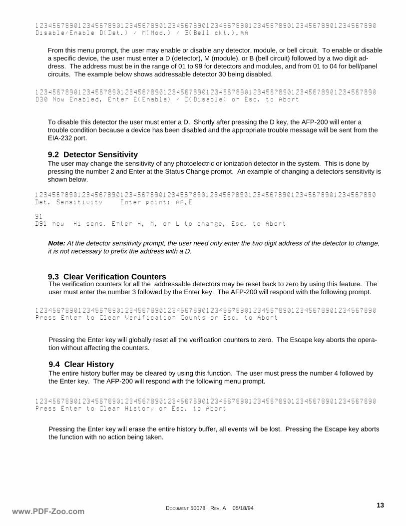
12345678901234567890123456789012345678901234567890123456789012345678901234567890Disable/Enable@D(Det.)@/@M(Mod.)@/@B(Bell@ckt.),AA
From this menu prompt, the user may enable or disable any detector, module, or bell circuit. To enable or disablea specific device, the user must enter a D (detector), M (module), or B (bell circuit) followed by a two digit ad-dress. The address must be in the range of 01 to 99 for detectors and modules, and from 01 to 04 for bell/panelcircuits. The example below shows addressable detector 30 being disabled.
To disable this detector the user must enter a D. Shortly after pressing the D key, the AFP-200 will enter atrouble condition because a device has been disabled and the appropriate trouble message will be sent from theEIA-232 port.
9.2 Detector SensitivityThe user may change the sensitivity of any photoelectric or ionization detector in the system. This is done bypressing the number 2 and Enter at the Status Change prompt. An example of changing a detectors sensitivity isshown below.
Note: At the detector sensitivity prompt, the user need only enter the two digit address of the detector to change,it is not necessary to prefix the address with a D.
12345678901234567890123456789012345678901234567890123456789012345678901234567890D30@Now@Enabled,@Enter@E(Enable)@/@D(Disable)@or@Esc.@to@Abort
9.3 Clear Verification CountersThe verification counters for all the addressable detectors may be reset back to zero by using this feature. Theuser must enter the number 3 followed by the Enter key. The AFP-200 will respond with the following prompt.
Pressing the Enter key will globally reset all the verification counters to zero. The Escape key aborts the opera-tion without affecting the counters.
9.4 Clear HistoryThe entire history buffer may be cleared by using this function. The user must press the number 4 followed bythe Enter key. The AFP-200 will respond with the following menu prompt.
Pressing the Enter key will erase the entire history buffer, all events will be lost. Pressing the Escape key abortsthe function with no action being taken.
12345678901234567890123456789012345678901234567890123456789012345678901234567890Det.@Sensitivity@@@@Enter@point:@AA,E
91D91@now@@Hi@sens.@Enter@H,@M,@or@L@to@change,@Esc.@to@Abort
12345678901234567890123456789012345678901234567890123456789012345678901234567890Press@Enter@to@Clear@Verification@Counts@or@Esc.@to@Abort
12345678901234567890123456789012345678901234567890123456789012345678901234567890Press@Enter@to@Clear@History@or@Esc.@to@Abort
www.PDF-Zoo.com
DOCUMENT 50078 REV. A 05/18/9414
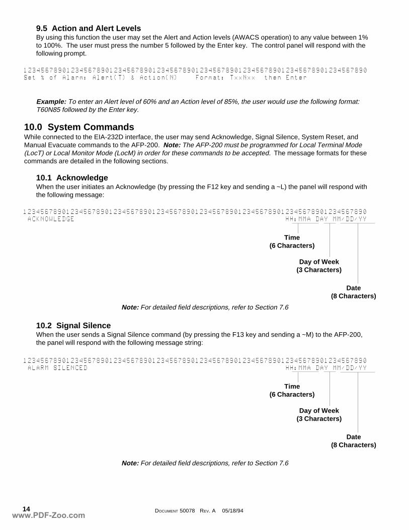
9.5 Action and Alert LevelsBy using this function the user may set the Alert and Action levels (AWACS operation) to any value between 1%to 100%. The user must press the number 5 followed by the Enter key. The control panel will respond with thefollowing prompt.
Example: To enter an Alert level of 60% and an Action level of 85%, the user would use the following format:T60N85 followed by the Enter key.
10.0 System CommandsWhile connected to the EIA-232D interface, the user may send Acknowledge, Signal Silence, System Reset, andManual Evacuate commands to the AFP-200. Note: The AFP-200 must be programmed for Local Terminal Mode(LocT) or Local Monitor Mode (LocM) in order for these commands to be accepted. The message formats for thesecommands are detailed in the following sections.
10.1 AcknowledgeWhen the user initiates an Acknowledge (by pressing the F12 key and sending a ~L) the panel will respond withthe following message:
Note: For detailed field descriptions, refer to Section 7.6
10.2 Signal SilenceWhen the user sends a Signal Silence command (by pressing the F13 key and sending a ~M) to the AFP-200,the panel will respond with the following message string:
Note: For detailed field descriptions, refer to Section 7.6
12345678901234567890123456789012345678901234567890123456789012345678901234567890Set@%@of@Alarm:@Alert(T)@&@Action(N)@@@@Format:@TxxNxx@@then@Enter
12345678901234567890123456789012345678901234567890123456789012345678901234567890@ACKNOWLEDGE@@@@@@@@@@@@@@@@@@@@@@@@@@@@@@@@@@@@@@@@@@@@@@@@@HH:MMA@DAY@MM/DD/YY
Time(6 Characters)
Day of Week(3 Characters)
Date(8 Characters)
12345678901234567890123456789012345678901234567890123456789012345678901234567890@ALARM@SILENCED@@@@@@@@@@@@@@@@@@@@@@@@@@@@@@@@@@@@@@@@@@@@@@HH:MMA@DAY@MM/DD/YY
Time(6 Characters)
Day of Week(3 Characters)
Date(8 Characters)
www.PDF-Zoo.com
15DOCUMENT 50078 REV. A 05/18/94
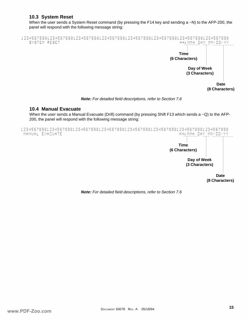
10.3 System ResetWhen the user sends a System Reset command (by pressing the F14 key and sending a ~N) to the AFP-200, thepanel will respond with the following message string:
12345678901234567890123456789012345678901234567890123456789012345678901234567890@@@SYSTEM@RESET@@@@@@@@@@@@@@@@@@@@@@@@@@@@@@@@@@@@@@@@@@@@@@HH:MMA@DAY@MM/DD/YY
Time(6 Characters)
Day of Week(3 Characters)
Date(8 Characters)
Note: For detailed field descriptions, refer to Section 7.6
10.4 Manual EvacuateWhen the user sends a Manual Evacuate (Drill) command (by pressing Shift F13 which sends a ~Q) to the AFP-200, the panel will respond with the following message string:
Note: For detailed field descriptions, refer to Section 7.6
12345678901234567890123456789012345678901234567890123456789012345678901234567890@MANUAL@EVACUATE@@@@@@@@@@@@@@@@@@@@@@@@@@@@@@@@@@@@@@@@@@@@@HH:MMA@DAY@MM/DD/YY
Time(6 Characters)
Day of Week(3 Characters)
Date(8 Characters)
www.PDF-Zoo.com
DOCUMENT 50078 REV. A 05/18/9416
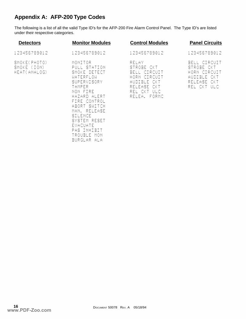
Appendix A: AFP-200 Type Codes
The following is a list of all the valid Type ID's for the AFP-200 Fire Alarm Control Panel. The Type ID's are listedunder their respective categories.
Detectors Monitor Modules Control Modules Panel Circuits
123456789012 123456789012 123456789012 123456789012
SMOKE(PHOTO) MONITOR RELAY BELL@CIRCUITSMOKE@(ION) PULL@STATION STROBE@CKT STROBE@CKTHEAT(ANALOG) SMOKE@DETECT BELL@CIRCUIT HORN@CIRCUIT
WATERFLOW HORN@CIRCUIT AUDIBLE@CKTSUPERVISORY AUDIBLE@CKT RELEASE@CKTTAMPER RELEASE@CKT REL@CKT@ULCNON@FIRE REL@CKT@ULCHAZARD@ALERT RELEA.@FORMCFIRE@CONTROLABORT@SWITCHMAN.@RELEASESILENCESYSTEM@RESETEVACUATEPAS@INHIBITTROUBLE@MONBURGLAR@ALA
www.PDF-Zoo.com
17DOCUMENT 50078 REV. A 05/18/94
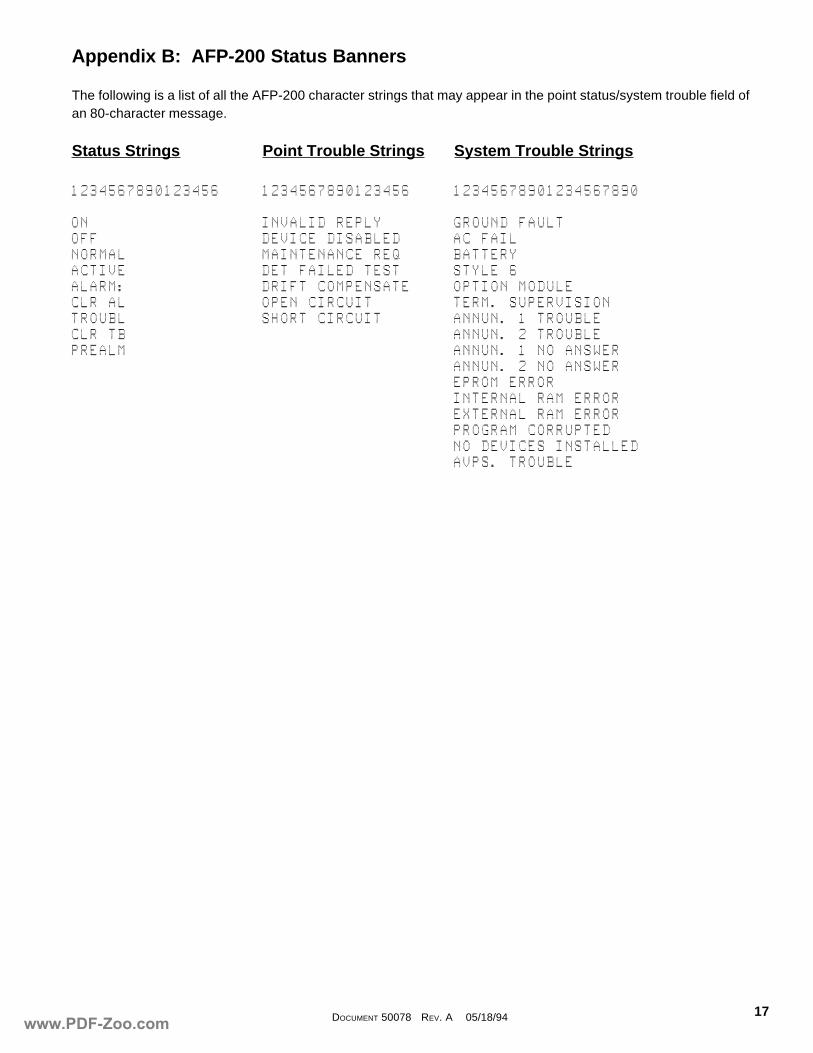
Appendix B: AFP-200 Status Banners
The following is a list of all the AFP-200 character strings that may appear in the point status/system trouble field ofan 80-character message.
Status Strings Point Trouble Strings System Trouble Strings
1234567890123456 1234567890123456 12345678901234567890
ON INVALID@REPLY GROUND@FAULTOFF DEVICE@DISABLED AC@FAILNORMAL MAINTENANCE@REQ BATTERYACTIVE DET@FAILED@TEST STYLE@6ALARM: DRIFT@COMPENSATE OPTION@MODULECLR@AL OPEN@CIRCUIT TERM.@SUPERVISIONTROUBL SHORT@CIRCUIT ANNUN.@1@TROUBLECLR@TB ANNUN.@2@TROUBLEPREALM ANNUN.@1@NO@ANSWER
ANNUN.@2@NO@ANSWEREPROM@ERRORINTERNAL@RAM@ERROREXTERNAL@RAM@ERRORPROGRAM@CORRUPTEDNO@DEVICES@INSTALLEDAVPS.@TROUBLE
www.PDF-Zoo.com

DOCUMENT 50078 REV. A 05/18/9418
Appendix C: European Mode Operation
The AFP-200 Fire Alarm Control Panel may be programmed to operate in European mode. This selection is made inthe system parameters section of programming (refer to the AFP-200 Instruction Manual) by changing the USA TIMEbanner to EUR TIME. Operating the AFP-200 in European mode affects certain 80-character message fields.European mode changes the 12-hour time format to 24-hour (military) time and changes the date display by placingthe day before the month. In USA mode, the date appears in a format of MM:DD:YY. However, in EUR mode, thedate appears in a DD:MM:YY format.
Example: When the panel is operating in European mode, a time of 3:38 PM will be displayed as 15:38and the date November 14, 1994 will be displayed as 14/11/94.
In addition to time/day changes, European mode also affects two status banners in the 80-character messages.When the AFP-200 displays a trouble message, the character string TROUBL is replaced by the string FAULT asshown in the example below.
When a device or zone is disabled, the AFP-200 will display a disable message and the character string DISABLEDwill be replaced by ISOLATED as shown below.
12345678901234567890123456789012345678901234567890123456789012345678901234567890FAULT@@SMOKE(PHOTO)@TECH.@PUBLISHING@@@@Z01@INVALID@REPLY@@@@15:38@@14/11/94@D42
12345678901234567890123456789012345678901234567890123456789012345678901234567890FAULT@@SMOKE(PHOTO)@TECH.@PUBLISHING@@@@Z01@DEVICE@ISOLATED@@15:38@@14/11/94@D42
www.PDF-Zoo.com


![232Dシリーズ - DDK Ltd....232D S 単:mm IUUQ XXX EELOFU DP KQ Õ\w »é¬w 7 sx 'sX !Ëb \qUK bwpz] &M b{y hz L`oM a ¼w QJt| 7x ß pbG a ¼ ;b Mxz7 ýw ò Ö 7 {p º 0w]¬ Ý](https://img.pdfslide.net/doc/110x75/600683a55db144361623a51a/232dff-ddk-ltd-232d-s-imm-iuuq-xxx-eelofu-dp-kq-w-w.jpg)