Embed Size (px)
Citation preview
Confidential
EIEE & Partners GmbH
1
Facility Inspection Report
Propylene Oxide – Polyol – PU Systems Facility
Prepared by:
EIEE & Partners GmbH
Brügglistrasse 7a 8852 Altendorf, SZ, Switzerland
Confidential
EIEE & Partners GmbH
2
Propylene Oxide – Polyol – PU Systems Facility
Executive Summary
• This propylene oxide (PO), polyol, and PU systems facility was closed in 2010 and includes the following plants:
• PO – 20,000 mt/yr: This chlorohydrin based plant includes titanium reactors
and vessels along with two nice propylene storage spheres. There is also a waste water pre-treatment plant incorporated in the PO facility.
• Polyol – 20,000 mt/yr: All of the processing equipment and piping is 304L
stainless steel. This is a small, but nicely designed polyol plant with good technology (Chemetics). There are two completely independent lines; each with two reactors and a dehydration vessel followed by filters. Polyol recipes will be available with the plant.
• Polyurethane (PU) Systems: Two stainless steel “reactors” at 2.0 and 10
cubic meters capacity for preparing PU systems blends of polyol, isocyanate, Freon, etc. Storage tanks are stainless steel and small enough to ship by truck.
• Documentation is available. P&IDs, equipment lists, and original design
manuals along with a few hundred equipment files. Some of this documentation available electronically.
• DCS for automated process control is by Siemens and is available with the
plant.
• There is said to be no asbestos in the facility.
• Transportation to and from the facility is acceptable by rail and road. It is 300 km to the nearest ocean-going port.
Confidential
EIEE & Partners GmbH
3
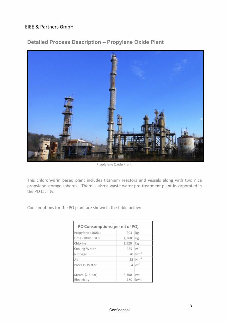
Detailed Process Description – Propylene Oxide Plant
Proplylene Oxide Plant This chlorohydrin based plant includes titanium reactors and vessels along with two nice propylene storage spheres. There is also a waste water pre-‐treatment plant incorporated in the PO facility.
Consumptions for the PO plant are shown in the table below:
PO Consumptions (per mt of PO) Propylene (100%) 905 kg Lime (100% CaO) 1,360 kg Chlorine 1,520 kg Cooling Water 385 m3
Nitrogen 70 Nm3
Air 88 Nm3
Process Water 64 m3
Steam (2.5 bar) 8,360 mt Electricity 180 kwh
Confidential
EIEE & Partners GmbH
4
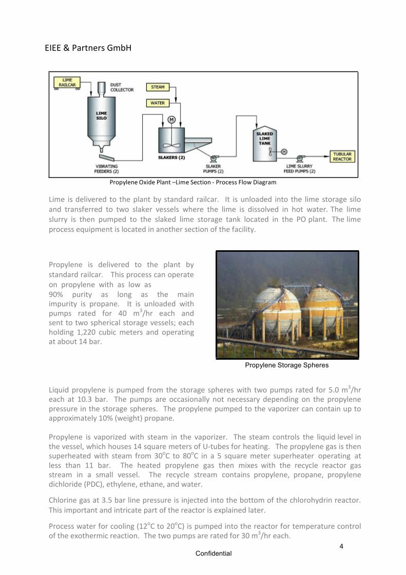
Propylene Oxide Plant –Lime Section -‐ Process Flow Diagram Lime is delivered to the plant by standard railcar. It is unloaded into the lime storage silo and transferred to two slaker vessels where the lime is dissolved in hot water. The lime slurry is then pumped to the slaked lime storage tank located in the PO plant. The lime process equipment is located in another section of the facility.
Propylene is delivered to the plant by standard railcar. This process can operate on propylene with as low as 90% purity as long as the main impurity is propane. It is unloaded with pumps rated for 40 m3/hr each and sent to two spherical storage vessels; each holding 1,220 cubic meters and operating at about 14 bar.
Propylene Storage Spheres Liquid propylene is pumped from the storage spheres with two pumps rated for 5.0 m3/hr each at 10.3 bar. The pumps are occasionally not necessary depending on the propylene pressure in the storage spheres. The propylene pumped to the vaporizer can contain up to approximately 10% (weight) propane. Propylene is vaporized with steam in the vaporizer. The steam controls the liquid level in the vessel, which houses 14 square meters of U-‐tubes for heating. The propylene gas is then superheated with steam from 30oC to 80oC in a 5 square meter superheater operating at less than 11 bar. The heated propylene gas then mixes with the recycle reactor gas stream in a small vessel. The recycle stream contains propylene, propane, propylene dichloride (PDC), ethylene, ethane, and water.
Chlorine gas at 3.5 bar line pressure is injected into the bottom of the chlorohydrin reactor. This important and intricate part of the reactor is explained later.
Process water for cooling (12oC to 20oC) is pumped into the reactor for temperature control of the exothermic reaction. The two pumps are rated for 30 m3/hr each.
Confidential
EIEE & Partners GmbH
5
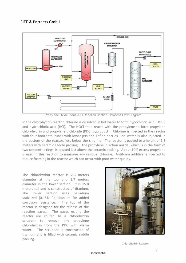
Propylene Oxide Plant –PO Reaction Section - Process Flow Diagram In the chlorohydrin reactor, chlorine is dissolved in hot water to form hypochloric acid (HOCl) and hydrochloric acid (HCl). The HOCl then reacts with the propylene to form propylene chlorohydrin and propylene dichloride (PDC) byproduct. Chlorine is injected in the reactor with four horizontal tubes with Kynar jets and Teflon nozzles. The water is also injected in the bottom of the reactor, just below the chlorine. The reactor is packed to a height of 1.8 meters with ceramic saddle packing. The propylene injection nozzle, which is in the form of two concentric rings, is located just above the ceramic packing. About 10% excess propylene is used in this reaction to minimize any residual chlorine. Antifoam additive is injected to reduce foaming in the reactor which can occur with poor water quality.
The chlorohydrin reactor is 2.6 meters diameter at the top and 1.7 meters diameter in the lower section. It is 15.8 meters tall and is constructed of titanium. The lower section uses palladium stabilized (0.15% Pd) titanium for added corrosion resistance. The top of the reactor is designed for the release of the reaction gases. The gases exiting the reactor are routed to a chlorohydrin scrubber to remove any propylene chlorohydrin from the PDC with warm water. The scrubber is constructed of titanium and is filled with ceramic saddle packing.
Chlorohydrin Reactor
Confidential
EIEE & Partners GmbH
6
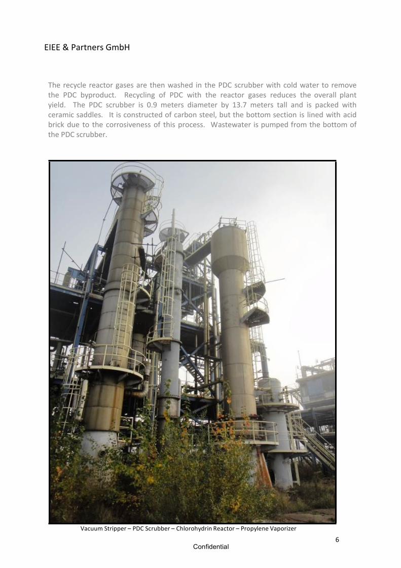
The recycle reactor gases are then washed in the PDC scrubber with cold water to remove the PDC byproduct. Recycling of PDC with the reactor gases reduces the overall plant yield. The PDC scrubber is 0.9 meters diameter by 13.7 meters tall and is packed with ceramic saddles. It is constructed of carbon steel, but the bottom section is lined with acid brick due to the corrosiveness of this process. Wastewater is pumped from the bottom of the PDC scrubber.
Vacuum Stripper – PDC Scrubber – Chlorohydrin Reactor – Propylene Vaporizer
Confidential
EIEE & Partners GmbH
7
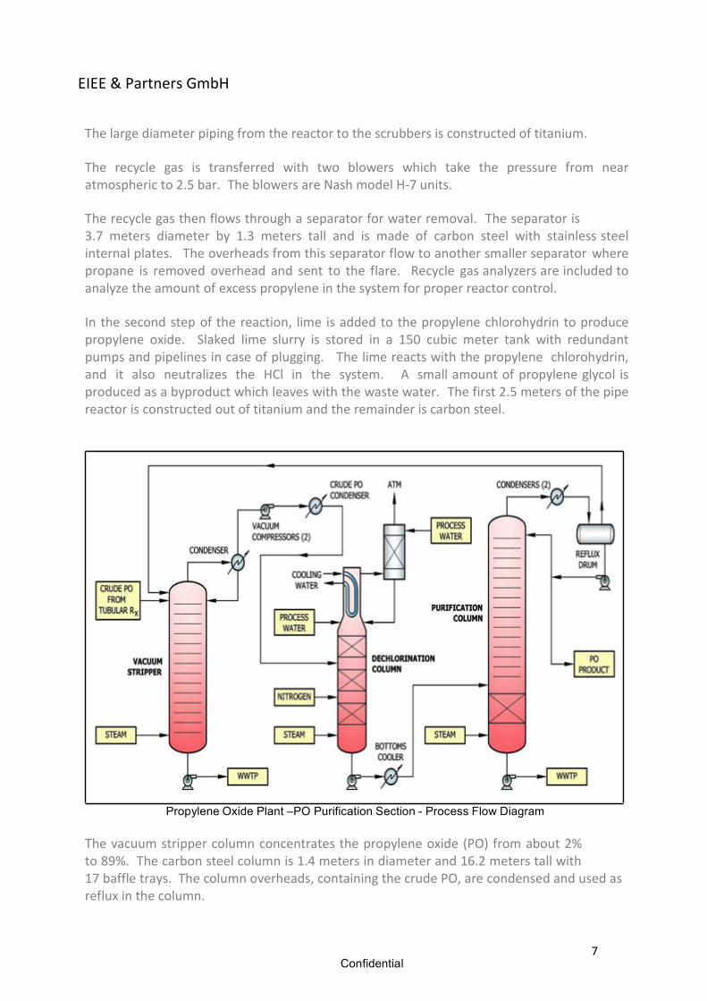
The large diameter piping from the reactor to the scrubbers is constructed of titanium. The recycle gas is transferred with two blowers which take the pressure from near atmospheric to 2.5 bar. The blowers are Nash model H-‐7 units. The recycle gas then flows through a separator for water removal. The separator is 3.7 meters diameter by 1.3 meters tall and is made of carbon steel with stainless steel internal plates. The overheads from this separator flow to another smaller separator where propane is removed overhead and sent to the flare. Recycle gas analyzers are included to analyze the amount of excess propylene in the system for proper reactor control. In the second step of the reaction, lime is added to the propylene chlorohydrin to produce propylene oxide. Slaked lime slurry is stored in a 150 cubic meter tank with redundant pumps and pipelines in case of plugging. The lime reacts with the propylene chlorohydrin, and it also neutralizes the HCl in the system. A small amount of propylene glycol is produced as a byproduct which leaves with the waste water. The first 2.5 meters of the pipe reactor is constructed out of titanium and the remainder is carbon steel.
Propylene Oxide Plant –PO Purification Section - Process Flow Diagram The vacuum stripper column concentrates the propylene oxide (PO) from about 2% to 89%. The carbon steel column is 1.4 meters in diameter and 16.2 meters tall with 17 baffle trays. The column overheads, containing the crude PO, are condensed and used as reflux in the column.
Confidential
EIEE & Partners GmbH
8
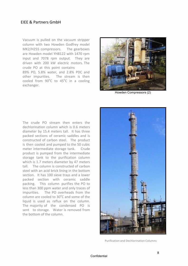
Vacuum is pulled on the vacuum stripper column with two Howden Godfrey model MK2/H255 compressors. The gearboxes are Howden model YH8122 with 1470 rpm input and 7078 rpm output. They are driven with 200 kW electric motors. The crude PO at this point contains 89% PO, 5.8% water, and 2.8% PDC and other impurities. The stream is then cooled from 90oC to 45oC in a cooling exchanger.
Howden Compressors (2)
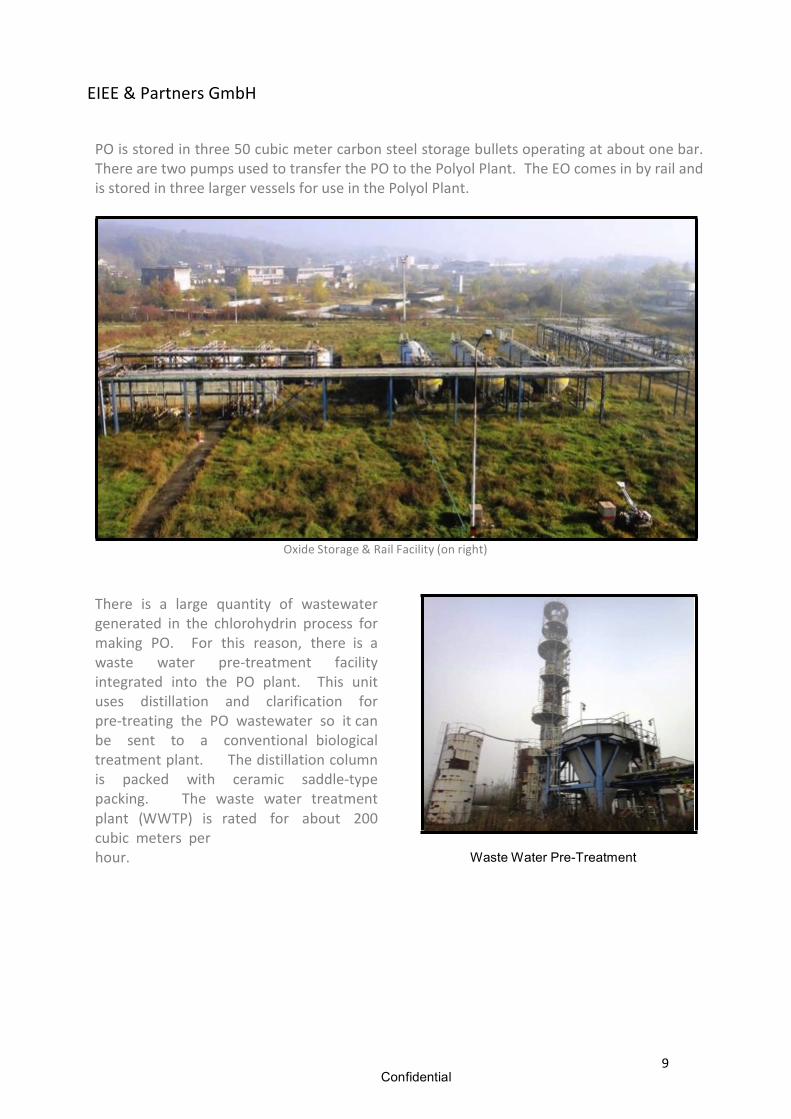
The crude PO stream then enters the dechlorination column which is 0.6 meters diameter by 15.4 meters tall. It has three packed sections of ceramic saddles and is constructed of carbon steel. The product is then cooled and pumped to the 50 cubic meter intermediate storage tank. Crude product is pumped from the intermediate storage tank to the purification column which is 1.7 meters diameter by 47 meters tall. The column is constructed of carbon steel with an acid brick lining in the bottom section. It has 100 sieve trays and a lower packed section with ceramic saddle packing. This column purifies the PO to less than 300 ppm water and only traces of impurities. The PO overheads from the column are cooled to 30oC and some of the liquid is used as reflux on the column. The majority of the condensed PO is sent to storage. Water is removed from the bottom of the column.
Purification and Dechlorination Columns
Confidential
EIEE & Partners GmbH
9
PO is stored in three 50 cubic meter carbon steel storage bullets operating at about one bar. There are two pumps used to transfer the PO to the Polyol Plant. The EO comes in by rail and is stored in three larger vessels for use in the Polyol Plant.
Oxide Storage & Rail Facility (on right) There is a large quantity of wastewater generated in the chlorohydrin process for making PO. For this reason, there is a waste water pre-‐treatment facility integrated into the PO plant. This unit uses distillation and clarification for pre-‐treating the PO wastewater so it can be sent to a conventional biological treatment plant. The distillation column is packed with ceramic saddle-‐type packing. The waste water treatment plant (WWTP) is rated for about 200 cubic meters per hour. Waste Water Pre-Treatment
Confidential
EIEE & Partners GmbH
10
Detailed Process Description – Polyol Plant
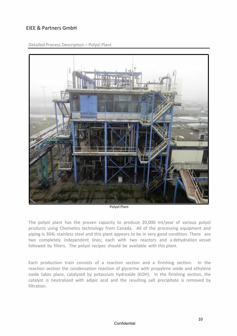
Polyol Plant
The polyol plant has the proven capacity to produce 20,000 mt/year of various polyol products using Chemetics technology from Canada. All of the processing equipment and piping is 304L stainless steel and this plant appears to be in very good condition. There are two completely independent lines; each with two reactors and a dehydration vessel followed by filters. The polyol recipes should be available with this plant.
Each production train consists of a reaction section and a finishing section. In the reaction section the condensation reaction of glycerine with propylene oxide and ethylene oxide takes place, catalyzed by potassium hydroxide (KOH). In the finishing section, the catalyst is neutralized with adipic acid and the resulting salt precipitate is removed by filtration.
Confidential
EIEE & Partners GmbH
11
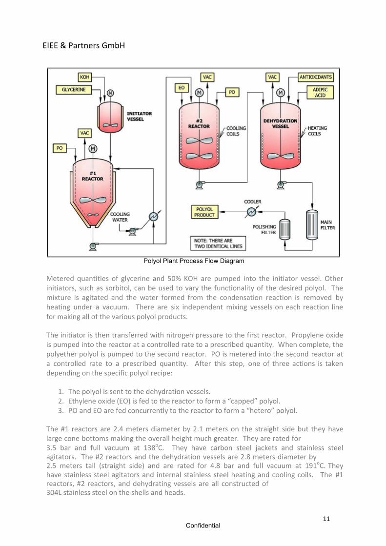
Polyol Plant Process Flow Diagram Metered quantities of glycerine and 50% KOH are pumped into the initiator vessel. Other initiators, such as sorbitol, can be used to vary the functionality of the desired polyol. The mixture is agitated and the water formed from the condensation reaction is removed by heating under a vacuum. There are six independent mixing vessels on each reaction line for making all of the various polyol products. The initiator is then transferred with nitrogen pressure to the first reactor. Propylene oxide is pumped into the reactor at a controlled rate to a prescribed quantity. When complete, the polyether polyol is pumped to the second reactor. PO is metered into the second reactor at a controlled rate to a prescribed quantity. After this step, one of three actions is taken depending on the specific polyol recipe:
1. The polyol is sent to the dehydration vessels. 2. Ethylene oxide (EO) is fed to the reactor to form a “capped” polyol. 3. PO and EO are fed concurrently to the reactor to form a “hetero” polyol.
The #1 reactors are 2.4 meters diameter by 2.1 meters on the straight side but they have large cone bottoms making the overall height much greater. They are rated for 3.5 bar and full vacuum at 138oC. They have carbon steel jackets and stainless steel agitators. The #2 reactors and the dehydration vessels are 2.8 meters diameter by 2.5 meters tall (straight side) and are rated for 4.8 bar and full vacuum at 191oC. They have stainless steel agitators and internal stainless steel heating and cooling coils. The #1 reactors, #2 reactors, and dehydrating vessels are all constructed of 304L stainless steel on the shells and heads.
Confidential
EIEE & Partners GmbH
12
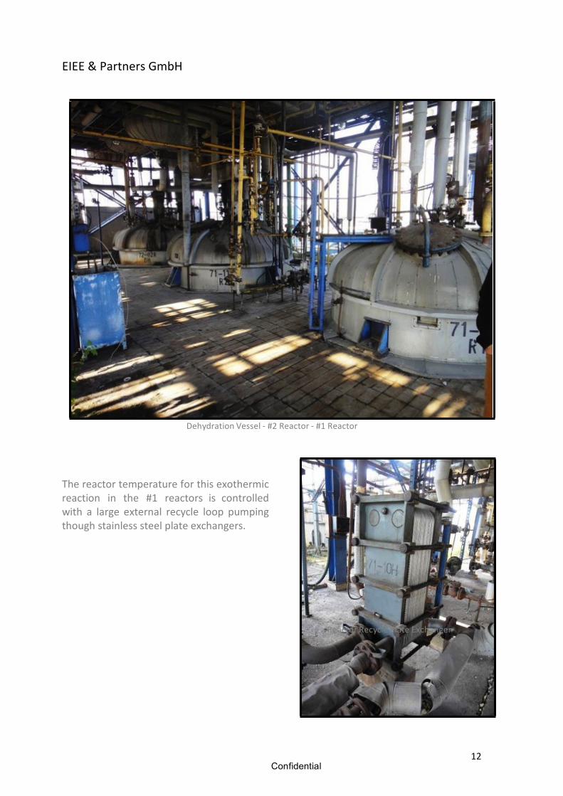
Dehydration Vessel -‐ #2 Reactor -‐ #1 Reactor The reactor temperature for this exothermic reaction in the #1 reactors is controlled with a large external recycle loop pumping though stainless steel plate exchangers.
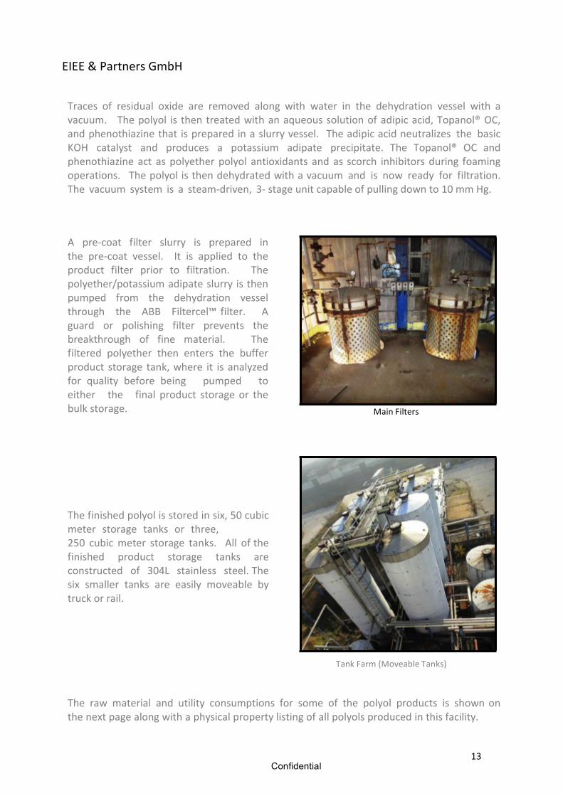
Reactor Recycle Plate Exchanger
Confidential
EIEE & Partners GmbH
13
Traces of residual oxide are removed along with water in the dehydration vessel with a vacuum. The polyol is then treated with an aqueous solution of adipic acid, Topanol® OC, and phenothiazine that is prepared in a slurry vessel. The adipic acid neutralizes the basic KOH catalyst and produces a potassium adipate precipitate. The Topanol® OC and phenothiazine act as polyether polyol antioxidants and as scorch inhibitors during foaming operations. The polyol is then dehydrated with a vacuum and is now ready for filtration. The vacuum system is a steam-‐driven, 3-‐ stage unit capable of pulling down to 10 mm Hg.
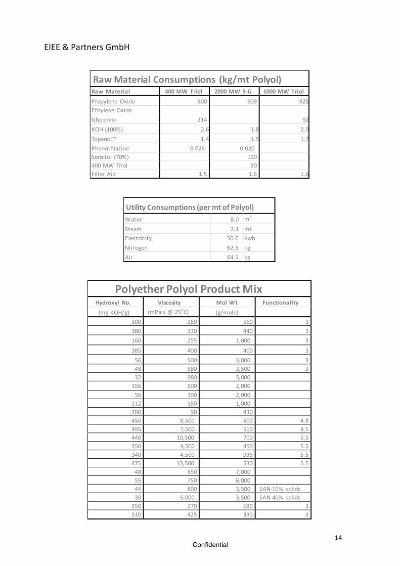
A pre-‐coat filter slurry is prepared in the pre-‐coat vessel. It is applied to the product filter prior to filtration. The polyether/potassium adipate slurry is then pumped from the dehydration vessel through the ABB Filtercel™ filter. A guard or polishing filter prevents the breakthrough of fine material. The filtered polyether then enters the buffer product storage tank, where it is analyzed for quality before being pumped to either the final product storage or the bulk storage.
Main Filters
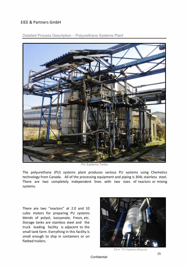
The finished polyol is stored in six, 50 cubic meter storage tanks or three, 250 cubic meter storage tanks. All of the finished product storage tanks are constructed of 304L stainless steel. The six smaller tanks are easily moveable by truck or rail.
Tank Farm (Moveable Tanks) The raw material and utility consumptions for some of the polyol products is shown on the next page along with a physical property listing of all polyols produced in this facility.
Confidential
EIEE & Partners GmbH
14
Raw Material Consumptions (kg/mt Polyol) Raw Material 400 MW Triol 2000 MW S-‐G 1000 MW Triol
Propylene Oxide 800 909 925 Ethylene Oxide Glycerine 214 92 KOH (100%) 2.6 1.8 2.0 Topanol™ 1.4 1.5 1.7 Phenothiazine 0.026 0.020 Sorbitol (70%) 110 400 MW Triol 30 Filter Aid 1.5 1.6 1.6
Utility Consumptions (per mt of Polyol) Water 8.0 m3
Steam 2.1 mt Electricity 50.0 kwh Nitrogen 62.5 kg Air 64.5 kg
Polyether Polyol Product Mix Hydroxyl No. Viscosity Mol Wt Functionality (mg KOH/g) (mPa.s @ 25oC) (g/mole)
300 280 560 3 380 330 440 3 160 255 1,000 3
385 400 400 3 56 500 3,000 3 48 580 3,500 3 32 980 5,000 156 600 2,000 56 300 2,000 112 150 1,000 280 90 430 450 8,500 600 4.8 495 7,500 510 4.5 440 10,500 700 5.5 350 4,500 450 5.5 340 4,500 935 5.5 475 13,500 530 5.5 48 850 7,000 55 750 6,000 44 800 3,500 SAN-‐10% solids 30 5,000 3,500 SAN-‐40% solids 250 270 680 3 510 425 330 3
Confidential
EIEE & Partners GmbH
15
Detailed Process Description – Polyurethane Systems Plant
PU Systems Tanks The polyurethane (PU) systems plant produces various PU systems using Chemetics technology from Canada. All of the processing equipment and piping is 304L stainless steel. There are two completely independent lines with two sizes of reactors or mixing systems.
There are two “reactors” at 2.0 and 10 cubic meters for preparing PU systems blends of polyol, isocyanate, Freon, etc. Storage tanks are stainless steel and the truck loading facility is adjacent to the small tank farm. Everything in this facility is small enough to ship in containers or on flatbed trailers.
10 m3 PU Systems Reactor
Confidential
EIEE & Partners GmbH
16
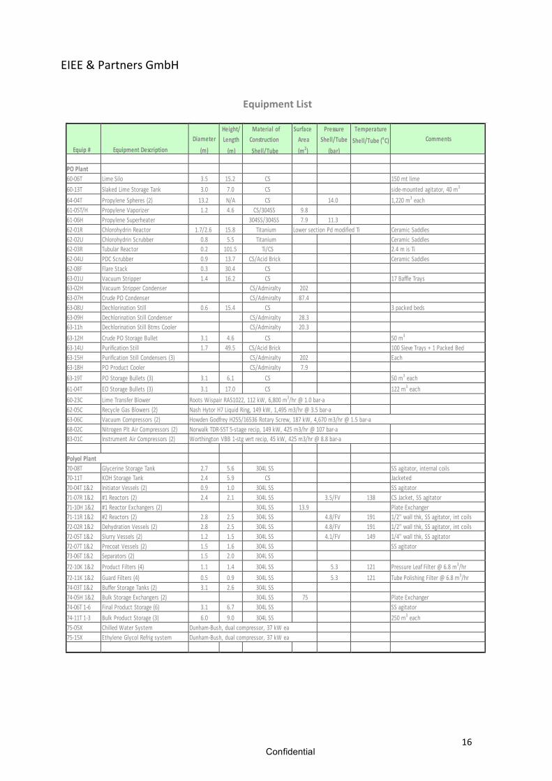
Equipment List
Equip #
Equipment Description
Diameter
(m)
Height/ Length (m)
Material of Construction Shell/Tube
Surface Area (m2)
Pressure Shell/Tube
(bar)
Temperature Shell/Tube (oC)
Comments
PO Plant 60-‐06T Lime Silo 3.5 15.2 CS 150 mt lime 60-‐13T Slaked Lime Storage Tank 3.0 7.0 CS side-‐mounted agitator, 40 m3
64-‐04T Propylene Spheres (2) 13.2 N/A CS 14.0 1,220 m3 each 61-‐05T/H Propylene Vaporizer 1.2 4.6 CS/304SS 9.8 61-‐06H Propylene Superheater 304SS/304SS 7.9 11.3 62-‐01R Chlorohydrin Reactor 1.7/2.6 15.8 Titanium Lower section Pd modified Ti Ceramic Saddles 62-‐02U Chlorohydrin Scrubber 0.8 5.5 Titanium Ceramic Saddles 62-‐03R Tubular Reactor 0.2 101.5 Ti/CS 2.4 m is Ti 62-‐04U PDC Scrubber 0.9 13.7 CS/Acid Brick Ceramic Saddles 62-‐08F Flare Stack 0.3 30.4 CS 63-‐01U Vacuum Stripper 1.4 16.2 CS 17 Baffle Trays 63-‐02H Vacuum Stripper Condenser CS/Admiralty 202 63-‐07H Crude PO Condenser CS/Admiralty 87.4 63-‐08U Dechlorination Still 0.6 15.4 CS 3 packed beds 63-‐09H Dechlorination Still Condenser CS/Admiralty 28.3 63-‐11h Dechlorination Still Btms Cooler CS/Admiralty 20.3 63-‐12H Crude PO Storage Bullet 3.1 4.6 CS 50 m3
63-‐14U Purification Still 1.7 49.5 CS/Acid Brick 100 Sieve Trays + 1 Packed Bed 63-‐15H Purification Still Condensers (3) CS/Admiralty 202 Each 63-‐18H PO Product Cooler CS/Admiralty 7.9 63-‐19T PO Storage Bullets (3) 3.1 6.1 CS 50 m3 each 61-‐04T EO Storage Bullets (3) 3.1 17.0 CS 122 m3 each 60-‐23C Lime Transfer Blower Roots Wispair RAS1022, 112 kW, 6,800 m3/hr @ 1.0 bar-‐a 62-‐05C Recycle Gas Blowers (2) Nash Hytor H7 Liquid Ring, 149 kW, 1,495 m3/hr @ 3.5 bar-‐a 63-‐06C Vacuum Compressors (2) Howden Godfrey H255/16536 Rotary Screw, 187 kW, 4,670 m3/hr @ 1.5 bar-‐a 68-‐02C Nitrogen Plt Air Compressors (2) Norwalk TDR-‐S5T 5-‐stage recip, 149 kW, 425 m3/hr @ 107 bar-‐a 83-‐01C Instrument Air Compressors (2) Worthington VBB 1-‐stg vert recip, 45 kW, 425 m3/hr @ 8.8 bar-‐a Polyol Plant 70-‐08T Glycerine Storage Tank 2.7 5.6 304L SS SS agitator, internal coils 70-‐11T KOH Storage Tank 2.4 5.9 CS Jacketed 70-‐04T 1&2 Initiator Vessels (2) 0.9 1.0 304L SS SS agitator 71-‐07R 1&2 #1 Reactors (2) 2.4 2.1 304L SS 3.5/FV 138 CS Jacket, SS agitator 71-‐10H 1&2 #1 Reactor Exchangers (2) 304L SS 13.9 Plate Exchanger 71-‐11R 1&2 #2 Reactors (2) 2.8 2.5 304L SS 4.8/FV 191 1/2" wall thk, SS agitator, int coils 72-‐02R 1&2 Dehydration Vessels (2) 2.8 2.5 304L SS 4.8/FV 191 1/2" wall thk, SS agitator, int coils 72-‐05T 1&2 Slurry Vessels (2) 1.2 1.5 304L SS 4.1/FV 149 1/4" wall thk, SS agitator 72-‐07T 1&2 Precoat Vessels (2) 1.5 1.6 304L SS SS agitator 73-‐06T 1&2 Separators (2) 1.5 2.0 304L SS 72-‐10K 1&2 Product Filters (4) 1.1 1.4 304L SS 5.3 121 Pressure Leaf Filter @ 6.8 m3/hr 72-‐11K 1&2 Guard Filters (4) 0.5 0.9 304L SS 5.3 121 Tube Polishing Filter @ 6.8 m3/hr 74-‐03T 1&2 Buffer Storage Tanks (2) 3.1 2.6 304L SS 74-‐05H 1&2 Bulk Storage Exchangers (2) 304L SS 75 Plate Exchanger 74-‐06T 1-‐6 Final Product Storage (6) 3.1 6.7 304L SS SS agitator 74-‐11T 1-‐3 Bulk Product Storage (3) 6.0 9.0 304L SS 250 m3 each 75-‐05X Chilled Water System Dunham-‐Bush, dual compressor, 37 kW ea 75-‐15X Ethylene Glycol Refrig system Dunham-‐Bush, dual compressor, 37 kW ea