Embed Size (px)
Citation preview
Eindhoven University of Technology
MASTER
The mechanical possibilities of mycelium materials
Lelivelt, R.J.J.
Award date:2015
Link to publication
DisclaimerThis document contains a student thesis (bachelor's or master's), as authored by a student at Eindhoven University of Technology. Studenttheses are made available in the TU/e repository upon obtaining the required degree. The grade received is not published on the documentas presented in the repository. The required complexity or quality of research of student theses may vary by program, and the requiredminimum study period may vary in duration.
General rightsCopyright and moral rights for the publications made accessible in the public portal are retained by the authors and/or other copyright ownersand it is a condition of accessing publications that users recognise and abide by the legal requirements associated with these rights.
• Users may download and print one copy of any publication from the public portal for the purpose of private study or research. • You may not further distribute the material or use it for any profit-making activity or commercial gain

The mechanical possibilities of mycelium materials
R.J.J. Lelivelt
Supervisors: ir. G. Lindner prof. dr. ing. P.M. Teuffel ir. H. Lamers Unit Structural Design (SD) Faculty of Architecture, Building and Planning (ABP) Eindhoven university of technology (TU/e) March 2, 2015

0 Introduction
2

0 Introduction
There was a time when he would walk in my woods. But now he has a mind of metal, and wheels. He no longer cares for
growing things.
Treebeard; The Lord of the Rings: the Two Towers; J.R.R. Tolkien, 1954
“”
3

0 Introduction
Contents
Introduction ............................................................................................................................................ 6
Part 1 Biobased building materials – an overview ............................................................................ 7
1.1 Introduction .................................................................................................................................. 7
1.2 Selecting the subgroup ................................................................................................................. 7
1.3 Strategies for sustainable materials.............................................................................................. 9
1.4 An assessment of biobased materials ......................................................................................... 13
1.4.1 Used-as-grown materials ..................................................................................................... 13
1.4.2 Engineered wood products .................................................................................................. 15
1.4.3 Bio-based composites .......................................................................................................... 16
1.5 Conclusions ................................................................................................................................. 22
Part 2 Mycelium materials – a fully biobased composite ............................................................... 25
2.1 Introduction ................................................................................................................................ 25
2.2 Fungi- selection and characterization ......................................................................................... 25
2.3 Overview of growing methods .................................................................................................... 28
2.3.1 Pretreating the substrate - sterile or just really clean? ....................................................... 30
2.3.2 Open or closed growing – a question of scale ..................................................................... 31
2.4 Composition of mycelium-based materials ................................................................................ 33
2.4.1 Fungus .................................................................................................................................. 33
2.4.2 Fiber ..................................................................................................................................... 34
Part 3 Composite material models .................................................................................................. 35
3.1 Introduction ................................................................................................................................ 35
3.2 Material model choice ................................................................................................................ 35
3.2.1 Soil Mechanics approach ..................................................................................................... 35
3.2.2 The generally orthotropic model – the wood approach ...................................................... 36
3.2.3 Composite approach ............................................................................................................ 37
3.3 Rotated compliance matrix ......................................................................................................... 38
3.4 Composite stiffness ..................................................................................................................... 42
3.5 Short fiber adaptations ............................................................................................................... 45
Part 4 Experiments .......................................................................................................................... 54
4.1 Introduction ................................................................................................................................ 54
4.2 Method ....................................................................................................................................... 54
4.2.1 Materials .............................................................................................................................. 54
4.2.2 Growing Process................................................................................................................... 54
4
0 Introduction
4.2.3 Compressive tests ................................................................................................................ 56
4.3 Results and Discussion ................................................................................................................ 56
4.3.1 Infection rate ........................................................................................................................ 56
4.3.2 Visual inspection of growth ................................................................................................. 57
4.3.3 Compressive results ............................................................................................................. 59
Part 5 Conclusions and Recommendations ..................................................................................... 63
Part 6 Acknowledgements ............................................................................................................... 67
Part 7 Appendices ............................................................................................................................ 72
7.1 E-mail from substrate producer Mycobois recommending C. versicolor ................................... 72
7.2 Interview with designer Maurizio Montalti concerning the growing conditions of mycelium-based materials ................................................................................................................................. 73
7.3 Report of a company visit to CNC – the world’s largest producer of substrate for mycelium cultivation ......................................................................................................................................... 75
7.4 General protocol for creating mycelium-based material samples ............................................. 82
5

0 Introduction
Introduction In the transition towards a world in dynamic equilibrium with its natural resources, oil and all oil based products must be replaced by more renewable and recyclable alternatives.
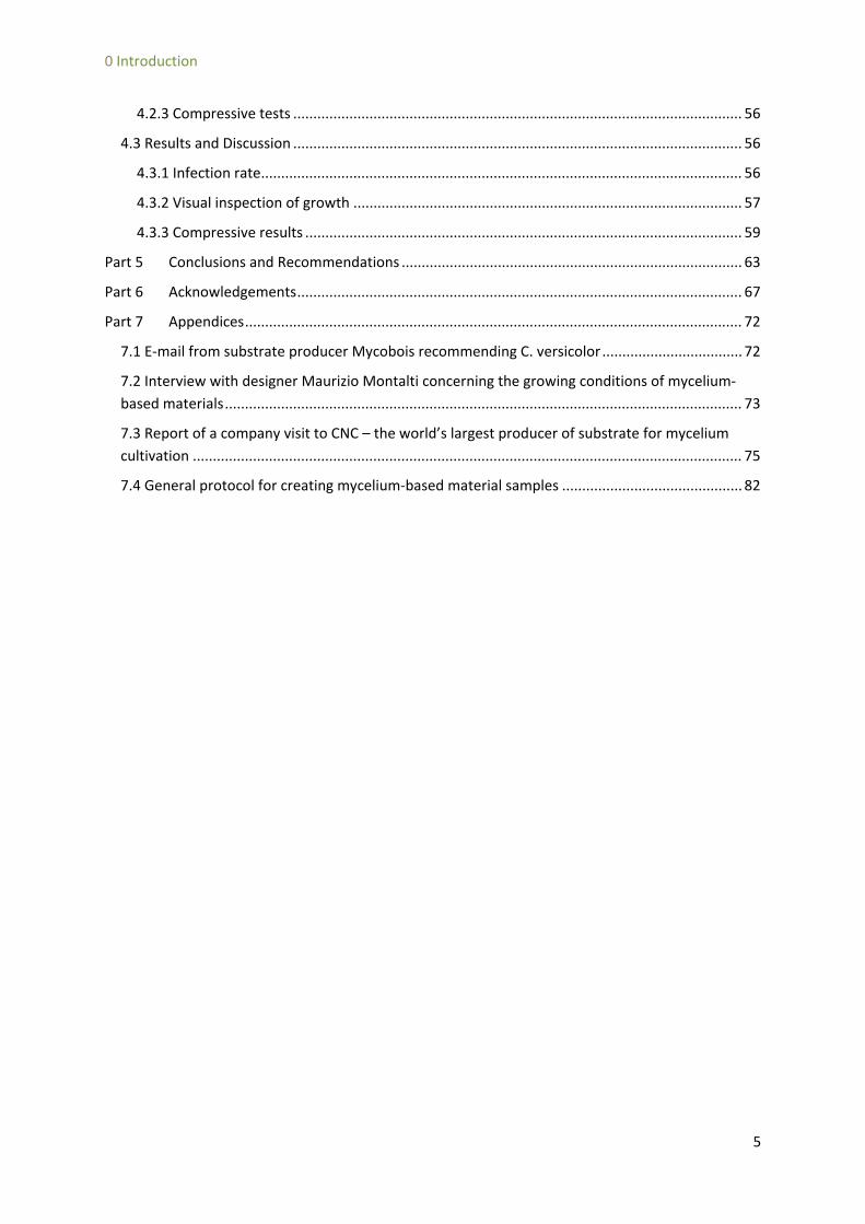
Mycelium-based materials are renewable and recyclable and can replace, among others, various plastics. A mycelium-based material is a composite consisting of a natural reinforcement or filler, such as hemp fibers, and the mycelium of a fungus. A mycelium is a dense network of thin strands, called hyphae that grow and fuse together into a solid material. The mycelium acts as a three-dimensional matrix that binds the natural substrate into a lightweight material, comparable to expanded polystyrene.
Figure 1; A mycelium-based material is a composite with a fungal mycelium as matrix and a natural reinforcement, such as hemp fiber
Mycelium-based materials are fully biobased and biodegradable and can be discarded at the end of the life cycle with little or no cost and environmental damage. For these reasons, mycelium-based materials have already been applied as packaging in the U.S. [1] and are increasingly being discovered by artists, designers and architects. Recently, an outdoor pavilion of the material was realized in New York. [2] Mycelium-based materials would be especially beneficial as a structural material in the building industry, as that industry currently uses many polluting and non-recyclable materials in large quantities.
Research on the mechanical performance of mycelium-based materials is limited. The aim of this project is to perform an explorative research to determine the mechanical properties of a mycelium-hemp composite by means of experimental testing and development of a coinciding material model. The project intents to achieve this goal by four subparts:
i. Create an overview of existing bio-based materials and the factors that influence the sustainable impact of materials
ii. Make a distillation of the key factors that determine the production, properties and performance of mycelium-based materials
iii. Setting up an appropriate material model to gain insight into the mechanical behavior of mycelium-based materials.
iv. Perform experimental compression tests on samples to ascertain indicative engineering constants of mycelium-hemp fiber composites.
Using the findings of these four parts, an explorative view can be given on the use of mycelium-based materials as a structural material in the building industry.
6
Part 1 Biobased building materials – an overview
Part 1 Biobased building materials – an overview
1.1 Introduction Mycelium-based materials are interesting because of their sustainability. However many more materials are, or at least claim to be, sustainable. The purpose of this chapter is to categorize and asses this group of sustainable materials. Such a comparison of existing sustainable materials is useful as it allows us to conclude if a need for new sustainable materials is present and if mycelium-based materials can fulfil this need. The assessment will be executed by first defining the exact subgroup of materials to compare, then introducing the currently available strategies for sustainable materials and then using those strategies as a framework to assess the selected subgroup of materials. The chapter will end with conclusions on the position of mycelium-materials within this subgroup.
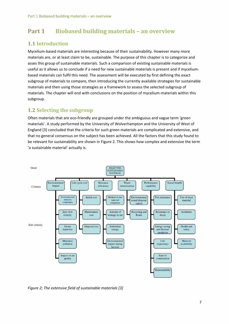
1.2 Selecting the subgroup Often materials that are eco-friendly are grouped under the ambiguous and vague term ‘green materials’. A study performed by the University of Wolverhampton and the University of West of England [3] concluded that the criteria for such green materials are complicated and extensive, and that no general consensus on the subject has been achieved. All the factors that this study found to be relevant for sustainability are shown in Figure 2. This shows how complex and extensive the term ‘a sustainable material’ actually is.
Figure 2; The extensive field of sustainable materials [3]
7
Part 1 Biobased building materials – an overview
There are neither resources nor priorities to asses all available materials on all the relevant criteria for sustainability. Furthermore extensive literature is available on the subject of green materials in general. [3, 4, 5]
For these reasons this report will focus on a more easily definable subgroup of green materials; bio-based materials. A bio-based material is here defined as: “a material of which at least one of the components can be biologically grown and is fully renewable”.
Within this definition there is still a broad field of materials including straw bale construction, living structures such as trees and bio-based textiles. The author realizes that a categorization of all bio-based materials could never be complete, if only because one can never know if one knows everything. However a thorough literature was performed by searching in academic literature on sustainable materials. The search was focused on materials that can be structurally used in the building industry. This means that it can carry load and has a high strength and stiffness. A selection of materials was made and though many more materials exist, only those found in the scientific literature were included in the overview of this chapter.
The selected materials can be categorized into three categories; used-as-grown materials, engineered woods and composites. A used-as-grown material is a material that requires little or no processing to be usable. Engineered woods are made from processed wood, wood-waste or wood-like materials. The third category consists of composite materials. A composite material consists of a high-strength reinforcement and a high-ductility matrix [6]. Great progress has been made in using natural fibers, such as hemp or flax, as reinforcement in composites. However sustainable matrices are less common. In fact a composite consisting of a natural matrix and a synthetic reinforcement is as yet unknown. The composites are therefore further divided based on their matrices. A difference is made in mineral matrices, petroleum-based matrices and starch-based matrices.
A bio-based material is a material of which at least one of the components can be biologically grown and is fully renewable
Definition 1; biobased material
8

Part 1 Biobased building materials – an overview
1.3 Strategies for sustainable materials There are several routes a material can take to be or become more sustainable. Though numerous different terms and labels for strategies exist, three fundamentally distinct strategies have been found. These strategies fit into a hierarchy in which the first strategy ranks lowest in terms of sustainability and the third strategy ranks highest.
The first strategy is the easiest to implement in current material and product design; the waste hierarchy. This strategy focuses on the waste produced during the production process of a material or product and seeks to minimize that waste through a series of measures. In the U.K. this strategy is
Figure 4; the waste hierarchy
Figure 3; categorization of bio-based materials
9
Part 1 Biobased building materials – an overview
better known as waste minimization whilst in the U.S. the term pollution prevention is more common [7].
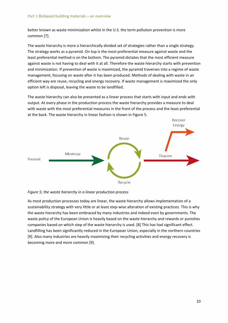
The waste hierarchy is more a hierarchically divided set of strategies rather than a single strategy. The strategy works as a pyramid. On top is the most preferential measure against waste and the least preferential method is on the bottom. The pyramid dictates that the most efficient measure against waste is not having to deal with it at all. Therefore the waste hierarchy starts with prevention and minimization. If prevention of waste is maximized, the pyramid traverses into a regime of waste management; focusing on waste after it has been produced. Methods of dealing with waste in an efficient way are reuse, recycling and energy recovery. If waste management is maximized the only option left is disposal, leaving the waste to be landfilled.
The waste hierarchy can also be presented as a linear process that starts with input and ends with output. At every phase in the production process the waste hierarchy provides a measure to deal with waste with the most preferential measures in the front of the process and the least preferential at the back. The waste hierarchy in linear fashion is shown in Figure 5.
Figure 5; the waste hierarchy in a linear production process
As most production processes today are linear, the waste hierarchy allows implementation of a sustainability strategy with very little or at least step-wise alteration of existing practices. This is why the waste hierarchy has been embraced by many industries and indeed even by governments. The waste policy of the European Union is heavily based on the waste hierarchy and rewards or punishes companies based on which step of the waste hierarchy is used. [8] This has had significant effect. Landfilling has been significantly reduced in the European Union, especially in the northern countries [9]. Also many industries are heavily maximizing their recycling activities and energy recovery is becoming more and more common [9].
10

Part 1 Biobased building materials – an overview
However the waste hierarchy also has disadvantages. First of all, it only allows a reduction of the problem. In other words; it only allows processes to be less bad, not good. Furthermore its hierarchical nature is a simplification that might seem very intuitive but is not necessarily always correct. For instance imagine a process where an increase in input results in a product that can be recycled ad infinitum without any damage to the environment. The waste hierarchy states that waste prevention outranks recycling and would never allow the product to come in its infinite recycling regime. Another failure of the waste hierarchy is that it does not include composting as an option for reuse. Composting is the natural decaying process of materials into usable nutrients. Such a process is not at all damaging to the environment and would be a very green solution to any waste problem.
The second strategy builds on the critique on the waste hierarchy. Instead of thinking in linear processes, the second strategy proposes circular processes where each cycle of the process can occur without any damage to the environment. It was the Swiss architect Walter Stahel in the 1970’s that coined the term ‘cradle-to-cradle’ to counter the ‘cradle-to-grave’ solutions of the waste hierarchy. In such circular processes, waste becomes a new resource. The popular phrase ‘waste = food’ is often used here. In contradiction to the waste hierarchy, which only seeks to minimize the negative impact of waste, the circular economy transforms waste into usable resource. The composting process which was absent in the waste hierarchy has become the central process in this strategy. However, this circular process is only truly circular if the cycles could be repeated infinitely. This creates the extra demand that all processes within a cycle have to occur with renewable resources and renewable energy.
0
100
200
300
400
1995 2000 2005 2010
Kg/capita of waste landfilled in the
EU-27
Year
Figure 6; kg of landfilled waste per capita in the EU-27 countries. [9]
11

Part 1 Biobased building materials – an overview
Figure 7; the circular economy
William McDonough, whose firm has trademarked the cradle-to-cradle approach, has introduced a strategy that goes even further than the circular economy. He envisions an approach where production cycles are not only neutral to the environment, but also provide an actual positive stimulus with each cycle. He terms this principle the ‘Triple-Top-Line’ with which he means that a product must not only have a positive impact on economy and society, but also on the environment.
Figure 8; William McDonough's Triple-Top-Line approach
12

Part 1 Biobased building materials – an overview
An explanatory example might be useful in distinguishing the three strategies more clearly. In the Himalaya’s, trips to climb the Mount Everest are becoming more and more popular. However these trips also have a large negative influence on the environment, mainly because of the oxygen tanks that are left by the climbers when empty. The waste hierarchy solution to the problem would be to restrict the amount of tanks that climbers would be allowed to take up in the first place, reducing the amount of tanks left after. The circular economy approach would be to obligate climbers to bring down every oxygen tank they take up, making each climb environmentally neutral. The Triple-Top-Line solution would be to obligate climbers to take their tanks with them but to also bring down at least one tank that is already at the top. In this solution each climb actually makes the mountain cleaner.
Figure 9; the three sustainable strategies
1.4 An assessment of biobased materials The three sustainable strategies will now be used to assess the subgroups of biobased materials that were defined in section 1.2. Each group will be assessed on its ability to fit into one of the three models. As this project seeks to explore the mechanical possibilities of mycelium materials, the mechanical performance of each subgroup will also be listed. This will provide a background on which to compare the results of the experiments in Part 4.
1.4.1 Used-as-grown materials The first subgroup of the biobased categorization is the used-as-grown materials. These are materials that can be used with minimum processing after harvest and that need no other component to be functional. The two most important used-as-grown materials are timber and bamboo.
Timber is an important material in today’s construction industry and is often one of the first materials to come to mind when thinking about green materials. Though the number of wood
13
Part 1 Biobased building materials – an overview
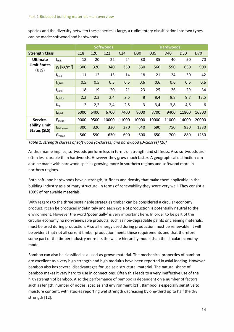
species and the diversity between these species is large, a rudimentary classification into two types can be made: softwood and hardwoods.
Softwoods Hardwoods Strength Class C18 C20 C22 C24 D30 D35 D40 D50 D70
Ultimate Limit States
(ULS)
fm,k 18 20 22 24 30 35 40 50 70
ρk [kg/m3] 300 320 340 350 530 560 590 650 900
ft,0,k 11 12 13 14 18 21 24 30 42
ft,90,k 0,5 0,5 0,5 0,5 0,6 0,6 0,6 0,6 0,6
fc,0,k 18 19 20 21 23 25 26 29 34
fc,90,k 2,2 2,3 2,4 2,5 8 8,4 8,8 9,7 13,5
fv,k 2 2,2 2,4 2,5 3 3,4 3,8 4,6 6
E0,05 6000 6400 6700 7400 8000 8700 9400 11800 16800
Service-ability Limit States (SLS)
Emean 9000 9500 10000 11000 10000 10000 11000 14000 20000
E90, mean 300 320 330 370 640 690 750 930 1330
Gmean 560 590 630 690 600 650 700 880 1250
Table 1; strength classes of softwood (C-classes) and hardwood (D-classes) [10]
As their name implies, softwoods perform less in terms of strength and stiffness. Also softwoods are often less durable than hardwoods. However they grow much faster. A geographical distinction can also be made with hardwood species growing more in southern regions and softwood more in northern regions.
Both soft- and hardwoods have a strength, stiffness and density that make them applicable in the building industry as a primary structure. In terms of renewability they score very well. They consist a 100% of renewable materials.
With regards to the three sustainable strategies timber can be considered a circular economy product. It can be produced indefinitely and each cycle of production is potentially neutral to the environment. However the word ‘potentially’ is very important here. In order to be part of the circular economy no non-renewable products, such as non-degradable paints or cleaning materials, must be used during production. Also all energy used during production must be renewable. It will be evident that not all current timber production meets these requirements and that therefore some part of the timber industry more fits the waste hierarchy model than the circular economy model.
Bamboo can also be classified as a used-as-grown material. The mechanical properties of bamboo are excellent as a very high strength and high modulus have been reported in axial loading. However bamboo also has several disadvantages for use as a structural material. The natural shape of bamboo makes it very hard to use in connections. Often this leads to a very ineffective use of the high strength of bamboo. Also the performance of bamboo is dependent on a number of factors such as length, number of nodes, species and environment [11]. Bamboo is especially sensitive to moisture content, with studies reporting wet strength decreasing by one-third up to half the dry strength [12].
14
Part 1 Biobased building materials – an overview
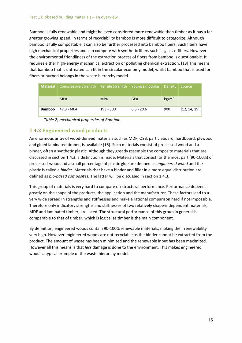
Bamboo is fully renewable and might be even considered more renewable than timber as it has a far greater growing speed. In terms of recyclability bamboo is more difficult to categorize. Although bamboo is fully compostable it can also be further processed into bamboo fibers. Such fibers have high mechanical properties and can compete with synthetic fibers such as glass e-fibers. However the environmental friendliness of the extraction process of fibers from bamboo is questionable. It requires either high-energy mechanical extraction or polluting chemical extraction. [13] This means that bamboo that is untreated can fit in the circular economy model, whilst bamboo that is used for fibers or burned belongs in the waste hierarchy model.
Material Compressive Strength Tensile Strength Young's modulus Density Source
MPa MPa GPa kg/m3
Bamboo 47.3 - 68.4 193 - 300 6.5 - 20.6 900 [12, 14, 15]
Table 2; mechanical properties of Bamboo
1.4.2 Engineered wood products An enormous array of wood-derived materials such as MDF, OSB, particleboard, hardboard, plywood and glued laminated timber, is available [16]. Such materials consist of processed wood and a binder, often a synthetic plastic. Although they greatly resemble the composite materials that are discussed in section 1.4.3, a distinction is made. Materials that consist for the most part (90-100%) of processed-wood and a small percentage of plastic glue are defined as engineered wood and the plastic is called a binder. Materials that have a binder and filler in a more equal distribution are defined as bio-based composites. The latter will be discussed in section 1.4.3.
This group of materials is very hard to compare on structural performance. Performance depends greatly on the shape of the products, the application and the manufacturer. These factors lead to a very wide spread in strengths and stiffnesses and make a rational comparison hard if not impossible. Therefore only indicatory strengths and stiffnesses of two relatively shape-independent materials, MDF and laminated timber, are listed. The structural performance of this group in general is comparable to that of timber, which is logical as timber is the main component.
By definition, engineered woods contain 90-100% renewable materials, making their renewability very high. However engineered woods are not recyclable as the binder cannot be extracted from the product. The amount of waste has been minimized and the renewable input has been maximized. However all this means is that less damage is done to the environment. This makes engineered woods a typical example of the waste hierarchy model.
15

Part 1 Biobased building materials – an overview
Material Compressive Strength
Tensile Strength Young's modulus
Density Source
MPa MPa GPa kg/m3
Glued laminated Timber
24 - 31 16.5 - 26 11.6 - 14.7 380 - 450
[17]
MDF 10 18 4 750 [18]
Table 3; structural performance of two engineered wood products
1.4.3 Bio-based composites As stated in the introduction, this project considers a bio-based composite as a natural fiber joined with a mineral, plastic or bio-based matrix. As the fibers that are used with each of the matrices are comparable [19] [20] [21], a separate section on natural fibers is added that covers the important characteristics of these fibers.
1.4.3.1 Natural fibers Natural fibers are fibers that are extracted from biological sources, such as plants and animals. A rudimentary classification is made in animal and plant fibers. As plant fibers are the most widely available and the most commonly used this section will focus on that class of fibers. Plant fibers can be further organized in leaf, bast, seed, core and reed fibers. [19]
Figure 10; Hierarchy of flax bundles as defined by Bos et al [22]
All plant-derived natural fibers show a similar structure. A natural fiber essentially is a hollow tube with progressively smaller tubes in the perimeter. Bos et al [22] made a study of flax fibers in which they made a clear distinction between the different levels of bundles and defined labels for each level which can be seen in Figure 10. Such a taxonomy can be used for all natural fibers. Such a tube structure makes the fibers lightweight and very strong in the axial direction, see Table 6. At the molecular level natural fibers are a composite of rigid-high strength cellulose embedded in a lignin matrix. Therefore, high cellulose content predicts high tensile strength. Some fibers also contain a
16

Part 1 Biobased building materials – an overview
waxy outer layer that provides a natural protection against bacteria and other sources of disease or infection. The contents of a collection of natural fibers is shown in Table 4.
Fiber Cellulose (wt %)
Hemicellulose (wt %)
Lignin (wt %)
Waxes (wt %)
Source
Bagasse 55,2 16,8 25,3 - [19] banana 60-65 11_21 19-24 - [23] Bamboo 26-43 30 21-31 - [19] Flax 71 18,6-20,6 2,2 1,5 [19] Kenaf 72 20,3 9 - [19] Jute 61-71 14-20 12-13 0.5 [19] Hemp 68 15 10 0.8 [19] Ramie 68,6-76,2 13-16 0,6-0,7 0.3 [19] Abaca 56-63 20-25 7-9 3 [19] Sisal 65 12 9.9 2 [19] Cotton 90 > 8 < 2 - [23] Coir 32-43 0,15-0,25 40-45 - [19] Oil Palm 65 - 29 - [19] Pineapple 81 - 12.7 - [19] Curaua 73.6 9.9 7.5 - [19] Wheat Straw 38-45 15-31 12-20 - [19] Rice husk 35-45 19-25 20 14-17 [19] Rice Straw 41-57 33 8-19 8-38 [19] Table 4; Contents of several natural fibers
Since the introduction of synthetic fibers such as glass fiber, kevlar and ultra-high molecular weight polyethylene, natural fibers have been completely replaced in industrial applications. Recently however, natural fibers are being increasingly reconsidered. The main reason is the sustainable nature of natural fibers and the (possibly) low cost. Wambua et al [24] created an overview of the advantages of natural fibers which is listed in
Table 5. Also Satyanarayana et al [23] made such a comparison in which natural fibers proved to be equal if not superior to synthetic fibers.
17

Part 1 Biobased building materials – an overview
Natural Fibres Glass Fibres Density Low Twice that of NF Cost Low Low, but higher than NF Renewability Yes No Recyclability Yes No Energy consumption Low High Distribution Wide Wide CO2 neutral Yes No
Abrasion to machines No Yes Health risk when inhaled No Yes Biodegradable Yes No
Table 5; the advantages of natural fibers compared to glass fiber according to Wambua et al [24]
Due to these advantages natural fibers are being increasingly used in structural composites, especially in the automotive industry [21]. However the use of natural fibers also has a number of concerns. First of all due to their biological nature, natural fibers show a large spread in performance over different harvests. Secondly natural fibers show a very hydrophilic behavior, for instance Abaca leaf fiber can hold up to 1,6 times its own weight in water [25]. This makes natural fibers very sensitive to moisture content [25]. This is especially problematic when using the fibers as reinforcement in composites with a polymer matrix. Such a matrix is hydrophobic and therefore the fibers will not be wetted as well as synthetic fibers. This leads to a weaker chemical bond between matrix and fiber. Consequently, there is a less efficient stress transfer in the composite and therefore a lower performance of the composite as a whole. Many different treatments, such as alkalization, have been proposed to improve this interfacial effect between fiber and matrix [25, 26, 27, 28] with mixed results. Another problem with high water absorption is that an increase in moisture content will lead to a greater volume increase of the fiber than the matrix. This creates extra stresses in the composites which can lead to a reduction in strength or even fracture at the fiber-matrix interface [19].
When using natural fibers the mechanical performance is of key importance. Many researchers have conducted experiments on natural fibers to determine this performance. The compiled results of several studies are shown in Table 6. Although the performance in general is high enough to be comparable to synthetic fibers, a large spread in results can be observed. This might in part be due to the mentioned effect of different harvests. However another effect that causes the large spread is that tensile strength increases as a smaller tube is tested. It is therefore important to list the diameter, or even better the sectional surface, of the fiber that was used during testing but in practice few researchers do this. It is likely that most researchers work at the technical fiber level but explicit determination of the fiber size needs to be included in the testing protocol.
18

Part 1 Biobased building materials – an overview
Fiber Tensile Strength (MPa)
Tensile strain to failure
(%)
Young's modulus (GPa)
Density (g/cm3)
Source
Bagasse 222 1,1 17,9-27,1 - [23] Banana 700-800 2,5-3,7 27-32 - [23] Bamboo 500-575 1,9-3,2 27-40 - [29] Flax 780-1500 1,2-2,4 60-80 - [23] 800-1500 1,2-1,6 60-80 1,40 [24] Kenaf 930 1,6 53 - [19] Jute 400-800 1,5-1,8 10-30 - [23] 400-800 1,8 10-30 1,46 [24] Hemp 690 1,6 70 - [19] 550-900 1,6 70 1,48 [24] 660±83 - 24±8,5 - [26] 2140 (504) 1,8(0,7) 143,2(26,7) - [27] Ramie 500-870 1,2 44 - [23] 500 2 44 1,50 [24] Abaca 400 3-10 12 - [19] Sisal 530-630 3,64-5,12 17-22 - [23] 600-700 2-3 38 1,33 [24] Cotton 400 - 12 - [23] 400 3-10 12 1,51 [24] Coir 220 23,9-51,4 6 - [23] 220 15-25 6 1,25 [24] Oil Palm 248 3,2 25 - [19] Pineapple 180 3,2 82 - [23] Curaua 87-310 4-4,9 34-96 - [23] E-glass 2400 3 73 2,55 [24]
Table 6; mechanical performance of natural fibers. Values in brackets represent a standard deviation.
1.4.3.2 Mineral matrix There have been certain developments in natural fibers combined with a mineral matrix. Common are cement, lime [4] and adobe. The natural fiber is not added to improve structural performance but to decrease weight and to increase thermal properties. Therefore the strength of the matrix is the upper limit of these composites (which would only occur at a fiber percentage of 0%).
19

Part 1 Biobased building materials – an overview
Material Compressive Strength Young's modulus Density Source
MPa MPa kg/m3
Hemp-lime 0.4 24 445 [4]
Sawdust, paper-lime 0.06 - 0.8 - 473 - 702 [4]
Date fiber –cement 5 - 35 - 750 - 1900 [30]
Table 7; mechanical performance of bio-based composites with a mineral matrix.
Through hydration the mineral matrix chemically reacts with the natural fibers. This makes any form of recycling very hard. If recycling is done, only the unreacted parts of a composite can be recovered and even then at great cost. As minerals are non-renewable only the natural fiber part of these composites is renewable. Fiber content has been reported to be in the range of 5 to 30%. [4, 30] The non-renewable nature of the mineral matrix makes this group of composites a part of the waste hierarchy model.
1.4.3.3 Petrochemical-based matrix Currently, the largest share of bio-based composites consists of natural fibers in a petroleum-based plastic matrix. These plastics can depend on a large industrial infrastructure and a long history of research and development. This makes that petrochemical-based plastics can reach a high performance at a low cost. The mechanical performance of several composites with petrochemical-based plastics is shown in Table 8.
Material Tensile Strength Tensile Strain Young's modulus Source
MPa % GPa
PP + 30% flax 24.9 - 33.3 1.2 - 4.2 4.6 - 5.4 [21]
PP + 30% jute 45.2 - 50.6 1.3 - 1.5 5.33 - 6.27 [21]
PP + 30% Woodflour 19.5 - 27.2 4.2 - 4.6 0.954 - 1.035 [20]
Table 8; Mechanical performance of bio-based composites with a petrochemical-based matrix.
The recyclability of this type of composite differs per plastic. The range of polymers derived from petrochemicals is too large and too diverse to list here entirely but as a general rule thermoplastic polymers can be fully recycled where thermosetting polymers cannot.
Only the natural fiber content of petrochemical-based composites is renewable as petrochemicals themselves are generally not renewable. The natural fiber content is limited due to processing conditions and is often kept at a maximum of 30% [21, 20]. As petrochemical-based composites are generally non-renewable they are part of the waste hierarchy model.
20

Part 1 Biobased building materials – an overview
1.4.3.4 Biobased matrix The third category of bio-based composites is the group with a bio-based matrix. Due to their potentially full renewability this group of materials is currently receiving a great deal of attention. There are presently several plastics that can be derived from natural sources. Often these are plastics derived from sources high in starch such as corn or potato. The most common bio-based plastics are poly-lactic acid (PLA) and thermosetting starch. Most other bio-based polymers are variations of these two groups. For instance poly-lactid L-acid (PLLA) is a variation of PLA. The main incentive for using bio-based plastics is their positive impact on the environment. In terms of renewability such composites perform well with only a minor amount of additives being able to reduce the renewable content beneath 100%. However the recyclability of current bio-based plastics is questionable. Some variations can only be degraded in industrial composing conditions, such as that of a landfill, and others are not degradable at all [21]. LCA-analysis between petrochemical and bio-based polymers provides no conclusive results [31]. However bio-based polymers are a respectively recent innovation and development is still ongoing. Many companies and knowledge-institutes have committed to further develop bio-based plastics and especially the recyclability of the polymers is expected to improve significantly [32].
Material Tensile Strength Tensile Strain Young's modulus Source
MPa % GPa Starch + 30% jute 25.75 - 26.85 1.8 - 2.2 2.27 - 2.73 [21] PLA + 30 % ramie 65.1 - 68.5 4.6 - 5 - [21] PLA + 30% jute 79 - 84.8 1.8 9.24 - 9.96 [21] PTP + 25% Hemp 60 - 64 - 6.9 - 7.5 [21] PHBV + 30% Jute 33.9 - 36.5 0.8 6.74 - 7.26 [21] PLLA + 30% Flax 96.8 - 99.2 2.1 - 2.5 9 - 10 [21] PHB + 30% flax 37.5 - 42.5 5.5 - 8.5 4.4 - 5 [21] PLA + 30% flax 49.9 - 56.1 0.8 - 1.2 7.7 - 8.9 [21]
Table 9; Mechanical properties of composites with bio-based matrix
Biobased composites have the potential to be part of the circular economy. However this would also require all energy and all other materials used during production to be of a sustainable nature. Also, the degraded bioplastics would have to be usable as a resource in the production process of new plastics, which they currently are not. Therefore this study will consider biobased composites with a starch-based matrix to be an example of the waste hierarchy strategy.
21

Part 1 Biobased building materials – an overview
1.5 Conclusions The aim of this section was to provide a position of mycelium-based composites in the field of bio-based materials. Regarding the structural performance of the reviewed groups, Ashby plots have been made to visualize the comparison. A distinction has been made in compressive and tensile strengths as some groups perform well in compression, such as the mineral-matrix composites, whilst other material perform well in tension, such as the petroleum-based composites. In literature only the strengths of the most efficient load mechanism are reported [19] [20] [21] and therefore this distinction is made.
As can be seen in Figure 11, the used-as-grown group has the highest compressive strength and the lowest density and bio-based composites with a mineral-matrix have a very high density but no increase in strength to offset that. The engineered woods form a middle group with average strength and density. However it should be repeated that the comparison of engineered woods is very complicated as material properties depend highly on shape and manufacturer.
Figure 11; Ashby plot of compressive strength and density of bio-based materials
0
10
20
30
40
50
60
70
0 500 1000 1500 2000
Compressive Strength
[MPa]
Density [kg/m3]
Used-as-grown
Mineral matrix composites
Engineered Woods
22
Part 1 Biobased building materials – an overview
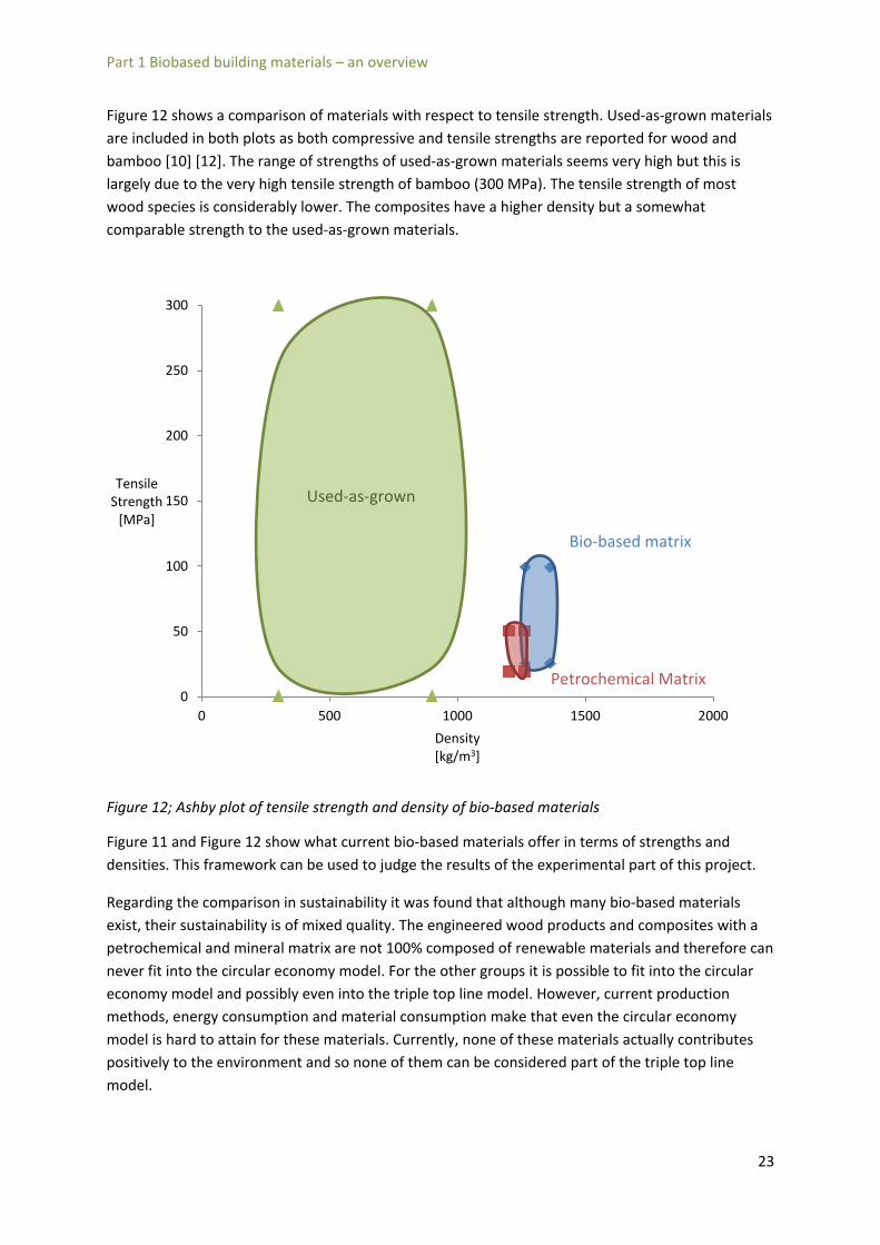
Figure 12 shows a comparison of materials with respect to tensile strength. Used-as-grown materials are included in both plots as both compressive and tensile strengths are reported for wood and bamboo [10] [12]. The range of strengths of used-as-grown materials seems very high but this is largely due to the very high tensile strength of bamboo (300 MPa). The tensile strength of most wood species is considerably lower. The composites have a higher density but a somewhat comparable strength to the used-as-grown materials.
Figure 12; Ashby plot of tensile strength and density of bio-based materials
Figure 11 and Figure 12 show what current bio-based materials offer in terms of strengths and densities. This framework can be used to judge the results of the experimental part of this project.
Regarding the comparison in sustainability it was found that although many bio-based materials exist, their sustainability is of mixed quality. The engineered wood products and composites with a petrochemical and mineral matrix are not 100% composed of renewable materials and therefore can never fit into the circular economy model. For the other groups it is possible to fit into the circular economy model and possibly even into the triple top line model. However, current production methods, energy consumption and material consumption make that even the circular economy model is hard to attain for these materials. Currently, none of these materials actually contributes positively to the environment and so none of them can be considered part of the triple top line model.
0
50
100
150
200
250
300
0 500 1000 1500 2000
Tensile Strength
[MPa]
Density [kg/m3]
Used-as-grown
BiobaseBio-based matrix
Petrochemical Matrix
23

Part 1 Biobased building materials – an overview
Mycelium materials on the other hand consist completely out of renewable materials and require very little energy to be processed. They are therefore definitely part of the circular economy model. Fungi have the remarkable ability to feed on almost anything including plastics and almost all agricultural waste products [33]. Mycelium-materials therefore have the potential to actually absorb non-compostable waste streams and transform them into reusable materials and introduce them into the cradle-to-cradle lifecycle. After use the mycelium materials can either naturally decompose or be used as feed for new mycelium-based products. If a waste stream is absorbed, each cycle will actually make the environment cleaner. Therefore mycelium-based materials can be considered part of the triple-top-line model.
Figure 13; mycelium-based materials in the field of bio-based materials
24

Part 2 Mycelium materials – a fully biobased composite
Part 2 Mycelium materials – a fully biobased composite
2.1 Introduction The aim of this part is to provide a clear insight into the production, properties and performance of mycelium-materials. First, a general characterization of fungi will be given, which will be used to select a group of fungi that are preferential for making mycelium-based materials.
Secondly an overview of production methods will be given. Per step in the production process, key-factors and methods will be discussed.
The section will end with the selection of fungi and substrates that will be used for the experimental samples that will be tested as part of this project.
2.2 Fungi- selection and characterization The fact that fungi are living organisms means they are subject to classification in the biological system. The systematic organization and categorization of organisms is known as taxonomy and a group of similar organisms is called a “taxon”. Although historically organisms were categorized based on similar appearance (phenetics), modern biologists classify organisms based on similar DNA (phylogenetics). Living organism are classified in three main taxa; bacteria, archaea and eucaryota. Fungi, like humans, are a member of the eucaryota.
Figure 14; Phylogeny of life
The fungi taxon is both vast and highly diversified and can be further divided into many subtaxa. Of all these taxa only two are interesting for creating mycelium materials; the Ascomycota and Basidiomycota. Together these fungi are often denoted as the Dikarya or ‘higher fungi’ as they are capable of far larger and more complex organic structures than other fungi. This ability to create
25

Part 2 Mycelium materials – a fully biobased composite
larger structures is important for creating mycelium-based materials as it offers a more robust mycelium and a faster colonization of the substrate.
Figure 15 Phylogeny of fungi according to [34]. The Dikarya group is usable for mycelium-based materials.
The Basidiomycota have two important characteristics that make them preferential for creating mycelium-based materials [35]; Septa and Anastomosis.
Septa are special transverse cell walls with an opening that can be closed. When a normal hypha is ruptured the over pressured cytoplasma will drain through the rupture causing substantial damage and a large loss of nutrients for the fungal colony. However if a septum is present the ruptured hypha can be closed off and only the cytoplasma between two septa will be drained. This significantly decreases the damage caused to the colony by a rupture. Septa are an important characteristic for mycelium-based materials as they greatly increase the robustness of the mycelium. The added protection of septa is only applicable during the growing phase of the mycelium, as the mycelium is alive only in that phase. However as this growing phase can be subject to mechanical action or constant pressure, the added protection of the septa can lead to a faster colonization of the substrate.
26

Part 2 Mycelium materials – a fully biobased composite
Figure 16; Septa are transverse cell walls in Basidiomycota
The second important characteristic is Anastomosis. Anastomosis is the ability of two different hyphae to fuse together when they meet. Anastomosis is crucial to creating a fast growing mycelium as it allows the creation of large networks. Larger networks mean that nutrients can be transported from areas high in nutrients to areas low in nutrients. This allows a more homogeneous growth of the colony in all directions and thus a more homogenous and faster colonization of the substrate.
Another benefit of anastomosis is that it creates a stronger mycelium. As all the hypha are interlinked the resulting mass is much more coherent and able to spread stresses much more efficiently than a mycelium without anastomosis. [35]
Figure 17; Anastomosis is the ability of two meeting hypha to fuse together [35]
Anostomosis and Septa make the Basidiomycota the most logical taxon for creating mycelium-materials. This makes it important to understand the basidiomycete life cycle in order to cultivate fungi for making mycelium materials:
The Basidiomycotus starts as a spore in soil, (dead) wood, or debris such as dead leaves. The spore starts to grow apically (at the tip) into long tube-like structures called hyphae. Such hyphae have a diameter of 5-15 μm. [36]The hyphae form dense networks through the soil or wood in order to find food and other networks of hyphae. Such a network is called a mycelium. When two mycelia meet,
27

Part 2 Mycelium materials – a fully biobased composite
the cells can fuse together through anastomosis, creating a larger, stronger organism. When the organism has grown sufficiently strong and has reached certain conditions depending on the organism, it will start to create fruiting bodies. It does this by creating denser networks of special inflatable cells at a point where it has reached a free surface. These special cells are called primordia. The process of creating primordia is called “pinning”. When the primordia are completely developed and again the right environmental parameters such as humidity and temperature are present, the cells grow rapidly by inflating them with water that can be quickly drawn from a large area by the extensive network of hyphae. The primordia develop into the fruiting bodies of the basidiomycete; the mushrooms. In this sense mushrooms are to fungi what apples are to apple trees. The mushroom is usually shaped as a high pillar with a cap on top. The cap carries new spores that will periodically be released to be dispersed by air flow to new locations. The height of the mushroom ensures that the spores are dispersed over a larger area. The spores that land in suitable habitats will start producing mycelia of their own, completing the basidiomycete life cycle.
Figure 18; Basidiomycete life cycle
2.3 Overview of growing methods Basidiomycota are predominantly only agriculturally cultivated for their mushrooms. Therefore it is from the mushroom industry that we can learn how to cultivate a mycelium. The pinning process however needs to be prevented. For a mycelium-based material it is better to let the organism focus on creating a strong mycelium than letting it waste its nutrients on creating biologically expensive fruiting bodies. The process to cultivate mycelia consists of four steps and to make mycelium-based materials another three steps are required [37]. The process is shown in Figure 19. The first step involves the creation of a habitat for the fungus; the substrate. The substrate can be any cellulose-rich material such as straw, wood and hemp. The needed composition of the substrate differs per fungus but also the goal for which the fungus is cultivated is important. If bulk mushroom harvest is the goal, a cheap but nutritious substrate, like straw, is preferable. If the fungus is bred for genetical
28

Part 2 Mycelium materials – a fully biobased composite
research in a biological laboratory a very clean and controllable substrate like a sugar solution is better.
Once the substrate has been selected and mixed, the substrate needs to be sterilized to prevent other malicious organisms from competing with the fungus during growth. There are several methods to do this and these will be discussed in greater detail in section 2.3.1.
After sterilization the substrate can be inoculated with the spawn of the desired fungus. Preferably pre-grown spawn is used that is cultivated by specialist companies that work under specific conditions to create very pure and reliable spawn.
After inoculation the fourth step, which is the final step for mycelium production, begins. The fungus must now colonize the substrate by growing through it. In this step it is important to provide the correct growing conditions, which once again differ per species and depend on the goals of the cultivation. The growing methods and conditions will be further discussed in section 2.3.2.
To make a mycelium material out of the colonized substrate, the growing needs to be stopped. This is important as elsewise the fungus would still be alive and would ultimately consume the entire substrate or start to produce fruiting bodies. The termination of the growing phase of the mycelium can be done by heating it. When the growing has stopped the sample can be demoulded. To improve the properties of the material a coating might be added as a last step.
Figure 19; SADT-scheme of making mycelium materials
29

Part 2 Mycelium materials – a fully biobased composite
2.3.1 Pretreating the substrate - sterile or just really clean? Usually a substrate is inhabited by many organisms such as bacteria, insects or other fungi that will compete with the desired fungus, inhibiting its growth. Therefore it is important to clean the substrate beforehand. There are four methods to do this: sterilization, pasteurization, hydrogen-peroxide treatment and natural composting.
Sterilization is the most drastic treatment. To sterilize a substrate it needs to be heated to a temperature of 123 ˚C and a pressure of 100 kPa (1 bar) for 20 minutes. The advantage of this treatment is that it kills all organisms and one is ensured that the substrate is completely inert. The downside is that this treatment requires a great deal of energy and specialized equipment, such as pressure cookers or autoclaves. Furthermore, some micro-organisms actually help basidiomycetes in their growth [38] and it might be harmful to depose of them. Sterilizing is generally not a prerequisite to cultivate most fungi but can be used if one needs to be absolutely certain to create an inert substrate. [39]
Pasteurization involves heating the substrate to 60-80 ˚C for 60 min. At this temperature most harmful organisms will die, while the helpful organisms survive. Although less secure then sterilization, pasteurization is easier to perform, costs less energy and will not kill helpful micro-organisms. [40]
Killing the harmful organisms can also be done by treating the substrate with chemicals. Hydrogen-Peroxide (H2O2) is a chemical that damages all organisms in a substrate, but is more damaging to harmful micro-organisms than to the mycelium of a fungus. Immersing the substrate in a 0.3 % Hydrogen-Peroxide solution will be enough to keep the harmful organisms away, while the mycelium can still colonize the substrate. The benefits of this method are that it is much simpler, requires no energy and no equipment other than a mixing container. Also hydrogen-peroxide is not toxic to humans. The biggest advantage however is that after the treatment, the substrate remains protected. When using heat, the substrate will simply cool down and be susceptible to reentry of malicious organisms. With hydrogen-peroxide treatment, the chemicals remain in the substrate and provide ongoing protection against new organisms. The downside is that the hydrogen-peroxide damages the mycelium less than the micro-organisms but it still damages it. Therefore growth of the mycelium will be slower compared to other methods.
The fourth and final method of pretreating the substrate is natural composting. This method is used by industrial companies that create substrate at a large scale. To use this method the substrate needs to partly consist of manure. The substrate is thoroughly mixed and then placed in a closed space. Through natural composting the temperature increases significantly, up to 90 ˚C. Also, toxic gases, such as ammonia, build up in high concentrations. These conditions are aggressive enough to kill the malicious organisms without additional treatment. Advantages of this method are that no treatment other than mixing the substrate is required and that the environment gets so toxic that the waxy outer layer that protects most plants from fungi is weakened or even completely destroyed. This will, later on in the process, make it easier for the mycelium to penetrate the substrate. The disadvantages of this treatment are that manure must be used as part of the substrate and that toxic gases are created during composting. These toxic gases are hazardous to the environment, make processing more difficult to control and require extra safety measures for
30

Part 2 Mycelium materials – a fully biobased composite
employees. Another disadvantage is that if manure is used, the substrate will have the legal status of fertilizer. This puts extra restrictions on transportation and outdoor use.
2.3.2 Open or closed growing – a question of scale After pretreating the substrate, inoculation with pre-grown spawn follows. After the inoculation, the substrate needs to be placed in a controlled environment where the optimal growing conditions can be created and maintained. The optimal conditions vary for each species but for most wood-inhabiting basidiomycota the conditions are:
Growing conditions
Humidity 90-100% (moist to the touch)
CO2 High
Light None
O2 Necessary for growth
Temperature < 30 ˚C (heat is produced during growth)
Table 10; growing conditions for mycelia according to Maurizio Montalti [37]
Growing conditions
Humidity 55%
pH 5.5
Duration of growth 21 days
Urea 1.5-3%
Turning frequency once, at mid-incubation
Superphosphate 1%
Temperature 30 ˚C
Table 11; Growing conditions for C. Versicolor according to Yadav et al [41]
High humidity and a medium temperature are required as these are the natural conditions in which wood-inhabiting fungi grow. The fungus also needs oxygen and produces carbon-dioxide during its growth. Light and carbon-dioxide concentration are a special condition as they act as signifiers to start pinning. Pinning is the process where the fungus creates the primordia on its surfaces that will later grow into mushrooms. Wood-inhabiting mushrooms only pin when they reach a free surface so that mushrooms can grow in the open to improve the dispersion of spores. The fungus knows it reaches a free surface when it senses light. Also, inside the wood the carbon-dioxide that is produced during growth can’t escape freely and therefore there is a high concentration of CO2.
31

Part 2 Mycelium materials – a fully biobased composite
When the fungus reaches a free surface, the CO2 concentration will drop significantly which is another trigger for the fungus to start pinning. [39]
Growing conditions are usually determined to optimize fruiting body production. However when cultivating fungi solely for their mycelium, it is better to prevent the spawning of mushrooms. The fungus can then focus its resources on growing a dense and homogenous mycelium instead of growing biologically expensive fruiting bodies. To prevent pinning, light needs to be kept to a minimum and the CO2 concentration needs to be high.
When trying to create these conditions two possible methods can be used; open or closed growing. In open growth the inoculated substrate is deposited in a large space. This space is then carefully ventilated and moisturized to keep it at the optimal growing conditions. Open growth is typically used by large industrial companies that create mycelium in bulk.
Closed growing involves putting the inoculated substrate in closed containers, often plastic bags. The substrate usually contains enough moisture from the pretreatment to reach the required humidity. The ventilation of CO2 is usually obtained by using bags with filters that allow the passage of gasses. However these filters were developed for mushroom growing. When growing the fungus for its mycelium these filters might not be needed. The oxygen already present in the substrate might be enough to allow the fungus to fully colonize the bag and the CO2 needn’t be ventilated as pinning is not required. Closed growing is mostly used by home-growers or smaller scale growers of exotic species.
Figure 20; pinning conditions
Figure 21; open mycelium growing Figure 22; closed mycelium growing in bags 32
Part 2 Mycelium materials – a fully biobased composite
Whether to choose open- or closed growing depends on the scale of production. Open growing is recommended for large scale, bulk production while closed growing is more suited for production of smaller batches.
2.4 Composition of mycelium-based materials A mycelium material consists of two components; fungus and substrate. In this section the selection of both the fungus and the substrate that will be used in the experimental samples will be addressed.
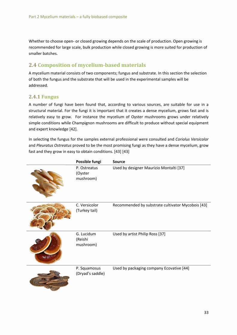
2.4.1 Fungus A number of fungi have been found that, according to various sources, are suitable for use in a structural material. For the fungi it is important that it creates a dense mycelium, grows fast and is relatively easy to grow. For instance the mycelium of Oyster mushrooms grows under relatively simple conditions while Champignon mushrooms are difficult to produce without special equipment and expert knowledge [42].
In selecting the fungus for the samples external professional were consulted and Coriolus Versicolor and Pleuratus Ostreatus proved to be the most promising fungi as they have a dense mycelium, grow fast and they grow in easy to obtain conditions. [43] [43]
Possible fungi Source
P. Ostreatus (Oyster mushroom)
Used by designer Maurizio Montalti [37]
C. Versicolor (Turkey tail)
Recommended by substrate cultivator Mycobois [43]
G. Lucidum (Reishi mushroom)
Used by artist Philip Ross [37]
P. Squamosus (Dryad’s saddle)
Used by packaging company Ecovative [44]
33

Part 2 Mycelium materials – a fully biobased composite
2.4.2 Fiber When selecting the substrate a few factors are important. First the substrate needs to have high cellulose content. The nutrition of a fungus consists of glucose. A fundamental difference between fungi and other organisms is that fungi can break cellulose down into glucose. This means that in cellulose-rich environments fungi can grow rapidly, whilst other organisms cannot. Therefore it is practical to use cellulose-rich materials when growing fungi to prevent contamination by other organisms. Another advantage of using cellulose-rich materials is that in most agricultural crops, cellulose is present as a structural compound. [39]
Secondly it needs to be locally available. It would be counterproductive to create a fully biobased and sustainable material that needs to be shipped large distances while similar solutions are locally available.
Thirdly it needs to be compatible with fungi. Some plants have special compounds to prevent the growth of fungi inside them. Other plants, such as hemp have a natural anti-infectant waxlayer that makes them less susceptible to malicious micro-organism and lowers the need for sterilization [38].
Hemp fiber is a plant that meets all three criteria. Its cellulose content is high, it is common to Northern Europe and research has shown that fungi adhere well to hemp fibers. [45]
Tensile Strength (MPa)
Tensile strain to failure (%)
Young's modulus (GPa)
Density (g/cm3)
Cellulose
(wt %)
Hemicellulose (wt %)
Lignin (wt%)
Waxes
(wt %)
Source
690 1,6 70 1,48 68 15 10 0.8 [19]
550-900 1,6 70 1,48 [24]
660 ± 83 24 ± 8,5 [26]
2140(504) 1,8(0,7) 143,2(26,7) [27]
Table 12; composition and mechanical performance of Hemp fiber according to various sources. Values in brackets are standard deviations.
34

Part 3 Composite material models
Part 3 Composite material models
3.1 Introduction The aim of this project is to investigate the potential of mycelium-based materials for structural use. For such an application the mechanical performance, strength and stiffness, of the material are important.
This section seeks to provide an insight into and a prediction of the mechanical performance of mycelium-based materials. This is done by first considering several model types to describe these materials. The selected model will then be used to describe several key issues for mechanical behavior. The section ends with an indicative calculation using this model.
3.2 Material model choice Mycelium-based materials are new materials for which to date no analytical model exists. However, models for other materials or from different disciplines might be able to describe mycelium-material behavior. The aim of this section is to list several existing models and investigate their usefulness to mycelium-based materials.
3.2.1 Soil Mechanics approach The first model considered is the soil mechanics model. The aim of soil mechanics is to predict the strength, stiffness and long-term behavior of large soil masses that consist of sand, clay, peat and water. In relation to mycelium-based materials this approach has two main advantages. Firstly, it allows the modeling of more than one material. Mycelium-based materials will always consist of the mycelium combined with at least one other material as a substrate so the inclusion of several materials will make the model more accurate. Secondly, as soil is often saturated with water, the impact of the water pressure on the mechanical properties is included in soil mechanics models. This is reflected in Terzaghi’s law, in which the soil stress is related to the water pressure: ' pσ σ= + [46]
Where: σ = total stress σ’= effective stress p = water pressure Mycelium-based materials can best be grown in environments with high water concentration, perhaps even saturation. Consequently, a soil mechanics approach can be helpful in describing mycelium-based materials. An important note here is that the mycelium will be dried after growth to kill the fungus. This drying process will lower the water content significantly. The impact of the water content on the strength and stiffness will therefore also be lowered.
35

Part 3 Composite material models
A disadvantage of the soil mechanics approach is that these theories have been created for very large bodies of soil, several meters to hundreds of meter wide and long. Mycelium-materials are limited in their size due to growing conditions. The theories of soil-mechanics are not be applicable to such small bodies because local stress concentrations can no longer be evened out. Another downside of soil mechanics is that it generally only deals with compression as a load. Mycelium-materials can resist tension as well and will therefore behave differently than soil.
Figure 23; a typical three-phase model for soil
3.2.2 The generally orthotropic model – the wood approach Wood is a traditional construction material and is thoroughly and expansively described in scientific literature. Though wood has a complicated micro structure, at the macro level a simple orthotropic linear elastic material model is used. This means that the material is considered to behave linear elastically up to a failure stress (the strength) and that different strengths are used for loading along the fiber direction and loading perpendicular to it.
Figure 24; the material model used for wood is a linear-elastic orthotropic material.
There are several advantages of the wood approach for mycelium-based materials. Such materials will also be orthotropic as the natural fibers from which they are created also exhibit strong differences in longitudinal and transversal strength and stiffness. Another advantage is that the approach is relatively simple to use as all local phenomena are summed and evened out to create simple and usable macro-properties such as the Young’s modulus, E, and the characteristic compression strength, fck.
36

Part 3 Composite material models
The wood approach though, does not allow for the interaction of more than one material. As mycelium-based materials will consists of at least two materials this is a large disadvantage. Using the wood model therefore would not allow predicting the effect of changing the composition of the substrate.
3.2.3 Composite approach A composite is a union of two or more materials to improve the properties of the individual materials. In the context of this report this definition will be narrowed to composites that consist of fibers imbedded in a matrix. In such a material the usually high strength and stiffness of the fiber can be efficiently used by cooperating with the ductile and formable matrix.
Mechanical models for such composites have the aim to predict the influence of the fiber or matrix on behavior of the composite as a whole. For instance models can be developed that relate the volume fraction of fibers to the axial stiffness of the composite. The most basic models can be derived for uniaxial continuous fibers in a thin layer, called a lamina.
Figure 25; Different fiber reinforced composite types
Composite models offer the greatest freedom for describing mycelium-based materials as they both include the interaction of different materials (fiber and matrix) and allow for differences in longitudinal and transversal strength and stiffnesses. In fact, the model used for wood can be considered as a special case of composite model where the fiber and matrix properties are summed into one composite property and only fiber direction is accounted for.
Another advantage for using composite models is that the natural fibers which will be used in creating mycelium-materials are currently applied in composites with a (bio) plastic as matrix. Such natural fiber-plastic materials are described using composite models. Therefore the fiber properties needed for use of composite models are already known and there is experience in using composite models on such fibers.
The downside of the composite model is that it is more complicated than the wood model. More possibilities are allowed and this leads to more complicated equations. Another problem is that the accuracy of composite models is highly sensitive to the process precision. The process of making mycelium-based materials is new and therefore not yet highly controlled. The effect of this imprecision will have to be accounted for when using composite models.
37

Part 3 Composite material models
Composite models offer the greatest value for mycelium-materials as they include more variables than the wood-model and are more applicable than the soil-mechanics models. Furthermore the field of composites is broad and highly advanced. Included are theories that describe the hygrothermal and viscoelastic behavior of composites. This ensures that a composite model for mycelium-based materials can depend on a sound base of scientific literature and has the potential to be expanded for advanced effects in later studies.
This chapter will continue with the derivation of a composite model for mycelium-based materials. The aim is to derive a model that consists of aligned fibers in a continuous matrix, with an expansion to include the effect of short-fibers. To arrive at such a model, three steps need to be taken:
i. set up relations between uniaxial and rotated compliance matrices ii. set up relation between matrix- and fiber properties and the composite properties iii. allow for the use of short fibers
These steps will be executed in the next paragraphs.
3.3 Rotated compliance matrix In this section the rotation matrix to rotate a compliance matrix from one coordinate system to another is derived. For simplicity reasons, the derivation made here will be in 2d but the same principles apply to a 3d derivation.
Consider a differential object in an x,y coordinate system. The stress vectors that apply to such a differential object are shown in Figure 26. Only positive stresses are shown. From elementary mechanics it is known that the compliance matrix for such an object is:
11 12
21 22
33
00
0 0 2 / 2
x x
y y
xy xy
Q QQ Q
Q
σ εσ ετ γ
=
[2.1]
Figure 26; differential object in a x,y and 1,2 coordinate system
A second 1,2 coordinate system is introduced that shares the origin of the x,y system but is rotated by an angle θ. Consider a single face of the rotated differential element with a surface dA. With simple goniometry it can be shown that:
38

Part 3 Composite material models
cos
siny
x
dA dAdA dA
θ
θ
=
= [2.2]
Figure 27; single face of a rotated differential element
A stress vector p, that is not aligned with any axis, is applied to the face in the 1,2 plane. The resulting stresses on the differential element are shown in Figure 28.
Figure 28; stress vectors on rotated differential element
Equilibrium of forces can now be stated in both x- and y-directions:
1 12
1 12
cos sin cos sin 0
sin cos sin cos 0x x xy
y y xy
F dA dA dA dA
F dA dA dA dA
θσ θσ σ θ τ θ
θσ θσ σ θ τ θ
= − − − =
= + − − =∑∑
[2.3]
The surfaces dA can be cancelled from these equations. The results are two equations which can be solved simultaneously to yield:
( ) ( )2 2
1
2 212
cos sin 2 sin cos
sin cos cos sinx y xy
y x xy
σ σ θ σ θ τ θ θ
τ σ σ θ θ τ θ θ
= + +
= − + − [2.4]
39

Part 3 Composite material models
An expression for σ2 can be found by evaluating the first of equations [2.4] at θ = θ+90˚.
2 22 sin cos 2 sin cosx y xyσ σ θ σ θ τ θ θ= + − [2.5]
This results in a set of equations that can be set in matrix-vector format:
[ ]2 2
12 2
22 2
12
22
x x
y y
xy xy
c s css c cs Tcs cs c s
σ σ σσ σ στ τ τ
= − =
− −
[2.6]
Where c = cos θ s = sin θ [T] is the transformation matrix.
In similar fashion it can be shown that the transformation matrix [T] can also be used to relate the strains of different axes to each other:
[ ]1
2
12
x
y
xy
Tε εε εγ γ
=
[2.7]
Or in inverse form:
[ ]1
12
12
x
y
xy
Tε εε εγ γ
−
=
[2.8]
Equation [2.6] can be used together with [2.1] to yield:
[ ][ ]1
2
12 / 2
x
y
xy
T Qσ εσ ετ γ
=
[2.9]
Equations [2.9] and [2.7] can be combined to give:
[ ][ ][ ]1 1 1
12 2 2
12 12 12
T Q T Qσ ε εσ ε ετ γ γ
− = =
[2.10]
The components of these matrices can be multiplied to yield expressions that relate the stiffness of one coordinate system to the other. To indicate that the compliance is rotated, an overbar is applied. The relations between [Q] and [ Q ] are expanded below:
40

Part 3 Composite material models
( )4 4 2 2
11 22 12 6611
2 2 4 411 22 66 1212
4 4 2 211 22 12 6622
3 311 12 66 22 12 6616
3 311 12 66 22 12 6626
2 211 22 12 6666
2( 2 )
( 4 )
2( 2 )
( 2 ) ( 2 )
( 2 ) ( 2 )
( 2 2 )
Q Q c Q s Q Q s c
Q Q Q Q s c Q s c
Q Q s Q c Q Q s c
Q Q Q Q sc Q Q Q cs
Q Q Q Q cs Q Q Q sc
Q Q Q Q Q s c Q
= + + +
= + − + +
= + + +
= − − − − −
= − − − − −
= + − − + ( )4 466 s c+
[2.11]
Using these relations the effect of rotation on the axial stiffness can be plotted. The following assumptions, which are common for composite materials, are used:
i. E1 >> E2 (In this example, E1 = 10E2) ii. v12 = 0,3
iii. v21 =v12(E1/E2) iv. G12 = E2/2
Graph 1; effect of rotation on axial stiffness
From Graph 1 it can be concluded that a relatively small increase in rotation leads to a high loss of stiffness. In the next section it will be proved that axial stiffness is mostly dependent on the fiber. Combining these two conclusions leads to the statement that fiber orientation has high effect on overall composite stiffness.
0
2
4
6
8
10
12
0 10 20 30 40 50 60 70 80 90
Ex/E2
θ(˚)
41

Part 3 Composite material models
3.4 Composite stiffness In engineering composites, it is important to understand the effect fibers and matrix have on the strength and stiffness of the composite. In this section such relations are derived for a single orthotropic continuous fiber-reinforced lamina. Although such models are highly abstract and are not very useful in practice, they form the basis for more complicated models that include fiber length and more advanced effects.
The derivation starts with a relative volume element (RVE) that consists of a square fiber inside a square block of matrix, see Figure 29. Although most fibers are round, a square fiber is acceptable here as only fiber surface is included in the equations. Circular surfaces can easily be related to square surfaces if needed.
Figure 29: RVE of square fiber in a rectangular matrix
Furthermore three assumptions are made considering the materials:
i. The matrix is isotropic Em1=Em2=Em ii. The fiber is orthotropic Ef1=Ef2 iii. Fiber-matrix bonding is not perfect. This results in a different stress distribution as in:
1 1 1
1 1 1
f c
m c
ab
σ σ
σ σ
=
= [3.1]
Where c,f and m denote composite, fiber and matrix respectively. The 1 signifies the longitudinal direction and a 2 denotes transversal direction. The stress state is evaluated by stating that total strain energy in the composite equals the sum of the strain energies stored in the fiber and matrix:
21 1 1 1
21 1 1 1
21 1 1
1 12 2
1 12 2
1 12 2
c
f
m
c f m
c c c c cV
f f f f f fV
m m m m m mV
U U U
U dV E V
U dV E V
U dV E V
σ ε ε
σ ε ε
σ ε ε
= +
= =
= =
= =
∫
∫
∫
[3.2]
42

Part 3 Composite material models
With an isotropic matrix, an orthotropic fiber and the assumption that Poisson strains are neglected, Hooke’s law holds:
1 1 1
1 1 1
1 1
c c
f f f
m m m
EEE
σ εσ ε
σ ε
==
=
[3.3]
Combining [3.2] and [3.3] leads to:
2 2 21 1 1 1 1
1 1 1 1 1
c f f f m m m
c c f f f m m m
E E v E vv v
ε ε ε
σ ε σ ε σ ε
= +
= +[3.4]
This can be combined with [3.1] to yield:
1 1 1 1 1 1 1 1c c c f f c m ma v b vσ ε σ ε σ ε= + [3.5]
The composite stresses can be cancelled out from this equation. Using Hooke’s law again, [3.5] can be reduced to:
11 11 1
1 1
fc mf m
f m
a v b vE E E
σσ σ= + [3.5]
Relation [3.1] is also used again to gain:
1 1
2 2
1 1
1 f m
f m
v va bE E E
= + [3.6a]
Recall that due to assumption iii at the start of this derivation no perfect bonding was assumed leading to equation [3.6a]. If perfect bonding is assumed, the fiber, matrix and composite stresses will be equal and a1 and b1 will be equal to unity. Relation [3.5] will simply revert to:
1 1f f m mE E v E v= + [3.6b]
Relation [3.6b] is called the ‘rule of mixtures’. In many cases the assumption of perfect bonding is justified, especially in the longitudinal fiber direction. However, in situations where little is known about a material, equation [3.6] allows the assumption to be tested. In this case, extra experiments will have to be executed to be able to calculate a1 and b1. If both factors are known, the assumption of perfect bonding can be tested. If a1 and b1 approach unity, the rule of mixtures will become valid.
In the transverse direction, the derivation for the modified rule of mixtures is analogous. Only here a differing strain distribution is used instead of a stress distribution as shown in [3.1].
2 2 2
2 2 2
f c
m c
ab
ε ε
ε ε
=
= [3.7]
This leads using equations analogous to [3.2] and [3.4] to:
43

Part 3 Composite material models
2 22 2 2 2f f m mE a E v b E v= + [3.8]
If perfect bonding is assumed the rule of mixtures for transverse moduli is obtained:
2 2
1 f m
f m
v vE E E
= + [3.9]
44

Part 3 Composite material models
3.5 Short fiber adaptations The previously derived models for strength and stiffness of composite materials are based on the assumption of unidirectional fibers that span the entire length of the composite. Although such composites provide the greatest performance in terms of strength and stiffness, it also takes very high precision and very specific materials and equipment to make them. For instance, the aerospace industry, which requires high performance, makes use of such precisely engineered composites.
In many other applications however, fibers are either shorter than the composite, are randomly oriented, or both. Models exist for random orientation of fibers but are highly theoretical, mathematically complex and difficult to handle. Therefore this section will only expand the rule of mixtures to allow for fibers of differing lengths. However, these models require input that is very hard to procure by experiments. Therefore the short-fiber will only be used to set a safe limit for using the simple rule of mixtures of section 3.4.
The derivation of the short-fiber expansion starts with a new RVE of a short circular fiber inside a circular piece of matrix material on which a longitudinal stress is applied.
Considering equilibrium of the RVE yields:
( )2 2
04 4
4
x f f f
f
a aF d a dx
ddx a
π πσ σ σ τπ
στ
= + − − ⋅ =
=
∑ [4.1]
Figure 30; RVE for a short fiber in a circular matrix with longitudinal stress applied
45

Part 3 Composite material models
Expression [4.1] states that the increment in fiber stress over dx equals the shear stress at the matrix-fiber interface. The equation can be rearranged and then integrated over the entire length x to give:
0 0
4f x
fd dxa
σ
σ
σ τ=∫ ∫ [4.2]
Most of the longitudinal stress is transferred from fiber to matrix by interfacial shear stresses. It is therefore safe to assume that the stress transfer by longitudinal stress at the ends is negligible. Therefore σ0=0. Considering the shear stress, there are two options. If the matrix is considered rigid-plastic, then the shear stress is constant. This approach is known as the Kelly-Tyson model. The other option is to consider the matrix linear-elastic. The shear stress then varies over the shear strain according to the shear modulus: Gm. This was done by Cox. Both the Cox and the Kelly-Tyson models are applicable in different situation. However, for the purposes of this section the much simpler Kelly-Tyson model will be sufficient.
Figure 31; The Kelly-Tyson (left) and the Cox model (Right)
With the assumptions of no longitudinal stress transfer and constant shear stress, equation [4.2] can be solved to give:
4f y x
aσ τ= [4.3]
In which τy is the constant shear stress.
To derive equation [4.3] it has been assumed that the longitudinal stress is zero at the ends of the fiber, x=0 and at x=L. This means the stress distribution should be symmetric about x=L/2. The distribution should therefore be as shown in Figure 32.
46

Part 3 Composite material models
Figure 32; shear and longitudinal stress distribution along a fiber in the Kelly-Tyson model
The maximum stress occurs at x=L/2. Substituted in equation [4.3] this gives:
max
2 yf
Laτ
σ = [4.4]
This equation would imply that the maximum fiber stress could increase indefinitely as the length increases. The fiber stress is however limited by two factors. First it can never be higher than part of the composite stress applied; secondly it cannot overcome the fiber strength. If equal strains are assumed the relation of fiber stress to composite stress is given by:
1 1 1
11 1 1 1 1
11 1
f f ff
c c f c
c f
EE
EE
σ ε
σ ε σ σε ε
=
= ==
[4.5]
Combining equations [4.4] and [4.5] gives a relation for the length over which stress transfer is occurring. This length is commonly referred to as the ineffective fiber length (Li) as the maximum stress is not yet developed in this part.
1 1
12f c
iy
E aL
Eστ
= [4.6]
The development of the stress distribution as the fiber length increases to Li and more than LI is shown in Figure 33.
47

Part 3 Composite material models
Figure 33; stress distribution in short fibers in relation to the ineffective length.
As mentioned, the other limiting factor for the fiber stress is the fiber strength. Further increase of the stress is impossible as the fiber would fail. The fiber strength is here denoted as sf1
+, where the plus-sign stands for tension, the f stands for fiber and the 1 stands for longitudinal. Substitution of this limit in equation [4.4] gives a relation for the length at which fiber failure occurs: the critical fiber length, Lc:
1
2f
cy
s aL
τ
+
= [4.7]
In the simple rule of mixtures the assumption is made that all fibers are uniformly stressed along their length. For short fibers this no longer holds. The average stress for fibers such as in Figure 33 a) and b) is then given by:
/2
10
1/ 2
L
f
f
dx
L
σσ =
∫ [4.8]
From the same figure, it can be seen that the stress varies linearly over the length as given by:
max1 / 2
ff
i
xLσ
σ = [4.9]
Using this relation to evaluate the integral of [4.8] yields:
/2 /2max
1max0 0
1/ 2
/ 2 / 2 2
L Lf
ffi
f
i
xdx dx
LLL L L
σσ
σσ = = =
∫ ∫ [4.10]
This relation can be used in the equation for composite stress:
1 1c f f m mv vσ σ σ= + [4.11]
If we assume composite failure by fiber failure, the following assumptions hold:
48

Part 3 Composite material models
1
1
1
fmax f
c L
m mf
i c
sss
L L
σσσ
+
+
+
====
Substituting these assumptions in [4.11] and combining with [4.10] and [4.9] gives:
1
1 1
1 1
2
f
L f f mf mc
yL f f mf m
Ls s v s vL
Ls s v s v
s aτ
+ + +
+ + ++
= + = +
for L < Lc [4.12]
For the situation in Figure 33 c), where L>Li, relation [4.9-4.10] can be derived in similar fashion to yield:
1
1 1
1 1
12
14
f
cL f f mf m
L f f mf my
Ls s v s vL
s as s v s v
Lτ
+ + +
++ + +
= − + = − +
for L > Lc [4.13]
Equations [4.12] and [4.13] are modified versions of the rule of mixtures to include the effect of short fibers. In both equations a term is added to increase or decrease the fiber stress. As stated in the introduction of this paragraph, it is neither useful nor possible to use these equations directly as three variables are unknown, hard or laborious to acquire by experiments. These are the fiber length L, fiber diameter a and the interfacial shear stress τy. The interfacial shear stress is very hard to derive from experiments. It would also be extremely laborious and difficult to measure the length and diameter of every fiber.
However relations [4.12] and [4.13] are very much alike the simple rule of mixtures. The only difference is the term in front of the fiber contribution. Let’s name this term the correcting term as it corrects the simple rule of mixtures for fiber lengths.
11 , 14 2
f c
y
s a LL Lτ
+ − − = Correcting term
However, if the correcting terms start tending to unity, it will be safely accurate to use the simple rule of mixtures. Therefore equations [4.12] and [4.13] will be used to calculate a minimum length Lmin that is needed to safely use the rule of mixtures. Several assumptions are made to make this possible:
An accuracy α is introduced. The correcting term for short fibers is equaled to the accuracy. The closer α tends to zero, the more accurate the model becomes. An accuracy of 1% is deemed acceptable.
49

Part 3 Composite material models
1
1
min
min
4
4
f
f
y
y
s a
L
s aL
aτ
aτ
+
+
=
=
[4.14]
In this relation Lmin is the minimum length required to safely use the simple rule of mixtures. Relation [4.14] expresses this length in three variables, fiber strength, diameter and the interfacial shear strength.
Of these variables, the diameter might be considered the simplest to derive. However for natural fibers this diameter is very difficult to obtain. Due to the microstructure of natural fibers the cross-section varies along the length. Symington et al [25] embedded fibers in resin, then cut the fibers and polished the surface to allow inspection by microscope. They concluded that most natural fibers can be accurately considered circular or ellipsoidal. Also Park et al [27] and Sawpan et al [28] did measurements of hemp fiber diameters, their results are listed in Table 13.
Fiber diameter [μm] Source Min Max Hemp 25,3 31,5 [28] Hemp 9,26 12,46 [27]
Table 13; hemp fiber diameters
The results show a large spread in diameter. This can be explained by two factors. First of all hemp fibers are a natural product with differing properties per harvest. Secondly, natural fibers consist of bundles of progressively smaller tubes. This structure makes it difficult to define what exactly constitutes a fiber. Bos et al [22] made a study of flax fibers in which they made a clear distinction between the different levels of bundles and defined labels for each level. Using this taxonomy it is likely that Sawpan et al considered hemp fibers at the technical fiber level and that Park et al considered fibers at the elementary fiber level. For the calculation of the minimum length several different diameters will be used.
50

Part 3 Composite material models
Figure 10; Hierarchy of flax bundles as defined by Bos et al [22] [22]
Considering the fiber tensile strength the scale of the fiber is also important. The smaller the bundle tested the higher the tensile strength. Although many researchers have tested the tensile strength of hemp fibers, very few have stated the diameter they used. Considering Park et al [27] worked at the elementary fiber level and that his tensile strength is very high, it is likely that the other sources from Table 14 worked at a fiber bundle or technical fiber level. As the minimum fiber length increases with fiber strength, the minimum fiber strength found (550 MPa) will be used in the calculation.
Tensile Strength (MPa)
Tensile strain to failure (%)
Young's modulus (GPa)
Density (g/cm3)
Source
690 1,6 70 1,48 [19] 550-900 1,6 70 1,48 [24] 660±83 24±8,5 [26]
2140 (504) 1,8(0,7) 143,2(26,7) [27] Table 14; mechanical properties of hemp fibers
The most difficult variable to discern is the interfacial shear strength (IFSS). The IFSS depends not only on the fiber but also on the matrix. Although there are reports of the IFSS of hemp fibers none of those reports are with mycelium as a matrix. However Li et al [26] treated hemp fibers with white-rot fungi (Schizophyllum Commune) before using the fibers in a PP-matrix. The results were that the white-rot treatment led to an increase of IFSS of up to 79%.
51

Part 3 Composite material models
Matrix Fiber IFSS [MPa] Source Min Max PLA Hemp 5,33 11,41 [28] UPE Hemp 9,9 20,3 [28] polypropylene Hemp 3,26 6,69 [26] polypropylene White Rot
treated Hemp 5,84 8,93 [26]
polypropylene-maleic anhydride polypropylene copolymer (PP-MAPP)
Hemp 4,9 6,3 [27]
Soy Protein Concentrate Resin (SPC) Hemp Yarn 18 27 [47] Table 15; Interfacial Shear Strength (IFSS)for different Hemp fiber composites
It is the opinion of the author that the IFSS for hemp with a mycelium will be higher than hemp with a plastic matrix. This is because of a difference in coupling. The coupling between hemp fibers and a plastic matrix is chemical. Often this coupling is very poor because the fiber is hydrophilic and the matrix is hydrophobic. Mycelium bonds itself with its substrate by growing hypha through the substrate. This creates a more mechanical than chemical bond. This type of bonding is no longer dependent on the hydrophilicity of the fiber and is supposed to be much stronger. The calculation of the minimum length will include a range of IFSS’s.
Figure 34; schematic of hypha-fiber bonding
Compiling the gathered data on the three variables leads to Table 16.
Min Max Most unfavorable Fiber tensile strength sf1
+ [MPa] 500 600 600
Fiber diameter a [mm2] 0,000009 0,000031 0,000031
Interfacial shear strength
τy [MPa] 3,26 20,3 3,26
Accuracy α - 0,01 0,01 0,01 Table 16; data for the calculation of the minimum fiber length
Graph 2 shows the effect of IFSS on the minimum fiber length. It seems that even the most unfavorable data lead to a minimum length of 0,4 mm which is very easy to realize in practice. Therefore it is safe to use the simple rule of mixtures for hemp-mycelium composites.
52

Part 3 Composite material models
Graph 2; Minimum fiber length
0
0,05
0,1
0,15
0,2
0,25
0,3
0,35
0,4
0,45
0 5 10 15 20 25
Lmin(mm)
τy (N/mm2)
a = 9μm
a = 31μm
53

Part 4 Experiments
Part 4 Experiments
4.1 Introduction This chapter will describe the experimental part of this project. As no company or institute was available that could be relied upon to supply samples, samples were made by the author. The chapter will start with a description of the materials and methods used to make these samples and then continue with the methods used to test these samples. Finally the results will of these tests will be shown and discussed.
4.2 Method Three sets of samples were made. The first set was made with different fungi, substrates and sterilization methods. The purpose of this set was to provide explorative results on what methods and combination work and what range of strengths and densities to expect.
The combination from the first set that yielded the highest compressive strength was made in larger numbers for the second and third set. The purpose of these sets was to provide a better understanding of the strengths of this particular combination and to inform on the variability of these results.
4.2.1 Materials Tests were performed on samples consisting of mycelium of Coriolus Versicolor and Pleurotus Ostreatus. Substrates were used consisting of wood chips, hemp hurd, loose hemp fiber and non-woven mats of hemp fiber. The mycelium was grown using pre-grown spawn cultivated on rye that was bought at Mycobois. The non-woven hemp mats were kindly provided by HempFlax b.v. The wood chips and hemp hurd were bought at a local pet store.
For the first group a spawn to total weight ratio of 20% was used. For the second and third group a ratio of 10% was used. The first group was given a higher ratio to ensure a faster growth.
4.2.2 Growing Process The worktop, gloves and all other equipment used in this procedure was cleaned with a 95% alcohol solution to prevent contamination of the samples.
The composition of the first group of samples can be found in Table 17. The substrate was sterilized by placing it in boiling water for 100 minutes. Three samples were treated with 0,3 % hydrogen-peroxide solution instead of boiling. After the treatment the substrate was squeezed by hand to drain excess moisture. The substrate was then placed into transparent plastic molds. The substrate was mixed with particles of the spawn.
The molds were closed and then placed in larger boxes that could be closed off. The samples were allowed to grow in dark conditions at room temperature. To ensure a completion of the growth process, a long growth period of 30 days was used.
After the growth period the samples were placed inside an oven at 125 ˚C and dried for 2 hours. The decrease in weight for several samples during the drying procedure can be seen in Figure 35.
54

Part 4 Experiments
Table 17; Overview of samples in group 1
Number Substrate Spawn Sterilization method
1 hemp hurd
C. versicolor
boiling
2 wood chips
C. versicolor
boiling
3 hemp hurd
P. ostreatus
boiling
4 wood chips
P. ostreatus
boiling
5 hemp mat
C. versicolor
boiling
6 hemp fibers
C. versicolor
boiling
7 hemp mat
P. ostreatus
boiling
8 hemp fibers
P. ostreatus
boiling
9 hemp fibers
C. versicolor
H2O2
10 wood chips
C. versicolor
H2O2
55
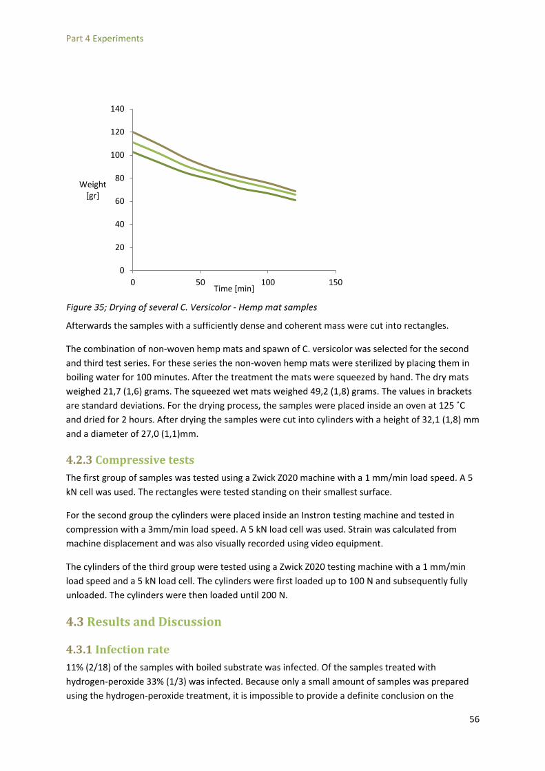
Part 4 Experiments
Afterwards the samples with a sufficiently dense and coherent mass were cut into rectangles.
The combination of non-woven hemp mats and spawn of C. versicolor was selected for the second and third test series. For these series the non-woven hemp mats were sterilized by placing them in boiling water for 100 minutes. After the treatment the mats were squeezed by hand. The dry mats weighed 21,7 (1,6) grams. The squeezed wet mats weighed 49,2 (1,8) grams. The values in brackets are standard deviations. For the drying process, the samples were placed inside an oven at 125 ˚C and dried for 2 hours. After drying the samples were cut into cylinders with a height of 32,1 (1,8) mm and a diameter of 27,0 (1,1)mm.
4.2.3 Compressive tests The first group of samples was tested using a Zwick Z020 machine with a 1 mm/min load speed. A 5 kN cell was used. The rectangles were tested standing on their smallest surface.
For the second group the cylinders were placed inside an Instron testing machine and tested in compression with a 3mm/min load speed. A 5 kN load cell was used. Strain was calculated from machine displacement and was also visually recorded using video equipment.
The cylinders of the third group were tested using a Zwick Z020 testing machine with a 1 mm/min load speed and a 5 kN load cell. The cylinders were first loaded up to 100 N and subsequently fully unloaded. The cylinders were then loaded until 200 N.
4.3 Results and Discussion
4.3.1 Infection rate 11% (2/18) of the samples with boiled substrate was infected. Of the samples treated with hydrogen-peroxide 33% (1/3) was infected. Because only a small amount of samples was prepared using the hydrogen-peroxide treatment, it is impossible to provide a definite conclusion on the
0
20
40
60
80
100
120
140
0 50 100 150
Weight [gr]
Time [min]
Figure 35; Drying of several C. Versicolor - Hemp mat samples
56

Part 4 Experiments
effect of such a treatment. However, visual inspection also showed that mycelial growth in the hydrogen-peroxide treated sample was less dense then the samples with boiled substrates. A possible explanation is that after the treatment, the substrate remains protected. When boiling the substrate, the substrate will simply cool down and be susceptible to reentry of malicious organisms. With hydrogen-peroxide treatment, the chemicals remain in the substrate and provide ongoing protection against new organisms. The downside is that the hydrogen-peroxide still damages the mycelium albeit not as severe as the other micro-organisms. Therefore growth of the mycelium will be slower compared to other methods.
4.3.2 Visual inspection of growth All samples showed a strong gradient in mycelial density over the height, with stronger concentrations of mycelium at the interfaces. The concentration was also stronger at the top surface than at the bottom. Figure 36 shows a top, bottom and side view of a sample in which it is clearly visible that the top and bottom have a much denser mycelium and that the top is denser than the bottom. Two explanations are possible for this effect. First of all air enters the mold trough the seams of the lid at the top. Therefore a gradient in oxygen concentration develops with most oxygen at the top and least at the bottom. Secondly, mycelium produces heat during its growth. The heat in the center of the mold will be less able to dissipate than the heat at the interfaces. As oxygen stimulates growth and heat deters growth, this would explain why the mycelium is denser at the interfaces and denser at the top. If the thickness of the material is increased, there will be a point at which the center becomes too hot or too anaerobic to allow any growth at all. The implication is that mycelium-materials will have a maximum thickness unless measures are taken to create an even oxygen and temperature distribution.
Figure 36; from top left, going clockwise: top, bottom and side view of a sample of C. Versicolor and non-woven hemp mats.
57
Part 4 Experiments
Regarding the substrates the non-woven hemp mats showed the best compatibility with mycelia as growth could be observed to be much denser. The samples with loose hemp fibers also showed dense colonization but resulted in a mass too incoherent to be used for testing. The hemp hurd samples showed a comparable but slightly less dense growth. The samples with wood chips were markedly less dense and in some cases showed no growth at all. Images of samples are included in Table 17.
The samples with C. Versicolor showed a denser growth than P. Ostreatus in all cases. The combination P. Ostreatus with wood chips resulted in a mass that was too sparsely colonized to be used for testing.
58

Part 4 Experiments
4.3.3 Compressive results The results from the compressive tests of the first group can be seen in Figure 37. After a small linear path, a definite top in stress can be observed. Both the stiffness and the top of the specimens with hemp mats are higher than the specimens with wood chips. Of the specimens with hemp mats, the specimens with C. versicolor show a higher strength and stiffness then the P. ostreatus samples. Some literature has reported on a specifically good compatibility between hemp fibers and mycelia [45] [26]. This concurs with the results shown here that samples with hemp mats show a greater strength and stiffness.
The results of the second group can be seen in Figure 38. The stiffness increases exponentially with stress. The stresses at 10% strain are 2,6 - 9,4 kPa. The behavior of the first group differs enormously from the second and third group. This can be explained by two reasons. First of all the specimens from the first test were of rectangular rather than cylindrical shape and also had larger dimensions. This might lead to a form of buckling which would explain the top in Figure 37. The second reason for the difference might be that the rectangular specimens were tested with different orientation of the fibers in the hemp mats with respect to the load direction. This is schematically shown in Figure 39. As composite strength is very dependent of fiber orientation [6] this might explain the relatively high stresses in Figure 37.
0
0,1
0,2
0,3
0 0,1 0,2 0,3 0,4 0,5 0,6
Stress [MPa]
Strain [mm/mm]
Figure 37; Stress-strain graph of the first group of samples
Hemp mat – Versicolor
Hemp mat - Pleurotus
Wood – Versicolor
59

Part 4 Experiments
Figure 40 shows the results of the third group. The stiffness increases markedly when the samples are reloaded. The stress at 10% deformation during the first loading was 18,8 (7,0) kPa and the stress at the same deformation during the second loading was 46,5 (20,2) kPa.
Figure 39; Schematic drawing of the difference in fiber orientation between samples of group 1 and of groups 2 and 3.
0
0,1
0,2
0,3
0,4
0,5
0 0,1 0,2 0,3 0,4 0,5 0,6 0,7 0,8
Stress [MPa]
Strain [mm/mm]
Figure 38; Stress-strain graph of the second series of samples. All samples of the second group consist of non-woven hemp mats and spawn of C. versicolor.
60

Part 4 Experiments
To clarify the effect of two load cycles, a schematized stress-strain graph is shown in Figure 41. The first cycle involves loading the sample up to a force of 100 N, leading to a stress σ1. The stress at 10% strain (ε10%, 1) is taken as the strength and the angle of the axis and the tangent at this point is taken as the stiffness (E1). The samples are then unloaded. A part of the deformation will be recovered and a part will be permanent. The permanent part of the deformation is plastic deformation (wpl) and the part that is recovered is elastic (wel). The elastic deformation was 42% (10%) of the total deformation. The sample is then loaded again up to a load of 200 N concurring with a stress σ2 in Figure 41. Again the stress is measured at 10% strain (ε10%, 2) and the stiffness is taken as the angle between the strain-axis and the tangent at this point (E2). The deformation during the second load cycle was found to be almost completely plastic.
Figure 41; Schematized stress-strain graph of loading Versicolor-Hemp samples in two cycles.
0,00
0,10
0,20
0,30
0,40
0,50
0,0 0,2 0,4 0,6
Stress [MPa]
Strain [mm/mm]
0,00
0,10
0,20
0,30
0,40
0,50
0,0 0,2 0,4 0,6
Stress [MPa]
Strain [mm/mm]
Figure 40; Results of the third group. Samples were first loaded until a load of 100 N was reached (left). Then the load was removed and samples were loaded again until 200 N (right).
61

Part 4 Experiments
A possible explantion for the large increase in stress and stiffness after reloading is that the mycelium-based samples are very porous and contain a great deal of air. In compression this air is pushed out and a much compacter material remains. If the remaining material is then loaded again a much greater resistance can be build up. This hypothesis would also explain that half the deformation of the first load cycle is plastic whilst nearly all deformation of the second load cycle is elastic. This is because once the air is pushed out and a compacter material is created, the air can not return once the load is removed. If this behavior is indeed due to the air content of mycelium-based materials, this would have the important implication that mycelium-based materials can function as insulation materials. This is because high air content predicts a low thermal conductivity. The most important conclusion that can be drawn from these results is that mycelium-based materials created with the substrates, species and substrates used here, do not fit into the Ashby plot in the conclusion of Part 1 (Figure 11). Rather, they should be considered part of another group of materials. Softer, lightweight materials such as damping or insulation materials can be a better group of materials to compare to. Table 18 compares the strengths of several lightweight structural materials with the results of the third group. Though the observed strengths are comparatively low it should be noted that Mycelium-based materials are fully bio-based and fully degradable whereas the other materials in Table 18 are not. Furthermore, this report presents only the first step in developing a production process for mycelium-based materials. There is room for many optimizations in the process, both in terms of composition and cultivation methods.
Material Strength Density Specific Strength Source
[kPa] [kg/m3] [kPa m3/kg]
Hempcrete 400 445 0,90 [4]
EPS 35 - 173 12 - 29 1,21 – 13,16 [48]
Cellular Concrete 2000-5000 380 - 720 2,78 – 13,16 [49]
Hemp-mat - Versicolor 24 - 93 170 - 260 0,09 - 0,55
Table 18; Comparison of Versicolor – Hemp mat samples and lightweight structural materials. Strength is defined as stress at failure or 10% deformation.
62

Part 5 Conclusions and Recommendations
Part 5 Conclusions and Recommendations The aim of this graduation project was to determine if mycelium-based materials could function as a structural material in the building industry. To answer this larger question three sub-questions were set up:
i. What bio-based materials currently exist and how do they perform in terms of sustainability and mechanical performance?
ii. What are the key factors that determine the production and composition of mycelium-based materials?
iii. What factors contribute to the performance of fiber-reinforced composites? iv. What are indicative compressive strengths and stiffnesses of mycelium-based materials?
Each of these sub-questions resulted in a chapter in this report and a corresponding set of conclusions. The mechanical performance of existing bio-based performance was determined by selecting a group of bio-based materials that was reported on in academic literature. The author fully realizes that this group is incomplete and that an expansion of this overview should be made to create a detailed overview of bio-based materials. To still provide an indication of what strengths and stiffnesses are achievable with bio-based materials the selected group of materials was compared on strength (compressive or tensile) and density. It was found that compressive strengths ranged from 0,06 to 68,4 MPa with densities ranging from 300 to 1900 kg/m3. Tensile strengths ranged from 0,5 to 300 MPa with densities 300 to 1363 kg/m3. See Figure 11 and Figure 12 for an Ashby plot of these values.
Regarding the sustainability of existing bio-based materials it was found that a distinction in three strategies for sustainable materials can be made; the waste hierarchy, the circular economy and the triple top line model. It was found that of the selected materials only mycelium-based materials have the potential to fit into the best system, the triple top line model.
Figure 42; mycelium-based materials in the field of bio-based materials
63

Part 5 Conclusions and Recommendations
The production process of mycelium-based materials was found to be dividable into six steps seen in Figure 19.
Figure 43; SADT-scheme of making mycelium materials
For the composition it was found that basidiomycota are the most preferential group of fungi to use for making mycelium-based materials. Within this group P. Ostreatus and C. Versicolor were selected for the samples. For the substrate it was found that hemp fibers are very compatible with fungi and have a high tensile strength, making them ideal as a substrate in mycelium-based materials.
Composite material models were selected as the best fitting existing materials models to describe the mechanical behavior of mycelium-based materials. The effect of rotation, fiber content and fiber length were investigated. It was found that all three have an impact on the performance of the composite overall but the rotation was most governing. The effect of fiber rotation can be seen in Graph 3. Fiber content was less governing but still important whilst fiber length proved to have the least effect. The effect of fiber length was reduced to a single term from which a minimal length could be calculated. This minimal length represented the length that the fibers should minimally have, if fiber length is to have no effect on the performance of the composite.
64

Part 5 Conclusions and Recommendations
Graph 3; effect of rotation on axial stiffness
Experimental compressive tests were performed on three groups of samples. The first group consisted of a mix of many different combinations of substrates, fungi and sterilization methods. This group was used in an explorative fashion to study which combination provided the best results. The hypothesis that hemp was very compatible with fungi proved to be correct as it was found that the combination C. versicolor and non-woven hemp mats yielded the densest growth and the highest compressive strength. It was found that boiling the substrate was an adequate method of sterilization.
The second group had C. versicolor as fungus and non-woven hemp mats as substrate. The results from the compressive testing of this group showed very low stress at 10% deformation; 5,1 kPa (2,4). However as the stress increases, a marked increase in stiffness could be observed.
Because of this hardening behavior the third group of materials was tested by first loading up to 100N, unloading and then loading until 200N. This reloading of the samples affirmed the results from the second group as the stress at 10% deformation during the first load cycle was 18,8 (7,0) kPa and the stress at the same deformation during the second load cycle was 46,5 (20,2) kPa. This loading in cycles could also be used to describe the difference between elastic and plastic deformation. A schematised version of the behavior of mycelium-based materials with two load cycles is shown in Figure 44.
0
2
4
6
8
10
12
0 10 20 30 40 50 60 70 80 90
Ex/E2
θ(˚)
65

Part 5 Conclusions and Recommendations
Summarizing this project found that mycelium-based materials should not be compared with high strength materials such as composites, wood or bamboo. Rather, they belong in the category of softer lightweight materials such as expanded polystyrene. This realization leads to the implication that very different properties then the ones studied in this report are important for mycelium-based materials. In the group of soft lightweight materials, thermal and dynamic properties become far more important than mechanical properties such as strength and stiffness.
It is for these reasons that the author recommends future research in the direction of properties important for lightweight materials. To start, the thermal conductivity needs to be discovered and then the damping effect of mycelium materials should be studied. Especially in structures where vibrations are governing such as wooden floors, mycelium-based materials could be very useful.
Another application where mycelium-based materials can be interesting is in sandwich panels. The core materials are currently often EPS foams. Mycelium-based materials can offer a sustainable and cheap alternative. For core materials the behavior of the material in shear is crucial. Therefore the author recommends a study of mycelium-based materials loaded in shear.
Figure 44; Schematized stress-strain graph of loading Versicolor-Hemp samples in two cycles.
66

Part 6 Acknowledgements
Part 6 Acknowledgements The author would like to thank HempFlax B.V. in Oude Pekela, The Netherlands for kindly providing the hemp materials. Also Professor Hans Wösten of Utrecht University is thanked for sharing his considerable knowledge in mycology.
Willem Velthoven and all the staff at Mediamatic, Amsterdam are thanked for their support and ideas.
Lastly the author is very grateful to Maurizio Montalti for providing excellent advice on mycelium-based materials and his outstanding view on bio-based materials in general.
67

Part 6 Acknowledgements
References
[1] E. Bayer, "Ecovative Design," 2014. [Online]. Available: http://www.ecovativedesign.com/. [Accessed 14 05 2014].
[2] M. Clark and S. Saporta, "Engineering a mushroon tower," 2014. [Online]. Available: http://www.arupconnect.com/2014/06/24/engineering-a-mushroom-tower/. [Accessed 20 08 2014].
[3] P. O. Akadiri, P. O. Olomolaiye and E. A. Chinyio, "Multi-criteria evaluation model for the selection of sustainable materials for building projects," Automation in construction, pp. 113-125, 2013.
[4] E. P. Aigbomian and M. Fan, "Development of Wood-Crete building materials from sawdust and waste paper," Construction and Building materials, vol. 40, pp. 361-366, 2013.
[5] L. Wang, A. Toppinen and H. Juslin, "Use of wood in green building: a study of expert perspectives from the UK," Journal of Cleaner production, vol. 65, pp. 350-361, 2014.
[6] P. Mallick, Fiber-reinforced composites; Materials, Manufacturing and Design, Boca Raton: CRC Press, 2008.
[7] S. H. Abdul Rashid, S. Evans and P. Longhurst, "A comparison of four sustainable manufacturing strategies," Cranfield University, Bedford, United Kingdom, 2014.
[8] European Commission, Being wise with waste: the EU’s approach to waste management, Luxembourg:: Publications Offi ce of the European Union, 2010.
[9] Eurostat, "Environmental Data Centre on Waste," Eurostat, 12 11 2014. [Online]. Available: http://ec.europa.eu/eurostat/web/waste/overview. [Accessed 15 02 2015].
[10] TGB timber structures, NEN-EN338 Structural timber - strength classes, Delft: NEN publishing, 2009.
[11] J. Janssen, "Bamboo in building structures," Dissertatie Drukkerij Wibro, Helmond, 1981.
[12] Q. Xu, K. Harries, X. Li, Q. Liu and J. Gottron, "Mechanical Properties of structural bamboo following immersion in water," Engineering Structures, vol. 81, pp. 230-239, 2014.
[13] P. Zakikhani, R. Zahari, M. Sultan and D. Majid, "Extraction and preparation of bamboo fibre-reinforced composites," Materials and Design, vol. 63, pp. 820-828, 2014.
[14] S. Lakkad and J. Patel, "Mechanical Properties of Bamboo, a Natural Composite," Fibre Science and Technology, vol. 14, pp. 319-322, 1980.
[15] T. Tan, N. Rahbar, S. Allameh, S. Kwofie, D. Dissmore, K. Ghavami and W. Soboyejo, "Mechanical properties of functionally graded hierarchical bamboo structures," Acta Biomaterialia, vol. 7,
68

Part 6 Acknowledgements
pp. 3796-3803, 2011.
[16] J. van Dam and M. van den Oever, Catalogus Biobased bouwmaterialen; het groene bouwen, Wageningen: Propress, 2012.
[17] CEN/TC 124, "EN 1194 Timber structures - Glued Laminated timber - Strenght Classes and determination of characteristic values," NEN, Delft, 1999.
[18] USDA Forest Service, Wood Handbook: Wood as an Engineering Material, USDA Forest Service, 1999.
[19] O. Faruk, A. Bledzki, H.-P. Fink and M. Sain, "Biocomposite reinforced with natural fibers: 2000-2010," Progress in polymer science, vol. 37, pp. 1552-1596, 2012.
[20] F. La Mantia and M. Morreale, "Green composites: a brief review," Composites: Part A, vol. 42, pp. 579-588, 2011.
[21] G. Koronis, A. Silva and M. Fontul, "Green composites: A review of adequate materials for automotive applications," Composites: Part B, vol. 44, pp. 120-127, 2013.
[22] H. Bos, J. Müssig and M. van den Oever, "Mechanical properties of short-flax-fibre reinforced compounds," Composites part A, vol. 37, pp. 1591-1604, 2006.
[23] K. G. Satyanarayana, G. G. Arizaga and F. Wypych, "Biodegradable composites based on lignocellulosic fibers - An overview," Progress in polymer science, pp. 982-1021, 2009.
[24] P. Wambua, J. Ivens and I. Verpoest, "Natural fibres: can they replace glass in fibre reinforced plastics?," Composites Science and Technology, vol. 63, pp. 1259-1264, 2003.
[25] M. C. Symington, W. M. Banks, O. D. West and R. A. Pethrick, "Tensile testing of Cellulose based natural fibers for structural composite application," journal of composite materials, pp. 1083-1108, 2009.
[26] Y. Li, K. Pickering and R. Farrell, "Determination of interfacial shear strength of white rot fungi treated hemp fibre reinforced polypropylene," Composites Science and technology, vol. 69, pp. 1165-1171, 2009.
[27] J.-M. Park, S. T. Quang, B.-S. Hwang and K. DeVries, "Interfacial evaluation of modified Jute and Hemp fibers/polypropylene (PP)-maleic anhydride polypropylene copolymers (PP-MAPP) composites using micromechanical technique and nondestructive acoustic emission," Composites Science and Technology, vol. 66, pp. 2686-2699, 2006.
[28] M. Sawpan, K. Pickering and A. Fernyhough, "Effect of fibre treatments on interfacial shear strength of hemp fibre reinforced polylactide and unsaturated polyester composites," Composites: Part A, vol. 42, pp. 1189-1196, 2011.
69

Part 6 Acknowledgements
[29] H. P. Abdul Khalil, L. U. Bhat, M. Jawaid, A. Zaidon, D. Hermawan and Y. Hadi, "Bamboo fibre reinforced biocomposites: A review," Materials and Design, pp. 353-368, 2012.
[30] N. Benmansour, B. Agoudjil, A. Gherabli, A. Kareche and A. Boudenne, "Thermal and mechanical performance of natural mortar reinforced with date palm fibers for use as insulating materials in building," Energy and Buildings, vol. 81, pp. 98-104, 2014.
[31] C. Ingrao, A. Lo Giudice, C. Tricase, R. Rana, C. Mbohwa and V. Siracusa, "Recycled-PET fibre based panels for building thermal insulation: Environmental impact and improvement potential assessment for a greener production," Science of the Total Environment, vol. 493, pp. 919-929, 2014.
[32] M. Van den Oever, K. Molenveld and H. Bos, "Biocomposieten 2012," Propress, Wageningen, 2012.
[33] P. Stamets, Mycelium Running - how mushrooms can help save the world, New York: Ten Speed Press, 2005.
[34] D. Hibbet, M. Binder, F. Bisschoff, M. Blackwell, P. Cannon, O. Eriksson, S. Huhndorf, T. James and P. Kirk, "A higher level phylogenetic classification of the Fungi," mycological research, vol. 111, pp. 509-547, 2007.
[35] M. J. Carlile and C. S. Watkinson, The fungi, London: Academic Press, 1995.
[36] A. Geitman and A. Emons, "The cytoskeleton inplant and fungal cell tip growth," Journal of Microscopy, vol. 198, pp. 218-245, 2000.
[37] M. Montalti, Interviewee, mycelium in design. [Interview]. 29 April 2014.
[38] C. van der Horst, Interviewee, company visit to CNC substrate productions. [Interview]. 30 August 2014.
[39] H. Wösten, Interviewee, Alternate mycelium applications. [Interview]. 1 May 2014.
[40] Mushroom Appreciation, "Pasteurization," 2013. [Online]. Available: http://www.mushroom-appreciation.com/pasteurize.html. [Accessed 9 July 2014].
[41] J. Yadav and J. Tripathi, "Optimization of Cultivation and Nutrition Conditions and Substrate Pretreatment for Solid-Substrate Fermentation of Wheat Straw by Coriolus Versicolor," Folia Microbioliga, vol. 36, no. 3, pp. 294-301, 1991.
[42] C. van der Horst, Interviewee, Interview: industrial scale mycelium cultivation. [Interview]. 30 August 2014.
[43] Mycobois, E-mail concerning mycelium recomendation, 2014.
70

Part 6 Acknowledgements
[44] E. Bayer, "Method and machine for filling 3D cavities with bulk material". USA 27 February 2014.
[45] K. L. Pickering and Y. Li, "The effect of chelator and white rot fungi treatments on long hemp," vol. Composites Science and Technology 69 (2009) 1265–1270, 2009.
[46] A. Verruijt and S. van Baars, Soil Mechanics, First edition ed., Delft: VSSD, 2007.
[47] J. T. Kim and A. Netravali, "Development of aligned-hemp yarn-reinforced green composites with soy protein resin: effect of pH on mechanical and interfacial properties," Composites Science and Technology, vol. 71, pp. 541-547, 2011.
[48] A. Elragi, "Selected Engineering Properties and Applications of EPS Geofoam," Softoria, 2006.
[49] J. Cox, A. Ingelaere, J. Sizaire, p. Meulders and E. van Overmeire, "Cellenbeton; materiaal van de toekomst," FeBeCel, Brussel, 2007.
[50] G. Knoors, Interviewee, The biobased economy. [Interview]. 14 May 2014.
[51] A. van Belle, Succesvol eetbare houtzwammen kweken, Meigem, Belgium: Mycobois, 2009.
[52] G. Gooday, "The dynamics of hyphal growth," Mycological Research, vol. 99, no. 4, pp. 385-394, 1995.
[53] M. Riquelme, C. Reynaga-Pena, G. Gierz and S. Bartnicki-Garcia, "What determines growth direction in fungal hyphae?," Fungal genetics and biology, vol. 24, pp. 101-109, 1998.
[54] E. Franzoni, "Material selection for green buildings: which tools for engineers and architects?," Procedia Engineering, pp. 883-890, 2011.
[55] S. Pretot, F. Collet and C. Garnier, "Life cycle assessment of a hemp concrete wall: impact of thickness and coating," Building and Environment, vol. 72, pp. 223-231, 2014.
[56] P. de Bruijn and P. Johansson, "Moisture fixation and thermal properties of lime-hemp concrete," Construction and Building Materials, vol. 47, pp. 1235-1242, 2013.
[57] P. Dicker, P. Duckworth, A. Baker, G. Francois, M. Hazzard and P. Weaver, "Green composites: A review of material attributes and complementary application," Composties: Part A, vol. 56, pp. 280-289, 2014.
[58] H. Wösten, Interviewee, Interview: Alternate mycelium applications. [Interview]. 1 May 2014.
[59] M. Montalti, Interviewee, Interview: mycelium in design. [Interview]. 29 April 2014.
71

Part 7 Appendices
Part 7 Appendices
7.1 E-mail from substrate producer Mycobois recommending C. versicolor From: mycobois [mailto:[email protected]] Sent: donderdag 24 april 2014 16:20 To: Lelivelt, R.J.J. Subject: Re: onderzoek mycelium; offerte Mr Lelivelt, Naar onze mening is het mycelium van C. versicolor (elfenbankje) meest geschikt voor deze toepassing : * het mycelium is weinig vatbaar voor infecties, het substraat hoeft niet gesteriliseerd te worden * één van de snelste groeiers uit onze collectie * vormt een stevig aaneengegroeide blok, zonder extra secundair mycelium (het zgn. ‘luchtmycelium’ zoals dit bij Pleurotus het geval is) * gaat niet vlug over tot fructificatie (paddenstoelenvorming) zodat er tijd genoeg is tussen het einde van de doorgroei en het inactiveren van het mycelium voor mechanische toepassingen. We kunnen het mycelium aanmaken in eenheden van 1L, 2.5L of 5L. Van zodra we je gewenste hoeveelheid kennen, maken we een offerte, verzendingskosten incl. mvrgr Mycobois, annvb
72

Part 7 Appendices
7.2 Interview with designer Maurizio Montalti concerning the growing conditions of mycelium-based materials 29-4-2014 Officina Corpuscoli, Amsterdam Maurizio Montalti (founder and director of “Officina Corpuscoli”) is a multidisciplinary designer, researcher, artist, and engineer interested in life and in bigger and smaller insights about it.
Maurizio is one of the few individuals in the Netherlands that can be considered an expert on mycelium-based materials. He was one of the first to use these new materials, has taught many workshops on the growing of mycelium and has included fungi in many of his works. In this interview Maurizio is asked to share his considerable knowledge on the growing of mycelium.
What substrates led/lead to the best mechanical behavior? (Compression, Tension, Bending)
M: I found that hemp, wood, flax and sawdust as substrates led to best mechanical results. The distribution of the grain size of the sawdust is important for the packing and thus for the strength.
Do you add “nutritional supplements” to the substrate? (Gypsum)
M: The nutrition of fungi is sugars and cellulose. Sometimes gypsum is added as it creates air bubbles in the matrix that make penetration of air and hypha easier and thus speeds growth. I also add vermiculite and perlite for this purpose.
Which fungal species do you use/have you used?
M: The fungi used so far include Shiitake, Pleorotus, Schizophyllum Commune and Ganoderma. In general I use polypores.
What breed/substrate ratio do you use?
M: Often a 3% ratio of spawn to substrate is used. More spawn leads to faster growth but less strength. The correct amount and type of spawn depends on the substrate and the species used.
What can you recommend regarding growing conditions for mycelium-materials?
M: Moisture needs to be high, in excess of 90%. The mushrooms must grow in a dark condition, they will grow in light, only slower. During the growth CO2 is produced and Oxygen is consumed, this does not apply to every fungus. Therefore fresh air needs to be added. The temperature needs to be between 25 and 30 ˚C.
In optimized growing conditions a small sample will take about two weeks to grow. This only applies when a fresh substrate is first inoculated. Using pregrown samples takes considerably less time.
73

Part 7 Appendices
How do you stop the growing process?
M: The mycelium can be killed by heating it to 70 ˚C for 3-4 hours. However this highly depends on the substrate used. Sometimes drying can actually take three to four days.
Can a coating be used to improve performance?
M: Sometimes a sample was coated with linseed oil. Also I use Shellac to improve the appearance and durability of the samples.
Do you have any further tips regarding the production of mycelium-based materials?
M: Using colonized substrate speeds the growing process considerably. It is possible to order specific substrates from companies such as CNC, Mycola and Sylvan.
74

Part 7 Appendices
7.3 Report of a company visit to CNC – the world’s largest producer of substrate for mycelium cultivation Introduction
What brings horse manure, an R&D director, a designer and a construction graduate together? That’s right, mushroom growing! A tour of the facilities of CNC, the largest mushroom spawn producer in the world, both impressed and inspired the participants.
CNC is a Dutch company that specializes in creating the substrate on which champignon mushrooms grow. The corporation grew out of necessity when mushroom farmers realized that the production of substrate was a complicated process that could only be done economically by centralization of the production. The growers joined forces and created CNC, a company that today produces more substrate than any other company in the world and, together with its holding C4C, operates in all parts of the Champignon production chain.
Process
So what is this substrate? Substrate is a complex mixture of straw, manure and gypsum which goes through a special process to make it a suitable habitat for mushrooms. The process of creating substrate at CNC consists of three phases. It starts with hundreds of trucks bringing fresh manure to the facilities every day. Mostly horse manure is used. It is used because it is a waste product and usually already contains high enough percentages of straw to make it directly usable for substrate production. The trucks dump the manure in large closed spaces. Wheel loaders continuously toss the manure around to aerate and mix it. Mixing is paramount throughout the entire process and will be repeated several times later on.
When the manure is sufficiently homogeneous, it is loaded onto enormous conveyor tracks that move the substrate to the next step. In this step, if the straw content is too low, additional purchased straw is added to balance the mixture. This is done in a specially developed, fully automated process that cuts the straw, softens it, aerates it, and mixes it in a homogenous way with the manure. All in one machine!
The manure now enters phase one of the CNC process. It is loaded into cavernous concrete tunnels where it is let to rest in a closed environment. Again this is done by a custom developed cascading distribution mechanism that ensures an even and homogenous spreading of substrate in the tunnels. As said before: mixing is all!
Normally in the process of growing mycelium or mushrooms, one needs to remove all the malicious organisms, such as bacteria or other ‘bad’ fungi, from the substrate to make sure that the fungus you actually want to grow grows, and no other. Normally this involves pasteurization, sterilization or the use of chemicals such as hydrogen peroxide. However when the manure is allowed to rest in a closed environment the composting action is so high that the substrate gets aggressive enough of itself to ‘kill the bad guys’. The temperature rises to 90 ˚C and industrial grade ventilators are needed to keep the oxygen level up. Literally, the shit hits the fan in this phase! The tunnels get so toxic that the straw is starting to decompose. The waxy layer that encloses straw stalks is weakened and softened so that the fungus can later on have easy access to the yummy cellulose inside the straw stalks.
75

Part 7 Appendices
When the substrate has been sufficiently bombarded with ammonia and high temperature, it is allowed to cool down to a nice 25 ˚C and can move on to the second phase. In this phase the substrate is inoculated by Acetomycoids, a fungal organism that opens up the substrate and makes it especially habitable for Agaricus, the fungus that spawns champignon mushrooms. During this phase the substrate again heats up to 60 ˚C and a lot of material is burned by the organic action.
When the acetomycoids have rolled out the red carpet for the Champignons, the substrate moves to phase three. It is cooled down to 25 ˚C by ventilation and is inoculated with pre-grown Agaricus spawn. After the inoculation, the spawn will colonize the substrate inside the tunnels, which are kept at a controlled temperature and oxygen level. After 16 days the spawn is fully grown and is extracted from the tunnels to be shipped to the growers.
The growers spread the compost onto racks in environments with controlled humidity, temperature and oxygen levels. The substrate is then covered by a layer of casing soil. This layer simulates certain conditions that tell the substrate that it’s the right time and place to start making mushrooms. Usually two harvests of mushrooms can be gained with a layer of substrate and when the mushrooms have been picked, the substrate is used as fertilizer for fields and pastures where it will stimulate the growth of new straw that will be the first step in the next cycle of mycelium production.
Challenges
CNC has created a process that produces high quality spawn and is fully sustainable. However, there are some challenges that need to be tackled in the future. For instance, the leftover substrate after mushroom picking, the ‘Champost’, is legally a fertilizer and can only be used in small amount by farmers. To find other applications for it is an ongoing quest for the entire industry.
Also, most of the production process was developed empirically and very little of the actual causes and results are known. This means more research into the precise workings of fungi, organic composting and mushroom growth is needed. For instance a small percentage of gypsum is added to the substrate in phase I. It is known that it improves the quality of the mushrooms at the end of the cycle, but how, why or when remains a mystery.
Rob van der Burg is an intern at Mediamatic currently working on finding alternative applications for mushrooms. Particularly the vegetative part of the mushroom, the mycelium, proves to be interesting as a material in art and design.
Robert Lelivelt is currently graduating at the Eindhoven Technical University at the unit Structural Design. The aim of his thesis is to test and asses the possibilities of using mycelium as a building material.
76

Part 7 Appendices
Caroline van der Horst is R&D manager for the C4C holding. Although her main topic is getting a sound scientific explanation for the mushroom growing process, she is also interested in alternative application of substrates and in process innovations for the production of substrate.
Figure 45 Machine that adds additional straw when the straw content of the manure is too low
77

Part 7 Appendices
Figure 46; the first step in the production processis mixing the substrate with a wheel loader
78
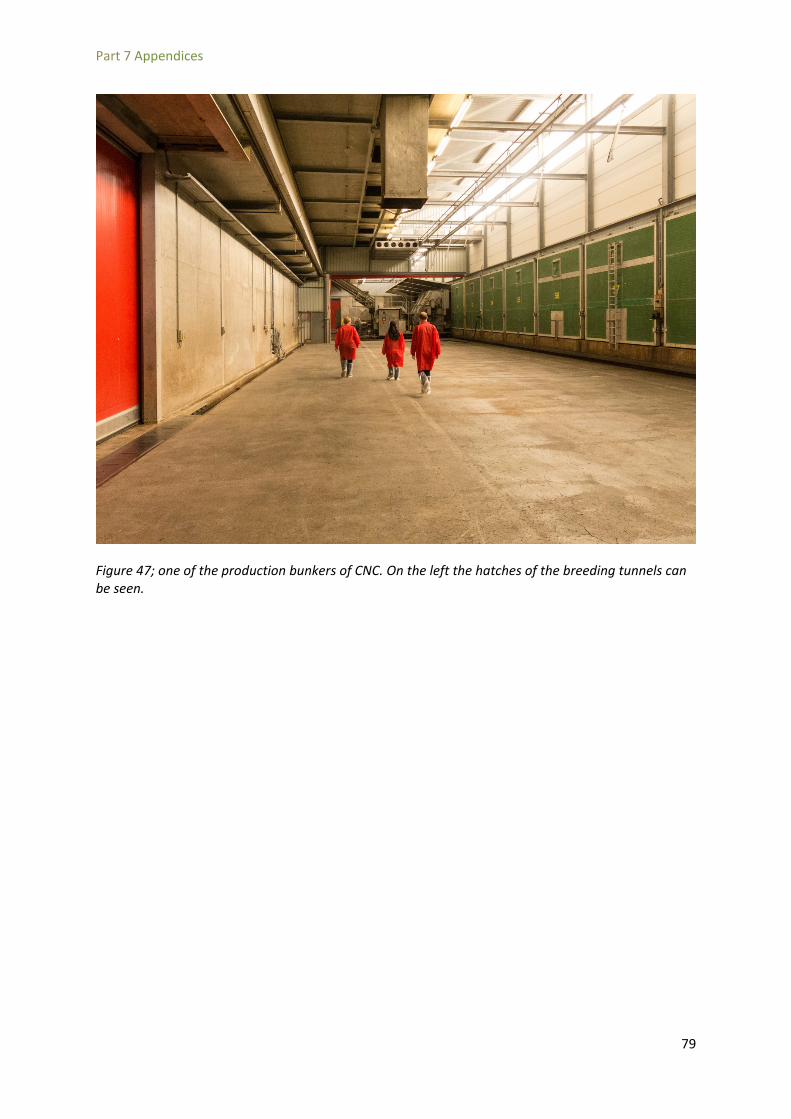
Part 7 Appendices
Figure 47; one of the production bunkers of CNC. On the left the hatches of the breeding tunnels can be seen.
79

Part 7 Appendices
Figure 48; breeding tunnel
80

Part 7 Appendices
Figure 49; spawn distribution machine
81

Part 7 Appendices
7.4 General protocol for creating mycelium-based material samples Creating Samples
1. Disinfect workspace and materials using a 95% alcohol solution. Wear gloves. If anything from outside of the disinfected area is brought in, disinfect it.
2. Weigh the dry substrate
3. Boil the substrate in water for 100 min
4. Weigh wet substrate
5. Extract moisture by hand
6. Weigh squeezed substrate
7. Place substrate and spawn in molds. Use a 10-20% spawn to total weight ratio for a growth period of 30 days. Ensure that the spawn is evenly spread through the mold.
8. Weigh the mold
9. Close the mold
10. Apply label to mold with content, mass and date of closing
11. Disinfect box with alcohol
12. Place the mold in a sterile controllable environment such as a larger closable box.
Growing conditions
13. Close the larger box and allow to grow for 30 days in a dark place at room temperature
14. It is advised to rotate the mold during growth to ensure a more homogeneous growth of the specimen.
Drying
15. After the growth period, weigh the sample. Then dry the sample at 150˚ for 120 minutes. Weigh at 20 min intervals
82