Embed Size (px)
Citation preview
HYDRAULIC DIVISION
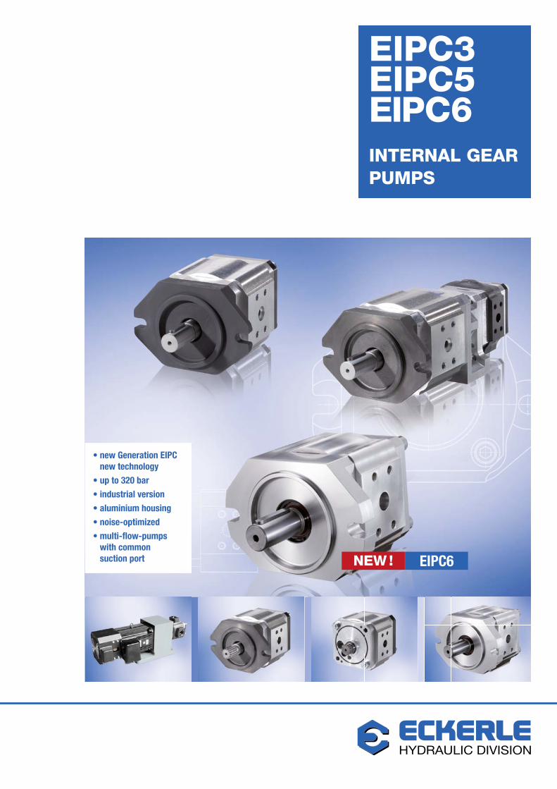
• new Generation EIPCnew technology
• up to 320 bar
• industrial version
• aluminium housing
• noise-optimized
• multi-flow-pumps with common suction port
EIPC3EIPC5EIPC6INTERNAL GEARPUMPS
EIPC6NEW !
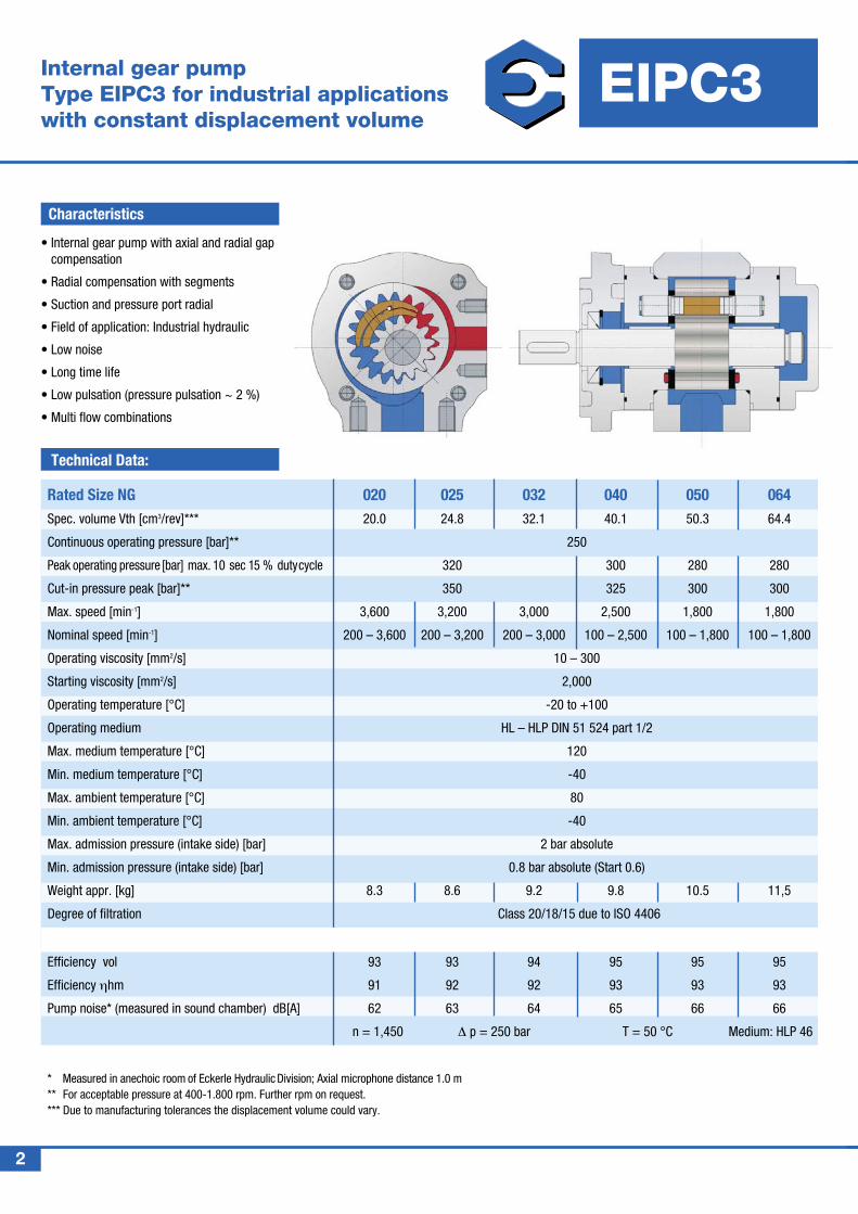
Internal gear pump Type EIPC3 for industrial applicationswith constant displacement volume
Characteristics
• Internal gear pump with axial and radial gap compensation
• Radial compensation with segments
• Suction and pressure port radial
• Field of application: Industrial hydraulic
• Low noise
• Long time life
• Low pulsation (pressure pulsation ~ 2 %)
• Multi flow combinations
2
EIPC3
HYDRAULIC DIVISION
Technical Data:
Rated Size NG 020 025 032 040 050 064Spec. volume Vth [cm3/rev]*** 20.0 24.8 32.1 40.1 50.3 64.4
Continuous operating pressure [bar]** 250
Peak operating pressure [bar] max. 10 sec 15 % duty cycle 320 300 280 280
Cut-in pressure peak [bar]** 350 325 300 300
Max. speed [min-1] 3,600 3,200 3,000 2,500 1,800 1,800
Nominal speed [min-1] 200 – 3,600 200 – 3,200 200 – 3,000 100 – 2,500 100 – 1,800 100 – 1,800
Operating viscosity [mm2/s] 10 – 300
Starting viscosity [mm2/s] 2,000
Operating temperature [°C] -20 to +100
Operating medium HL – HLP DIN 51 524 part 1/2
Max. medium temperature [°C] 120
Min. medium temperature [°C] -40
Max. ambient temperature [°C] 80
Min. ambient temperature [°C] -40
Max. admission pressure (intake side) [bar] 2 bar absolute
Min. admission pressure (intake side) [bar] 0.8 bar absolute (Start 0.6)
Weight appr. [kg] 8.3 8.6 9.2 9.8 10.5 11,5
Degree of filtration Class 20/18/15 due to ISO 4406
Efficiency vol 93 93 94 95 95 95
Efficiency ηhm 91 92 92 93 93 93
Pump noise* (measured in sound chamber) dB[A] 62 63 64 65 66 66
n = 1,450 ∆ p = 250 bar T = 50 °C Medium: HLP 46
* Measured in anechoic room of Eckerle Hydraulic Division; Axial microphone distance 1.0 m ** For acceptable pressure at 400-1.800 rpm. Further rpm on request. *** Due to manufacturing tolerances the displacement volume could vary.
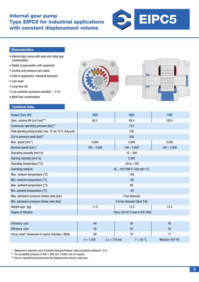
Internal gear pump Type EIPC5 for industrial applicationswith constant displacement volume
Characteristics
• Internal gear pump with axial and radial gap compensation
• Radial compensation with segments
• Suction and pressure port radial
• Field of application: Industrial hydraulic
• Low noise
• Long time life
• Low pulsation (pressure pulsation ~ 2 %)
• Multi flow combinations
EIPC5
HYDRAULIC DIVISION
Technical Data:
Rated Size NG 064 080 100Spec. volume Vth [cm3/rev]*** 65,3 80,4 100,5
Continuous operating pressure [bar]** 210
Peak operating pressure [bar] max. 10 sec 15 % duty cycle 230
Cut-in pressure peak [bar]** 250
Max. speed [min-1] 3,000 3,000 2,500
Nominal speed [min-1] 100 – 3,000 100 – 3,000 100 – 2,500
Operating viscosity [mm2/s] 10 – 300
Starting viscosity [mm2/s] 2,000
Operating temperature [°C] -20 to +100
Operating medium HL – HLP DIN 51 524 part 1/2
Max. medium temperature [°C] 120
Min. medium temperature [°C] -40
Max. ambient temperature [°C] 80
Min. ambient temperature [°C] -40
Max. admission pressure (intake side) [bar] 2 bar absolute
Min. admission pressure (intake side) [bar] 0.8 bar absolute (Start 0.6)
Weight appr. [kg] 11.5 13.0 13.5
Degree of filtration Class 20/18/15 due to ISO 4406
Efficiency ηvol 94 95 95
Efficiency ηhm 92 93 93
Pump noise* (measured in sound chamber) dB[A] 69 70 71
n = 1,450 ∆ p = 210 bar T = 50 °C Medium: HLP 46
* Measured in anechoic room of Eckerle Hydraulic Division; Axial microphone distance 1.0 m ** For acceptable pressure at 400-1.800 rpm. Further rpm on request. *** Due to manufacturing tolerances the displacement volume could vary.
3
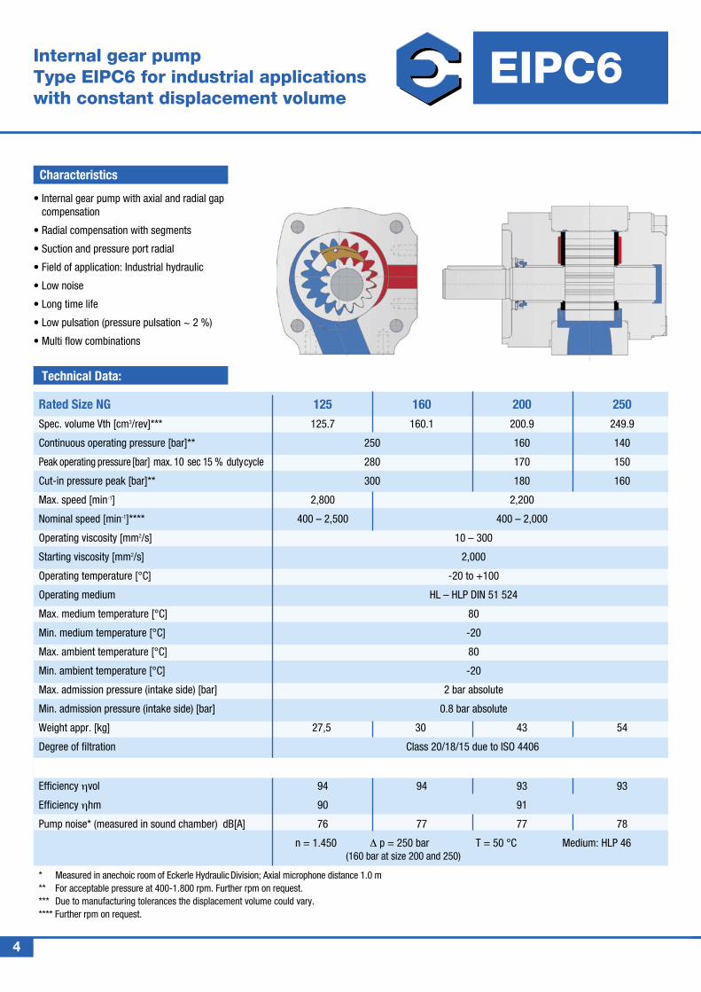
Internal gear pump Type EIPC6 for industrial applicationswith constant displacement volume
4
EIPC6
HYDRAULIC DIVISION
Characteristics
• Internal gear pump with axial and radial gap compensation
• Radial compensation with segments
• Suction and pressure port radial
• Field of application: Industrial hydraulic
• Low noise
• Long time life
• Low pulsation (pressure pulsation ~ 2 %)
• Multi flow combinations
Technical Data:
Rated Size NG 125 160 200 250Spec. volume Vth [cm3/rev]*** 125.7 160.1 200.9 249.9
Continuous operating pressure [bar]** 250 160 140
Peak operating pressure [bar] max. 10 sec 15 % duty cycle 280 170 150
Cut-in pressure peak [bar]** 300 180 160
Max. speed [min-1] 2,800 2,200
Nominal speed [min-1]**** 400 – 2,500 400 – 2,000
Operating viscosity [mm2/s] 10 – 300
Starting viscosity [mm2/s] 2,000
Operating temperature [°C] -20 to +100
Operating medium HL – HLP DIN 51 524
Max. medium temperature [°C] 80
Min. medium temperature [°C] -20
Max. ambient temperature [°C] 80
Min. ambient temperature [°C] -20
Max. admission pressure (intake side) [bar] 2 bar absolute
Min. admission pressure (intake side) [bar] 0.8 bar absolute
Weight appr. [kg] 27,5 30 43 54
Degree of filtration Class 20/18/15 due to ISO 4406
Efficiency ηvol 94 94 93 93
Efficiency ηhm 90 91
Pump noise* (measured in sound chamber) dB[A] 76 77 77 78
n = 1.450 ∆ p = 250 bar T = 50 °C Medium: HLP 46 (160 bar at size 200 and 250)
* Measured in anechoic room of Eckerle Hydraulic Division; Axial microphone distance 1.0 m ** For acceptable pressure at 400-1.800 rpm. Further rpm on request. *** Due to manufacturing tolerances the displacement volume could vary. **** Further rpm on request.
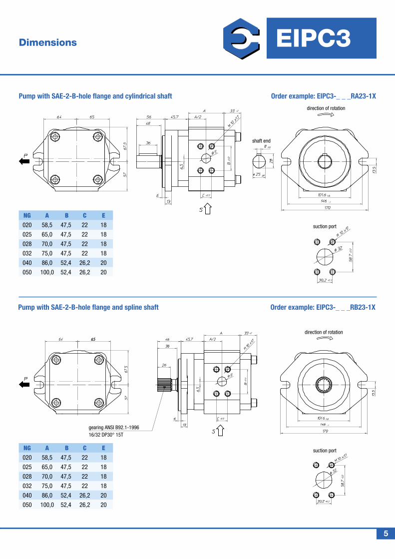
Pump with SAE-2-B-hole flange and spline shaft Order example: EIPC3-_ _ _RB23-1X
Dimensions EIPC3
HYDRAULIC DIVISION
Pump with SAE-2-B-hole flange and cylindrical shaft Order example: EIPC3-_ _ _RA23-1X
5
NG A B C E 020 58,5 47,5 22 18
025 65,0 47,5 22 18
028 70,0 47,5 22 18
032 75,0 47,5 22 18
040 86,0 52,4 26,2 20
050 100,0 52,4 26,2 20
NG A B C E 020 58,5 47,5 22 18
025 65,0 47,5 22 18
028 70,0 47,5 22 18
032 75,0 47,5 22 18
040 86,0 52,4 26,2 20
050 100,0 52,4 26,2 20
shaft end
suction port
direction of rotation
suction port
gearing ANSI B92.1-199616/32 DP30° 15T
direction of rotation
Dimensions
HYDRAULIC DIVISION
6
EIPC3
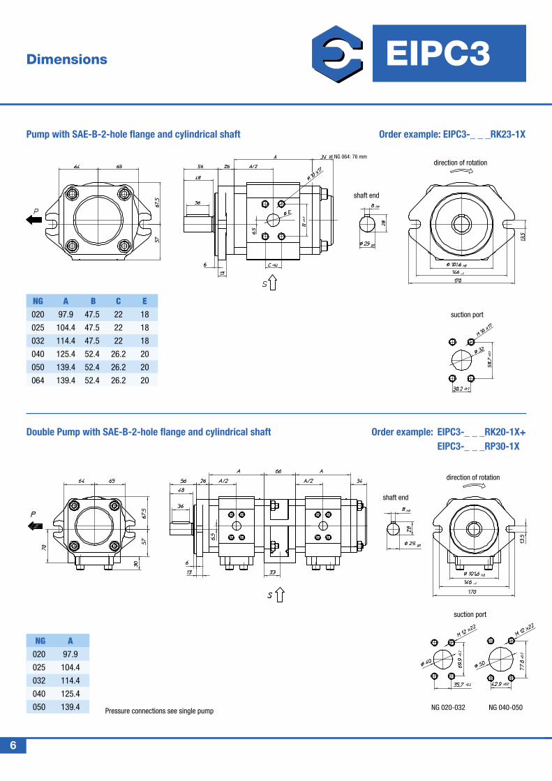
Pressure connections see single pump
Order example: EIPC3-_ _ _RK20-1X+ EIPC3-_ _ _RP30-1X
shaft end
suction port
NG A 020 97.9
025 104.4
032 114.4
040 125.4
050 139.4 NG 020-032 NG 040-050
Double Pump with SAE-B-2-hole flange and cylindrical shaft
Pump with SAE-B-2-hole flange and cylindrical shaft Order example: EIPC3-_ _ _RK23-1X
shaft end
suction port
NG A B C E 020 97.9 47.5 22 18
025 104.4 47.5 22 18
032 114.4 47.5 22 18
040 125.4 52.4 26.2 20
050 139.4 52.4 26.2 20
064 139.4 52.4 26.2 20
at NG 064: 76 mmdirection of rotation
direction of rotation
Dimensions
HYDRAULIC DIVISION
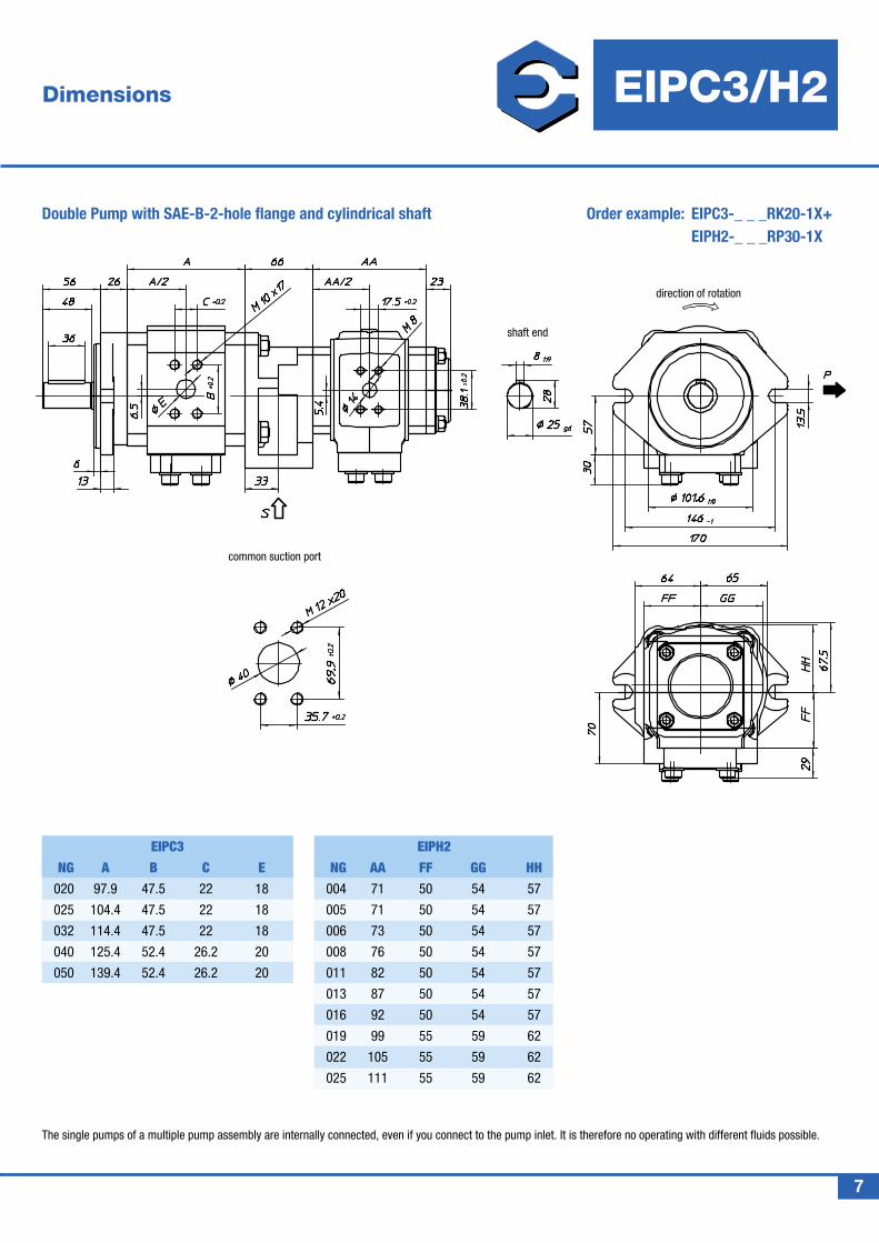
Order example: EIPC3-_ _ _RK20-1X+ EIPH2-_ _ _RP30-1X
shaft end
NG A B C E 020 97.9 47.5 22 18
025 104.4 47.5 22 18
032 114.4 47.5 22 18
040 125.4 52.4 26.2 20
050 139.4 52.4 26.2 20
NG AA FF GG HH 004 71 50 54 57
005 71 50 54 57
006 73 50 54 57
008 76 50 54 57
011 82 50 54 57
013 87 50 54 57
016 92 50 54 57
019 99 55 59 62
022 105 55 59 62
025 111 55 59 62
EIPC3 EIPH2
Double Pump with SAE-B-2-hole flange and cylindrical shaft
common suction port
7
EIPC3/H2
direction of rotation
The single pumps of a multiple pump assembly are internally connected, even if you connect to the pump inlet. It is therefore no operating with different fluids possible.
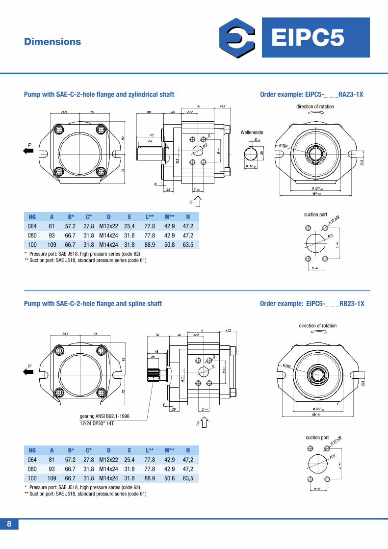
Wellenende
suction port
direction of rotation
Dimensions EIPC5
HYDRAULIC DIVISION
Pump with SAE-C-2-hole flange and zylindrical shaft Order example: EIPC5-_ _ _RA23-1X
Order example: EIPC5-_ _ _RB23-1X
Pump with SAE-C-2-hole flange and spline shaft
* Pressure port: SAE J518, high pressure series (code 62) ** Suction port: SAE J518, standard pressure series (code 61)
* Pressure port: SAE J518, high pressure series (code 62) ** Suction port: SAE J518, standard pressure series (code 61)
8
NG A B* C* D E L** M** N 064 81 57.2 27.8 M12x22 25,4 77.8 42.9 47.2
080 93 66.7 31.8 M14x24 31.8 77.8 42.9 47.2
100 109 66.7 31.8 M14x24 31.8 88.9 50.8 63.5
NG A B* C* D E L** M** N 064 81 57.2 27.8 M12x22 25.4 77.8 42.9 47,2
080 93 66.7 31.8 M14x24 31.8 77.8 42.9 47,2
100 109 66.7 31.8 M14x24 31.8 88.9 50.8 63,5
gearing ANSI B92.1-199612/24 DP30° 14T
direction of rotation
suction port
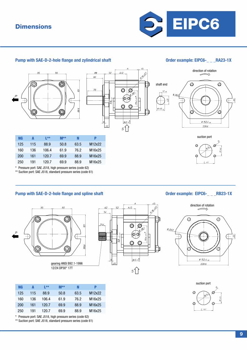
Dimensions EIPC6
HYDRAULIC DIVISION
Pump with SAE-D-2-hole flange and zylindrical shaft Order example: EIPC6-_ _ _RA23-1X
Order example: EIPC6-_ _ _RB23-1X
Pump with SAE-D-2-hole flange and spline shaft
9
NG A L** M** N P 125 115 88.9 50.8 63.5 M12x22
160 136 106.4 61.9 76.2 M16x25
200 161 120.7 69.9 88.9 M16x25
250 191 120.7 69.9 88.9 M16x25
NG A L** M** N P 125 115 88.9 50.8 63.5 M12x22
160 136 106.4 61.9 76.2 M16x25
200 161 120.7 69.9 88.9 M16x25
250 191 120.7 69.9 88.9 M16x25
* Pressure port: SAE J518, high pressure series (code 62) ** Suction port: SAE J518, standard pressure series (code 61)
* Pressure port: SAE J518, high pressure series (code 62) ** Suction port: SAE J518, standard pressure series (code 61)
gearing ANSI B92.1-199612/24 DP30° 17T
direction of rotation
suction port
shaft end
direction of rotation
suction port
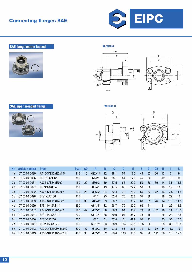
Connecting flanges SAE EIPC
HYDRAULIC DIVISION
SAE pipe threaded flange
SAE flange metric tapped Version a
Version b
Nr. Article number Type Pmax AD A B C D E F G1 G2 H I L
1a 07 07 04 0030 AD15-SAE12M22x1,5 315 15 M22x1.5 12 38.1 54 17.5 46 52 60 13 7 9
1b 07 07 04 0026 EFG1/2-SAE12 350 G1/2“ 13 38.1 54 17.5 46 36 19 19 9
2a 07 07 04 0031 AD22-SAE34M30x2 160 22 M30x2 19 47.5 65 22.2 50 60 69 14 7.5 11.5
2b 07 07 04 0027 EFG3/4-SAE34 350 G3/4“ 19 47.5 65 22.2 50 36 18 19 11
3a 07 07 04 0032 AD28-SAE100M36x2 160 28 M36x2 24 52.4 70 26.2 55 63 72 16 7.5 11.5
3b 07 07 04 0028 EFG1-SAE100 315 G1“ 25 52.4 70 26.2 55 38 18 22 11
4a 07 07 04 0033 AD35-SAE114M45x2 160 35 M45x2 29 58.7 79 30.2 68 65 76 14 10.5 11.5
4b 07 07 04 0029 EFG1 1/4-SAE114 250 G1 1/4“ 32 58.7 79 30.2 68 41 21 22 11.5
5a 07 07 04 0037 AD42-SAE112M52x2 160 42 M52x2 36 69.9 94 35.7 78 70 82 16 11 13.5
5b 07 07 04 0034 EFG1 1/2-SAE112 200 G1 1/2“ 38 69.9 94 35.7 78 45 25 24 13.5
6b 07 07 04 0036 EFG2-SAE200 200 G2“ 51 77.8 102 42.9 90 45 25 30 13.5
7b 07 07 04 0041 EFG2 1/2-SAE212 160 G2 1/2“ 63 88.9 114 50.8 105 50 25 30 13.5
8a 07 07 04 0042 AD30-SAE100M42x2HD 400 30 M42x2 25 57.2 81 27.8 70 82 95 24 13.5 13
9a 07 07 04 0043 AD38-SAE114M52x2HD 400 38 M52x2 32 79.4 113 36.5 95 96 111 30 16 17.5
10
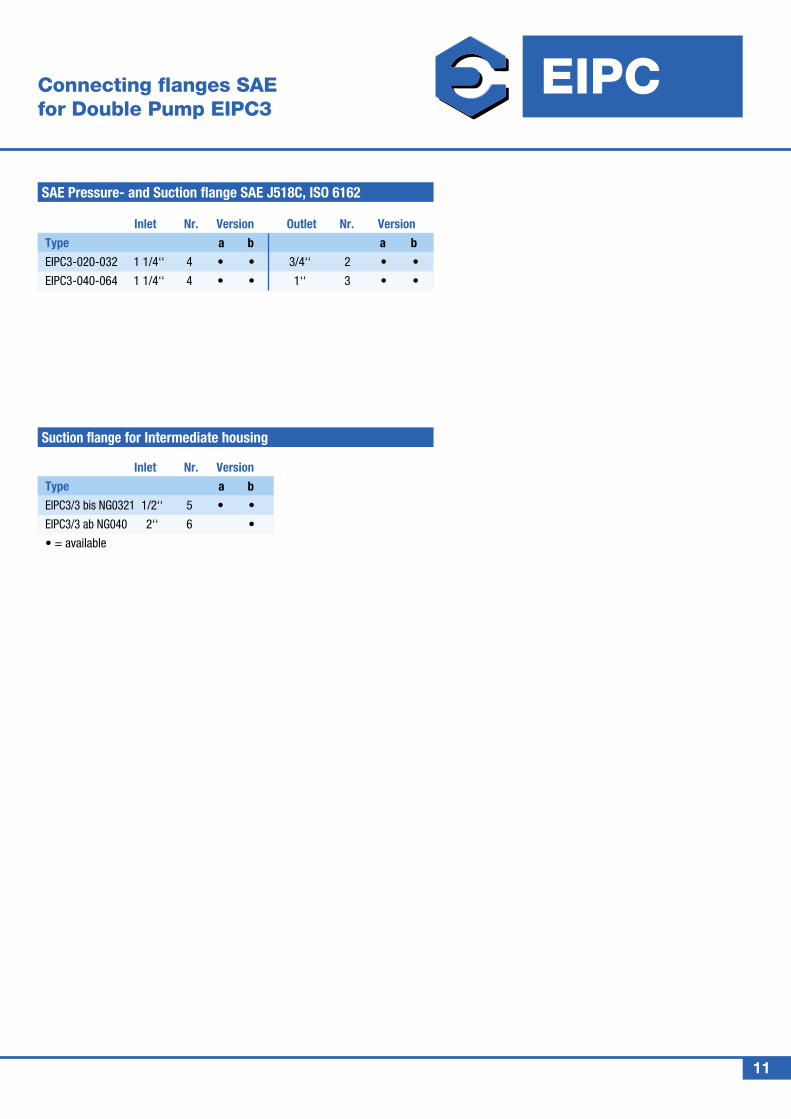
Connecting flanges SAE for Double Pump EIPC3
EIPC
HYDRAULIC DIVISION
SAE Pressure- and Suction flange SAE J518C, ISO 6162
Suction flange for Intermediate housing
Inlet Nr. Version
Type a b
EIPC3/3 bis NG0321 1/2‘‘ 5 • •
EIPC3/3 ab NG040 2‘‘ 6 •
• = available
Inlet Nr. Version Outlet Nr. Version
Type a b a b
EIPC3-020-032 1 1/4‘‘ 4 • • 3/4‘‘ 2 • •
EIPC3-040-064 1 1/4‘‘ 4 • • 1‘‘ 3 • •
11
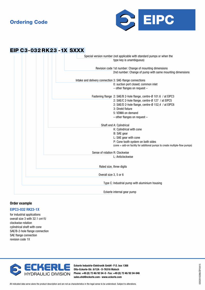
Order example
EIPC3-032 RK23-1Xfor industrial applications overall size 3 with 32.1 cm3/U clockwise rotation cylindrical shaft with cone SAE/B-2-hole flange connection SAE flange connection revision code 1X
Ordering Code
EIP C3-032RK23 -1X SXXXSpecial version number (not applicable with standard pumps or when the
type key is unambiguous)
Revision code 1st number: Change of mounting dimensions 2nd number: Change of pump with same mounting dimensions
Fastening flange 2: SAE/B 2-hole flange, centre-Ø 101.6 / at EIPC3 2: SAE/C 2-hole flange, centre-Ø 127 / at EIPC5 2: SAE/D 2-hole flange, centre-Ø 152,4 / at EIPC6 3: Direkt fixture
5: VDMA on demand – other flanges on request –
Sense of rotation R: Clockwise L: Anticlockwise
Overall size 3, 5 or 6
Shaft end A: Cylindrical K: Cylindrical with cone B: SAE gear L: SAE gear with cone P: Cone tooth system on both sides
Rated size, three digits
Type C: Industrial pump with aluminium housing
Eckerle internal gear pump
(cone = add-on facility for additional pumps to create multiple-flow pumps)
Intake and delivery connection 3: SAE-flange connections 0: suction port closed; common inlet – other flanges on request –
EIPC
HYDRAULIC DIVISION
HYDRAULIC DIVISION
All indicated data serve alone the product description and are not as characteristics in the legal sense to be understood. Subject to alterations. 0202
0102
66/Ü
P/04
15Eckerle Industrie-Elektronik GmbH · P.O. box 1368Otto-Eckerle-Str. 6/12A · D-76316 MalschPhone: +49 (0) 72 46/92 04-0 · Fax: +49 (0) 72 46/92 [email protected] · www.eckerle.com


