Embed Size (px)
Citation preview

In Proceedings of the 22nd International Conference on Conceptual Modeling, Chicago, IL, November 2003.
EITH – A Unifying Representation for Database Schema and Application Code in Enterprise Knowledge
Extraction
Mark S. Schmalz, Joachim Hammer, MingXi Wu, and Oguzhan Topsakal
Department of CISE, University of Florida
Gainesville, FL 32611-6120, USA {mssz,jhammer,mingxi,topsaka}@cise.ufl.edu
Abstract. The integration of heterogeneous legacy databases requires understanding of database structure and content. We previously developed a theoretical and software infrastructure to support the extraction of schema and business rule information from legacy sources, combining database reverse engineering with semantic analysis of associated application code (DRE/SA). In this paper, we present a compact formalism called EITH that unifies the representation of database schema and application code. EITH can be efficiently derived from various types of schema representations, particularly the relational model, and supports comparison of a wide variety of schema and code constructs to enable interoperation. Unlike UML or E/R diagrams, for example, EITH has compact notation, is unambiguous, and uses a small set of efficient heuristics. We show how EITH is employed in the context of SEEK, using a construction project management example. We also show how EITH can represent various structures in relational databases, and can serve as an efficient representation for E/R diagrams. This suggests that EITH can support efficient matching of more complex, hierarchical structures via indexed tree representations, without compromising the EITH design philosophy or formalism.
1 Introduction Inherent in numerous techniques for integrating heterogeneous legacy data sources is the concept of logical integration of data [15] in terms of a unifying model that supports analysis and decision making procedures convenient to the user. Logical integration requires transformation of legacy source structure and content to meet or match the structure and content requirements of an analysis model (AM), as well as translation of user queries or data updates mediated through the AM. Common to this integration process is the development of wrappers that perform data and query transformation between a legacy source and the AM. This paper presents an efficient formalism that supports the logical integration of heterogeneous databases, in particular, efficient wrapper design and production. Our previous work in this area provided formalisms for wrapper description and semi-automatic wrapper generation, with understanding of database structure, content, and associated data manipulation rules [7, 9, 14]. Here, we extend this work to provide a formalism called EITH that supports schema comparison and transformation, thereby facilitating more accurate and

efficient automated wrapper generation. EITH serves as an efficient representation for E/R diagrams – we show how EITH can be used to represent diverse constructs in relational databases described by E/R diagrams. We also suggest that EITH can be employed in the generation and recursive updating of ontological formalisms to support enterprise domain extension and eventual cross-domain semantic understanding.
Current implementations of database interoperability and integration rely on technologies developed as part of the TSIMMIS [2] or Garlic [4] projects, for example, which primarily emphasize distributed query processing and data transformation. In contrast, our SEEK and EITH approaches support deeper semantic understanding of legacy data, which is synergistic with the following objectives:
1. Unified EITH representation of database structure in terms of schema, business rules in application code, and relationships between these entities;
2. Understanding of functional relationships between data objects in the context of an application domain, which is simplified by the EITH formalism;
3. Comparison between data objects ranging from the schema-entity or code-operand level up to relations or schema (data model) as well as business rules or body of code (rule model), again simplified by EITH; and
4. Eventual automatic or semi-automatic construction or augmentation of domain-descriptive ontologies from extracted legacy schema and code represented in terms of EITH.
Our approach differs from previous structural-based wrapper generation techniques in using schema, business rules, and semantic relationships between these entities to drive design and implementation of the underlying EITH representation. This approach, combined with proven theory and software development practice, produces a representation that is efficient spatially and computationally, tractably unifies both data and code, and supports semantic operations such as schema comparison, schema and code understanding, as well as eventual ontology building and merging.
The remainder of this paper is organized as follows. Sect. 2 reviews previous work in data reverse engineering and wrapper generation that motivates our current research. We show how EITH evolved from this work, and how it supports representation of schema and code at multiple levels of abstraction. Sect. 3 presents EITH theory, which is shown to represent numerous schema structures. Sect. 4 exemplifies application of EITH to (a) represent different schemas or application code in disparate legacy sources and (b) show how this representation facilitates source comparison with respect to a prespecified analysis model also represented in terms of EITH. Sect. 5 discusses future uses of EITH in semantic understanding and cross-domain database interoperability. Conclusions and suggestions for future work are presented in Sect. 6.
2 Extraction and Representation of Database Knowledge
2.1 Review of our Previous Work in Enterprise Knowledge Extraction
This section presents a brief overview of our research in enterprise knowledge extraction and integration, further elaborated in [10]. A high-level view of the SEEK architecture (Fig. 1), which follows established mediation/wrapper methodologies

(e.g., TSIMMIS [2], Garlic [4]) and provides a middleware layer that connects legacy information sources and decision makers/decision support applications. The Hub provides decision support for an extended enterprise of firms (e.g., a construction supply chain). Decision support information is gathered from firms via SEEK connection tools. The Analysis Module (AM) performs knowledge composition or mediation [16] on legacy data extracted from the Firm. The AM does not cache data, but connects in real time with source wrappers, which translate between data representations and query formalisms of the Hub/AM and underlying source(s).
HUB
Wrapper
AnalysisModule
KnowledgeExtraction
Module
SEEK componentsDomain Expert
Wrapper
Legend: run-time/operational data flow build-time/set-up/tuning data flow
FirmConnection ToolsHub
Legacy dataand systems
Fig. 1. Schematic diagram of the conceptual architecture of the SEEK system and related components
In practice, multiple Hubs can have diverse internal data formats and languages. However, SEEK is limited to specific forms of data extraction constrained by decision support capabilities provided by each class of Hubs. Thus, Hub-AM wrappers are simple to implement and can support multiple Hubs, increasing SEEK’s scalability.
Firm SEEK Components
Hub Analysis SEEK Legacy Module Wrapper Source
QH
RH
QA
DA
QL
DL
(result)
fQ fD
QA
RA
W
Fig. 2. Overview of the interactions between Hub, SEEK components and Firm
At runtime, (i.e., after the SEEK wrapper W and analysis module AM are configured), the AM accepts a query issued by the Hub (QH in Fig. 2) that has been converted into a query (QA) which the AM can understand using W. The AM processes a Hub request and issues one or more queries (QA) to W to obtain legacy data needed to satisfy the Hub’s request. The SEEK wrapper produces one or more queries (QL) in a format that the legacy source can understand. The legacy source processes QL and returns legacy data (DL) that is transformed by the SEEK wrapper into data (DA) that is tractable to
the AM. The AM processes this data and returns a result (RH) via the wrapper W to the Hub that fulfills the original Hub query (QH).
As SEEK tools must be instantiated for each firm, it is important to provide rapid configuration with minimal human support. Instantiation is accomplished semi-automatically during build-time by SEEK’s knowledge extraction module (KEM) that directs wrapper configuration. A SEEK-specific representation of operational knowledge in the sources is obtained via domain specific templates that describe semantics of commonly-used structures and schemas. KEM queries a legacy source using the initial instantiation of a simple (generic) SEEK wrapper. Via data reverse engineering (DRE), KEM constructs a legacy schema representation that includes legacy data semantics determined, for example, from queries, data samples, application code, and user input (as required). Using an iterative, step-wise refinement process, KEM constructs mappings fQ and f D that extend the initial SEEK wrapper to perform the aforementioned query and data translations (per Fig. 2). A wrapper generation toolkit [6] implements the customized wrappers. Human domain experts can assist this process following initial configuration, compensating for poor legacy documentation while expanding scope and quality of the SEEK knowledge representation.
2.2 The EITH Representation and its Relationship to SEEK
To support SEEK’s unified representation of diverse data sources, the EITH representation of a database has the following levels of abstraction: • High-Level Semantics describe the types of entities within a schema and their
high-level meanings in a context that is a superset of the domain semantics. For example, in the SEEK project management model, we have defined physical objects, abstract objects, and constraints. The former include people and materials, while abstractions include objects such as Project and Task.
• Constraint Layer describes constraints on entities and relationships between constraints. For example, in a SEEK project management model, a Schedule is a high-level constraint, while its constituents (e.g., abstractions such as Time Interval and Cost) are low-level constraints. Other constraints include variables such as Flag and Type.
• Schema Layer describes database structure in terms of a schema with data instances. This is determined primarily by SEEK’s KEM.
• Formulaic Layer contains mathematical relationships between data objects, which are typically found in application code. For example, total project cost is the sum of the individual task costs, since a project is comprised of its tasks. The high-level semantics and constraints comprise instances of an ontological
framework for a superset of the legacy data. For example, a project management model could be associated with an ontology that would include but not be limited to Entities, Relationships between Entities, Constraints on Entities, and Constraints on Relationships. Additional information in the ontology would include business rules and generic information that would be specialized in the Formulaic Layer. The challenges in representing such information include (a) compact but sufficiently expressive formalisms lacking ambiguities that confound interpretation of knowledge represented in terms of the formalism; (b) unification of data and code representations using one set of representational building

blocks, for efficiency; and (c) representation of ontological layers and knowledge partitions within layers via well-established data structures whose processing is well understood, and which are represented by a rigorous, concise, and unified formalism.
We next overview EITH, and discuss its Schema Layer representation in terms of the EITH formalism, then illustrate EITH’s unifying capabilities in terms of code representation in the Formulaic Layer (Fig. 4). For readers unfamiliar with schema representation, theory and more complex representation issues are discussed in Sect. 3, while EITH’s relationship to High-Level Semantics and Constraint Layers is clarified in Sect. 5.
Object Entity Relation Relationship Relation Compound Relation Graphical Representation Relation Code R0 R1 R2 R3 Alphabetic Code E I T H
Fig. 3. High-level graphical representation of building blocks for description of database structure: entity, relation, relationship relation, and compound relation
The structures shown in Fig. 3 can represent typical structures in a database schema, for example, entities, relations, relationship relations, and compound relations. To support efficient comparison of structures within or between schemas, compact names were devised for EITH constructs (shown at the bottom of Fig. 3).
The problem of representing programs has been studied extensively in the context of software engineering [1]. For example, in traditional interprocedural analysis, a program is abstracted by a call graph [5]. Compilers use a variety of intermediate representations of programs, such as abstract syntax trees (AST), control flow graphs, def-use chains, etc. For more complex manipulations of programs, the program dependence graph (PDG) [3] and the dependence flow graph (DPG) [12] have been used. Finally, in program pattern matching [11], interesting programming patterns are stored in templates using a so-called ‘pattern language’. These templates are then compared to patterns in the source code. The majority of published representations were developed in the context of program compilation and program manipulation problems such as slicing but are not adequate for representing the deep semantics of both code constructs as well as their relationships to database entities in a compact yet unambiguous and easy-to-use format.
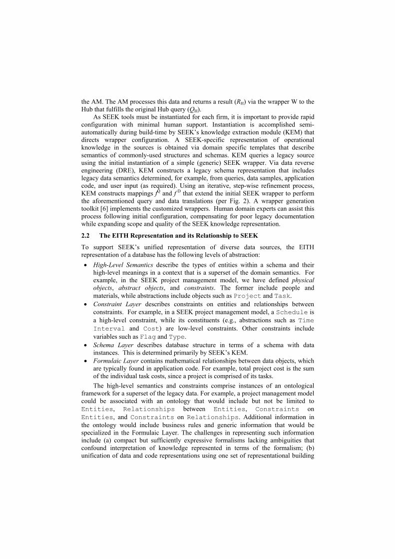
2.2.1 Example: Schema Representation. Consider the construction project schema shown in Fig. 4a, and its graphical EITH representation shown in Fig. 4b. The high-level alphabetic EITH representation is given by S = {I,I,I,I,I}, which denotes an unordered set of relations. Note that the mapping which produces S is irreversible, in the sense that the schema cannot be completely reconstructed from S because the entity and relation names, and cardinality of the relations, are missing. However, we are implementing a frame-based elaboration of EITH, whereby each entity and relation can be described in terms of its attributes, similar to UML [13]. This approach is

advantageous because design and implementational details are retained but migrated to the next-lower level of the graphical representation, thereby facilitating comprehension and ease of maintenance.
has
Project
Task
1
N
uses
Material
1
N
uses
Resource
M
N
has
Schedule
M
N
has
Availability
1
N
(a)
Project
has uses
Task
Resource
1
N
M
N
Task
uses
Task
Material
1
N
has
Resource
Schedule
M
N
has
Resource
Availability
1
N
(b)
Fig. 4. Construction project schema (a) E/R diagram and (b) graphical EITH representation
EITH can be extended to represent database application code by observing that a leaf (internal node) in a hierarchical relationship such as an abstract syntax tree or AST can correspond to an entity (resp. relationship) in Fig. 3. We thus discovered EITH representations for code constructs such as unary operations of assignment, binary operations with assignment, control structures such as if-then-else and loops, as well as sequences or concurrently executable collections of operations. A key advantage of this approach is that ASTs can represent both schema and code, which supports efficient translation of source representations into XML format.

Object Operand Unary Op Binary Operation Conditional Assignment Graphical Representation Dataflow Control Flow
Fig. 5. Graphical representation of building blocks for description of constructs in code: operand, unary operation, binary operation with assignment to a result, and a conditional assignment. Data and control flow links elaborate the schema objects of Fig. 3
Slight modifications to the EITH schema objects portrayed in Fig. 3 produce the code objects shown in Fig. 5, which include the following:
• Operands in code (EITH symbol: O) are conceptually similar to database Entities, although represented by a square instead of a rectangle;
• Operations in code (U, B, or C for unary, binary, or conditional operations), similar to schema Relations, are represented graphically by a circle or oval, versus a diamond for a database relation;
• Data transfer link (-) indicates dataflow from left to right. • Causal link (dashed arrow in graphics, > in text) illustrates control flow within
a structure such as a loop (L), multiple if statement, or case statement (aggregation of C-type primitives); and
Multi-operator groups of operations executed sequentially (denoted by [ ] or S), versus unordered collections ({ }), thus representing control dependency.
For-Loop Binary Operation Sequence of Operations
for i = 1 to n do: a = a + i;
n
1
= i for + a
a
i
=
x = 4; y = w; z = x * y;
4
x
= x z
x
y
=
w
y
=
(a) (b)
Fig. 6. Example of graphical EITH representation for application code: (a) loop and (b) multi-operator sequence. Note the transfer of control in the loop indicated by the dashed arc
2.2.2 Example Application Code Representation. Consider the loop in Fig. 6a, where the for operator transfers control to the addition operation. Control transfers to the for operator when the addition operation completes, then back to the addition operation following index incrementation, until the condition i > n signals loop exit. The sequence of operations itself does not transfer control from the statement x = 4 to

the statement y = w, since no dependencies exist between these statements. Although one could construct a control arc from either of these statements to z = x + y, this would be superfluous and misleading, since these statements and z = x + y have no control dependencies. Instead, data dependencies exist among the three statements depicted in Fig. 6b, which can be detected during the code slicing performed as part of the DRE/SA operation in SEEK’s KEM. Also, because EITH is modular, a sequence of operations such as shown in Fig. 6b can be substituted for the addition operation comprising the loop body in Fig. 6a. 2.2.3 Implementation Issues in SEEK. Note that the graphical constructs in Figs. 4 and 6 resemble ASTs, albeit with some lack of reduction. ASTs provide a convenient representation for low-level EITH primitives (e.g., I,T,H,U,B, or C) and higher-level data structures such as acyclic directed graphs. Techniques for derivation of an AST from a well-specified formal language are well documented in the literature of programming languages. Algorithms for manipulating or comparing ASTs are well represented in the literature.
The graphical EITH representation and AST representation are isomorphic: inspection of Fig. 7 discloses that an AST is obtained by renaming the entities (operands) and relations (operators) of the database-specific (resp. code-specific) primitives shown in Figs. 3 and 4. Salient examples are presented in Fig. 7. In practice, we obtain code primitives as subtrees of an AST by parsing application code (e.g., in the DRE/SA phase of SEEK knowledge extraction). Similarly, the database primitives shown in Fig. 3 can be thought of as subtrees of an E/R diagram obtained from applying SEEK’s DRE process to a database schema.
1 2 3 4 5 6 A B C D E F
A
B
C
D F
E 1
2
3
4 6
5
Database Representation Code Representation
Fig. 7. Examples of correspondence between representational primitives and abstract syntax tree representation, where database relations are graphically distinguished from code operations (which mathematically are relations) by the boldness of the internal node border.
By viewing the E/R diagram (parse tree) as a graphical representation of a schema (resp. code fragment), and by representing these concisely with the EITH alphabet Σ = {B, C, E, H, I, L, O, S, T, U, >, [ ], { }}, we can structurally compare objects within and between databases. Due to isomorphism between data and code primitives (e.g., between E and O, I and U, T and B, H and C) EITH provides a unifying description of database and application code structure. This has the practical advantage that the same
manipulation and comparison algorithms can be applied to schema or code representations in SEEK, thus reducing software duplication and maintenance overhead. Since SEEK focuses on schema and code objects that are typically small, these comparison algorithms can be small and efficient. As discussed in Sec. 3, EITH can be used to represent complex structures, for which similar claims hold. We next discuss the theoretical basis, notation, and coverage of the EITH representation.
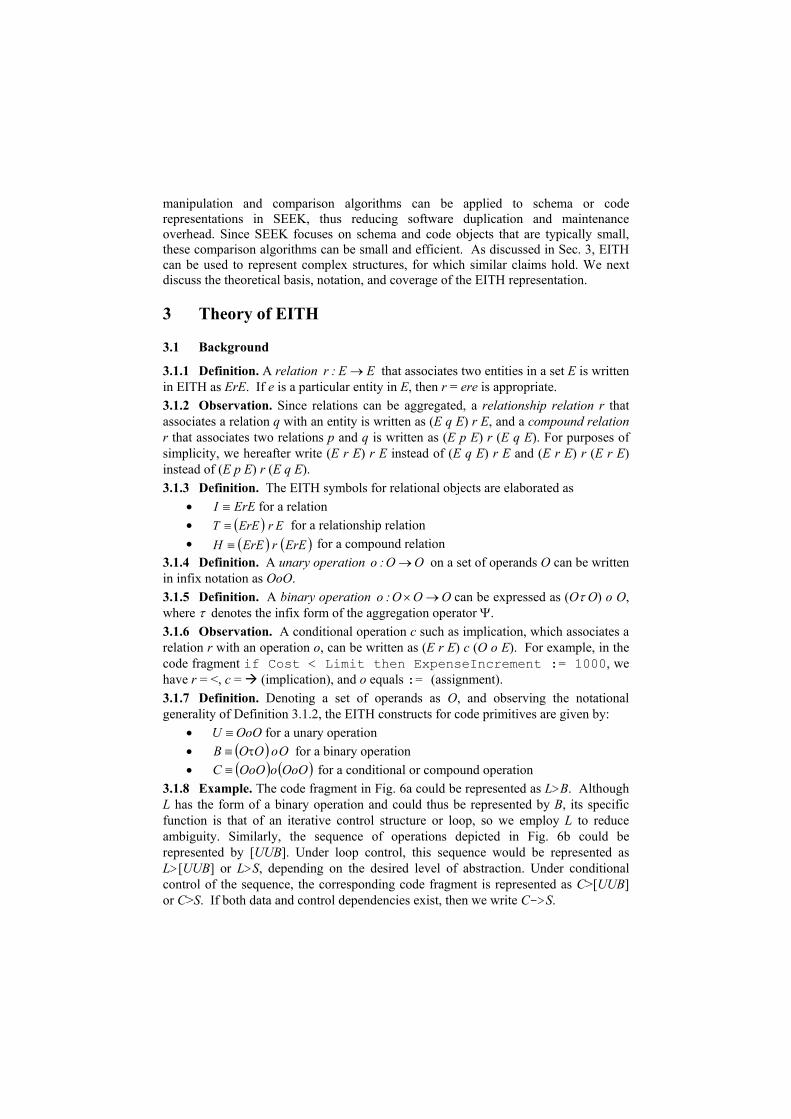
3 Theory of EITH
3.1 Background
3.1.1 Definition. A relation that associates two entities in a set E is written in EITH as ErE. If e is a particular entity in E, then r = ere is appropriate.
EE:r →
3.1.2 Observation. Since relations can be aggregated, a relationship relation r that associates a relation q with an entity is written as (E q E) r E, and a compound relation r that associates two relations p and q is written as (E p E) r (E q E). For purposes of simplicity, we hereafter write (E r E) r E instead of (E q E) r E and (E r E) r (E r E) instead of (E p E) r (E q E). 3.1.3 Definition. The EITH symbols for relational objects are elaborated as
• ErEI ≡ for a relation • ( ) ErErET ≡ for a relationship relation • ( ) ( )ErErErEH ≡ for a compound relation
3.1.4 Definition. A unary operation o on a set of operands O can be written in infix notation as OoO.
OO: →
3.1.5 Definition. A binary operation OOO:o →× can be expressed as (Oτ O) o O, where τ denotes the infix form of the aggregation operator Ψ. 3.1.6 Observation. A conditional operation c such as implication, which associates a relation r with an operation o, can be written as (E r E) c (O o E). For example, in the code fragment if Cost < Limit then ExpenseIncrement := 1000, we have r = <, c = (implication), and o equals := (assignment). 3.1.7 Definition. Denoting a set of operands as O, and observing the notational generality of Definition 3.1.2, the EITH constructs for code primitives are given by:
• for a unary operation OoOU ≡• ( ) OoOOB τ≡ for a binary operation
( ) (• )OoOoOoOC ≡ for a conditional or compound operation 3.1.8 Example. The code fragment in Fig. 6a could be represented as L>B. Although L has the form of a binary operation and could thus be represented by B, its specific function is that of an iterative control structure or loop, so we employ L to reduce ambiguity. Similarly, the sequence of operations depicted in Fig. 6b could be represented by [UUB]. Under loop control, this sequence would be represented as L>[UUB] or L>S, depending on the desired level of abstraction. Under conditional control of the sequence, the corresponding code fragment is represented as C>[UUB] or C>S. If both data and control dependencies exist, then we write C->S.

3.1.9 Observation. It can be claimed that the T and H constructs in Fig. 3, while useful as high-level abstractions, inaccurately portray the implementation of relationship relations and compound relations in actual schema. This problem is solved by the use of a construct called a super-relation.
e1
e2
r1
e3
r2
e4
e5
r4
e6
r5
e1
e2
r1
e3
r2
r3 e4 r3
Super-Relationsdenoted by R’
(a) (b)
Fig. 8. EITH representation of low-level schema structure using super-relation R’ to represent (a) T-type relation as T’ = (e1 R’e3) r3 e4, and (b) H-type relation as H’ = (e1 R’e3) r3 (e4 R’e6).
3.1.10 Definition. An EITH super-relation, denoted by (’) following the relation designator (e.g., T’), is an aggregate relationship that associates two relations with an entity, such that R’ is of form rEr. As exemplified in Fig. 8a, R’ is defined in terms of an entity (e2), where e1r1e2, e2r2e3, and e2r3e4 exist. Then, R’ = (r1e2r2) if and only if the aggregation of e1R’e3 and e4r3R’ comprises a relationship relation. 3.1.11 Example. In Fig. 8a, the super-relation R’ = r1e2r2 supports expression of the T-type construct implementationally as T’ = (e1 R’e3) r3 e4. Similarly, in Fig. 8b, the use of R’ in both the left and right I-type sub-constructs of H = I r I allows us to express the H-type construct implementationally as H’ = (e1 R’e3) r3 (e4 R’e6). 3.1.12 Observation. The super-relation thus enables representation of EITH constructs at the Schema and Formulaic Levels of our ontology, and maintains rigor with respect to database implementation practice. In practice, T’ in Figure 8a would be constructed by a postprocessor, which is designed to (1) input the results of SEEK DRE/SA, (2) find the common entity (e.g., e2), (3) determine if e1r1e2, e2r2e3, and e2r3e4 exist in the schema, (4) aggregate (r1e2r2) to form R’, then (5) verify that the aggregation (e1R’e3, e4r3R’) comprises a relationship relation. The latter step can be performed with heuristics from our DRE/SA module. The postprocessor is currently being implemented as part of SEEK’s KEM. 3.1.13 Remark. The rules shown in Definition 3.1.3 also apply to I’, T’, and H’ representations of I, T, and H constructs, per Example 3.1.11. We next show that super-relations enable EITH to represent a wide variety of schema structures.
3.2 Coverage of EITH in Realistic Database Applications
In order to represent schema structures as complex and diverse as snowflakes, stars, or rings, we use a super-relation to reduce these configurations to a hierarchical collection of I, T, and H relations. For example, as shown in Fig. 9a, a four-petaled snowflake S4

that has a central super-relation R’ can be expressed as S4 ≡ E r (E R’ E) r E. From Definition 3.1.3 and Remark 3.1.13, we have I ≡ E R’ E. Thus, we can express the four-petaled snowflake as S4 ≡ E r I’ r E ≡ E r T’.
e R’ e
e r e r
λ Null Relation
(a)
(b)
(c)
Super-Relation R’
Fig. 9. Representation of more complex schema structures by EITH: (a) four-petaled snowflake, (b) ring, and (c) ternary relation
Note that these different expressions are equivalent, and thus do not introduce ambiguity into the EITH representation, since E r T’ can be expanded as E r (I’ r E), which can, in turn be expanded to yield E r ((E R’ E) r E), where parentheses merely illustrate hierarchical levels. This result suggests the EITH representation of an n-petaled snowflake Sn comprised, for example, of a central fact node e0 and n relations denoted by ri, each of which associates a dimension ei with e0, where i = 1, …, n and n>2. Letting the symbol Ψ denote aggregation, we write
Sn ≡ e3=
Ψi
n
i ri (e1 R’ e2),
since e1 and e2 are contained in R’. For example, given entities e1, e2, and e3 with relations p and r, the aggregation of relations e1re2 and e2pe3 would result in e1re2pe3.
Similarly, the ring Ρ shown in Fig. 9b can be expressed as Ρ = E r I r E, with the initial and terminal E’s being identical. A question arises: Can EITH also represent a ternary relation X, shown in Fig. 9c? The answer is yes, if we insert the null relation λ to form a T-type construct, as shown in the right-hand part of Fig. 9c. The formula is given by
X ≡ e λ (e r e) ≡ T ,
Note that this technique can readily be extended to n-ary relations, where n > 3, although these are not customarily found in legacy schema.
4 Applicative Example
Consider management of a construction project with multiple Tasks, each of which is comprised of Activities that require effort (Resources) and, for convenience, infinitely available Materials. Note that Resources must be scheduled. Materials and resources have cost metrics (e.g., cost per unit weight, volume, or time), allocated during scheduling to produce task costs, which are summed to product project cost. Given an analysis model based on the E/R diagram shown in Fig. 4a, SEEK attempts to reconcile knowledge contained in a legacy source (e.g., Primavera Project) to answer user questions about optimal scheduling under project cost constraints. This requires comparison of legacy schema entities and relations, or rules in application code, with corresponding AM (or Hub) knowledge representations. We call this semantic matching (SM).
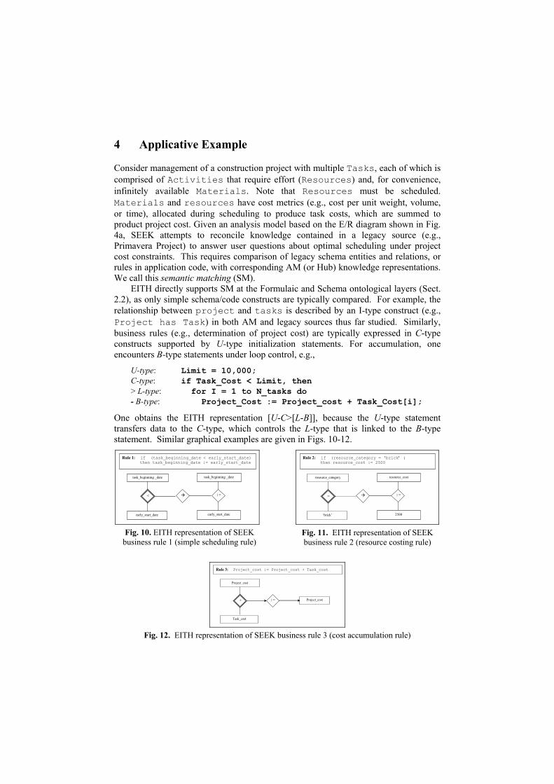
EITH directly supports SM at the Formulaic and Schema ontological layers (Sect. 2.2), as only simple schema/code constructs are typically compared. For example, the relationship between project and tasks is described by an I-type construct (e.g., Project has Task) in both AM and legacy sources thus far studied. Similarly, business rules (e.g., determination of project cost) are typically expressed in C-type constructs supported by U-type initialization statements. For accumulation, one encounters B-type statements under loop control, e.g.,
U-type: Limit = 10,000; C-type: if Task_Cost < Limit, then > L-type: for I = 1 to N_tasks do - B-type: Project_Cost := Project_cost + Task_Cost[i];
One obtains the EITH representation [U-C>[L-B]], because the U-type statement transfers data to the C-type, which controls the L-type that is linked to the B-type statement. Similar graphical examples are given in Figs. 10-12.
task_beginning _date
< :=
task_beginning _date
early_start_date early_start_date
Rule 1: if (task_beginning_date < early_start_date) then task_beginning_date := early_start_date
Fig. 10. EITH representation of SEEK
business rule 1 (simple scheduling rule)
resource_category
= :=
resource_cost
2500 ‘brick’
Rule 2: if (resource_category = ‘brick’ ) then resource_cost := 2500
Fig. 11. EITH representation of SEEK business rule 2 (resource costing rule)
Project_cost
+ := Project_cost
Task_cost
Rule 3: Project_cost := Project_cost + Task_cost
Fig. 12. EITH representation of SEEK business rule 3 (cost accumulation rule)

5 Comparison of Complex Structures with EITH
Published research indicates that complex constructs occur infrequently in legacy sources, and their interpretation or comparison often requires human expertise. We are currently developing theory and algorithms to address the problem of (1) identifying complex structures in an AST representation A of database schema and code, then (2) partitioning them into EITH-representable sequences to be (3) compared using a schema structure similarity metric [8]. This would allow large sources (e.g., 103 to 105 relations and 104 to 107 lines of code) to be accommodated in SEEK.
In particular, after Step 1 traverses A, bidirectionally indexing all nodes to a symbol table SD, and Step 2 similarly builds a structure table SS, then Step 3 does the following: a) Compares a legacy structure sL with an AM structure sA, by first lexically
comparing all sL nodes with all sA nodes using SD (e.g., compare legacy table name Task_MSP with AM table name Task), resulting in a node score Mnd(sL,sA) .
b) Compares the EITH-encoded structure of sL (from structure table SS) with that of sA, to yield a structure metric Mst(sL,sA).
c) Mst is combined with Mnd to yield composite matching score M. d) Matches with high M are reviewed by a domain expert; this knowledge is
accumulated to eventually support more automated processing. e) If the list of M-scores indicates inconclusive match, then a partition of SS is
queried using Mst scores derived from comparisons of all sL’s with sA that have high Mnd scores, to find subtrees of A which structurally resemble sA.
Because SD and SS are constructed at build-time, and because Steps 1-3 are build-time activities, the computational complexity is less important than for runtime processing. Our research indicates that EITH helps decrease computational costs and increases comparison accuracy, versus traditional AST traversal and subtree comparison approaches. Additionally, EITH facilitates comparison of business rules across multiple programming languages (PLs), due to the use of the parse tree as a unifying construct. That is, the parse tree of a business rule expressed at the statement level (e.g., if..then..else statement) has the same form whether the rule is written in Java, C, Pascal, or FORTRAN. This concept is basic to PL translation in software reverse engineering applications [17] as well as in program comparison systems such as the well-known moss plagiarism detection program.
6 Conclusion
We have presented a novel formalism called EITH that unifies the representation of database schema and application code. EITH can be efficiently derived from various types of schema representations, particularly the relational model, and supports comparison of a wide variety of schema and code constructs (e.g., relations, relationship relations, assignment, arithmetic, or flow control statements). Unlike UML or E/R diagrams, for example, EITH has compact notation, is unambiguous, and uses a small set of efficient heuristics. We have shown how EITH is employed in the context of SEEK, using a construction project management example. We have also shown how

EITH can represent various structures in relational databases, and can serve as an efficient representation for E/R diagrams. We believe that EITH can support efficient matching of more complex, hierarchical structures via indexed tree representations, without compromising the EITH design philosophy or formalism. We are currently in the process of integrating EITH with the SEEK toolkit to demonstrate its usefulness in the context of legacy system integration.
References 1. D. C. Atkinson and W. G. Griswold, "The design of whole-program analysis tools," 18th
International Conference on Software Engineering, 1996. 2. S. Chawathe, H. Garcia-Molina, J. Hammer, K. Ireland, Y. Papakonstantinou, J. Ullman,
and J. Widom, "The TSIMMIS Project: Integration of Heterogeneous Information Sources," 10th Meeting of the Information Processing Society of Japan, Tokyo, Japan, 1994.
3. J. Ferrante, K. J. Ottenstein, and J. D. Warren, "The program dependence graph and its uses in optimization," ACM TOPLS, vol. 9, pp. 319-349, 1987.
4. L. Haas, R. J. Miller, B. Niswonger, M. T. Roth, P. M. Schwarz, and E. L. Wimmers, "Transforming heterogeneous data with database middleware: Beyond integration.," IEEE Data Engineering Bulletin, vol. 22, pp. 31-36, 1999.
5. M. Hall, J. M. M. Crummey, A. Carle, and R. G. Rodriguez, "FIAT: A framework for interprocedural analysis and transformations," 6th Workshop on Languages and Compilers for Parallel Computing, 1993.
6. J. Hammer, M. Breunig, H. Garcia-Molina, S. Nestorov, V. Vassalos, and R. Yerneni, "Template-Based Wrappers in the TSIMMIS System," Twenty-Third ACM SIGMOD International Conference on Management of Data, Tucson, Arizona, 1997.
7. J. Hammer, H. Garcia-Molina, S. Nestorov, R. Yerneni, M. Breunig, and V. Vassalos, "Template-Based Wrappers in the TSIMMIS System," SIGMOD Record (ACM Special Interest Group on Management of Data), vol. 26, pp. 532-535, 1997.
8. J. Hammer and C. Pluempitiwiriyawej, "Element Matching across Data-oriented XML Sources using a Multi-strategy Clustering Technique," Data and Knowledge Engineering (DKE), Elsevier Science, 2004.
9. J. Hammer, M. Schmalz, W. O'Brien, S. Shekar, and N. Haldavnekar, "SEEKing Knowledge in Legacy Information Systems to Support Interoperability," ECAI-02 International Workshop on Ontologies and Semantic Interoperability, Lyon, France, 2002.
10. W. O'Brien, R. R. Issa, J. Hammer, M. S. Schmalz, J. Geunes, and S. X. Bai, "SEEK: Accomplishing Enterprise Information Integration Across Heterogeneous Sources," ITCON - Journal of Information Technology in Construction, vol. 7, pp. 101-124, 2002.
11. S. Paul and A. Prakash, "A Framework for Source Code Search Using Program Patterns," Software Engineering, vol. 20, pp. 463-475, 1994.
12. K. Pingali, M. Beck, R. Johnson, M. Moudgill, and P. Stodghill, "Dependence Flow Graphs: An Algebraic Approach to Program Dependencies," 18th ACM Symposium on Principles of Programming Languages, 1991.
13. Rational Software Corp., Unified Modeling Language Summary 1.1, 1997. 14. S. Shekar, J. Hammer, and M. Schmalz, "Extracting Meaning from Legacy Code through
Pattern Matching," Department of CISE, University of Florida, Gainesville, FL 32611-6120, TR03-003, January 2003.
15. A. Sheth and J. A. Larson, "Federated Database Systems for Managing Distributed, Heterogeneous, and Autonomous Databases," ACM Computing Surveys, vol. 22, pp. 183-236, 1990.
16. G. Wiederhold, "Weaving data into information," Database Programming and Design, vol. 11, 1998.
17. L. Willis and P. Newcomp, "Reverse Engineering." Boston, MA: Kluwer, 1996.