Embed Size (px)
Citation preview

eiuesa empresa nacional de residuos radiactivos, s.a.
_ _ £sJSB \-
THE DISPOSAL OF HIGH LEVEL RADIOACTIVE WASTE
IN ARGILLACEOUS HOST ROCKS
IDENTIFICATION OF PARAMETERS, CONSTRAINTS AND GEOLOGICAL
ASSESSMENT PRIORITIES
PUBLICACIÓN TÉCNICA NUM. 04/94

THE DISPOSAL OF HIGH LEVEL RADIOACTIVE WASTE
IN ARGILLACEOUS HOST ROCKS
IDENTIFICATION OF PARAMETERS, CONSTRAINTS AND GEOLOGICAL
ASSESSMENT PRIORITIES
S. T. Horseman
ÍNTERA - ENVIRONMENTAL DIVISION

THE DISPOSAL OF HIGH LEVEL RADIOACTIVE WASTE
IN ARGILLACEOUS HOST ROCKS
IDENTIFICATION OF PARAMETERS, CONSTRAINTS AND GEOLOGICAL
ASSESSMENT PRIORITIES
This report has been drawn up on behalf of ENRESA. It represents the opinion of the contractor which need not necessarily
coincide with that of ENRESA in every respect.

Executive Summary
EXECUTIVE SUMMARY
li

Executive Summary
The purpose of this report, commissioned by ENRESA, is to examine the characteristics, properties and responses of argillaceous media (clays and more indurated mudrocks) in some detail in order to identify the main parameters that will influence the radiological safety of a deep underground facility for the disposal of high-level radioactive wastes (HLW) and to highlight possible constraints and other important issues relating to the construction, operation and performance of such a facility.
The observations and conclusions of the report are drawn together to provide recommendations and practical guidelines for the geological assessment of potential host formations, including numerical modelling approaches and priorities for supportive R&D studies. The report does not consider "generic" site characterization methods (e.g. geophysical techniques, geological mapping etc.), since these are 1. >i specific to argillaceous media.
From the geological perspective, argillaceous rocks (= mudrocks) encompass a wide variety of Iithotypes ranging from soft clays, through more indurated types such as the mudstones, claystones and clayshales, to hard metamorphic rocks such as argillite and slate. The character and properties of these rocks depend, to a large extent, on their burial history and on the degree of diagenetic alteration which has occurred during burial. Mudrocks which have suffered minimal diagenetic alteration have the attributes of high water content and low strength and •will tend to fail by plastic flow, rather than by brittle fracture. At the other end of the spectrum, highly altered and possibly metamorphosed mudrocks have very low water contents and high strengths and display the brittle fracturing characteristics typical of all hard rocks deformed at shallow depths in the earth's crust.
Degree of diagenetic alteration during burial is a key factor which distinguishes one potential argillaceous host-rock from another, and the position of a particular host-rock within this spectrum will determine its main characteristics as a barrier to radionuclide migration and as a construction material. The less indurated rocks will deform largely in a plastic manner and will tend to self-heal if fractures do develop. "While these characteristics are very beneficial in terms of their overall effect in limiting radionuclide migration, the very same properties of high plasticity, low strength and capacity to swell will create difficulties and constraints in repository engineering. At the opposite end of the spectrum, self-healing and swelling are not characteristics of highly indurated argillaceous rocks and their overall
performance, as host-media, will be similar to that of hard, fractured, crystalline rocks.
However, the character and properties of many mudrocks are not exclusively determined by burial diagenesis, since a number of geological processes occurring subsequent to burial can play an important part in determining the structural attributes of these rocks (e.g. faults, folds, joints and fissures). The most important of these are tectonic deformation, uplift and exhumation and, not infrequently, all three processes are closely interrelated as surface erosion strips away sediments thrown up by large-scale deformation, bringing the niudrock stratum closer to the surface. The combined effect of these processes are to impose a "stress history" on the mudrock and it is this history which is the second major modifier of the character and properties of some potential argillaceous host-rocks. In some "tectonized" mudrocks, this stress history may be exceedingly complex and almost impossible to unravel. In other mudrocks which have been subject to a simple cycle of burial and exhumation, it is possible to reconstruct the stress history and use it to predict some of the main attributes and properties of the rock. The term "overconsolidated" is often applied to mudrocks which are presently at a depth which is less than the maximum burial depth and the water content, strength, plasticity and rock-mass characteristics (joints and fissures) of overconsolidated mudrocks are a more or less quantifiable function of their stress history.
Stress history is not only an important modifier of mudrock properties, it may also have a dominant effect on the hydrogeology of low permeability argillaceous sequences. In recent years an increasing amount of evidence has been presented that groundwater flow in some low permeability environments does not occur under steady-state conditions. This has significant implications in hydrogeological modelling. The main reason for non-steady state (transient) flow in thick sequences of low permeability rocks is the phenomenon of hydro-mechanical coupling, whereby changes in pore pressure are occasioned by changes in stress. Expressed in simple terms, the groundwater flow in such environments is a function of the stress history. The enormous difficulty of predicting flow in mudrocks subject to a complex history of stress (e.g. tectonized mudrocks) is immediate apparent.
In a simple geological environment, such as a gradually subsiding continental basin, with no evidence of recent uplift, major erosion episodes, ice-loading or neotectonic activity, the occurrence of
III

Executive Summary
long-term transient flow within the argillaceous sequence may not be a matter of concern.
The prediction of groundwater flow in argillaceous formation may not be straightforward even in this simple geological setting, since there is also evidence to suggest that the flux of water in such media may not be exclusively a function of thj hydraulic potential (head) gradient, or in simple terms, that Darcy's law, which is the basic premise of all hydrogeological modelling, is not valid for mudrocks. The assertion is that the groundwater flux is driven, in part, by other potential gradients and that the phenomenon of "coupled flow" is important. Movement of water by "nonconjugate" thermodynamic forces (i.e. potential gradients) is given the general name "osmosis" and, in normal geological situations, chemico-osmosis is considered to be the most important of the non-hydraulic mechanisms. In the near-field of a repository it seems likely that groundwater would also move down the temperature gradient around the heat-emitting waste by the mechanism of thermo-osmosis
The physical explanation ot coupled flow, "membrane effects" and many other important phenomena observed in clay systems lies in the generally large specific surface of clay minerals, the very small dimensions of the pores, and the complex interactions which occur between the ciay mineral particles, water molecules and dissolved chemical species. These are of the utmost importance in determining the overall performance of the argillaceous medium as a barrier to radionuclide migration.
Clay-water-solute interactions have a dominant effect on advective and diffusive mass transport in mud- rocks and are a key consideration in specific mechanisms of radionuclide retention and retardation such as cation exchange and anion exclusion.
The surfaces of clay minerals within a mudrock have a negative charge which attracts cationic species and water to them to form adsorbed "double-layers". In the more compact mudrocks, most of the water present is strongly adsorbed in these double-layers and very little can participate in normal advection. The interaction of double-layers in compact clays and mudrocks results in very large forces of repulsion between their constituent clay particles and these are partly responsible for the marked swelling of these materials when they are de-stressed and exposed to fresh water. The forces of repulsion also act in a mudrock under in situ conditions, representing one of several forces acting between particles which enable the mudrock to support the weight of overlying formations. The sources of these forces of
IV
repulsion are the hydration of clay surfaces and of adsorbed cations and the osmotic pressure between the adsorbed aqueous solutions and free (macropore) water. An important conclusion of this report is that any change of the local chemical and physical environment of the mudrock (e.g. stress, pore pressure, chemistry and temperature) will alter the relative magnitude of these forces of repulsion causing knock-on effects in other areas. This is the source of a very complex coupling between the thermal, chemical, hydraulic and mechanical responses of a mudrock. Osmosis represents only one facet of this complicated behaviour.
It seems probable that non-hydraulic mechanisms of groundwater flow will become more important as the ratio of the mass of adsorbed water to the mass of free water increases. Thus, although the groundwater flow velocities in more indurated and compact mudrocks (e.g. clayshales) are likely to be smaller than in the less-indurated clays, the mechanisms of groundwater movement are likely to be more complex in the more compact rock.
Borehole effects, including swelling and closely related chemico-osmotic flow, have been invoked to explain the anomalous hydraulic potentials (heads) which have been observed in a number of potential argillaceous host-rocks in Switzerland and elsewhere.
If standard techniques are used (i.e. fresh water as a test fluid) to characterize the hydrogeology of the argillaceous formations, then it must be recognized that there are very major doubts as to the exact meaning of the test data. Three possible approaches are available:
a) ignore these effects and recognize that the interpretation may be suspect,
b) use standard techniques only in the non--argillaceous units or,
c) institute a programme of research aimed at developing more suitable testing techniques for argillaceous rocks, possibly with water chemistry as a test variable.
The latter option has been recommended to NAGRA (Horseman et al. 1991).
Given the difficulties associated with the hydrogeological characterization of low permeability argillaceous rocks, considerable emphasis should be placed on geochemical methods of investigation. Hydrochemical methods (e.g. environmental isotope analysis) have considerable potential to define the main characteristics of the hydrogeological system and to provide valuable data on such issues as

Executive Summary
groundwater age, flow-path and residence time. It is possible that geochemical methods will ultimately provide far more convincing evidence of Ihe performance of the barrier than can be obtained by hydraulic testing and groundwater flow modelling.
The degree of sophistication of the groundwater analytical programme should be commensurate both with the quality of water samples available from the field programme and with the level of understanding of the regional geology and hydrogeology. The analysis of environmental isotopes demands the highest quality water samples and a partial suite of isotopes might be examined in early-stage assessment.
In order to obtain good quality water samples and to allow the monitoring (or the research) of hydraulic responses, the installation of a permanent, multi-sectional, borehole completion is recommended in one or more of the ENRESA exploratory boreholes. This could be the Westbay-type or of a similar design. The volume of groundwater samples necessary for particular analytical procedures is an important consideration in establishing sampling methods and in the design of the permanent completion.
General data acquisition priorities can be established by examining the main requirements of the geological barrier. These requirements may be summarized as:
a) to provide a low flow near-field environment for disposal which will reduce the rate of degradation of the man-made barriers and limit the mobility of radionuclides in the near-field,
b) to attenuate the flux of radionuclides migrating through the barrier by the processes of sorption, filtration, radioactive decay and dilution, in combination with low rates of advective and/or diffusive transport and,
c) to provide migration paths which are sufficiently long that, at some distance into the barrier, the flux is so attenuated that the migration of radionuclides beyond this point does not, at any time, constitute a hazard to man.
Thus the ideal, which may be attainable in argillaceous media, is total containment within the barrier. Since the mass transport properties of the barrier depend >m the physical and chemical characteristics of the formation, these complicated requirements can be translated in simple geological guidelines. The key geological factors likely to affect ihe performance of an argillaceous formation as a barrier are:
• Depth and thickness • Proximity to more permeable, water-bearing
strata • Heterogeneity (silly/sandy interbeds, lenses,
etc.) • Discontinuities (faults, joints, fissures, etc.)
• Mineralogy (% clay, bulk and clay mineralogy, organics, etc.)
• Porewater chemistry (pH, Eh, organics, etc.) B Degree of diagenetic alteration (plasticity,
compaction, etc.)
• Burial and stress history (loading/unloading, etc.)
Detailed knowledge of lithological, chemical and physical property variations with depth is therefore necessary in order to characterize fully the geological barrier, to assist hydrochemical interpretation and to identify geotechnical constraints. This will require good quality core samples (including some "undisturbed" samples) to be taken at regular intervals (initially = 5 m) down each borehole so that property profiles can be established. Fundamental laboratory tests and analyses relate to particle size distribution, mineralogy and petrography (including % clay and clay minerals), whole-rock chemistry, specific surface, density, water content and degree of saturation, porosity, permeability and pore size distribution. Mudrock samples should be squeezed to expel porefluids for chemical analysis, and similar data might be obtained in other rocks by centrifuging or leaching. Some samples might also be taken for radionuclide diffusion and sorption experiments, although there may be reservations about performing these complex tests during early-stage geological appraisal.
Most of the properties and parameters listed above are also of interest in geotechnical assessment. Additional tests, with specific geotechnical applications, are the Atterberg limits (in softer clays and mudrocks), undrained shear strength (or uniaxial compressive strength), consolidation properties, including hydraulic conductivity, preconsolidation stress and overconsolidation ratio (OCR), and the swelling properties. More sophisticated studies of the effective strength parameters, stress-strain relationships, residual strength, thermal parameters, thermo-mechanical behaviour, mudrock breakdown and thermal degradation of minerals might be contemplated on a few samples. Some geophysical properties might also be determined to aid log calibration.
V

Executive Summary
The best approach to data handling and manipulation is to hold all the borehole information, including the geological logs, in a computerized database so that properties can be interrelated with ease and can be plotted against depth, greatly facilitating the interpretation and presentation of data. Databasing and interactive processing using computer workstations and appropriate software is recommended for other geological information, including regional geophysical data, borehole (wireline) geophysical data, hydrogeological and hydrochemical data and all interpretations stemming from these b¿isic data sets.
The assessment of the regional groundwater flow would generally require that numerical modelling be undertaken. Given the uncertainties associated with the modelling of mudrock environments, it seems unwise to devote large resources to this activity before the mechanisms have been clarified. Far more can be learned from relatively simple scoping calculation of radionuclide transport assuming worst-, probable- and best-case groundwater flow scenarios. Generic mudrock sorption and diffusion parameters for critical radionuclides (e.g. :od';ie) could be assumed, and release to biosphere could be assumed to occur at a critically-located drinking water-well (i.e. water-well calculations). A suitable probabilistic risk assessment (PRA) code (e.g. VANDAL) could easily be set up to perform these calculations on a routine basis, with regular data upgrades as more field information is obtained. Consideration should also be given to migration pathways other than the groundwater pathway since geological factors will also have an impact in these areas.
Two basic engineering concepts are available for the disposal of highly active wastes in argillaceous media:
• Mined repository (system of tunnels or galleries)
B Deep borehole facility (DBF)
The main distinction between the mined repository and the deep borehole facility (DBF) is the capacity of the former to handle large volume waste categories. The DBF can only really be contemplated for certain low volume waste categories. The advantages of the DBF are its flexible and modular nature, the less stringent depth constraints and the significantly lower construction cost.
Geotechnical characteristics of the weaker argillaceous rocks, together with the economics of construction, place a limit on the depth of a mined repository.
A number of specific issues relating to the disposal of heat-emitting waste in argillaceous rocks have been identified:
a) thermal responses,
b) gas transport properties and
c) specific geotechnical problems.
Although the duration of the thermal phase may be comparatively short when judged against the total performance assessment time-scale, the increase in temperature associated with radiogenic heat can have quite significant effects, largely in the near-field of the repository, but possibly extending beyond the argillaceous host-rock to encompass other rock--types.
A maximum allowable temperature must be established, based on detailed studies of the thermo-mechanical and hydro-thermal responses of the host-rock and of the thermal stability of the buffer/backfill and host-rock mineral assemblages. Due to the generally lower thermal conductivity of mudrocks compared to other potential host-rocks and the lower maximum allowable temperature, the thermal loading of the repository must be lower than would be acceptable for other rocks. In effect, the waste canisters must be more widely spaced in the mudrock.
One particular effect, which is of particular concern, is the development of very high, thermally-induced, pore pressures within the host-rock. Calculations and laboratory experiments suggest that the perturbed pore pressures could, in the worst case, approach the magnitude of the total stress. This could have profound effects on the shear strength of joints, fissures and incipient failure planes, on tunnel lining loads and on the stability of unlined waste emplacement boreholes.
Other possibly troublesome thermal effects close to the waste are a reduction in water content and associated development of shrinkage cracks, the thermo-osmotic and thermo-diffusive transport of porewater and solutes down the thermal gradient, possible alteration of the clay minerals, and changes in the interparticle and interlayer forces of repulsion (e.g. loss of swelling pressure). Since the canisters will probably be intact during the thermal phase, the main concern is that the transport properties of the host-rock or the clay buffer/backfill might be irreversibly affected by these mechanisms.
If the thermal field extends beyond the argillaceous host to encompass other more permeable formations,
VI

Executive Summary
then there is a possibility that groundwater flow will be perturbed by the mechanism of thermo-convection.
In plastic clays and other tight mudrocks, gas production within the repository is likely to be an important issue, since these rocks cannot easily accommodate the gas flux. The build-up of gas pressure is the main issue, since it is probably impossible to construct high integrity seals that could withstand a differential pressure for any significant length of time and there is the possibility that gas might migrate along the backfilled tunnels and shafts, pushing contaminated groundwater with it. If gas production is likely to be significant, then its possible
repercussions should examined in detail at an early stage.
Finally, specific geotechnical problems could be encountered in developing a disposal facility in certain geological settings and rock-types. Abnormal stress conditions may be encountered in highly tectonized mudrocks and underground construction in such a setting could be very problematic. Tunnelling in high swelling clays and mudrocks can also present major difficulties, including substantial inward movements ("heave") of the rock during excavation and the severe overload of temporary support systems and permanent linings.
VII

/I Contents
CONTENTS
¿

Contents
1. INTRODUCTION 1
1.1 Classification of Argillaceous Rocks 4
2. REQUIREMENTS 7
2.1 Minimizing Radiological Risk 9
2.2 Meeting Operational Requirements 10
2.3 Economics of Construction and Operation 10
2.4 Implications for Site Assessment 12
3. DISPOSAL CONCEPTS 13
3.1 Multiple Barrier Concept 15
3.2 Mined Repository 16
3.3 Deep Borehole Facility (DBF) 17
3.4 Relative Merits of the Disposal Options 18
3.5 Constraints on Disposal 19
4. GEOLOGICAL ENVIRONMENT 21
4.1 Sources of Clay Minerals 23
4.2 Clay Minerals at the Time of Deposition 24
4.3 Lacustrine Sedimentology 24
4.4 Burial Diagenesis 24
4.4.1 Compaction and Fluid Migration 24
4.4.2 Clay Mineral Transformations 25
4.4.3 Geochemical Processes 26
4.5 Stress History and Overconsolidation 28
4.6 Quantitative Analysis of Burial History 31
4.7 Discontinuities 31
4.8 Loss of Overconsolidation and Physical Breakdown 33
5. CLAY-WATER-SOLUTE SYSTEM 35
5.1 Clay Minerals 37 5.1.1 Two-Layer Sheets 37 5.1.2 Three-Layer Sheets 37 5.1.3 Disorder in the Clay Mineral Lattice 39
5.2 Adsorption and the Gouy Double-Layer 40
5.3 Cation Exchange 40
XI

Contents
5.4 Anion Exchange 41
5.5 Double-Layer Theory 41
5.6 Significance of the Interparticle Forces 41
5.7 Properties of Water near Clay Particles 42
5.8 Membrane Effects and Anion Exclusion 43
6. HYDROGEOLOGY 45
6.1 Is Mudrock Hydrogeology Important? 49
6.2 Basic Hydrogeological Parameters 50
6.2.1 Potentials, Heads and Pore Pressures 50 6.2.2 Total and Effective (Flowing) Porosity 51 6.2.3 Permeability and Hydraulic Conductivity 52 6.2.4 Predicting Intrinsic Permeability 54
6.3 Non-Darcy Flow 55
6.4 Coupled Flow Phenomena 55
6.5 Transient Flow 56
6.6 Effect of Layering on Regional Flow 57
6.7 Role of Faults in Regional Flow 57
6.8 Hydraulic Testing 57
7. GEOCHEMISTRY 59
7.1 Hydrochemistry 61 7.1.1 Hydrochemical Programme 61 7.1.2 Groundwater Sampling 62 7.1.3 Extraction of Porewater/Solutes from Core Samples 63 7.1.4 Chemical Equilibrium Modelling 63 7.1.5 Environmental Isotope Analysis 63
7.2 Mineralogy, Petrology and Chemistry 64 7.2.1 Analytical Techniques 64 7.2.2 Geochemical Studies of Fractures in Mudrocks 65
8. RADIONUCLIDE MIGRATION 67
8.1 Radionuclides 69
8.2 Radionuclide Transport in Mudrocks 69
8.2.1 Factors Affecting Transport 69 8.2.2 Radionuclide Speciation 72 8.2.3 Effects of Near-Field Evolution 73
Xll

Contents
8.3 Advection/Dispersion Model 74 8.3.1 Dispersion 74 8.3.2 Advection Term 75 8.3.3 Dispersion Term 75 8.3.4 Radioactive Decay Terms 76 8.3.5 Transport Equation for Non-Sorbing Species 76 8.3.6 Sorption and the Distribution Coefficient 76 8.3.7 Transport Equation including Sorption 76 8.3.8 Source Term 77
8.3.9 Solutions 77 8.4 Diffusion in Mudrocks 77
9. GASES AND GAS MIGRATION 79
9.1 Gas Generation 81 9.1.1 Corrosion 81 9.1.2 Radiolysis 83 9.1.3 Microbial and Chemical Degradation of Organics 83 9.1.4 Other Mechanisms 83
9.2 Gas Migration in Mudrocks 83
9.3 G&neral Implications of Gases 84
10.THERMAL PROPERTIES AND RESPONSES 85
10.1 Geothermal Temperatures 87
10.2 Maximum Allowable Temperature 87
10.3 Heat Transport 87
10.4 Thermal Properties 88
10.5 Thermally-Induced Pore Pressures 89
10.6 Heating, Drying and Shrinkage 93
10.7 Thermo-Osmosis 94
10.8 Thermo-Diffusion 94
10.9 Thermal Stability of Minerals 94
11.GEOTECHNICAL CONSIDERATIONS 97
11.1 Geotechnical Properties of Mudrocks 99 11.1.1 Basic Properties 100 11.1.2 Strength Properties 100 11.1.3 Deformation Properties 102
XIII

mm* Contents
11.1.4 Significance of Fissuring 102 11.1.5 Consolidation 102 11.1.6 Rheological Behaviour 103 11.1.7 Swelling 103
11.2 Tunnelling Stability Indices 104
11.3 Tunnelling Conditions in More Indurated Mudrocks 105
11.4 Borehole Stability 106
11.5 Exploratory Drilling in Mudrocks 106
11.6 Undisturbed Samples 107
11.7 Sample Preservation and Storage 108
12.CONCLUSIONS, GUIDELINES AND RECOMMENDATIONS 109 12.1 Geological Assessment Priorities 111
12.2 Important Host-Rock Characteristics 113
12.3 Disposal Concepts 115
12.4 Some Important Issues 115
13.REFERENCES 117
XIV

1. Introduction
1 INTRODUCTION
72.

Approximately 33% of the electricity used in Spain conies from nuclear power plants. Spain has 9 nuclear reactors on line, with a total capacity at the end of 1992 of 7,4 Gigawatts. With the exception of Vandellos 1, a gas-cooled reactor (GCR) now under dismantling process, all the nuclear power plants are of the light water type, including 7 pressurized water reactors (PWR) and 2 boiling water reactors (BWR).
Although reprocessing is not presently contemplated in Spain and spent fuel from nuclear power plants will be stored until its final disposal, due to its special characteristics, spent fuel from the Vandellos I gas-cooled reactor is being sent abroad for reprocessing (OECD/NEA, 1988).
Along with the development of interim storage systems for spent fuel, ENRESA has initiated a programme to investigate the final disposal of this type of waste, together with the small volumes of vitrified products arising from reprocessing operations. These are highly active, long-lived wastes with a significant [.¿at output. rihe disposal concept presently under examination is luirial in a deep geological formation (Ministry of Industry and Energy, 1989).
Unlike many European countries, the geology of Spain is sufficiently diverse that a variety of potential host-rocks and geological settings for a disposal facility can be identified. The three possibilities are:
a) crystalline rock masses, primarily granite or granitoid rocks,
b) saliferous formations including salt diapirs and,
c) argillaceous formations such as clays, marls and shales.
Each of these possibilities is under examination in various countries outside Spain and in some cases these studies are by now well-advanced. Canada, Sweden, Switzerland, Finland, France and Britain have programmes examining the potential of a variety of hard crystalline rocks for the disposal of radioactive wastes. Germany, Holland and Denmark are investigating disposal in salt formations, France is retaining salt as an option and, although DoE in the USA has abandoned the salt repository concept for civilian waste in favour of the volcanic rocks of Yucca Mountain, Nevada, the WIPP salt repository in New Mexico is presently seeking a licence to accept defence waste. Belgium, France and Switzerland are examining disposal in argillaceous rocks and the results of the long-running Belgian programme investigating the Oligocene Boom Clay are of particular interest in the context of this report.
1. Introduction
International experience, to date, is that no single rock-type offers such distinct and wide-ranging advantages over others that the choice of host-rock can be easily made on a generic basis. One rock-type may be excellent from the geotechnical perspective, offering good conditions for repository construction, but this advantage may be outweighed by the higher level of uncertainties in predicting groundwater flow. Another rock-type may offer the prospect of very good long-term containment, but its mechanical responses may be such that repository engineering is both difficult and expensive and retrievability, which is required in some countries, may be hard to guarantee.
As part of a wider programme within the European Community (EC), aimed at producing a catalogue of European formations with favourable characteristics for radioactive waste disposal, the IFA Project was set up by ENRESA in 1986 to identify and document all those geological formations in Spain that, a priori, presented sufficiently favourable conditions tc warrant more detailed examin^ion. General geological selection criteria were established as part of this exercise. The main output of the IFA Project was the National Inventory of Favourable Formations (ENRESA, 1988).
This first phase of the site selection process identified, along with the other host-rock possibilities, six major sedimentary structures in Spain containing argillaceous sequences with characteristics that satisfied the initial selection criteria. These were the Duero, Ebro, Tagus and Guadalquivir Basins, the Pyrenees and the Cantabrian region.
Although a number of sedimentary structures have been drilled by the oil companies in the search for petroleum, seismic survey coverage is often poor and in many areas of the Spanish interior the subsurface geology cannot yet be defined in any detail. Where formations are not exposed at the surface, or are poorly exposed due to an absence of topographical features, very little may be known about the character and properties of these rocks. This presents quite significant problems in assessing their potential as host-rocks.
Following preparation of the National Inventory, the selection process continued with the filtering of possibilities on a regional basis using socio-economic and other internationally-accepted selection criteria (Ministry of Industry and Energy, 1989). Specific formations were then identified for more detailed examination in the next stage of the process which was known as the ERA Project (High Level Regional Studies).
3

1. Introduction
"Within the work programme on argillaceous hosl-rock options, effort is presently focused on two of the sedimentary basins, both of Tertiary age. The Duero Basin of north-central Spain lies to the south of the Cordillera Cantábrica and north of the Central System and extends east from the city of Zamora to the Demanda mountains covering an area of approximately 55,000 km2. The Ebro Basin of north-eastern Spain lies between the Pyrenean foothills to the north-east and the Cordillera Ibérica to the south-west, with the city of Zaragosa at its centre, and covers an area of 34,000 km2.
In examining the comparative merits of an argillaceous host-rock we are concerned not only with the advantages that the rock-type can offer, but also the constraints and potential problems. Some of these issues can be examined on a generic basis, guided by the substantial published literature on clays and other mudrocks and drawing on the experience gained in other programmes which are examining their potential as host-media. It is important tMat such available information be compiled and fully analyzed at an early stage, since it would be undesirable to commit large financial resources to investigating a particular issue when conclusive results were already available from some other programme.
However, many of these issues will depend on characteristics which are specific to the particular host-rock, the formation, or the regional geological setting. Fracturing, for example is usually very site-specific in character and its significance to radionuclide transport can only be assessed by field observations and measurements. Likewise, it not possible to make anything more than the most general statements on the issue of groundwater flow without reference to site-specific information.
The purpose of this report is to examine the characteristics, properties and responses of argillaceous media at a fundamental level in an effort to identify the main parameters that will influence the radiological safety of a deep disposal facility in these rocks and to highlight possible constraints and other important issues relating to the construction, operation and performance of such a facility. The observations and conclusions of the report are drawn together to provide recommendations and practical guidelines for the geological assessment of potential host formations, including numerical modelling approaches and priorities for supportive R&D studies. The report does not consider "generic" site characterization methods (e.g. geophysical techniques, geological mapping, etc.) which are widely applicable in all geological environments.
1.1 Classification of Argillaceous Rocks
From the geological perspective, argillaceous rocks encompass a very wide range of lithotypes ranging from unlithified muds and clays, through moderately indurated mudslones and claystones to fissile and often highly indurated shales and then, finally, to metamorphosed rocks such as slate. Across this wide spectrum, the characteristics and physical properties of argillaceous rocks vary enormously.
The term mudrock, which was coined by Ingram (1953), is widely used as a synonym for argillaceous rock and as a major class name for sedimentary rocks containing more than 50% of clay- or silt-sized grains with a particle size less than 63 Jim (Blatt et al. 1980; Stow, 1981).
Given the large variety of mudrocks, a number of geological and geotechnical classifications have been proposed. These include classifications by Wentworth (1922), Ingram (1953), Dunbar and Rogers (1957), Folk (1968), Picard (1971), Lewan (1978), Lundegard and Samuels (1980), Potter et al. (1980) and Blatt etal. (1980).
Classification of these rocks has yet to be fully standardized and a comparison of the existing systems of classification reveals a number of disagreements in the terminology and definitions. The classification shown in Table 1.1 appears to be the most useful and is based on Potter, Maynard and Pryor (1980), with term "clay" substituted for the original term "claymud" which is not widely used outside North America. Clay-sized particles are defined as the particle size fraction less than 2 Jim (or, alternatively 4 Jim on the Wentworth scale) and a mudrock is considered to be "laminated" if the separation between layers is less than 10 mm.
From the geotechnical perspective, argillaceous media at the weaker end of the strength spectrum are categorized as clay soils. The term clay (argile) is used in fairly non-specific way in the geotechnical and radioactive waste disposal literature to describe a more or less indurated soil/rock, with a predominance of clay minerals, which exhibits the mechanical attribute of plasticity. This usage is retained in this report, except where more specific terminology is required to clarify meaning. The term "overconsolidated clay" is applicable to many of the post-Palaeozoic clay formations in Europe and describes a clay that has, at some time in the past, been buried beneath a thickness of overburden which exceeds the present-day thickness.
4

1. Introduction
Table 1.1 Geological classification of mudrocks (slightly modified from Potter, Maynard and Pryor, 1980).
•
Non-indurated
Indurated
Metamorphoseds
. . . .
Beds
Laminae
Beds
Laminae
Low
Medium
High
Percent clay-size partid
0-32% -
Bedded Silt
Laminated cut
Siltstone
Siltshale
Quartz Argillite
Quartz Slate
33-65%
Bedded Mud
Laminated Mud
Mudstone
Mudshale
Argillite
Slate
5S
- 66-100% .
Bedded Clay 0
Laminated ClayO
Claystone
Clayshale
Argillite
Slate
Phylllte and/or Mica Schist
(*) Term "clay" substituted for "claymund" in original classification.

2. Requirements
REQUIREMENTS
'Ji

The geological requirements of a host formation can be established by analyzing the overall requirements of the disposal facility. These overall requirements may be summarized as:
• Meet long-term radiological safety requirements
• Fulfil operational requirements • Be economic to construct and operate Additional requirements may relate to local and
central government planning controls and land-use restrictions, non-radiological environmental impact, and the complex issue of public acceptability.
The adequacy of the proposal to construct a repository will be judged on the basis of how well the proposed scheme meets this set of requirements.
Radiological safety requirements are laid down by the regulatory authorities. These are couched in terms of the risk to the human population from exposure to radioactivity and may be expressed as targets or as mandatory upper limits. The time period over which this is to be assessed may, or may not, be explicitly stated.
2.1 Minimizing Radiological Risk An attempt to calculate the radiologic risk
associated with a particular disposal concept and site, even at the early stages of a site-assessment programme, can be an extremely enlightening exercise, since it highlights many of the major uncertainties associated with both the site and the concept. The application of probabilistic risk assessment (PRA) during site assessment is to be recommended. To some extent, the key sensitivities of a PRA analysis can be anticipated, leading to the following general observations and conclusions.
Calculation of radiological risk requires that all possible pathways to the biosphere, and hence to man, be identified. The complex processes governing the movement of radionuclides along these pathways must also be sufficiently well understood and quantified that reliable analyses of dose and risk can be made for extended time periods in the future.
The potential pathways of radionuclide release from the disposal facility to the biosphere are:
• Groundwater pathway • Gas transport pathway • Uplift/erosion/exhumation pathway • Human intrusion pathway • Low probability event pathway
2. Requirements
There is general agreement that transport in moving groundwater represents the single most important pathway by which radionuclides might enter the biosphere. This is the first and foremost consideration in selecting both the host-rock and the geological setting for the disposal facility and in the design of the underground facilities. The "multiple barrier concept", which specifically addresses the groundwater pathway, is discussed in Section 3.1.
Where potable water resources exist within the hydrogeological regime of a proposed disposal facility, the most direct potential pathway to man will often be through drinking water. Since the future exploitation of drinking water cannot be predicted, all sources of potable or near-potable v/ater are of concern regardless of whether they are currently used for supply purposes.
The avoidance of drinking water contamination is probably the most fundamental pre-requisite for long-term radiological safety. Since a disposal scheme that fails to protect water resources will have little chance of meeting statutory requirements, considerable emphasis must be placed on this issue at all stages of a programme
In examining the gas transport pathway, we are primarily concerned with the possible migration of active gases from the disposal facility to the biosphere. These gases may be produced directly by the waste or may be rendered radioactive by the process of isotopic exchange (e.g. 14C for 12C). Non-active gases may also be produced and are also of concern since they may carry a charge of active gases and could, potentially, influence radionuclide migration along other pathways.
The main concern under the heading of the "uplift/erosion/exhumation pathway" is that localized surface denudation by glaciers, rivers or the sea might reduce the thickness of the geological barrier or, in an extreme case, expose the waste-form. The main safeguards against this occurrence are to select a site with a low probability of localized erosion and to bury the waste at a depth which significantly exceeds the maximum conceivable erosion depth. In addressing this issue, an assessment is required of future climatic changes, sea level changes and isostatic re-adjustments of land surface elevation. Uplift due to diapirism is a problem specific to disposal in salt formations and, although the process is known to occur in deeply-buried shales, it is not likely to be a factor for argillaceous rocks, at typical repository depths, over the time-scale of interest.

2. Requirements
A wide variety of mechanisms have been proposed by which mankind, at some time in the future, might accidentally or deliberately penetrate or gain access to the waste in a repository, including drilling operations, mining and underground construction, geothermal energy and scrap recovery, to name but a few. It is possible to get into worthless circular arguments on human intrusion which distract from the main issues. The only general conclusions that might be made in relation lo the selection of a host formation is that known resources of drinking water, oil, gas, minerals and gcothcrmal licat arc best avoided so that the site arouses minimal future interest in terms of subsurface exploration, and that the repository should be located at sufficient depth to deter the malicious intruder.
The "low probability event pathway" is included here for the sake of completeness and includes a number of very low probability occurrences such as exhumation of the waste by a meteorite impact. Deep burial in a geological formation would seem to offer much better protection from such events than most alternative solutions to the problem of radioactive waste disposal. Furthermore, speculation on the consequences of such events, if they were to occur, must be kept in perspective in view of their far more drastic and widespread effects on society at large.
Because of the exceptional complexity of pathways within the biosphere and the difficulty of predicting future changes in surface environment, there is a considerable incentive to minimize the relative importance of biosphere processes and uncertainties in safety analysis. Although fairly self-evident, it is worth emphasizing that this means designing a disposal facility so that radioactive releases to the biosphere are so minimized that little or no reliance is placed on attenuation or dilution mechanisms in the biosphere.
2.2 Meeting Operational Requirements
The repository must meet the operational requirements. The most basic requirement is that it must be feasible to construct the underground facilities at an appropriate depth within the host-rock. The repository must also fulfil its function in terms of total volume and types of waste to be emplaced, the throughput and the operating lifespan. Health and safety requirements and other statutory demands must be met during the construction and operating period.
Feasibility of construction is primarily determined by the geotechnical and hydrogeo logical properties of the host-rock and overlying formations, together with interrelated economic considerations. Some key factors are the construction depth, rock-mass characteristics, rock strengths and deformabilities, in situ state of stress and potential groundwater inflows. All potential problems must be anticipated and, where it is possible to do so, difficult ground conditions should be avoided.
During the operational period, the best possible underground conditions are sought to facilitate the safe and efficient disposal of the waste. Given the importance of the facility and the general uncertainties in predicting the performance of any structures in rock, the design should be based on:
• High factors of safety • Conservative design principles • Well-established technologies
By emphasizing conservatism and a general reliance on well-established technologies for the excavation, support and operation of the underground facilities, the pitfalls of working "at the state of the art" will be avoided and at least some of the uncertainties on performance will be minimized.
2.3 Economics of Construction and Operation
Finally, the repository must be economic to construct and operate, since the cost of disposal of the waste from the nuclear fuel cycle should not impose an intolerable overhead on the cost of electricity generation.
The total cost of repository development will include the financial outlays on site characterization, basic R&D, modelling and validation, and safety assessment. At a geologically complex site, with a "difficult host-rock", the total up-front financial commitment may be very large and somewhat open-ended.
Construction costs are likely to vary significantly from one host-rock to another, depending on the selected disposal concept, the size of the facility and on the depth of the disposal horizon. Shaft freezing and large-scale grouting of water-bearing strata are likely to be expensive, if these are required. Tunnelling costs will also be high in weaker formations, and will increase substantially with depth.
10

2, Requirements
I A W _.. rtATIMfS u i r M j
HOSTSTRATUM
Too thin (<50 m)
Generally low
Frequent open joints, fissures, etc.
Frequent sandy/silty lenses or inter-beds
Very prone to chemical & thermal alteration
THICKNESS
CLAY CONTENT
DISCONTINUITIES
LENSES AND INTERBEDS
MINERAL ALTERATION
Very thick (>100 m)
Uniformly high
Few joints, fissures, etc. (mostly tight).
Frequent sandy/silty lenses or interbeds ,
Not prone to chemical & thermal alteration
SUCCESION '•••V':':-'-'
Mainly non-argillaceous
Steeply dipping
No high permeability units (e.g. aquifers)
LITHOLOGIES
ATTITUDE OF BEDS
PERMEABLE STRATA
Mainly argillaceous (or other low K rocks
Horizontal
No high permeability units
REGION
Frequent
Discontinous (fades changes, etc.)
Upward
Large-scale abstractions
Proven mineral deposits
Complex
History of significant events
Evidence of neo-tectonic activity
Mountainous
Potential for localized downcuttlng
FAULTING
LATERAL CONTINUITY
GROUNDWATER FLOW
DRINKING WATER
MINERALS
BASIN HISTORY
SEISMICITY
TECTONICS
TOPOGRAPHY
FUTURE EROSION
Infrequent (<1 per km)
Continous over large areas
Generally downard
No underground resources
No potential for minerals
Simple
No history of significant events
No evidence of neotectonlc activity
Flat or gently undulating
Localized downcutting unlikely
Figure 2.1 Simple qualitative rating system for argillaceous rocks aimed at optimizing the factors
which determine radiological safety and minimizing the complexity of safety assessment.
However, there is little doubt the major construction cost for a deep repository in argillaceous rock is the permanent lining. The deep borehole facility has definite cost benefits for certain types of waste (see Section 3.3).
Although operational costs may not be a prime consideration, the total outlay on backfilling, sealing and long-term monitoring of the disposal facility may not be insignificant.
11

2. Requirements
2.4 Implications for Site Assessment
The radiological safety requirements can be translated into some relatively simple guidelines relating to the site appraisal activities. Figure 2.1 shows an elementary, qualitative, rating system for the geological and geomorphological factors relating to potential argillaceous host-rocks and their regional setting. Maximum depth considerations and other gcotechnical issues, relating to the feasibility and economics of construction are not included, but are considered further in Chapter 11.
Most of the criteria for rating a host-rock are based on simple and fairly easily-determined attributes of the host stratum, the geological succession and the regional setting. A few criteria, such as the direction of groundwater flow and the issue of mineral stabi
lity, are more difficult to establish. The significance of specific issues, such as basin history, is examined in more detail in subsequent chapters.
The main point of this approach is that a potential site scoring a uniformly high rating will have been "optimized" in terms of the main factors contributing to the radiological safety. Furthermore, by emphasizing the requirement for a simple geological environment, the possible future task of demonstrating the radiological safety of the site will have been substantially simplified.
It would appear to be the case, based on presently available information, that simple sedimentary environments, associated with thick sequences of argillaceous rock, do exist in the Spanish interior. Other factors remain to be determimed.
12

3. Disposal Concepts
3 DISPOSAL CONCEPTS
13 A

3. Disposal Concepts
The multiple barrier concept is the cornerstone of all proposed schemes for the underground disposal of radioactive wastes. Based on the principle that uncertainties in performance can be minimized by conservatism in design, the concept invokes a series of barriers, both man-made and natural, between the waste and the surface environment, each successive barrier representing an additional impediment to the movement of radionuclides.
Two basic engineering concepts are available for the disposal of highly active wastes in argillaceous media:
it Mined repository (system of tunnels or galleries)
a Deep borehole facility (DBF)
The relative merits of these disposal options are briefly examined in this chapter and a number of constraints are identified. A more in-depth examination of the constraints is given in later chapters of the report.
3.1 Multiple Barrier Concept n the multiple barrier concept, the waste is larated from the surface environment (biosphere)
by a series of physical and chemical barriers, each of which acts as an impediment to radionuclide migration. Depending on waste category and disposal concept, the barriers are:
H Chemical barrier (conditioned waste) m Physical barrier (waste container) HI Engineered barrier (buffer/backfill, lining,
seals, etc.) a Geological barrier (low flow geological
environment)
Waste-conditioning provides the first, or innermost, barrier to radionuclide migration. The waste is incorporated in a stable and relatively inert matrix such as cement, bitumen, lead-alloy or polymer resin (L-ILW) or glass in the case of certain reprocessing wastes. Due to the very low leach-rate of glass in groundwater, vitrification is internationally accepted to be the best method of immobilizing the aqueous products from the reprocessing of spent fuel.
Although many waste containers will provide some form of physical barrier to groundwater, because of the relatively small volumes of waste involved, spent fuel, vitrified waste and other highly active wastes can be totally encapsulated in corrosion-resistant
metal canisters which are designed to prevent groundwater entry for extended time periods.
The functions of the engineered barriers are: a) to reduce the rate of corrosion and thus extend
the life of the waste containers,
b) to limit the release of radionuclides from the waste-form to the far-field (geosphere) after container failure and
c) to limit the migration of radionuclides along the pathway provided by the access tunnels and shafts of a repository or the boreholes in the case of a deep borehole emplacement.
Depending on disposal concept, the engineered barriers may comprise the buffer/backfill medium enclosing the waste containers, the tunnel/borehole liner, and the backfill and high integrity seals placed in the repository access ways or emplacement boreholes.
The buffer/backfill medium enclosing the waste will generally provide both a physical and a chemical barrier to radionuclide migration. Typically the buffer/backfill for HLW will comprise compacted bentonite or other clay-based material, giving a low permeability, an alkaline pH-buffered porewater which will limit the solubility and mobility of certain radionuclides (e.g. actinides), together with good retardation properties (high sorption and capacity to filter colloids).
The geological barrier is the final and most important impediment to radionuclide migration. Depending on details of the local geology, this may be considered to constitute the host formation itself (i.e. the clay stratum), extending above, below and laterally away from the repository or, alternatively, the entire sequence of low permeability rocks which may separate the repository from the surface and/or more permeable, water-bearing, strata.
With appropriate site-selection, this barrier will ensure a low flow environment for disposal, thus reducing the rate of degradation of the man-made barriers and limiting the release of radionuclides from the near-field. Furthermore, radionuclides migrating within the geological barrier will move extremely slowly in this low flow environment and the flux of radionuclides will be small and, importantly, will decrease along the migration pathway due to sorption on mineral phases, radioactive decay and dilution until, at some distance into the barrier, the flux is sufficiently attenuated that the migration of radionuclides beyond this point, perhaps to the surface environment (biosphere), does not at any
15

3. Disposal Concepts
COMPACTED CLAY SEAL
CHW CONTAINER
HLW CONTAINER
DISPOSAL HOLE COLLAR ¡
JNJECTED CLAYSLURRY/HCB PELLET BUFFER -,
-THIN CANISTER OVERPACK .1
'J -UNLINED DISPOSAL HOLE
[«,• SSSSESBSS' ">" <~ .
Figure 3.1 Schematic of HLW disposal in a mined repository
illustrating: a) the "ln-tunnel" concept and, b) the "In-floor" concept.
time constitute a hazard to man. The ideal, which may be achievable in the case of a clay host-medium, is total containment within the barrier.
The practical realization of the multiple barrier concept is the primary objective of all stages of a disposal programme, from site appraisal and characterization through to design and construction.
3.2 Mined Repository The construction of large disposal vaults, of the
type proposed for L-ILW disposal in hard crystalline rocks, cannot be contemplated in many of the less-indurated argillaceous rocks due to their generally low strength, their capacity to deform in a time-dependent manner, and their tendency to degrade rapidly with time when exposed to atmospheric moisture.
These restrictions on excavation dimensions, coupled with the requirement for a lining, make the tunnel-type geometry preferable in most argillaceous media. Geotechnical constraints on tunnel construction are examined further in Chapter 11.
Two disposal systems, illustrated in Figure 3.1, have been proposed for a mined repository in these host-rocks:
a) disposal within the repository tunnels ("In-tunnel" or "In-gallery" disposal), and
b) disposal in large diameter emplacement holes drilled vertically or at an angle into the clay beneath the repository tunnels ("In-floor" disposal") (Chapman, 1985; Chapman et al. 1986).
In-floor disposal of heat-emitting wastes has the advantage that it allows the thermal load to be better distributed within the host-medium and, once emplaced, the rock and the seal will provide shielding between the waste and the operatives. The disadvantages are that the drilling of the boreholes, the emplacement of the waste and the sealing of the holes all have to be undertaken in the very confined space of the tunnel cross-section.
Disposal of highly active heat-emitting wastes within the tunnel section is suggested in the Belgian programme (Ondraf/Niras, 1989) and this system has the advantage that the logistics of remote waste handling and backfilling become very much simpler than for in-floor disposal.
In-tunnel disposal is the only option available for the larger volume waste categories which cannot be accommodated in emplacement boreholes. Co-dispo-
16

3. Disposal Concepts
sal of ILW and HLW could be achieved using in-tunnel disposal exclusively (Ondraf/Niras, 1989), or by a combination of in-tunnel and in-floor disposal. Tunnels would probably be backfilled with bentonite or re-constituted natural clay.
A variety of overall repository layouts have been proposed, including systems of parallel tunnels (Chapman, 1985; Nagra, 1988; Ondraf/Niras, 1989); and horizontal spiral arrangements (Lake and Young, 1984; Chapman, 1985). Layout is partly dictated by excavation method, since it is impossible to turn tight corners with some mechanized tunnelling methods. Ground support at corners can also be problematic. Thermal loading is an important consideration in determining tunnel spacing.
Access to the repository tunnels could take the form of vertical shafts, inclined drifts or a combination of these. The access-ways would also form part of the ventilation system. Drifts could be engineered to accommodated wheeled vehicles, or a rack-and-pinion railway system might used for waste transport. Alternatively, waste might be taken down to repository level by a hoist installed in a dedicated waste-handling shaft. All waste-handling must be remotely operated. Highly active wastes may require additional shielding in the form of metal overpacks around containers.
Shafts and drifts passing through permeable, water-bearing, strata would probably require freezing prior to construction and a water-tight lining would have to be installed.
In plastic clays, a shield would probably be used to provide temporary support during tunnel drivage. Compressed-air tunnelling offers no advantages at typical repository depths since maximum air pressure is limited by the physiological effects on workers (Hudson and Bowden, 1982). All repository tunnels and galleries in plastic clays must be supported by a substantial permanent lining which, at typical repository depths, must be designed to accept external stresses which may approach full overburden stress. Cast iron segmented linings and concrete linings fabricated from blocks have been proposed. At greater depths, monolithic reinforced concrete linings might be appropriate. The cost of the permanent lining for a repository in plastic clay could easily exceed 60% of the total cost of construction of the repository (Sir William Halcrow and Partners, 1981).
In stronger argillaceous rocks, it might be practical to make use of a full-face tunnelling machine for repository development, although this will only prove
economic if the total length of repository tunnels exceeds 3 or 4 km. One great advantage is that a smooth tunnel profile is obtained which improves stability, reduces the thickness of the disturbed (engineering damage) zone, and makes lining installation simpler. The alternatives are the use of a "road-header machine" or conventional drill -and-blast techniques.
The engineering aspects of the Hades pilot project at Mol in Belgium, on radioactive waste disposal in the Boom Clay is described in detail in Heremans (1982), De Bruyn et al. (1988) and Bonne et al. (1992). This project represents the first and only practical demonstration of the mined repository concept in argillaceous media.
3.3 Deep Borehole Facility (DBF) An alternative disposal concept tor HLW is the
deep borehole facility (DBF), whereby the waste containers are emplaced in an array of deep holes drilled from the surface into the clay formation.
The reference design developed by Chapman (1985) for vitrified and cladding hull wastes (CHW), assumes a simple geological setting comprising a thick clay deposit overlain by a 100-200 m thick, unconsolidated sand aquifer.
The large-diameter boreholes would be about 500 m deep and set-out in hexagonal arrangement with 100 m between holes. It is envisaged that two large drilling rigs would be operational during the life-time of the facility. One rig would be involved in drilling and preparing holes while the other would be employed in backfilling and sealing.
The boreholes would be drilled using mud for support (Figure 3.2). An undersize liner, with an internal diameter sufficient to accept the waste containers, would be fitted with centralizers and lowered into the hole. Cement would then injected behind the casing up to the top of the disposal zone (say, 50 m below the base of the sand), and a bottom plug set. The mud would then bailed from the hole and the hole would be flushed clean and bailed dry.
After removal of the drilling rig and site preparation, the waste containers would be lowered into the hole remotely using a small winch. A cement top plug would be placed over the last container.
The backfilling and sealing rig would then positioned over the hole, the liner cut just above the cement plug using a hydraulic cutter and the casing progressively withdrawn. Simultaneously with liner withdrawal, an expanding clay slurry would be
17

3. Disposal Concepts H i
MUD WITHDRAW CASING
SANDS (-100-200 m)
AT LEAST 50 m (UP TO 200 m)
DISPOSAL ZONE
Figure 3.2 Schematic of the sequence of events in developing a deep borehole facility (DBF) (from Chapman, 1985).
injected into the hole until it was full to the level of the top of the clay formation. Above this point a silt/sand mixture would be injected, having similar hydraulic properties to the surrounding formation, so as to restore continuity of flow in the aquifer.
3.4 Relative Merits of the Disposal Options
The main distinction between the mined repository and the deep borehole facility (DBF) is the capacity to handle large volume waste categories, packaged in large and possibly non-standard containers, and there is no doubt that the mined repository scores heavily in this regard.
Although the capacity of a DBF could, in theory at least, be increased by deepening the holes to, say, 1000 m, the task of finding a suitably thick and homogeneous argillaceous formation would seem to be approaching the impossible. Furthermore, guaranteeing the stability of such deep holes in a weak rock presents major technical problems.
Thus the DBF can only really be contemplated for certain low volume waste categories such as vitrified waste and cladding hull waste, although the possible application of a DBF for suitably packaged a-contaminated wastes and spent fuel does require examination.
One of the chief advantages of a DBF is its complete flexibility and modular nature. Only a small
18

« M f f l M ^ 3. Disposal Concepts
area is in use at any given time. Since the site of a completed hole can be returned almost immediately to normal land use, limited interference with local land use is envisaged outside the central site facilities. The layout of boreholes within a DBF could be changed to suit local geological conditions. Furthermore, by drilling pilot-holes, the disposal horizon could be explored in detail using wire-line geophysics and inter-borehole techniques prior to hole enlargement for disposal. Blocks of ground determined to be unsuitable for disposal could be rejected and the pilot-holes backfilled, without prejudicing the overall operation.
The overall safety of the DBF concept relies very much on the integrity of the sealing system above the disposal zone. According to Chapman et al. (1986), the main difficulty is obtaining a good bond between the backfilling/sealing materials and the host-rock, this being particularly difficult in clays. This would not seem to be an insurmountable problem. They estimate the total cost of a DBF to be about one quarter of the cost for a mined repository of the same capacity.
3.5 Constraints on Disposal
Setting aside the site-specific characteristics of certain mudrocks (e.g. Assuring and jointing) and the generally complex hydrogeological and mass transport properties of these rocks, a number of the generic attributes of these potential host-rocks may act as constraints on the disposal concept. These include:
H Significantly large thermal responses
m Sensitivity to water content changes (e.g. shrinkage)
• Problematic gas transport properties
• Low strength and often problematic geomecha-nical behaviour
There is no doubt that the temperature changes associated with the introduction of heat-emitting waste into an argillaceous host-rock will have very significant near-field effects on pore pressures and groundwater flow. This problem is not however exclusively hydrogeological, since there are significant geomechanical implications. Mudrocks also exhibit pronounced responses to changes in water content such as swelling and shrinkage. A loss of moisture through drying (possibly due to heating) or thermo-osmotic flow could possibly lead to the formation of shrinkage cracks in the vicinity of the emplaced waste. These effects, which may be particularly important in relation to a DBF, are examined along with other thermal effects in Chapter 10.
Depending on the disposal concept, the waste inventory and the engineering materials used in construction, there is a possibility that gases such as hydrogen will be produced in a significant quantity within the disposal facility. The low permeability and ultra-small pores of mudrocks make gas transport away from the facility problematic. This important issue is examined further in Chapter 9. The geomechanical constraints on the maximum the size and depth of repository excavations (and emplacement boreholes) in mudrocks have already been noted and are examined in some detail in Chapter 11.

4. Geological Environment
GEOLOGICAL ENVIRONMENT
21 '21

4. Geological Environment
The main characteristics and properties of potential "clay" host-rocks are determined by geological factors, the most important of which are
sa Depositional environment
sa Burial and compaction
ra Diagenetic alteration
Ei Tectonic deformation H Exhumation
Thick sequences of argillaceous sediments are found primarily in one particular form of geological structure, the sedimentary basin. A sedimentary basin is an area in which sediments have accumulated over a particular time period at a significantly greater rate, and so to a significantly greater thickness, than in surrounding areas. Basin development is associated with very large-scale deformation of the earth's crust and mechanisms which include crustal downwarping and flexure, faulting and isostasy. Assuming sediment supply, the primary control on sediment accumulation is basin subsidence.
Clays may accumulate in a variety of basin environments, including marine, fluvial and lacustrine settings, and in water of varying depth, salinity and temperature. Both the fabric and chemistry of a mudrock are sensitive to the chemical environment during deposition and salinity is a particularly important factor. Clay mineralogy prior to deep burial is largely a reflection of the composition of detrital material from source areas.
Diagenesis is primarily a response to burial and to the changes in temperature, stress, pressure and chemical environment which are occasioned by burial. Very large amounts of porewater are expelled from the clay during compaction which act as a carrier for inorganic and organic ions and compounds in solution. If rate of burial is very high then there is a potential for "overpressuring". At high temperatures and stress levels, diagenetic changes give way eventually to metamorphic recrystallization processes, but there is no clear-cut boundary between the two realms.
Potential argillaceous host-rocks may be distinguished, one from another, largely on the basis of the extent of their diagenetic alteration during burial. The sought-after attributes of plasticity and "self-healing" capacity are only found in clays that have suffered minimal diagenic alteration. At the opposite end of the spectrum, argillaceous rocks which have suffered high stresses and elevated temperatures during deep burial are likely to respond as brittle, fractured media with hydrogeological
characteristics not unlike those of hard "crystalline" rocks.
Tectonic deformation can have profound effects on both the large- and small-scale structural geological characteristics of a mudrock. The possible effects of neotectonic activity on hydrogeology are relatively unexplored, but could also be very significant.
In many cases, erosion of the sediments overlying an argillaceous formation will have brought it closer to the surface. This process of exhumation can have very significant effects on the structural characteristics of the rock (joints, fissures, etc.), on its geotechnical properties and on the regional hydrogeology of the formation. Although the repository would undoubtedly be developed below any weathered zone, it must be borne in mind that weathering processes, particularly those related to stress-relief, swelling and oxidation are likely to occur around the periphery of underground excavations (Section 8.2.4).
Although a detailed account of this wide variety of processes is beyond the scope of this report, the task of characterizing a potential host formation must include a fairly fundamental examination of the geological processes which have shaped it and which have determined its mineralogy, petrological character, chemistry, physical properties, structural geological attributes and in situ state of stress. In the following account, emphasis is placed on the evolution of the "clay" host-rock. It» is equally important to examine the geological processes which have affected non-clay units within the succession.
4.1 Sources of Clay Minerals The clay minerals form most abundantly in soils
and weathering profiles through the breakdown of pre-existing silicates. Weathering of feldspars and other aluminosilicates in well-drained, temperate, alkaline environments produces largely illites, while chlorites form principally from the equivalent breakdown of ferro-magnesian silicates. However, if the climate is more humid and warm in well-drained, acid soils, the weathering of aluminosilicates produces increasing amounts of kaolinite. Smectites form most readily in soils with impeded drainage. The enhanced concentrations of alkaline cations in such soils aid their formation (Shaw, 1980).
The weathering of volcanic material produces predominantly smectites under alkaline conditions but kaolinites in an acid environment. Smectite-rich deposits produced by the alteration of volcanic
23

4. Geological Environment
materials, although not necessarily by sub-aerial weathering, are termed bentonites.
Hydrothermal fluids can transform silicates and aluminosilicates into various clay minerals and other secondary phases. Brown (1978) concludes that fluid composition and temperature are the most significant factors in controlling hydrothermal clay mineral genesis.
Fluids that are strongly to moderately acidic cause kaolinites to form, while alkaline, or even weakly acidic, fluids favour the formation of smectites, illites and chlorites and also, on occasion, attapulgites and vermiculites.
4.2 Clay Minerals at the Time of Deposition
The clay assemblages observed in recent sediments are indicative of the composition of older sediments at the time of their deposition. Clay minerals in recent marine sediments have two major sources: detrital clays from sediment source areas and, to a lesser extent, authigenic clay phases.
The dominance of detrital clays is reflected by the clay assemblages of the marine depositional basins which are broadly related to the soil clays of adjacent land masses. For example, in the North Atlantic, illite is the predominant clay mineral reflecting its dominance in the soil clays of North America and Europe (Shaw, 1981).
The principal authigenic clay phases in modern marine sediments are Fe-rich smectites which are generally considered to have formed by submarine alteration of volcanic debris or precipitation from hydrothermal solutions. Apart from smectites, neoformed clay mineral phases make only small localized contributions to marine clay assemblages.
In marine sediments, and particularly in near-shore environments, lateral variations in the relative abundance of clay minerals often occur. Generally, the proportion of smectite increases with increasing distance from the shore and from the sediment source area. The possibility that large-scale clay transformations may be the source of this distribution has been rejected and Whitehouse et al. (1960) has suggested that the lateral variations in the relative abundance of clay minerals could be due to different settling velocities of individual clay minerals associated with particle size differences.
The clay assemblages of fluvial and lacustrine environments also broadly reflect the input of detrital clays from the source areas. However, in hypersaline
lakes, although detrital clay minerals are often the most important part of the clay assemblage, authigenic clay minerals may be present. The Mg-rich attapulgites are characteristically neo-for-med in such environments, or, according to some workers, transformed from smectites, which themselves may be neo-formed in hypersaline lakes (Grim, 1968).
4.3 Lacustrine Sedimentology An introduction to lacustrine sedimentology is
provided in Allen and Collinson (1986) and general references on this subject are Matter and Tucker (1978) and Lerman (1978). Two features of lakes stand out. The first is the sensitivity to climate; ancient lake deposits are probably one of the best indicators of palaeoclimate. The second is the variation of sedimentary facies in vertical sequences as a result of biochemical fluctuations in lake waters and the shifting of shorelines. For this reason, lake sequences need to be studied in great detail (centimetre by centimetre) in order to document the full range of sedimentary environments.
4.4 Burial Diagenesis Diagenesis is the process by which sediments
become lithified during burial and the extent of diagenetic alteration is the most significant factor in determining the physical, chemical and mineralogical characteristics of a mudrock. Some of the principal diagenetic processes occurring during burial are:
• Compaction and fluid migration • Development of diagenetic bonds • Mineralization and introduction of cements • Organic reactions • Clay mineral transformation • Pressure solution and recrystallization
4.4.1 Compaction and Fluid Migration
A clay which has been deposited in water (at the bed of the sea or beneath a lake, for example) will have a very high initial water content, typically in the range 80% - 100%, and will be highly compressible. As additional sediments accumulate on top, the clay layer must bear the increasing weight. The clay will respond by expelling some porewater so as to assume a stronger and more compact fabric which is just capable of supporting the column of sediment. Provided that deposition is slow and the sediments
24

4. Geological Environment
arc sufficiently permeable to accommodate the flux of expelled water, the porosity of the clay layer will continue to decrease as the clay layer becomes more deeply buried within the accumulating sediments.
This loss of water by "mechanical dewatering" may be considered to be the first of many diagenetic processes affecting a clay sediment upon burial and is identical to the "consolidation" mechanism of soil mechanics.
Based on field observations and laboratory experimentation, a number of empirical relationships have been proposed relating the porosity of clay sediments to their depth of burial or to the state of stress existing at their burial depth in the sedimentary column (see, for example, Rieke and Chillingarian, 1974). The fundamental concept in compaction studies is the notion of "total" and "effective stresses" (see Terzhaghi and Peck, 1967).
The vertical total stress or so-called "overburden stress" o"v (MPa) at the base of a column of sedimentary layers, numbered sequentially from the surface as 1 to n, is given by
n
o-v = g X P¡ h¡ x 10"3 (4-1) ¡=i
where pf and //,• are the saturated bulk density (Mg.m"3) and thickness of i-th layer and g is the acceleration due to gravity (9.81 m.s"2). If the saturated bulk density is sensibly constant throughout the sedimentary column with a value p, then Equation (4.1) simplifies to
a,. = g p z x 10"3 (4-2)
The vertical effective stress c v ' at depth z is given by
c / = a,. - u (4.3)
where u is the porewater pressure acting at this depth. Compaction during burial is essentially governed by the effective stress. At relatively shallow depths, the dewatering of clays can be adequately represented by the relationship
e =e 0 -A- log(o- / /o - 0 ' ) (4.4)
where e = n / (1- n) is the void ratio of the clay, n is the porosity, e0 is the void ratio at unit effect stress o 0 ' and A is a material constant (equivalent to the compression index of soil mechanics).
The porosities displayed by clays after dewatering under some fixed level of effective stress vary enormously from one clay to another, depending not
only on details of the mineralogical composition and fabric of the sediment, but also on the time period of dewatering. Thus, it has not proved possible to construct a reliable master curve of porosity versus effective stress which encompasses all clay types.
However, if porosity data for clays of similar geological age, locality, depositional history and mineralogical composition are collated, it is usually feasible to relate porosity to the maximum depth of burial and to fit a mathematical function to this relationship. This is an extremely valuable exercise since, once constmcted, the master curve can be used to reconstruct the burial history of the clay within a sedimentary basin, a process known as "geohistory analysis" (see Allen and Allen, 1990). Furthermore, under certain circumstances, this curve can be used to pinpoint porosity anomalies in geophysical logs which may signify anomalous down-hole effective stress and pore pressure conditions (Magar;l, 1978).
Another widely used mathematical relationship between porosity and depth, which appears to be valid over a greater depth range than Equation (4.4), is
n = n0 exp (-cz) (4.5)
where n is the porosity at any depth z, n0 is the surface porosity and c is a coefficient that is dependent on lithology. The underlying assumption is that the vertical effective stress increases in an approximately linear manner with depth.
Massive amounts of water are driven off during the compaction of clays and as a result of smectite-illite transformation during deep burial. These waters act as carriers for inorganic and organic ions and compounds formed during diagenesis. Cementing minerals are also precipitated within pore spaces by the migrating pore fluids.
4.4.2 Clay Mineral Transformations
Burial diagenesis can cause various mineralogical changes in the originally deposited clay mineral assemblages. These potential changes are summarized in Figure 4.1 which is based on the model proposed by Segonzac (1970), The model emphasises the roles of porewater chemistry and temperature, rather than burial depth.
In an acid porewater environment kaolinite is stable. With increasing burial temperatures, the kaolinite may transform to its polymorphs dickite and nacrite. However, these minerals are rarely found in sedimentary rocks, even at depths at which they
25

«w«t«««^^ 4. Geological Environment wmimmmmm
AGID l=KVllíOKU'il=kV
Kaollnite
ALlvALlWls'lsKVUWKU'ilEWV
Die kite
Nacrlte (destroyed at temperatures
>200-250 C)
Smectites Vermicúlites
Mixed Layer Phases
Ilutes Chlorites
Ilutes Chlorites i i i i i i i t •
lllites Chlorites (micas)
Dehydration Increasing crystallinity
Figure 4.1 Summary of the effects of burial diagenesis on clay minerals (from Shaw, 1981; based on Segonzac, 1970).
might be expected. This may, in part, reflect the inadequacy of analytical methods, which fail to differentiate these minerals. It may also indicate the predominance of alkaline porewaters in buried sediments, causing kaolinite to become unstable before dickite and nacrite can be formed.
Under the influence of alkaline pore waters kaolinites may transform to illite in the presence of K+, or to smectite or chlorite if Ca2+, Na+ or Mg2+ are present. At burial temperatures greater than 200° 250°C kaolinites will become unstable, even in an acid porewater environment, and will be destroyed.
In alkaline pore-waters, smectite, vermiculite, illite and chlorite will be initially stable. In acid porewaters these minerals may be transformed to kaolinite. During burial diagenesis, smectites and vermicúlites will dehydrate and be transformed, via mixed layer clay phases, to illite and/or chlorite, depending on whether the porewater environment is enriched in K+
and/or Mg . These changes are thought to occur progressively over the temperature range of 100° -180°C. The illites and chlorites form more stable polymorphs with increasing burial diagenesis in the presence of alkaline porewaters (Hayes, 1970; Segonzac, 1970).
4.4.3 Geochemical Processes
Curtiss (1977) has proposed a diagenetic zonation of marine clays which places emphasis on the geochemical processes occurring during burial. This system is shown, together with the mineralogi-cally-based system of Segonzac (1970), in Figure 4.2. The approximate positions of the Boom Clay of Belgium and the Opalinus Clay of Switzerland are marked on the figure to emphasize the essential differences between these two potential host-rocks.
Zone 1 is a very thin zone kept oxygenated by diffusion of dissolved oxygen from depositional waters. Clay minerals resting on the sea floor may have time to equilibrate with sea water; degraded illites, for example, may take up K+ to restore stoichiometric compositions.
Zone 2 is dominated by the bacterial reduction of sulphate anions present in porewaters diffused from the overlying depositional waters. The zone of sulphate reduction may extend down to a depth of 10 m but is best developed in the top 0.5 m or so. Biological sulphate reduction is an anoxic process which may occur in stagnant depositional waters, but is most common in the diagenetic environment. The pore water sulphide is gradually exhausted with depth and the reaction ceases.
26

MSB mmMms^m&^mmsmmmmmmEwmsjBñúmmmmmmmsiimim 4. Geological Environment
Depth (km)
0.0001
0.001
Porosity (%) and Temperature Increase AT (C)
Geochemlcal zonatlon (minerals formed)
1. Oxidation
2. Sulphate Reduction pyriie, calcite, dolomite (low Fe carbonates "C enriched) kaolinite?, phosphates?
3. Fermentation high Fe carbonates calcite, dolomite, ankerite, siderite, "C enriched
Diagenetic Zanation
Early Diagenesis
4. Decarboxylation siderite
5. Hydrocarbon Formation smectite to. ¡Ilite
6. Metamorphism chlorite at 200 C mica, feldspar, epldote? at 300 C
Middle Diagenesis
Late Diagenesis
Anchizone
300 C 100%
Figure 4.2 Diagenetic zonation systems based on clay mineralogy (after Segonzac, 1980) and geochemistry
(after Curtiss, 1977). The approximate positions of the Boom Clay of Belgium and the Opalinus Clay of Switzerland are indicated.
In Zone 3 (10 m - 1 km) sulphate is exhausted and the precipitation of isotopically light carbonate as concretions and of pyrite ceases. Organic fermentation reactions now begin as sulphate reduction ceases. Fermentation reactions are characterized by
CH20 CH4 - f - C02 (4.6)
organic methane carbon dioxide material (light carbon) (heavy carbon)
Fermentation is characterized by marked carbon isotope fractionation leading to very light methane (down to -75%o PDB) and heavy carbon dioxide (circa +15%o). Precipitation of heavy carbonate in the presence of ferrous ions produced by further iron reduction produces the mineral phases ferroan calcite, ferroan dolomite, ankerite and siderite in concretionary bodies.
This zone is the one in which much of the unterstitial pore water in mud sediments is driven off.
27

4. Geological Environment
At this stage the mud density will be increased from about 1.3 Mg.m3 to about 2.0 Mg.m3 and porosity will be decreased from 70-80% to 10-20%. As much as 30% by volume of water still remains, most as clay interlayer water.
Pore water expulsion continues into Zone 4(1 - 2.5 km) which is dominated by inorganic processes breaking down the remaining organic material. One such process is decarboxylation which is represented by
R.C02H -> R.H + C02 (4.7)
giving rise to light carbon dioxide again. Most models of clay dehydration propose that at these depths (1 - 2.5 km) much of the porewater has been driven off.
The major mineralogical' changes in the clay minerals begin to take place in Zone 5 and it is in this zone that hydrocarbon generation (maturation) begins in earnest. The zone extends from about 2.5 km to 5 km or more in depth (temperature range 70° -190°C). Studies of cores show a number of changes including the important conversion of mixed-layer illite-smectite clays to illite and illite-rich mixed layers. The process is accompanied by a final phase of water loss from interlayer positions which probably provides the main carrier for dissolved hydrocarbon species in primary oil migration. Mobile species in Zone 5 are H2O, SÍO2, Mg2+, Fe2+ and hydrocarbons. These may be carried upwards by compaction-driven fluxes or transferred into interbedded sand or limestone formations as potential sources of cement material.
Zone 6 represents the incoming of truly meta-morphic reactions with illite recrystallised to sericite and hence to muscovite by 300°C and kaolinite recrystallising to dickite or nacrite or combining with Mg2+ and Fe2+ to form chlorite above 200°C.
Although many of the diagenetic changes noted above also occur in non-marine mud successions, there are a number of important differences. Since fresh waters contain two orders of magnitude less SO4. than sea water, there is correspondingly less potential sulphide to be made available by sulphate-reducing bacteria in diagenetic Zone 2 of fresh water sub-aqueous mud sequences. The lessening of sulphide activity encourages siderite precipitation rather than pyrite precipitation to occur in the near-surface diagenetic zones, provided that carbonate activities remain high.
A further feature of non-marine mud facies are the opportunities open for the alteration of deposited clay minerals and other grains by leaching and sub-aerial weathering. For example acidic weathering in poorly drained clay soils may degrade illitic, smectitic or mixed-layer clays to kaolinites. The occurrence of alkaline pore waters on the other hand may encourage the shallow sub-surface precipitation of smectitic clays (Leeder, 1982).
4.5 Stress History and Overconsolidation
Stress history is of critical importance in determining the mass properties, geotechnical behaviour and hydrogeological responses of mudrocks. Although this section is largely based on studies of a particular type of mudrock, the overconsolidated clay, it provides an indication of the likely behaviour of more indurated lithologies. Stress history has an impact in the following areas:
• Fissuring and/or jointing • Magnitude of horizontal stresses • Rebound and swelling • Strength, deformability and other properties • Long-term hydrogeological transients
Figure 4.3, based on Skempton (1964) and Fleming et al. (1970), provides an idealized, but nonetheless useful picture of some of the main effects of burial history.
At the time of deposition, shown as point (a), a clay mud may have a water content in the range 80-100%. As additional sediments accumulate on top, their weight must be borne by the mud layer. The increase in effective stress expels water from the layer and reduces both water content and porosity. Provided that the deposition of sediments is not interrupted, the clay will follow the path defined by points (a), (b) and (c). The fabric of the clay will alter in response to the increased effective stress and the platy clay minerals will become orientated at right angles to the vertical compression direction. Using soil mechanics terminology, the clay at any point on this path is "normally consolidated" since its water content is always commensurate with depth of burial.
The shear strength of the clay will gradually increase as it moves along the path from (a) to (c). It is often found that the strength of normally consolidated clays is directly proportional to the level of effective stress to which they have been subjected.
28

4. Geological Environment
This leads to an approximately linear increase in strength with depth.
At point (c) deposition ceases. If the depositional phase is immediately followed by a period of erosion, then the clay follows path (c) to (d). Any clay which is subject to effective stress levels which are less than the maximum burial stress is termed "overconsolidated". The reduction in effective stress is accompanied by an increase in water content (rebound), but this increase is far less than the decrease in water content during consolidation. Thus, although the clay at point (d) is under the same effective stress as the clay at point (b), the water content of the overconsolidated clay is considerably smaller. The particles are therefore in a denser state of packing and, not surprisingly, the shea- • ength is greater than that of the normally consolida, d clay.
If there is a considerable time-lapse between the end of the depositional phase and the start of erosion then the clay may follow the path (c) to (c') which is characterized by a loss in water content under constant effective stress and by the development of "diagenetic bonds" (Bjerrum, 1967). This period may be sufficiently long for minerals to re-crystallize under suitable pressure and temperature gradients, for adhesion to be induced, or for a cementing medium to be precipitated in the interparticle spaces. The more strongly developed these diagenetic bonds, the smaller is the increase in water content on unloading along path (c') to (d'), since the expansion facility of the clay is inhibited.
Figure 4.3 also shows the relationship of the horizontal effective stress C5/t' to the vertical effective stress zOv' during the deposition/erosion cycle. The ratio o"/,' / or».' is known as the coefficient of earth pressure at rest K0. The value of Ko must lie within upper and lower bounds which are determined by the long-term strength properties of the clay. In effect, if Ko is excessively large or small, the shear stress imposed on the clay will exceed the strength and the clay will fail. During the depositional phase, Ko for the normally consolidated clay will generally be found to lie in the range 0.4 to 0.7.
During erosion, the vertical effective stress will decrease in a manner which is in line with the reduction of overburden thickness. However, in order for the horizontal effective stress to decrease, the clay layer must be able to accommodate horizontal strain. Since this is restricted by the lateral continuity of the layer, the horizontal stress may remain high, while the vertical stress decreases (Bjerrum, 1967; Brooker, 1967). This results in a gradual increase in the coefficient of earth pressure at rest Ko as the clay
moves along path (c) to (d). Typical values of Ko for an overconsolidated clay are in the range 1 to 4. Relaxation of the horizontal effective stress depends on the deformation properties of the clay and there are indications that a strongly bonded clay will exhibit lower values of Ko than a weakly bonded clay when subjected to a similar burial/exhumation history, as is illustrated by path (c') to (d') in Figure 4.3. It has also been suggested that the destruction of diagenetic bonds through the weathering process could also lead to the development of high horizontal stresses in the weathered zone near the ground surface (Attewell and Farmer, 1976). It is possible that, during the process of overconsolidation, the value of Ko becomes sufficiently large as to initiate shear failure of the clay. This is depicted at points (d) and (d') in Figure 4.3 and is manifested by slicken-sides, minor shears or even small reverse faults.
The "overconsolidation ratio" (OCR) provides a very useful quantitative measure of the effects of burial and exhumation on the strength, deformability and other important physical properties of a clay and on the in situ state of stress, at depth, in the clay layer. The OCR is defined as
OCR = a//a/ (4.8)
where ap' is the "preconsolidation stress", which is the vertical effective stress on the clay at the time of maximum depth of burial, and o c ' is the vertical effective stress at the current or present-day depth of burial. Alpan (1967) provides an empirical relationship for the coefficient of earth pressure at rest Ko' of an overconsolidated clay in terms of OCR, the plasticity index Ip (see Section 11.1.1) and Ko for the same clay in the normally consolidated state
K0 ' = K 0 OCR m (4.9)
where exponent m is given by
m = 0.54 exp(-Ip /281) (4.10)
Depth trends in the coefficient of earth pressure at rest Ko in overconsolidated clays have frequently been observed. Values larger than 2 are generally only found within 30 m or so of the surface. For example, Skempton (1961) and Bishop et al. (1965) found that Ko for the London Clay varied from about 1.65 at 30 m depth to greater than about 2.5 at 7m. Values significantly in excess of 1 would be unusual for typical repository depths and, as a first approximation, Ko = 1 might be assumed for overconsolidated clays at depths greater than 100 m.
29

4. Geological Environment
t
y Diagenesis
Effective vertical stress
Deposition'
(a)
Deposition 5Z
0>)
Erosion
#
Maximum burial
(c), (O
Reverse fault
(d)
Figure 4.3 Schematic geological history of an overconsolidated clay (based on Skempton, 1961; 1964; Bjerrum, 1967;
and Fleming et al. 1970).
J
30

4. Geological Environment
Examples of overconsolidated clays include the Lias, the Gault and the London Clay of the United Kingdom and the Boom Clay of Belgium. These, as well as many other clays in this category, may be fissured and jointed. They occasionally contain slickensides as well; probably as a result of tectonic movements or the development of the high horizontal stresses during the erosion cycle. Most normally consolidated clays are also generally free from such imperfections, though fissures can sometimes be seen in clays of this type (Skempton, 1964).
4.6 Quantitative Analysis of Burial History
The direct approach to the estimation of maximum depth of burial of a mudrock is to reconstruct the total thickness of eroded sediments using regional stratigraphical information. Where several cycles of erosion and deposition have taken place this may be a complex and rather uncertain process. In areas which have been subject to glaciation, ice-loading may be significant. Jackson and Fookes (1974) used this approach to determine burial depths of the Oxford Clay in southern Britain.
One-dimensional consolidation experiments using high-capacity oedometers can provide an estimate of preconsolidation stress and hence maximum depth of burial of overconsolidated clays (Casagrande, 1936; Schmertmann, 1955), although this method may lead to overestimation of burial depth in the older and generally more indurated clays (Mitchell, 1976). A compilation of preconsolidation stresses and estimated maximum depths of burial for a range of British mudrocks is given in Cripps and Taylor (1981). Thicknesses of overlying sediment eroded from North American clayshales, including the Pierre and Bearpaw Shales, are presented in Fleming et al. (1970).
Mudrock properties, including bulk density and strength may be good indicators of burial depth. As noted previously, if a mathematical relationship between porosity and depth of the form of Equation (4.5) can be established for the clay using geophysical or other data, then a very reliable estimate of maximum burial depth can probably be obtained.
In some cases, it may be worthwhile to undertake a full geohistory analysis of the sedimentary basin, taking into account fluctuations in water depth, sea level changes (eustasy) and separating the effects of tectonic basin subsidence from compaction using the
technique of "backstripping" (Allen and Allen, 1990).
For the more indurated mudrocks, the time-depth-temperature history can be tested by independent means using organic thermal indicators such as vitri-nite reflectance and mineralogical thermal indicators such as illite crystallinity.
4.7 Discontinuities The term discontinuity ma}- be defined as "any
break or interruption of the continuous properties of an otherwise uniform deposit" (Braybrooke, 1966) and is widely used in geotechnics as a collective term for fractures, joints, fissures, faults, bedding planes and other features of rock or soil fabric and morphology that are likely to affect mechanical or hydraulic behaviour.
Discontinuities may represent a) planes of potential weakness,
b) regions of localized deformation
c) conduits for the movement of groundwater, solutes and gases, and
d) sources of mechanical and hydraulic anisotropy. They are therefore a matter of great importance in
relation to repository development and performance. The engineering behaviour of certain mudrocks, in
particular the overconsolidated clays, is strongly affected by jointing and fissuring. This is examined further in Chapter 11.
A discontinuity may be said to be hydraulically significant if its capacity to conduct groundwater flow differs significantly from that of the surrounding rock. In general, a discontinuity may act as a conduit or a barrier to flow, although there is no doubt that it is the potential to act as a conduit which is of greatest concern in context of the clay host-rock.
The propensity for brittle fracturing and for the occurrence of hydraulically significant features within a clay will increase with degree of induration and resulting decrease in the plasticity of the medium.
It is often argued that discontinuities such as joints and fissures must be open to act as conduits. While there is no doubt that an open discontinuity will be permeable, the possibility that filled fractures, containing degraded country rock or clay which has undergone swelling, could act as a path for groundwater movement cannot be dismissed. Silt or sand in fissure planes has often been described and field
31

4. Geological Environment
observations have indicated that flow takes place in Fissures in a variety of deposits (Tellam and Lloyd, 1981). Chiantore and Gera (1986) have reviewed data on fracturing and fracture permeability in Italian clays. Practically all Italian argillaceous formations, regardless of age, are overconsolidated; only very recent Quaternary clays are normally consolidated. Other than the sediments accumulated in continental basins during the Plio-Pleistocene, which are often lacustrine, most of these clays are of a marine origin. Fracturing is apparently a common feature of all Italian clays, ranging from the chaotic fragmentation of the "argile scagliose" to the Assuring and blocky jointing of the Calabrian blue clays. It is not possible to draw any general conclusions from the compiled observations on water inflows into underground excavations in these clays and these authors suggest that the mass permeability cannot be forecast without extensive site-specific studies.
Unfortunately most of the studies of discontinuities in clays relate to the comparatively shallow depths of concern in civil engineering projects and at these depth the dominant mechanisms are likely to be weathering and stress-relief. As D'Alessandro and Gera (1986) observe, extrapolation to typical repository depths is difficult.
The classification of discontinuities in overconsolidated clays has been discussed by Skempton, Schuster and Petley (1969), Fookes and Denness (1969) and Chandler (1973). The following types of discontinuity may be distinguished:
• Fissures (non-systematic) • Joints (systematic)
• Minor shears and slickensides • Bedding plane shears
• Faults and major shears • Bedding planes and bedding disturbances
• Cracks and ice wedges
• Laminations and fissility
Fissures are small non-systematic joints that occur in most overconsolidated clays. Factors which have been considered to have a possible influence on fissure patterns include depositional environment, lithology, bedding, stress release, tectonism, diagene-sis, weathering and age of exposure (Fookes and Denness, 1969). The absence of shearing is thought to be indicative of brittle fracture, suggesting that stress relief due to erosion is important. Skempton et al. (1969) have suggested that weathering might also play a part.
A particularly important general observation is that fissure spacing tends to increase with depth. This was noted by Burland et al. (1978) in the Oxford Clay at a site near Peterborough and similar observations have been made by Ward et al. (1965) in relation to the London Clay at Ashford Common, and by Chandler (1972) for the Upper Lias Clay near Northampton. Techniques for the study of fissures are discussed in Fookes and Denness (1969).
Based on an extensive study of small-scale discontinuities in overconsolidated clays, Fookes and Parish (1969) observe that those which have a tendency to be rough and planar were formed by tension; those with a tendency to be more smooth and with curved surfaces, conchoidal fractures and lineations were formed by shear, those parallel to the original bedding are largely influenced by depositional variations within the clay and tend to be numerous, fairly rough and mostly planar, and those that are parallel to the present ground surface were formed by stress release during erosion of the overlying strata.
Joints in clay are generally vertical or sub-vertical, often with a strike that is systematic in two directions and which may be related to the joint pattern of harder rocks in the same area. This suggests an essentially tectonic origin for these features, although there may be some association with stress relief. Joints frequently have the same matt finish as fissures; however it is not uncommon to find joints with some polish or a layer of clay gouge resulting from limited movement subsequent to their formation. Skempton et al. (1969) have shown that very little movement on a joint is required to produce a polished surface which results in an appreciable loss in strength. Joints are well known to the miners working in the underground railway tunnels beneath London where they refer to these discontinuities as "backs". Low angle joints in clay are referred to as "sheeting". Joints are often a source of severe overbreak during tunnelling.
Minor shears and slickensides are small polished, often striated, surfaces occurring in many, clays. They may be formed within the body of landslides as a result of minor internal distortions or as "Reidel Shears" (Skempton, 1966) at an early stage in the development of a major shear surface. Slickensides are also frequently observed in Coal Measure seat earths (Attewell and Farmer, 1976).
Bedding plane shears are zones of extensive shearing which may occur in clays as a consequence of folding, particularly when the clay forms part of a bedded sequence alternating with more competent
32

4. Geological Environment
strata. A detailed discussion of this type of shearing is given in Skempton (1966). A more limited form of bedding plane shear results from the process of "brecciation".
Major or principal shear surfaces (Skempton, 1966) occur in a number of geological situations and may be formed as the result of tectonic or geomorpho-logical processes. In fabric studies, however, most attention has been directed to principal shear surfaces of landslides and it has been shown that the shear zones generally consist of displacement shears between 10 and 100 Jim thick along which the clay particles are orientated parallel to the direction of movement, with associated Reidel shears and a shear matrix of disturbed clay, also showing a preferred orientation (Morgenstern and Tchalenko, 1967). The shear surfaces that occur in association with valley bulging are probably very similar.
Little detailed information exists on faulting in clays. The displacements involved are such that intensive shearing must occur, but it is not known how extensive fault zones are likely to be with different types of fault and in different situations. It is possible that faults in low permeability media act as seals except immediately post-failure, when they become highly permeable channelways for fluid discharge. Thus the fault may behave as a fluid pressure activated valve wherever they transect a suprahydrostatic fluid pressure zone (Sibson, 1990).
Vertical cracks in clays are essentially a surface effect, arising either from desiccation or from frost action. Desiccation cracks in clay soils in Britain may exceed 2 m in depth, but are typically a little less than this. Clays and mudrocks tend to fracture in a polygonal manner during desiccation probably due to negative pore pressures and pore pressure gradients emanating from discrete centres in the material (Christiansen, 1970). Frost cracks occur primarily in permafrost areas and are believed to result from the shrinkage of the ground during cooling. Ice wedges, or more strictly, ice wedge casts, also occur as relics of former permafrost conditions, generally in granular rather than clay soils.
Where there is no change in lithology, bedding is revealed simply as a discontinuity with a gently undulating surface and having a somewhat rough or bumpy texture. Included in the category "bedding disturbances" is the minor slumping that frequently occurs during, or shortly after, deposition and which imparts a "disturbed" rather than a sheared fabric.
In most mudrocks, the clay minerals are orientated so that the flakes lie parallel with the bedding.
Orientation occurs in clays ranging from Cambrian to Pleistocene; in depth of burial from thousands of metres to tens of metres. Therefore it is not a diagenetic feature that requires great pressure or geological age, rather it forms upon original deposition of the clay. Some claystones have randomly orientated clay minerals; these also may be of any age or depth of burial. The factors that cause random orientation are not known, but bioturbation is probably the chief cause of this type of fabric.
Fissility in mudrocks has been examined by Ingram (1953), Gipson (1965), Spears (1976), amongst others, an its origin is still controversial (Moon, 1972; Leeder, 1982). There is little correlation between fissility and burial depth although compaction leads to general orientation of clay mineral flakes parallel to bedding (Curtiss et al. 1980). For a claystone to be fissile requires that all the following conditions be satisfied:
a) the rock must contain little silt or sand;
b) the rock must show even bedding undisturbed by slumping or burrowing organisms;
c) it must contain little or no chemical cement;
d) the clays must be well orientated. If any one of these conditions is not satisfied, the
clay will not be fissile. Sometimes one obtains a well-bedded, "pure" claystone, lacking in cement and with orientated clays that still is not fissile despite the fact that it fulfils all of the above requirements. The presence of mica or very thin laminae of fine silt is an aid to fissility (Folk, 1980).
Parry (1972) has emphasised the anisotropy of the hydraulic properties of the Oxford Clay resulting from laminations.
4.8 Loss of Overconsolidation and Physical Breakdown
The degradation of mudrocks commences with the removal of overburden which leads to jointing and Assuring, an increase in water content and softening (Cripps and Taylor, 1981). Two regimes may be identified; a fairly deep-seated regime in which some of the characteristic properties of the overconsolida-ted mudrock may be lost, and a near-surface regime which is the realm of sub-aerial weathering.
Loss of overconsolidation may be viewed as the process by which mudrock which has been deeply buried and then uplifted gradually readjusts to the altered physico-chemical conditions prevailing at
33

4. Geological Environment
shallower depth. Minerals which stable at maximum burial depth may not be so under the new conditions and some regression of the diagenetic rock-forming processes may occur. Increase in water content is only possible if diagenetic bonds are broken, and the extent of swelling will depend on the bond strength. It is possible that the less-indurated mudrocks can, with time, regress to the point that they become indistinguishable from normally consolidated clays.
Based on studies of the Ampdhill Clay (Upper Jurassic clay shale), Attewell and Taylor (1973) have suggested that loss of overconsolidation in the clay could be due to three interacting factors: volume expansion or removal of load (recoverable strain energy), which will also give rise to jointing and fissuring; valley bulging, which has certain features in common with Peterson's (1958) "time-rebound"; and the affinity of certain expandable mixed layer
clay minerals for water. Geomorphological factors were invoked by Lane (1960) who suggests that downcutting of the Missouri River may have relaxed horizontal stresses in the Fort Union clay shale series of North Dakota.
Near surface, mudrock degradation is accelerated in the weathering zone, due to the penetration of oxygenated meteoric water. Joints and fissures, dilated by stress-relief, provide channels for groundwater circulation and weathering (Skempton, 1948). Secondary minerals such as pyrite rapidly oxidize, releasing acid which react with carbonates to produce major changes in fabric and strength. Penetration of the clay by fresh water produces swelling. Cycles of wetting and drying may produce air-breakdown or slaking. Weathering in specific mudrocks has been described in detail by Chandler (1969; 1972).
34

5. Clay-water-solute System
CLAY-WATER-SOLUTE SYSTEM

5. Clay-water-solute System
The physical explanation of many aspects of the behaviour of natural clay systems lies in the generally large specific surface of clay minerals, the very small dimensions of the pores, and the complex interactions which occur between the clay mineral particles, water molecules and dissolved chemical species. These characteristics distinguish clays from other porous media andaré of the utmost importance in determining the performance of the clay as a barrier to radionuclide migration. Clay-water-solute interactions have a dominant effect on advective and diffusive mass transport in clay. They are also responsible for so-called membrane-effects and the wide range of coupled flow mechanisms operating in clays. Retardation of radionuclide migration in clays is primarily due to these interactions, with ion exchange and ion exclusion as some of the main mechanisms. Additionally, many geotechnical attributes which have an important bearing on the development and performance of a repository constructed in a clay host-rock, such as strength, plasticity and swelling capacity, are determined largely by the nature of these interactions.
5.1 Clay Minerals Clay mineralogy is described in a number of
standard texts (e.g. Mason and Berry, 1968; Grim, 1968).
The clay minerals belong to the phyllosilicate subclass of silicate minerals and are formed from two basic structural units, tetrahedral units and octahedral units, held together by ionic bonds (Figure 5.1). In a tetrahedral unit, the central ion of the tetrahedron is usually, but not invariably, silicon (Si4+) surrounded by four ions of oxygen (O2*) These silica units are formed in layers, with the general formula (( S¡2 Os f ~ ) . The oxygen ion is at the apex of each unit carrying one unsatisfied valence bond.
Octahedral units are also formed in layers, with the general formulas n(Al2(OH)6), which is the mineral gibbsite, and n(Mg3(OH)6), which is brucite. Where the central ion is trivalent (e.g. aluminium), only 2/3 of the possible central positions must be occupied to balance the positive and negative charges. Such a material is said to be dioctahedral. If, on the other hand, the central ion is divalent (e.g. magnesium), all positions must be filled for balanced charge, and the material is said to be trioctahedral.
These basic structural units are stacked in layers in various combinations to form sheets and the sheets are, themselves, stacked to form the idealized structure of each of the many different clay minerals.
Some of the silicon and aluminium ions in the clay crystals may be replaced by other ions leaving the crystal lattice relatively unchanged. This process is called isomorphic substitution. If these ions have a lower valency than the ones they replace (e.g. Al3+
replacing Si4+ in tetrahedral layers, or Mg2+ replacing Al3+ in a dioctahedral structure), then the crystal will be left with a net negative charge. In order to maintain electroneutrality in the mineral structure, cations are adsorbed at interlayer sites. These interlayer cations perform a significant role in determining some of the properties of clay minerals.
The clay minerals are divided into those comprising two-layer sheets such as the kandite (or kaolinite) group and those comprising three layer sheets such as the micas, the illites, the smectite (montmorillonite) group, vermiculite and the chlorite group.
5.1.1 Two-Layer Sheets
The kaolinite (kandite) group, kaolinite, dickite, nacrite and several hydrous forms, consists of a two-layer dioctahedral structure with minimum substitution within the structure. There is little deviation from the ¡deal formula AliSiiOsiOHy, although occasionally some Fe3+ substitutes for AI3+. This limited lattice substitution means that there is very little cation adsorption in interlayer sites to balance charge deficiencies.
Kaolinite is the most common of two-layer clay minerals. The kaolinite sheet comprises a gibbsite layer stacked on top of a silica layer. A typical kaolinite particle is hundreds of sheets thick.
Halloysite has essentially the same composition and structure as kaolinite, the main difference being the presence of water between the basic sheets of halloysite, which results in it existing as tubular particles.
5.1.2 Three-Layer Sheets
The principal clay mineral groups having three-layer sheets are the mica group, the illites, the smectite (montmorillonite) group, vermiculite and chlorite.
The micas (e.g. muscovite and biotite) are made up of one octahedral layer sandwiched between two tetrahedral layers. About one quarter of the Si4+ ions are replaced by Al3+ in the tetrahedral layers and this leaves about one net negative charge for every four tetrahedral units. This charge deficiency is balanced
37

5. Clay-water-solute System HSStTHUfsSUS
KAOLINITE i^>.
HALLOYSITE ?*>
Generalized Crystal Structure
z I ¿L
\
\
5D=r" Water
Often euhedral hexagonal plates; 0.1-4 urn diam., 0.05-2 urn thick S=10-20m7g
Tubular with OD 0.05-0.20 urn and wall-thickness 0.02 nm S=35-70 m'/g
VERMICULITE^
ILLITE m
\ y wa^ytj^wMftjtffS^
/ \
/__
y Mtf
\
7 \
/r
\
Small particles usually mixed with other clay minerals S=40-80 m7g
Irregular thin flakes, 0.1 urn to several micrometers diam., 300 nm, or more, thick S=65-100m7g
SMECTITE - ^ > ^¡ü /
" T \ Small filmy sheets, usually less than 1-2 \im diam., 100 nm to
Cation 200 |im thick S=50-120 m7g (700-840 m7g with interlayer surf.)
CHLORITE
MIXED-LAYER
Cation
L2±
NwAflwKS. **&&**•*&}* •A'ÍS.'ÍLAX
HBeasawa \
lllitic
Smectitic
Platey, hexagonal when well-crystallized
ssiBEissBwaEsanwsasrasssissciBwssBB^^
Figure 5.1 Generalized crystal structures and properties of the clay minerals (after Grim, 1968; Mitchell, 1976;
and Brindley, 1981).
38

5. Clay-water-solute System
by the adsorption of K+ ions between the crystal sheets and it is these ions that effectively key the sheets together.
The illites are poorly crystalline forms of mica in which there are generally fewer isomorphic substitutions. As a result, the bonds between successive sheets are weak. The ¡Hites are very variable in form.
The mineral montmorillonite, a member of the smectite group, typically has the formula n f Al|.6Mgj.3.rSÍ40io (OH)2]. About one-sixth of the aluminium ions in the dioctahedral layer are replaced by magnesium. The resulting charge deficiency is made up by the adsorption of cations between the crystal sheets, but these cations are generally not potassium, and are generally much less effective in keying the sheets together. As a result, water can penetrate between the sheets causing very large volume changes.
Vermiculite has a structure similar to that of montmorillonite, except that the interstitial cations are
principally magnesium, embedded in a thin layer of regularly arranged water molecules.
The minerals of the chlorite group consist of sheets of trioctahedral mica alternating with single octahedral sheets (brucite). From one quarter to one half of the silicon ions in the tetrahedral layers are replaced by aluminium, leaving a charge deficiency in the mica sheets. This is balanced by the excess charge in the brucite sheets, resulting from the substitution of Al3+ for Mg2+. Well-crystallised chlorites are nearly inert. However, the chlorite present in clay soils is often less well-crystallised, with random stacking and some capacity to hydrate.
5.1.3 Disorder in the Clay Mineral Lattice
The lattice structures of clays always show some disorder from the ideal forms, these defects usually being more common in the case of montmorillonite
.©@® © © © ©
© © © ©
© ©
I©?©0© Shear Plane
Stern Layer Cations ; 0 u ( e r H e l m h 0 „ z p,ane
©
©
© ©
© ©
© ©
©
©
©
© Diffuse Laye r©
i»i!SES2!as3¡B%E2K¡¡sm3ssrasasa¡a8K
Figure 5.2 Schematic of the double-layer on a clay surface (after Soudek et al. 1983 and Low, 1987).
39
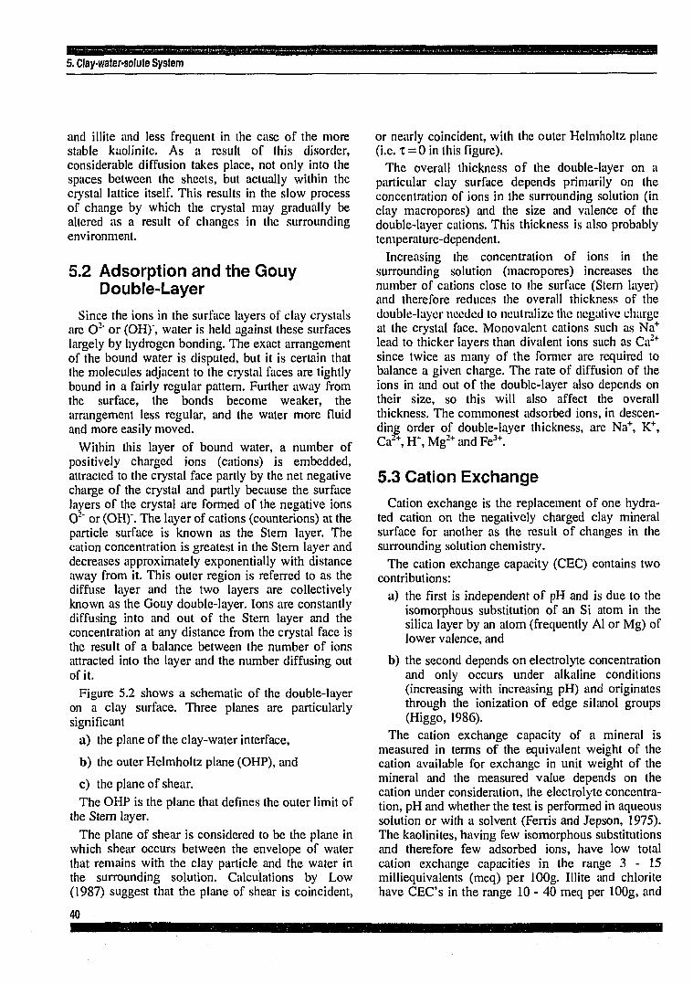
5. Clay-water-solute System
and illite and less frequent in the case of the more stable kaolinile. As a result of this disorder, considerable diffusion takes place, not only into the spaces between the sheets, but actually within the crystal lattice itself. This results in the slow process of change by which the crystal may gradually be altered as a result of changes in the surrounding environment.
5.2 Adsorption and the Gouy Double-Layer
Since the ions in the surface layers of clay crystals are O2" or (OH)", water is held against these surfaces largely by hydrogen bonding. The exact arrangement of the bound water is disputed, but it is certain that the molecules adjacent to the crystal faces are tightly bound in a fairly regular pattern. Further away from the surface, the bonds become weaker, the arrangement less regular, and the water more fluid and more easily moved.
Within this layer of bound water, a number of positively charged ions (cations) is embedded, attracted to the crystal face partly by the net negative charge of the crystal and partly because the surface layers of the crystal are formed of the negative ions O2" or (OH)". The layer of cations (counterions) at the particle surface is known as the Stern layer. The cation concentration is greatest in the Stern layer and decreases approximately exponentially with distance away from it. This outer region is referred to as the diffuse layer and the two layers are collectively known as the Gouy double-layer. Ions are constantly diffusing into and out of the Stem layer and the concentration at any distance from the crystal face is the result of a balance between the number of ions attracted into the layer and the number diffusing out of it.
Figure 5.2 shows a schematic of the double-layer on a clay surface. Three planes are particularly significant
a) the plane of the clay-water interface,
b) the outer Helmholtz plane (OHP), and
c) the plane of shear. The OHP is the plane that defines the outer limit of
the Stern layer. The plane of shear is considered to be the plane in
which shear occurs between the envelope of water that remains with the clay particle and the water in the surrounding solution. Calculations by Low (1987) suggest that the plane of shear is coincident,
or nearly coincident, with the outer Helmholtz plane (i.e. x = 0 in this figure).
The overall thickness of the double-layer on a particular clay surface depends primarily on the concentration of ions in the surrounding solution (in clay macropores) and the size and valence of the double-layer cations. This thickness is also probably temperature-dependent.
Increasing the concentration of ions in the surrounding solution (macropores) increases the number of cations close to the surface (Stern layer) and therefore reduces the overall thickness of the double-layer needed to neutralize the negative charge at the crystal face. Monovalent cations such as Na+
lead to thicker layers than divalent ions such as Ca2+
since twice as many of the former are required to balance a given charge. The rate of diffusion of the ions in and out of the double-layer also depends on their size, so this will also affect the overall thickness. The commonest adsorbed ions, in descending order of double-layer thickness, are Na+, K+, Ca2+,H+,Mg2+andFe3+.
5.3 Cation Exchange Cation exchange is the replacement of one hydra-
ted cation on the negatively charged clay mineral surface for another as the result of changes in the surrounding solution chemistry.
The cation exchange capacity (CEC) contains two contributions:
a) the first is independent of pH and is due to the isomorphous substitution of an Si atom in the silica layer by an atom (frequently Al or Mg) of lower valence, and
b) the second depends on electrolyte concentration and only occurs under alkaline conditions (increasing with increasing pH) and originates through the ionization of edge silanol groups (Higgo, 1986).
The cation exchange capacity of a mineral is measured in terms of the equivalent weight of the cation available for exchange in unit weight of the mineral and the measured value depends on the cation under consideration, the electrolyte concentration, pH and whether the test is performed in aqueous solution or with a solvent (Ferris and Jepson, 1975). The kaolinites, having few isomorphous substitutions and therefore few adsorbed ions, have low total cation exchange capacities in the range 3 - 1 5 milliequivalents (meq) per lOOg. Illite and chlorite have CEC's in the range 10 - 40 meq per lOOg, and
40

5. Clay-water-solute System
the smectites and vermiculite have very high CEC's, typically 80-150 meq per lOOg, since the interlayer cations are also available for exchange. Cation exchange capacities can be calculated from first principles for a given clay mineral (van Olphen, 1977).
5.4 Anion Exchange The anion exchange capacity of clays is mainly a
result of adsorption on positively charged particle-edge aluminium sites. It depends on electrolyte concentration and decreases with increasing pH. Thus exchange capacity for CI" of kaolinite becomes zero at around pH 7 (Eriksen and Jacobsson, 1981). In natural clays, at typical porewater pH, the anion exchange is generally very low (Higgo, 1986).
5.5 Double-Layer Theory Double-layer theory is treated in a number of texts
including Verwey and Overbeek (1948) and van Olphen (1977). Two problems are of particular interest, the potential and charge distributions for a single double-layer, associated with the surface of a single clay particle, and the equivalent distributions and resulting force between the interacting double-layers, associated with two clay particles held in close proximity. The single flat double-layer was analyzed by Gouy (1910) and Chapman (1913) using the Poisson-Boltzmann equation. In the Gouy--Chapman theory, ions were considered to be point charges which leads to impossibly high ion concentrations next to the clay surface. The theory has been corrected for this effect (Stern, 1924), and is summarized in van Olphen (1977) for both single and interacting flat double-layers.
Langmuir (1938) assumed that the repulsive pressure tending to force two clay particles apart is equal to the osmotic pressure at a point midway between their parallel surfaces less the osmotic pressure of the external "free solution". Based on this concept, the swelling pressure of a clay can be estimated using double-layer theory from basic chemical, mineralogical and physical properties of the clay-porewater system (see, for example, Mitchell, 1976; van Olphen, 1977; and Madsen and Muller-Vonmoos, 1985). Double-layer theory has also been used to estimate the compressibility of pure clays (Bolt, 1956).
The interpretation of swelling pressure in terms of small-scale osmosis is not without its critics. Low (1987) suggests that the apparent agreement between
experimental data and the double-layer model stems from:
a) the assumption that all the water in the clay resides within the double-layers, or
b) neglect of the Stern layer cations in the analysis. He presents strong evidence that the swelling
pressure tending to separate clay surfaces in pure clays is primarily a consequence of surface hydration and presents a semi-empirical relationship for the hydration pressure as a function of water content and surface area in smectites. Other investigators assume that swelling pressure is the sum of the osmosic and hydration components, with the long-range effects of the osmotic mechanism becoming relatively more important at larger interparticle separations (and water contents). It has also been suggested that it is the hydration of the cations, rather than the clay surface, that is responsible for the hydration force.
5.6 Significance of the interparticle Forces
From the above discussion, the total stress o (force per unit area) supported by a natural clay under in situ conditions may be divisible into four components:
a = o ; + R - A + u (5.1)
where a, is the interparticle stress associated with particle to particle contacts, R is the interparticle repulsive force per unit area between clay platelets produced by the osmotic and/or hydration mechanisms, A is the attractive force per unit area between clay platelets produced by van der Waals or electrical forces and u is the pore pressure. This relationship was discussed by Lambe (1960) in relation to the shear strength of clays.
In natural clays, at typical water contents, the magnitude of the repulsion component R of total stress considerably exceeds the magnitude of the attraction component A so that, in qualitative arguments at least, we can ignore the second component and assume A = 0. The actual value of R will depend on precisely the same parameters that determine the thickness of the Gouy double-layers (i.e. water content, specific surface, valence and size of adsorbed cations, CEC, concentration of ions in solution in the larger pores and temperature).
Assume that a clay formation is chemically perturbed by the introduction of fresh water into an exploratory borehole. As the clay imbibes water, the magnitude of the repulsive pressure R will increase
41
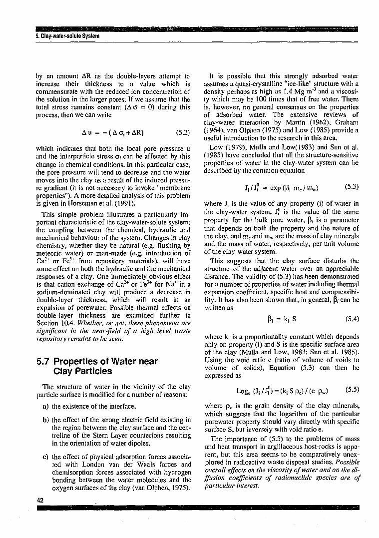
5. Clay-water-solute System
by an amount AR as the double-layers attempt to increase their thickness to a value which is commensurate with the reduced ion concentration of the solution in the larger pores. If we assume that the total stress remains constant (A o = 0) during this process, then we can write
Au = - ( A o , + AR) (5.2)
which indicates that both the local pore pressure u and the interparticle stress <j, can be affected by this change in chemical conditions. In this particular case, the pore pressure will tend to decrease and the water moves into the clay as a result of the induced pressure gradient (it is not necessary to invoke "membrane properties"). A more detailed analysis of this problem is given in Horseman et al. (1991).
This simple problem illustrates a particularly important characteristic of the clay-water-solute system; the coupling between the chemical, hydraulic and mechanical behaviour of the system. Changes in clay chemistry, whether they be natural (e.g. flushing by meteoric water) or man-made (e.g. introduction of Ca2+ or Fe3+ from repository materials), will have some effect on both the hydraulic and the mechanical responses of a clay. One immediately obvious effect is that cation exchange of Ca2+ or Fe3+ for Na+ in a sodium-dominated clay will produce a decrease in double-layer thickness, which will result in an expulsion of porewater. Possible thermal effects on double-layer thickness are examined further in Section 10.4. Whether, or not, these phenomena are significant in the near-field of a high level waste repository remains to be seen.
5.7 Properties of Water near Clay Particles
The structure of water in the vicinity of the clay particle surface is modified for a number of reasons:
a) the existence of the interface,
b) the effect of the strong electric field existing in the region between the clay surface and the centreline of the Stern Layer counterions resulting in the orientation of water dipoles,
c) the effect of physical adsorption forces associated with London van der Waals forces and chemisorption forces associated with hydrogen bonding between the water molecules and the oxygen surfaces of the clay (van Olphen, 1975).
It is possible that this strongly adsorbed water assumes a quasi-crystalline "ice-like" structure with a density perhaps as high as 1.4 Mg m"3 and a viscosity which may be 100 times that of free water. There is, however, no general consensus on the properties of adsorbed water. The extensive reviews of clay-water interaction by Martin (1962), Graham (1964), van Olphen (1975) and Low (1985) provide a useful introduction to the research in this area.
Low (1979), Mulla and Low(1983) and Sun et al. (1985) have concluded that all the structure-sensitive properties of water in the clay-water system can be described by the common equation
J,/J? = exp(P, m c / m j (5-3)
where J¡ is the value of any property (i) of water in the clay-water system, J? is the value of the same property for the bulk pore water, p\ is a parameter that depends on both the property and the nature of the clay, and mc and mw are the mass of clay minerals and the mass of water, respectively, per unit volume of the clay-water system.
This suggests that the clay surface disturbs the structure of the adjacent water over an appreciable distance. The validity of (5.3) has been demonstrated for a number of properties of water including thermal expansion coefficient, specific heat and compressibility. It has also been shown that, in general, p\- can be written as
P¡ = k, S (5.4)
where k¡ is a proportionality constant which depends only on property (i) and S is the specific surface area of the clay (Mulla and Low, 1983; Sun et al. 1985). Using the void ratio e (ratio of volume of voids to volume of solids), Equation (5.3) can then be expressed as
Logc(Ji/j[)) = (k iSp c) /(e pw) (5.5)
where pc is the grain density of the clay minerals, which suggests that the logarithm of the particular porewater property should vary directly with specific surface S, but inversely with void ratio e.
The importance of (5.5) to the problems of mass and heat transport in argillaceous host-rocks is apparent, but this area seems to be comparatively unexplored in radioactive waste disposal studies. Possible overall effects on the viscosity of water and on the diffusion coefficients of radionuclide species are of particular interest.
42

am 5. Clay-water-solute System
5.8 Membrane Effects and Anion Exclusion
An ideal osmotic membrane is a semipermeable barrier that allows transport of the solvent but not of the solutes. Solutes are rejected on the basis of size and/or electrical restrictions. Clays can act as membranes of varying degrees of ideality, an attribute which is due to electrical restrictions on anion movement within the adsorbed water. In compacted clays, the clay platelets are forced into
such close proximity that the double-layers strongly interact and the cation-dominated interparticle space repels anions attempting to migrate through it. In order to maintain electrical neutrality in the outer or "free solution", cations must remain with their counterions and their movement through the clay is also restricted (Fritz, 1986). This mechanism is the source of "membrane effects" in clays and of anion exclusion (ultrafiltration) which is an important radionuclide retention/retardation mechanism. The significance of membrane effects, chemico-osmosis and ultrafiltration are considered in later chapters.

6. Hydrogeology
HYDROGEOLOGY
45

6. Hydrogeology
The primary objective of hydrogeological studies, within the general framework of site assessment and radiological safety studies, may be simply stated as the provision of data on the spatial (and possibly temporal) variation of groundwater flow velocity in order to quantify the advection terms in the radionuclide transport equation (see Chapter 8).
Although direct measurement of groundwater flow velocities and directions is feasible (tracer studies, etc.) and is probably more accurate than indirect methods, it is not practical to characterize a regional hydrogeological system using direct methods of measurement. Thus, the universally accepted approach is to sample, by in situ testing, the spatial distribution of hydraulic potential (head) and hydraulic conductivity, to establish the geometry and boundary conditions of the problem (topography, geology, recharge, etc.), and to obtain the required How velocities and directions by solution of Laplace's equation (see p. o4, Freeze and Cherry, 1979) using a suitable numerical modelling code.
In high permeability environments (aquifers, etc.), it would appear that the accepted methodology yields satisfactory results, provided that the heterogeneity and anisotropy of flow are adequately represented. This suggests that sampling and measurement errors do not unduly affect the calculations. Furthermore, it suggests that our "conceptual model" of fluid flow in high permeability environments does not diverge significantly from reality. The four implicit assumptions of this conceptual model are
a) Darcy's law is valid and local groundwater flux is determined exclusively by the negative gradient of hydraulic potential,
b) the potential gradients arise because of elevation differences between the recharge and discharge areas,
c) the hydrological system is in steady-state (i.e. no temporal variations in hydraulic potential or flux), and
d) single phase flow is occurring (no gas phase). These assumptions are reasonable for groundwater
flow, at depth, in most high permeability rocks under natural conditions (not influenced by man), provided that recharge is moderately constant (when averaged over appropriate time-periods).
In low permeability environments, the situation becomes more complicated. First of all, the in situ measurements are more difficult to perform, requiring equipment with much better resolution than is acceptable in studies of high permeability rocks.
The flow transients during in situ testing are also likely lo be far more protracted, resulting in time-consuming testing procedures. The volume of rock sampled by a test will generally be smaller in low permeability rocks and, if the rock is fractured, flow may be occurring primarily in these discontinuities, leading to additional testing problems.
The overall effect of these testing difficulties in low permeability rocks is that the hydraulic potentials and hydraulic conductivities determined in the field will be subject to significant errors and uncertainties associated with:
(i) measurement,
(ii) data reduction, and (Hi) sampling.
The effort necessary to reduce these errors and uncertainties to an acceptable level may be quite considerable.
Having acquired the field data, the next task is to determine the groundwater flow velocities in the low permeability hydrogeological system. In the first instance, the high permeability "conceptual model", assuming Darcy's law and steady-state, might be adopted. If the measured hydraulic potentials can be reconciled with the predictions of the model, based on reasonably representative hydraulic properties, then the hydrogeological problem is more or less solved and radionuclide transport modelling can proceed using the calculated velocities.
Even in this case, the uncertainties are likely to be of sufficient magnitude to demand that the hydrogeological predictions be independently validated by geochemical studies of the groundwater chemistry (see Chapter 7).
Unfortunately, life is rarely this simple. It would appear to be a fairly common experience in radioactive waste disposal investigations that the measured hydraulic potentials cannot be reconciled with a simple "conceptual model". If uncertainties in the field data can be eliminated, which is not necessarily the case, then assumptions of the model require scrutiny.
In the oil industry, a pore fluid pressure which departs significantly from the calculated pressure at the base of a column of fluid to the surface (= hydrostatic pressure) is recognized as an "anomalous" or "abnormal" pressure. A better definition of anomalous pressure might be "a pressure which cannot be reconciled with gravity-driven, single-phase, Darcy flow occurring under isothermal and steady-state conditions".
47
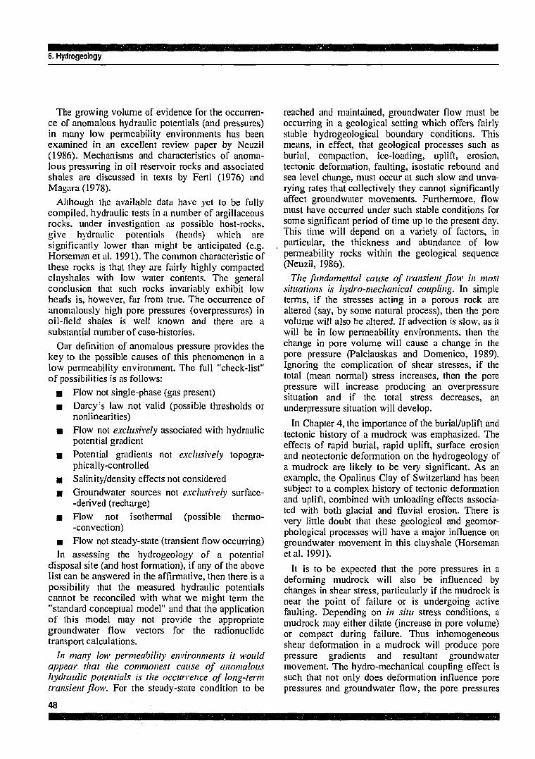
6. Hydrogeology
The growing volume of evidence for the occurrence of anomalous hydraulic potentials (and pressures) in many low permeability environments has been examined in an excellent review paper by Neuzil (1986). Mechanisms and characteristics of anomalous pressuring in oil reservoir rocks and associated shales are discussed in texts by Fertl (1976) and Magara(1978).
Although the available data have yet to be fully compiled, hydraulic tests in a number of argillaceous rocks, under investigation as possible host-rocks, give hydraulic potentials (heads) which are significantly lower than might be anticipated (e.g. Horseman et al. 1991). The common characteristic of these rocks is that they are fairly highly compacted clayshales with low water contents. The general conclusion that such rocks invariably exhibit low heads is, however, far from true. The occurrence of anomalously high pore pressures (overpressures) in oil-field shales is well known and there are a substantial number of case-histories.
Our definition of anomalous pressure provides the key to the possible causes of this phenomenon in a low permeability environment. The full "check-list" of possibilities is as follows:
• Flow not single-phase (gas present) • Darcy's law not valid (possible thresholds or
nonlinearities) • Flow not exclusively associated with hydraulic
potential gradient • Potential gradients not exclusively topogra
phically-controlled • Salinity/density effects not considered a Groundwater sources not exclusively surface-
-derived (recharge) • Flow not isothermal (possible thermo-
-convection) • Flow not steady-state (transient flow occurring) In assessing the hydrogeology of a potential
disposal site (and host formation), if any of the above list can be answered in the affirmative, then there is a possibility that the measured hydraulic potentials cannot be reconciled with what we might term the "standard conceptual model" and that the application of this model may not provide the appropriate groundwater flow vectors for the radionuclide transport calculations.
In many low permeability environments it would appear that the commonest cause of anomalous hydraulic potentials is the occurrence of long-term transient flow. For the steady-state condition to be
reached and maintained, groundwater flow must be occurring in a geological setting which offers fairly stable hydrogeological boundary conditions. This means, in effect, that geological processes such as burial, compaction, ice-loading, uplift, erosion, tectonic deformation, faulting, isostatic rebound and sea level change, must occur at such slow and unvarying rates that collectively they cannot significantly affect groundwater movements. Furthermore, flow must have occurred under such stable conditions for some significant period of time up to the present day. This lime will depend on a variety of factors, in particular, the thickness and abundance of low permeability rocks within the geological sequence (Neuzil, 1986).
The fundamental cause of transient flow in most situations is hydro-mechanical coupling. In simple terms, if the stresses acting in a porous rock are altered (say, by some natural process), then the pore volume will also be altered. If advection is slow, as it will be in low permeability environments, then the change in pore volume will cause a change in the pore pressure (Palciauskas and Domenico, 1989). Ignoring the complication of shear stresses, if the total (mean normal) stress increases, then the pore pressure will increase producing an overpressure situation and if the total stress decreases, an underpressure situation will develop.
In Chapter 4, the importance of the burial/uplift and tectonic history of a mudrock was emphasized. The effects of rapid burial, rapid uplift, surface erosion and neotectonic deformation on the hydrogeology of a mudrock are likely to be very significant. As an example, the Opalinus Clay of Switzerland has been subject to a complex history of tectonic deformation and uplift, combined with unloading effects associated with both glacial and fluvial erosion. There is very little doubt that these geological and geomor-phological processes will have a major influence on groundwater movement in this clayshale (Horseman etal. 1991).
It is to be expected that the pore pressures in a deforming mudrock will also be influenced by changes in shear stress, particularly if the mudrock is near the point of failure or is undergoing active faulting. Depending on in situ stress conditions, a mudrock may either dilate (increase in pore volume) or compact during failure. Thus inhomogeneous shear deformation in a mudrock will produce pore pressure gradients and resultant groundwater movement. The hydro-mechanical coupling effect is such that not only does deformation influence pore pressures and groundwater flow, the pore pressures
48

6. Hydrogeology
themselves also exercise a dominant control on deformation and failure. The effects of overpressu-ring on faulting are well known (Hubbert and Rubey, 1959).
In a simple geological environment, such as a gradually subsiding continental basin, with no evidence of recent uplift, major erosion episodes, ice-loading or neotectonic activity, the occurrence of long-term transient flow within the low permeability sequence of rocks may not be a matter of concern.
Even in this simple geological environment, the calculation of groundwater movement in a potential argillaceous host-rock may not be straightforward. The main premise of hydrogeological modelling is that Darcy's law is valid in all rock-types and the groundwater flux is exclusively related to the negative gradient of hydraulic potential. No other potentials are generally considered.
One basic requirement for the validity of Darcy's law is that the permeant should be non-reactive with the porous medium. As was indicated in the last chapter, the clay minerals of a mudrock generally exhibit exceedingly complex interactions with permeating solutions. Thus, only in the very special case of a permeant which is chemically identical (pH, Eh, ionic strength, major ions, etc.) with the mudrock porewater, does flow in a mudrock meet the basic requirement of being nonreactive.
Clay-water-solute interactions are at the heart of many of the anomalous hydrogeological responses of clays and mudrocks. A far from exhaustive list of processes, which are either known to affect flow in clays or have been inferred to do so from indirect evidence, are:
• Non-Darcy flow (thresholds and nonlinearities) B Sensitivity of hydraulic conductivity to water
chemistry • Chemico-osmosis and "membrane effects" a Thermo-osmosis • Swelling Non-Darcy flow may be defined as flow in a
porous medium in which the flux ceases to vary in proportion to the negative gradient of hydraulic potential. It takes the form of thresholds, below which the flux is zero, and of nonlinearities in the relationship between flux and gradient.
Based on our knowledge of the sensitivity of the thickness of the Gouy double-layers in clay to changes in solution chemistry, the dependence of hydraulic conductivity on the chemistry of the permeant is to be expected.
Chemico- and thermo-osmosis are particular examples of a range of related "coupled flow" phenomena in clays (see Section 6.4). In these particular mechanisms, the groundwater flux is associated with the gradients of chemical potential and temperature, respectively. The significance of thermo-osmosis in the near-field of a repository contain heat-emitting waste is examined further in Section 10.7.
It is not possible to make general statements on the importance, or otherwise, of the non-Darcy, non-hydraulic, groundwater flow mechanisms in clay-rich media (soils and rocks) and any such statements which appear in the literature should be viewed with the greatest of caution. Without a doubt, the key to this complex behaviour lies in the intricate responses of the double-layer (Stern layer and diffuse layer) at the clay mineral surface and associated interparticle forces to changes in the local physico-chemical environment of the medium. It therefore seems probable that mnhydraulic mechanisms become more important as the ratio of the mass of adsorbed water to the mass of free water increases. This suggests that the average interparticle spacing A. between clay platelets, a quantity which is easily estimated, might provide a good measure of the relative importance of these mechanisms in a given mudrock. We might anticipate that as X decreases, the relative contribution of the non-hydraulic flux to the total groundwater flux increases, depending, of course, on the magnitude of the potential gradients. Thus, although the groundwater flow velocities in more indurated and compact mudrocks (e.g. clayshales) are likely to be smaller than in less-indurated clays, the mechanisms of groundwater movement are likely to be more complex in the more compact rock.
Swelling was introduced in the last chapter, and is an important process in waste disposal studies since it has hydrogeological significance as- a potential fracture sealing mechanism, is an important consideration in repository engineering (Section 11.1.7) and is a major consideration in studies of buffer/backfill performance.
6.1 Is Mudrock Hydrogeology Important?
Given the probable complexity and uncertainty in modelling groundwater flow in argillaceous rocks, the question arises as to whether the hydrogeology of the mudrock host is actually important in assessing disposal options and in site characterization.
49

6, Hydrogeology
If the geological succession at a proposed site comprises mostly argillaceous rocks, of sufficient plasticity to preclude the occurrence of significant fracture flow, then a low flow environment for disposal is more or less assured. Since the importance of the diffusion mechanism in clays has often been emphasized, is it possible to ignore advection in radionuclide transport studies of these media?
In an appropriately selected mudrock, the hydraulic conductivity will generally be less than 10*y m.s"1 and it may be as low as 10"12 m.s"1. Assuming a value of 10'10 m.s'1 and a mudrock porosity of 0.4 then, under a typical hydraulic gradient of 1%, the average time for a water molecule to move down gradient for a distance of 100 m in the mudrock is 1.3 x 10⁵ years. Ignoring dispersion effects, this is equivalent to the average time for a non-sorbing radionuclide to be transported the 100 m by advection.
A reasonable estimate of the distance travelled by a radionuclide by diffusion in time t can be obtained by calculating the root-mean-square distance Xn,i„ given by
Xnns = ( t -D a p p ) a 5 (6.1)
If the diffusing species is released at a plane surface, 68% of it will be found within the distance Xm,s from the surface (Higgo, 1986).
The apparent diffusion coefficient Dapp of a non-sorbed species in clay is of the order of 2 x 10"10
m2.s"'. Taking Xms as 100 m, then the time taken for the radionuclide to traverse this distance by diffusion alone is 1.6 x 10⁵ years.
Thus the transit times for the advection and diffusion mechanisms are not dissimilar if typical mudrock/nuclide properties are assumed. Although the actual flux of radionuclide.'! has not been considered in this simple analysis, the calculation suggests that the advection mechanism cannot be ignored. Furthermore, if the mudrock is heterogeneous (joints, fissures, sandy/silty layers, etc.), then the localization of groundwater flow within these discrete features of the host-rock could become a matter of considerable importance.
Safety studies may require consideration of radionuclide migration in the event of failure (say, by faulting) of the mudrock barrier. This will demand a detailed knowledge of the regional hydrogeology, including the role of the low permeability units. It is therefore concluded that, despite the difficulties and uncertainties, the hydrogeology of mudrocks remains an important issue.
6.2 Basic Hydrogeological Parameters
There are a number of difficulties in applying standard hydrogeological concepts and parameter definitions to mudrocks. This section provides a brief review of some of the main points.
6.2.1 Potentials, Heads and Pore Pressures
Hubbert (1940) defines potential as "a physical quantity, capable of measurement, whose properties are such that flow occurs from regions in which the quantity has higher values to those in which it has lower, regardless of the direction in space".
For ad'/ective flow in a porous medium, the quantity which satisfies this definition is the mechanical energy per unit mass of water referred to an arbitrary reference state. If we take z to be a vertical coordinate with the positive direction upwards and take as our reference state water at elevation z = 0, at rest, and at pressure uo, then the work done per unit mass in raising the water isothermally to elevation z and pressure u, and accelerating it to velocity v is
0 = g z + (v2/2) + f du/pw(u) (6.2)
where p„. is the density of water. Since the water velocity is usually extremely small in a porous medium, the second term in (6.2) is normally dropped. If the water is assumed to be incompressible, then this simplifies to
O = g z + (u - Uo) / pw (6.3)
or
<!> = <&.+ (fy (6.4)
where 0 : is the elevation (gravitational) potential and <&,, is the pressure (matrix) potential. Since the acceleration due to gravity g varies little from place to place over the surface of the earth, we can divide (6.3) by g and still meet Hubbert's requirement for a potential. Using gauge pressures (u0 = atmospheric = 0) we obtain
<D/g = z + (u-Uo)/(g p j (6.5)
or
h = z + hp (6.6)
where h is the total head, z is the elevation head and hp is the pressure head. Chemico-osmotic flow is
50

6. Hydrogeology
widely recognized in clays and an additional potential is often included in the definition of total potential (Bolt and Miller, 1958; Yong and Warkentin, 1975), thus
O = ct. + cfy + d), (6.7)
where Ot, ¡s often termed the solute potential, defined as the work done per unit mass of water in transporting reversibly and isothermally an infinitesimal quantity of water from a pool of pure water, at a specified elevation and at atmospheric pressure, to a pool containing a solution identical in composition to the pore water, at the same elevation and pressure as the reference pool. The significance of the solute potential to hydraulic testing in clayshales has been examined in Horseman et al. (1991).
6.2.2 Total and Effective (Flowing) Porosity
The common measure of the free fluid content of a porous medium is the total porosity nt which is defined as the ratio of the total pore volume Vp to the bulk volume Vi, of the rock.
n, = Vp / V„ (6.8)
The effective porosity nc is the fractional volume of the interconnected or accessible pores
ne = V a / V b (6.9)
where Va is the volume of pores accessible to advective flow. The effective porosity is also known as the "kinetic porosity" (de Marsily, 1986) or the "flowing porosity".
In compacted mudrocks we encounter difficulties in both, the definition and the measurement of total porosity and these difficulties become even more acute when we attempt to distinguish effective porosity. Our problems stem from the microscopic scale of the voids in compacted clay and the complex clay-water interactions near the clay mineral surfaces. We can distinguish four types of water in clays:
a) interlayer water within the sheet structure of certain clay mineral (e.g. smectites),
b) orientated water molecules and cation-hydration water strongly adsorbed at the surface of clay minerals (Stern layer),
c) loosely adsorbed water in the diffuse layer associated with clay minerals, but more remote from the surfaces, and
d) free water which is sufficient remote from the clay particles to be unaffected by them,
The definition of the total porosity of a saturated mudrock is therefore somewhat arbitrary, but the writer prefers to base n, on the water extractable in a standard moisture content test (at 105°C), in which case
Total porosity^ Macroporosity + Microporosity
(6.10)
where most, if not all, of the micropore water is adsorbed to clay minerals. The total porosity determined by water content measurements may differ from that determined by high pressure mercury injection experiments.
It is generally agreed that most of the pore space in clays is actually interconnected, but that significant groundwater flow only occurs in a fraction of this total space. Groundwater flow in clay will occur along the paths of least resistance and, given the magnitude of the forces of claywater interaction, these paths probably comprise networks of larger pores (macropores).
Pore size distribution is evidently of great importance in assessing the hydrogeological properties of mudrocks. Table 6.1 shows pore size distributions for a range of British mudrocks obtained by high pressure mercury injection experiments (Taylor and Smith, 1985). The results are presented in terms of the pore diameters (nm) which correspond with fixed percentages (20, 50 and 80%) of the total porosity. For example, 50% of the total pore space in London Clay from Warden Bay consists of pores which are less than 62.3 nm in diameter. The skewness and sorting index are also quoted. It should be noted that these samples were probably taken from shallow depths.
In relation to trje Boom Clay, which ha.s a water content of around 20 wt-% and a specific surface of around 100 m2.g"', Henrion and Fonteyn (1984) conclude that almost all the water is adsorbed and resides in the double-layers and there is little room left for larger pores and for what might be called a bulk or interstitial solution (free water).
Figure 6.1 shows the effect of compaction on pore size distribution in the Poseidon Shale of the Lower Saxony Basin of Germany. These results were obtained by mercury injection using pressures up to 345 MPa. This technique gives the pore throat size and in data reduction it was assumed that the pore radii were one order of magnitude greater than the pore throat radii. In examining these results, it should
51

maaaaammam 6, Hydrogeology
Table 6.1 Pore-size distributions by mercury injection (as percentage of total porosity). Test by C.H. Crtuay of
Durham University. Reproduced from Taylor and Smith (1985).
' • * - * * I
1. London Clay (Warden Bay, Isle of Sheppey
2, London Clay (City of London)
3. Fuller's earth (Wobum, Bedfordshire)
4, Oxford Clay (Oxford City)
5. Lias Clay (Near Minehead, Somerset)
6. Coal Measures mudstone (Nun Monkton, N. Yorkshire)
Diameters less than (nm)
d20
18.0
18.4
9.9
18.6
10.4
10.8
dso
62.2
61.2
27.6
82.0
19.2
19.8
dso
206.0
185.2
1136.0
312.0
50.0
60.0
Skweness (i)
0.96
0.91
14.60
0.86
1.41
1.65
Sorting Index (2)
3.4
3.2
10.7
4.1
2.2
2.4
(l) Skewness = (d,so.d2o)l(d5o)2
(2) Sorting index = tfdxold2o)
be borne in mind that the thickness of a single layer of adsorbed water molecules is approximately 0.3 nm (Duppenbecker et al. 1991). Given the predominance of aligned clay minerals in a shale, the smaller pore radii may, in reality, be roughly equal to the throat radii.
6.2.3 Permeability and Hydraulic Conductivity
The intrinsic permeability k (m2) is a property of the geological medium and is not affected by the nature and properties of the fluid. Darcy's law can be expressed in one-dimensional form, in terms of the intrinsic permeability, by
v = k p g /u . ( -dh/dL) (6.11)
where v is the Darcy velocity or the rate of transmission of the liquid through the medium (m.s'2), p is the density of the liquid (kg.m"3), g is the acceleration due to gravity (9.81 m.s"2), u. is the dynamic viscosity of the liquid (Pa.s) and -dh is the loss of head over distance dL.
The darcy is an alternative unit of intrinsic permeability which is favoured by the oil industry.' One darcy is equivalent to 9.87 x 10"13 m2.
If the permeant is water, then the hydraulic conductivity K (m.s*1) becomes an appropriate measure of
52
the capacity of the medium to transmit the permeant. The hydraulic conductivity and the intrinsic permeability are related by
K = k pw g / ii (6.12)
The dynamic viscosity of water depends on temperature and, to a lesser extent on pressure and salinity. Values for pure water at temperatures in the range 0° -100°C and atmospheric pressure are tabulated in de Marsily (1986). At 15.5°C and atmospheric pressure, the dynamic viscosity of pure water is 1.002 x 10"3
Pa.s. Taking this value and assuming the density of water to be 1000 kg m"3, the hydraulic conductivity K (m.s"1) may be determined by multiplying the intrinsic permeability k (m2) by 9.80 x 106. Other useful conversion factors for permeability units are given in Freeze and Cherry (1979).
Table 6.2 shows typical ranges for the hydraulic properties of British mudrocks, including the Tertiary London Clay, the Cretaceous Gault Clay, and the Upper Jurassic Oxford Clay. Values for post-palaeozoic rocks are given for depths of up to 20m below ground level (Tellam and Lloyd, 1981). The more plastic clays in this list exhibit laboratory-determined hydraulic conductivities in the range 10"8 to 10'12 m.s"1
and field values in the range 10"7 to 10"12 m.s'1
The hydraulic conductivity of clay is affected by fabric, grain size and shape, grain size distribution,

6. Hydrogeology
temperature, and by effective stress (Tellam and Lloyd, 1981). The effect of grain size and shape on the hydraulic conductivity of different clay types has been investigated by Mesri and Olsen (1971) who report that the presence of pedal structure is associated with higher hydraulic conductivity values. The presence of various amounts of non-clay grade material will increase hydraulic conductivity (Rieke
and Chillingarian, 1974). For clay compacted minerals compared at the same water content, the hydraulic conductivities are in the order monlmori-llonite < attapulgite < illile < kaolinile (Mitchell, 1976).
Young et al. (1964) describe an unexplained increase in intrinsic permeability with temperature.
100
75
Fraction of pore volume en
(%)
25
0 &t 1
Least compacted
Most compacted
10 Pore radius equivalents (nm)
100
100- 100-
10 50 100
Pore radius ranges (nm)
75-
(%) 50 -
25-
0
BBB8 JL 10
I 50 100
Pore radius ranges (nm)
.^*?J?~!^¿X™S*Kí7!í^
p sssmaaesaisassaasit
Figure 6.1 Pore radius distribution in four samples of Poseidon Shale from the Lower Saxony Basin of Germany,
showing the effect of increasing levels of compaction (after Duppenbecker et al. 1991).
53

HBMil 6. Hydrogeology
Table 6.2 Typical ranges for hydraulic properties of British mudrocks (values for postpalaeozoic rocks
are given for depths of up to 20 m below ground level). Modified from Tellam and Lloyd (1981).
(1) Hydraulic conductivity determined in vertical direction (2) Hydraulic conductivity determined predominantly in horizontal direction (3) Unweathered
Formation
Recent
Pleistocene
London Clay
Gault clay
Oxford Clay
Merch Mudstone Group
Coal Measures (3)
Other Palaeozoic Rocks (3)
Laboratory hydraulic
conductivity (1) ( ras 1 )
10"8-10-10
10"8-10"11
10-10-10"12
10-10-10-12
io-11-io-12
10"9-10"11
io-10-io-12
<1(T11
Field hydraulic
conductivity (2) (m.s-1)
10"7-10-10
10'6-10"11
10'8 -10'1 2
10"7-10"9
io-9-io-11
10'6-10"9
10"5-10'11
10"5-10"11
Total porosity
(%)
40-80
30-50
30-50
30-50
30-50
20-40
1-10
< 1-10
Laboratory specific storaae
( m l 10"3
io-3
io-3
10"4
10"3-10'4
io-4
—
—
The interaction of clays with permeating pore water can give rise to increases or decreases in hydraulic conductivity due to chemical effects on the extent of clay dispersion and on swelling (Quirk and Schofield, 1955; Frenkel et al. 1978). Compaction and the associated decreases in porosity of a clay results in a decrease in hydraulic conductivity (Olsen, 1972).
6.2.4 Predicting Intrinsic Permeability
A number of empirical and semi-empirical relationships have been developed to predict the permeability of granular soils and other porous media.
An equation reflecting the influence of the permeant and the soil characteristics on permeability was developed by Taylor (1948), by considering flow through a porous medium to be similar to flow in a bundle of capillary tubes and by applying Poiseuille's law. The intrinsic permeability is given by
u (1-e)2
Q(6.13)
where d is some effective particle diameter, p and u. are the density and dynamic viscosity of the liquid, C is a shape factor and e is void ratio.
The intrinsic permeability k (m2) of granular soils can also be estimated by the Kozeny-Carman equation
Pg K0 T" S" \L (1 -n)~
(6.14)
where K0 is the pore shape factor (= 2.5), T is the tortuosity factor (= V2), S is the surface area of particles per unit volume of the medium and n is the porosity, (no distinction is made between total and effective porosity).
This relationship provides a good prediction of the intrinsic permeability of coarse-grained granular materials (e.g. silts and sands), but its application to clays is generally less satisfactory (Olsen, 1962). This is variously attributed to deviations in Darcy's law, electrokinetic effects, high viscosity of the pore fluid, the highly tortuous nature of the flow paths and the very wide spread of pore sizes in clays.
54

m 6, Hydrogeology
6.3 Non-Darcy Flow
Departure from Darcy's law in clays may take the form of nonlinearity between the water flux and the gradient of hydraulic potential or a threshold hydraulic gradient may exist, which must be exceeded if flow is to occur.
Laboratory evidence for non-Darcy flow through clays has been widely reported. Deviations from Darcy's law in pure and natural clays up to gradients of 900 were measured by Lutz and Kemper, 1959. Experiments by Miller and Low (1963) led to the conclusion that there was a threshold gradient for flow in sodium montmorillonite. Apparent deviations from Darcy's law for flow in an undisturbed soft clay are also reported in Hansbo (1960; 1973).
Possible explanations of the behaviour are the non-Newtonian behaviour of adsorbed water, electrochemical viscous drag the occurrence of coupled flow (see below), hydrodynamic particle movement and clogging, and interactions with the permeant such as swelling.
A number of suggestions have been made for alternatives to Darcy's law to describe the relationship between flow velocity and gradient (Hansbo, 1960; Swartzendruber, 1962a; 1962b; 1963). The implications of nonlinearity and threshold gradients in relation to seepage and consolidation have been examined by Florin (19S1); Roza and Kotov (1958); Hansbo (1960); Bardon and Berry (1965); Mitchell and Younger (1967) and Schmidt and Westmann (1967).
Since laboratory-determined threshold gradients are often much higher than any naturally occurring hydraulic gradients, this raises the interesting possibility that the advective flux may be zero in some clays. However, further laboratory investigations have failed to confirm the existence of threshold gradients (Olsen, 1965; 1969; Gray and Mitchell, 1967; Mitchell and Younger, 1967, Miller et al. 1969; Chan and Kenney; 1973) and Darcy's law was obeyed exactly in the studies of Olsen (1965; 1969), Gray and Mitchell (1967) and Chan and Kenney (1973).
The results of these more recent and more carefully-controlled experiments have led a number of researchers to conclude that, all other factors held constant, Darcy's law is valid for clays. However, since most laboratory experiments have been performed on samples that are far less compacted than most naturally-occurring argillaceous rocks, the possibility of non-Darcy flow in the more indurated
rock-types cannot he excluded. Intuitively, a number of the proposed mechanisms for non-Darcy flow would become more important as pore sizes decrease due to compaction.
It is certain that particle migration leading to void plugging and unplugging, electrokinetic effects and chemical concentration effects can cause apparent deviations from Darcy's law. Internal swelling and dispersion of clay particles during permeation can also be responsible for changes in now rate and apparent non-Darcy behaviour (Hardcastle and Mitchell, 1974). Unless these effects can be shown to be of little importance, laboratory measurements should be mode under conditions as closely approximating to those in the field as possible (Mitchell, 1976).
6.4 Coupled Flow Phenomena
There is experimental evidence which suggests that the force driving groundwater movement in clays is not exclusively that associated with hydraulic gradient (Olsen, 1969; 1972; Fritz and Marine, 1983). Special characteristics of water-saturated clays give rise to "coupled flow" phenomena, whereby pore water movement is driven by non-conjugate forces. A non-conjugate force is one which is not normally associated with the flux.
There are many examples in nature of coupling in the flow of fluids, solutes, heat and electrical current and such phenomena are not exclusive to clays. The term "Onsagerian coupling" is often applied to these transport phenomena to distinguish the concept from mathematical coupling (Carnahan, 1987).
Coupled flow phenomena which result in groundwater movement are given the general name "osmosis". As already noted, in chemico-osmosis, the groundwater is driven by a force associated with the gradient of chemical potential, or loosely, by the solute concentration gradient. Similarly, in thermo-osmosis and electro-osmosis, it is a gradient of temperature and electrical potential which drives the water fluxes.
For chemico-osmosis to be possible, the medium must act as a semi-permeable membrane which allows water to pass but restricts the passage of solutes. As was noted in Chapter 5, anion exclusion is thought to be the main source of the membrane effect in clays (Fritz, 1986). Since some solutes do move in clays by diffusion or advective transport, the clay membrane will in most cases be non-ideal.
55

6. Hydrogeology
Although there is a reasonably large volume of' evidence to support the existence, and to define the general character of osmosis in clays, it is largely based on laboratory experiments on relatively pure, artificially-compacted clays. Only electro-osmosis has been indisputably demonstrated to occur at the large scale in natural clay formations. It is worth noting, however, that no large scale field experiments have yet been reported which are capable of identifying chemico- or thermoosmotic effects or of distinguishing them from other effects in clays. There is a clear requirement for such experiments to be undertaken.
Most work, to date, on the significance of the Onsager coupled processes to radioactive waste disposal has concentrated on mass transport in the near-field, where large thermal gradients in a compacted bentonite backfill or a clay host-rock may produce pore water movements by fhermoosmosis and the movement of solutes by thermo-diffusion (Soret effect). The importance of these and other thermal effects to performance assessment has been examined by de Marsily et al. (1987). This is examined further in Chapter 10.
A theory of one-dimensional transient flow in a non-ideal clay membrane under combined hydraulic and chemical gradients has been presented by Greenberg (1971) and Mitchell et al. (1973). Numerical simulations of coupled transport processes, including thermo- and chemicoosmosis, in saturated clays have been reported by Carnahan (1985; 1989). Fargue et al. (1989) provide a detailed theoretical review of coupled transport mechanisms in repository host-rocks and backfills, and provide a short section on these "non-dominant" transport mechanisms in clays.
The large literature on the occurrence and possible effects of chemico-osmosis in sedimentary basins which has been examined by Alexander (1990). Where a chemical concentration difference exists across a clay stratum behaving as a semi-permeable membrane, then an osmotic pressure difference will be established across the membrane which will drive a flux of water from the region of lower concentration to the region of higher. Measurements of hydraulic heads made in such a hydrogeological regime may appear to be anomalous (Jones, 1968; Horseman et al. 1991)
Where the concentration difference across the membrane is substantial, the resultant osmotic force is capable of generating fluid pressures which approach the magnitude of the total (lithostatic) stress (Haydon and Graf, 1986).
When an electrolyte solution is forced through a clay membrane, the effluent may be less concentrated than the original solution. This may happen in nature when the head differential due to regional topography is greater than, but acts in the opposite direction to, the osmotic pressure differential across the membrane. The effect, which has been termed "reverse osmosis", "ultrafiltration", "salt filtering" or "hyperfiltration", increases with increasing cation exchange capacity, decreasing porosity and decreasing input solution concentration (Hanshaw and Copien, 1973). Ultrafiltration may be important in the formation of saline groundwaters, geothermal brines and fluids of anomalous composition (Graf, 1982), and has been investigated as a mechanism for the precipitation of calcite cements (Fritz and Eady, 1985). The radionuclide retention mechanism of ion filtration would appear to be another example of this same process in action.
The possible role of osmosis in groundwater flow in the mixed sedimentary formations beneath Harwell Laboratory in Oxfordshire has been examined by Brightman et al. (1987).
6.5 Transient Flow Calculations suggest that transient flow may be
occurring in many low permeability geological environments (Neuzil, 1986). A particularly important mechanism is the stripping of overburden by erosion which can lead to low pressure transients (Toth and Miller, 1983). The removal of ice-loading can produce an almost identical effect.
One explanation of overpressuring in oil field shales is the compaction disequilibrium theory which suggests that the rate of sedimentation of the overburden on these rocks was so high that the excess pore pressures were unable to dissipate (Bre-dehoeft and Hanshaw, 1968). This of course suggests that the groundwater regime is one of transient flow. In certain geological settings, there seems little doubt that tectonic deformation can have similar effects (Berry, 1973). In the socalled "aquathermal effect", temperature changes are seen as a source of over-pressuring and resulting transient flow (Barker, 1972). Clay mineral transformation and cementation have also been invoked as a possible cause of overpressuring (Powers, 1967; Burst, 1969).
Bringing all these observations together, the conclusion must be drawn that there is a strong possibility that transient flow is occurring in many argillaceous and mixed sedimentary formations. If we also acknowledge osmotically-induced flow to be a
56

Bgrngggam
significant component of the total flow, then we must view these long-term transients as a response to hydraulic and chemical disequilihria in the geological system (Horseman et al. 1991).
6.6 Effect of Layering on Regional Flow
In any sequence of mixed high and low-permeability strata, groundwater will tend to flow along the more permeable layers and across the intervening less permeable layers. In sedimentar}' basins this results in sub-horizontal flow in the high-permeability rocks (through-flow) and sub-vertical flow across intervening mudrocks (cross-flow). Geological heterogeneity has a profound effect on the development of regional groundwater circulation patterns. The layering imparts a gross permeability anisotropy on the whole system, so that flow becomes elongated horizontally and does not penetrate to as great a depth as might be expected (Alexander etal. 1987).
In layered media, the groundwater flow direction may not coincide with the direction of the hydraulic head gradient, since flow has a tendency to follow the direction of highest permeability (de Marsily, 1986).
6.7 Role of Faults in Regional Flow
The general importance of faults and other discontinuities to groundwater flow in argillaceous rocks was stressed in Section 4.4. Our current understanding of the role of faulting in groundwater flow systems in general is very limited, and given the importance of this matter to safety assessment, it represents a priority area for field investigation and research.
The fluid flow properties of faults in sedimentary rocks are an important area of interest to the oil industry in relation to the performance of structures traps and the problem of trie secondary migration of hydrocarbons and a few guidelines are available from studies undertaken in these areas. Chapman (1987) concludes that there is no true general statement of the form "faults do/do not act as conduits for fluid flow". Such statements must be qualified to take into account the nature and strength of the faulted rock. With specific reference to the Tertiary mudstones, he notes that it is most unlikely that open faults can exist in these rocks below depths of 1 km because the strength of the mudstones is too small. Furthermore,
6. Hydrogeology
he reasons that for faults in which movement has been very slow, such as growth faults, it is hard to conceive of open fractures resulting in such materials under these conditions. There are several reservoirs in which the data strongly suggest that faults not only are sealing (otherwise there would be no petroleum field) but that they have always been (see, for example, Chapman, 1983).
6.8 Hydraulic Testing The difficulties associated with in situ hydraulic
testing in mudrocks and the lack, in the past, of incentives to examine these rock-types in detail have combined to deter much development in this area. Head measurements in mudrocks are not common practice. Where in situ testing has been performed, the testing systems employed have been either
a) standard oil- or water-well single or straddle packer systems operated in open-hole or perforated casing,
b) permanent hydrogeological completions using sand or gravel packs, or
c) soil mechanics completions using piezometers. In very stable boreholes, single or straddle packer
systems can be used to isolate specific sections of interest. These sections are usually cleaned before testing or are drilled with fresh water to minimise wall effects such as smearing. Short duration constant head or pulse tests are used to determine the permeability of the rock. Positive and negative pressures, related to some assumed head, are applied to the test zone. The "true" head is obtained by analysis of the recovery trend. Similar techniques have been applied in cased boreholes by explosively perforating the casing in the zones of interest and running a suaddle packer inside the casing (Brightman et al. 1987).
In low permeability clay and shale formations, the extended duration of the flow transients during testing and potential borehole stability problems may prompt the use of permanent hydrogeological completions. Robins et al. (1981) describe a number of gravel pack completions in deep boreholes drilled in a mixed sedimentary sequence at Harwell Laboratory in Oxfordshire. A cavity to accommodate the gravel pack was developed beneath the final casing in each hole by under-reaming. The final completion string, incorporating the gravel pack and well-screen, was lowered into each hole on drill pipe. The packer was inflated inside the casing and 20/40 mesh round gravel was pumped into the annulus around the
57

6. Hydrogeology
screen. A second packer, with a plastic pipe extending to surface, was installed in the casing to establish a test zone. Additional details and test results are given in Alexander and Holmes (1983).
For shallow depths, soil mechanics methods and hardware are applicable (see Hanna, 1973). Piezometer types are distinguished primarily by their "response times" which are a function of quantity of water that must move in from the formation to enable them to operate. The standpipe piezometer consists of a tube with a porous filter element on the end that can be sealed into the ground at the appropriate level. Two types of filter element are generally used, high air entry and low air entry. The Casagrande-type device is the most frequently installed standpipe piezometer. It has a cylindrical (low air entry) porous element protected by a perforated rigid sheath. The response time of this type of piezometer is comparatively slow. Water level in the open standpipe is measured with a dipmeter. In the closed-hydraulic piezometer the groundwater pressure is detected in a small piezometer tip and conducted through narrow-bore plastic tubes to a remote point, where the pressure is measured using a mercury manometer, Bourdon gauge or pressure transducer. These tubes must be regularly de-aired to avoid erroneous results. The closed-hydraulic piezometer has a shorter response time than open-tube systems. Electrical piezometers have a pressure transducer located close to the porous element and, because of their low system compliance, very rapid response is possible with these devices.
Piezometer tips are located in sand packs or filters with a particle size distribution designed to prevent the inward movement of fines from the formation. Bentonite is most often used to provide a seal above the pack, and if the piezometer is not near the base of the borehole, a bentonite seal is also placed beneath the sand pack. The length of the seal is typically 0.5 -1.5 m. The seals may be emplaced in the form of hand-moulded balls made from bentonite powder and water. Alternatively bentonite pellets may be used provided sufficient time is allowed for the pellets to swell before backfilling the hole. Multiple piezometers may be installed in a single hole provided that
care is taken to achieve proper sealing. The remaining sections of the borehole are filled with a bentonite/cement grout with a permeability the same as, or less than, that of the formation.
The Westbay multiple completion system was developed in Canada about 10 years ago to provide a high quality monitoring system. This form of permanent completion was used by NIREX in the Bradwell and Fullbeck shallow site investigations (Corke and Smith, 1991). Westbay packers are suitable for use in boreholes of 75 mm up to a finished hole diameter of 150 mm.
Bronders (1989) describes a technique being developed by SCK/CEN in Belgium for determining the macropermeability of Boom Clay. A 25m deep borehole, 0.15m in diameter, will be drilled from an underground location within the experimental gallery of the Project Hades URL. A 15m long sintered stainless steel (inox) filter will be installed in the test zone at the bottom of the hole and the upper part will be cased-off. The test zone will be sealed using an inflatable packer inside the casing. Two 26m deep monitoring boreholes will be drilled at distances of 0.5m and lm from the first hole, and each will be equipped with piezometers. The test zone will be subject to a complex pressure history and interpretation will follow the general scheme of Bredehoeft and Papadopulos (1980).
The implications of "borehole effects" including swelling and closely-related chemico-osmotic flow on hydraulic tests in clayshales have been examined by Horseman et al. (1991). Oil industry research on fluid/rock interaction around the wellbore is also examined in Section 11.4. The overall conclusions are that these effects can have very profound consequences when we attempt to measure hydraulic heads. The use of fresh-water as a test fluid is highly inappropriate in shales and there is a pressing need for research into more suitable testing techniques. One possibility is the use of non-polar, non-reactive test fluids. As an alternative, the chemistry of the test fluid might be regarded as a variable in characterizing these rocks enabling the chemico-osmotic flow phenomenon to be studied.
58

7. Geochemistry
GEOCHEMISTRY
59 fe

7. Geochemistry
Given the difficulties associated with the hydrogeo-logical characterization of low permeability argillaceous rocks, considerable emphasis should be placed on geochemical methods of investigation.
In a mudrock environment, it is possible that geochemical data will provide far more convincing evidence of the performance of the geological barrier than is obtainable by hydraulic testing and groundwater flow modelling. Furthermore, the migration of radionuclides within the mudrock barrier may be viewed as being primarily a geochemical, rather than a hydrogeological, problem.
Alexander et al. (1987) describe a good example of an early-stage, integrated study of the hydrochemical, hydrogeological and mineralogical characteristics of a shallow mudrock environment in the Middle Thames Valley area of southern England. This serves as a model of the type of study that could be undertaken at this stage of regional/site assessment.
The acquisition of data on the chemistry of groundwaters and mineral phases, together with the penological and mineralogical characteristics of the principal lithologies, is fundamental in site assessment. The applications of these data are numerous. Ideally, all boreholes should be fully-cored, so that systematic sampling and analysis will allow "property profiles" to be established for each borehole.
7.1 Hydrochemistry Detailed knowledge of groundwater chemistry, and
its spatial variation, will provide very valuable information on the hydrogeology of a site, water-rock interactions within the host formation, and some key aspects of repository performance:
• Origin, age and residence time of groundwater • Identification of groundwater systems • Salinity/density properties of groundwater • Chemistry of the clay-water-solute system • Chemical potentials for groundwater move
ment (coupled flow) • Radionuclide solubility, speciation and mobility • Corrosion and degradation of repository
materials The chemical composition and isotope properties
of the groundwater are indicative of the palaeo-hydrogeology of the site, enabling different groundwater systems to be identified, the origin and age of the groundwater to be established and residence times to be estimated. This information will not only assist in the development of a hydrogeologic
model, it will eventually provide the only method of independently validating the radionuclide transport calculations.
The wide applications of hydrochemical data in general site characterization are described by Andrews et al. (1988) and Gautschi and Scholtis (1989).
The coupling of the chemical, hydraulic and mechanical responses of mudrocks discussed in Chapter 5, emphasizes the requirement for an in-depth and integrated study of these effects within the low permeability units. It is important to recognize that the hydraclieinistry of a mudrock is, in part, determined by clay-water-solute interactions and that may not be possible to examine these areas in isolation.
If, as seems probable, the groundwater flux in mudrocks is partly driven by the chemical potential gradients (chemico-osmotic flow), then it would be important to evaluate the spatial variation of chemical potential. This would represent a significant departure from all existing site characterization methodologies and it may be a little premature to recommend such a novel approach at this stage. Since the required parameter, the chemical activity of the porewater, can be determined fairly easily determined by measurements of the adsorption isotherm on undisturbed mudrock cores (Chenevert, 1970), and by the chemical analysis of samples obtained from more permeable rocks, it might be worth contemplating a pilot-study of these chemicai potentials.
The solubility, speciation and mobility of radionuclides are strongly dependent on groundwater chemistry. This is examined in some detail in Chapter 8.
The corrosion and degradation rates of metal, concrete and other materials used within the repository will also be strongly dependent on the groundwater chemistry and these materials must be selected to be compatible with their chemical environment. Sulphate content is an important consideration in assessing the behaviour of concrete structures (repository linings, seals, etc.).
7.1.1 Hydrochemical Programme
The key factor to be borne in mind in establishing a hydrochemical programme is that the degree sophistication of the chemical analyses must be matched to the quality of the available groundwater samples and to the general level of understanding of the site geology. There is absolutely no point in attempting
61

7. Geochemistry
sophisticated analyses on poor quality, contaminated samples.
Three programme phases may be defined:
• Data compilation and routine analysis • Preliminary characterization • Detailed characterization
All existing background data on groundwater and surface water quality should be compiled and interpreted on a regional scale. Groundwaters from wells, existing boreholes, springs and other sources should be sampled and analyzed. Routine analyses should be undertaken on water samples recovered from exploratory boreholes during the drilling phase. The analysis of porefluids/solutes extracted from preserved mudrock core will provide hydrochemical data on the low permeability units.
Routine analysis is aimed at establishing groundwater type and basic chemical parameters, including major and minor cation and anion concentrations, alkalinity, total dissolved solids, pH, Eh, temperature, electrical conductivity and dissolved oxygen.
Given the importance of the clay-water-solute system in determining both the hydrogeological and geotechnical responses of mudrocks, a specific study should be initiated in this area, depending, of course, on the availability of good quality, preserved cores. Integration with the mineralogical studies is essential.
The preliminary (second phase) characterization of groundwaters, including trace element determination, dissolved gas studies, age-dating and some examination of environmental isotopes, should await the availability of high quality water samples from the field investigations. Dissolved organic compounds (humic acids) have implications in relation to radionuclide mobility and require consideration.
Detailed examination of the overall analytical requirements is beyond the scope of this report. Andrews et al. (1988) list the hydrochemical parameters that they consider essential for site characterization. Some of the more complex and demanding analytical and interpretation techniques are probably best undertaken after the selection of a site, as part of the more detailed (third phase) hydrochemical characterization.
Uranium-series disequilibrium studies have specific applications in research on radionuclide migration, providing confirmation of the sorption and diffusion characteristics of the host-rock. These studies require analyses of the distribution of U, Th and their daughter isotopes in as many groundwater
samples and mineral phases as possible (Ivanovich and Harmon, 1992).
7.1.2 Groundwater Sampling
Due to the very low permeability of most mudrocks, it is seldom possible to obtain porewater samples directly from these rocks using borehole sampling methods. However, fractures and silty/sandy inter-beds in a mudrock may yield sufficient water for analysis and, since the hydrochemistry of other units within the succession is also important, there are a number of potential applications for borehole sampling.
It is extremely difficult to obtain high quality groundwater samples from a borehole during the drilling phase, since contamination from drilling fluid, cuttings, lubricating grease and other sources will always be present. If sampling is undertaken at this stage, then it is advisable to add a tracer to the drilling fluid so that the level of this major source of contamination can be assessed. Even then, the samples will probably be only suitable for routine analyses, many of which could be performed on-site.
The best quality groundwater samples are obtained after drilling and completion of the borehole, since this generally affords the opportunity to abstract large volumes from the (more permeable) formations, thus flushing out any contaminants introduced by the drilling process. Experience in crystalline rocks indicates that several months of pumping may be required before totally reliable samples can be obtained for sophisticated chemical analysis.
In many sedimentary sequences, the borehole will be insufficiently stable to remain open for any length of time and a casing will be required. Access to parts of the formation for the purposes of sampling and testing can obtained by installing special screened sections at intervals in the casing during completion or by explosively perforating the casing (Robins et al. 1981; Alexander and Holmes, 1983).
Alternatively, a permanent multiple hydrogeological completion of the Westbay-type may be installed. Using a special sampling probe, groundwater samples can be taken from a number of test sections in the borehole (Corke and Smith, 1990).
It is also possible to obtain groundwater samples using certain types of soils-type piezometers, installed in sand or gravel packs, and linked by plastic tubing to the surface.
The best possible groundwater samples will be required for the analysis of environmental isotopes.
62

7. Geochemistry
Analysis of dissolved gases can only be undertaken using groundwater collected using special pressurized samplers. De-gassing of standard samples may result in changes lo the pH and Eh of the fluid, which in turn can alter some of the chemical measurements.
The volumes of groundwater required for the various chemical analyses vary substantially and have important consequences for the design of the sampling programme.
7.1.3 Extraction of Porewater/Solutes from Core Samples
In order to obtain good results from porewa-ter/solute extraction from cores it is desirable that a tracer be used during drilling so that drilling fluid contamination can be detected. The core samples need to be well-preserved to reduce oxidation and water-loss and should be stored at 4°C prior to testing to reduce bacteriological degradation. Special anaerobic specimen preparation techniques may be required for mudrocks which are especially prone to oxidation. There are four methods of porewa-ter/solute extraction from core samples:
• Rock squeezing • Leaching • Centrifuging • Immiscible fluid displacement Probably the most appropriate technique for
mudrocks is porewater/solute extraction by squeezing in a suitably-designed high pressure cell. This technique has been successfully utilized by the British Geological Survey (BGS) in the Nirex site investigations at the shallow sites of Bradwell and Fulbeck (Bath et al. 1989a; 1989b), on argillaceous core of interest to the Swiss waste disposal programme, and on core from the deep boreholes drilled at Harwell (Brightman et al. 1985). BGS has developed temperature controlled cells in which the mudrocks are squeezed at a constant load, and squeezing is also possible under anaerobic conditions (Entwisle et al. 1989). There is a minimum water content for a mudrock (= 7wt-%), below which loading to stress levels as high as 50 MPa does not produce sufficient fluid for analysis.
Porewater solutes may be removed from a crushed sample by leaching in a known volume of distilled water. This technique is applicable to most sedimentary rocks. In the centrifuge method, a small piece of the core is placed in a centrifuge and is spun at high speed. The fluid removed from the core depends on the spin rate and the pore size distribution of the
sample, and the technique is suited to rocks such as chalk and porous permeable sandstones (Edmonds and Bath, 1983). A variation on this technique is the addition of a chemically inert, heavy and immiscible fluid to the sample in the centrifuge. This fluid displaces the porewater in lhe sample and can increase yields (Kinniburgh and Miles, 1983).
Brightman et al. (1985) have reviewed the relative merits of the different techniques, and ¡t appears that in the more permeable rocks the centrifuge technique is likely to be the most appropriate choice, whereas in mudrocks, squeezing will yield the best results.
Profiles of the porewater chemistry in clay sequences, derived from squeezing experiments, have been studied by BGS and have been modelled assuming Fickian diffusion (Falck and Bath, 1989). The use of these techniques is likely to provide extremely useful data on the evolution of the groundwater system in mudrock environments.
7.1.4 Chemical Equilibrium Modelling
The internal consistency and reliability of laboratory analyses of the groundwaters can be tested using thermodynamic models such as the program PHREEQE, originally developed for the USGS by Parkhurst et al. (1980). The program consists of a system of equations which describe the equilibria and activities of the components in solution. The saturation indices of the solution, which describe the equilibrium state of the water with respect to the different minerals, can be calculated from a knowledge of the concentrations of the individual ions. For minerals such as quartz and calcite, these calculations present no problems; however, difficulties exist with respect to clay minerals and feldspars, for which there are few reliable thermodynamic data.
7.1.5 Environmental Isotope Analysis
Measurements of the naturally-occurring isotopes in the groundwater provide information in several important areas which cannot be fully addressed by analyses of the chemistry alone. Particular applications are the estimation of:
• Groundwater recharge conditions • Evolution/water-rock interactions/flow path • Age dating and residence times The concentration of the stable isotopes deuterium
2H and 18G in the water molecule can provide information on the recharge altitude and the palaeo-climatic conditions. Information on the geochemical
63

7. Geochemistry
evolution of the groundwater can be obtained by determining the stable isotopes 34S and 180 in the sulphate, and 13C in the carbonate. Processes such as precipitation, dissolution, ion exchange and redox reactions can be analyzed by studying these isotopes. 34S, I 80, the strontium isolopes, and the 4He concentration, in combination with the 3HeA*He ratio, can be used to obtain information on the flow path of the groundwater during its evolution, by providing data on Ihe types of geological formations through which the groundwater has passed.
Residence times for groundwaters can be provided by measuring the isotopes 14C, 39Ar, 3He, H5Kx and 36C1 and the ratios of I80/16O and 2H/'H.
Tritium (3H) and 14C provide the most quantitative data on absolute ground-water ages. The former, with a half life of 12.4 years, can be used to detect very recent groundwater ingress and drilling fluid contamination. Drilling fluids are likely to contain approximately 90 tritium units. One tritium unit is equivalent to one 3H atom to every l018 'H atoms. Groundwater which infiltrated more than about 30 years ago will contain < 1 tritium unit. 14C, with a half life of 5730 years, can be used for dating groundwater with residence times up to 30 thousand years. Stable oxygen and hydrogen isotopes ratios (180/160 and 2H/'H) are also of qualitative value in dating the water (McEwen et al. 1990).
7.2 Mineralogy, Petrology and Chemistry
A knowledge of the mineralogy, petrology and chemistry of each of the principal lithologies is a basic requirement for site appraisal. The potential applications of the information are so wide-spread, that there are very few areas of activity in the overall programme that do nol depend on good quality lithological data. Some important applications are:
• Calibration of wire-line geophysical logs • Stratigraphical correlation H Basin history and analysis of palaeo-flow • Hydrochemical studies • Geotechnical assessments • Radionuclide transport/sorption studies Ideally, samples should be taken and analyzed at
regular, closely spaced (~ 5 m) intervals in all exploratory boreholes, so that complete profiles can be established of the penological and chemical character of the geological barrier. The samples should be, as near as possible, coincident with other samples
taken for porewaler/solute extraction, physical property determination (density, porosity, water content, etc.) and geotechnical testing (Robins et al. 1981; Wilmot and Morgan, 1982; Horseman et al. 1982; Milodowski and Wilmot, 1983). Analytical requirements and applications of mineralogical data to site assessment in mudrocks have been reviewed by (Bloodworth and Morgan, 1989).
Combined with good quality geological core logging (including a fracture log), detailed borehole profiles established in this way will reveal more about the performance of the geological barrier in the early stages of site appraisal than practically any other source of information. The Nirex core characterization programmes for the Sellafield and Dounreay sites were designed on this basis (Horseman et al. 1992).
7.2.1 Analytical Techniques
Specific surface area is a key parameter in studies of clay-water-solute interaction and radionuclide sorption in mudrocks. It may be determined from the vapour-phase isotherms by applying the Brunauer-Emmett-Teller (BET) theory (Brunauer et al. 1945). Commonly, nitrogen gas is used in the routine BET analysis, and when applied to clays, the total external surface area per gram of clay, including the edge surface, is measured. Nitrogen molecules generally do not penetrate the interlayer regions of expandable clay minerals such as smectites. Methods which measure the total surface area (interlayer + external) are based on the mono-molecular adsorption of a polar organic compounds such as ethylene glycol or glycerine (van Olphen, 1977). For non-swelling clay minerals, the nitrogen-determined surface area and the glycol-detemiined area are approximately equal.
Techniques for the measurement of cation exchange capacity, together with the adsorbed cationic species on clay mineral surfaces, are discussed in Bear (1964). Particle size analysis and the determination of clay fraction (% less than 4 urn) are basic analytical techniques for the characterization of mudrocks and unconsolidated silt/sand horizons.. Methods are described in various soil mechanics laboratory manuals (e.g. Head, 1982).
Thin-section optical petrography has numerous general applications in the characterization of sedimentary rocks. Specimens may require impregnating with resin or plastic before sections can be made. Reflected light microscopy is used primarily in the identification of opaque minerals. With a maximum
64

^fa-»Mal»^¿J.,3F^.v,J,^^^ia^>u«:.,^^ya-^-Jri:ZSS?^,a
7. Geochemistry
magnification of around x300, optical petrography can be used to study particle groups, silt/sand fractions and preferred orientations, but is of limited use in detailed studies of clay fabric.
X-ray diffraction (XRD) is the one indispensable technique for the study of clay mineralogy. A comprehensive account is given in Brindley and Brown (1980). A standard procedure is the identification of expandable minerals (i.e. smectites and vermiculites) using ethylene glycol. XRD is also applied in determining illite crystallinity which provides a measure of the degree of diagenetic alteration during burial.
Thermal analysis is used as a supplement to bulk mineralogical analysis, principally in the quantitative estimation of carbonate mineral content and, in some circumstances, lo provide additional data on other minerals (e.g. clay minerals, gypsum and sulphide minerals). Techniques for clay minerals, including thermogravimelry (TG) and differential thermal analysis (DTA) are described in Mackenzie and Caillere (1975).
Scanning electron microscopy combined with energy dispersive x-ray microanalysis (SEM/EDXA) is an extremely valuable penological technique Smart and Tovey (1982). The practical limit of resolution is about 10 nm. Uses in host-rock studies include the examination of pore fabrics and morphology (including precipitates and dissolution effects), the determination of fundamental porosity/permeability characteristics and the examination of fracture surfaces. A variant of this technique is backscattered scanning electron microscopy (BSEM) which is particularly suited to studies of slate and mudrock petrography (Pye and Krinsley, 1984). In general, mudrock samples must be dried prior to examination. To do this without disturbance of the fabric is difficult and one technique, critical point drying, has been developed to allow this to be achieved with minimal damage. Transmission electron microscopy (TEM), with a resolution of about 1 nm, may have applications in the study of individual clay particles. Electron microprobe analysis (EMPA) can be applied in analyzing the quantitative chemical composition of minerals, providing confirmation of mineral identifications made optically or by SEM/EDXA.
Heavy mineral analysis is used in mineral provenance studies and stratigraphic correlation. Minerals are identified optically after being separated
on the basis of their density using a "heavy liquid" (Morton, 1985).
Cathodoluminescence microscopy is applied in studies of compositional zoning in minerals, particularly carbonate cements and vein carbonates, in order to identify their diagenetic histories and to deduce palaco-fluid movements.
Specialized petrographical techniques which complement work on U-series disequilibrium are autoradiography and fission track analysis which can locate uranium and thorium bearing phases and evaluate their distribution (Kleeman and Lovering. 1967).
The primary application of whole-rock chemical analysis is in hydrochemical studies, since it provides information on the availability of elements in the solid phases which, at least partly, control the chemistry of the groundwater. Samples are dried, coarse crushed and milled using an agate mill. Routine analysis is by X-ray fluorescence spectroscopy (XRFS) using glass beads for major elements and powder pellets for trace elements. Additional analysis using different techniques (e.g. ICPMS) may be necessary for specific purposes.
7.2.2 Geochemicsl Studies of Fractures in Mudrocks
Geochemical methods have great potential in helping to resolve the problem of possible groundwater movement in joints and fissures in mudrocks, an area where classic hydrogeology seems to offer no real answers.
One method has involved the intensive sampling of the mudrock along a line perpendicular to a fracture. By analyzing the samples for trace elements (e.g. Cs, Te, U), a concentration profile may be established which is indicative of groundwater movements within the fracture and of diffusion in the surrounding mudrock. Up to the present, these studies have been undertaken at surface exposures, where the circulation of oxygenated groundwaters is to be expected, and the profiles are partly determined by variation in the redox conditions along the profile (Antonioni et al. 1985). It seems probable that these techniques could be applied, at a smaller scale, to examine the hydrogeological significance of fractures in mudrock drill-cores.

8. Radionuclide Migration
RADIONUCLIDE MIGRATION
fi/tf

8. Radionuclide Migration
Sensitivity analyses of transport in specific "plastic" clays (e.g. Boom Clay) have identified the diffusion coefficient and the distribution coefficient as the most important parameters affecting radionuclide transport these media. Furthermore, diffusion is believed to be a dominant transport mechanism in these potential host-rocks. However, the relative importance of transport by diffusion, advection and mechanical dispersion must be assessed on a site-specific basis, since heterogeneities in a mudrock (joints, fissures, sand/silt layers etc.) may increase the contribution from the hydraulic terms in the advection/disporsion model. The possibility that the groundwater flux within the host-rock is driven, in part, by coupled flow mechanisms (e.g. chemico--osmosis) also requires examination.
8.1 Radionuclides
The radionuclides which present a hazard in underground disposal will depend on the nature and origin of the waste. Based on the PAGIS (1988) and PACOMA (1991) safety studies of high and medium level waste disposal in clay, three groups of radionuclides have been defined:
• Critical radionuclides • Possibly critical radionuclides • Non-critical radionuclides
Critical radionuclides yielding the highest dose rates are 14C, "Tc, ,29I, 135Cs and 237Np. Radionuclides which yield non-negligible dose rates and are possibly critical in risk assessment are 7ySe, l07Pd, y3Zr, and the U", Pu", Am', and Cm-isotopes. The main importance of these last three isotopes is that they are the precursors of the more critical radionuclides 237Np, 235U and 236U in the actinide decay chains (De Preter et al. 1991).
8.2 Radionuclide Transport in Mudrocks
Radionuclide transport in groundwater may be associated with the movement of a wide variety of chemical, mineralogical and, possibly microbiological, forms and substances:
• Ions (inorganic and organic charged species) • Inorganic molecules (neutral species) • Organic molecules and complexes • Colloids, pseudo-colloids (and larger parti
cles?)
Although the last two categories overlap somewhat, the important factors are the very broad range of sizes and the differences in electrical charge. Generally, the first three categories are transported in solution, whereas colloids, pseudo-colloids (size range 10'9 to 10'6 m), together with larger particles (>10'ft m), are transported in suspension.
The potential mechanisms of radionuclide retention and retardation in a mudrock are many and various and include:
a) filtration-type processes such as molecular and colloidal filtration, anion exclusion and ultrafiltration which are governed largely by the size and charge of the migrating species,
b) processes occurring primarily at mineral surfaces such as physical absorption, chemical adsorption (including ion exchange) and substitution in mineral lattices (mineralization) which are dependent on radionuclide and mudrock chemistry,
c) complexation with immobile (mainly) organic phases,
d) mechanisms such as diffusion into dead-end pores which depend on rock fabric, and
e) indirect chemical processes such as precipitation, which are governed by changes in porewa-ter chemistry.
Biological organisms may also be able to "fix" certain radioelements in the clay environment.
The use of the term "sorption" as a collective term for these mechanisms is confusing, since quantitative analysis using the advection/dispersion model requires a clear distinction to be made between mechanisms which affect the diffusion coefficient and those which contribute to Kj (distribution coefficient).
8.2.1 Factors Affecting Transport
Mudrock characteristics and properties which will have an important bearing on radionuclide mobility in are:
• • • • • •
•
Bulk and clay mineralogy Clay fraction and specific surface Degree of compaction Ion exchange capacity Organic content Porewater chemistry (pH, Eh, ionic etc.) Discontinuities (joints, fissures, etc.)
strength,
69

8. Radionuclide Migration
The marked retardation properties of argillaceous rocks are due, either directly or indirectly, to the clay mineral content and, in general, the higher the proportion of clay minerals in the host-rock, the better will be its performance as a barrier to radionuclide migration. The converse is also true, and siltylsandy layers in a host-rock will form preferential pathways for radionuclide migration.
Figure 8.1 summarises some of the main interactions between the properties of a mudrock and the radionuclide transport parameters. The effects of fracturing are not considered.
One of the key characteristics of the clay minerals is their high surface area (specific surface) when contrasted with other rock-forming minerals. This may be as high as 800 nr.g"1 in some smectites. Clays with large surface area offer a large number of potential sorption sites, particularly for cationic species such as Cs+ and Sr+ which sorb by cation exchange. Thus mudrocks with a significant proportion of smectite or illite-smectite mixed-layered clays are particularly advantageous from the containment perspective.
The correlation between radionuclide sorption behaviour and specific surface and/or ion exchange capacity has been discussed in Allard et al. (1982) and Anderson et al. (1983). The sorption is generally increasing with increased available cation exchange capacity (CEC) for the non-hydrolysed spherical cations Cs+ and Sr2+; to some extent also for Am3+ at low pH, but to a lesser extent for species like NpOi+. There is only a qualitative correlation (or no correlation at all) between sorption and exchange capacity for hydrolysed or complexed ions (e.g. Am(III) at intermediate pH; U(VI) at intermediate pH in the presence of carbonate). There is usually some minor correlation between sorption and specific surface for hydrolysed cations and a more significant correlation for anionic species (e.g. I"), although the latter are poorly sorbed in clays. A correlation between CEC and specific surface is observed in most silicate minerals (Allard et al. 1983) and is very evident in the clay minerals.
The non-clay mineralogy of the mudrock is also significant since certain minerals, notably the oxides and hydroxides of iron and manganese have high sorption capacity for certain radionuclides, in particular the actinides. Small quantities of pyrite and other minerals containing reduced iron and manganese such as siderite (FeCOa) and rhodochro-site (MnCCb) may influence the sorption of redox sensitive elements such as Np and Tc (Allard et al. 1974; Higgo et al. 1986). Iron oxides may also
co-precipitate radionuclides as they "age" over geological time-scales (Bruno and Sandino, 1987). Carbonate may be present in varying amounts. For example, calcite (CaCCb) and dolomite (CaMg(C03)2) are commonly present in argillaceous sediments and sorption behaviour in the presence of carbonates (or carbonate/radionuclide complexes) may be very different to that of pure clays (Higgo, 1987). High molecular weight organic compounds (e.g. humic acids) in the mudrock may be immobile and could act as efficient scavengers for species prone to complexation.
Degree of compaction is another key consideration. In compacted mudrocks, with low water content, much of the water present may be structured water, adsorbed at the surface of clay minerals. As far as is known, this adsorbed water is so strongly bound that it cannot participate in advective transport (under normally-encountered pressure gradients). With increasing degrees of compaction, there will come the point at which all water is adsorbed and none is available for advection within the matrix of the rock. As a guide, Honda and Magara (1982) have demonstrated that all the water present in Tertiary mudrocks (from Japan) with a porosity of less than 15% is structured water. A porosity of 15% is roughly equivalent to a saturated water content of 6.5wt-%.
Compaction is also known to affect diffusion in clays (Pusch and Holmark, 1988). Research on Boom Clay suggests that only a fraction of the total water-filled porosity of this clay is available for diffusive transport. This has prompted the use of a "diffusion accessible porosity" term in transport modelling. A study by Henrion et al. (1991) suggests that the decreased mobility of small molecules and anions in the Boom Clay is due primarily to changes in this diffusion accessible porosity.
It is anticipated that the largely physical mechanisms of radionuclide retention and retardation, including molecular and colloidal filtration and anion exclusion!filtration, would become more important as pore-throat sizes decrease under increasing levels of compaction. Gillin et al. (1988) observed that anions were excluded from 50% of the total pore space in the mudstones under consideration. As already noted, anion exclusion from the small interparticle spaces between clay minerals has been invoked as the source of osmotic membrane effects in mudrocks (Fritz, 1986).
The possibility that shales could act as a filter for organic molecules moving in groundwater has interested the oil industry for a number of years, since it has a direct bearing on the problem of
70
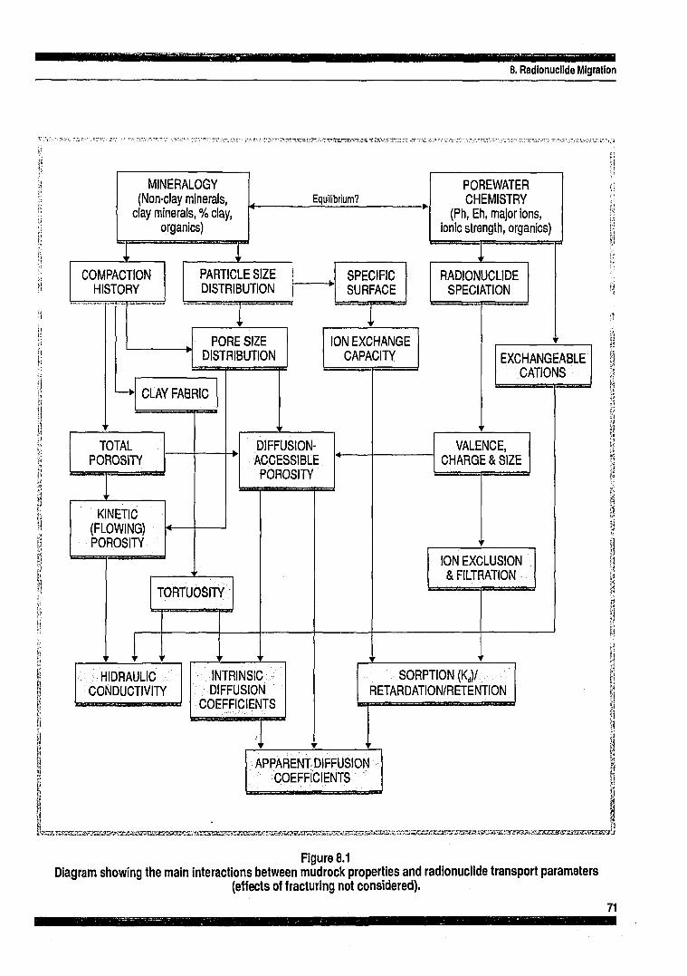
ww 8. Radionuclide Migration
- ^*-^xwxP'7-,V'ii?tzr~-ir < %"
MINERALOGY (Non-clay minerals,
clay minerals, % clay, organics)
COMPACTION HISTORY
Equilibrium?
PARTICLE SIZE DISTRIBUTION
SPECIFIC SURFACE
PORE SIZE DISTRIBUTION
CLAY FABRIC
TOTAL POROSITY
KINETIC (FLOWING) POROSITY
ION EXCHANGE CAPACITY
DIFFUSION-ACCESSIBLE POROSITY
TORTUOSITY
HIDRAULIC CONDUCTIVITY
INTRINSIC DIFFUSION
COEFFICIENTS
POREWATER CHEMISTRY
(Ph, Eh, major ions, Ionic strength, organics)
RADIONUCLIDE SPECIATION
EXCHANGEABLE CATIONS
VALENCE, CHARGES SIZE
ION EXCLUSION & FILTRATION
SORPTION (Kd)/ RETARDATION/RETENTION
amad
APPARENT DIFFUSION COEFFICIENTS
KassHsaEKsssssasassassssssxraxs^^
Figure 8.1 Diagram showing the main interactions between mudrock properties and radionuclide transport parameters
(effects of fracturing not considered).
71

8. Radionuclide Migration
primary migration of hydrocarbons from source rocks (Lindgreen, 1987). During high levels of compaction, adsorbed water is probably shed from clay minerals in discrete layers, each one molecule or roughly 0.3 nm thick. There is a general consensus that, over the depth, pressure and temperature range for oil maturation, the bound water in source-rock shales is only 2 molecular layers thick and that these layers represent most, if not all, of the pore space in the rock (Pepper, 1991). These pores are too small to accommodate many of the hydrocarbon molecules present in crude oil, posing the problem of how the oil manages to escape from the source rock. Size selectivity of the clay filter has also been proposed to explain the anomalous compositions of certain oil accumulations.
Some of the organic matter in clays, notably humic acids, may be dissolved in the porewater. It has been suggested that the amount and the molecular sizes of such compounds found in a particular clay is indicative of the size selectivity of the clay filter Henrion et al. (1991). Since these compounds can form complexes with radionuclides such as Tc, Am, Cm and U and Pu, the capacity of the host-rock to act as a molecular filter is an important consideration. The mobility of organic material in Boom Clay is examined by Put et al. (1991) and the general importance of organics to migration is discussed in Carlsen (1989).
The size distribution of the constituent grains of the rock is a key factor in determining pore sizes and the available surface area for sorption and is likely to have an important influence on most, if not all, of the retardation mechanisms operating in argillaceous rocks. Below clay contents of about 30%, coarser sand- or silt-sized particles will often form a framework of contacting grains which may "shield" the clay minerals from applied stress. In this situation, the interparticle spacings between the platy clay minerals will be significantly greater than would be the case if the same minerals were to be fully stress-supporting. Thus we can expect the largely physical mechanisms of radionuclide retention and retardation (e.g. filtration) to decline rapidly in importance as the fraction of clay minerals drops below 30%.
Radionuclide mobility is strongly dependent on the chemical speciation of the radionuclide in the clay porewater which, in turn, is critically dependent on the chemical composition and pH of the porewater and the redox state of the mineral-porewater system (Higgo, 1987). The decrease in solubility with increasing pH is so marked in certain radioelements
(actinides), that the artificial control of near-field pH offers major advantages. The indications are that cement-based backfills might maintain near-field porewater at pH > 10.5 for extended time-scales. The pH buffering effect of bentonite is less dramatic (pH = 9 in sodium bentonite) and is possibly explained in terms of proton ion exchange reactions (Johnson and Miller, 1984).
There indications are that, at depths well below the weathering zone, many natural clays exhibit neutral to moderately alkaline porewaters (pH 7 -10). Bath et al. (1989) suggest that the pH of the London Clay at Bradwell in S.E. England (generally pH 8 - 10) is the result of the overall hydrochemical evolution of the system, involving both the mass transfer and equilibria of exchangeable cations in the clay and solid-solution carbonate equilibrium. They note that ambient pH in mudrocks may be partly dependent on past salinities; lower salinity environments tend to buffer a higher pH, other factors being equal. Reference groundwater chemistries for Swiss mudrocks reported by Wittwer and McKinley (1989) give pH = 8.5 for the Opalinus clay and pH = 7.5 for the lower fresh-water Molasse. This general alkalinity of the porewater in mudrocks is advantageous in terms of its overall effect on radionuclide mobility.
The phase stability of certain minerals (e.g. iron compounds such as FeS2, Fe2C>3 etc.) present in the mudrock can provide useful information on Eh - pH conditions prevailing at depth (Garrels and Christ, 1965; Henrion; Ind Fonteyn, 1984; Bath et al. 1989).
Finally, as discussed in Chapter 4, the rock mass characteristics of the mudrock (joints, fissures, faults etc.) are an important consideration in radionuclide transport. In the more indurated mudrocks, it is possible that the movement of groundwater and solute occurs primarily in these discontinuities. Since groundwater flow velocities will generally be greater for fracture flow and the surface area available for sorption will generally be smaller, the residence times of radionuclides migrating in a discontinuous rock mass may be substantially less than in the case of a homogeneous (unfractured) mudrock.
8.2.2 Radionuclide Speciation
The importance of the chemical speciation of radionuclides under in situ conditions has already been emphasized. The following general observations on the speciation of "critical" and "possibly critical" radionuclides in mudrocks are drawn largely from work on the Boom Clay, which is summarized
72

8. Radionuclide Migration
in De Preter et al. (1991; 1992). The in situ water content of this clay is in the range 18 to 29 wt-%. The "interstitial" porewater in fresh (unoxidized)- Boom Clay has low ionic strength (= 5 x 10'*' M), the predominant ions are Na+ and HCO3- and the water is alkaline with pH = 9. The presence of pyrite is indicative of the reducing conditions (Eh = -300 mV) at typical repository depths in this material (Henrion and Fonteyn, 1984; Baeyens et al. 1985).
The speciation of l4C in the clay environment is generally not well know, but possible vectors are HCO3-, which is not retarded by sorption, together with light organic molecules (CH4, etc.). The PACOMA (1991) study underlines the requirement for further work on the speciation and transport of l4C in mudrocks.
Technetium is known to exist in valence states from I to VII. In oxidizing groundwaters it is present as the pertechnetate ion TcCV, which is very poorly sorbed (Higgo, 1987). The possible Tc-species in the reducing environment of the Boom Clay are Tc02.2H20 or TcO(OH)2 and organic molecules. Tc, as well as Am, Cm, U and Pu, can be strongly complexed with organic molecules emphasizing the requirement for detailed studies of the organic content of the clay and on the mobility of organic molecules.
Iodine would be expected to form negative ions in the groundwater environment (mainly I-). Thus ml may be expected to be poorly sorbed by most minerals, since anion sorption is usually low. However, due to the negative charge on the clay mineral surface, it is probable that anions will be largely excluded from the smaller, interparticle pores of a mudrock (Bourke el al. 1989; Henrion et al. 1991). Iodine is exclusively present as I- in the Boom Clay. As a poorly-sorbed and long-lived species, nyI constitutes a particularly important radiological hazard.
Caesium is likely to be exclusively present as Cs+
and its behaviour in clays is generally determined by ¡on exchange processes and is therefore sensitive to changes in ionic strength and cation exchange capacity (Higgo, 1987). The most selective sites for l35Cs sorption is thought to be the charged frayed edges of clay minerals (Sawhney, 1972; Cremers et al. 1988).
Neptunium speciation in Boom Clay has yet to be fully elucidated. Np (IV) is a probable oxidation state in the clay environment and, although it forms only weak organic complexes, transport in this form cannot be completely ruled out. Overall 237Np sorp
tion in Boom Clay is probably controlled by a strong specific sorption on oxide-like surfaces (Henrion et al. 1990).
No evidence of humic complexation has been found for selenium. The main species of 79Se in Boom Clay are probably metallic Se and HSe\ The importance of Pd has recently been recognized and no speciation studies have not yet been undertaken.
Due to the complex chemistry of uranium, the speciation of 235U and 236U in the clay environment is poorly understood. The ratio of mobile (extractable) uranium in the clay to uranium in the associated porewater is suggestive of high sorption and low mobility in the Boom Clay, which" is supported by measurements of uranium isotope ratios (Yoshida et al. 1991). Complex formation with low molecular weight organic compounds may be a factor in determining the mobility of the transuranic actinides Pu, Am and Cm.
8.2.3 Effects of Near-Field Evolution
The post-closure chemical evolution of the near-field of an HLW (vitrified waste) repository in argillaceous rock has been examined by McKinley (1985). The discussion is based on the "in-tunnel" disposal concept and it is assumed that the tunnel liner could be withdrawn after waste emplacement. The main mechanisms and processes considered are:
• Local destressing and desaturation of host-rock B Local oxidation of host-rock • Resaturation and buffer swelling • Development of thermal field • Hydtothermal alteration of buffer • Canister corrosion and failure • Leaching of waste-form • pH - Eh buffering • Sorption on corrosion products and buffer clay • Radionuclide transport to the far-field During the repository development and operational
phases, regions of the host-rock become unsaturated, destressed and partially oxidized. Acidic waters may result from pyrite oxidation (if present), causing rapid corrosion of structural materials and, possibly, alteration and dissolution of minerals in the host-rock.
Water re-invades zones of the repository host-rock which have been partially drained during the operational phase. The hydrology of the host-rock begins to stabilise and the bentonite buffer begins to adsorb
73

8. Radionuclide Migration
water and swell. The tunnel begins to collapse against the backfill after (assumed) removal of the liner.
The gradual wetting of the buffer is coupled to spreading of radiogenic heat from the waste through the buffer. After a thermal peak, which occurs within the first few years, the temperature profile through the bentonite and surrounding rock gradually decays away over a period of several hundred years, in line with the decrease in thermal output from the waste. During the same time period, the bentonite becomes saturated and exerts a swelling pressure on the surrounding rock and the waste package, closing any construction gaps.
Oxidation of the host-rock may perturb the chemistry of the initial water inflow into the near-field (e.g. pyrite oxidation to give pH = 3). In addition, from first wetting, hydrothermal alteration of backfill (e.g. smectite to illite) will commence, the rate of which will be controlled by reaction kinetics (temperature dependent) and the rate of supply of particular solutes (e.g. K+). Corrosion of the cast steel canister will occur, which will initially be oxic but quickly become anoxic as trapped air is used up. The rate of corrosion may be affected by the build-up of layers of solid reaction products (oxy-hydroxides) or by the limiting rate of supply of corrodents or loss of dissolved or gaseous products by diffusion through the backfill.
After the canister has been corroded to a certain extent, it will fail mechanically (>103 years from closure) and water will then contact the waste matrix. Even after canister failure, however, continued corrosion of unreacted iron and buffering by corrosion products will exert an influence on the chemistry of the water in contact with the waste glass.
Corrosion of the vitrified waste will occur by a process of congruent dissolution with some associated precipitation of secondary mineral phases. Preferential leaching of particular nuclides occurs in the very early stages of corrosion. During steady-state leaching, the rate of release of specific nuclides would be controlled either by the rate of glass matrix dissolution or by limits set by the total solubility of the element in question under prevailing Eh - pH conditions.
The leachate thus formed is transported to the far-field by diffusion through the remnant canister and corrosion products and the bentonite backfill. The rate of such transport will be dependent on diffusion rates in the bentonite pores, the magnitude of retardation processes occurring (e.g. sorption,
ion-exclusion, etc.) and on the groundwater flux in the host-rock around the emplacement tunnels.
It is apparent that the presence of a substantial ferrous metal or concrete tunnel liner could have very significant effects on chemical evolution and near-field fluxes. Gas production and migration are discussed in Chapter 9.
8.3 Advection/Dispersion Model
The quantitative approach to the prediction of radionuclide transport in porous media is based on the conventional advection/dispersion model (Freeze and Cherry, 1979). In this model, far-field radionuclide migration is quantified by a number of hydrogeological and chemical parameters:
• Average linear velocity of groundwater • Porosity (appropriately defined) n Coefficient of hydrodynamic dispersion • Retardation factor • Radioactive decay constants
The transport equation is obtained by considering the mass balance within an element of unit volume within the porous medium. The effect of the in-growth of daughter products of radioactive decay may be included. A one-dimensional form of this equation is discussed in this section.
8.3.1 Dispersion
As a contaminant move through a porous medium it tends to spread out from the path predicted by considering advective hydraulics alone. This spreading phenomenon is called hydrodynamic dispersion and was first considered by Taylor (1953). The process of hydrodynamic dispersion occurs as a result of mechanical mixing and molecular diffusion.
Mechanical dispersion and mixing is a largely a consequence of the essentially inhomogeneous nature of flow in a porous medium. When a succession of water molecules moves from one region to another region of such a medium, then no two molecules will follow precisely the same path. Differences in path length, resistance to flow and velocity of flow along near-parallel paths results in variability in the time taken for the molecules to traverse an equal distance. Contributions to the mechanical dispersion arise from
a) flow velocity variations within individual pores due to the viscous drag exerted adjacent to the pore walls,
74

b) differences in the pore sizes along the flow paths and
c) the tortuosity, branching and interfingering of pore channels. In fractured media, flow along paths of interconnected fractures results in very similar dispersion effects.
Dispersion is an exceedingly complex and poorly understood process. Qualitatively, mechanical and diffusive dispersion have similar effects and are usually modelled using a diffusion-like term, with the dispersive flux taken to be proportional to the concentration gradient. The physical constant which quantifies these effects in a given porous medium is termed the "coefficient of hydrodynamic dispersion" D (nr.s1).
At low groundwater flow velocities, diffusion is the dominant mechanism of dispersion and therefore the coefficient of hydrodynamic dispersion approximates to the coefficient of molecular diffusion. The Peclet number can provide a measure of the relative importance of the two dispersion mechanisms (Freeze and Cherry, 1979; de Marsily, 1986). Calculations of the Peclet number for Boom Clay are presented in De Preteretal.(1991).
In general three-dimensional problems the coefficient of hydrodynamic dispersion is a tensor quantity. However, in analyzing problems in two-dimensions it is customary to define two separate coefficients. The spreading of the solute in the direction of the bulk flow is termed longitudinal dispersion and is quantified by the coefficient of longitudinal dispersion. One of the characteristic features of the dispersive process is that it also causes spreading of the solute in directions perpendicular to the flow path, known as transverse dispersion. The corresponding physical constant is the coefficient of transverse dispersion. Longitudinal dispersion usually exceed transverse, but at low velocities, with diffusion as the dominant dispersion mechanism, the coefficients of longitudinal and transverse dispersion are nearly equal.
In contaminant transport, dispersivity is probably the most difficult parameter to quantify. Longitudinal dispersivity can be obtained in the laboratory from the analysis of break-through curves obtained from column experiments on undisturbed samples using nonreactive tracers. However, scale effects are likely to have a pronounced effect on dispersion and the results obtained on small samples in the laboratory must be viewed with the greatest of caution. In general, dispersion coefficients inferred from field
8. Radionuclide Migration
observations are significantly larger than those obtained in the laboratory.
8.3.2 Advection Term
In advective transport, contaminants are carried in solution at a rate equal to the average linear velocity of the groundwater. This transport mechanism is sometimes referred to as convection. According to Darcy's Law, the specific discharge v<i (m.s"1), also termed the Darcy velocity, is given by
v d = - Q / A = - K § (8.D
where Q (nr'.s'1) is the rate of flow of water through an area A (m2) perpendicular to the direction of flow, K is the hydraulic conductivity (m.s"1), h is the hydraulic head (m) and x is distance along the flow path (m). The average linear velocity v of the groundwater is then given by
v = v d /n (8.2)
where n is the (appropriately chosen) porosity. The rate of change of mass of radionuclide species-i in solution within an element of unit volume due to advective transport out of the element is
-n v t £ (8.3) ox
where Cw (kg.m"3) is the concentration of the radionuclide in the groundwater.
8.3.3 Dispersion Term
Making no distinction between "flowing porosity" and "diffusion accessible porosity" (see Put, 1984), the rate of change of mass of radionuclide species-i in solution within the volume element due to dispersion is
-n|{-D& M dx ' ox '
The coefficient of hydrodynamic dispersion D can be expressed as
D = a I v I + D* (8.5)
where a is a property of the porous medium known as the dispersion length (m) and D* is the "porewa-ter" diffusion coefficient (m2.s"') for the particular radionuclide species and medium (Fried and Combarnous, 1971; Bear, 1972; Scheidegger, 1974). It is generally observed that the dispersion length is related to the length-scale of the heterogeneities in a
75

8. Radionuclide Migration
porous medium and increases somewhat for long distance solute transport since the heterogeneities affecting the process become larger (Lallemand--Barres and Peaudecerf, 1978; Neretnieks et al. 1987). Put et al. (1991) report a dispersion length a = 1 x 10"3 m for Boom Clay, based on laboratory experiments on undisturbed clay cores.
8.3.4 Radioactive Decay Terms
Radioactive decay during transport can be described in terms of irreversible reactions. The rate of change of the mass (in solution) of radionuclide species-i due to decay is
-n X¡ Q (8.6)
per unit volume of porous medium, where X, is the decay constant (s"1) and Ci (kg.m"3) is the concentration of species-i in the groundwater. The decay constant can be calculated from the radionuclide half-life T (s) by X = 0.693/T. The rate of change of mass of radionuclide species-i, due to in-growth from species-j can be expressed in a similar way as
+ n AjCj (8.7)
8.3.5 Transport Equation for Non-Sorbing Species
The rate of change of mass of radionuclide species-i in solution within the element, due to all processes, is
n * i (8.8)
Mass conservation demands that (8.8) is equal to the sum of terms (8.3), (8.4), (8.6) and (8.7). With the assumption that D does not vary in the x-direction, the basic one-dimensional transport equation for a non-sorbing species is obtained
8.3.6 Sorption and the Distribution Coefficient
The distribution coefficient K (m .kg ) may be defined as the mass of the radionuclide which is bound to the solid phase per unit mass of the mineral solids, divided by the mass remaining in solution per unit volume of groundwater.
K, = (mn„ / m j / (mw / Vw) (8.10)
where m^ is the mass of radionuclide sorbed on mineral solids with a mass of mm and mTO is the mass of radionuclides in volume Vw of groundwater solution. The mass of radionuclides sorbed on mineral solids per unit volume of the porous medium can then be expressed in terms of the groundwater concentration
(mm, / V.) = p8 (1 - n) Kj Q = pb n Kd Q (8.11)
where p„ is the grain density of the mineral solids (= mm/Vm), pi, is the saturated bulk density of the porous medium (= m, / V,), Vm is the volume of mineral solids and m, and V, are the total mass and total volume of the element of the saturated porous medium, respectively.
Kd is a valid representation of the partitioning between liquid and solids only if
a) the reactions that cause the partitioning are fast and reversible and,
b) the isotherm is linear. The sorption properties of the Mesozoic clays
beneath Harwell in Oxfordshire have been discussed by McKinley and West (1984) and sorption in the London Clay is examined by Berry et al. (1989) and Ivanovich et al. (1988). Cunent data for the Boom Clay are summarized by De Preter et al. (1992).
8.3.7 Transport Equation including Sorption
The rate of change of mass of radionuclide species-i sorbed to mineral solids within the element of unit volume considered above is
., . v 3Ci (8 12) pg ( 1 - n ) K j ; - ^ - (0-L~>
where Kd¡ is the distribution coefficient applicable to radionuclide species-i. The rate of change of the mass of radionuclide species-i sorbed to mineral solids due to decay is
- p g ( l - n J K t f X i Q (8.13)
The rate of change of mass of species-i sorbed to solids due to in-growth from species-j is
+ pg ( 1 -n ) Kdj \ Cj (8.14)
Mass conservation requires that, after dividing by n, these three terms (8.12), (8.13) and (8.14) are subtracted from the right hand side of (8.9). Rearranging the terms, the one-dimensional transport equation for
76

8. Radionuclide Migration
a sorbing radionuclide species-i, including in-growth from species-j, becomes
R i f i = ü | p - v ^ - R ^ i C ¡ + RiXjCj (8.15)
where R¡ is the "retardation factor" for species-i, defined by
Ri = [ l + - ^ J 1 p g K d J (8.16)
The three-dimensional generalisation of (8.15) is easily obtained. An excellent account of radionuclide chain transport assuming matrix diffusion and norlinear sorption is given in Jacob et al. (1989).
8.3.8 Source Term
The source term is added to Equation (8.15) to represent the timing and rate of release of radionuclides from the waste-form. Specification of a realistic source term requires careful consideration of the evolution of the near-field environment including factors such as the failure of the waste canisters due to corrosion, mechanical damage or other mechanisms, the degradation of the other near-field barriers, the leaching of radionuclides from the waste matrix and the solubility of the various radionuclide species in the porewater. Physico-chemical conditions in the near-field (temperature, redox potential Eh, pH, major ion concentrations, etc.) exercise important controls on both radionuclide mobility and the rate of degradation of the engineered barriers.
8.3.9 Solutions
Numerous analytical solutions have been obtain for the transport equation in one-, two- and three-dimensional space for a number of idealized source term functions (Fried, 1975; Bear, 1979; Harada et al. 1980; Pigford et al. 1980; Javendel et al. 1980; Put, 1984; de Marsily, 1986). Most neglect the radioactive decay terms.
Sensitivity analyses of transport in "plastic" clays have identified the diffusion coefficient and the distribution coefficient as the most important parameters affecting transport in clays (Bonne and Heremans, 1981; de Marsily et al. 1977; Klett, 1983). Scoping calculations provide a simple and cost--effective way of assessing the performance of the
geological barrier during the early stages of site appraisal. Risk calculations may be performed for a range of "critical" radionuclides, assuming simplified hydrogeology, and based on (assumed) drinking water abstraction from a nearby, critically-located, water well.
8.4 Diffusion in Mudrocks Given the general importance of diffusion as a
transport mechanism in unfractured and generally more plastic argillaceous host-rocks, the factors affecting the coefficients of diffusion of radionuclide species in the clay environment are of particular interest.
Non-sorbing species diffusing through the solution-filled pore spaces of a rock encounter along their path an irregular network of pore channels and they frequently collide with the walls of these channels. Diffusion through this porous space is slower than it would be in the absence of the mineral framework. The physical characteristics of a rock that are responsible for slowing down molecular diffusion are considered to be the porosity itself, the pore-size distribution (represented by a constrictivity term) and the tortuosity of the diffusional path. Tortuosity 0 is defined as the ratio of the mean length path Lp through the porous space between two points to the straight line distance L:
9 = L p / L (8.17)
The intrinsic diffusion coefficient Din, of a non-sorbing species can then be related to the free water diffusion coefficient Do by
Dim = n(8/62) D0 = nD* (8.18)
where n is the porosity (appropriately defined), 8 is the constrictivity and D* is the "porewater" diffusion coefficient of Equation (8.5). Since the value of D0 is
' generally well known or can be calculated with good precision from fundamental principles (e.g. Stokes-Einstein relationship), Equation (8.18) provides a useful basis for the prediction of diffusion coefficients for mudrocks.
The apparent coefficient of diffusion Dapp (nr.s'1) of a sorbing radionuclide species migrating in a mudrock may be written as
77

m
where R is the retardation factor and Rr is the "rock factor" which is used in the Belgian studies of radionuclide migration (Put, 1984).
In studies of the flow of electrical current (ions) in porous media, the formation factor f is defined as the ratio of the electrical conductivity Kw (mhos) of the bulk groundwater to the electrical conductivity of the saturated porous medium Kp (mhos). A number of expressions have been developed relating formation factor to porosity and one general fomi is
f = ( n f (8.20)
where n is porosity and m is Archie's exponent (cementation factor). Experimental data suggest n to be approximately 1.3 for unconsolidated sands, 2 for sandstones and 2.5 to 5.4 for clays. For uniform non-conducting spheres n is 1.5, in which case (8.19) is often referred to as the Bruggeman equation.
Henrion et al. (1991) show that an analogous formation factor f may be defined for radionuclide migration in the Boom Clay
f = Rr/ii (8.21)
where rj is the "diffusion accessible porosity". By analyzing the results of flow-through diffusion experiments using "non-sorbing" I- and HTO (tritia-ted water) in sodium bentonite compacted to varying degrees, Henrion et al. (1991) have shown that
H D* = 6.84- 10"10(il)'y- (m2-s_1) (8.22)
This closely resembles the Bruggeman equation and suggests that the decreased mobility of small neutral molecules and anions, under compaction, is solely the result of changes in diffusion accessible porosity. Additional studies on the effects of compaction on the migration of charged particles and labelled water are reported by Grauer (1986) and Relyea et al. (1986). The underlying mechanisms would appear to be molecular filtration and anion exclusion in the smaller inter-particle spaces of the clay.
The apparent coefficient of diffusion Dapp for a sorbin" radionuclide species may be expressed in tenns of these two additional parameters by
Three separate effects on DaPP are apparent in Equation (8.22). These are:
a) radionuclide/mineral interaction effects (sorption), represented by the retardation factor R,
b) pore-size limitations on radionuclide access to pore space, represented by r) and,
c) clay fabric effects largely due to the tortuosity of the diffusion pathways, represented by f.
In theory at least, f should be a property of the particular mudrock and should be independent of the diffusing species. De Preter et al. (1991) report the diffusion accessible porosity of Boom Clay under in situ conditions to be 0.087 for I" and 0.34 for HTO, which compares with a total porosity of about 0.4 for this clay.
The final issue in this brief review is surface diffusion. As has already been observed, in well-compacted mudrocks (and bentonite backfills) the larger part of the water present is probably structured water adsorbed to clay minerals. In these circumstances specifically bound cations in the inner Helmholz plane may have discernable mobility. This mechanism has been invoked to explain the unexpectedly high diffusion rates of ions such as Cs+
and Sr2+ in compacted bentonite (Neretnieks, 1982; Soudek et al. 1988). Thus, there may be two parallel paths for ¡on diffusion, the first through loosely held water generally more remote from clay surfaces, and the second through the adsorbed layers in close proximity to the clay surfaces (Charles et al. 1986; Muurinen et al. 1986; 1987). The surface diffusion mechanism in clays remains a matter of controversy. One interesting though on this issue is that, in very highly compacted and indurated mudrocks (e.g.: hydrocarbon source rocks), in which all water present is undoubtedly structured, surface diffusion may represent the only mechanism of solute transport that can operate in the absence of fracturing.
78

9. Gases and Gas Migration
GASES AND GAS MIGRATION
ú '0

• am 9. Gases and Gas Migration
A range of gases will be produced by chemical reactions, microbial degradation, radiation effects and other processes occurring within the waste, at the surface of containers, in the buffer/backfill medium and host-rock and elsewhere in the repository. The generation of gases in the repository environment is of concern for a number of reasons:
B Pressurization of waste containers • Perturbation of groundwater flux • Effect on repository backfill and seals • Effect on host-rock transport properties • Effect on heat dissipation • Release of active gases
It is generally agreed that gas migration along the pathway of the backfilled repository access ways (tunnels, drifts and shafts), or up-hole in the case of deep borehole emplacement, is to be avoided since active gases might be released to the biosphere via this "preferential path" and contaminated groundwater could be displaced along this route by "gas-drive".
It seems highly unlikely that the high integrity seals constructed at key points in the repository could be engineered to withstand a substantial differential pressure for an extended time-period. The development of a gas pressure within the repository which is substantially higher than the (unperturbed) groundwater pressure at that depth is therefore unacceptable. Although pressure venting has been considered as a method of preventing gas pressure build-up, it has the obvious disadvantages that
a) active gases are released, and
b) the venting arrangements may provide an easy pathway for groundwater movement.
In the ideal situation, gas would be transported away from the repository in solution by advec-tion/dispersion within the groundwater of host-rock. Furthennore, attenuation mechanisms (e.g. sorption and chemical reactions) in the host-rock would result in depletion of the flux of gas in solution so that, at some distance from the repository, the radiological significance of the flux would be minimal. There is an irony in the fact that the sought-after characteristic of the clay host-medium of very low permeability becomes somewhat problematic in the context of gas migration. As has already been noted, under normal circumstances the flux associated with advective transport in compact clays is likely to be quite small and the dispersion mechanism is likely to be dominated by Fickian diffusion.
Calculations of the probable maximum diffusive flux of gas (in solution) in a clay suggest that Fickian diffusion in the host-medium may be too slow a mechanism to accommodate the quantity (and rate) of gas produced in a repository (Lever and Rees, 1987). This is, of course, highly dependent on specific details of the repository design and the waste inventory. Nevertheless, there is a strong possibility that a gaseous phase might form in available void-space within a repository in clay. If this is indeed the case, then at least some rise in gas pressure is inevitable. Figure 9.1 summarizes some of the main interactions.
9.1 Gas Generation Although small amounts of gas are developed by
radioactive decay of the waste, the principal mechanisms of gas generation (Voinis et al. 1992) are:
• Corrosion of metals • Radiolysis of water and other materials • Microbial and chemical degradation of
organ ics • Thermal release (T > 100°C)
9.1.1 Corrosion
Anoxic corrosion of metals, in particular of ferrous metals, is a major potential source of hydrogen. These metals may be present as a component of the waste or may have been used in waste packaging or in repository engineering (e.g. gallery linings and overpacks). The main chemical reactions are:
3 Fe + 4 H20 <—> Fe,04 + 4 H , (9.1)
Fe + 2 H ;0 <—> + Fe(OH)2 + H2 (9.2)
These reactions are specific to anoxic conditions but do not occur simultaneously. Corrosion may be a generalized or local. The rate of corrosion depends on the nature of the steel, the availability of water, the chemical environment (pH, Eh, etc.) and on temperature.
The rate of hydrogen production (mole.year-1) is directly proportional to the corrosion rate and the total surface area of ferrous metal subject to corrosion. Where groundwater fluxes are low, the availability of water might be a rate-limiting factor. If the host-rock becomes temporarily unsaturated due to gas production, then cyclic behaviour might occur.
81

9. Gases and Gns Migration
£W&iriW^&b¿íiroi^^
Figure 9.1 System diagram showing some of the main interactions associated with gas production and migration
(clay repository).
82

9. Gases and Gas Migration
9.1.2 Radiolysis
Gamma radiation can penetrate the wall of a waste canister to produce radiolysis of the surrounding groundwater (Christcnsen and Bjerbakke, 1985). The effect depends on the nature of the ions in the water, pressure, pH, dissolved gases, dose rate and integrated dose. Near-field radiolysis produces H2, 02, C02, and CH4, together with HCl, and Cb in brines. Radiolysis effects in the Boom Clay have been discussed by Put and Henrion (1990).
Radiolysis gases such as H2 can also be produced inside the canisters largely due to gamma irradiation of the waste matrix, with a smaller contribution from beta irradiation.
9.1.3 Microbial and Chemical Degradation of Organics
Where organic materials have been incorporated in the waste or have been used elsewhere in the repository, then the decomposition of these materials by chemical or microbial action will produce gases such as CO2 under aerobic conditions and, primarily, CH4 once all available oxygen has been consumed.
9.1.4 Other Mechanisms
Helium is produced by alpha decay associated with actinide wastes. Radioactive gases are of two types: fission products such as l29I,3H, l4C, 85Kr and the decay chains 220Rn and 222Rn. Isotopic exchange, such as l4C for l2C, will render other gases radioactive.
Near-field temperatures significantly greater than 100°C may also cause water to boil, releasing steam as an additional gaseous phase. This mechanism is generally referred to as "thermal release". Naturally--occurring gases such as CH4 may also be present.
9.2 Gas Migration in Mudrocks
Tomlinson (1988) has undertaken a comprehensive review of the literature on the migration of gases in argillaceous media. Possible mechanisms are:
• In solution by advection/dispersion (diffusion dominated)
• As a gaseous phase in 2-phase (porous media) flow
• As a gaseous phase in preferential pathway flow
In fissured or jointed mudrocks, gaseous phase flow might also occur within the discontinuities (Rodwell, 1989). In clays which are not naturally fractured, there is also the possibility of gasfracturing caused by excessively high repository pressures. This is regarded as highly undesirable and emphasizes the need for fundamental research on gas transport in low permeability media.
Laboratory experiments on gas transport in bentonite have been reported by Pusch et al. (1985) and on intact clay samples by Lineham (1989). Some preliminary results are available for Boom Clay from the CEC Megas Project (Volckaert et al. 1992). Some general conclusions, to date, are
a) transport in solution is too slow to account for typical gas production rates and a gaseous phase will form in the repository,
b) during 2-phase flow, the relative gas--permeability of the clay (with argon as the permeant) is a function of saturation and is effectively zero at water saturations exceeding about 90%,
c) if the gas pressure difference across the sample is raised, "breakthrough" will occur which is apparent as a sudden increase in gas flux,
d) breakthrough pressures correlate well with hydraulic conductivity and are lower in a direction parallel to bedding than normal to it. Breakthrough pressures of 1-1.5 MPa are measured for How parallel to bedding under typical in situ stress condition.
Although all saturated porous media display a Ihreshold pressure for gas entry into pores, associated with capillary effects, breakthrough in a highly defor-mable medium such as a clay is likely to be subtly different, producing local deformation of the clay fabric along the pathway. The changes in effective stress associated with gas penetration are potentially large and local effects on fabric (e.g. bending and separation of clay platelets) are to be anticipated. Modelling, using standard 2-phase flow codes, is probably premature, since the micro-mechanics of this process are likely to lead to a dependency on in situ stress and clay anisotropy which is not presently represented in these codes.
83

9. Gases and Gas Migration
9.3 General Implications of Gases The radiological risks associated with the gas
migration pathway should be assessed at an early stage, initially on a generic basis, then more rigorously as site-specific data become available.
/// plastic clays and other tight mudrocks, gas production and migration is likely to an important issue, since these rocks cannot easily accommodate the gas flux. If gas production is likely to he significant, then its possible repercussions should examined as an integral pen t of the host-rock I site selection process.
The potential problems of hydrogen production can be minimized, although not necessarily entirely eliminated, by limiting the quantities of mild steel used in repository construction and hy the use of corrosion-resistant steel alloys in areas where the use of ferrous metal is demanded.
Similarly, the anaerobic production of methane can be limited by restricting the quantities of organic materials (cellulose, bitumen, etc.) permitted in the repository. Deep repositories in clay may be unsuitable for cellulosic wastes (LLW).
84

10. Thermal Properties and Responses
THERMAL PROPERTIES AND RESPONSES

10. Thermal Properties and Responses
Heat released from heat-emitting radioactive wastes (vitrified waste, spent fuel etc.) could have important effects on overall repository performance. Although many of these are essentially nearfield effects, occurring within the buffer, backfill and clay host-medium, it is possible that the thermal Field may extent beyond the host-medium to encompass other rock-lypes, possibly having higher permeabilities. In this case, far-field groundwater flow might be affected. Important considerations are:
• Heat dissipation
H Thermally-induced pore pressures • Effect on strength, consolidation, creep, etc. • Development of thermal stresses B Shrinkage (due to heating and drying) • Long-term thermal stability of minerals • Thermo-osmosis, thermo-diffusion and other
mechanisms • Thermo-convection in permeable strata
The maximum near-field temperature increase will depend on the heat output of the waste packages, the thermal properties of the backfill/buffer and the host-medium, and on the distribution and spacing of the waste packages within the repository. Since the thermal properties of materials, including the host-medium, are more or less pre-determined in any repository design, heat-output and waste package spacing are some of the main variables of the design from a thermal perspective. Surface storage is the only practical way of reducing the total heat output of HLW, and options to store for periods of from 25 to 75 years are being examined in the Belgian programme (Put and Henrion, 1991). There may also be some flexibility in waste conditioning and package design to limit the heat output of individual packages, at the expense of increasing the total volume of waste for disposal.
10.1 Geothermal Temperatures
The temperature of the clay host-rock prior to waste emplacement is determined by the geothermal gradient GT which is typically in the range 0.02 -0.O3°C.m"1. Within the clay formation this corresponds to a vertical heat flow approximately in the range 0.032-0.048 Wan"2.
The temperature T (°C) at depth d (m) can be estimated using
T = TI5 + GT ( d - 15) (10.1)
where T15 is the temperature at a depth of 15 metres, which is assumed to be constant throughout the year. Since GT varies from one locality to another and is dependent on lithology, a local value should be determined as part of the site investigation programme.
Taking Ti5 as 15°C, then for a typical repository depth range of 250 to 350 m, the unperturbed in situ temperature will probably be in the range 19° - 25°C.
10.2 Maximum Allowable Temperature
For waste in emplacement boreholes (in-floor concept and DBF concept), the most critical regions, in terms of temperature rise, are likely to be the buffer material, if there is any, and the host-rock immediately adjacent to the boreholes. For the in-tunnel disposal concept, it will be the buffer/backfill material (possibly re-constituted clay or bentonite) and the rock in contact with the external surface of the tunnel lining.
Regardless of the precise details of waste emplacement, it is likely that the host-rock and/or the backfill will, at least locally, be subjected to temperatures which are close to the surface temperatures of the waste packages. The temperature at the most critical point is often referred to as the "maximum spot temperature".
In order to avoid undesirable changes in the containment properties, it is necessary to stipulate a maximum allowable temperature, considering both the buffer/backfill and the particular rock-type. One of the drawbacks of clays as host media for heat emitting wastes is that the maximum allowable temperature is likely to be lower than for other proposed rock-types. In early studies (e.g. Chapman and Tassoni, 1985) this temperature was somewhat arbitrarily set at 100°C, although more recent work tends to suggest that a lower value may be a more appropriate. Detailed studies of the thermo-hydro--mechanical responses of the host-rock and of the thermal stability of the buffer I backfill and host-rock mineral assemblages are required to establish a concept I site-specific value for maximum allowable temperature.
10.3 Heat Transport
The capacity of a host-rock to dissipate the heat generated by radioactive decay is an important consideration in assessing disposal options for
87

10. Thermal Properties and Responses
heat-emitting wastes. Heat flow in a saturated porous rock is governed by four separate mechanisms
a) diffusion of heat through the rock (conduction in solid and liquid phases),
b) heat transport by thermo-convection in the mobile liquid phase,
c) thermal dispersion due to variations in the velocity of the liquid phase and
d) the accumulation of heat in the liquid and solid phases and heat exchange between the phases.
At low groundwater flow velocities, heat exchange between the liquid and solid phases is sufficiently rapid that it is acceptable to assume the temperatures of the fluid and the solid matrix are equal at any point in the porous medium. The heat transport equation is then directly analogous to the solute transport equation (de Marsily, 1986; Cordier and Goblet, 1990).
Based on the conservation of energy, it is possible to write
. div (X grad T - p C v) = p"C"(3T/31) (10.2)
where X is the equivalent conductivity tensor, T is temperature, p and C are the density and specific heat of saturating fluid, p" and C" are the (bulk) density (kg.m'3) and specific heat (J.kg"'.K'') of the saturated rock, v is the average linear velocity and t is time. The product p" C" is the volumetric heat capacity (J.m .K'1) of a saturated porous medium and is given by
p"C" = n p C + (1 -n) p ' C (10.3)
where p' and C are the (grain) density and specific heat of the mineral solids, and n is the fractional total porosity. Typical values are given in Table 10.1.
The equivalent conductivity tensor X combines the isotropic conductivity Xo of the saturated porous rock, in the absence of flow, with a term for the macrodispersivity which is a linear function of the absolute value of the average linear velocity v
XL = X.„ = A0 + p L p C M (10.4)
Xr = 2̂2 = ^3 = Xo+ PT P C M (10.5)
where Xn, X2i and X3i are the principal components of X and p\ and |}T are the longitudinal and transverse thermal dispersivities. It is possible to derive a thermal equivalent of the Peclet number which can be
used as a guide as to the relative importance of the dispersion mechanism (de Marsily, 1986).
/// muclrocks, the average linear velocity is usually so small that the thermo-convection and thermo-clispersion mechanisms can he ignored and heat flow is dominated by diffusion (pure conduction) (Put and Henrion, 1990). However, these additional mechanisms may be highly significant within the more permeable non-clay strata of a sedimentary succession. Thermo-convective heat transport and groundwater fluxes in the formations overlying the Boom Clav has been modelled by Cordier and Goblet (1987).
The thermal diffusivity DT (nr.s'1) is often quoted and is given by
DT = X,/ (p"C") (10.6)
where XQ is the thermal conductivity of the saturated medium (with the fluid at rest).
10.4 Thermal Properties
Mudrocks have a somewhat lower thermal conductivity than other potential host-rocks, approximately one-half that of sound granite and a quarter that of rocksalt (Table 10.1). This, together with the lower maximum allowable temperature, will dictate a lower repository thermal loading than would be acceptable in the other rock-types. In effect, the waste canisters must be more widely spaced in a mudrock.
Guidelines on the typical thermal conductivities can be obtained from Bloomer (1981), who tabulates experimental values for a range of British mudrocks. Selected values are given in Table 10.1 Robins et al. (1983) also report thermal conductivity data for the Mesozoic mudrocks encountered in the HW3 borehole which was drilled at UKAEA Harwell Laboratory in Oxfordshire, England. Laboratory experimental methods have been described by Von Herzen and Maxwell (1959), Sass et al. (1971) and Bloomer and Ward (1979), amongst others.
Additional thermal data are also available from the Belgian radioactive waste disposal programme. Analysis of a heat transfer test in a clay pit at Terhagen gives a thermal conductivity of 1.69 W.m"'.°C , a volumetric heat capacity of 2.83 x 10⁶ J.m'VC"1 and a thermal diffusivity of 5.96 x 10'7 m2.s"' (= 18.8 m2.y"') for Boom Clay with a bulk density of 2.0 Mg. m*1 and a moisture content of 18 wt-% (Buyens et al. 1984).
88

10. Thermal Properties and Responses
Table 10.1 Thermal properties of water and selected soils and rocks (from de Marsily, 1986).
Material
Water
Dry sand
Wet sand
Dry clay
Wet clay
Granite
Rocksalt
Thermal conductivity Xo .(W.m-l'C'')
0.598
0-4 - 0.8
2.5 - 3.5
0.8-2.0
1.2-1.7
2.5-3.8
5.86
Volumetric heat capacity p" C" (J.m-?C-')
4.185 x10s
1.9 x10⁶
1.9x10⁶
2.1x10s
2.3x10s
2.1x10s
2.0x10s
Table 10.2 Thermal conductivities of mudrocks from central southern England (selected values
from Bloomer, 1981).
System
Cretaceous
Jurassic
Triassic
Formation /
Gault (clay)
Kimmeridge (clay)
Oxford Clay
Lower Lias (clay)
Keuper Marl
Method
PB
NP/PB
BP
NP/PB
NP/PB
No. of values
4
58
11
37
41
Thermal conductivity (W.rrfVc4)
1.67 ± 0.10 0
1.51 ± 0.09 (")
1.57 +0.03 (**)
1.80 +0.10 (")
2.28 ± 0.33 (**)
Abbreviations: NP = Needle probe method; PB = Pill box method.
(*) Standard error calculated from variation within one borehole
(**) Standard error from variations between boreholes
10.5 Thermally-Induced Pore Pressures
The effects of heating on the pore water pressures in argillaceous rocks are very complex. Since water content is a significant factor in determining the magnitude of these effects, it is worth noting that the water content of potential repository host rocks may vary from, say, 20 wt-% in a typical plastic clay to less than 8 wt-% in a more indurated clayshale. In the
more indurated rocks, a significant proportion of the water is also adsorbed on clay mineral surfaces.
Heating produces thermal expansion of the free water, adsorbed water and mineral phases in the rock and may also produce changes in the thickness of the adsorbed water layers. A detailed account of these mechanisms is given in Baldi et al. (1991). The thermal expansion of "free" water is temperature dependent and can be estimated using the following relationship.
89
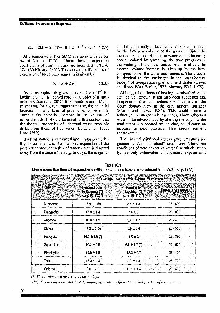
10. Thermal Properties and Responses
a,,, = [200+ 6.1 (T-10)] x 10"6 CC') (10.7)
At a temperature T of 20°C this gives a value for ce,, of 2.61 x 10",oC'1. Linear thermal expansion coefficients of clay minerals are presented in Table 10.1 (McKinstry, 1965). The cubical coefficient a, of expansion of these platy minerals is given by
a, = oc, + 2 a2 (10.8)
As an example, this gives an a r of 2.9 x 10'5 for kaolinite which is approximately one order of magnitude less than a„. at 20°C. It is therefore not difficult to see that, for a given temperature rise, the potential increase in the volume of pore water considerably exceeds the potential increase in the volume of mineral solids. It should be noted in this context that the thermal properties of adsorbed water probably differ from those of free water (Baldi et al. 1988; Low, 1989).
If a heat source is introduced into a high permeability porous medium, the localized expansion of the pore water produces a flux of water which is directed away from the zone of heating. In clays, the magnitu
de of this thermally-induced water flux is constrained by the low permeability of (he medium. Since the thermal expansion of the pore water cannot be easily accommodated by advection, the pore pressures in the vicinity of the heat source rise. In effect, the thermal volume increase is taken up by the local compression of the water and minerals. The process is identical to that envisaged in the "aquathermal theory" of overpressuring of oil field shales (Lewis and Rose, 1970; Barker, 1972; Niagara, 1974; 1975).
Although the effects of heating on adsorbed water are not well known, it has also been suggested that temperature rises can reduce the thickness of the Gouy double-layers at the clay mineral surfaces (Morin and Silva, 1984). This could cause a reduction in interparticle distances, allow adsorbed water to be released and, by altering the way that the total stress is supported by the clay, could cause an increase in pore pressure. This theory remains controversial.
The thermally-induced excess pore pressures are greatest under "undrained" conditions. These are conditions of zero advective water flux which, strictly, are only achievable in laboratory experiments.
Table 10.3 Linear reversible thermal expansion coefficients of clay minerals (reproduced from McKinstry, 1965).
'-"'"''st"-"- 'Mineral «•""'>• •'• - • > : , - . - - " • / • - * - - , •
Muscovite
Phlogopite
Kaolinite
Dictóte
Halloysite
Serpentine
Pirophyllite
Talk
Chlorite
Average linear thermal expansion coefficient.' >io''\JSs,\ / ,<-
*'•-•' Perpendicular ' to layering (")
- - a i x 1 0 6 ( ° c n
17.8 + 0.59
17.811.4
18.6 + 1.3
14.9 ±0.84
10.0 + 1.50
10.2 ±0.9
14.9 ±1.8
16.3 ±2.4"
9.0 ±2.3
Parallel to i,<*-? layelingr): " * \
a2XlOTC"J) , -
3.5 ±1.3
14 + 3
5.2 ±1.7
5.9 ±0.4
6.0±2
6.9 + 1.7 0
12.2 ±0.7
3.7 ±1.4
11.1 ±1.4
Temperature range
25 - 600
25-350
25 - 400
25 - 500 J
25 - 350
25 - 500
25 - 400
25 - 700
25 - 500 |
(*) These values are suspected to be too high (**) Plus or minus one standard deviation, assuming coefficient to be independent of temperature.
90

10. Thermal Properties and Responses
where A u is the increment in pore pressure, A T is the increment in temperature, o' is the effective stress acting on the clay, e0 is the initial voids ratio, as is the cubical thermal expansion coefficient of the mineral grains, a,,, is the thermal expansion coefficient of the porewater, n is the porosity and Cs is the swelling index of the clay (a standard soil mechanics parameter). The cubical thermal expansion coefficient a,, describes the change in volume of the soil structure associated with the physico-chemical effects of temperature change. For clay soils it has a typical value of -0.5 x 10'4oC'1. Under conditions of constant total stress, the change in pore pressure A u is numerical equal, but opposite in sign, to the change in effective stress A a'.
Table 10.4 gives parameter F for a number of pure and natural clay-types and a typical porous sandstone (Mitchell, 1976). The lower compressibility of the sandstone leads to a much higher temperature sensitivity, but since the hydraulic conductivity of the sandstone will be many orders of magnitude greater than that of clay, the thermally-induced pore pressures would dissipate much faster than would be the case for a clay. Parameter F is approximately the same for different saturated clays, with a value close
Table 10.4 Thermally-induced pore pressure changes under undrained conditions (after Mitchell, 1976).
7-Soi or rock type ¿* •v^ v t (kPa)~rmf^f
Mite
San Francisco bay mud
Weald clayO
Kaolinite
Vicksburg buckshot clay (**)
M
Saturated sandstone
ti
pararas ^Effective stress p
200
150
710
200
100 650
250 580
'^Temperature^*"
21.1-43.4
21.1-43.4
25.0 - 29.0
21.1-43.4
20.0-36.0 20.0-36.0
53.0-15.0 53.0-15.0
-\ Pore pressure' " ^f lTi r icreáset^r
58
50
51
78
28 190
190 520
« ^ Pore p ressure^ ^^í témpératuré j^ vc¶meterF:,gg£
0.013
0.015
0.018
0.017
0.017 0.018
0.079 0.092
(") From Henkel and Sowa (1963) (**)PromLadd(1961)
However, the permeability of most clays is so low that the in situ conditions immediately after emplacement of the heat-emitting waste may approximate to the undrained condition.
The factors controlling undrained pore pressure changes are the magnitude of the temperature increase, porosity, the difference between the thermal expansion coefficients for mineral grains and pore-water, the volumetric strain due to physico-chemical effects and the compressibility of the clay structure. The magnitude of the pore pressure increase due to temperature rise can be estimated using the so-called "pore pressure temperature parameter" F which is defined as the change in pore pressure per unit change in temperature per unit effective stress (Campanella and Mitchell, 1968; Mitchell, 1976), It can be shown that for soils and relatively compressible mudrocks
_ A u / A T _ - A o ' / c ' a' AT
[(a, - otw) + as, / n] 0.434 r .
B 91

10. Thermal Properties and Responses
to 0.017°C"' (although the variation of aw with T in (10.7) makes F temperature-range dependent).
Assuming an overburden density of 2 Mg.m*3 the total stress increases at a rate of 0.02 MPa per metre depth and the effective stress at about 0.01 MPa per metre depth. At a repository depth of, say, 300 m, the total stress c will be about 6 MPa and the effective stress c ' about 3 MPa. Prior to waste emplacement the pore pressure u is also about 3 MPa. If we assume that the in situ temperature h 20°C and that maximum allowable temperature in the vicinity of the emplaced waste is 80°C, then the temperature riso A T will be 60°C. The increase in pore pressure due to heating under undrained conditions is then given by
Au = F A T - o ' = 3.06MPa (10.10)
The near-field pore pressure (u +Au) shortly after waste emplacement is therefore predicted to be 6.06 MPa, which is slightly larger than the total stress acing within the clay host-rock. In this extreme case it is possible that the elevated pore pressures might actually hydrofracture the clay, a conclusion which
has also been reached by Baldi et al. (1991). However, some dissipation of the pore pressure will take place through advection and solution of the transient problem is necessary in order to accurately predict the maximum pore pressure that can be developed.
Heating of the repository rocks will also produce thermal stresses around the excavations which will be superimposed on the pre-existing stresses. These changes in total stress will also cause local changes in pore pressure. These are added to the changes brought about by thermal expansion of the pore water.
In order to examine one possible effect of thermally-induced pore pressures, we have to briefly consider the strength properties of clay (see Chapter 11). Examination of the Mohr circle diagram (Figure 10.1) shows that the shear strength of clay depends on the magnitude of the normal effective stress acting on an incipient fracture plane. This normal effective stress is equal to the total stress a, acting normal to the plane, less the pore pressure u. Any increase in pore pressure on the incipient fracture will therefore reduce the shear strength, If the pre-existing shear
if;"iKS"""3 S^ECESñ^^TS?
Shear Stress
Failure Envelop
After heating (shear failure)
Normal Effective Stress
'"aTnWFTOSSBSmSBSaSKBBBSBSGK zaxzssissrmsisssaecsssxzssBis asrcBWwa
Figure 10.1 Shear failure of a clay host-medium triggered by thermally-induced excess pore pressures (Mohr circle diagram).
92

10. Thermal Properties and Responses
stresses acting on this incipient plane are high in relation to the strength, as migiit be the case around the periphery of repository excavations, then the increase in pore pressure may be large enough to trigger failure. Since repository excavations in clay are likely to be lined, the over all effect will be to increase lining loads. Provided that this is acknowledged at the design stage, this need not be a major problem. The possible effect on the stability of unlined emplacement boreholes does require careful consideration.
The magnitude of the excess pore pressures will depend on the rate of temperature increase in relation to the rate of pore pressure dissipation by advective flow. The extent of the excess pore pressure zone depends on details of the spatial and temporal development of the thermal field. These excess pressures will produce a flow transient of considerable duration.
Calculations on the pore pressure and effective stress response of clay sediments to a heat source are reported in Wickens (1983). The basic theory of pore pressure changes in a linear elastic, deformable porous medium subject to temperature changes is a development of Biot's theory of 3-dimensional consolidation and is described in Palciauskas and Domenico (1989). Finite element analyses of the overpressuring of shales by temperature increase are presented in Shi and Wang (1986), who also provide a useful discussion of the governing equations.
Thermally-induced pore pressures are only one of the many very complex responses of a mudrock to temperature increase. Other important issues are the effect of temperature increase on strength, deforma-bility, consolidation and creep behaviour. The ISMES Laboratory in Bergamo, Italy, has contributed significantly to our present understanding of thermo-hydro-mechanical processes in such media. Experiments on the Boom Clay, using the HITEP heated triaxial apparatus, are reported by Baldi et al. (1987).
ISMES has also made significant strides in the development of finite element computer codes for modelling the thermo-mechanical responses of clay host rocks such as the Boom Clay. The approach uses a temperature-dependent elasto-plastic constitutive model based on critical state concepts (Borsetto et al. 1984; Hueckel et al. 1987; Baldi et al. 1987; 1991).
A number of scoping experiments on Boom Clay have also been reported by Horseman et al. (1987; 1990). A simple ir'crpretation of these undrained triaxial tests suggc..;* that, under the stress conditions of the Hades underground laboratory in Belgium,
heating the clay from circa 22°C to 80°C would produce a local pore pressure rise of 1.2 MPa. This value is somewhat lower than that predicted using Equation (10.10), above.
10.6 Heating, Drying and Shrinkage
Shrinkage is the loss in volume that a clay exhibits when it loses water, usually by drying. A short review is provided in Taylor and Smith (1986). Although it is primarily a characteristic of the less indurated and generally more plastic clays, with relatively large initial water contents and high proportions of clay minerals, the effects of dessication can be observed in most mudrocks. Since the main concern is shrinkage, accelerated by heating, the process is included here as a "thermal effect".
When a mass of such clay is exposed to air and begins to dry, water is first lost from surfaces of exposed minerals and from the larger interconnected pores. As the drying proceeds, an increasing proportion of the water comes from the finer pores. Substantial capillary pressure differences are developed at the air-water interfaces in these fine pores and the porewater can develop extremely high suctions. Suction in clays is commonly measured on the logarithmic pF scale (Schofield, 1935). Oven drying produces a suction of the order of pF 7, which is approximately -1000 MPa. Air-entry in heavy clays commences at pF>4. It is probable that the drying process is assisted by chemico-osmotic flow, as evaporation in the larger pores produces concentration of the chemical constituents of the residual porewater, allowing these pores to abstract water from double-layer regions.
As the Gouy double-layers lose water, the interpar-ticle spaces between clay minerals become smaller and the volume of the clay mass gradually decreases as it is affected by the drying process. The continuity of a large clay mass cannot be maintained during such shrinkage and, as a result, a more or less regular array of shrinkage cracks is formed (Christiansen, 1970).
Ostensibly, drying can only occur if air or another gas, which is not initially water-saturated, can access the free surface of the clay and can transport the water vapour elsewhere. This will the case during the repository construction phase and, more significantly, it could be the case after emplacement of the waste packages but before resaturation has taken place.
Heating of the clay surface by the emplaced waste will greatly increase the rate and the extent of drying
93

10. Thermal Properties and Responses
of the clay, unless air or gas circulation is prevented. Drying could produce shrinkage cracks. Since the containers are probably intact and functioning as physical barriers at this time, shrinkage cracks are only significant if they fail to self-heal during the resaturation phase.
10. 7 Thermo-Osmosis Thermo-osmosis is the "Onsagerian coupled
process" by which groundwater movement is driven by a temperature gradient. Clays appear particularly susceptible. The flow is almost invariably down the thermal gradient (ie: away from the heat source). Much of the early research on this subject dealt with soil water movements, under both saturated and unsaturated conditions (Habib and Soeiro, 1957; Cary, 1962; 1965; Cary and Taylor, 1962).
Dirksen (1969) conducted experiments on compacted membranes of saturated Na-kaolinite and Na-bentonite under the comparatively high temperature gradients of 157°C.m'' and 220°C.m"1 Srivastava and Avasthi (1975) demonstrated that, in compacted kaolinite subject to a temperature gradient of 20°C.m"', the flux of water associated with this effect can reach 10'8 m.s"1 (0.5 m.y'1). This is potentially much larger than the Darcy flux, an observation confirmed by Carnahan (1984), who estimates that the ratio between the two fluxes could be as great as 3 orders of magnitude. Thermo-osmosis is therefore likely to be an important near-field mechanism of groundwater movement in a clay repository containing heat-emitting wastes. Its main significance may lie in its capacity to alter host rock properties by water loss rather than as a radionuclide transport mechanism.
10.8 Thermo-Diffusion Thermo-diffusion, also known as the Soret effect,
is the "Onsagerian coupled process" by which solutes/ions are transported in a medium (not necessarily porous) under the action of a thermal gradient.
Thornton and Seyfried (1985) investigated the importance of thermo-diffusion to the seabed disposal of heat-emitting waste in pelagic silts. Thermo-diffusion might be of some importance as near-field transport mechanism within the bentonite backfill of a HLW repository during the thermal phase (de Marsily et al. 1987 ). It is also suggested that, in the specific case where the solutes are not removed by advection at the bentonite/host-rock interface and concentration gradients do not favour
Fickian diffusion, then thermal diffusion might become the dominant transport mechanism within the backfill. Scoping calculations on the importance of the Soret effect acting in bentonite backfill are presented in Fargue et al. (1989) and Jamet et al. (1991). Their calculations indicate that the thermal diffusion flux produced will exceed the Fickian flux when the temperature difference across the bentonite is large (e.g.: > 70°C).
In the case of a clay repository, we might surmise that Soret effect could also act as a near-field transport mechanism within the host clay where large thermal gradients exist in proximity to the waste-form. This issue rests on whether or not the containers are intact during the thermal phase.
Soret coefficients for a range of solutes (average temperature of 42.5°C and concentration of 0.1 N) are tabulated in de Marsily et al. (1987). Although most solutes have positive coefficients indicating that they will diffuse down the thermal gradient (away from the heat source), a number have negative coefficients and will move up the thermal gradient.
The Dufour effect is the symmetric or inverse process to the Soret effect whereby heat flow is associated with the movement of solutes. The heat flows produced by this effect are so small compared to the Fourier heat flux that the mechanism need not be considered further (Jamet et al. 1991).
10.9 Thermal Stability of Minerals
The final issue under this heading is the thermal stability of the mineral assemblages of the mudrock and the backfill/buffer; principally, but not exclusively, the stability of the clay minerals present in these materials. The main concern is that the transport properties might be adversely affected by these processes, resulting in increased near-field groundwater flow.
As noted in Chapter 4, clay mineral transformations depend on temperature, pressure and, most importantly, on the chemical composition of percolating groundwaters solutions. One issue that has been examined in some detail is the possibility that near-field conditions might promote the illitization of smectite clay minerals. This is primarily of interest in relation to the performance of bentonite backfills (e.g. Pusch, 1985; Pusch and Karnland, 1988a), but is also relevant to the near-field behaviour of host-rocks containing smectites.
94

10. Thermal Properties and Responses
The mechanism is thought to occur in three stages: a) the creation of high lattice charge through the
removal of Si4+ and replacement by Al3+ or Mg2+ which is locally available from accessory minerals or from the exchange complex.
b) The influx of K+ from local solutioning of potassium-bearing minerals or percolating groundwater, to saturate the exchange capacity of the highly charged smectite and,
c) collapse of the lattice to the non-expansive illite form (Mitchell, 1985).
The rate-limiting stage in backfill bentonite may be the production of the highly charged smectite lattice by progressive substitution. The temperature must be high enough to allow ions to diffuse in and out of the lattice. The process is though to be exceedingly slow at low temperatures, possibly significant over performance assessment time-scales at T > 60°C, and is relatively rapid at T > 100°C. Although there is some dissention on the kinetics of this process, it is possible that, at 100°C, smectites could be collapse to non-expansive illites over a 105 - 106 year time-scale, depending on the availability of potassium. Based on the potassium content of the porewaters of two Swiss mudrocks, McKinley (1989) estimates that total conversion of backfill bentonite to illite will occur in about 107 years.
Another possibly troublesome mechanism, known to occur in smectites but conceivably affecting other expansive clay minerals (e.g. vermiculite and mixed-layer clays), is the loss of swelling pressure through exposure to steam, which is measurable down to 100°C. This would tend to signify a reduction in the interparticle/interlayer forces of repulsion (see Equation 5.1, Chapter 5), although the effect is largely attributed to silica cementation (Couture, 1985; Pusch, 1987).
The alteration of natural clays has been examined as an analogue of long-term effects in bentonite buffers (e.g. Pusch and Karnland, 1988b) and of similar effects in argillaceous host-rocks (e.g. Weaver, 1979).
The kinetics of other clay mineral transformations (e.g. chloritization) are generally less well known. Since the thermal stability of the entire mineral assemblage (clay and non-clay) of an argillaceous host-rock represents an important factor, amongst other factors, in establishing the maximum allowable temperature for an HLW disposal facility, this is an area which requires close examination. The level of understanding in this general area is likely to be raised by additional, clearly focused, studies of suitable natural analogues.
95

11. Geotechnlcal Considerations
I I
GEOTECHNICAL CONSIDERATIONS
97

mmmmámMMMM^mmimMmBsm 11. Gcotcchnlcal Considerations
The geotechnical properties of the less-indurated argillaceous rocks are not particularly favourable for the construction of large underground facilities. It is therefore important that geotechnical factors that may act as constraints on repository development are identified at an early stage. The main geotechnical considerations are:
• Maximum repository depth • Maximum size and spacing of excavations • Excavation method • Tunnelling conditions m Support/lining requirements • Long-term performance As was already noted, the repository must be
located at a depth which, even after possible future surface erosion has been taken into account, still guarantees a geological barrier of sufficient thickness to limit the migration of radionuclides.
The low strength of many argillaceous rocks can also place strict limitations on the maximum depth of a conventional mined waste repository (Hudson and Bowden, 1982; Barthoux and Andre-Jehan, 19X4). Thus the acceptable depth range for a conventional mined repository can he quite tightly constrained between the upper and lower hounds. In the case of deep borehole emplacement (Chapman et al. 1986), depth constraints may not be quite so stringent, since the hole would be supported by mud during the drilling phase and a casing would be installed.
Regardless of the specific disposal concept, it is very important to examine the practicalities of construction in specific host-rocks at a very early stage of the site assessment programme. Geological studies which identify potential host formations which turn out to he too deep for the safe and economic development of a disposal facility are worthless.
The design and performance of tunnels in soft clay are discussed in Clough and Schmidt (1981) and Ward and Pender (1981) provide a comprehensive review of the difficulties associated with soft ground tunnelling and the technological advances in this field. General overviews of the geotechnical factors affecting repository construction in mudrocks are provided un Hudson and Bowden (1982), Muir Wood et al. (1984) and Lake and Young (1984). Excavation experience relating to North American clayshales, in particular the Pierre Shale, have been collated and interpreted by Abel and Gentry (197S), with specific reference to the development of a waste repository.
All shafts, tunnels and galleries in a mined repository in mudrock must be supported by a substantial permanent lining which may be required to accept very high levels of loading. Since the cost of this lining is likely to be a significant fraction of the total construction costs, a very detailed analysis of the of lining requirements is required.
The Hades pilot project at Mol, Belgium represents the first practical demonstration of the technology of radioactive waste disposal in a mined repository in mtidrock. The project is described in detail in Here-mans (1982), De Bruyn et al. (1988) and Bonne et al. (1992). Construction of the underground laboratory is reported in Bonne et al. (1985) and geotechnical aspects of this comprehensive research programme are given in De Beer et al. (1977), Neerdael and Manfroy (1985) and Neerdael and De Bruyn (1989). Additional aspects of tunnel performance relating to Boom Clay are described in Mair el al. (1992).
11.1 Geotechnical Properties of Mudrocks
The criteria suggested by Morgenstern and Eigen-brod (1974) imply that the undrained shear strength (Su) of a rock, as opposed to a soil, should be greater than 18 MPa (uniaxial compressive strength > 3.6 MPa). However, for mudrocks, this distinction must be recognized as somewhat arbitrary, since many of the less-indurated mudrocks display both "soil-like" and "rock-like" properties. Si/ice separate testing methodologies have evolved for soils and rocks, too rigid an adherence to classification may lead to important aspects of material behaviour being neglected. Mudrocks in general range from very strong indurated mudstones, through weak fissile shales, to stiff over-consolidated clays. Ultimately, through weathering agencies they may be remoulded into soft clays, possibly of a normally consolidated character.
It is important to recognize that the mode of behaviour ( "rock-like" or "soil-like" ) is also sensibly a function of depth (confining pressure) and a competent mudrock at the surface may well behave like a clay in a deep mining situation (Taylor and Spears, 1981).
Reviews of the engineering properties of mudrocks have been undertaken by Attewell and Taylor (1973); Attewell and Farmer (1976) and Cripps and Taylor (1981; 1986). These references provide a significant amount of geotechnical data relating to British and other mudrocks, which may act as a guide to the "generic properties" of such materials. Fleming et al.
99

11. Geotechnlcal Considerations
(1970) and Abel and Gentry (1975) discuss the geomechanical behaviour of ihe North American clayshales, and also provide data compilations. Additional data on shales can be obtained from Dames and Moore (1978). Oil industry interest in borehole stability has prompted some more recent research on the geomechanical behaviour of shales, including interesting new approaches (e.g. Steiger and Leung, 1988), but little of this work has been published.
11.1.1 Basic Properties
Properties such as natural water content, the grain density of mineral particles and the bulk density of the medium are fundamental to the understanding of the relationship between the different phases. Water content is one of the most important controls on the stress-strain behaviour and strength of clays. Other properties such as void ratio, total porosity and the degree of saturation are easily derived.
The plastic behaviour of clays is conveniently described by index properties known as the Atterberg limits, which are reponed in weight percent water. The plastic limit is approximately the minimum water content at which the material exhibits plasticity and the liquid limit is approximately the minimum water content at which it behaves as a liquid. Plastic behaviour occurs only within a limited range of water content, defined by the plasticity index (Ip = liquid limit - plastic limit). Atterberg limits are strongly affected by clay mineral content, clay mineralogy, particle sizes, and the degree of aggregation of clay particles. Wroth and Wood (1968) provide a useful insight into the true significance of these simple index properties.
The Atterberg limits are universally accepted for classification purposes and have led to the adoption of the Casagrande plasticity chart and the unified soils classification system (Lambe and Whitman, 1969). These standard tests have been usefully applied to overconsolidated clays with strengths close to the soil/rock borderline, the only limitation being the ability to dis-aggregate the clay fabric in order to perform the tests.
Although rock mechanics offers a range of standard index tests relating to the strength and deformability of hard rocks, some of which are applicable to the more indurated mudrocks (see, for example, Brown, 1979), very few of these are well-suited to the weaker mudrocks with uniaxial compressive strengths in the range 2-20 MPa.
a
11.1.2 Strength Properties
The shear strength S of a saturated clay may be represented by the Mohr-Coulomb relationship
S = c' + (c-u)tan<|)' (11.1)
where c' is the cohesion intercept, and ()>' is the drained angle of internal fraction; both parameters being expressed in terms of the effective stress o' = 0 - u acting normal to the shearing surface.
Under rapid loading, such as occurs in the vicinity of a tunnel face, the frictional component of shear strength cannot be mobilized (the so-called § = 0 concept applies), and the clay will fail at its undrai-ned shear strength S„. For more indurated mudrocks rocks, uniaxial compressive strength is usually quoted and is approximately double the undrained shear strength (ac = 2 S„).
Fundamental studies of the shear strength of clay include Lambe (1960) and Hvorslev (1960), amongst many others.
Strain-softening is an important strength characteristic of overconsolidated clays and mudrocks (Figure 11.1). As the clay is deformed it builds up shearing resistance. Under a given effective pressure, there is a definite limit to the resistance the clay can offer, and this is termed the "peak strength". As the displacement increases, the strength of the clay decreases and, at large strains, it approached the so-called "residual strength". During the shearing process, overconsolidated clays tend to dilate, especially after passing the peak. Part of the post-peak drop in strength is therefore due to increased water content. Of equal importance, however, is the development of thin bands or domains in which the platy clay minerals become reorientated in the direction of shear. Relationships with the form of Equation (11.1) can be written to describe the dependency of the peak and the residual shear strength on normal effective stress a'. The cohesion term in the residual strength relationship is usually found to be sensibly zero (Skempton, 1964).
If such a clay is forced to pass its peak strength at any particular point in its mass, the strength at that point will decrease. This action will throw additional stress on the clay at some other point, causing the peak to he passed at that point also. In this way a progressive failure can he initiated and, in the limit, the strength along the entire length of the shearing surface will fall to the residual value. This is the source of the "progressive failure" of overconsolidated clays (Skempton, 1964).
100

11. Geotechnlcal Considerations
CD
"A to cu
Axial strain Normal effective stress
Figure 11.1 Shear strength characteristics of an overconsolidated clay (after Skempton 1964).
The residual angle of internal friction (j)/ is particularly sensitive to the clay size fraction present and is noticeable greater in the more indurated mudrocks than it is in overconsolidated clays (Cripps and Taylor, 1981).
The peak strength properties of mudrocks under the stress conditions typical of deep underground openings are usually determined using triaxial testing techniques. Equipment suitable for these high pressure applications is not widely available. The undrained type of test is most widely used. There are several variants of this test (llishop and Henkel, 1962; Head, 1982). In the UU, or quick undrained test, no adjustment of water content occurs prior to testing, and rates of shearing are generally fairly fast. This test is therefore used to determine the undrained shear strength Su of a clay at its field water content. In the isotropically consolidated, undrained test (ClU-test), the water content of the sample is adjusted prior to shearing by consolidating the sample under a fixed isotropic (non-deviatoric) stress. Pore pressure is usually monitored during shearing. In low permeability mudrocks the consolidation stage of CIU tests may be of several weeks duration and shearing must be performed very slowly to guarantee reliable pore pressure measurements. Drained tests, usually at constant slain-rate, may be performed to confirm the effective stress parameters determined by ClU-type tests. However, for the more indurated
argillaceous rocks, the rate of pore pressure dissipation is often so slow that this type of test may not be practical. Very specialized techniques are necessary to determine the effective strength parameters of compacted shales (see Steiger and Leung, 1988).
In ClU-type triaxial tests, the stress-strain curves of overconsolidated mudrocks show a marked change with increase in confining (consolidation) pressure, with a pronounced broadening of the stress peak at higher pressure levels. This is indicative of the general decrease in briltleness and increase in plasticity displayed by the clay as the overconsolidation ratio (OCR) decreases and the stress conditions of the test approach those of the normally consolidated mudrock (Horseman et al. 1990).
In common with the normally consolidated clays, it is often found that the undrained shear strength S„ of overconsolidated clays and mudrocks increases more or less linearly with depth. For example, De Beer (1967) found that the laboratory-determined strength of the Boom Clay at a location near Antwerp increases according to the relationship
S„ = 73.6 +3.4 z (kPa) (11.2)
where z is depth below surface in metres. In more heavily overconsolidated mudrocks, rates of increase
101

11. Geotechnlcal Considerations
of S„ with depth in the range 5 -40 kPa.ni"1 are fairly typical (Ward et al. 1965; Chandler, 1972).
It has been proposed (Ladd and Edgers, 1972) that the ratio of the undrained strength to the vertical effective stress of a clay in the overconsolidated state (S„ / o\ ')oc is related to the equivalent ratio for clay in the nonnally consolidated state (S„ / c\ ')nc by the expression
(S l l /av ' )oc/(S l l /av ' )n c = OCR'" (H.3)
where OCR is the overconsolidation ratio and exponent m = 0.8. The quantity (S„ / av One can be estimated from the plasticity index Ip (%) using Skempton's (1957) empirical relationship
(SM / ov ' )« = 0.11+0.0037 Ip (11.4)
Thus, provided that OCR and I,, can be estimated for the overconsolidated clay, Equation (11.3) provides a simple method to predict the stress and depth dependency of undrained shear strength in such materials.
The deformation of overconsolidated clays and mudrocks, at failure, is usually found to be highly inhomogeneous, the displacements occurring primarily along well-defined slip surfaces. This leads to considerable difficulties in numerically modelling the post-failure behaviour of underground openings in such materials.
11.1.3 Deformation Properties
Clays and mudrocks are characterized by the general nonlinearity of their stress-strain relationships and, consequently, the theory of linear elasticity applied to these materials must be viewed as an approximation which can only be usefully applied in situations where stress changes and strains are relatively small.
Since the dissipation of pore pressures during loading is very slow, a distinction must be made between the elastic constants determined during rapid, "undrained" loading and the "effective" values which determine strains under conditions where pore pressure does not vary. Although this is widely recognized in clay soils, the distinction between the undrained and effective elastic constants of more indurated mudrocks (e.g. clayshales) is rarely made, even although it is important.
Wroth (1971) makes some useful observations of the elastic properties of overconsolidated clays. The drained elastic modulus of such clays is found to
vary with the level of mean normal effective stress and OCR in a predictable manner.
The elastic modulus is also strain-dependent, exhibiting much higher values in small-strain experiments (e.g. dynamic testing) than are generally observed under in situ loading conditions. Bedding--orientated clay minerals, laminations and fissilily are likely to be a source of both elastic and strength anisotropy.
Constitutive relationships have been developed which provide a unified description of deformation and failure in clays (e.g. Baldi et al. 1985). These are elasto-plastic, strain-hardening formulations based on the concept of the "critical state" (Schofield and Wroth, 1968; Roscoe and Burland, 1968) and are essentially modifications of the original Cam-clay model.
Atkinson and Bransby (1978) provide a useful introduction to critical state soil mechanics and its application to overconsolidated clays.
11.1.4 Significance of Fissuring
As described in Chapter 4, one of the most important genetic feature of mudrocks influencing their behaviour is the removal of overburden (uplift and erosion). This process is accompanied by a dominantly vertical expansion of the formation, the development of high horizontal stresses, the formation of joints and fissures and by softening. These changes are accompanied by reductions in strength and increase in deformability, water content and plasticity. The process of fissuring is highly significant since these structural weaknesses can have a major effect on the mass behaviour of a mucirock.
The presence off fissures can cause difficulties in establishing engineering parameters in that sample disturbance and size have significant effects on the results of tests. In studies undertaken for foundations design, it has been found that the lowest strength values are obtained in large diameter plate loading tests. Provided that sample disturbance has not been excessive, then undrained triaxial compression tests on 100 mm diameter specimens yield results which are intermediate between plate tests and the values obtained for small (38 mm diameter) intact specimens (see, for example, Marsland, 1973).
11.1.5 Consolidation
Consolidation is the time-dependent process in which both the volume and porosity of a clay
102

11. Geotechnical Considerations
decrease following an increase in total stress and is divisible into
a) primary consolidation which is associated with the gradual increase in effective stress caused by the dissipation of excess pore pressure, and
b) secondary consolidation (or volumetric creep) which is the lime-dependent loss in pore volume which occurs under a sustained, but not necessarily constant, effective stress.
Verruijt (1984) provides a useful overview of theoretical aspects. Both Terzaghfs l-D theory of consolidation (see Terzaghi and Peck, 1967) and the generalized 3-D theory of Biot (1941) are based on linear elastic theory and, although a number of nonlinear approaches have been developed, none have been widely adopted.
11.1.6 Rheological Behaviour
Setting aside primary consolidation which is essentially a hydrodyn.-irMC process, two types of time-dependent or "creep" deformation may be distinguished in mudrocks:
a) deviatoric creep which is the time-dependent strain exhibited by a material under sustained, but not necessarily constant, shear stress, and
b) volumetric creep, which is identical to secondary consolidation. General aspects of soils rheology are described in Suklje (1969).
The creep properties of mudn >cks are primarily of concern in relation to closure of waste emplacement boreholes, "heave" at the tunnel face, and the prediction of lining loads.
Rheological models provide an alternative approach to the development of constitutive relation- ships for clays and to the prediction of stresses, strains and displacements around repository openings (e.g. De Bruyn et al. 1989). The CEC Interclay pilot benchmark exercise provides a comparison of geotechnical modelling methods, including the rheological approach (CEC, 1990).
11.1.7 Swelling
Swelling in mudrocks is the physico-chemical process by which free water is drawn into the material resulting in a volume increase. If the material is constrained so that volume change is not possible, then a swelling pressure is developed which acts against the constraint. Review papers on this topic
include Taylor and Smith (1986) and Madscn and Mullcr-Vonmoos(1989).
Difficulties have been encountered in tunnelling in swelling clays and shales. These can produce substantial and problematic inward movements of the rack during excavation and can severely overload temporary support systems and permanent linings (Einstein, 1979). A number of the marls and clayshales of Switzerland have presented particularly severe tunnelling problems (Huder and Amberg (1970); Grab), 1976; Kovari et al. 1981; Madsen and Muller-Vonmoos. 1985). The design of tunnels in swelling rock has been discussed by Einstein and Bischoff(1975).
Swelling can also present major difficulties in drilling in clay and shale formations. Penetration of the ground by the drill bit is accompanied by significant readjustment of the stresses and by swelling as the clay takes in water from the drilling fluid. Moisture absorption and swelling can be controlled to some extent by the use of "balanced activity" drilling muds (Chenevert, 1970), although this cannot be recommended in site assessment boreholes since it produces gross sample contamination. Borehole stability is discussed in more detail in Section 11.4.
Swelling pressures in the range 0.10 to 0.42 MPa were determined for the overconsolidated clays underlying UKAEA Harwell Laboratory in Oxfordshire (Hobbs et al. 1982), 0.82 - 0.92 MPa for the Boom Clay at Mol (Horseman et al. 1990) and 0.7 -2.2 MPa the Opalinus Clay of Switzerland (Madsen and Muller-Vonmoos, 1985).
In spite of the considerable volume of research on the subject, the precise mechanisms of swelling in clays and shales remain uncertain and somewhat controversial (Huang et al. 1986; Low, 1987). Intra-particle swelling, or the introduction of interlayer water into specific clay minerals such as smectite, must be distinguished from interparlicle swelling which occurs in most natural clays regardless of their precise clay mineralogy. As noted in Section 5.5, current concepts of inlerparticle swelling postulate the existence of forces of attraction and repulsion between the clay platelets. The forces of repulsion, which are potentially larger than the forces of attraction, have two main components, first, forces associated with the hydration of clay mineral surfaces or of adsorbed cations in the Stern layer and, second, osmotic forces associated with the differences in ion concentration between the interparticle solution and the bulk porewater. The forces of hydration operate over distances of only a molecular order of magnitude, whereas the osmotic forces are
103

11, Geotechnical Considerations
thought to be effective over much greater distances of a maximum order of 0.1 Jim (Hardy, 1965).
In compacted clays, interparticle forces associated with the elastic distortion of contacting mineral particles may contribute to the net repulsion, tending to produce swelling. These interparticle or "contact" forces are the source of a considerable amount of recoverable strain energy (Bjerrum, 1967).
In the field situation swelling is restricted by the stresses acting within the clay stratum and by the low permeability of the medium. When the total stress is removed and free water is made available, then volume changes are no longer constrained and the mechanisms of swelling become operative. In tunnelling, the free water probably comes from the formation. The development of diagenetic bonds and the introduction of a cementing medium may limit the capacity of a clay or shale to swell on the removal of stress. Weathering processes and/or the oxidation of secondary minerals (e.g. pyrite) may cause the physicall breakdown of these bonds.
Swelling is probably one of the most problematic "borehole effects" encountered in the hydrogeologi-cal testing of mudrocks (Horscmnn ct al. 1991).
11.2 Tunnelling Stability Indices
Various simple quantitative indices have been proposed for the stability of tunnels in clay (Broms and Bennermark, 1967; Peck, 1969; Deere et al. 1969). This empirical approach is useful in so far as it provides a way of relating construction conditions in the proposed repository to documented tunnelling case histories, enabling construction problems to be anticipated, and gives some guidance on the maximum practicable depth for repository development. However, it must be borne in mind that repository construction would take place at a depth that would exceed most current clay tunnelling experience, that is, greater than 100 m. This emphasizes the requirement for detailed analysis of the engineering constraints.
Tunnelling in the weaker and more plastic clays may be undertaken using a shield which provides temporary support at the face. The main difficulties that must be anticipated when tunnelling at marginal depths in such materials are an excessively large rate of inward deformation or "heave" of the clay into the tunnel excavation and a high rate of build-up of earth pressure on the tunnelling shield (Hudson and Bowden, 1982).
104
Defonnation of the clay in the region of the tunnel face is sufficiently rapid that the induced pore pressures are unable to dissipate to any significant extent. The conditions are thus effectively undrained. At high stress levels, defomiation of the clay may be accompanied by shear failure and, as already noted, the appropriate strength parameter which describes this mode of failure is the undrained shear strength (Su).
Broms and Bennermark (1967) and Peck (1969), define "Stability Number" as the ratio of the overburden stress a. to the undrained shear strength (S„).
N = a z / S u (11.5)
It is assumed that the pre-existing stress field is uniform (o"z = a* = 0"y). A very similar approach was adopted by Deere et al. (1969) who suggested use of the "Simple Overload Factor", or OFS, to assess the stability of a tunnel in clay.
Experience indicates that support for the tunnel face in clay should present no difficulty provided that N does not exceed about 5; for N values above about 7 conditions become critical (Muir Wood et al. 1984). This has been confirmed in centrifuge tests performed at Cambridge University (Mair, 1979). However, Ward (1969) has maintained that it is really only possible to work freely, with no more than small inward movements of an elastic nature, at ratios of about 1 or 2.
The Hades underground laboratory at the SCK/CEN site at Mol provides a useful indication of the likely stability of deep excavations in clay. The main experimental gallery was excavated in Boom Clay at a depth to centreline of 224 m below surface. The clay was frozen prior to the manual excavation of the gallery. The internal (useful) diameter of the lined opening is 3.5 m. No problems were encountered in excavating the gallery. In order to examine the response of unfrozen clay, a small vertical shaft was sunk at the end of the main gallery. From the base of this shaft, a 7 m long test gallery was driven horizontally into the unfrozen clay and lined with concrete segments separated by wooden plates. The tunnel face at one end was left open. The test gallery has an outside diameter of 2 m, an inside diameter of 1.4 m, and is 246 m below the surface (Neerdael and Manfroy, 1985). The undrained shear strength of the clay at this depth is probably close to 1.1 MPa, which gives a stability number N of slightly in excess of 4 for the test gallery.
This suggests that it is practical to excavate and support small repository-type galleries in plastic

11. Geotechnlcal Considerations
clays at N = 4, which is in agreement with Muir Wood et al. (1984) and the Cambridge University results. Hudson and Bowden (1982) use a more conservative value of N = 3 to determine a depth cut-off for site selection purposes.
Figure 11.2 has been constructed to illustrate the depth constraints on repository construction in a Spanish clay formation. Total stress a: has been assumed to increase with depth al a rate of 0.02 MPa per metre. The reported average undrained shear strength of that clay is 9.5 MPa with a range of 6.5 -11.5 MPa and these values are marked. Taking /V = 3 as a cut-off, it would appear to be feasible to construct repository openings at quite considerable depth in this material. It must be noted, however, that
"stability number" approach has not been tested for muclrocks in this strength range. Furthermore, strength values must be chosen with care to avoid scale and possible sample disturbance effects.
11.3 Tunnelling Conditions in More Indurated Mudrocks
In the more indurated argillaceous rocks, including the harder and generally more competent shales, tunnelling conditions and support requirements may depend primarily on rock mass characteristics, such as jointing. In this case, it would be more appropriate to use a rock mass classification system to examine
bran
Undrained shear strength, Su (MPa)
5 . . . . 1 . 0
Spanish clay Mean: 9.5 MPa Range: 6.5-11.5 MPa
2 0 0 -
400-
Tends to behave elastically
I 600-
800-
1000-
- 200
- 400
- 600
- 800
1000
rissE«!¡íH!£«3W.¡iOTamraOTrasan¡^^ 1 Figure 11.2
Diagram illustrating the depth constraints on repository development. Diagonal lines are constructed for stability numbers in the range N=1 to 6. Strength data for Spanish clay are shown (based on a similar diagram
in Hudson and Bowden, I982).
105

11. Geotechnical Considerations
the geotechnical constraints on repository development, such as the Norwegian Geotechnical Institute "Tunnelling Quality Index" (Barton et al. 1974) or the CSIR classification system (Bieniawski, 1976).
11.4 Borehole Stability Research on borehole stability in argillaceous rocks
is of particular interest since it provides some general guidelines on the performance of deep emplacement boreholes (DBF concept) and, more importantly, it sheds light on some of the "borehole effects" encountered in hydrogeological testing in mudrocks (Horseman et al. 1991).
General problems associated with borehole (well-bore) stability has been discussed by Cheatham (1984). In deep boreholes, shear stresses developed in the borehole wall may exceed the plastic limit of the clay resulting in localized plastic yielding. A useful elasto-plastic analysis of this behaviour is presented in Gnirk (1972). The elasto-plastic solutions for tunnel geometry given in Deere et al. (1969) and Clough and Schmidt (1981) is also interesting in this context, since pore pressure effects are included. The stability of inclined boreholes has been examined by Aadnoy and Chenevert (1987).
The use of balanced activity oil-continuous muds to control borehole stability in problem shales has been researched by Chenevert (1970) and additional progress in this, and related areas of mud chemistry, are described by Steiger (1982) and Griffin et al. (1986). Chenevert (1969) regarded the adsorption of water by shale as a chemical reaction in the material which is caused by the differences in the aqueous vapour pressure between the shale water and pure water. He proposed that the "hydration stress" of the shale was a scalar (non-directional), pressure-like quantity given by
n = ( R T / V ) ln(Ps/P0) (11.6)
where R is the gas constant, T is absolute temperature, V is the partial molar volume of water, Ps is the vapour pressure of the shale water and P0 is the aqueous vapour pressure of pure water. The theory is similar to Langmuir's (1938) concept of osmotic repulsion. Chenevert treated this "hydration stress" as a pore pressure in the analysis of borehole stability. Yew et al. (1989) have used this concept to calculate the stress distribution around a borehole wall associated with adsorption and diffusive transport of water from the borehole.
Another way of viewing this behaviour is that ¡he fliix of water into the formation is driven by the
negative gradient of chemical potential, since Ps and Po can be directly related to the chemical activities of the shale water and of pure water. Thus, this effect is indistinguishable from chemico-osmotic flow, which leads to the conclusion that swelling and chemico-osmosis are very closely related phenomena (see Horseman et al. 1991).
Beihoffer et al. (1988) have examined the difficult problem of separating electrolyte concentration effects, such as those described above, from Theological effects in shales and Simpson et al. (1989) describe an experimental approach using a downhole simulation cell to examine the effects of shale hydration on borehole stability.
Hydrogeologists, contemplating the use of fresh water for hydraulic tests in mudrocks, are advised to consider the implications of Equation (11.6) before embarking on a test programme. These research findings, supported by a wealth of oil industry experience on the effect of fresh water on mudrocks, provide very strong confirmation of the chemico--osmotic coupling discussed in Chapters 5 and 6. Although these non-hydraulic mechanisms are most apparent and most problematic in well-compacted shales, there is every reason to believe that they operate in less-indurated mudrocks.
11.5 Exploratory Drilling in Mudrocks
Mudrocks pose special problems which are rarely encountered in drilling stronger formations. The first and foremost requirement for successful operations in such formations is the selection of drilling contractor with a track-record in drilling and sampling of these difficult materials. The execution of complex operations such as down-hole testing and water sampling will demand the fullest degree cooperation from the contractor.
Since the maximum depth of interest will probably not greatly exceed 500 m, a medium duty rotary drill rig (e.g. Failing 1500) is likely to prove suitable, although a lighter geotechnical rig could be used to advantage on shallower holes. Wire-line drilling has significant advantages, particularly where continuous coring and sampling is required.
Hole stability is important and, unless precautions are taken, squeezing or caving of the clay may result in "stuck pipe" or badly overgauge holes; the latter presenting major difficulties if hydraulic testing or geophysical logging is contemplated. A borehole stability analysis is an essential preliminary exercise
106

11. Geotechnlcal Considerations
for all deep holes and it might be a wise precaution to perform such an analysis even for shallower holes if difficult ground conditions are anticipated.
Selection of drilling fluid is a difficult compromise between the requirement for hole stability and the geochemist's requirement for uncontaminated samples. For shallower holes (= 100 m), plain water with a 1% Antisol (carboxymethyl-cellulose) additive has been used with some success, although mudrock swelling can be problematic. By keeping the borehole in closed circulation, the clay cuttings become suspended to form a natural mud.
If drilling mud must be used, then a bentonite-based mud will probable prove suitable. Polymer-based muds have also been used to good effect in mudrocks to control swelling. However, great caution must be exercised in the matter of mud-additives, conditioners, etc. and prior discussions between the project geochemist and the drilling contractor are advisable. Regardless of the type of drilling fluid or flush used, a known concentration of tracer should be added so that contamination of samples can be assessed. Samples of drilling fluid should be taken periodically for tracer analysis.
It may not prove feasible to maintain open hole conditions within the mudrock formation for any length of time. Operations such as open-hole geophysical logging must be performed quickly and efficiently so as to avoid undue deterioration of the borehole. Since the time period of flow transients in hydraulic testing in the clays is likely to be lengthy, it may difficult to reconcile the requirements for open-hole packer testing with borehole stability requirements in deeper holes.
11.6 Undisturbed Samples The importance of obtaining good quality core and
samples for geotechnical, geochemical and hydro-geological testing cannot be over stressed. Some of the difficulties that are often encountered are:
• Mechanical disturbance and swelling • Loss of moisture • Chemical reactions (e.g. oxidation) and conta
mination • Biological degradation In order to obtain good quality test samples, special
attention must be paid to all stage of the process, from drilling and coring through to the dispatch of material to the laboratories.
Although standard cores obtained from rotary drilling using conventional barrels may be adequate for geological logging, they do not meet the more rigorous requirements of specialist laboratory testing.
One of the key requirements for "undisturbed sampling" is that the drilling fluid must be prevented from circulating around the sample, as is the case in many conventional barrels. Contact of clay samples with water-based drilling fluids will produce swelling and contamination and, in extreme cases, core may become stuck in the barrel, necessitating very harsh treatment during its removal. The physical and chemical properties of clay core will be so badly affected by this treatment that it will be unsuitable for many laboratory procedures. It is also important to eliminate any possibility of the core being subject to torque during drilling. Many mudrocks have a propensity to break-up along incipient fissures, bedding planes and laminations when de-stressed and, in order to minimise this effect, it is desirable that both axial and lateral expansion of the clay be restricted within the barrel.
A number of special geotechnical core barrels and samplers are available to obtain "undisturbed samples" in clays and weak mudrocks. These generally have a spring-loaded, thin-walled steel tube with a cutting edge which advances into the clay under a sustained load from the spring. An annular bit trepans the rock around the tube, freeing it from lateral pressure and enabling it to advance. Samples are removed from the barrel in the steel tubes or, in the case of triple-tube designs, in PVC liners. The liner or sample tube is sawn to length, fitted with plastic caps and sealed to prevent moisture loss.
These samples are ideal for geochemical studies, for porewater extraction and for geotechnical testing. If stainless steel sample tubes are used, problems of internal corrosion are reduced and the tubes provide an effective barrier to air entry resulting in much less oxidation of secondary minerals (e.g. pyrite) than occurs with some other sampling systems. Examples of such barrels are the Pitcher Sampler which was used in the Harwell studies (UK) and the Mazier Barrel, a triple-tube design which has been used in a number of site assessment studies. Sampling in the Boom Clay at Mol was accomplished using a hydro-pneumatic SMET barrel specially developed for SCK/CEN. Depth limitations and the strength of the formation are important considerations in selecting a geotechnical barrel.
107

11. Geotechnical Considerations
11.7 Sample Preservation and Storage
Sample preservation is extremely important for all clays and mudrocks. Drying-out is the most frequent cause of error (overestimation) in the measurement of the undrained shear strength of these materials. Samples, not taken in liners or steel tubes, should be wrapped in Cling-film (or "Saran-wrap") with an outer layer of aluminium foil, coated in a uniformly--thick layer of paraffin wax and then bagged in heat-sealed plastic tubing, ready for dispatch.
It is highly undesirable that liners or sample tubes containing material specifically identified for laboratory testing be opened on site for the purposes of geological logging or core photography. In order for the geological work to proceed, one compromise is to allocate a fraction, say 10%, of the total core recovered to laboratory testing and to allow the geologist to
access the remainder for logging and core photography. If necessary, the remnants from testing can logged retrospectively.
All cores and samples destined for laboratory testing should be stored in an environmentally controlled store maintained at a temperature of circa 4°C to inhibit the growth of biological organisms in the clay and to slow down chemical degradation. Temperature control must be precise, since it is highly undesirable that the samples be allowed to freeze. The humidity of the store should be maintained at a high value, close to 95% R.H., to minimize water loss.
The use of refrigerated vehicles for the transportation of core and samples from the drilling site to the main core storage site or laboratory is strongly recommended.
108

12. Conclusions, Guidelines and Recommendations
12 CONCLUSIONS, GUIDELINES AND RECOMMENDATIONS
- - f 0

12. Conclusions, Guidelines and Recommendations
In this chapter the observations and conclusions of the preceding chapters are drawn together to establish practical guidelines and recommendations on the geological assessment of potential argillaceous host-rocks for the disposal of highly active, heat-emitting wastes and to highlight a number of special issues which will require more detailed examination.
12.1 Geological Assessment Priorities
The components of an early-stage assessment programme relating to disposal in argillaceous rocks may be summarized as:
• Regional geological assessment • Exploratory drilling (regional and/or local) • //; situ tests and measurements • Sampling and analyses (multi-disciplinary) • Supportive research programme • Data compilation and analysis • Preliminary modelling and scoping calcu
lations • Data review and policy update Although this report has not dealt with the
techniques of regional geological assessment, these are primarily aimed at determining the main attributes of the sedimentary basin environment of the potential argillaceous host, including the principal lithologies, the thickness and disposition (dip and dip direction) of the beds, lateral variability, faulting and other structural features, and the presence of water and mineral resources. The primary purpose of regional geological appraisal is to establish the geometry of the hydrogeological system, and once established, the boundaries of this system will define the outer limits of the geological study. Regional geological appraisal will include the collation of data from all sources including prior geological mapping, records of existing boreholes, water-supply records, geophysical survey data from oil exploration and other similar sources and mineral surveys. ENRESA is already well advanced in the collation of regional geological data. Where data are sparse, then it will be necessary to commission additional geophysical surveys to assist in the definition of basin geology.
Regional assessment must also include the acquisition of pre-existing hydrological, hydrogeological and hydrochemical data, including rainfall data, river flows, water-well levels, groundwater abstractions, springs flows, etc., together with information on the
chemistry of these surface and underground waters. These data might be supplemented by a programme of water sampling and analysis and well-dipping. Another output of regional assessment is to establish the complexity of basin history, in particular the tectonic, burial, exhumation and stress history of the argillaceous units, since the structural, physical and hydrogeological characteristics of these potential host media will be strongly affected by this overall history.
The level of effort on regional data acquisition should be sensibly constrained so that geological and related activities do not leap ahead of the development of the disposal concept, the identification of the constraints (both geological and non-geological) on disposal, and the formulation of ideas on the probable long-term performance of a disposal facility in argillaceous media. As has already been noted, geological studies that identify potential host-rocks, which are too deep or are otherwise unsuited to the safe and economic development of a disposal facility, are essentially worthless, except perhaps to the geological community at large!
Geological appraisal will also require the drilling of exploratory boreholes, on a regional basis to assist in the definition of large-scale structure and the identification of potential argillaceous hosts, and perhaps locally if suitable target areas can be defined. These boreholes provide an opportunity, not only to refine or confirm geological interpretations, but also to develop a detailed understanding of the geological factors that will influence radiological safety of the disposal concept and of the engineering constraints on the development of a facility in such a setting.
Given that a suitably chosen argillaceous formation will probably offer a very low flow environment for disposal, the case can be made that, in the early stages of a programme, more effort should be placed in examining so-called "near-field issues" (i.e. local) than is spent on defining the geology and hydrogeo-logy of the far-field (i.e. the region). This is particularly true for the more plastic and possibly unfractured clays, since they offer the potential at least for the total containment of radionuclides within the host formation. As has already been discussed, this does not imply that regional hydrogeology is unimportant, it merely suggests that the near-field issues may exercise a more important control on overall viability of the project than would the generally small flow of groundwater within the host medium. It may be premature to draw any conclusions on this matter before more is actually known
111

12, Conclusions, Guidelines and Recommendations
about the main characteristics of the potential host formations.
The opportunity to maximize information obtained during drilling should be taken. Data acquisition activities include, the geological and geotechnical logging of cores (including fracture logging), the sampling of all lithologies for laboratory testing, the collection of groundwaters for chemical analysis, and down-hole testing for hydrogeological and, possibly, geotechnical purposes. The importance of obtaining undisturbed and uncontaminated core and water samples, and of careful preservation and storage, has already been stressed.
The issue of sample contamination during drilling is a difficult one to resolve. In selecting a drilling fluid, it is recommended that the project geochemist work closely with the drilling contractor. In any case, if geochemical samples (water or core) are to be taken, then the addition of a tracer to the drilling fluid will help quantify contamination.
In general, hydrogeological testing would be undertaken in most exploratory boreholes. If standard techniques are used (i.e. fresh water as a test fluid) to characterize the hydrogeology of the argillaceous formations, then it must be recognized that there are very major doubts as to the exact meaning of the test data (heads and hydraulic conductivities). There are strong reasons to believe that such measurements are influenced by "borehole effects" and that the measured hydraulic heads are sensitive to clay-water-solute interactions, including swelling and closely-related chemico-osmotic flow. Three possible approaches are available:
a) ignore these effects and recognize that the interpretation may be suspect,
b) use standard techniques only in the non--argillaceous units or,
c) institute a programme of research aimed at developing more suitable testing techniques for argillaceous rocks, possibly with water chemistry as a test variable.
The latter option has been recommended to NAGRA (Horseman et al. 1991) and details of the proposed approach can be found in that document.
The integration of hydrogeological and geochemical studies is important in all such programmes, regardless of host-rock, but is particularly important in mudrock environments. This requirement for integration is for two main reasons: first, geochemistry offers enormous capacity to define the main characteristics of the hydrogeological system and to
provide valuable data on such issues as groundwater age, flow-path and residence time; second, there is every reason to believe that porewater movements within argillaceous media are associated with both hydraulic and chemical potential gradients and that the physical processes occurring in these media are totally inseparable from the chemical processes.
Clay-water-solute interaction is such all important factor in groundwater transport in argillaceous rocks that it should be singled-out for specific attention in the supportive research programme. The state-of--the-art is sufficiently well advanced in this area that it should be possible to make major inroads with comparatively modest expenditure.
The degree of sophistication of the groundwater analytical programme should be commensurate both with the quality of water samples available from the field programme and with the level of understanding of the regional geology and hydrogeology. The analysis of environmental isotopes is an exceedingly useful technique for groundwater characterization, but it demands the highest quality water samples. A partial suite of isotopes might be examined in early-stage assessment.
In order to obtain good quality water samples and to allow the monitoring (or the research) of hydraulic responses, the installation of a permanent, multi--sectional, borehole completion is recommended in one or more holes. This could be the Weslbay-lype or of a similar design. The volume of groundwater samples necessary for particular analytical procedures is an important consideration in establishing sampling methods and in the design of the permanent completion.
Detailed knowledge of lithological, chemical and physical property variations with depth is necessary in order to fully characterize the geological barrier, to assist hydrochemical interpretation and to identify geotechnical constraints. This will require good quality core samples (including some "undisturbed" samples) to be taken at regular intervals (initially « 5 m) down each borehole so that property profiles can be established.
Fundamental laboratory tests and analyses relate to particle size distribution, mineralogy and petrography (including % clay and clay minerals), whole rock chemistry, specific surface, density, water content and degree of saturation, porosity, permeability and pore size distribution. Mudrock samples should be squeezed to expel pore fluids for chemical analysis, and similar data might be obtained in other rocks by centrifuging or leaching.
112

12. Conclusions, Guidelines and Recommendations
All specimens in the above categories should be, as-near as possible, coincident to allow direct comparison of properties. Some samples might also be taken for radionuclide diffusion and sorption experiments, although there may be reservations about performing these complex tests during early-stage geological appraisal.
Most of the properties and parameters listed above are also of interest in geotechnical assessment. Additional tests, with specific geotechnical applications, are the Atterberg limits (in softer clays), undrained shear strength (or uniaxial compressive strength), consolidation properties, including hydraulic conductivity, preconsolidation stress and OCR, and the swelling properties. More sophisticated studies of the effective strength parameters, stress-strain relationships, residual strength, thermal parameters, thermo-mechanical behaviour, mudrock breakdown and thermal degradation of minerals might be contemplated on a few samples. Some geophysical properties (acoustic velocity and resistivity) might also be determined to aid log calibration.
The best approach to data handling and manipulation is to hold all the borehole information, including the geological logs, in a computerized database so (hat properties can be interrelated with ease and can be plotted against depth, greatly facilitating the interpretation and presentation of data. Databasing and interactive processing using computer workstations and appropriate software is recommended for other geological information, including regional geophysical data, borehole (wireline) geophysical data, hydrogeological and hydrochemical data and all interpretations stemming from these basic data sets.
The assessment of the regional groundwater flow would generally require that numerical modelling be undertaken as soon as field data become available. Given the uncertainties associated with such modelling in low permeability mudrock environments, it seems unwise to devote large resources to this activity before the mechanisms have been clarified. Far more can be learned from relatively simple scoping calculation of radionuclide transport assuming worst-, probable- and best-case groundwater flow scenarios. Generic mudrock sorption and diffusion parameters for critical radionuclides (e.g. iodine) could be assumed, and release to biosphere could be assumed to occur at a critically-located drinking water-well (i.e. water-well calculations). A suitable probabilistic risk assessment (PRA) code (e.g. VANDAL) could easily be set up to perform these calculations on a routine basis, with regular data upgrades as more field information is obtained
(Lawrcns, Tca.sdalc and Thome, 1992). Consideration should also be given to migration pathways other than the groundwater pathway (e.g. gas release) since geological factors will also have an impact in these areas.
The main benefit of performing risk calculations at an early stage is that it identifies the sensitivities of the overall radiological risk to the main geological parameters and to the associated uncertainties in quantifying these parameters, enabling site assessment resources to be focused in appropriate areas.
Quality assurance is an important consideration in data acquisition, interpretation and all related activities and is mandatory in some programmes. Despite the cost and effort in establishing a QA programme and the widespread resistance to this matter, experience has shown that sensible QA does yield positive benefits in 'erms of the quality of the work undertaken by contractors, the standards of documentation and the traceability of data and interpretations. Ultimately, the discipline that QA imposes on a programme may be a key factor in defending the overall project findings in the public arena.
12.2 Important Host-Rock Characteristics
The main requirements of the geological barrier are:
a) to provide a low flow near-field environment for disposal which will reduce the rate of degradation of the man-made barriers and limit the mobility of radionuclides in the near-field,
b) to attenuate the flux of radionuclides migrating through the barrier by the processes of sorption, filtration, radioactive decay and dilution, in combination with low rates of advectiye and/or diffusive transport, and
c) to provide migration paths which are sufficiently long that, at some distance into the barrier, the flux is so attenuated that the migration of radionuclides beyond this point does not, at any time, constitute a hazard to man.
Thus the ¡deal, which may be attainable in argillaceous media, is total containment within the barrier.
Since the transport properties of the barrier depend on the physical and chemical characteristics of the formation, these complicated requirements call be translated in simple geological guidelines. If we also examine the implications of pathways other than the groundwater pathway, the key geological factors
113

12. Conclusions, Guidelines and Recommendations
likely to affect the performance of an argillaceous Formation as a barrier are:
• Depth and thickness • Proximity to more permeable, water-bearing
strata • Heterogeneity (silty/sandy interbeds, lenses,
etc.) • Discontinuities (faults, joints, Fissures, etc.) • Mineralogy (% clay, bulk and clay mineralogy,
organics, etc.) a Porewatcr chemistry (pH, Eh, organics, etc.) • Degree of diagenetic alteration (plasticity,
compaction, etc.) • Burial and stress history (loading/unloading,
etc.) The main safeguard against exhumation of the
waste or thinning of the barrier by surface erosion processes is to bury the waste at a depth which significantly exceeds the maximum conceivable erosion oepth. Thus the minimum depth of burial must be not less than the sum of the minimum barrier thickness and the maximum conceivable erosion depth. The maximum depth of burial will be largely determined by the geotechnical constraints on construction of the disposal facility. There is therefore a "depth window" and a minimum thickness requirement for the argillaceous host-rock.
Where more permeable, water-bearing strata overlie or underlie the potential host-rock, the minimum barrier thickness will relate to the separation between the repository and these strata. If the groundwater is of potable quality, then the avoidance of drinking water contamination will probably constitute the most important radiological safety consideration.
Discontinuities including faults, joints and fissures may represent conduits for the movement of groundwater and solutes. The hydraulic significance of these features will depend on the degree of diagenetic alteration of the rock during burial (affects plasticity and strength), on genetic factors (shear or tensile origin), on the stress history of the rock (loading/unloading) and on the present-day in situ stress conditions. They are matters of great importance in assessing the performance of the geological barrier. Since groundwater flow velocities will generally be greater for fracture flow and the surface area available for sorption will generally be smaller, the residence times of radionuclides migrating in a discontinuous rock mass may be substantially less than in the case of a more homogeneous and generally unfractured mudrock.
The low permeability and very marked radionuclide retention and retardation (sorption) properties of argillaceous media are due, either directly or indirectly, to their clay mineral content and, in general, the higher the proportion of clay minerals in the host-rock, the better will be its performance as a barrier to radionuclide migration. The converse is also true, and silty/sandy layers in a host-rock will form preferential pathways for radionuclide migration. Thus one of the important considerations in judging the homogeneity of the host medium is the variability of the clay mineral content.
The physical explanation of many aspects of the behaviour of natural clay systems lies in the generally large specific surface of clay minerals, the very small dimensions of the pores, and the complex interactions which occur between the clay mineral particles, water molecules and dissolved chemical species. These are of the utmost importance in determining the performance of the clay as a barrier to radit.iuclide r...gration. Clay-water-solute interactions have a dominant effect on advective and dirfusive mu¿s transport in clay. They are also responsible for so-called "membrane-effects" and the wide range of coupled flow mechanisms operating in clays.
There are strong correlations between sorption, cation exchange capacity and specific surface area for certain radionuclide species, notably caesium and strontium. Thus argillaceous rocks with a significant proportion of smectite or illite-smectite mixed-layer clays, with high specific surfaces, are particularly advantageous from the containment perspective.
The non-clay mineralogy of the mudrock is also significant since certain minerals, notably the oxides and hydroxides of iron and manganese have a high sorption capacity for certain radionuclides. Sorption characteristics may be modified in the presence of carbonates. High molecular weight organic compounds (e.g. humic acids) in the mudrock may be immobile and could act as efficient scavengers for species prone to complexation.
Porewater chemistry has an important effect on radionuclide solubility, speciation and mobility. Alkaline porewaters and a reducing (anoxic) environment are favourable in terms of reduced overall radionuclide mobility. Low molecular weight organics dissolved in porewater may be mobile and subject to isotopic exchange and complexation, leading to radionuclide transport.
It is anticipated that the largely physical mechanisms of radionuclide retention and retardation,
114

12. Conclusions, Guidelines and Recommendations
including both molecular and colloidal filtration and anion exclusion/filtration, would become more important as pore-throat sizes decrease under increasing levels of compaction.
In many low permeability environments it would appear that the commonest cause of anomalous hydraulic potentials is the occurrence of long-term transient flow. The fundamental cause of transient flow in most situations is hydro-mechanical coupling. In a simple geological environment, such as a gradually subsiding continental basin, with .10 evidence of recent uplift, major erosion episodes, ice-loading or neotectonic activity, the occurrence of long-term transient flow within the argillaceous sequence may not be a matter of concern.
It seems probable that non-hydraulic, noll-Darcy, mechanisms of groundwater flow will become more important as the ratio of the mass of adsorbed water to the mass of free water increases. Thus, although the groundwater flow velocities in more indurated and compact mudrocks (e.g. cla-rsha'es) are likely to be smaller than in less-indura'.id clays, the mechanisms of groundwater movement are likely to be more complex in the more compact rock.
12.3 Disposal Concepts Two basic engineering concepts are available for
the disposal of highly active wastes in argillaceous media:
• Mined repository (system of tunnels or galleries)
• Deep borehole facility (DBF) The main distinction between the milled repository
and the deep borehole facility (DBF) is the capacity of the former to handle large volume waste catego- „ ries. The DBF can only really be contemplated for certain low volume waste categories which can be packaged in canisters. The advantages of the DBF are its flexible and modular nature, the less stringent depth constraints and the significantly lower construction cost in comparison with the mined repository. The borehole sealing problem has yet to be fully resolved.
Geotechnical characteristics of the weaker argillaceous rocks, together with the economics of construction, place a limit on the depth of a conventional mined repository.
Since all repository shafts, drift and tunnels in weak sedimentary rocks must be lined, the cost of the permanent linings represent a significant proportion of the total construction costs of a mined repository.
A detailed analysis of lining requirements will be needed.
Waste disposal in a mined repository can be accomplished by placing the waste in specially--developed vertical or inclined boreholes drilled in the host-medium beneath the tunnel floor (in-floor concept) or by placing the waste in the tunnel section (in-tunnel concept). The logistics of handling packages of highly active waste in a confined space favour the in-tunnel concept.
12.4 Some Important Issues A number of specific issues relating to the disposal
of heat-emitting waste in argillaceous rocks have been identified:
• Thermal responses • Gas transport properties • Specific geotechnical problems Although the duration of the thermal phase may be
comparatively short when judged against the total performance assessment time-scale, the increase in temperature associated with radiogenic heat can have quite significant effects, largely in the near-field of the repository, but possibly extending beyond the argillaceous host-rock to encompass other rock-types.
A maximum allowable temperature must be established, based on detailed studies of the thermomechanical and hydro-thermal responses of the host-rock and of the thermal stability of the buffer/backfill and host-rock mineral assemblages. This temperature is likely to be lower for argillaceous media than for other potential host-rocks.
Due to the generally lower thermal conductivity of mudrocks compared to other potential hostrocks and the lower maximum allowable temperature, the thermal loading of the repository must be lower than would be acceptable for other rocks. In effect, the waste canisters must be more widely, spaced in the mudrock.
One effect, which is of particular concern, is the development of very high, thermally-induced, pore pressures within the host-rock. Calculations and laboratory experiments suggest that the perturbed pore pressures could, in the worst case, approach the magnitude of the total stress. This could have profound effects on the shear strength of joints, fissures and incipient failure planes, on tunnel lining loads and on the stability of unlined waste emplacement boreholes.
115

12. Conclusions, Guidelines and Recommendations hd
Other possibly troublesome thermal effects close to the waste are a reduction in water content and associated development of shrinkage cracks, the thermo-osmotic and thermo-diffusive transport of porewater and solutes down the thermal gradient, possible alteration (transformation) of the clay minerals, and changes in the interparticle and interlayer forces of repulsion (e.g. loss of swelling pressure). Since the canisters will probably be intact during the thermal phase, the main concern is that the transport properties of the host-rock or the clay buffer/backfill might be irreversibly affected by these mechanisms.
If the thermal field extends beyond the argillaceous host to encompass other more permeable formations, then there is a possibility that groundwater flow will be perturbed by the mechanism of thermo-convection.
In plastic clays and other tight mudrocks, gas production within the repository is likely to an important issue, since these rocks cannot easily accommodate the gas flux. The build-up of gas pressure within the void space of the backfilled repository is the main issue, since it is probably impossible to construct
high integrity seals that could withstand a differential pressure for any significant length of time and there is the possibility that gas might migrate along the backfilled tunnels and shafts, pushing contaminated groundwater with it. If gas production is likely to be significant, then its possible repercussions should examined in detail at an early stage.
Finally, specific geotechnical problems could be encountered in developing a disposal facility in certain geological settings and rock-types. Abnormal str°sr> conditions may be encountered in highly "tectonized" mudrocks and underground constniction in srch a setting could be very problematic. Tunnelling in high swelling clays and mudrocks can also present major difficulties, including substantial inward movements ("heave") of the rock during excavation and the severe overload of temporary support systems and permanent linings.
It is recommended that the issues identified in this summary be examined as a component of the supportive research programme.
116

13. References
REFERENCES
-/{tf
13. References
A
Aadnoy, B.S. and Chenevert, M.E. (1987) Stability of highly inclined boreholes. SPE, Drilling Engineering.
Abel, J.F. and Gentry, D.W. (1975) Evaluation of excavation experience: Pierre Shale. Office of Waste Isolation, Oak Ridge, Tennessee, Rept. No. ORNL/SUB-75/70347.
Alexander, J. (1990) A review of osmotic processes in sedimentary basins. Tech. Rept. of British Geological Survey (NERC), Keyworth, Nottingham, Rept. No. WE/90/12.
Alexander, J. and Holmes, D.C. (1983) The local groundwater regime at the Harwell research site. Institute of Geological Sciences (NERC), Rept. No. FLPU 83-1.
Alexander, J., Black, J.H. and Brightman, M.A. (1987a) The role of low permeability rocks in regional flow. In: Fluid Flow in Sedimentary Basins. Geol. Soc. London Spec. Pub. No. 34, Goff, J.C. and Williams, B.P.J. (Eds), Blackwell Scientific Publications, Oxford, 173-183.
Alexander, J., Brightman, M.A. and Milodowski, A.E. (1987b) Mudrock hydrogeology and hydrochemistry of a shallow sedimentary environment: the middle Thames Valley area. Rept. of British Geological Survey (NERC), Keyworth, Nottingham, UK, Rept. No. FLPU 87-3.
Allard, B. (1982) Sorption of aclinides in granitic rock. SKB Tech. Rept. TR 82-21, Swedish Nuclear Fuel and Waste Management Co., Stockholm.
AUard, B., Karlssen, M., Tullborg, E-L. and Larsen, S.A. (1984) Ion exchange capacities and surface areas of some major fracture-filling minerals of igneous rocks. SKB Tech. Rept TR 8364, Swedish Nuclear Fuel and Waste Management Co., Stockholm.
Allen, P.A. and Allen, J.R. (1990) Basin Analysis, Blackwell Scientific Publications, London, 451 pp.
Allen, P.A. and Collinson, J.D. (1986) Lakes. In Sedimentary Environments and Facies (Ed. by H.G. Reading), 63 - 94, Blackwell Scientific, Oxford, 615 pp.
Alpan, I. (1967) The empirical evaluation of the coefficients K0 and Kor. Soils and Foundations, 7(1), 31-40.
Andersson, K., Torstenfelt, B. and Allard, B. (1983) Sorption of radionuclides in geologic systems. SKB Tech. Rept. TR 83-63, Swedish Nuclear Fuel and Waste Management Co., Stockholm.
Andrews, J., Foutes, J.C., Fritz, P. and Nordstrom, K. (1988) Hydrochemical assessment of crystalline rock formations for radioactive waste disposal - the Stripa experience. Stripa Rept. No. TR 88-05.
Antonioni, F., D'Allesandro, M„ Mousty, A. and Saltelli, A. (1985) About the permeability of faults and fractures in clay formations. Int. Clay Conf. (AIPEA), Denver, Colorado, USA.
Atkinson, J.H. and Bransby, P.L. (1978) The mechanics of soils; an introduction to critical state soil mechanics. McGraw-Hill.
Attewell, P.B. and Taylor, R.K. (1973) Clay shale and discontinuous rock mass studies. Final report to European Research Of fice, US Army, Contract No. DA-ERO-591-72-G0005.
Attewell, P.B. and Farmer, I.W. (1976) Principles of Engineering Geology. Chapman and Hall Ltd., London, 1045 pp.
B
Baeyens, B., Maes, A., Cremers, A. and Henrion, P.N. (1985) In situ physico-chemical characterisation of Boom Clay. Radioactive Waste Management and the Nuclear Fuel Cycle, 6(3-4),391-408.
Baldi, G., Borsetto, M., Heuckel, T., Peano, A. and Tassoni, E. (1985) Hard clay as a host medium: Thermo-mechanical experiments and model. Proc. 9th Int. Symp. on the Scientific Basis for Radioactive Waste Management, Materials Research Society and Swedish Nuclear Fuel and Waste Management Co., Stockholm.
Baldi, G., Borsetto, M. and Hueckel, T. (1987) Calibration of mathematical models for simulation of thermal, seepage and mechanical behaviour of Boom Clay. Prepared by Ismes, Bergamo, Italy. Commission of Eurpopean Communities, Nuclear Science and Technology Series Rept. No. EUR 10924 EN, Luxembourg.
Baldi, G., Hueckel, T. and Pellegrini, R. (1988) Thermal volume changes of the mineral-water
119

13. References
system in low porosity clay soils. Can. Geotech. J., (in print).
Baldi, G., Hueckel, T., Peano, A. and Pellegrini, R. (1991) Developments in modelling of thermo-hydro-geomechanical behaviour of Boom Clay and clay-based buffer materials. Prepared by Ismes, Bergamo, Italy. Commission of Eurpopean Communities, Nuclear Science and Technology Series Rept. Nos. EUR 13365/1 EN and EUR 13365/2 EN, Luxembourg.
Barden, L. and Berry, P.L. (1965) Consolidation of normally consolidated clay. J. Soil Mech. Found. Div., ASCE, 91 (SMS), 15-36.
Barker, C. (1972) Aquathermal pressuring: role of temperature in development of abnormal pressure zone. Am. Assoc. Pet. Geol. Bull., 56.
Barton, N., Lien, R. and Lunde, J. (1974) Engineering classification of rock masses for the design of tunnel support. Rock Mechanics, 6,189-236.
Bath, A.H., Ross, C.A.M., Entwisle, D.C., Cave, M.R., Green, K.A., Reeder, S. and Fry, M.B. (1989a) Hydrochemistry of porewaters from London Clay, Lower London Tertiaries and Chalk at the Bradwell site. Nirex Safety Studies, Rept. No. NSS/R170.
Bath, A.H., Ross, C.A.M., Entwisle, D.C., Cave, M.R., Green, K.A., Reeder, S. and Fry, M.B. (1989b) Hydrochemistry of porewaters from Lower Lias Siltstones and Limestones at the Fulbeck site. Nirex Safety Studies, Rept. No. NSS/R171.
Bear, F.E. (1964) Chemistry of soil, 2nd Ed., Reinholt Publishing Corp., New York, 515 pp.
Bear, J. (1972) Dynamics of fluids in porous media. Elsevier, New York.
Bear, J. (1979) Hydraulics of groundwater. McGraw-Hill, New York.
Beihoffer, T.W. et al. (1988) The separation of electrolyte effects from rheological effects in studies of imbibition of shales with natural water content. Proc. 63rd Annual Tech. Conf. and Exhib. of Soc. of Pet. Engrs., Houston, Texas.
Berry, F.A.F. (1973) High fluid potentials in California Coast ranges and their tectonic significance. Bull. Am. Assoc. Pet. Geol., 57, 1219-1249.
Berry, J.A, Bourke, P.J., Green, A. and Littleboy, K.A. (1989) Sorption of radionuclides on London Clay. AERE Rept. R 12978 (DoE
RW-89-006), Harwell Laboratory, Oxfordshire, UK.
Bieniawski, Z.T. (1976) Rock mass classifications in rock engineering. Proc. Symp. Exploration for rock engineering, Johannesburg, AA Balkema, 1,97-106.
Biot, M.A. (1941) General theory of three-dimensional consolidation. J. Appl. Phys., 26, 182-185.
Bishop, A.W. and Henkel, D.J. (1962) The measurement of soil properties in the triaxial test. Edward Arnold, London.
Bishop, A.W., Webb, D.L. and Lewin, P.I. (1965) Undisturbed samples of London Clay from the Ashford Common shaft: strength-effective stress relationships, Geotechnique, 15,1-30.
Bjerrum, L. (1967) Progressive failure of slopes of overconsolidated plastic clay and clay-shale. J. Soil Mech. Found., Div., ASCE, 93(1), 1-49.
Bjerrum, L., Mourn, J. and Eade, O. (1967) Application of electro-osmosis on a foundation problem in Norwegian quick clay, Geotechnique, 17,214-235.
Bjorlykke, K. (1983) Diagenetic reactions in sandstones, In: Sediment diagenesis, Parker, A. and Sellwood, B.W. (Eds.), Reidel Publishing Co., 169-313.
Blatt, H., Middleton, G.V. and Murray, R.C. (1980) Origin of sedimentary rocks, 2nd Edition, Prentice-Hall Inc., Englewood Clifts, 782 pp.
Bloodworth, A.J. and Morgan, D.J. (1989) Mineralogy of mudrocks: analytical requirements and significance of data to site assessment. Nirex Safety Studies, Rept. NSS/R175,49 pp.
Bloomer, J.R. (1981) Thermal conductivities of mudrocks. Quart. J. Eng. Geol., 14,357-362.
Bloomer, J.R. and Ward, J. (1979) A semi-automatic field apparatus for measurement of the thermal conductivities of sedimentary rocks. J. Phys. E. Science Instr., 12,1033-1035.
Bolt, G.H. (1956) Physico-chemical analysis of the compressibility of pure clays. Geotechnique, 6(2), 86-93.
Bolt, G.H. and Miller, R.D. (1958) Calculation of total and component potentials for water in soil. Trans. Am. Geophys. Union, 39(5).
Bonne, A. and Heremans, R. (1981) Investigations on the Boom Clay, a candidate hostrock for final disposal of high level solid waste. Proc. 7th Int. Clay Conf., Van Olphen, H. and Veniale, F. (Eds.), Bologna and Pavia, Italy, 799-818.
120
13. References
Bonne, A., Heremans, R., Manfroy, P. and Van Haelewijn, R. (1985) Construction of an underground facility for in situ experimentation in the Boom Clay. CEC, Nuclear Science and Technology Series, Rept. No. EUR 10177.
Bonne, A., Beckers, H., Beaufays, R., Buyens, M., Coursier, J., De Bruyn, D., Fonteyne, A.. Genicot, J., Lamey, D., Meynendonckx, P., Monsecour, M., Neerdael, B., Noynaert, L., Voet, M., and Volckaert, G. (1992) The Hades demonstration and pilot project on radioactive waste disposal in a clay formation. SCK/CEN, Mol, Belgium. CEC, Nuclear Science and Technology Series, Rept. No. EUR 13851 EN, Luxembourg.
Borsetto, M., Cricchi, D„ Hueckel, T. and Peano, A. (1984) On numerical models for the analysis of nuclear waste disposal in geologic clay formations. In: Lewis, R.W. et al. (Eds.), Numerical methods for transient and coupled problems, Pineridge Press, Swansea, UK, 608-618.
Bourke, P.J., Gilling, D., Jefferies, N.L., Lever, D.A. and Lineham, T.R. (1989) Laboratory experiments of mass transfer in the London Clay. Proc. Materials Res. Soc. Symp., Berlin, 127, 805-812.
Braybrooke, J.C. (1966) The strength effects and measurements of discontinuities in rock masses. M. Sc. Thesis, University of London
Bredehoeft, J.D. and Hanshaw, B.B. (1968) On the maintenance of anomalous fluid pressures,: 1 -thick sedimentary sequences. Geol Soc. Am. Bull., 79, 1097-1106.
Bredehoeft, J.D. and Papadopulos, S.S. (1980) A method for determining the hydraulic properties of tight formations. Water Resources Res., 16(1), 233-238.
Brightman, M.A., Bath, A.H., Cave, M.R. and Darling, W.G. (1985) Pore fluids from the argillaceous rocks of the Harwell region. Tech. Rept. of British Geological Survey (NERC), Keyworth, Nottingham, UK, Rept. No. FLPU 85-6.
Brightman, M., Alexander, J. and Gostelow, T.P. (1987) Groundwater movements through mud-rocks: measurements and interpretation. Tech. Rept. of British Geological Survey (NERC), Keyworth, Nottingham, UK, Rept. No. FLPU 87-1.
Brindley, G.W. (1981) Structures and chemical compositions of clay minerals. In: Clays and
the Resource Geologist, Longstaffe, F.J. (Ed.), Mineralogical Association of Canada, Calgary, Alberta, 1-21.
Brindley, G.W. and Brown, G. (1980) Crystal structures of clay minerals and their x-ray identification. Mineralogical Society of London, 495 pp.
Broms, B.B. and Bennennark, H. (1967) Stability of clay in vertical openings. Proc. ASCE, 193(SMl),71-94.
Brooker, E.W. (1967) Strain energy and the behaviour of overconsolidated soils. Can. Geotech. J., 4(3), 326-333.
Bronders, J. (1989) In situ determination of the macropermeability of a clay formation in view of assessing leakage and mass transfer in a deep argillaceous formation. In: Geological Disposal of
Radioactive waste: Annual Report for 1989, CEC, Brussels, RWD go/1, 246-251.
Brown, P.R.L. (1978) Hydrothermal alteration in active geothermal fields. Ann. Rev. Earth Planet Sci.,6, 229-250.
Brown, E.T. (Ed.) (1981) Rock characterization, testing and monitoring: ISRM Suggested Methods. Int. Soc. Rock Mech., Pergamon Press, Oxford.
Brunauer, S. (1945) The adsorption of gases and vapours: Vol I - Physical adsorption. Princeton University Press, Princeton, New Jersey.
Bruno, J. and Sandino, A. (1987) Radionuclide co-precipitation. SKB Tech. Rept. 87-23, Swedish Nuclear Fuel and Waste Management Co., Stockholm, 19 pp.
Burland, J.B., Longworth, T.l. and Moore, J.F. (1978) A study of the ground movement and progressive failure caused by a deep excavation in the Oxford Clay. Current Paper 33/78, Building Research Establishment, 36 pp.
Burst, J.F. (1969) Diagenesis of Gulf Coast clayey sediments and its possible relation to petroleum migration. Bull. Am. Assoc. Pet. Geol., 53,73-93.
Buyens, M., Manfroy, P., Put, M. and Van Vlerken, U. (1984) Heat transfer in the Boom Clay. In: R&D Programme on Radioactive Waste Disposal in Clay Formations, Heremans, R. et al. CEC, Nuclear Science and Technology Series, EUR 9077 EN, Luxembourg.
121
13. References
c Campanella, R.G. and Mitchell, J.K. (1968)
Influence of temperature variations on soil behaviour, Proc. J. ASCE, 94, SM3, 709-734.
Carlsen, L. (1989) The role of organics in the migration of radionuclides in the geosphere. CEC, Nuclear Science and Technology Series, Rept. No. EUR 12024 EN, Luxembourg.
Carnahan. C.L. (1984) Thermodynamic coupling of heat and matter flows in near-field regions of nuclear waste repositories. Proc. Mat. Res. Soc. Symp., 26,1023-1030.
Carnahan, C.L. (1985) Thermodynamically coupled mass transport processes in a saturated clay. Proc. Mat. Res. Soc. Symp., 44,491-498.
Carnahan, C.L. (1987) Effects of coupled thermal, hydrogeological and chemical processes on nuclide transport. Proc. of Geoval '87, Stockholm, Sweden.
Cary, J.W. (1962) Water flux in moist soil: thermal versus suction gradients. Soil Sci., 100, 168-175.
Cary, J.W. and Taylor, S.A. (1962) Thermally driven liquid and vapour phase transfer of water and energy. Soil Sci. of America Proc., 26, 417-420.
CEC (1990) The CEC benchmark Interclay on rheological models for clays. Results of pilot phase (January-June 1989) about the Boom Clay at Mol. CEC, Rept. No. EUR 12791 EN.
Chan, H.R. and Kenney, T.C. (1973) Laboratory investigation of permeability ratio of New Liskeard varved soil. Can. Geotech. J., 10, 453-472.
Chandler, RJ. (1969) The effect of weathering on the shear strength properties of Keuper Marl. Geotechnique, 19(3), 321-334.
Chandler, RJ. (1972) Lias Clay: weathering processes and their effect on shear strength. Geotechnique, 22,403-431.
Chandler, RJ. (1973) A study of structural discontinuities in stiff clays using a polarising microscope. Symp. on Soil Structure, Swedish Geotech. Soc., Stockholm, 78-85.
Chapman, D.L. (1913) A contribution to the theory of electrocapillarity. Phil. Mag., 25,475-48 1.
Chapman, N.A. (1985) Feasibility studies for a radioactive waste repository in a deep clay formation. CEC, Rept. EUR 10061, Brussels.
Chapman, N.A., Gera, F., Mittempergher, M. and Tassoni, E. (1986) Disposal of radioactive waste in Italian argillaceous formations. Proc. Int. Symp. Siting, Design and Construction of Underground Repositories for Radioactive Wastes, Hannover, March 3-7, 1986, Int. Atomic Energy Agency, Vienna, 521 -533.
Chapman, R.E. (1987) Fluid flow in sedimentary basins: a geologists perspective. In: Fluid Flow in Sedimentary Basins, Geol. Soc. London Spec. Pub. No. 34, Goff, J.C and Williams, B.P.J. (Eds.), Blackwell Scientific Publications, Oxford.
Charles, R.J., Cook, A.J. and Ross, C.A.M. (1986) Solute transport in saturated clay Tech. Rept. of British Geological Survey (NERC), Keyworth, Nottingham, UK, Rept. No. FLPU 86-11.
Cheatham, Jr., J.B. (1984) Wellbore stability. J. Pet. Tech., June, 889-896.
Chenevert, M.E. (1969) Adsorptive pore pressure of argillaceous rocks. Proc. 11th Symp. Rock Mech., Berkeley, California, 16-19 June.
Chenevert, M.E. (1970) Shale control with balanced-activity oil-continuous muds. J. Pet. Tech., Trans. AIME, 1309-1316.
Chiantore, V. and Gera, F. (1986) Fracture permeability of clays: a review. Radioactive Waste Management and the Nuclear Fuel Cycle, 7(3), 253-277.
Christensen, H. and Bjergbakke, E. (1985) Radiolysis of aqueous solutions, 9th Int. Symp. Sci. Basis for Nuclear Waste Management, Stockholm, 9-11 September.
Christiansen, (1970) Isotropic tensional and compres-sional strain patterns in tabular shaped bodies. Proc. 2nd Cong. Int. Soc. Rock Mech, Belgrade, 1, 265-269.
Clough, G.W. and Schmidt, B. (1981) Design and performance of excavations and tunnels in soft clay. In: Soft Clay Engineering, Elsevier Press.
Cordier, E. and Goblet, P. (1987) Effet thermique et hydraulique d'un stockage de dechets radioac-tifs dans de Boom (Mol, Belgique). Report prepared by Ecole Nationale Superieure des Mines de Paris, Centre D'informatique Geolo-gique, Rept. No. LHM/RD/87/58, 107 pp.
Corke, DJ. and Smith, A. (1991) Developments in in situ permeability testing. In Bell, F., Culshaw, M.G., Cripps, J.C. and Coffey, J.R. (Eds.) Field Testing in Engineering Geology, Geol.
122

13. References
Soc. London, Eng. Geol. Spec. Pub. No. 6, 323-333.
Couture, R.A. (1985) Steam rapidly reduces the swelling capacity of bentonite. Nature, 318, 50-52.
Cremers, A., Eisen, A., De Preler, P. and Maes, A. (1988) Quantitative analysis of radiocesium retention in soils. Nature, 335, 247-249.
Cripps, J.C. and Taylor, R.K. (1981) The engineering properties of mudrocks, Quart. J. Eng. Geol. 14.325-346.
Cripps, J.C. and Taylor, R.K. (1986) Engineering characteristics of British overconsolidated clays and mudrocks II, Mesozoic deposits. Eng. Geology, 23, 213-253.
Curtis, CD. (1977) Sedimentary geochemistry; environments and processes dominated by involvements of an aqueous phase. Phil. Trans. Roy. Soc. London, (A), 286,353-372.
Curtis, CD., Lipshie, S.R., Oertel, G. and Pearson, M.J. (1980) Clay orientation in some U. Carboniferous mudrocks, its relationship to quartz content and some inferences about fissility, porosity and compaction history. Sedimentology, 27, 333-340.
D
D'Allessandro, M. and Gera, F. (1986) Geological isolation of radioactive waste in clay formations: fractures and faults as possible pathways for radionuclide migration. Radioactive Waste Management and the Nuclear Fuel Cycle, 7(4).
Dames and Moore (1978) Technical support for the GEIS. Radioactive waste isolation in geologic formations. Baseline rock properties - shale. Oak Ridge National Laboratory, Rept. No. Y/OWI/TM-36/6.
De Beer, E. (1967) Shear strength characteristics of the Boom Clay. Proc. Geotech. Conf. on Shear Strength Properties of Natural Soils and Rocks, Oslo, 1, 83-88.
De Beer, E., Carpentier, R., Manfroy, P., and Heremans, R. (1977) Preliminary studies of an underground facility for nuclear waste burial in a Tertiary clay formation. Rockstore '77, Proc. 1st Int., Symp., Stockholm, 771-80.
De Bruyn, D. et al. (1988) The Hades demonstration and pilot project. CEC, Nuclear Science and Technology Series, Rept. No., EUR 11499.
De Bruyn, D., Aubry, D., and Rousset, G. (1989) Comparison of rheological models in view of predicting the behaviour of a deep clay host rock during the construction of a radwaste repository. In: Numerical Models in Geome-chanics, Pietruszczak, S. and Pande, G.N. (Eds.), Elsevier Publishing, 724-731.
Deere, D.U., Peck, R.B., Monsees, J.E. and Schmidt, B. (1969) Design of tunnel liners and support systems. Rept. to US Dept. Transportation, OHSGT, Contract No. 3-0152 (NTIS No. PB 183 799).
De Preter, P., Put, M. and De Regge, P. (1991) Migration of radionuclides in Boom Clay: the interaction of safety assessment needs with experimental studies, preprint of paper presented at Migration 91, Jerez de la Frontera, Spain, 2 1-25 October, 1991.
De Preter, P., Pu, M., De Canniere, P. and Moors, H. (1992) Migration of radionuclides in Boom Clay: state-of-the-art report. Belgian Agency for Radioactive Waste and Enriched Fissile Materials (Ondraf-Niras), Brussels, Rept. No. NIROND 92-07, June.
Dirkson, C. (1969) Thermo-osmosis through compacted saturated clay membranes. Soil Sci. Soc. America Proc., 33(6), 821-826.
Dunbar, CO. and Rogers, J. (1957) Principles of Stratigraphy. John Wiley and Sons Inc., New York, 356 PP.
Duppenbecker, S.J., Dohmen, L. and Welte. D.H. (1991) Numerical modelling of petroleum expulsion in two areas of the Lower Saxony Basin, Northern Germany, In: Petrolem Migration, England W.A. and Fleet, A.J. (Eds.), Geol. Soc. London Spec. Pub. No. 59,47 - 64.
E
Eberl, D. (1978) The reaction of montmorillonite to mixed-layer clay: the effect of interlayer alkali and alkaline earth cations. Geochimica et Cosmochimica Acta, 42,1-7.
Eberl, D. and Hower, J. (1976) Kinetics of illite formation. Geol. Soc. Am. Bull., 87, 1326-1330.
Edmunds, W.M. and Bath, A.H. ( 1983) Centrifuge extraction and chemical analysis of interstitial waters. Env. Sci. and Res., 10,467-479.
123

13. References
Einstein, H.H. (1979) Tunneling in swelling rock. Underground Space, 4,51-61.
Einstein, H.H. and Bischoff, N. (1975) Design of tunnels in swelling rock. 16th US Symp. Rock Mech., Minnesota.
ENRESA (1988) National inventory of favourable formations. Empresa Nacional de Residuos Radioactivos S.A., Madrid, Spain.
Entwisle, D.C., Reeder, S., Bath, A.H., and Ross, C.A.M. (1989) Techniques for the characterization of solutes in drillcore from mudrocks. Nirex Safety Studies, Rept. No. NSS/R173.
Eriksen, T.E. and Jacobssen, A. (1981) Ion diffusion in compacted sodium and calcium bentonites. SKB Tech. Rept. TR XI -1 2.
F Falcke, W.E. and Bath, A.H. (1989) Evaluation of
vertical changes in groundwater chloride and stable isotope compositions in coastal London Clay. British Geological Survey, Keyworth, Nottingham, Rept. No. WE/89/90.
Fargue, D., Goblet, P. and Jamet, Ph. (1989) Etudes sous Tangle thermodynnamique des processus de transferí potentials non-dominant des radionucleides dans la geosphere. Final Rept. No. LHM/RD/89/52, prepared for CEC by Ecole Nationale Superieure des Mines de Paris, Centre DTnformatique Geologique, 155 pp.
Ferris, A.P. and Jepson, W.B. (1975) The exchange capacities of kaolinite and the preparation of homoionic clays. J. Colloid and Interface Sci., 51(2), 245-259.
Fertl, W.H. (1976) Abnormal formation pressures: implications to exploration, drilling and production of oil and gas resources. Developments in Petroleum Science, 2, Elsevier, Amsterdam.
Fleming, R.W., Spencer, G.S. and Banks, D.C. (1970) Empirical study of the behaviour of clay shale slopes. U.S. Army Eng. Nuclear Cratering Group, NGC Tech. Rept. 15(1), 93 P; 15(2), 304 P.
Florin, V.A. (1951) Consolidation of earth media and seepage under conditions of variable porosity and consideration of the influence of bound water. Izvestiya Akad. Sci. USSR, Tech. Sci. Sect. 11,1625-1649.
Folk, R.L. (1968) Petrology of sedimentary rocks. Hemphills, Austin, Texas. 170 pp.
Fookes, P.G. and Denness, B. (1969) Observational studies on fissure patterns in Cretaceous sediments of South East England. Geotechnique, 19,453-477.
Fookes, P.G. and Parish, D.G. (1969) Observations on small-scale structural discontinuities in the London Clay and their relation to regional geology. Quan. J. Eng. Geol., 1,217-240.
Freeze, R.A. and Cherry, J.A. (1979) Groundwater. Prentice-Hall, Inc., New Jersey, 604 PP.
Frenkel, H., Goertzen, J.0- and Rhoades, J.D. (1978) Effects of clay type and content, exchangeable sodium percentage and electrolyte concentration on clay dispersion and soil hydraulic conductivity. Soil Sci. Soc. America J., 42, 32-39.
Fried, J.J. and Combarnous, M.A. (1971) Dispersion in porous media. Advances in Hydroscience, 7, 169-282.
Fritz, S.J. (1986) Ideality of clay membralles in osmotic processes: A review. Clays and Clay Minerals, 34 (2), 214-223.
Fritz, S.J. and Eady, CD. (1985) Hyperfiltration-induced precipitation of calcite. Geochimica et Cosmochimica Acta, 49,761-768.
Fritz, S.J. and Marine, I.W. (1983) Experimental support for predictive osmotic model of clay membranes. Geochimica et Cosmochimica Acta, 47,1515-1522.
G
Garrels, R.M. and Christ, C.L. (1965) Solutions, minerals and equilibria. Freeman, Cooper and Co., USA.
Gautschi, A. and Scholtis, A. (1989) Sampling and analysis of groundwaters from deep boreholes. Nagra Bulletin, Special Edition, December, 50-66.
Gillin, D., Jefferies, N.L. and Lineham, D.J. (1988) An experimental study of solute transport in mudstones, Nirex Safetey Studies, Rept. No. NSS/R109.
Gipson, M. (1965) Application of the electron microscope to the study of particle orientation and fissility in shale. J. Sed. Pet., 35,408-414.
124

13. References
Gnirk, P.F. (1972) The mechanical behaviour of uncased well-bores situated in elastic/plastic media under hydrostatic stress. SPEJ, Feb, 49-58.
Gouy, G. (1910) Sur la constitution de la charge electrique a la surface d'un electrolyte. J. Physique, 9, 457-468.
Gouy, G. (1917) Sur la fonction electrocapillaire. Ann. Phys. (Paris), Series 9, 7,129-184.
Graf, D.L. (1982) Chemical osmosis, reverse chemical osmosis and the origins of subsurface brines. Geochimica et Cosmochimica Ada, 46, 143 1-1448.
Graf, D.L., Meents, W.F, Friedman, T. and Shimp, N.F. (1966) The origin of saline formation waters; calcium chloride waters. Illinois State Geol. Sitrv. Circ, 397.
Graham, J. (1964) Adsorbed water on clays. Rev. Pure and Appl. Chem., 14,81-90.
Gray, D.H. and Mitchell, J.K. (1967) Fundamental aspects of electro-osmosis in soils. J. Soil Mech. and Found. Div., ASCE, 93(SM6), 209-236.
Gray, G.R., Darley, H.C.H. and Rogers, W.F. (1980) Composition and properties of oil well drilling fluids. Gulf Publishing Company.
Greenberg, J.A. (1971) Diffusional flow of salt and water in soils, Ph.D. Thesis, University of California, Berkeley.
Greenberg, J.A., Mitchell, J.K., and Witherspoon, P.A. (1973) Coupled salt and water flows in a groundwater basin. J. Geophys. Res., 78, 6341-6353.
Griffin, J.M. et al. (1986) Design of chemically--balanced polymer drilling fluids leads to a reduction in clay destabilisation. SPE Drilling Engineering.
Grim, R.E. (1968) Clay mineralogy. 2nd edition, McGraw-Hill, New York.
Grab, H. (1976) Swelling and heave in Swiss tunnels. Bull. Int. Assoc. Eng. Geol., 13, 55-60.
H
Habib, P. and Soeiro, F. (1957) Migrations d'eau dans les sols provoques par une difference de temperature. Proc. 4th Int. Congr. Soil Mech., 40-43.
Halcrow, W. Sir (1987) Geotcchnical constraints on tunnelling in clays and niudstones in the Eastern England shelf. Report to UK Nirex Ltd.
Hanna, T,H. (1973) Foundation instrumentation. Trans Tech Publications, Aedermannsdorf, Switzerland.
Hansbo, S. (1960) Consolidation of clay with special reference to the influence of vertical sand drains. Proc. Swedish Geotech. Inst., 18, Stockholm.
Hansbo, S. (1973) Influence of mobile particles in soft clay on permeability. Proc. Int. Symp. Soil Structure, Gothenburg, Sweden, 132-135.
Hanshaw, B.B. and Copien, T.B. (1973) Ultrafiltration by a compacted clay membrane; II Sodium ion exclusion at various ionic strengths. Geochimica et Cosmochimica Acta, 37,2311-2327.
Harada, M., Chumbe, P.L., Foglia, M., Higashi, K., Iwamoto, F., Leung,. D., Pigford, D.H., and Ting, D. (1980) Migration of radionuclides through soning media. Analytical solutions. I. Rept. LBL-10500, Lawrence Berkelev Laboratory, Berkeley, California.
Hardcastle, J.H. and Mitchell, J.K. (1974) Electrolyte concentration-permeability relationships in sodium illite-silt mixtures. Clays and Clay Minerals, 22(2), 143-154.
Hardy, R.M. (1965) Identification and performance of swelling soil types. Can. Geotech. J., 11(2).
Haydon, P.R. and Graf, D.L. (1986) Studies of smectite membrane behaviour: temperature dependence, 20-180°C. Geochimica et Cosmochimica Acta, 50,115-121.
Hayes, J.B, (1970) Polytypism of chlorites in sedimentary rocks. Clays and Clay Minerals, 18,285-306.
Head, K.H. (1982) Manual of soil laboratory testing. Pentech Press, London.
Hedberg, H.D. (1974) Relation of methane generation to undercompacted shales, shale diapirs and mud volcanoes. Bull. Am. Assoc. Petrol. Geol., 58,661-673.
Hendron, A.J., Mesri, G., Gamble, J.C. and Way, G. (1970) Compressibility characteristics of shales measured by laboratory and in situ tests. In: Determination of the in situ modulus of deformation of rock, ASTM STP 477, American Soc. for Testing and Materials, 137-153.
125

13. References
Henkel, D.J. and Sowa, V.A, ( 1963) Discussion, In: Laboratory Shear Testing of Soils, ASTM Spec. Pub. No. 361.
Henrion, P. and Fonteyn, A. (1984) Chemical characterization of the Boom Clay. In: R&D Programme on Radioactive Waste Disposal in Clay Formations, Heremans, R. et al. CEC, Nuclear Science and Technology Series, EUR 9077 EN, Luxembourg.
Henrion, P., Put, M., Monsecour, M. and De Regge, P. (1990) Synthesis report on transport of radionuclides in Boom Clay: statc-of-thc-art. CEN/SCKRept. R-2863, Mol, Belgium.
Henrion, P.N., Put, M.J. and Van Compel, M. (1991) The influence of compaction on the diffusion of non-sorbed species in Boom Clay, Radioactive Waste Management and the Nuclear Fuel Cycle, 16(1), 1-14.
Heremans, R. (1982) Programme de R&D relatif au rejet de dechets waste. Radioactifs en formations geologiques profondes. CEC, Nuclear Science and Technology Series, Rept. No. EUR 7650 FR, Luxembourg.
Higgo, JJ.W. (1986) Clay as a barrier to radionuclide migration: a review. Rept. to UK Dept. of Environment, prepared by Dept. Chemistry, Imperial College, London, Rept. No. DoE/RW/86.082, May.
Higgo, J.J.W. (1987) Clay as a barrier to radionuclide migration. Progr. in Nuclear Energy, 19, 173-207.
Higgo, J.J.W., Rees, L.V.C., Cole, T. and Cronan, D.S. (1986) Sorption of redox sensitive radionuclides to deep sea sediments in the absence of oxygen. Rept. to UK Dept. Environment, prepared by Dept. Chemistry, Imperial College, London.
Hitchon, B., Billings, G.K. and Klovan, J.E. (1971) Geochemistry and origin of formation waters in the western Canada sedimentary basin - III, factors controlling chemical composition. Geochimica et Cosmochimica Acta, 35, 567-598.
Hobbs, P.R.N., Yeow, H., Horseman, S.T. and Jackson, P.D. (1982) Swelling properties of the mudrocks at Harwell. Tech. Rept. of Institute of Geological Sciences (NERC), London, Rept. No. ENPU 82-11.
Honda, H. and Magara, K. (1982) Estimation of irreducible water saturation and effective pore size of mudstones, J. Pet. Geol., 4, 407-418.
Horseman, S.T., Hobbs, P., McEwen, T.J., Avery, L. and Forster, A. (1982) Basic geotechnical properties of mudrocks from the Harwell boreholes. Tech. Rept. of the Institute of Geological Sciences, London, (NERC), Rept. No. ENPU 87-7.
Horseman, S.T., Winter, M.G., and Entwisle, D.C. (1987) Geotechnical characterization of Boom Clay in relation to the disposal of radioactive waste. CEC, Nuclear Science and Technology Series, Rept. No. EUR 10987, Luxembourg.
Horseman, S.T., Winter, M.G., and Entwisle, D.C. (1990) Triaxial experiments on Boom Clay, In: The engineering geology of weak rock, 26th Annual Conf., Eng. Group of Geol. Soc. of London., Cripps, J. and Moon, C.F. (Eds.), University of Leeds, Sept., 1990, (pre-print).
Horseman, S.T., Alexander, J. and Holmes, D.C. (1991) Implications of long-term transient flow, coupled flow and borehole effects on hydrogeological testing in the Opalinus Clay: Preliminary study with scoping calculations, Nagra Tech. Rept. NTB 91-16, Wettingen, Switzerland.
Horseman, S.T, Shaw, R.P, Rogers, S.F. and Ireland, T.J. (1992) Drill core characterization within the UK Nirex Ltd site investigation programme. Proc. Eurock '92 Conf. of the Int. Soc. Rock Mech. (ISRM), Chester, UK, Publ. Thomas Telford, 135-140.
Huang, S.L., Aughenbaugh, N.B., and Rockaway, J.D. (1986) Swelling pressure studies of shales. Int. J. Rock Mech. Min, Sci. & Geomech. Abstr., 23(5), 371-377.
Hubbert, M.K. and Rubey, W.W. (1959) Role of fluid pressure in mechanics of overthrust faulting: 1- Mechanics of fluid-filled solids and its application to overthrust faulting. Bull. Geol. Soc. Am., 70,115-166.
Huder, J. and Amberg, G. (1970) Quelling im Mergel, Opalinuston und Anhydrit, Schweitz. Bauzeitung, 88, 975-980.
Hudson, J.A. and Boden, J.B. (1992) Geotechnical and tunnelling aspects of radioactive waste disposal. In: Tunnelling '82, Institution of Mining and Metallurgy, London, 271-281.
Hueckel, T., Borsetto, M. and Peano, A. (1987) Modelling of coupled thermo-elastic-hydraulic response of clays subjected to nuclear waste heat. In: Numerical Methods in Transient and Coupled Problems. J. Wiley, Cl-ichester, UK, 213-235.

13. References
Hvorslev, M.J. (1960) Physical components of the shear strength of saturated clays. ASCE Research Conf. on Shear Strength of Cohesive Soils, Boulder, Colorado, 169-273.
I
Ingram, R.L. (1953) The fissility of mudrocks. Bull. Geol. Soc. America, 64, 869-878.
Ivanovich, M. and Halmoll, R.S. (19X2) Uranium series disequilibrium: application to environmental problems. Clarendon Press, Oxford.
Ivanovich, M., Longworth, G., Wilkins, M.A. Hasler, S.E. and Lloyd, M.J. (1988) Measurement of effective Kd factors for the long-lived uranium and thorium isotopes in samples of London Clay (Bradwell) and mudrock (Fulbeck). Nirex Safety Studies Rept. NSS/R117.
J
Jackson, I.O. and Fookes, P.G. (1974) The relationship of the estimated former burial depth of the lower Oxford Clay to some soil properties. Quart. 1. Eng. Geol., 7,137-179.
Jakob, A., Hadermann, J. and Rosel, F. (1989) Radionuclide chain transport with matrix diffusion and non-linear sorption. Paul Scherrer Institute, PSI-Rept. No. 54, Wurenlinger und Villigen, Switzerland.
Jamet, P. and Fargue, D. (1991) Coupled processes in the near field. In: Proc. from the Tech. Workshop on Near-Field Assessment for High-level Waste, Madrid, October 15-17, 1990, SKB Tech. Rept. 91-59, Stockholm, Sweden.
Javendel, I., Doughty, C. and Tsallg, C.F. (1984) Groundwater transport: handbook of mathematical models. Am. Geophys. Union, Water Resources Monograph, 10, Washington, D.C., USA.
Johnston, R.M. and Miller, M.G. (1984) The effect of pH on the stability of smectite. Atomic Energy of Canada Ltd., Rept. No. AECL-8366.
Jones, P.H. (1968) Geochemical hydrodynamics: a possible key to the hydrology of certain aquifer systems in the northern part of the Gulf of
Mexico basin. 23rd Int. Geol. Congr,, 17, 113-125.
K
Karlsson, W., Vollset, J., Bjorlykke, K. and Jorgensen, P. (1979) Changes in the mineralo-gical composition of Tertiary sediments from North Sea wells. Developments in sedimento-logy - 27, Proc. Int. Clay Conf., Oxford 1978. Elsevier, Amsterdam, 281-290.
Kelly, J. Jr. (1969) Drilling problem shales. Oil and GasJ.,9,21-35.
Kemper, W.D. and Rollins, J.B., 1966, Osmotic efficiency coefficients across compacted clays, Soil Sci. Soc. Am., 30(5), 529-534.
Kharaka, Y.F. and Berry, F.A.F. (1973) Simultaneous flow of water and solutes through geological membranes; 1 - Experimental investigations. Geochimica et Cosmochimica Acta, 37, 2577-2603.
Kinniburgh, D.G. and Miles, D.L. (1983) Extraction chemical analysis of interstitial water from soils and rocks. Env. Sci. and Res., 17, 362-378.
Kleeman, J.D. and Lovering, J.F. (1967) Uranium distribution in rocks by fission track registration in Lexan Plastic: Atomic Energy Australia, 10(4), 3-4.
Klett, R.D. (1983) Primary barrier sensitivity study for seabed high level nuclear waste disposal. Sandia National Laboratories, Albuquerque, New Mexico, Rept. No. SAND 83-0769.
Kovari, K., Madsen, F.T. and Amstad, C. (1981) Tunnelling with yielding support in swelling rocks. Proc. Int. Symp. Weak Rock, Tokyo, (2),1019-1026.
Kutelek, M. (1969) Non-Darcian flow of water in soils (Laminar Region). 1st IAHR Symp. on Fundamentals of Transport Phenomena in Porous Media, Haifa, Israel.
L
Ladd, C.C. (1961). Physico-chemical analysis of the shear strength of saturated clays, Se. D. Thesis, Massachusetts Institute of Technology.
127

13. References
Ladd, C,C. and Edgers, L. (1972) Consolidated undrained direct sample shear tests on saturated clays. Research Rept., R72-82, Dept. Civ. Eng. Massachusetts Inst. Tech., Cambridge, USA, 354pp.
Lake, L.M. and Young, D.K. (1984) Engineering of radioactive waste repositories in clay formations. Proc. Meeting on radioactive waste management, 27-29 November, 1984, British Nuclear Energy Society, London.
Lallemond-Barres. A. and Peaudeceurf. P. (1978) Recherche des relations entre les valeurs mesurees de la dispersivite macroscopique d'un milieu aquifere, ses aulres caracteristi-ques et les conditions de mesure. Bull. Bur. Rech. Geol. Min. Ser. 2, Sec. Ill, 4-1978, 277-284.
Lambe, T.W. (1960) A mechanistic picture of shear strength in clay. Proc. ASCE Res. Conf. Shear Strength of Cohesive Soils, Bouldel, Colorado, 437.
Lambe, T.W. and Whitman, R.V. (1969) Soil mechanics, John Wiley and Sons, Inc., New York, 553 pp.
Lane, K.S. (1960) Garrison dam: evaluation of test results Trans. ASCE, 125,268-306.
Langmuir, I. (1938) The role of attractive and repulsive forces in the formation of tactoids, thixiotropic gels, protein crystals and coacer-vatives. J. Chem. Phys., 6,873-896.
Leeder, M.R. (1982) Sedimentology: process and product, Allen and Unwin, London, 344 pp.
Lerman, A. (Ed.) (1978) Lakes: chemistry, geology and physics, Springer-Verlag, Berlin, 363 pp.
Lever, D.A. and Rees, J.W. (1987) Gas generation and migration in waste repositories Paper presented at workshop on near-field assessment of repositories, Baden, Switzerland, 23-25 November.
Lewan, M.D. (1979) Laboratory classification of very Fine-grained sedimentary rocks. Geology, 6,645-648.
Lewis, C.R. and Rose, S.C. (1970) A theory relating high temperatures and overpressures. J. Pet. Tech., 22, 11-16.
Lindgreen, H., (1987) Molecular sieving and primary migration in Upper Jurassic and Cambrian claystone source rocks. In: Petroleum Geology of Northwest Europe, Brooks, J. and Glennie, K. (Eds.), Graham and Trotman, 357 - 364.
Lineham, T.R (1989) A laboratory study of gas transport through intact clay samples. Nirex Safety Studies, Rept. No. NSS/R155, April.
Low, P.F. (1979) The nature and properties of water in montmorillonile-water systems. Soil Sci. Soc.Amer. J., 43, 651-658.
Low, P.F. (1987) The clay-water interface. Proc. Int. Clay Conf., Denver, Clay Minerals Society, Bloomington, Indiana, 247-256.
Lundegard, P.D. and Samuels. N.D. (1980) Field classification of fine-grained sedimentary rocks. J. Sed. Pet.. 50. 781 -786.
Lutz, J.F. and Kemper, W.D. (1959) Intrinsic permeability of clay as affected by clay-water interaction. Soil Sci., 88, 83-90.
M
Mackenzie, R.C. and Caillere, S. (1975) The thermal characteristics of soil minerals and the use of these characteristics in the qualitative and quantitative determination of clay minerals in soils. In: Soil Components: Vol 2 - Inorganic Components, Gieseking, J.E. (Ed.), Springer--Verlag, Berlin, 529-571.
Mackenzie, A.S., et al. (1988) The movement oí hydrocarbons in shales., Nature, 331,63-65.
Madsen, F.T., and Muller-VonMoos, M. (1985) Swelling pressure calculated from mineralogi-cal properties of a Jurassic Opalinum shale, Switzerland. Clays and Clay Minerals, 33, 501-509.
Madsen, F.T., and Muller-VonMoos, M. (1989) The swelling behaviour of clays. App. Clay Sci.,4, 143-156.
Magara, K. (1974) Aquathermal fluid migration Bull. Am. Assoc. Pet. Geol., 58. 283-290.
Magara, K. (1975) Importance of aquathermal pressuring effect in Gulf Coast. Bull. Am. Assoc. Pet. Geol., 59, 2037-2045.
Magara, K. (1978) Compaction and fluid migration -Practical petroleum geology. Developments in Petroleunl Science, 9, Elsevier, Amsterdam.
Mair, R.J. (1979) Centrifuge modelling of tunnel construction in soft clay. Ph.D. Thesis, University of Cambridge, UK.
Mair, R.J., Taylor, R.N. and Clarke, B.G. (1992) Repository tunnel construction in deep clay formations. CEC, Nuclear Science and Technology Series, Rept. No. EUR 13964 EN.
128

13. References
Marine, W.I. and Fritz, S.J. (1981) Osmotic model to explain anomalous hydraulic heads. Water Resources Res., 17(1), 73-82.
Marsily, G. de (1986) Quantitative hydrogeology for engineers. Academic Press Inc. San Diego, 440 pp.
Marsily, G. de, Ledoux, E., Barbreau, A. and Margat, J. (1977) Nuclear waste disposal: can the geologist guarantee isolation? Science. 197(4303), August 1977.
Marsily, G. de, Farge, D. and Goblet, P. (1987) How much do we know about coupled processes in the geosphere And their relevance to performance assessment? Proc. of the Geo val Symp., SKI, Stockholm (2), 475-491.
Marsland, A. (1973) Large in situ tests to measure the properties of stiff fissured clays. Current paper 1/73, Building Res. Estab., Garston, UK, 12 pp.
Martin, R.T. (1962) Adsorbed water on clay: a review. Clays and Clay Minerals, 9 (Proc. 9th Nat. Conf. Clays and Clay minerals, 1960), Pergamon Press, New York, 28-270.
Mason, B. and Berry, L.G. (1968) Elements of mineralogy. W.H. Freeman and Co., San Francisco, California.
Matter, A. and Tucker, M.E. (Eds.) (1978) Modern and ancient lake sediments. Spec. Pub. Int. Soc. Sediment, 2, Blackwell, Oxford, 290 pp.
McEwen, T„ Chapman, N. and Robinson, P. (1990) Review of data requirements for groundwater flow and solute transport modelling and the ability of site investigation methods to meet these requirements. Intera Sciences Rept. to UK DoE (HMIP), Rept. No. IG 2405-1, Version 2, Melton Mowbray, Leicestershire, UK.
McKinley, I.G. (1985) The geochemistry of the near-field. Nagra Tech. Rept. NTB-84-68, Baden, Switzerland.
McKinley, I.G. (1989) The near-field geochemistry of HLW disposal in an argillaceous host rock. Nagra Tech. Rept. NTB-88-26, Baden, Switzerland, 57 pp.
McKinley, I.G. and West, J.M. (1984) Sorption/desorption properties of argillaceous strata from boreholes at Harwell. Tech. Rept. of Institute of Geological Sciences (NERC), Rept. No. ENPU 82-6, Harwell, Oxfordshire, UK.
McKinstry, H.A. (1965) Thermal expansion of clay minerals. The American Mineralogist, 50, 212-222.
Mesri, G. and Olsen, R.E. (1971) Mechanism controlling the permeability of clays. Clays and Clay Minerals, 19, 151-158.
Miller, R.H. and Low, P.F. (1963) Threshold gradient for water flow in clay systems. Proc. Soil Sci. Soc. Am., 27(6), 605-609.
Milodowski, A. E. and Wilmot, R.D. (1983) The petrography of the Jurassic core from the Harwell research site. Part 1 - Kimmeridge Clay, Corallian Beds and Oxford Clay. Tech. Rept of Institute of Geological Sciences (NERC), Rept. No. FLPU 83-9.
Ministry of Industry and Energy (1989) Second general radioactive waste plan. Pub. of Spanish Min. Ind. and Energy, Madrid, Spain, January, 34 pp.
Mitchell, J.K. (1976) Fundamentals of Soil Behavior. John Wiley and Sons, New York.
Mitchell. J.K. (1986) Hazardous waste containment. In: Groundwater in Engineering Geology, Geol. Soc. London Eng. Geol. Spec. Publ. No. 3,145 - 157.
Mitchell, J.K. and Younger, J.S. (1967) Abnormalities in hydraulic flow through fine-grained soils. ASTM, Spec. Pub. 417,106-141.
Mitchell, J.K., Hooper, D.R. and Campanella, R.G. (1965) Permeability of compacted clay. Proc. ASCE, 91, SM4,41-65.
Mitchell, J.K., Greenberg, J.A. and Witherpoon, P.A. (1973) Chemico-osmotic effects in finegrained soils. J. Soil Mech. and Found. Div. ASCE, 99, 307-322.
Moon, C.F. (1972) The microstrucrure of clay sediments. Earth Sci. Rev., 8, 303-321.
Morgenstem, N.R. and Tchalenko, J.S. (1967) The optical determination of preferred orientation in clays and its application to the study of microstructure in consolidated kaolinite. Proc. Roy. Soc. London, A300, 218-250.
Morgenstern, N.R. and Eigenblod, K.D. (1974) Classification of argillaceous soils and rocks. Proc. J. Geotechnical Div., ASCE, 100, 1137-1156.
Morin, R. and Silva, AJ. (1984) The effects of high pressure and high temperature on some physical properties of ocean sediments. Int. J. Geophys. Res., 89(B1), 511-526.
19Q

13. References
Morton, A.C. (1985) Heavy minerals in provenance studies. In: Provenance of Arenites, Zuffa, G. (Ed.). Reidel Publishing Co., 249-277.
Muir-Wood, A.M., Trenter, N.A. and Croock, D.E. (1984) Engineering aspects of nuclear waste disposal in argillaceous rocks. In: Design and performance of underground excavations, ISRM Symp., E.T. Brown and J.A. Hudson (Eds.), Cambridge, 45-52.
Mulla, D.J. and Low, P.F. (1983) The molar absorptivity of interparticle water in clay-water systems. J. Colloid Interface Sci., 95, 51-60.
Muurinen, A., Rantanen, J. and Penttila-Hilturen, P. (1986) Diffusion mechanisms of strontium, cesium and cobalt in compacted sodium bentonite. Scientific Basis Nuclear Waste Management, IX, 617-624.
Muurinen, A., Penttila-Hilturen, P. and Rantanen, J. (1987) Diffusion mechanisms of strontium and cesium in compacted sodium bentonite. Scientific Basis Nuclear Waste Management, X, 803- 812.
N
Nagra (1988) Sedimentstudie-Zwischellbellcht 1988: Moglishkeiten zur Endlagerung Langlebiger Radioactive Abfalle in den Sedimenten der Schweiz. Nagra Rept. NTB 88-25.
Neerdael, B. and De Bruyn, D. (1988) Geomechani-cal research in the underground laboratory at Mol. In: Geomechanics of clays for radioactive waste disposal, Proc, Tech., Session held in Brussels, Dec, I - 2, 1988., CEC, Nuclear Science and Technology Series, Rept. No. EUR 12027.
Neerdael, B. and De Bruyn, D. (1989) Geomechani-cal research in the test drift of the Hades underground research facility at Mol. In: Geomechanics of Clays for Radioactive Waste Disposal, Come, B. (Ed.), Nuclear Science and Technology Series, Rept. No. EUR 12027 EN/FR.
Neerdael, B. and Manfroy P. (1985) Geotechnical characterization of clay at great depth and its connection to tunnel construction. In: Radioactive waste management and the nuclear fuel cycle, Volume 6 (3-4), December, 793-317. Harwood Academic Publishers, USA.
Neglia, S. (1979) Migration o f fluids in sedimentary basins. Bull. Am. Soc. Pet. Geol., 63,573-597.
Neretnieks, I. (1982) Diffusivities of some dissolved constituents in compacted wet bentonite clay MX100 - and the impact on radionuclide migration in the buffer. KBS Tech. Rept. No. TR 82-27.
Neuzil, CE. (I986) Groundwater flow in low--permeability environments. Water Resources Res., 22,1163-1195.
O
OECD/NEA (1988) Radioactive waste management: Spain. Brochure produced in cooperation between OECD/NEA and ENRESA (Spanish Radioactive Waste Management Co.), 6 pp.
Olphen, Van H. (1975) Water in soils. In: Soil Components: Vol 2 - Inorganic Components, Gieseking, J.E. (Ed.), Springer-Verlag, Berlin, 497-527.
Olphen, Van H. (1977) An introduction to clay colloid chemistry. Wiley, New York.
Olsen, H.W. (1967) Hydraulic flow through saturated clays. Clays and Clay Minerals, 9,131-161.
Olsen, H.W. (1965) Deviations from Darcy's IDW in saturated clays. Water Resources Res., 2(2),287-295.
Olsen, H.W. (1966) Darcy's law in saturated kaolinite. Water Resources Res., 2,287-294.
Olsen, H.W. (1969) Simultaneous fluxes of liquid and charge through saturated kaolinite. Proc. Am. Soil Sci. Soc, 33(3), 338-344.
Olsen, H.W. (1972) Liquid movement through kaolinite under hydraulic, electrical and osmotic gradients. Bull. Am. Ass-c. Pet. Geol.. 56(10), 2022-2028.
Olsen, H.W. (1985) Osmosis: a cause of apparent deviations from Darcy's law. Can. Geotech. J., 22,238-241.
ONDRAF/NIRAS (1989) Concept and overall cost of disposal. Ondraf/Niras, Brussels.
P
PACOMA (1991) Performance assessment of the geological disposal of medium-level and alpha waste in a clay formation in Belgium.
130
13. References
Marivoet, J. and Zeevaerl, Th. (Eds.), CEC, Nuclear Science and Technology Series. Rept. No. EUR 13042 EN.
PAGIS (1988) Performance assessment of geological isolation systems for radioactive waste. In: Disposal in Clay Formations, Marivoet, J. (Ed.), CEC, Nuclear Science and Technology Series, Rept. No.EUR-11776 EN.
Palciauskas, V.V. Dnd Domenico, P.A. (1989) Fluid pressures in deforming porous rocks. Water Resources Res., 75, 703-213.
Parkhurst, D.L., Thorstenson, D.C. and Plummer, L.N. (1980) PHREEQE- A computer program for geochemical calculations. US. Geol. Surv., Water Res. Invest., Rept. No. 80-96.
Pa.Ty, R.G.H. (1972) Some properties of heavily overconsolidated Oxford Clay at a site near Bedford. Geotechnique, 22,(3), 485-507.
Peck, R.B. (1969) Deep excavations and tunnelling in soft ground: state-of-the-art report. 7th Int. Conf. Soil Mech. and Foulld. Eng., Mexico City, 225-290.
Pellegrini, R., Peallo, A. and Baldi, G. (1988) Thermomechanical response of saturated low porosity clays to nuclear waste heat decay. In: Geomechanics of clays for radioactive waste disposal, Proc. Tech. Session., Brussels, Dec. 1 - 2, 1988, CEC, Nuclear Science and Technology Series, Rept. No. EUR 12027.
Pepper, A.S. (1991) Estimating the petroleum expulsion behaviour of source rocks: a novel quantitative approach. In: Petroleum Migration, England, W.A. and Fleet, A.J. (Eds.), Geol. Soc. London Spec. Puh. No. 59,9-31.
Peterson, R. (1958) Rebound in the Bear Paw Shale, Western Canada. Bull. Geol. Soc. Am., 69, 1113-1124.
Philpott, K.D. (1970) Suction and swelling pressures of certain argillaceous materials. M. Sc. dissertation, University of Durham, UK.
Picard, M.D. (1971) Classification of fine-grained sedimentary rocks. J. Sediment. Petrol., 41, 179-195.
Pigford, T.H., Chambre, P.L., Albert, M., Foglia, M., Harada, M., Iwamoto, F., Kanki, T., Leung, D., Masuda, S., Muraoka, S. and Ting, D. (1980) Migration of radionuclides through sorbing media, analytical solutions. 11. Rept. LBL-11616, 2 vol., Lawrence Berkeley Laboratory, Berkeley, California.
Potler, P.E., Maynard, J.B. and Prior, W.A. (1980) Sedimentology of shale. Springer-Verlag, New York, 306 pp.
Powers, M.C. (1967) Fluid-release mechanisms in compacted marine mudrocks and their importance in oil exploration. Bull. Am. Assoc. Geol., 51,1240-1254.
Pusch, R. (1985) Final report of the buffer mass test: III - chemical and physical stabilities of the buffer materials. Nagra Tech. Rept. NTB 85-60, Baden, Switzerland.
Pusch, R. (1987) Permanent crystal lattice contraction, a primary mechanism in thermally-induced alteration of Na bentonite. Sci. Basis Nuclear Waste Management, X, 791-802.
Pusch, R. and Holmark, H. (1988) Basic model of water and gas flow through smectite clay buffers. Preprint from SKB/OECD-NEA Workshop on Artificial Clay Barriers for High Level Radioactive Waste Repositories, 117-177.
Pusch, R. and Kamlad, O. (1988) Hydrothermal effects on montmorillonite: a preliminary study. SKB Tech. Rept. 88-15.
Pusch, R., Ranhagen, L. and Nilden, K. (1985) GDS migration through MX-80 bentonile. Nagra Tech. Rept. NTB-85-36.
Pusch, R., Holmark, H. and Borgesson, L. (1987) Outline of models of water and gas flow through smectite clay buffers. SKB Tech. Rept. 87-10.
Pusch, R., Borgesson, L. and Erlstrom, M. (1987) Alteration of isolating properties of dense smectite clays in repository environments as exemplified by seven pre-Quatemary clays. SKB Tech. Rept. 87-29.
Put, M. (1984) A uni-directional analytical model for the migration of radionuclides in a" porous geological medium. In: R&D Programme on Radioactive Waste Disposal in a Clay Formation, Heremans, R. et al. CEC, Nuclear Science and Technology Series, Rept. No. EUR 9077 EN, Luxembourg.
Put, M. and Henrion, P. (1990) Modelling of radionuclide migration and heat transport from a HLW-Repository in the Boom CIDY, SCK/CEN Rept. R-2910, Mol, Belgium.
Put, M., Monsecouer, M. and Fonteyne, A. (1991) Mobility of the dissolved organic material in the interstitial Boom Clay water. Paper
131

13. References
presented at: Migration '92, Jerez de la Frontera, Spain, 21-25 October.
Pye, K. and Krinsley, D.H. (1984) Petrographic examination of sedimentary rocks in the SEM using backscattered electron detectors. J. Sediment. Pet., 54, 877-888.
Q
Quirk, J.P. and Schofield, R.K. (1955) The effect of electrolyte concentration on soil permeability. J.SoilSci.,6, 163-178.
R
Riba, O. (1967) Resultados de un estudio sobre el Terciario continental de la parte este de la depresión central catalana. Acta geol. Hisp., 2, 3-8.
Rieke, H.H. and Chilingarian, G.V. (1974) Compaction of argillaceous sediments. Elsevier, New York, 424 pp.
Robins, N.S., Martin, B.A. and Brightman, M.A. (1981) Borehole drilling and completion: details for the Harwell research site. Tech. Rept. of Institute of Geological Sciences (NERC), Harwell, Oxfordshire, UK, Rept. No. ENPU 81-9.
Robins, N.S., Thomas-Betts, A., Gebski, J.S. and Sartori, A. (1983) Temperature profiles in the Harwell Boreholes. Tech. Rept. of Institute of Geological Sciences (NERC), Rept. No. FLPU 83-5.
Rodwell, W.R. (1989) Modelling studies of gas injection into fractured rock: the interpretation of field results. Nirex Safety Studies, Rept. No., NSS/R197.
Roscoe, K.H. and Burland, J.B. (1983) On the generalised stress-strain behaviour of "wet" clay. In: Engineering Plasticity, Heyman T. and Leckie, P.A. (Eds.), Cambridg- University Press, 535-609.
s
Saltelli, A. and Antonioni, F. (1985) Radioactive waste disposal in clay formations: a systematic approach to the problem of fracture and fault permeability. Radioactive Waste Management and the Nuclear Fuel Cycle, 6(2), 101- 120.
Sass, J.H., Lechenbruch, A.H., and Munroe, R.S. (1971) Thermal conductivity of rocks from measurements on fragments and its application to heat flow detenninations. I. Geophys. Res., 76,3391-3401.
Savage, D., Falcke, W.E., McEwen, T.J. and West, I.M. (1988) Review of HLW disposal concepts in sediments. British Geological Survey, Keyworth, Nottingham, UK, Nagra Tech, Rept. NTB 89-05, Baden, Switzerland.
Sawhney, B.L. (1972) Selective sorption and fixation of cations by clay minerals: a review. Clays and Clay Minerals, 20. 93-100.
Scheidegger, A.E. (1974) The physics of flow through porous media. 3rd Ed., University of Toronto Press.
Schmenmann, J.H. (1953) Estimating the true consolidation behaviour of clay from laboratory test results. Proc. J. Soil Mech. and Found. Div., ASCE, 79, Separate No. 311, 1-26.
Schmertmann, J.H. (1955) The undisturbed consolidation behaviour of clay. Trans. ASCE, 20, 1201.
Schmidt, J.D. and Westmann, R.A. (1973) Consolidation of porous media with non-Darcy flow. J. Eng. Mech. Div., ASCE, 99(EM6), 1201-1216.
Schofield, R.K. (1935) The pF of the water in soil. Trans Third Int. Congr. Soil Sci., 2,37-48.
Schofield, A. and Wroth, P.W. (1968) Critical state soil mechanics. McGraw-Hill, London.
Segonzac, G.D., de (1970) The transformation of clay minerals during diagenesis and low grade metamorphism: a review. Sedimentology, 15, 281-346.
Shaw, D.B. (1980) Clay minerals in sediments and sedimentary rocks. In: Hobson, G.D. (Ed.), Developments in petroleum geology (2), 53-85 . Applied Science Publishers, England.
Shaw, H.F. (1981) Mineralogy and petrology of the argillaceous sedimentary rocks of the UK, Quart. J. Eng. Geol., London, 14, 277-290.
132

13. References
Shi, Y. and Wang, C. (1986) Pore pressure generation in sedimentary basins: overloading versus aquathermal. J. Geophys. Res., 91, 2153-2162.
Sibson, R.H. (1990) Conditions for fault-value behaviour. In: Knipe, RJ. and Rutter, E. (Eds.), Deformation Mechanisms, Rheology and Tectonics, Geol. Soc. London Spec. Pub. No. 54,15-28.
Simpson, J.P. et al. (1989) Downhole simulation cell shows unexpected effects of shale hydration on borehole wall. SPE Drilling Eng.
Skempton, A,W. (1954) The pore pressure coefficients A and B. Geotechnique, 4(I),I43-7.
Skempton, A.W. (1957) Stability of natural slopes in London Clay. Proc. 4th Int. Conf. Soil. Mech., London, 2,378-381.
Skempton, A.W. (1961) Horizontal stresses in an overconsolidated Eocene clay. Proc. 5th Int. Conf. Soil Mech and Found. Eng., Paris, (1), 351-357.
Skempton, A. W. (1964) Long-term stability of clay slopes (4th Rankine Lecture). Geotechnique, 14,77-101.
Skempton, A.W. (1966) Some observations on tectonic shear zones. Proc. 1st Int. Conf. Rock Mech., Lisbon, 1,329-335.
Skempton, A.W., Schuster, R.L. and Petley, DJ. (1969) Joints and fissures in the London Clay at Wraysbury and Edgeware. Geotechnique, 19,205-217.
Smart, P. and Tovey, N.K. (1982) Electron microscopy of soils and sediments: techniques. Oxford University Press.
Soudek, A., Jahnke, F.M. and Radke, C.J. (1983) Ion-exchange equilibria and diffusion in an engineered backfill. NRC Nuclear waste Geochemistry, 83, Rept. No. NUREG/CP-0052.
Spears, D.A. (1976) The fissility of some carboniferous shales. Sedimentology, 23,323-327.
Spears, D.A. (1980) Towards a classification of shales. J. Geol. Soc. London, 137,125-9.
Srivastava, R.C and Avasthi, P.K. (1975) Non-equilibrium thermodynamics of thermo-osmosis of water through kaolinite. J. Hydrol., 24,111-120.
Steiger, R.P. (1982) Fundamentals and use of potassium/polymer drilling fluids to minimize drilling and completion problems associated with hydratable clays. J. Pet. Tech., Aug., 1661-1670.
Steiger, R.P. and Leung, P.K. (1988) Quantitative determination of the mechanical properties of shales, Soc. Pet. Engrs 18024, 63rd Annual Tech. Conf. and Exhib, Oct. 2-5, Houston, Texas.
Stem, O (1924) Zur Theorie der Elektrolytischell Doppelschriht. Zietschrift Elektrochem, 30, 508-516.
Stow, D.A.V. (1981) Fine-grained sediments: terminology. Quart. J. Eng. Geol. London, 14, 243-244.
Suklje, L. (1969) Rheological aspects of soil mechanics, Wiley-Interscience, London, 571 pp.
Sun, Y., Lin, H. and Low, P.F. (1985) The non-specific interaction of water with the surfaces of clay minerals. J. Colloid Interface Sci., 112,5.6-564.
Swartzendruber, D. (1962a) Non-Darcy flow behavior in liquid-saturated porous media. J. Geophys. Res., 67(13), 5205-5213.
Swartzendruber, D. (1962b) Modification of Dárcy's law for the flow of water in soils, Soil Sci., 93, 27-29.
Swartzendruber, D. (1963) Non-Darcy behaviour and flow of water in unsaturated soils. Proc. Soil Sci. Am., 491-495.
T
Taylor, D.W. (1948) Fundamentals of. mechanics. John Wiley and Sons, New York.
Taylor, G. Sir (1953) Dispersion of soluble matter in solvent flowing through a tube. Proc. Roy. Soc. London, Ser. A, 219, 186-203.
Taylor, R.K. and Spears, D.A. (1970) The breakdown of British coal measure rocks. Int. J. Rock Mech. Min. Sci., 7,481-501.
Taylor, R.K. and Spears, D.A. (1981) Laboratory investigation of mudrocks. Quart. J. Eng. Geol., 14,391-309.
Taylor, R.K. and Smith, T.J. (1986) The engineering geology of clay minerals: swelling, shrinkage and mudrock breakdown. Clay Minerals, 21, 235-260.
Tellam, J.H. and Lloyd, J.W. (1981) A review of the hydrogeology of British onshore noncarbonate mudrocks. Quart. J. Eng. Geol. London, 14, 347-355.
133

13. References
Terzaghi, K. and Peck, R.B. (1967) Soil mechanics in engineering practice. 2nd Edition, Wiley and Sons, New York, 729 pp.
Thornton, E.C. and Seyfried. W.E. (1983) Thermodi-ffusional transport in pelagic clay: implications for nuclear waste disposal in geologic media. Science, 220,10 June, 1156-1158.
Thornton, E.C.and Seyfried, W.E. (1985) Chemical and diffusional effects in a thermal gradient: results of recent experimental studies and implications for sub-seabed disposal of nuclear waste. In : Coupled Processes Associated with Nuclear Waste Repositories, 355-361.
Tomlinson, M.J. (1988) Migration of gases through argillaceous rocks: a literature review. Nirex Safety Studies, Rept. No. NSS/R146.
Toth, J. and Millar, R.F. (1983) Possible effects of erosional changes of the topographic relief on pore pressures at depth. Water Resources Res., 19(6),1585-1597.
V
Vardoulakis, I., Sulem, J. and Guenot, A. (1988) Stability analysis of deep boreholes. Int., J. Rock Mech. Min. Sci. & Geomech. Abstr., 25(3),159-170.
Verruijt, A. (1984) The theory of consolidation. In: Fundamentals of transport phenomena in porous media, Bear, J. and Corapcioglu. M.Y. (Eds.). Proc, NATO Advanced Study Institute on Mechanics of Fluids in Porous Media, Delaware, USA.
Verwey, E.J.W. and Overbeek, J. Th. G. (1948) The theory of stability of lyophobic colloids. Elsevier, Amsterdam.
Voinis, S., Gago, J. and Muller, W. (1992) Modelling of gas generation (Pegasus Project). In: Haijtink, B. and McMenamin, T. (Eds.) Proc. Prog. Meeting of Pegasus Project, CEC, pre-print volume, Brussels, 11-12 June.
Yolckaert, G., De Canniere, P., Hooker, P. Fiora-vante, V., Grindrod, P. and Impey, M. (1992) MEGAS: modelling and experiments on gas migration in repository host rocks. In: Haijtink, B. and McMenamin, T. (Eds.) Proc. Prog. Meeting of Pegasus Project, CEC, pre-print volume, Brussels, 11-12 June.
Yon Herzen, R.P. and Maxwell, A.E. (1959) The measurement of thermal conductivity of deep
sea sediments by a needle probe method. J. Geophys. Res., 64, 1557-1563.
w Ward, W.H. (1969) Deep excavations and tunnelling
in soft ground. Proc 7th Int. Conf. on Soil Mech. Found. Eng., Mexico City, 3, 320-325.
Ward, W.H. and Pender, M.J. (1981) Tunnelling in soft ground: general report. In: Proc. 10th Int. Conf. Soil Mech. Found. Eng., Balkema, Rotterdam.
Ward, W.H., Marsland, A. and Samuels, S.E. (1965) Properties of the London Clay at the Ashford Common shaft: in situ and undrained strength tests. Geotechnique, 15,321-344.
Weaver, C.E. (1976) Thermal properties of clays and shales. Rept. Y/OWI/SUB-7009/1, Office of Waste Isolation, Oak Ridge, Tennesse, July.
Weaver, C.E. (1979) Geothermal alteration of clay minerals and shales: Diagenesis, Rept. ONWI-21, Office of Nuclear Waste Isolation, Battelle Memorial Institute, Columbus, Ohio.
Weaver, C.E. and Beck, K.C. (1971) Clay-water diagenesis during burial: How mud becomes gneiss. Special PDP. Geol. Soc. America, 134, 96 pp.
Weaver, C.E. and Pollard, L.D. (1975) The chemistry of clay minerals, Devel. in Sedimentology, Elsevier, Amsterdam, 213 p.
Wentworth, C.K. (1922) A scale of grade and class terms for clastic sediments. J. Geol. Chicago, 30,377-392.
Whitehouse, G., Jeffrey, L.M and Debbrecht, J.D. (1960) Differential settling of clay minerals in saline waters. Clays and Clay Minerals, 7,1-79.
Wickens, L.M. (1983) The pore water and effective stress response of clay sediments to a heat source, Rept. TP.966 (HL83/719), Theoretical Physics Division, AERE Harwell, Oxfordshire, 36 pp.
Wilmot, R.D. and Morgan, D.J. (1982) Mineralogical and lithochemical studies of drillcore from the Harwell research site. Tech. Repl. of Institute of Geological Sciences (NERC), Rept. No. ENPU 82-13.
Wittwer, C. and McKinley, I.G. (Eds.) (1989) Geo-chemical database for the sediment report.
134
13. References
Nagra Tech. Rept., NTB 89-02, Baden, Switzerland.
Wroth, C.P. (1971) Some aspects of the elastic behaviour of overconsolidated clay. Proc. Roscoe Memorial Symp. on stress-strain behaviour of soils, Fowliss, Henlcy-on-Thanies.
Wroth, C.P. and Wood, D.M. (1978) The correlation of index properties with some basic engineering properties of soils. Can. Geolech. J., 15, 137-145.
Y
Yew, C.H., Chenevert, M.E. Wang, C.L. and Osisanya, S.O. (1989) Wellbore stress distribution produced by moisture adsorption. 64th
Annual Tech. Conf. and Exhib. of Soc. Pet. Engrs., San Antonio, Texas. SPE Paper 19536, 191-198.
Yong, R.N. and Warkentin, B.P. (1975) Soil properties and behavior. Developments in Geotechnical Engineering 5, Elsevier Scientific Publishing Co., Amsterdam, 449 PP.
Yoshida, H., Monsecour, M. and Basham, I.R. (1991) Use of microscopic techniques in migration studies on Boom Clay. Radiochemica Acta, 52, 133-138.
Young A. and Low, P.F. (1965) Osmosis in argillaceous rocks. Am. Assoc. Pet. Geol., 47(7), 1004-1008.
Young A., Low, P.F. and McLatchie, A.S. (19614) Permeability studies of argillaceous rocks. J. Geophys. Res., 69,4237-4245.
135

Títulos publicados
1991
01/ REVISION SOBRE LOS MDDELOS NUMÉRICOS RELACIONADOS CON EL ALMACENAMIENTO DE RESIDUOS RADIACTIVOS.
02/ REVISION SOBRE LOS MODELOS NUMÉRICOS RELACIONADOS CON EL ALMACENAMIENTO DE RESIDUOS RADIACTIVOS. ANEX01. Guía de códigos aplicables.
03/ PRELIMINARY SOLUBILITY STUDIES OF URANIUM DIOXIDE UNDER THE CONDITIONS EXPECTED IN A SALINE REPOSITORY.
04/ GEOESTADISTICA PARA EL ANÁLISIS DE RIESGOS. Una Introducción a la Geoestadislica no parametria.
05/ SITUACIONES SINÓPTICAS Y CAMPOS DE VIENTOS ASOCIADOS EN'ELCABRIL".
06/ PARAMETERS. METHODOLOGIES AND PRIORITIES OF SITE SELECTION FOR RADIOACTIVE WASTE DISPOSAL IN ROCK SALT FORMATIONS.
1992
01/
02/
03/
04/
05/
06/
07/
08/
09/
10/
STAT&OFTHEARTREI DEEP ARGILLACEOUS FC
. DISPOSAL OF RADIACTIVE WASTE IN •.NATIONS.
ESTUDIO DE LA INFILTRACIÓN A TRAVÉS DE LA COBERTERA DE LA FUÁ.
SPANISH PARTICIPATION IN THE INTERNATIONAL INTRAVAL PROJECT. CARACTERIZACIÓN DE ESMECTITAS MAGNÉSICAS DE LA CUENCA DE MADRID COMO MATERIALES DE SELLADO. Ensayos de alteración hidrotermal.
SOLUBILITY STUDIES OF URANIUM DIOXIDE UNDER THE CONDITIONS EXPECTED IN A SALINE REPOSITORY. Phase II
REVISION DE MÉTODOS GEOFÍSICOS APLICABLES AL ESTUDIO Y CARACTERIZACIÓN DE EMPLAZAMIENTOS PARA ALMACENAMIENTO DE RESIDUOS RADIACTIVOS DE ALTA ACTIVIDAD EN GRANITOS, SALES Y ARCILLAS.
COEFICIENTES DE DISTRIBUCIÓN ENTRE RADIONUCLEIDOS.
CONTRIBUTION BY CTN-UPM TO THE PSACOIN LEVEL-S EXERCISE.
DESARROLLO DE UN MODELO DE RESUSPENSION DE SUELOS CONTAMINADOS. APLICACIÓN AL AREA DE PALOMARES.
ESTUDIO DEL CÓDIGO FFSM PARA CAMPO LEJANO. IMPLANTACIÓN EN VAX.
11/ LA EVALUACIÓN DE LA SEGURIDAD DE LOS SISTEMAS DE ALMACENAMIENTO DE RESIDUOS RADIACTIVOS. UTILIZACIÓN DE MÉTODOS PROBABIUSTAS.
12/ METODOLOGÍA CANADIENSE DE EVALUACIÓN DE LA SEGURIDAD DE LOS ALMACENAMIENTOS DE RESIDUOS RADIACTIVOS.
13/ DESCRIPCIÓN DE LA BASE DE DATOS WALKER
1993
01/ INVESTIGACIÓN DE BENTONITAS COMO MATERIALES DE SELLADO PARA ALMACENAMIENTO DE RESIDUOS RADIACTIVOS DE ALTA ACTIVIDAD. ZONA DE CABO DE GATA, ALMERÍA.
02/ TEMPERATURA DISTRIBUTION IN A HYPOTHETICAL SPENT NUCLEAR FUEL REPOSITORY IN A SALT DOME
03/ ANÁLISIS DEL CONTENIDO EN AGUA EN FORMACIONES SALINAS. Su aplicación al almacenamiento de residuos raciactivos
04/ SPANISH PARTICIPATION IN THE HAW PROJECT. Laboratory Investigations on Gamma Irradiation Effects In Rock Salt. CARACTERIZACIÓN Y VALIDACIÓN INDUSTRIAL DE MATERIALES ARCILLOSOS COMO BARRERA DE INGENIERÍA. CHEMISTRY OF URANIUM IN BRINES RELATED TO THE SPENT FUEL DISPOSAL IN A SALT REPOSITORY (I).
07/ SIMULACIÓN TÉRMICA DEL ALMACENAMIENTO EN GALERIA-TSS. PROGRAMAS COMPLEMENTARIOS PARA EL ANÁLISIS ESTOCASTICO DEL TRANSPORTE DE RADIONUCLEIDOS. PROGRAMAS PARA EL CALCULO DE PERMEABILIDADES DE BLOQUE. METHODS AND RESULTS OF THE INVESTIGATION OF THE THERMOMECHANICAL BEAVIOUR OF ROCK SALT WITH REGARD TO THE FINAL DJSPOSAL OF HIGH-LEVEL RADIOACTIVE WASTES.
1994
01/ MODELO CONCEPTUAL DE FUNCIONAMIENTO DE LOS ECOSISTEMAS EN EL ENTORNO DE LA FABRICA DE URANIO DE ANDUJAR.
02/ CORROSION OF CANDIDATE MATERIALS FOR CANISTER APPLICATIONS IN ROCK SALT FORMATIONS.
03/ STOCHASTIC MODELING OF GROUNDWATER TRAVEL TIMES
05/
06/
08/
09/
10/
Edita:
enresa empresa nacional de residuos radiactivos, s.a.
Diseño y coordinación editorial: TransEdit Fotomecánica: Roldan, S.L. Impresión: Ajuste S.L. D.L.: M-26382-1991

empresa nacional de residuos radiactivos, s.a. Emilio Vargas, 7 28043 Madrid Tels.: 519 52 55/519 52 63 . „ « , . ' « „ ' Fax: 519 52 68 ABRIL 94