Embed Size (px)
Citation preview
EKI-7654C Industrial 4+2G Combo Ports Managed Redundant Gigabit Ethernet Switch
User Manual

EKI-7654C_Manual_2ed ii
Copyright The documentation and the software included with this product are copyrighted 2007 by Advantech Co., Ltd. All rights are reserved. Advantech Co., Ltd. reserves the right to make improvements in the products described in this manual at any time without notice. No part of this manual may be reproduced, copied, translated or transmitted in any form or by any means without the prior written permission of Advantech Co., Ltd. Information provided in this manual is intended to be accurate and reliable. However, Advantech Co., Ltd. assumes no responsibility for its use, nor for any infringements of the rights of third parties, which may result from its use.
Acknowledgements Intel and Pentium are trademarks of Intel Corporation. Microsoft Windows and MS-DOS are registered trademarks of Microsoft Corp. All other product names or trademarks are properties of their respective owners.
2nd Edition February 2008
Part No. Printed in China

iii
Product Warranty (2 years) Advantech warrants to you, the original purchaser, that each of its products will be free from defects in materials and workmanship for two years from the date of purchase. This warranty does not apply to any products which have been repaired or altered by persons other than repair personnel authorized by Advantech, or which have been subject to misuse, abuse, accident or improper installation. Advantech assumes no liability under the terms of this warranty as a consequence of such events. Because of Advantech′s high quality-control standards and rigorous testing, most of our customers never need to use our repair service. If an Advantech product is defective, it will be repaired or replaced at no charge during the warranty period. For out-of-warranty repairs, you will be billed according to the cost of replacement materials, service time and freight. Please consult your dealer for more details. If you think you have a defective product, follow these steps: 1. Collect all the information about the problem encountered. (For example, CPU speed,
Advantech products used, other hardware and software used, etc.) Note anything abnormal and list any onscreen messages you get when the problem occurs.
2. Call your dealer and describe the problem. Please have your manual, product, and any helpful information readily available.
3. If your product is diagnosed as defective, obtain an RMA (return merchandize authorization) number from your dealer. This allows us to process your return more quickly.
4. Carefully pack the defective product, a fully-completed Repair and Replacement Order Card and a photocopy proof of purchase date (such as your sales receipt) in a shippable container. A product returned without proof of the purchase date is not eligible for warranty service.
5. Write the RMA number visibly on the outside of the package and ship it prepaid to your dealer.

EKI-7654C_Manual_2ed iv
Declaration of Conformity CE This product has passed the CE test for environmental specifications. Test conditions for passing included the equipment being operated within an industrial enclosure. In order to protect the product from being damaged by ESD (Electrostatic Discharge) and EMI leakage, we strongly recommend the use of CE-compliant industrial enclosure products. FCC Class A This equipment has been tested and found to comply with the limits for a Class A digital device, pursuant to Part 15 of the FCC Rules. These limits are designed to provide reasonable protection against harmful interference when the equipment is operated in a commercial environment. This equipment generates, uses and can radiate radio frequency energy and, if not installed and used in accordance with the instruction manual, may cause harmful interference to radio communications. Operation of this equipment in a residential area is likely to cause harmful interference in which case the user will be required to correct the interference at his own expense. Technical Support and Assistance Step 1. Visit the Advantech web site at www.advantech.com/support where you can find
the latest information about the product. Step 2. Contact your distributor, sales representative, or Advantech’s customer service center for technical support if you need additional assistance. Please have the following information ready before you call:
- Product name and serial number - Description of your peripheral attachments - Description of your software (operating system, version, application software, etc.) - A complete description of the problem - The exact wording of any error messages

v
Safety Instructions 1. Read these safety instructions carefully. 2. Keep this User's Manual for later reference. 3. Disconnect this equipment from any AC outlet before cleaning. Use a damp cloth. Do not
use liquid or spray detergents for cleaning. 4. For plug-in equipment, the power outlet socket must be located near the equipment and
must be easily accessible. 5. Keep this equipment away from humidity. 6. Put this equipment on a reliable surface during installation. Dropping it or letting it fall may
cause damage. 7. The openings on the enclosure are for air convection. Protect the equipment from
overheating. DO NOT COVER THE OPENINGS. 8. Make sure the voltage of the power source is correct before connecting the equipment to
the power outlet. 9. Position the power cord so that people cannot step on it. Do not place anything over the
power cord. 10. All cautions and warnings on the equipment should be noted. 11. If the equipment is not used for a long time, disconnect it from the power source to avoid
damage by transient overvoltage. 12. Never pour any liquid into an opening. This may cause fire or electrical shock. 13. Never open the equipment. For safety reasons, the equipment should be opened only by
qualified service personnel. 14. If one of the following situations arises, get the equipment checked by service personnel:
a. The power cord or plug is damaged. b. Liquid has penetrated into the equipment. c. The equipment has been exposed to moisture. d. The equipment does not work well, or you cannot get it to work according to the user's
manual. e. The equipment has been dropped and damaged. f. The equipment has obvious signs of breakage.
15. DO NOT LEAVE THIS EQUIPMENT IN AN ENVIRONMENT WHERE THE STORAGE
TEMPERATURE MAY GO BELOW -40℃ (-40℉) OR ABOVE 85℃ (185℉ ). THIS COULD DAMAGE THE EQUIPMENT. THE EQUIPMENT SHOULD BE IN A CONTROLLED ENVIRONMENT.

EKI-7654C_Manual_2ed vi
Safety Precaution - Static Electricity Follow these simple precautions to protect yourself from harm and the products from damage. 1. To avoid electrical shock, always disconnect the power from your PC chassis before you
work on it. Don't touch any components on the CPU card or other cards while the PC is on.
2. Disconnect power before making any configuration changes. The sudden rush of power as you connect a jumper or install a card may damage sensitive electronic components.
vii Contents
Contents Chapter 1 Overview...........................................2
1.1 Introduction ......................................................... 2 1.1.1 The SFP Advantage .................................. 2 1.1.2 High-Speed Transmissions ....................... 2 1.1.3 Dual Power Input ....................................... 2 1.1.4 Flexible Mounting ...................................... 2 1.1.5 Advanced Protection ................................. 3 1.1.6 Wide Operating Temperature .................... 3 1.1.7 Easy Troubleshooting................................ 3
1.2 Features.............................................................. 4 1.3 Specification ....................................................... 5 1.4 Packing List ........................................................ 7 1.5 Safety Precaution ............................................... 7
Chapter 2 Installation......................................10 2.1 LED Indicators .................................................. 10
Table 2.1: EKI-7654C LED Definition .......................10 2.2 Dimensions (units: mm) .................................... 11
Figure 2.1: Front View of EKI-7654C ........................11 Figure 2.2: Side View of EKI-7654C..........................12 Figure 2.3: Rear View of EKI-7654C .........................13 Figure 2.4: Top View of EKI-7654C...........................14
2.3 Mounting ........................................................... 15 2.3.1 Wall mounting.......................................... 15
Figure 2.5: Combine the Metal Mounting Kit (units: mm)..............................................................................15
2.3.2 DIN-rail Mounting..................................... 16 Figure 2.6: Installation to DIN-rail Step 1...................16 Figure 2.7: Installation to DIN-rail Step 2...................17
2.4 Network Connection ......................................... 18 2.5 Connection to a Fiber Optic Network ................ 18
Figure 2.8: Transceiver to the SFP module .................18 Figure 2.9: Transceiver Inserted..................................19 Figure 2.10: LC connector to the transceiver ..............19 Figure 2.11: Remove LC connector ............................20 Figure 2.12: Pull out from the transceiver...................20
2.6 Power Connection ............................................ 21 Figure 2.13: Pin Assignment of the Power Connector 21
Chapter 3 Configuration .................................24 3.1 RS-232 Console ............................................... 24
Figure 3.1: Open Hyper Terminal ...............................24 Figure 3.2: COM Port Properties Setting ....................25 Figure 3.3: Login Screen: RS-232 Configuration .......25 Figure 3.4: Command Line Interface ..........................26

EKI-7654C_Manual_2ed viii
3.1.1 Commands Level..................................... 26 Table 3.1: Command Level .........................................26
3.1.2 Commands Set List ................................. 27 Table 3.2: Commands Set List ....................................27
3.1.3 System Commands Set........................... 27 Table 3.3: System Commands Set ...............................27
3.1.4 Port Commands Set ................................ 28 Table 3.4: Port Commands Set ...................................28
3.1.5 Trunk Commands Set.............................. 29 Table 3.5: Trunk Commands Set ................................29
3.1.6 VLAN Commands Set ............................. 30 Table 3.6: VLAN Commands Set...............................30
3.1.7 Spanning Tree Commands Set ............... 31 Table 3.7: Spanning Tree Commands Set ..................31
3.1.8 QOS Commands Set............................... 32 Table 3.8: QOS Commands Set..................................32
3.1.9 IGMP Commands Set.............................. 32 Table 3.9: QOS Commands Set..................................32
3.1.10 Mac/Filter Table Commands Set........... 32 Table 3.10: Mac/Filter Table Commands Set..............33
3.1.11 SNMP Commands Set .......................... 33 Table 3.11: SNMP Commands Set..............................33
3.1.12 Port Mirroring Commands Set............... 34 Table 3.12: Port Mirroring Commands Set .................34
3.1.13 802.1x Commands Set.......................... 34 Table 3.13: 802.1x Commands Set.............................34
3.1.14 TFTP Commands Set............................ 35 Table 3.14: TFTP Commands Set ..............................35
3.1.15 SystemLog, SMTP and Event ............... 35 Table 3.15: SysLog,SMTP,Event Commands Set......35
3.1.16 SNTP Commands Set ........................... 36 Table 3.16: SNTP Commands Set ...............................36
3.1.17 X-ring Commands Set ........................... 37 Table 3.17: X-ring Commands Set ..............................37
3.2 Web Browser .................................................... 38 Figure 3.5: Type the address in the URL.....................38 Figure 3.6: Web Login Window..................................38 Figure 3.7: Main page..................................................39
3.2.1 System..................................................... 39 Figure 3.8: System Information...................................40 Figure 3.9: IP Configuration........................................41 Figure 3.10: DHCP Server - System Configuration ....42 Figure 3.11: DHCP Server – Client Entries ................42 Figure 3.12: DHCP Server – Port and IP Binding.......43 Figure 3.13: TFTP – Update Firmware .......................43 Figure 3.14: TFTP – Restore Configuration................44 Figure 3.15: TFTP – Backup Configuration................44
ix Contents
Figure 3.16: Syslog Configuration ..............................45 Figure 3.17: SMTP Configuration...............................46 Figure 3.18: Event Configuration................................47 Figure 3.19: Fault Relay Alarm...................................48 Table 3.18: UTC Timezone .........................................48 Figure 3.20: SNTP Configuration ...............................50 Figure 3.21: IP Security...............................................51 Figure 3.22: User Authentication ................................51
3.2.2 Port .......................................................... 52 Figure 3.23: Port Statistics...........................................52 Figure 3.24: Port Control.............................................53 Figure 3.25: 2 work ports with LACP enabled............54 Figure 3.26: 2 work ports with LACP disabled...........55 Figure 3.27: Static trunking group of 2 ports ..............55 Figure 3.28: Aggregator Information ..........................56 Figure 3.29: State Activity...........................................56 Figure 3.30: Port Mirroring .........................................57 Figure 3.31: Rate Limiting ..........................................58
3.2.3 Protocol ................................................... 59 Figure 3.32: VLAN Configuration ..............................59 Figure 3.33: Port based mode ......................................60 Figure 3.34: Port based mode-Add interface...............60 Figure 3.35: Port Based Edit/Delete interface .............61 Figure 3.36: 802.1Q VLAN Configuration .................62 Figure 3.37: Edit Group Configuration interface ........63 Figure 3.38: 802.1Q Group Configuration-Edit ..........63 Figure 3.39: RSTP System Configuration interface....64 Figure 3.40: RSTP Port Configuration interface .........65 Figure 3.41: SNMP System Configuration interface...66 Figure 3.42: Trap Configuration interface...................67 Figure 3.43: SNMP V3 Configuration interface .........68 Figure 3.44: QoS Configuration interface ...................70 Table 3.19: IGMP types...............................................71 Figure 3.45: IGMP Configuration interface ................72 Figure 3.46: X-ring interface .......................................73
3.2.4 Security.................................................... 74 Figure 3.47: 802.1x/Radius System Configuration interface .......................................................................74 Figure 3.48: 802.1x/Radius - Port Setting interface ....75 Figure 3.49: 802.1x/Radius - Misc Configuration interface .......................................................................75 Figure 3.50: Static MAC Addresses interface .............76 Figure 3.51: MAC Filtering interface..........................77 Figure 3.52: All MAC Address interface ....................77 Figure 3.53: Factory Default interface ........................78 Figure 3.54: Save Configuration interface ..................78 Figure 3.55: System Reboot interface .........................78
Chapter 4 Troubleshooting ............................80
Appendix A Pin Assignment & Wiring ...........82
EKI-7654C_Manual_2ed x
Figure A.1: RJ-45 Pin Assignment..............................82 Figure A.2: EIA/TIA-568B .........................................82 Figure A.3: EIA/TIA-568A .........................................82 Figure A.4: DB 9-pin female connector ......................83
Appendix B Compatible SFP Modules ...........86
Appendix C X-View...........................................88 Figure C.1: X-View interface ......................................88 Figure C.2: Items to the ‘Task’ menu bar....................89 Figure C.3: Discovery function ...................................89 Figure C.4: Discovery Filter setting window ..............90 Figure C.5: Login interface .........................................91 Figure C.6: User Name/Password interface ................91 Figure C.7: Reboot function ........................................92 Figure C.8: Press Reboot button to restart the switch .92 Figure C.9: Refresh for single function .......................93 Figure C.10: Refresh all the information.....................93 Figure C.11: Log information......................................94
C.1 System.............................................................. 95 C.1.1 System Information.................................. 95
Figure C.12: System information ................................95 C.1.2 IP Configuration....................................... 95
Figure C.13: IP Configuration—DHCP ......................96 Figure C.14: IP Configuration—Auto range ...............96 Figure C.15: IP Configuration—Manual.....................97
C.1.3 DHCP Server........................................... 97 Figure C.16: DHCP Server interface...........................98 Figure C.17: DHCP Server—Client Entries................98 Figure C.18: DHCP Server—Port and IP Binding ......99
C.1.4 TFTP Transaction.................................... 99 Figure C.19: TFTP Transaction—Upgrade 1 ............100 Figure C.20: TFTP Transaction—Upgrade 2 ............100 Figure C.21: TFTP Transaction—Restore 1..............101 Figure C.22: TFTP Transaction—Restore 2..............101 Figure C.23: TFTP Transaction—Backup 1..............102 Figure C.24: TFTP Transaction—Backup 2..............102
C.1.5 System Event Log ................................. 102 Figure C.25: Syslog Configuration............................103 Figure C.26: Syslog Table .........................................104 Figure C.27: SMTP Configuration ............................104 Figure C.28: Event Configuration .............................105 Figure C.29: Fault Relay Alarm ................................106
C.1.6 Time (SNTP).......................................... 106 Figure C.30: Event Configuration .............................107
C.1.7 IP Security ............................................. 107 Figure C.31: IP Security ............................................108
C.1.8 User Authentication ............................... 108 Figure C.32: User Authentication..............................109
xi Contents
C.2 Port ................................................................. 109 C.2.1 Port Statistics......................................... 109
Figure C.33: Port Statistics........................................109 C.2.2 Port Control ........................................... 109
Figure C.34: Port Control ..........................................110 C.2.3 Port Status............................................. 110
Figure C.35: Port Status.............................................110 C.2.4 Port Trunk.............................................. 111
Figure C.36: Port Trunk.............................................111 Figure C.37: Aggregator Information........................112 Figure C.38: LACP State Activity.............................112
C.2.5 Port Mirroring......................................... 113 Figure C.39: Port Mirroring.......................................113
C.2.6 Rate Limiting.......................................... 113 Figure C.40: Rate Limiting........................................114
C.3 Protocol........................................................... 115 C.3.1 VLAN ..................................................... 115
Figure C.41: VLAN Configuration ...........................115 Figure C.42: 802.1Q VLAN......................................116 Figure C.43: Port Configuration................................116 Figure C.44: VLAN Table.........................................117 Figure C.45: Port-based VLAN.................................117
C.3.2 Rapid Spanning Tree............................. 118 Figure C.46: RSTP ....................................................119 Figure C.47: RSTP Information ................................119
C.3.3 SNMP .................................................... 120 Figure C.48: SNMP ...................................................120 Figure C.49: Community Strings...............................120 Figure C.50: Trap Configuration ...............................121 Figure C.51: SNMPv3 Context Table .......................122 Figure C.52: SNMPv3 User Table ............................122 Figure C.53: SNMPv3 Group Table..........................123 Figure C.54: SNMPv3 Access Table.........................123 Figure C.55: SNMPv3 MIBView Table....................124
C.3.4 QoS Configuration ................................. 124 Figure C.56: QoS.......................................................125 Figure C.57: Port Based Priority ...............................125 Figure C.58: COS Settings ........................................126 Figure C.59: TOS Settings.........................................126 Table 3.19: IGMP types.............................................127 Figure C.60: IGMP....................................................127 Figure C.61: IGMP Snooping Table..........................128 Figure C.62: X-Ring ..................................................129
C.4 Security........................................................... 130 C.4.1 802.1x/RADIUS ..................................... 130
Figure C.63: 802.1x/RADIUS...................................130 Figure C.64: Port Auth ..............................................131
C.4.2 MAC Address Table .............................. 131

EKI-7654C_Manual_2ed xii
Figure C.65: Static MAC Address.............................132 Figure C.66: MAC Filtering ......................................132 Figure C.67: All MAC Address.................................133
C.5 Factory Default ............................................... 134 Figure C.68: Factory Default.....................................134
C.6 Save To Flash................................................. 134 Figure C.69: Save to Flash ........................................134
C.7 System Reboot ............................................... 135 Figure C.70: System Reboot......................................135

1 Chapter1
Overview Sections include:
Introduction
Features
Specifications
Packing List
Safety Precaution C
HA
PTER

EKI-7654C_Manual_2ed 2
Chapter 1 Overview
1.1 Introduction
To create reliability in your network, the EKI-7654C comes equipped with a proprietary redundant network protocol—X-Ring that was developed by Advantech, which provides users with an easy way to establish a redundant Ethernet network with ultra high-speed recovery time less than 10 ms. Aside from 4 x 10/100Base-TX fast Ethernet ports, the EKI-7654C comes equipped with 2 combo 10/100/1000 Mbps RJ-45 copper ports or mini-GBIC expansion ports. Traditional RJ-45 ports can be used for uplinking wide-band paths in short distance (< 100 m), or the appropriate replaceable SFP module can be used for the application of wideband uploading and long distance transmissions to fit the field request flexibility. Also, the long MTBF (Mean Time Between Failures) ensures that the EKI-7654C will continue to operate until a Gigabit network infrastructure has been established, without requiring any extra upgrade costs.
1.1.1 The SFP Advantage
The EKI-7654C’s two SFP fiber slots provide a lot of flexibility when planning and implementing a network. The slots can accept any SFP-type fiber module and these modules are designed for transmitting over distances of either 500m (multi-mode), 10km, 30km, 50km, 70km or 110km (single-mode) – and the slots support SFP modules for WDM single-fiber transmissions. This means that you can easily change the transmission mode and distance of the switch by simply pulling out the SFP module and plugging in a different module. The SFP modules are hot-swappable and plug-and-play! Also, the fact that the switch has two of these slots, means that the network manager can, for example, have one 10km module in one slot and one 110km in the other.
1.1.2 High-Speed Transmissions
The EKI-7654C includes a switch controller that can automatically sense transmission speeds (10/100 Mbps). The RJ-45 interface can also be auto-detected, so MDI or MDI-X is automatically selected and a crossover cable is not required. All Ethernet ports have memory buffers that support the store-and-forward mechanism. This assures that data is properly transmitted.
1.1.3 Dual Power Input
To reduce the risk of power failure, the EKI-7654C provides +12 ~ 48 VDC dual power inputs. If there is power failure, EKI-7654C will automatically switch to the secondary power input.
1.1.4 Flexible Mounting
EKI-7654C is compact and can be mounted on a DIN-rail or panel, so it is suitable for any space-constrained environment.

3 Chapter1
1.1.5 Advanced Protection
The power line of EKI-7654C supports up to 3,000 VDC EFT protection, which secure equipment against unregulated voltage and make systems safer and more reliable. Meanwhile, 4,000 VDC ESD protections for Ethernet ports make EKI-7654C more suitable for harsh environments.
1.1.6 Wide Operating Temperature
The operating temperature of the EKI-7654C is between -10 ~ 60 ℃. With such a wide range, you can use the EKI-7654C in some of the harshest industrial environments that exist.
1.1.7 Easy Troubleshooting
LED indicators make troubleshooting quick and easy. Each 10/100 Base-TX port has 2 LEDs that display the link status, transmission speed and collision status. Also the three power indicators P1, P2 and P-Fail help you diagnose immediately.

EKI-7654C_Manual_2ed 4
1.2 Features
• 2 Gigabit Copper/SFP combo ports, plus 4 Fast Ethernet ports • SFP socket for Easy and Flexible Fiber Expansion • Redundancy: Gigabit X-Ring (ultra high-speed recovery time<10ms), RSTP/STP (802.1w/1D) • Management: Web, Telnet, Serial Console, Windows Utility and SNMP • Control: VLAN/GVRP, QOS, IGMP Snooping, LACP, and Rate Limit • Security: IP/MAC and port binding, DHCP Server, IP access list, 802.1x, SNMPv3 • Diagnostic: Port Statistic, Port Mirroring, RMON, Trap, SNMP Alert, and Syslog • Dual 12 ~ 48 VDC power input and 1 Relay Output • Robust mechanism and special heat spreader design
5 Chapter1
1.3 Specification
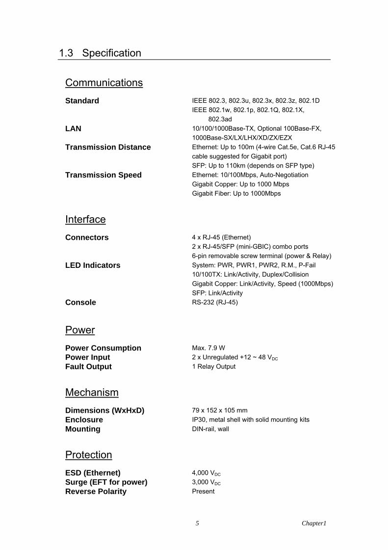
Communications
Standard IEEE 802.3, 802.3u, 802.3x, 802.3z, 802.1D IEEE 802.1w, 802.1p, 802.1Q, 802.1X, 802.3ad LAN 10/100/1000Base-TX, Optional 100Base-FX, 1000Base-SX/LX/LHX/XD/ZX/EZX Transmission Distance Ethernet: Up to 100m (4-wire Cat.5e, Cat.6 RJ-45 cable suggested for Gigabit port) SFP: Up to 110km (depends on SFP type) Transmission Speed Ethernet: 10/100Mbps, Auto-Negotiation Gigabit Copper: Up to 1000 Mbps Gigabit Fiber: Up to 1000Mbps
Interface
Connectors 4 x RJ-45 (Ethernet) 2 x RJ-45/SFP (mini-GBIC) combo ports 6-pin removable screw terminal (power & Relay) LED Indicators System: PWR, PWR1, PWR2, R.M., P-Fail 10/100TX: Link/Activity, Duplex/Collision Gigabit Copper: Link/Activity, Speed (1000Mbps) SFP: Link/Activity Console RS-232 (RJ-45)
Power
Power Consumption Max. 7.9 W Power Input 2 x Unregulated +12 ~ 48 VDC Fault Output 1 Relay Output
Mechanism
Dimensions (WxHxD) 79 x 152 x 105 mm Enclosure IP30, metal shell with solid mounting kits Mounting DIN-rail, wall
Protection
ESD (Ethernet) 4,000 VDC Surge (EFT for power) 3,000 VDC Reverse Polarity Present

EKI-7654C_Manual_2ed 6
Overload 1.6A@12VDC (Re-settable Fuse)
Environment
Operating Temperature -10 ~ 60oC (14 ~ 140oF) Wide temp. model: -40 ~ 75oC (-40 ~ 167oF) Operating Humidity 5 ~ 95% (non-condensing) Storage Temperature -40 ~ 85oC (-40 ~ 185oF) Storage Humidity 0 ~ 95% (non-condensing) MTBF 284,409 hours
Certifications
Safety UL, 60950-1, CAN/CSA-C22.2 No.60950 EMC EU: EN55011, EN61000-6-4 EN55022, Class A, EN61000-3-2/3 EN55024 IEC61000-4-2/3/4/5/6/8 EN61000-6-2 Freefall IEC60068-2-32 Shock IEC60068-2-27 Vibration IEC60068-2-6

7 Chapter1
1.4 Packing List
• 1 x EKI-7654C Industrial Managed Gigabit Ethernet Switch • 1 x eAutomation Industrial Communication CD-ROM with software, and User manual • 2 x Wall Mounting Bracket and Screws • 1 x DIN-rail Mounting Bracket and Screws • 1 x 8-pin RJ-45 to RS-232 serial cable • 1 x DC Jack Cable φ2.0/150mm • 1 x EKI-7654C Startup Manual
1.5 Safety Precaution Attention IF DC voltage is supplied by an external circuit, please use a protection device
on the power supply input.

EKI-7654C_Manual_2ed 8

9 Chapter2
Installation Sections include:
LED Indicators
Dimensions
Mounting
Network Connection
Connection to a Fiber Optic Network
Power Connection
CH
APT
ER

EKI-7654C_Manual_2ed 10
Chapter 2 Installation
In this chapter, you will be given an overview of the EKI-7654C hardware installation procedures.
2.1 LED Indicators
There are few LEDs display the power status and network status located on the front panel of EKI-7654C, each of them has its own specific meaning shown as below.
Table 2.1: EKI-7654C LED Definition
LED Color Description
On System power on PWR Green
Off No power input
On The industrial switch is the master of the X-ring group R.M. Green
Off The industrial switch is not the master of the X-ring group
On Power input 1 is active PWR1 Green
Off Power input 1 is inactive
On Power input 2 is active PWR2 Green
Off Power input 2 is inactive
On Power input 1 or 2 is inactive or port link down (depends on Fault Relay Alarm configuration) P-Fail Red
Off Power input 1 and 2 are both active, or no power input
On SFP port is linking
Flashing Data is transmitting or receiving Link/Active (for G5, G6 SFP) Green
Off Not connected to network
On The port is operating at speed of 1000M Green (Upper LED)
Off The port is disconnected or not operating at speed of 1000M
On Connected to network
Flashing Networking is active
G5, G6 (RJ-45)
Green (Lower LED)
Off Not connected to network
On Connected to network
Flashing Networking is active Link/Active (1~4) Green
Off Not connected to network
On Ethernet port full duplex
Flashing Collision of packets occurs Duplex/Collision (1~4) Orange
Off Ethernet port half duplex or not connected to network
11 Chapter2
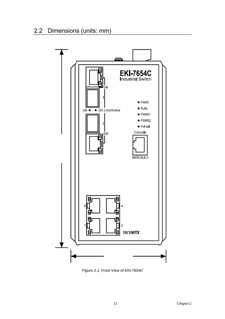
2.2 Dimensions (units: mm)
Figure 2.1: Front View of EKI-7654C
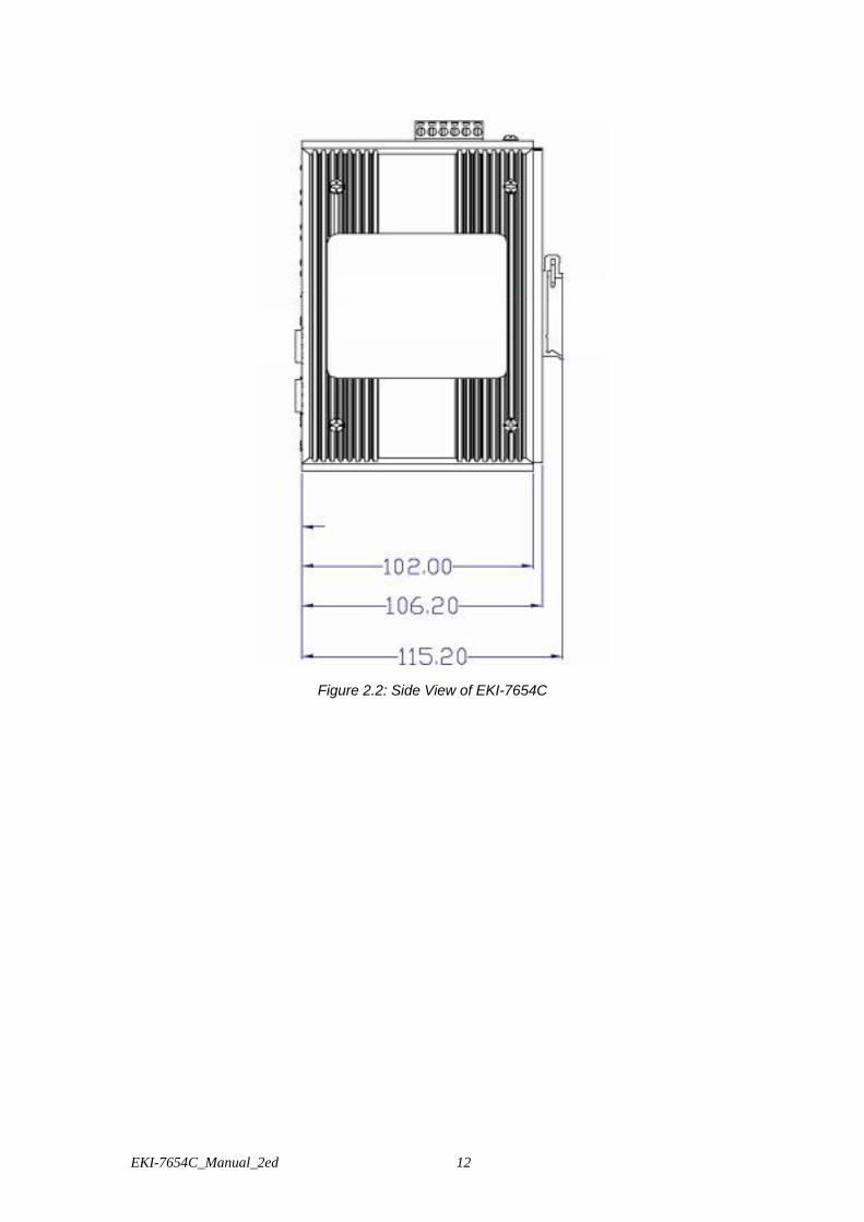
EKI-7654C_Manual_2ed 12
Figure 2.2: Side View of EKI-7654C
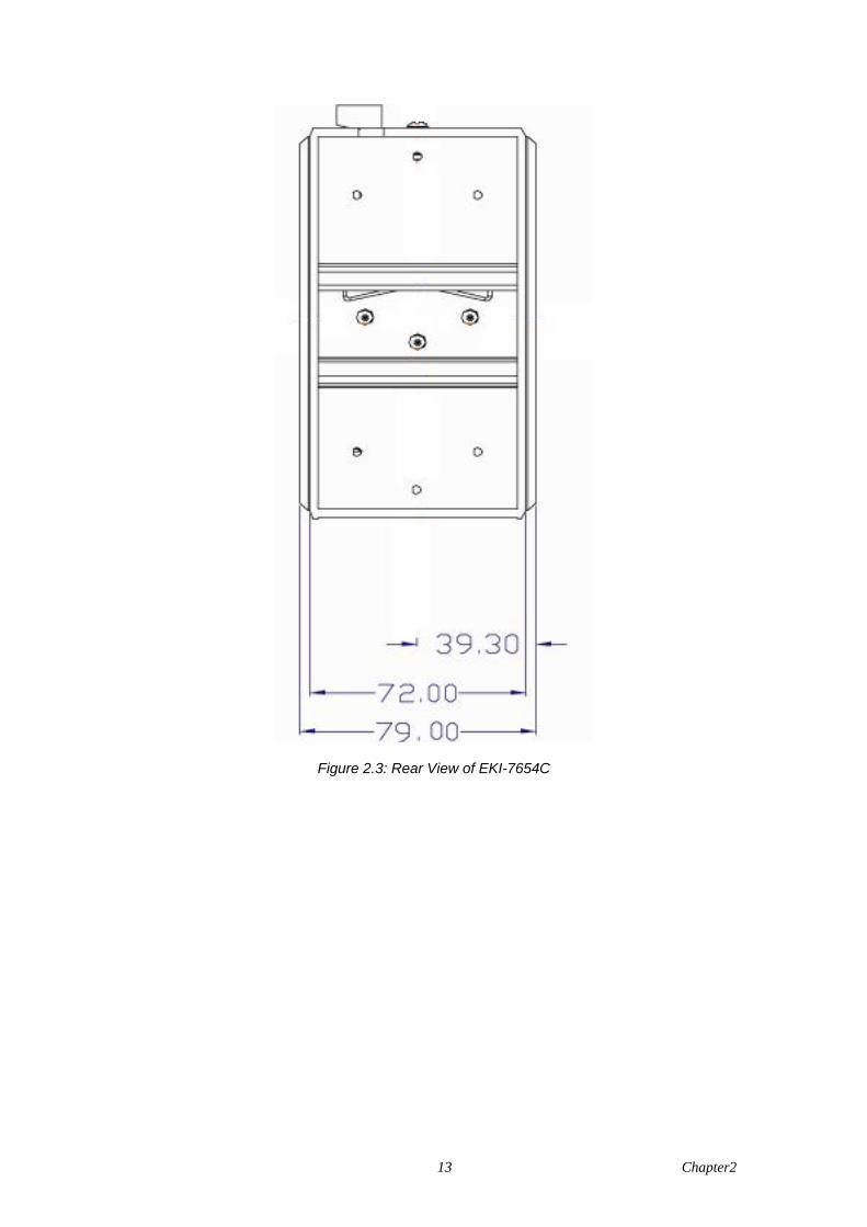
13 Chapter2
Figure 2.3: Rear View of EKI-7654C
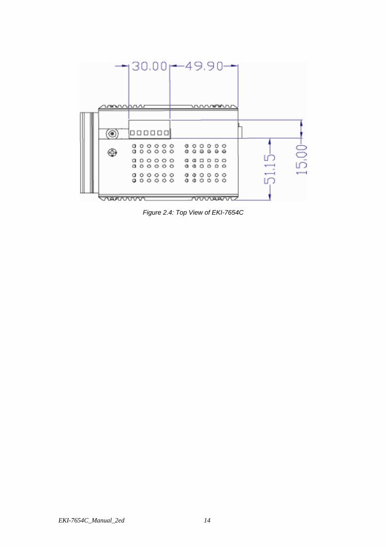
EKI-7654C_Manual_2ed 14
Figure 2.4: Top View of EKI-7654C

15 Chapter2
2.3 Mounting
The EKI-7654C supports two mounting methods: DIN-rail & Wall. 2.3.1 Wall mounting
EKI-7654C can be wall-mounted by using the included mounting kit. Then, hang on the EKI-7654C to the nails on the wall. First, use the screws included in the package to combine the EKI-7654C and metal mounting kit. And then you can install the device firmly via the components, please see Figure 2.5 as below.
Figure 2.5: Combine the Metal Mounting Kit (units: mm)

EKI-7654C_Manual_2ed 16
2.3.2 DIN-rail Mounting You can also mount EKI-7654C on a standard DIN-rail by steps below. The DIN-rail kit is screwed on the industrial switch when out of factory. If the DIN-rail kit is not screwed on the industrial switch, please screw the DIN-rail kit on the switch first. First, hang the EKI-7654C to the DIN-rail with angle of inclination. See Figure 2.6.
Figure 2.6: Installation to DIN-rail Step 1

17 Chapter2
Then, let the device down straight to slide over the rail smoothly. See Figure 2.7.
Figure 2.7: Installation to DIN-rail Step 2

EKI-7654C_Manual_2ed 18
2.4 Network Connection
The EKI-7654C has 8 x RJ-45 ports that support connection to 10 Mbps Ethernet, or 100 Mbps Fast Ethernet, and half or full duplex operation. EKI-7654C can be connected to other hubs or switches via a twisted-pair straight-through or crossover cable up to 100m long. The connection can be made from any TX port of the EKI-7654C (MDI-X) to another hub or switch either MDI-X or uplink MDI port. The EKI-7654C supports auto-crossover to make networking more easy and flexible. You can connect any RJ-45 (MDI-X) station port on the switch to any device such as a switch, bridge or router.
2.5 Connection to a Fiber Optic Network
EKI-7654C has two SFP slots for connecting to the network segment with single or multi-mode fiber. You can choose appropriate mini-GBIC module to plug into the slot. Make sure the module is aligned correctly and then slide the module into the SFP slot until a click is heard. You can use proper multi-mode or single-mode fiber according to the used SFP module. With fiber optic, it transmits speed up to 1000 Mbps and you can prevent noise interference from the system and transmission distance up to 110 km, depending on the mini-GBIC module. The small form-factor pluggable (SFP) is a compact optical transceiver used in optical communications for both telecommunication and data communications applications.
Note The SFP/Copper Combo port can’t be both used at the same time. The SFP port has the
higher priority than copper port; if you insert the 1000M SFP transceiver (which is connected to the remote device) into the SFP port, the connection of the accompanying copper port will link down. If you insert the 100M SFP transceiver into the SFP port even without a fiber connection to the remote, the connection of the accompanying copper port will link down immediately.
To connect the transceiver and LC cable, please follow the steps shown below:
First, insert the transceiver into the SFP module. Notice that the triangle mark is the bottom of the module.
Figure 2.8: Transceiver to the SFP module

19 Chapter2
Figure 2.9: Transceiver Inserted
Second, insert the fiber cable of LC connector into the transceiver.
Figure 2.10: LC connector to the transceiver

EKI-7654C_Manual_2ed 20
To remove the LC connector from the transceiver, please follow the steps shown below: First, press the upper side of the LC connector to release from the transceiver and pull it out.
Figure 2.11: Remove LC connector
Second, push down the metal loop and pull the transceiver out by the plastic handle.
Figure 2.12: Pull out from the transceiver

21 Chapter2
2.6 Power Connection
The EKI-7654C supports dual +12 ~ 48 VDC power inputs and power-fail relay output.
Figure 2.13: Pin Assignment of the Power Connector
You can connect an alarm indicator, buzzer or other signaling equipment through the relay output. The relay opens if power input 1, 2 fails or port link down/break (″Open″ means if you connect relay output with an LED, the light would be off).

EKI-7654C_Manual_2ed 22
23 Chapter3
Configuration Sections include:
RS-232 Console
Web Browser
Mounting
Self Diagnosis
CH
APT
ER
EKI-7654C_Manual_2ed 24
Chapter 3 Configuration The EKI-7654C can be configured in two ways: via RS-232 Console or a web browser.
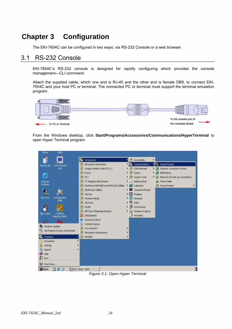
3.1 RS-232 Console EKI-7654C’s RS-232 console is designed for rapidly configuring which provides the console management—CLI command. Attach the supplied cable, which one end is RJ-45 and the other end is female DB9, to connect EKI-7654C and your host PC or terminal. The connected PC or terminal must support the terminal emulation program.
From the Windows desktop, click Start/Programs/Accessories/Communications/HyperTerminal to open Hyper Terminal program.
Figure 3.1: Open Hyper Terminal
25 Chapter3
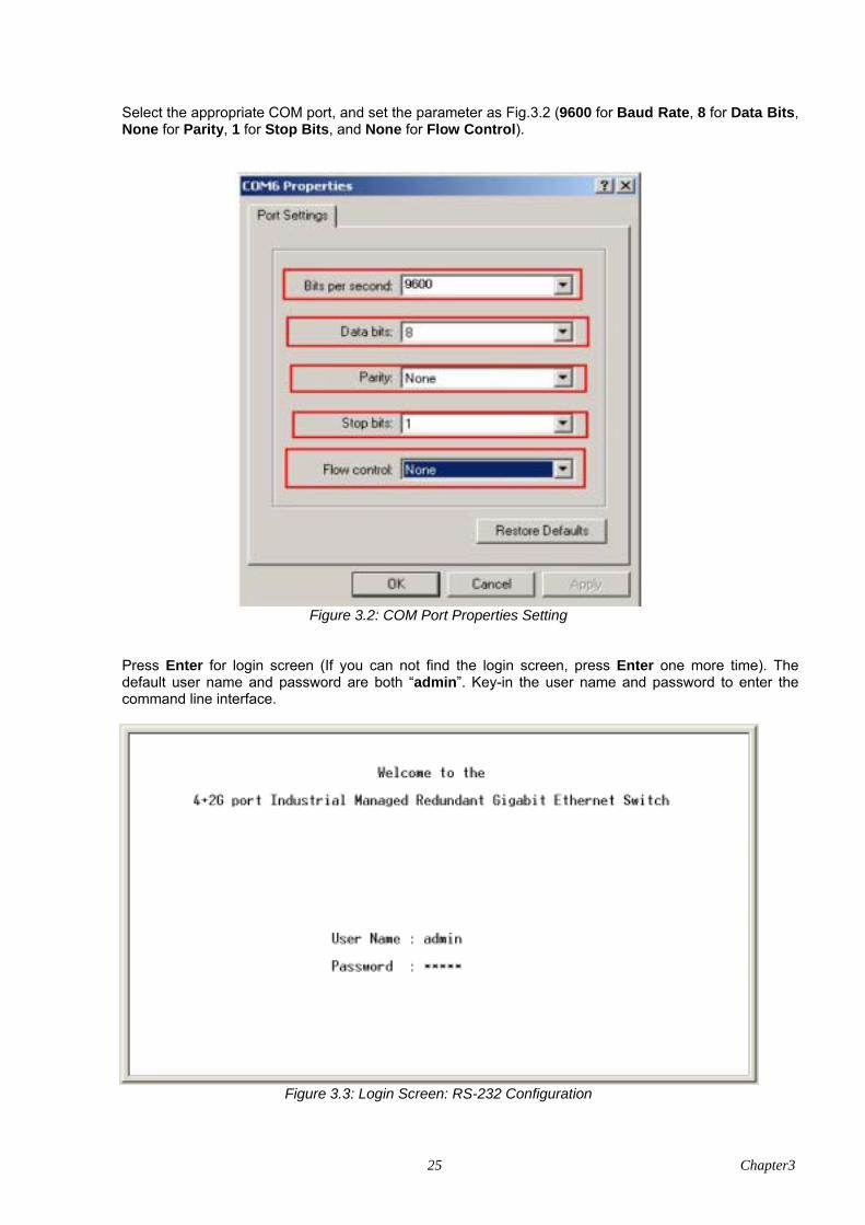
Select the appropriate COM port, and set the parameter as Fig.3.2 (9600 for Baud Rate, 8 for Data Bits, None for Parity, 1 for Stop Bits, and None for Flow Control).
Figure 3.2: COM Port Properties Setting
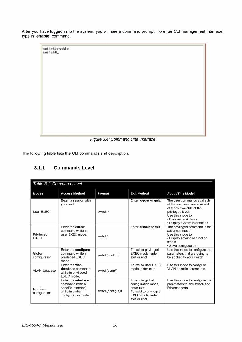
Press Enter for login screen (If you can not find the login screen, press Enter one more time). The default user name and password are both “admin”. Key-in the user name and password to enter the command line interface.
Figure 3.3: Login Screen: RS-232 Configuration
EKI-7654C_Manual_2ed 26
After you have logged in to the system, you will see a command prompt. To enter CLI management interface, type in “enable” command.
Figure 3.4: Command Line Interface
The following table lists the CLI commands and description.
3.1.1 Commands Level
Table 3.1: Command Level
Modes Access Method Prompt Exit Method About This Model
User EXEC
Begin a session with your switch.
switch>
Enter logout or quit. The user commands available at the user level are a subset of those available at the privileged level. Use this mode to • Perform basic tests. • Display system information.
Privileged EXEC
Enter the enable command while in user EXEC mode. switch#
Enter disable to exit. The privileged command is the advanced mode Use this mode to • Display advanced function status • Save configuration
Global configuration
Enter the configure command while in privileged EXEC mode.
switch(config)#
To exit to privileged EXEC mode, enter exit or end
Use this mode to configure theparameters that are going to be applied to your switch
VLAN database
Enter the vlan database command while in privileged EXEC mode.
switch(vlan)# To exit to user EXEC mode, enter exit.
Use this mode to configure VLAN-specific parameters.
Interface configuration
Enter the interface command (with a specific interface) while in global configuration mode
switch(config-if)#
To exit to global configuration mode, enter exit. To exist to privileged EXEC mode, enter exit or end.
Use this mode to configure the parameters for the switch and Ethernet ports.

27 Chapter3
3.1.2 Commands Set List
Table 3.2: Commands Set List
Command Code Word
User EXEC E
Privileged EXEC P
Global configuration G
VLAN database V
Interface configuration I
3.1.3 System Commands Set
Table 3.3: System Commands Set
Netstar Commands Level Description Example
show config E Show switch configuration switch>show config show terminal P Show console information switch#show terminal write memory P Save user configuration into
permanent memory (flash rom) switch#write memory
system name [System Name] G Configure system name switch(config)#system name xxx
system location [System Location] G Set switch system location string switch(config)#system location xxx
system description [System Description] G Set switch system description string switch(config)#system description xxx
system contact [System Contact] G Set switch system contact window
string switch(config)#system contact xxx
show system-info E Show system information switch>show system-info ip address [Ip-address] [Subnet-mask] [Gateway]
G Configure the IP address of switch switch(config)#ip address 192.168.1.1
255.255.255.0 192.168.1.254
ip dhcp G Enable DHCP client function of
switch switch(config)#ip dhcp
show ip P Show IP information of switch switch#show ip no ip dhcp G Disable DHCP client function of
switch switch(config)#no ip dhcp
reload G Halt and perform a cold restart switch(config)#reload default G Restore to default switch(config)#default admin username [Username] G Changes a login username.
(maximum 10 words) switch(config)#admin username xxxxxx
admin password [Password] G Specifies a password
(maximum 10 words) switch(config)#admin password xxxxxx
show admin P Show administrator information switch#show admin dhcpserver enable G Enable DHCP Server switch(config)#dhcpserver enable
Dhcpserver disable G Disable DHCP Server switch(config)#no dhcpserver
dhcpserver lowip [Low IP] G
Configure low IP address for IP pool switch(config)#dhcpserver lowip 192.168.1.100
dhcpserver highip [High IP] G
Configure high IP address for IP pool
switch(config)#dhcpserver highip 192.168.1.200
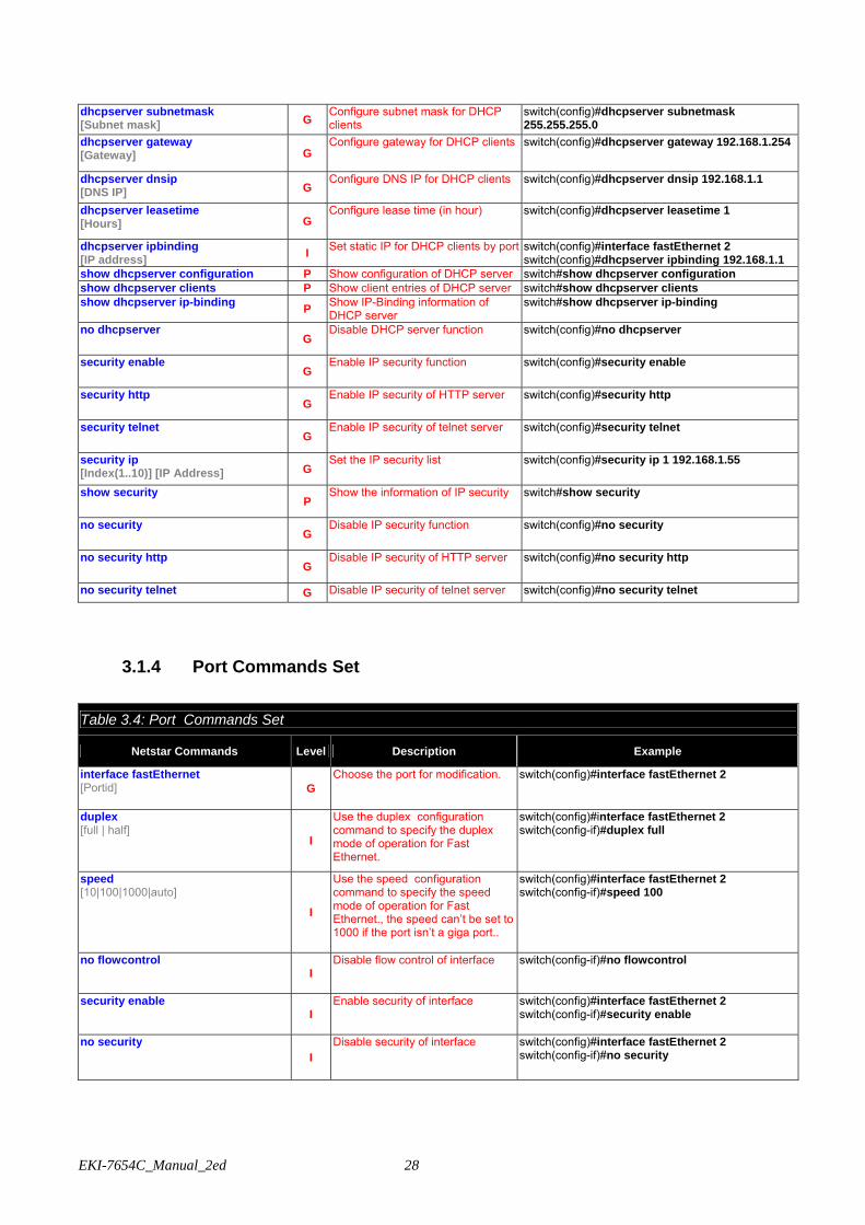
EKI-7654C_Manual_2ed 28
dhcpserver subnetmask [Subnet mask] G
Configure subnet mask for DHCP clients
switch(config)#dhcpserver subnetmask 255.255.255.0
dhcpserver gateway [Gateway] G
Configure gateway for DHCP clients switch(config)#dhcpserver gateway 192.168.1.254
dhcpserver dnsip [DNS IP] G
Configure DNS IP for DHCP clients switch(config)#dhcpserver dnsip 192.168.1.1
dhcpserver leasetime [Hours] G
Configure lease time (in hour) switch(config)#dhcpserver leasetime 1
dhcpserver ipbinding [IP address] I Set static IP for DHCP clients by port switch(config)#interface fastEthernet 2
switch(config)#dhcpserver ipbinding 192.168.1.1 show dhcpserver configuration P Show configuration of DHCP server switch#show dhcpserver configuration show dhcpserver clients P Show client entries of DHCP server switch#show dhcpserver clients show dhcpserver ip-binding P Show IP-Binding information of
DHCP server switch#show dhcpserver ip-binding
no dhcpserver G
Disable DHCP server function switch(config)#no dhcpserver
security enable G
Enable IP security function switch(config)#security enable
security http G
Enable IP security of HTTP server switch(config)#security http
security telnet G
Enable IP security of telnet server switch(config)#security telnet
security ip [Index(1..10)] [IP Address] G
Set the IP security list switch(config)#security ip 1 192.168.1.55
show security P
Show the information of IP security switch#show security
no security G
Disable IP security function switch(config)#no security
no security http G
Disable IP security of HTTP server switch(config)#no security http
no security telnet G Disable IP security of telnet server switch(config)#no security telnet
3.1.4 Port Commands Set
Table 3.4: Port Commands Set
Netstar Commands Level Description Example
interface fastEthernet [Portid] G
Choose the port for modification. switch(config)#interface fastEthernet 2
duplex [full | half] I
Use the duplex configuration command to specify the duplex mode of operation for Fast Ethernet.
switch(config)#interface fastEthernet 2 switch(config-if)#duplex full
speed [10|100|1000|auto]
I
Use the speed configuration command to specify the speed mode of operation for Fast Ethernet., the speed can’t be set to 1000 if the port isn’t a giga port..
switch(config)#interface fastEthernet 2 switch(config-if)#speed 100
no flowcontrol I
Disable flow control of interface switch(config-if)#no flowcontrol
security enable I
Enable security of interface switch(config)#interface fastEthernet 2 switch(config-if)#security enable
no security I
Disable security of interface switch(config)#interface fastEthernet 2 switch(config-if)#no security

29 Chapter3
bandwidth type all I
Set interface ingress limit frame type to “accept all frame”
switch(config)#interface fastEthernet 2 switch(config-if)#bandwidth type all
bandwidth type broadcast-multicast-flooded-unicast I
Set interface ingress limit frame type to “accept broadcast, multicast, and flooded unicast frame”
switch(config)#interface fastEthernet 2 switch(config-if)#bandwidth type broadcast-multicast-flooded-unicast
bandwidth type broadcast-multicast I
Set interface ingress limit frame type to “accept broadcast and multicast frame”
switch(config)#interface fastEthernet 2 switch(config-if)#bandwidth type broadcast-multicast
bandwidth type broadcast-only I
Set interface ingress limit frame type to “only accept broadcast frame”
switch(config)#interface fastEthernet 2 switch(config-if)#bandwidth type broadcast-only
bandwidth in [Value]
I
Set interface input bandwidth. Rate Range is from 100 kbps to 102400 kbps or to 256000 kbps for giga ports, and zero means no limit.
switch(config)#interface fastEthernet 2 switch(config-if)#bandwidth in 100
bandwidth out [Value]
Set interface output bandwidth. Rate Range is from 100 kbps to 102400 kbps or to 256000 kbps for giga ports, and zero means no limit.
switch(config)#interface fastEthernet 2 switch(config-if)#bandwidth out 100
show bandwidth I
Show interfaces bandwidth control switch(config)#interface fastEthernet 2 switch(config-if)#show bandwidth
state [Enable | Disable]
I
Use the state interface configuration command to specify the state mode of operation for Ethernet ports. Use the disable form of this command to disable the port.
switch(config)#interface fastEthernet 2 switch(config-if)#state Disable
show interface configuration I show interface configuration status switch(config)#interface fastEthernet 2 switch(config-if)#show interface configuration
show interface status I show interface actual status switch(config)#interface fastEthernet 2 switch(config-if)#show interface status
show interface accounting I
show interface statistic counter switch(config)#interface fastEthernet 2 switch(config-if)#show interface accounting
no accounting I
Clear interface accounting information
switch(config)#interface fastEthernet 2 switch(config-if)#no accounting
3.1.5 Trunk Commands Set Table 3.5: Trunk Commands Set
Netstar Commands Level Description Example
aggregator priority [1~65535] G Set port group system priority switch(config)#aggregator priority 22
aggregator activityport [Group ID] [Port Numbers]
G Set activity port switch(config)#aggregator activityport 2
aggregator group [GroupID] [Port-list] lacp workp [Workport]
G
Assign a trunk group with LACP active. [GroupID] :1~3 [Port-list]:Member port list, This parameter could be a port range(ex.1-4) or a port list separate by a comma(ex.2, 3, 6) [Workport]: The amount of work ports, this value could not be less than zero or be large than the amount of member ports.
switch(config)#aggregator group 1 1-4 lacp workp 2 or switch(config)#aggregator group 2 1,4,3 lacp workp 3

EKI-7654C_Manual_2ed 30
aggregator group [GroupID] [Port-list] nolacp G
Assign a static trunk group. [GroupID] :1~3 [Port-list]:Member port list, This parameter could be a port range(ex.1-4) or a port list separate by a comma(ex.2, 3, 6)
switch(config)#aggregator group 1 2-4 nolacp or switch(config)#aggregator group 1 3,1,2 nolacp
show aggregator
P
Show the information of trunk group switch#show aggregator 1 or switch#show aggregator 2 or switch#show aggregator 3
no aggregator lacp [GroupID]
G
Disable the LACP function of trunk group
switch(config)#no aggreator lacp 1
no aggregator group [GroupID] G
Remove a trunk group switch(config)#no aggreator group 2
3.1.6 VLAN Commands Set Table 3.6: VLAN Commands Set
Netstar Commands Level Description Example
vlan database P Enter VLAN configure mode switch#vlan database Vlanmode [portbase| 802.1q | gvrp] V
To set switch VLAN mode. switch(vlan)#vlanmode portbase or switch(vlan)#vlanmode 802.1q or switch(vlan)#vlanmode gvrp
no vlan V No VLAN Switch(vlan)#no vlan
Ported based VLAN configuration
vlan port-based grpname [Group Name] grpid [GroupID] port [PortNumbers]
V
Add new port based VALN switch(vlan)#vlan port-based grpname test grpid 2 port 2-4 or switch(vlan)#vlan port-based grpname test grpid 2 port 2,3,4
show vlan [GroupID] or show vlan V
Show VLAN information switch(vlan)#show vlan 23
no vlan group [GroupID] V Delete port base group ID switch(vlan)#no vlan group 2
IEEE 802.1Q VLAN
vlan 8021q name [GroupName] vid [VID]
V
Change the name of VLAN group, if the group didn’t exist, this command can’t be applied.
switch(vlan)#vlan 8021q name test vid 22
vlan 8021q port [PortNumber] access-link untag [UntaggedVID]
V Assign a access link for VLAN by port, if the port belong to a trunk group, this command can’t be applied.
switch(vlan)#vlan 8021q port 3 access-link untag 33
vlan 8021q port [PortNumber] trunk-link tag [TaggedVID List]
V Assign a trunk link for VLAN by port, if the port belong to a trunk group, this command can’t be applied.
switch(vlan)#vlan 8021q port 3 trunk-link tag 2,3,6,99 or switch(vlan)#vlan 8021q port 3 trunk-link tag 3-20
vlan 8021q port [PortNumber] hybrid-link untag [UntaggedVID] tag [TaggedVID List]
V
Assign a hybrid link for VLAN by port, if the port belong to a trunk group, this command can’t be applied.
switch(vlan)#vlan 8021q port 3 hybrid-link untag 4 tag 3,6,8 or switch(vlan)#vlan 8021q port 3 hybrid-link untag 5 tag 6-8
31 Chapter3
vlan 8021q trunk [PortNumber] access-link untag [UntaggedVID]
V Assign a access link for VLAN by trunk group
switch(vlan)#vlan 8021q trunk 3 access-link untag 33
vlan 8021q trunk [PortNumber] trunk-link tag [TaggedVID List]
V
Assign a trunk link for VLAN by trunk group
switch(vlan)#vlan 8021q trunk 3 trunk-link tag 2,3,6,99 or switch(vlan)#vlan 8021q trunk 3 trunk-link tag 3-20
vlan 8021q trunk [PortNumber] hybrid-link untag [UntaggedVID] tag [TaggedVID List]
V
Assign a hybrid link for VLAN by trunk group
switch(vlan)#vlan 8021q trunk 3 hybrid-link untag 4 tag 3,6,8 or switch(vlan)#vlan 8021q trunk 3 hybrid-link untag 5 tag 6-8
show vlan [GroupID] or show vlan V
Show VLAN information switch(vlan)#show vlan 23
no vlan group [GroupID] V Delete port base group ID switch(vlan)#no vlan group 2
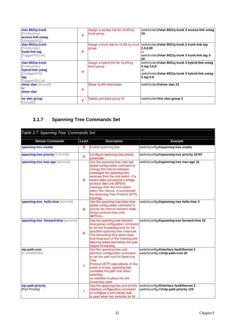
3.1.7 Spanning Tree Commands Set Table 3.7: Spanning Tree Commands Set
Netstar Commands Level Description Example
spanning-tree enable G
Enable spanning tree switch(config)#spanning-tree enable
spanning-tree priority [0~61440] G Configure spanning tree priority parameter
switch(config)#spanning-tree priority 32767
spanning-tree max-age [seconds]
G
Use the spanning-tree max-age global configuration command to change the interval between messages the spanning tree receives from the root switch. If a switch does not receive a bridge protocol data unit (BPDU) message from the root switch within this interval, it recomputed the Spanning Tree Protocol (STP) topology.
switch(config)#spanning-tree max-age 15
spanning-tree hello-time [seconds]
G
Use the spanning-tree hello-time global configuration command to specify the interval between hello bridge protocol data units (BPDUs).
switch(config)#spanning-tree hello-time 3
spanning-tree forward-time [seconds]
G
Use the spanning-tree forward-time global configuration command to set the forwarding-time for the specified spanning-tree instances. The forwarding time determines how long each of the listening and learning states last before the port begins forwarding.
switch(config)#spanning-tree forward-time 20
stp-path-cost [1~200000000]
I
Use the spanning-tree cost interface configuration command to set the path cost for Spanning Tree Protocol (STP) calculations. In the event of a loop, spanning tree considers the path cost when selecting an interface to place into the forwarding state.
switch(config)#interface fastEthernet 2 switch(config-if)#stp-path-cost 20
stp-path-priority [Port Priority] I
Use the spanning-tree port-priority interface configuration command to configure a port priority that is used when two switches tie for
switch(config)#interface fastEthernet 2 switch(config-if)#stp-path-priority 128
EKI-7654C_Manual_2ed 32
position as the root switch. stp-admin-p2p [Auto|True|False] I Admin P2P of STP priority on this
interface. switch(config)#interface fastEthernet 2 switch(config-if)#stp-admin-p2p Auto
stp-admin-edge [True|False] I Admin Edge of STP priority on this
interface. switch(config)#interface fastEthernet 2 switch(config-if)#stp-admin-edge True
stp-admin-non-stp [True|False] I Admin NonSTP of STP priority on
this interface. switch(config)#interface fastEthernet 2 switch(config-if)#stp-admin-non-stp False
show spanning-tree E Displays a summary of the
spanning-tree states. switch>show spanning-tree
no spanning-tree G Disable spanning-tree. switch(config)#no spanning-tree
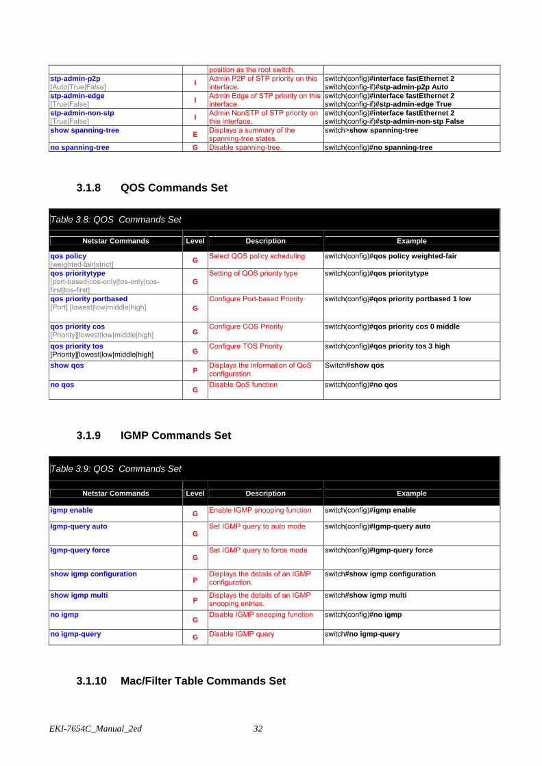
3.1.8 QOS Commands Set Table 3.8: QOS Commands Set
Netstar Commands Level Description Example
qos policy [weighted-fair|strict] G Select QOS policy scheduling switch(config)#qos policy weighted-fair
qos prioritytype [port-based|cos-only|tos-only|cos-first|tos-first]
G Setting of QOS priority type switch(config)#qos prioritytype
qos priority portbased [Port] [lowest|low|middle|high] G
Configure Port-based Priority switch(config)#qos priority portbased 1 low
qos priority cos [Priority][lowest|low|middle|high] G
Configure COS Priority switch(config)#qos priority cos 0 middle
qos priority tos [Priority][lowest|low|middle|high] G
Configure TOS Priority switch(config)#qos priority tos 3 high
show qos P
Displays the information of QoS configuration
Switch#show qos
no qos G
Disable QoS function switch(config)#no qos
3.1.9 IGMP Commands Set Table 3.9: QOS Commands Set
Netstar Commands Level Description Example
igmp enable G Enable IGMP snooping function switch(config)#igmp enable
Igmp-query auto G
Set IGMP query to auto mode switch(config)#Igmp-query auto
Igmp-query force G
Set IGMP query to force mode switch(config)#Igmp-query force
show igmp configuration P
Displays the details of an IGMP configuration.
switch#show igmp configuration
show igmp multi P
Displays the details of an IGMP snooping entries.
switch#show igmp multi
no igmp G
Disable IGMP snooping function switch(config)#no igmp
no igmp-query G Disable IGMP query switch#no igmp-query
3.1.10 Mac/Filter Table Commands Set
33 Chapter3
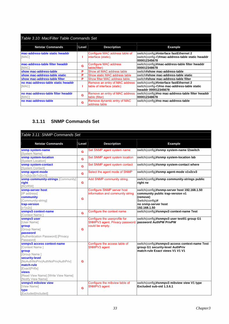
Table 3.10: Mac/Filter Table Commands Set
Netstar Commands Level Description Example
mac-address-table static hwaddr [MAC] I
Configure MAC address table of interface (static).
switch(config)#interface fastEthernet 2 switch(config-if)#mac-address-table static hwaddr 000012345678
mac-address-table filter hwaddr [MAC] G Configure MAC address
table(filter) switch(config)#mac-address-table filter hwaddr 000012348678
show mac-address-table P Show all MAC address table switch#show mac-address-table show mac-address-table static P Show static MAC address table switch#show mac-address-table static show mac-address-table filter P Show filter MAC address table. switch#show mac-address-table filter no mac-address-table static hwaddr [MAC] I
Remove an entry of MAC address table of interface (static)
switch(config)#interface fastEthernet 2 switch(config-if)#no mac-address-table static hwaddr 000012345678
no mac-address-table filter hwaddr [MAC] G Remove an entry of MAC address
table (filter) switch(config)#no mac-address-table filter hwaddr 000012348678
no mac-address-table G Remove dynamic entry of MAC address table
switch(config)#no mac-address-table
3.1.11 SNMP Commands Set Table 3.11: SNMP Commands Set
Netstar Commands Level Description Example
snmp system-name [System Name] G Set SNMP agent system name switch(config)#snmp system-name l2switch
snmp system-location [System Location] G Set SNMP agent system location switch(config)#snmp system-location lab
snmp system-contact [System Contact] G Set SNMP agent system contact switch(config)#snmp system-contact where
snmp agent-mode [v1v2c|v3|v1v2cv3] G Select the agent mode of SNMP switch(config)#snmp agent-mode v1v2cv3
snmp community-strings [Community] right [RO/RW]
G Add SNMP community string. switch(config)#snmp community-strings public
right rw
snmp-server host [IP address] community [Community-string] trap-version [v1|v2c]
G
Configure SNMP server host information and community string
switch(config)#snmp-server host 192.168.1.50 community public trap-version v1 (remove) Switch(config)# no snmp-server host 192.168.1.50
snmpv3 context-name [Context Name ] G Configure the context name switch(config)#snmpv3 context-name Test
snmpv3 user [User Name] group [Group Name] password [Authentication Password] [Privacy Password]
G
Configure the userprofile for SNMPV3 agent. Privacy password could be empty.
switch(config)#snmpv3 user test01 group G1 password AuthPW PrivPW
snmpv3 access context-name [Context Name ] group [Group Name ] security-level [NoAuthNoPriv|AuthNoPriv|AuthPriv] match-rule [Exact|Prifix] views [Read View Name] [Write View Name] [Notify View Name]
G
Configure the access table of SNMPV3 agent
switch(config)#snmpv3 access context-name Test group G1 security-level AuthPriv match-rule Exact views V1 V1 V1
snmpv3 mibview view [View Name] type [Excluded|Included]
G Configure the mibview table of SNMPV3 agent
switch(config)#snmpv3 mibview view V1 type Excluded sub-oid 1.3.6.1

EKI-7654C_Manual_2ed 34
sub-oid [OID] show snmp P Show SNMP configuration switch#show snmp no snmp community-strings [Community] G Remove the specified community. switch(config)#no snmp community-strings public
no snmp-server host [Host-address] G Remove the SNMP server host. switch(config)#no snmp-server 192.168.1.50
no snmpv3 user [User Name] G Remove specified user of SNMPv3
agent. switch(config)#no snmpv3 user Test
no snmpv3 access context-name [Context Name ] group [Group Name ] security-level [NoAuthNoPriv|AuthNoPriv|AuthPriv] match-rule [Exact|Prifix] views [Read View Name] [Write View Name] [Notify View Name]
G
Remove specified access table of SNMPv3 agent.
switch(config)#no snmpv3 access context-name Test group G1 security-level AuthPr iv match-rule Exact views V1 V1 V1
no snmpv3 mibview view [View Name] type [Excluded|Included] sub-oid [OID]
G
Remove specified mibview table of SNMPV3 agent.
switch(config)#no snmpv3 mibview view V1 type Excluded sub-oid 1.3.6.1
3.1.12 Port Mirroring Commands Set Table 3.12: Port Mirroring Commands Set
Netstar Commands Level Description Example
monitor rx G Set RX destination port of monitor function
switch(config)#monitor rx
monitor tx G
Set TX destination port of monitor function
switch(config)#monitor tx
show monitor P Show port monitor information switch#show monitor
monitor [RX|TX|Both] I
Configure source port of monitor function
switch(config)#interface fastEthernet 2 switch(config-if)#monitor RX
show monitor I
Show port monitor information switch(config)#interface fastEthernet 2 switch(config-if)#show monitor
no monitor I
Disable source port of monitor function
switch(config)#interface fastEthernet 2 switch(config-if)#no monitor
3.1.13 802.1x Commands Set Table 3.13: 802.1x Commands Set
Netstar Commands Level Description Example
8021x enable G
Use the 802.1x global configuration command to enable 802.1x protocols.
switch(config)# 8021x enable
8021x system radiusip [IP address]
G Use the 802.1x system radius IP global configuration command to change the radius server IP.
switch(config)# 8021x system radiusip 192.168.1.1
8021x system serverport [port ID] G Use the 802.1x system server port
global configuration command to switch(config)# 8021x system serverport 1815
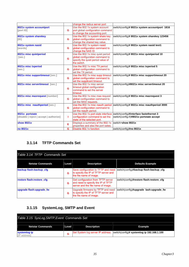
35 Chapter3
change the radius server port 8021x system accountport [port ID]
G Use the 802.1x system account port global configuration command to change the accounting port
switch(config)# 8021x system accountport 1816
8021x system sharekey [ID]
G Use the 802.1x system share key global configuration command to change the shared key value.
switch(config)# 8021x system sharekey 123456
8021x system nasid [words]
G Use the 802.1x system nasid global configuration command to change the NAS ID
switch(config)# 8021x system nasid test1
8021x misc quietperiod [sec.] G
Use the 802.1x misc quiet period global configuration command to specify the quiet period value of the switch.
switch(config)# 8021x misc quietperiod 10
8021x misc txperiod [sec.]
G Use the 802.1x misc TX period global configuration command to set the TX period.
switch(config)# 8021x misc txperiod 5
8021x misc supportimeout [sec.] G
Use the 802.1x misc supp timeout global configuration command to set the supplicant timeout.
switch(config)# 8021x misc supportimeout 20
8021x misc servertimeout [sec.] G
Use the 802.1x misc server timeout global configuration command to set the server timeout.
switch(config)#8021x misc servertimeout 20
8021x misc maxrequest [number] G
Use the 802.1x misc max request global configuration command to set the MAX requests.
switch(config)# 8021x misc maxrequest 3
8021x misc reauthperiod [sec.] G
Use the 802.1x misc reauth period global configuration command to set the reauth period.
switch(config)# 8021x misc reauthperiod 3000
8021x portstate [disable | reject | accept | authorize]
I Use the 802.1x port state interface configuration command to set the state of the selected port.
switch(config)#interface fastethernet 3 switch(config-if)#8021x portstate accept
show 8021x E Displays a summary of the 802.1x properties and also the port sates.
switch>show 8021x
no 8021x G Disable 802.1x function switch(config)#no 8021x
3.1.14 TFTP Commands Set Table 3.14: TFTP Commands Set
Netstar Commands Level Description Defaults Example
backup flash:backup_cfg G
Save configuration to TFTP and need to specify the IP of TFTP server and the file name of image.
switch(config)#backup flash:backup_cfg
restore flash:restore_cfg G
Get configuration from TFTP server and need to specify the IP of TFTP server and the file name of image.
switch(config)#restore flash:restore_cfg
upgrade flash:upgrade_fw G
Upgrade firmware by TFTP and need to specify the IP of TFTP server and the file name of image.
switch(config)#upgrade lash:upgrade_fw
3.1.15 SystemLog, SMTP and Event
Table 3.15: SysLog,SMTP,Event Commands Set
Netstar Commands Level Description Example
systemlog ip [IP address] G Set System log server IP address. switch(config)# systemlog ip 192.168.1.100
EKI-7654C_Manual_2ed 36
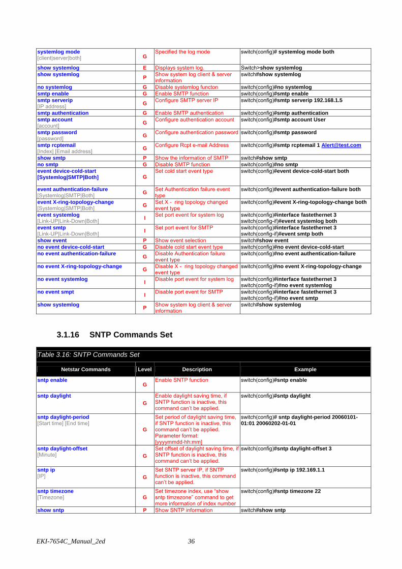
systemlog mode [client|server|both] G
Specified the log mode switch(config)# systemlog mode both
show systemlog E Displays system log. Switch>show systemlog show systemlog P Show system log client & server
information switch#show systemlog
no systemlog G Disable systemlog functon switch(config)#no systemlog smtp enable G Enable SMTP function switch(config)#smtp enable smtp serverip [IP address] G Configure SMTP server IP switch(config)#smtp serverip 192.168.1.5
smtp authentication G Enable SMTP authentication switch(config)#smtp authentication smtp account [account] G Configure authentication account switch(config)#smtp account User
smtp password [password] G Configure authentication password switch(config)#smtp password
smtp rcptemail [Index] [Email address] G Configure Rcpt e-mail Address switch(config)#smtp rcptemail 1 [email protected]
show smtp P Show the information of SMTP switch#show smtp no smtp G Disable SMTP function switch(config)#no smtp event device-cold-start [Systemlog|SMTP|Both] G
Set cold start event type switch(config)#event device-cold-start both
event authentication-failure [Systemlog|SMTP|Both] G Set Authentication failure event
type switch(config)#event authentication-failure both
event X-ring-topology-change [Systemlog|SMTP|Both] G Set X - ring topology changed
event type switch(config)#event X-ring-topology-change both
event systemlog [Link-UP|Link-Down|Both] I Set port event for system log switch(config)#interface fastethernet 3
switch(config-if)#event systemlog both event smtp [Link-UP|Link-Down|Both] I Set port event for SMTP switch(config)#interface fastethernet 3
switch(config-if)#event smtp both show event P Show event selection switch#show event no event device-cold-start G Disable cold start event type switch(config)#no event device-cold-start no event authentication-failure G Disable Authentication failure
event type switch(config)#no event authentication-failure
no event X-ring-topology-change G Disable X - ring topology changed event type
switch(config)#no event X-ring-topology-change
no event systemlog I Disable port event for system log switch(config)#interface fastethernet 3 switch(config-if)#no event systemlog
no event smpt I Disable port event for SMTP switch(config)#interface fastethernet 3 switch(config-if)#no event smtp
show systemlog P Show system log client & server information
switch#show systemlog
3.1.16 SNTP Commands Set
Table 3.16: SNTP Commands Set
Netstar Commands Level Description Example
sntp enable G
Enable SNTP function switch(config)#sntp enable
sntp daylight G
Enable daylight saving time, if SNTP function is inactive, this command can’t be applied.
switch(config)#sntp daylight
sntp daylight-period [Start time] [End time]
G
Set period of daylight saving time, if SNTP function is inactive, this command can’t be applied. Parameter format: [yyyymmdd-hh:mm]
switch(config)# sntp daylight-period 20060101-01:01 20060202-01-01
sntp daylight-offset [Minute] G
Set offset of daylight saving time, if SNTP function is inactive, this command can’t be applied.
switch(config)#sntp daylight-offset 3
sntp ip [IP] G
Set SNTP server IP, if SNTP function is inactive, this command can’t be applied.
switch(config)#sntp ip 192.169.1.1
sntp timezone [Timezone] G
Set timezone index, use “show sntp timzezone” command to get more information of index number
switch(config)#sntp timezone 22
show sntp P Show SNTP information switch#show sntp
37 Chapter3
show sntp timezone P
Show index number of time zone list
switch#show sntp timezone
no sntp G Disable SNTP function switch(config)#no sntp
no sntp daylight G Disable daylight saving time switch(config)#no sntp daylight
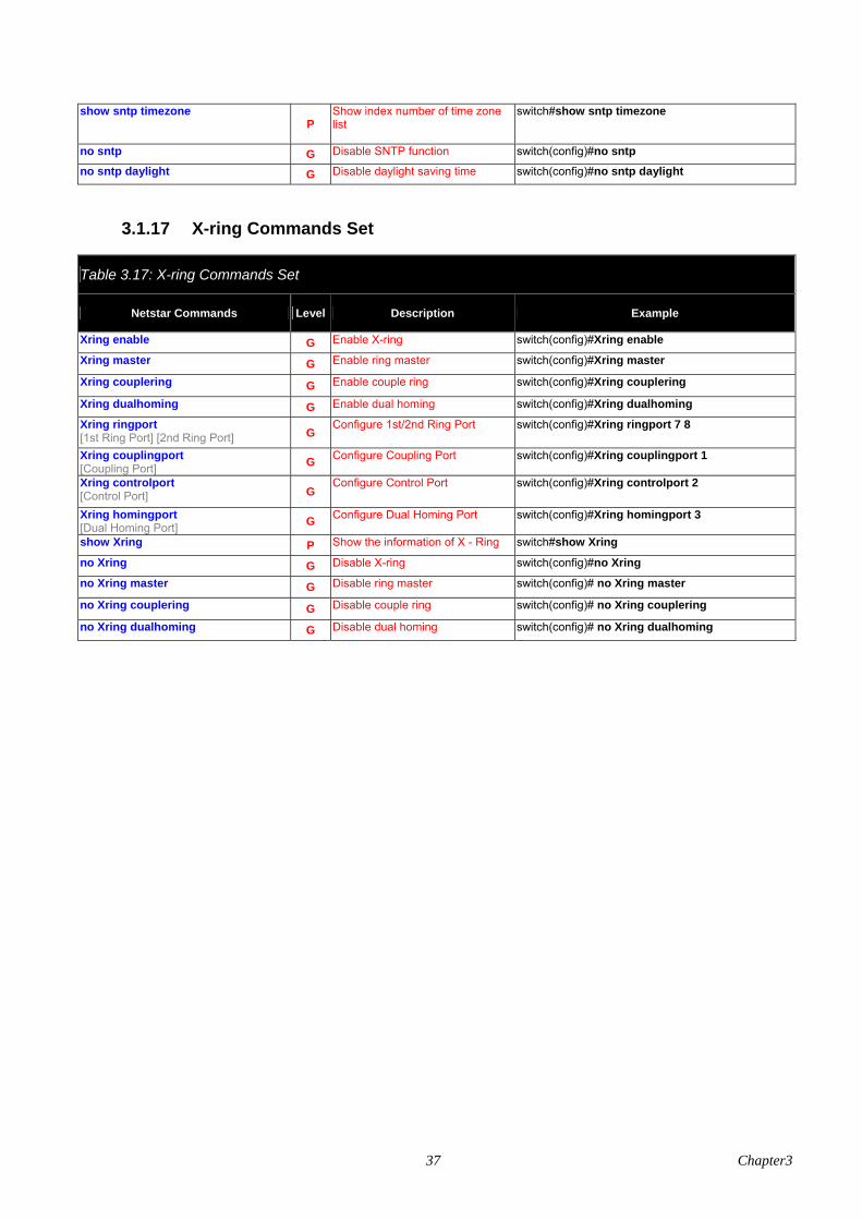
3.1.17 X-ring Commands Set
Table 3.17: X-ring Commands Set
Netstar Commands Level Description Example
Xring enable G Enable X-ring switch(config)#Xring enable
Xring master G Enable ring master switch(config)#Xring master
Xring couplering G Enable couple ring switch(config)#Xring couplering
Xring dualhoming G Enable dual homing switch(config)#Xring dualhoming
Xring ringport [1st Ring Port] [2nd Ring Port] G
Configure 1st/2nd Ring Port switch(config)#Xring ringport 7 8
Xring couplingport [Coupling Port] G Configure Coupling Port switch(config)#Xring couplingport 1
Xring controlport [Control Port] G
Configure Control Port switch(config)#Xring controlport 2
Xring homingport [Dual Homing Port] G Configure Dual Homing Port switch(config)#Xring homingport 3
show Xring P Show the information of X - Ring switch#show Xring
no Xring G Disable X-ring switch(config)#no Xring
no Xring master G Disable ring master switch(config)# no Xring master
no Xring couplering G Disable couple ring switch(config)# no Xring couplering
no Xring dualhoming G Disable dual homing switch(config)# no Xring dualhoming
EKI-7654C_Manual_2ed 38
3.2 Web Browser
EKI-7654C provides a convenient configuring way via web browser. You can follow the steps below to access EKI-7654C. EKI-7654C’s default IP is 192.168.1.1. Make sure your host PC and EKI-7659 are on the same logical sub-network. Warning Your host PC should be in the same VLAN setting with EKI-7654C, or the
management will not be configured. Connect EKI-7654C to the Ethernet then your host PC could be configured via Ethernet. Or you can directly connect EKI-7654C to your host PC with a straight-through or cross over Ethernet cable. Before to use web management, install the industrial switch on the network and make sure that any one of PCs on the network can connect with the industrial switch through the web browser. The industrial switch default value of IP, subnet mask, username and password are as below: • IP Address: 192.168.1.1 • Subnet Mask: 255.255.255.0 • Default Gateway: 192.168.1.254 • User Name: admin • Password: admin
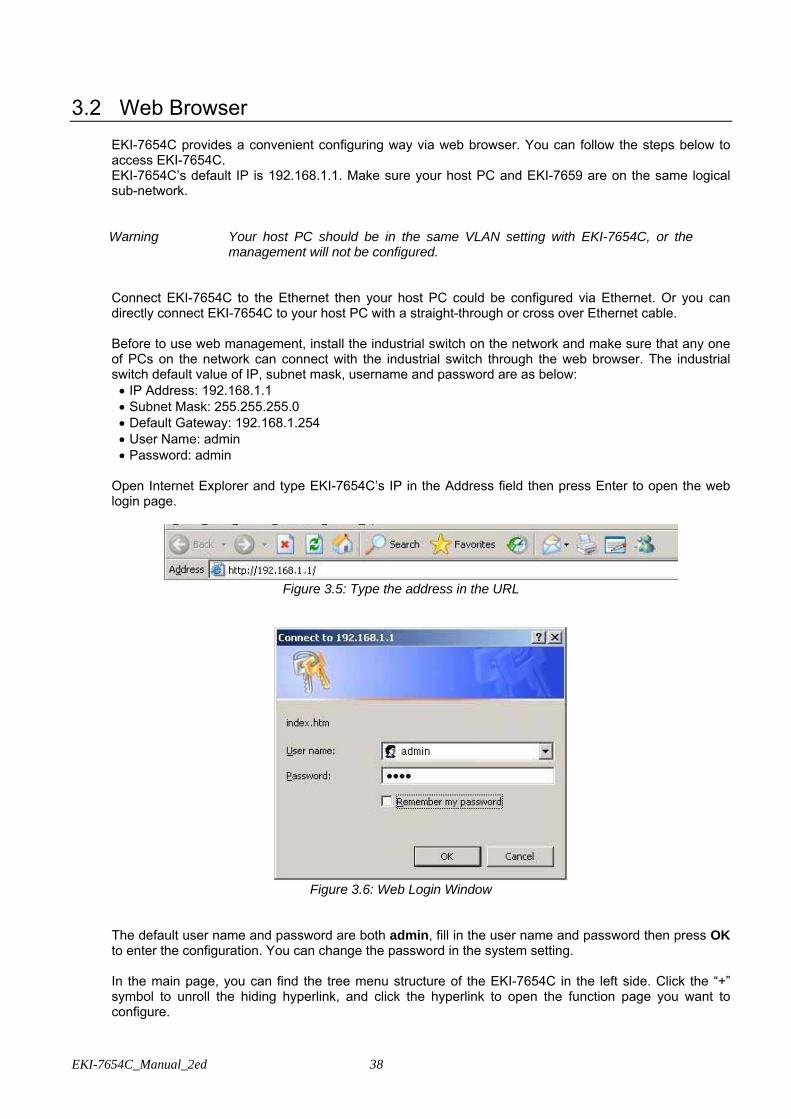
Open Internet Explorer and type EKI-7654C’s IP in the Address field then press Enter to open the web login page.
Figure 3.5: Type the address in the URL
Figure 3.6: Web Login Window
The default user name and password are both admin, fill in the user name and password then press OK to enter the configuration. You can change the password in the system setting. In the main page, you can find the tree menu structure of the EKI-7654C in the left side. Click the “+” symbol to unroll the hiding hyperlink, and click the hyperlink to open the function page you want to configure.
39 Chapter3
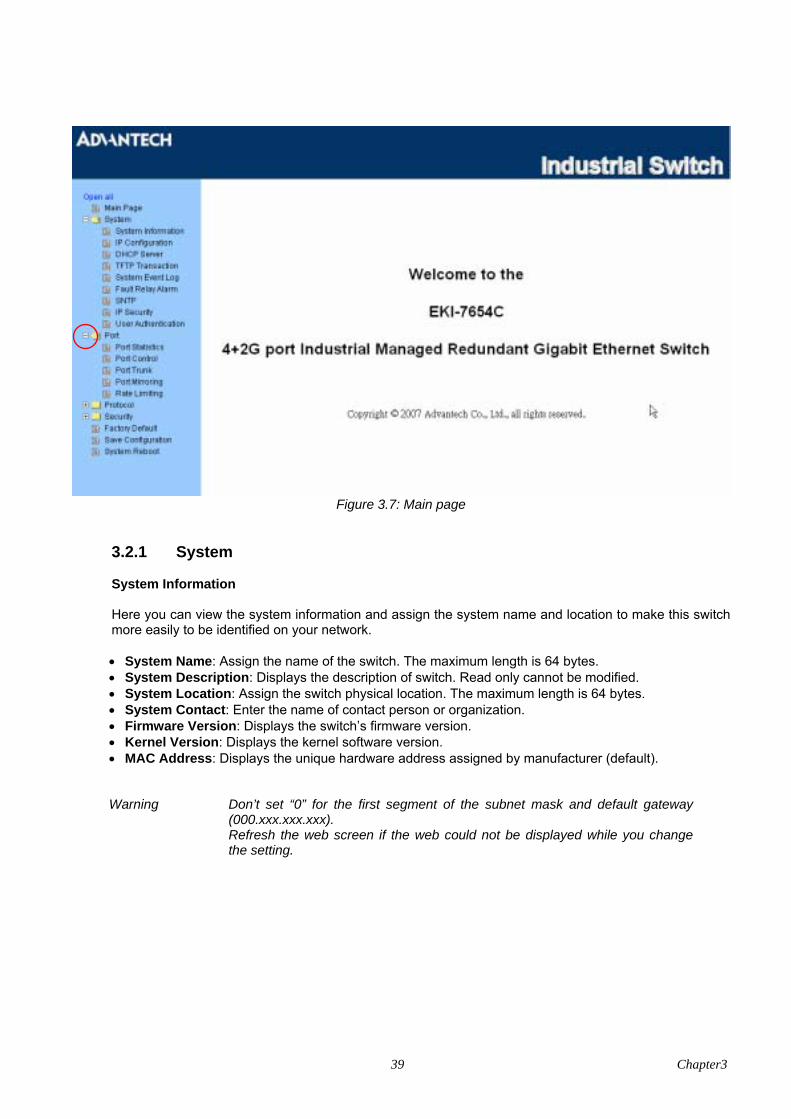
Figure 3.7: Main page
3.2.1 System
System Information
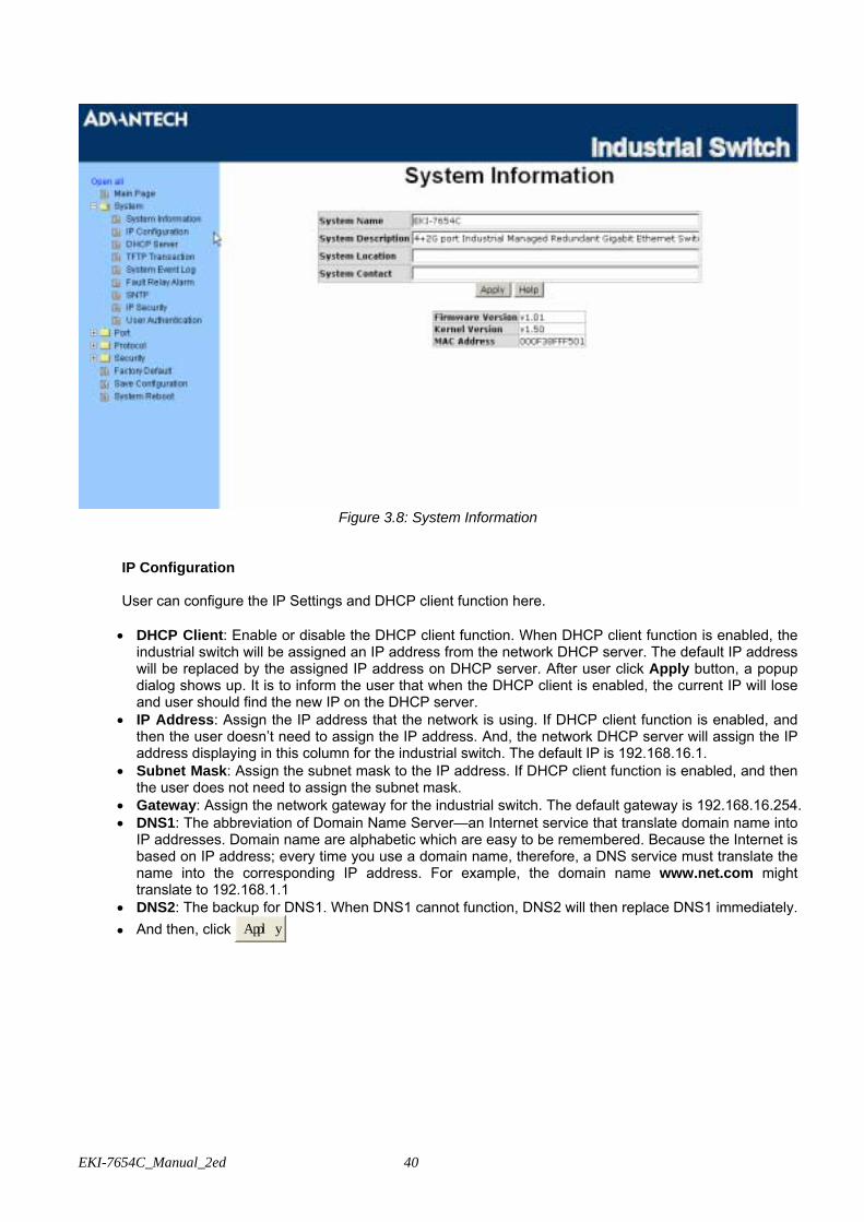
Here you can view the system information and assign the system name and location to make this switch more easily to be identified on your network. • System Name: Assign the name of the switch. The maximum length is 64 bytes. • System Description: Displays the description of switch. Read only cannot be modified. • System Location: Assign the switch physical location. The maximum length is 64 bytes. • System Contact: Enter the name of contact person or organization. • Firmware Version: Displays the switch’s firmware version. • Kernel Version: Displays the kernel software version. • MAC Address: Displays the unique hardware address assigned by manufacturer (default).
Warning Don’t set “0” for the first segment of the subnet mask and default gateway (000.xxx.xxx.xxx).
Refresh the web screen if the web could not be displayed while you change the setting.
EKI-7654C_Manual_2ed 40
Figure 3.8: System Information
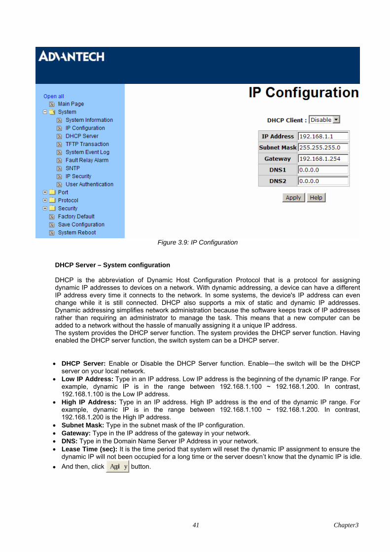
IP Configuration
User can configure the IP Settings and DHCP client function here. • DHCP Client: Enable or disable the DHCP client function. When DHCP client function is enabled, the
industrial switch will be assigned an IP address from the network DHCP server. The default IP address will be replaced by the assigned IP address on DHCP server. After user click Apply button, a popup dialog shows up. It is to inform the user that when the DHCP client is enabled, the current IP will lose and user should find the new IP on the DHCP server.
• IP Address: Assign the IP address that the network is using. If DHCP client function is enabled, and then the user doesn’t need to assign the IP address. And, the network DHCP server will assign the IP address displaying in this column for the industrial switch. The default IP is 192.168.16.1.
• Subnet Mask: Assign the subnet mask to the IP address. If DHCP client function is enabled, and then the user does not need to assign the subnet mask.
• Gateway: Assign the network gateway for the industrial switch. The default gateway is 192.168.16.254. • DNS1: The abbreviation of Domain Name Server—an Internet service that translate domain name into
IP addresses. Domain name are alphabetic which are easy to be remembered. Because the Internet is based on IP address; every time you use a domain name, therefore, a DNS service must translate the name into the corresponding IP address. For example, the domain name www.net.com might translate to 192.168.1.1
• DNS2: The backup for DNS1. When DNS1 cannot function, DNS2 will then replace DNS1 immediately. • And then, click Apply
41 Chapter3
Figure 3.9: IP Configuration
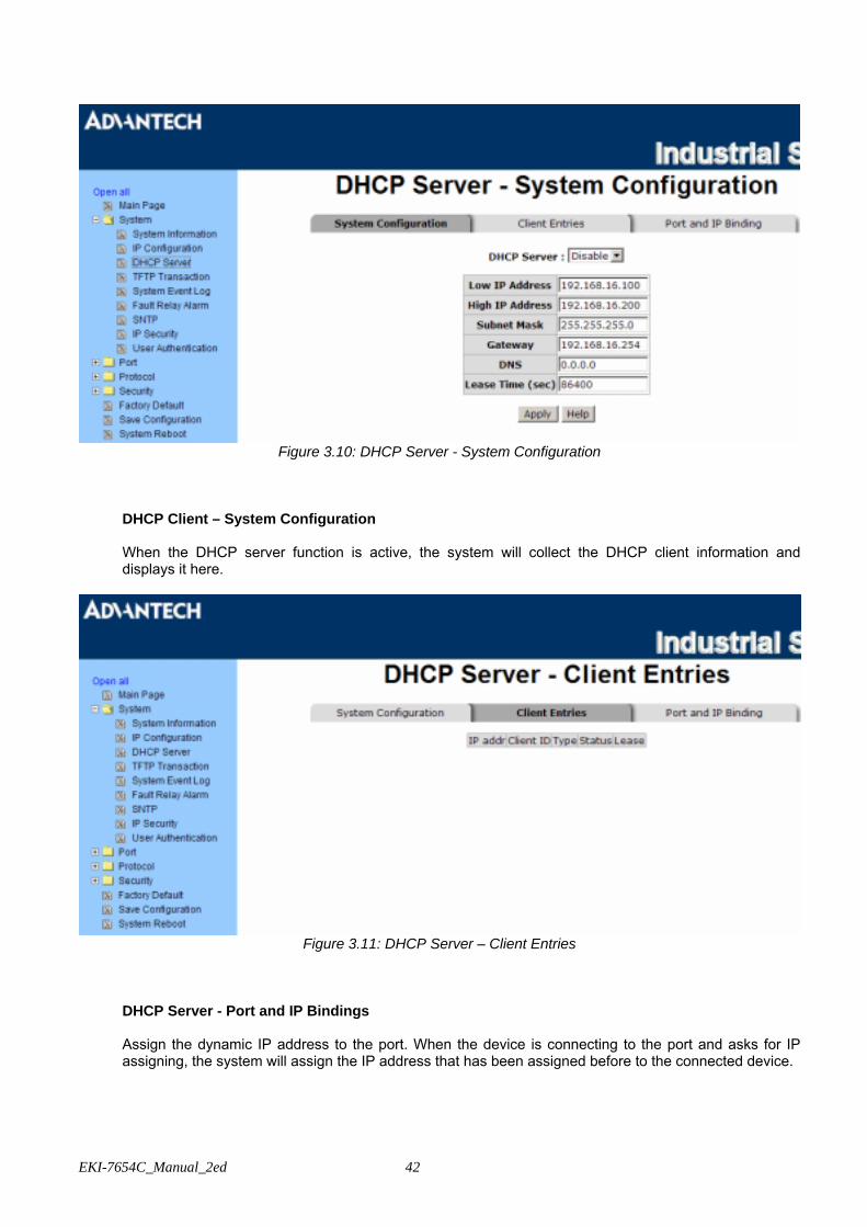
DHCP Server – System configuration
DHCP is the abbreviation of Dynamic Host Configuration Protocol that is a protocol for assigning dynamic IP addresses to devices on a network. With dynamic addressing, a device can have a different IP address every time it connects to the network. In some systems, the device's IP address can even change while it is still connected. DHCP also supports a mix of static and dynamic IP addresses. Dynamic addressing simplifies network administration because the software keeps track of IP addresses rather than requiring an administrator to manage the task. This means that a new computer can be added to a network without the hassle of manually assigning it a unique IP address. The system provides the DHCP server function. The system provides the DHCP server function. Having enabled the DHCP server function, the switch system can be a DHCP server. • DHCP Server: Enable or Disable the DHCP Server function. Enable—the switch will be the DHCP
server on your local network. • Low IP Address: Type in an IP address. Low IP address is the beginning of the dynamic IP range. For
example, dynamic IP is in the range between 192.168.1.100 ~ 192.168.1.200. In contrast, 192.168.1.100 is the Low IP address.
• High IP Address: Type in an IP address. High IP address is the end of the dynamic IP range. For example, dynamic IP is in the range between 192.168.1.100 ~ 192.168.1.200. In contrast, 192.168.1.200 is the High IP address.
• Subnet Mask: Type in the subnet mask of the IP configuration. • Gateway: Type in the IP address of the gateway in your network. • DNS: Type in the Domain Name Server IP Address in your network. • Lease Time (sec): It is the time period that system will reset the dynamic IP assignment to ensure the
dynamic IP will not been occupied for a long time or the server doesn’t know that the dynamic IP is idle. • And then, click Apply button.
EKI-7654C_Manual_2ed 42
Figure 3.10: DHCP Server - System Configuration
DHCP Client – System Configuration When the DHCP server function is active, the system will collect the DHCP client information and displays it here.
Figure 3.11: DHCP Server – Client Entries
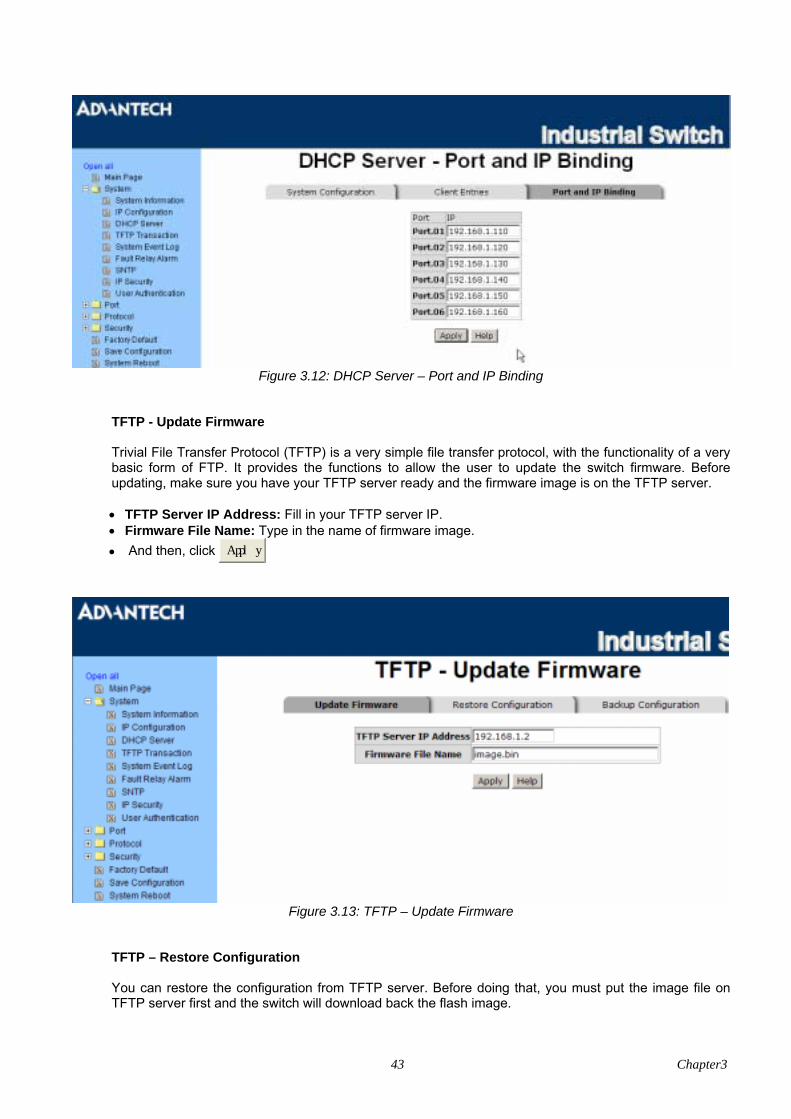
DHCP Server - Port and IP Bindings Assign the dynamic IP address to the port. When the device is connecting to the port and asks for IP assigning, the system will assign the IP address that has been assigned before to the connected device.
43 Chapter3
Figure 3.12: DHCP Server – Port and IP Binding
TFTP - Update Firmware Trivial File Transfer Protocol (TFTP) is a very simple file transfer protocol, with the functionality of a very basic form of FTP. It provides the functions to allow the user to update the switch firmware. Before updating, make sure you have your TFTP server ready and the firmware image is on the TFTP server. • TFTP Server IP Address: Fill in your TFTP server IP. • Firmware File Name: Type in the name of firmware image. • And then, click Apply
Figure 3.13: TFTP – Update Firmware
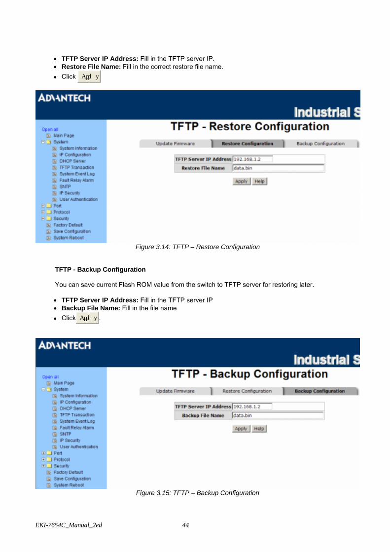
TFTP – Restore Configuration
You can restore the configuration from TFTP server. Before doing that, you must put the image file on TFTP server first and the switch will download back the flash image.
EKI-7654C_Manual_2ed 44
• TFTP Server IP Address: Fill in the TFTP server IP. • Restore File Name: Fill in the correct restore file name. • Click Apply
Figure 3.14: TFTP – Restore Configuration
TFTP - Backup Configuration
You can save current Flash ROM value from the switch to TFTP server for restoring later. • TFTP Server IP Address: Fill in the TFTP server IP • Backup File Name: Fill in the file name • Click Apply.
Figure 3.15: TFTP – Backup Configuration
45 Chapter3
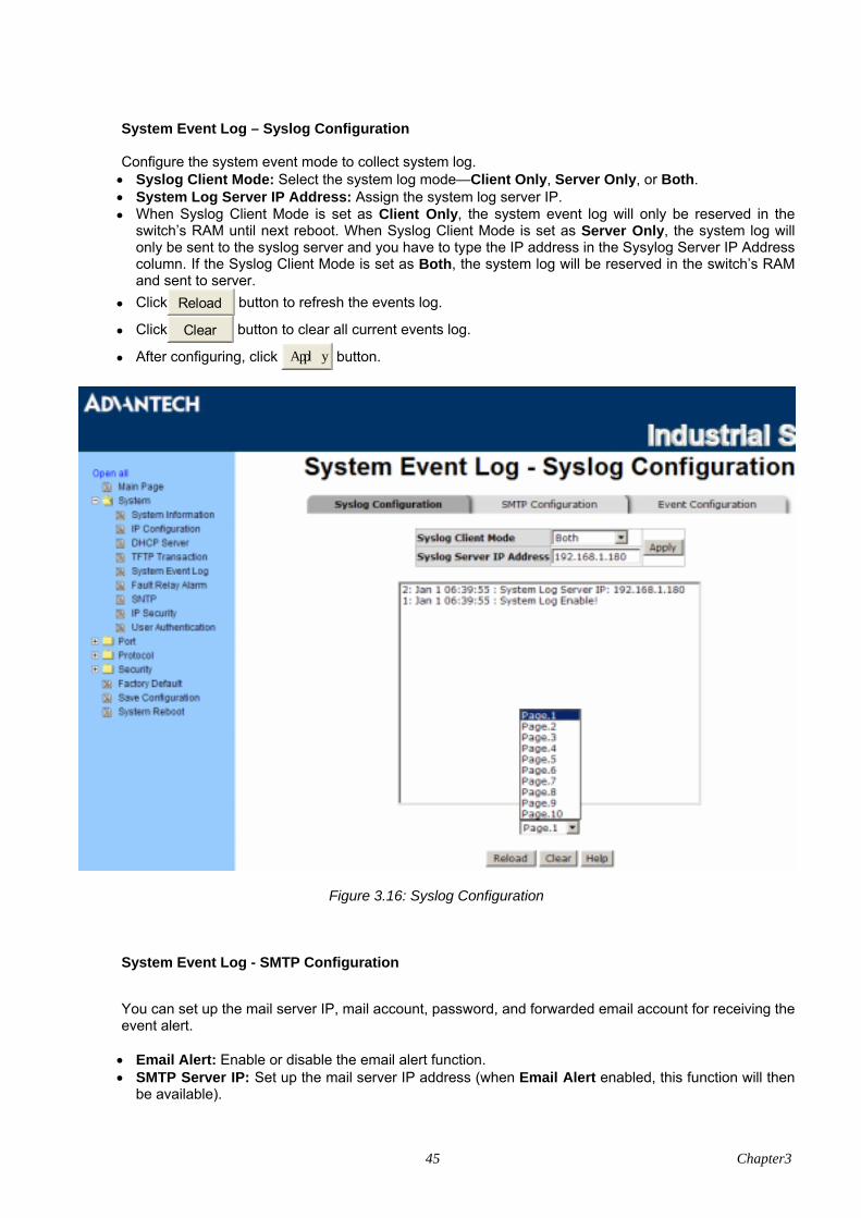
System Event Log – Syslog Configuration
Configure the system event mode to collect system log. • Syslog Client Mode: Select the system log mode—Client Only, Server Only, or Both. • System Log Server IP Address: Assign the system log server IP. • When Syslog Client Mode is set as Client Only, the system event log will only be reserved in the
switch’s RAM until next reboot. When Syslog Client Mode is set as Server Only, the system log will only be sent to the syslog server and you have to type the IP address in the Sysylog Server IP Address column. If the Syslog Client Mode is set as Both, the system log will be reserved in the switch’s RAM and sent to server.
• Click Reload button to refresh the events log.
• Click Clear button to clear all current events log.
• After configuring, click Apply button.
Figure 3.16: Syslog Configuration
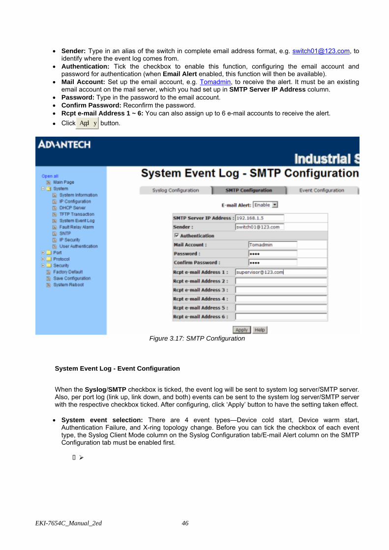
System Event Log - SMTP Configuration
You can set up the mail server IP, mail account, password, and forwarded email account for receiving the event alert. • Email Alert: Enable or disable the email alert function. • SMTP Server IP: Set up the mail server IP address (when Email Alert enabled, this function will then
be available).
EKI-7654C_Manual_2ed 46
• Sender: Type in an alias of the switch in complete email address format, e.g. [email protected], to identify where the event log comes from.
• Authentication: Tick the checkbox to enable this function, configuring the email account and password for authentication (when Email Alert enabled, this function will then be available).
• Mail Account: Set up the email account, e.g. Tomadmin, to receive the alert. It must be an existing email account on the mail server, which you had set up in SMTP Server IP Address column.
• Password: Type in the password to the email account. • Confirm Password: Reconfirm the password. • Rcpt e-mail Address 1 ~ 6: You can also assign up to 6 e-mail accounts to receive the alert. • Click Apply button.
Figure 3.17: SMTP Configuration
System Event Log - Event Configuration
When the Syslog/SMTP checkbox is ticked, the event log will be sent to system log server/SMTP server. Also, per port log (link up, link down, and both) events can be sent to the system log server/SMTP server with the respective checkbox ticked. After configuring, click ‘Apply’ button to have the setting taken effect. • System event selection: There are 4 event types—Device cold start, Device warm start,
Authentication Failure, and X-ring topology change. Before you can tick the checkbox of each event type, the Syslog Client Mode column on the Syslog Configuration tab/E-mail Alert column on the SMTP Configuration tab must be enabled first.
Device cold start: When the device executes cold start action, the system will issue a log
event. Device warm start: When the device executes warm start, the system will issue a log event. Authentication Failure: When the SNMP authentication fails, the system will issue a log event. X-ring topology change: When the X-ring topology has changed, the system will issue a log
event.

47 Chapter3
• Port event selection: Also, before the drop-down menu items are available, the Syslog Client Mode
column on the Syslog Configuration tab/E-mail Alert column on the SMTP Configuration tab must be enabled first. Those drop-down menu items have 3 selections—Link UP, Link Down, and Link UP & Link Down. Disable means no event will be sent to the system log server/SMTP server.
Link UP: The system will issue a log message when port connection links up only. Link Down: The system will issue a log message when port connection links down only. Link UP & Link Down: The system will issue a log message when port connection is up and
down.
Figure 3.18: Event Configuration
Fault Relay Alarm • Power Failure: Tick the checkbox to enable the function of lighting up the FAULT LED on the panel
when power fails. • Port Link Down/Broken: Tick the checkbox to enable the function of lighting up FAULT LED on the
panel when ports’ states are link-down or broken.
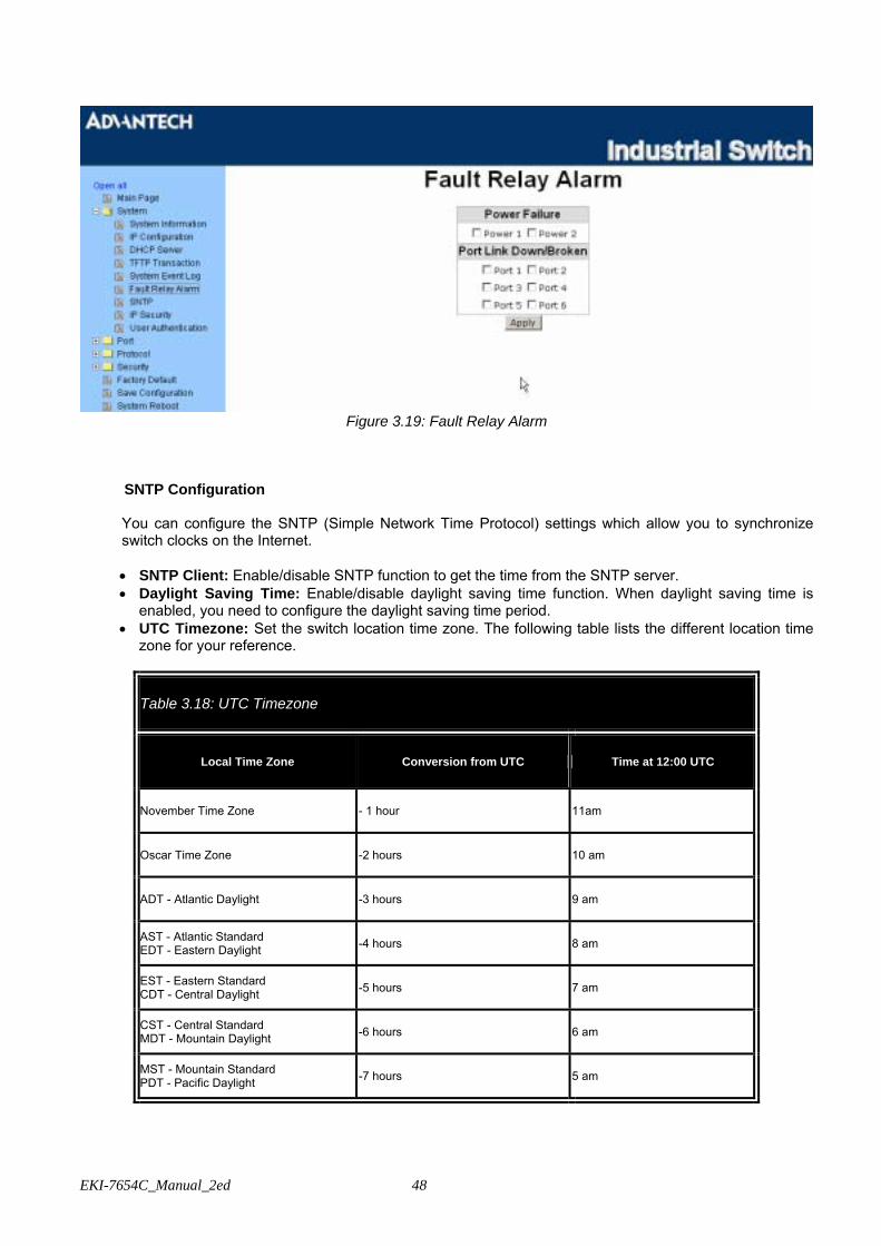
EKI-7654C_Manual_2ed 48
Figure 3.19: Fault Relay Alarm
SNTP Configuration You can configure the SNTP (Simple Network Time Protocol) settings which allow you to synchronize switch clocks on the Internet.
• SNTP Client: Enable/disable SNTP function to get the time from the SNTP server. • Daylight Saving Time: Enable/disable daylight saving time function. When daylight saving time is
enabled, you need to configure the daylight saving time period. • UTC Timezone: Set the switch location time zone. The following table lists the different location time
zone for your reference.
Table 3.18: UTC Timezone
Local Time Zone Conversion from UTC Time at 12:00 UTC
November Time Zone - 1 hour 11am
Oscar Time Zone -2 hours 10 am
ADT - Atlantic Daylight -3 hours 9 am
AST - Atlantic Standard EDT - Eastern Daylight -4 hours 8 am
EST - Eastern Standard CDT - Central Daylight -5 hours 7 am
CST - Central Standard MDT - Mountain Daylight -6 hours 6 am
MST - Mountain Standard PDT - Pacific Daylight -7 hours 5 am

49 Chapter3
PST - Pacific Standard ADT - Alaskan Daylight -8 hours 4 am
ALA - Alaskan Standard -9 hours 3 am
HAW - Hawaiian Standard -10 hours 2 am
Nome, Alaska -11 hours 1 am
CET - Central European FWT - French Winter MET - Middle European MEWT - Middle European Winter SWT - Swedish Winter
+1 hour 1 pm
EET - Eastern European, USSR Zone 1 +2 hours 2 pm
BT - Baghdad, USSR Zone 2 +3 hours 3 pm
ZP4 - USSR Zone 3 +4 hours 4 pm
ZP5 - USSR Zone 4 +5 hours 5 pm
ZP6 - USSR Zone 5 +6 hours 6 pm
WAST - West Australian Standard +7 hours 7 pm
CCT - China Coast, USSR Zone 7 +8 hours 8 pm
JST - Japan Standard, USSR Zone 8 +9 hours 9 pm
EAST - East Australian Standard GST Guam Standard, USSR Zone 9 +10 hours 10 pm
IDLE - International Date Line NZST - New Zealand Standard NZT - New Zealand
+12 hours Midnight
• SNTP Sever URL: Set the SNTP server IP address. • Switch Timer: Displays the current time of the switch. • Daylight Saving Period: Set up the Daylight Saving beginning time and Daylight Saving ending time.
Both will be different in every year. • Daylight Saving Offset (mins): For non-US and European countries, specify the amount of time for
day light savings. • Click Apply button.

EKI-7654C_Manual_2ed 50
Figure 3.20: SNTP Configuration
IP Security IP security function allows the user to assign 10 specific IP addresses that have permission to access the switch through the web browser for the securing switch management.
• IP Security Mode: When this option is in Enable mode, the Enable HTTP Server and Enable Telnet
Server checkboxes will then be available. • Enable HTTP Server: When this checkbox is ticked, the IP addresses among Security IP1 ~ IP10 will
be allowed to access this switch via HTTP service. • Enable Telnet Server: When this checkbox is ticked, the IP addresses among Security IP1 ~ IP10 will
be allowed to access this switch via telnet service. • Security IP 1 ~ 10: The system allows the user to assign up to 10 specific IP addresses for access
security. Only these 10 IP addresses can access and manage the switch through the HTTP/Telnet service.
• And then, click Apply button to apply the configuration.
Note Remember to execute the “Save Configuration” action, otherwise the new configuration will lose when switch power off.

51 Chapter3
Figure 3.21: IP Security
User Authentication
Change web management login user name and password for the management security issue.
• User name: Key in the new user name (The default is “admin”). • Password: Key in the new password (The default is “admin”). • Confirm password: Re-type the new password. • And then, click Apply button to apply the configuration.
Figure 3.22: User Authentication

EKI-7654C_Manual_2ed 52
3.2.2 Port Port setting includes Port Statistics, Port Control, Port Trunk, Port Mirroring, and Rate Limiting. The user can use this interface to set the parameters and control the packet flow among the ports. Port Statistics
The following information provides the current port statistic information.
• Port: Displays the port number. • Type: Displays the media type of the port. • Link: The status of linking—‘Up’ or ‘Down’. • State: The user can set the state of the port as ‘Enable’ or ‘Disable’ via Port Control. When the state is
disabled, the port will not transmit or receive any packet. • Tx Good Packet: The counts of transmitting good packets via this port. • Tx Bad Packet: The counts of transmitting bad packets (including undersize [less than 64 bytes],
oversize, CRC Align errors, fragments and jabbers packets) via this port. • Rx Good Packet: The counts of receiving good packets via this port. • Rx Bad Packet: The counts of receiving bad packets (including undersize [less than 64 bytes],
oversize, CRC error, fragments and jabbers) via this port. • Tx Abort Packet: The aborted packet while transmitting. • Packet Collision: The counts of collision packet. • Packet Dropped: The counts of dropped packet. • Rx Bcast Packet: The counts of broadcast packet. • Rx Mcast Packet: The counts of multicast packet. • Click Clear button to clean all counts.
Figure 3.23: Port Statistics
Port Control In Port Control, you can pull down the selection items to set the parameters of each port to control the transmitting/receiving packets.
• Port: Select the port that you want to configure. • State: Current port status. The port can be set to disable or enable mode. If the port state is set as
‘Disable’, it will not receive or transmit any packet. • Negotiation: Auto and Force. Being set as Auto, the speed and duplex mode are negotiated
automatically. When you set it as Force, you have to assign the speed and duplex mode manually.

53 Chapter3
• Speed: It is available for selecting when the Negotiation column is set as Force. When the Negotiation column is set as Auto, this column is read only.
• Duplex: It is available for selecting when the Negotiation column is set as Force. When the Negotiation column is set as Auto, this column is read only.
• Flow Control: Set flow control function as Enable or Disable. When enabled, once the device exceed the input data rate of another device as a result the receiving device will send a PAUSE frame which halts the transmission of the sender for a specified period of time. When disabled, the receiving device will drop the packet if too much to process.
• Security: Once the Security selection is set as ‘On’, any access from the device which connects to this port will be blocked unless the MAC address of the device is included in the static MAC address table. See the segment of Static MAC Table.
• Click Apply button to make the configuration effective.
Figure 3.24: Port Control
Port Trunk The Link Aggregation Control Protocol (LACP) provides a standardized means for exchanging information between Partner Systems on a link to allow their Link Aggregation Control instances to reach agreement on the identity of the Link Aggregation Group to which the link belongs, move the link to that Link Aggregation Group, and enable its transmission and reception functions in an orderly manner. Link aggregation lets you group up to 4 ports into one dedicated connections. This feature can expand bandwidth to a device on the network. LACP operation requires full-duplex mode, more detail information refers to IEEE 802.3ad.
Aggregator setting
• System Priority: A value which is used to identify the active LACP. The switch with the lowest value
has the highest priority and is selected as the active LACP. • Group ID: There are four trunk groups to be selected. Choose the ‘Group ID’ and click Select button. • LACP: When enabled, the trunk group is using LACP. A port which joins an LACP trunk group has to
make an agreement with its member ports first. When disabled, the trunk group is a static trunk group. The advantage of having the LACP disabled is that a port joins the trunk group without any handshaking with its member ports. But member ports won’t know that they should be aggregated together to form a logic trunk group.
• Work ports: This column field allows the user to type in the total number of active port up to four. With LACP trunk group, you create a trunk group by connecting two or more switches (e.g. you assign four ports to be the members of a trunk group whose work ports column field is set as two). The exceed
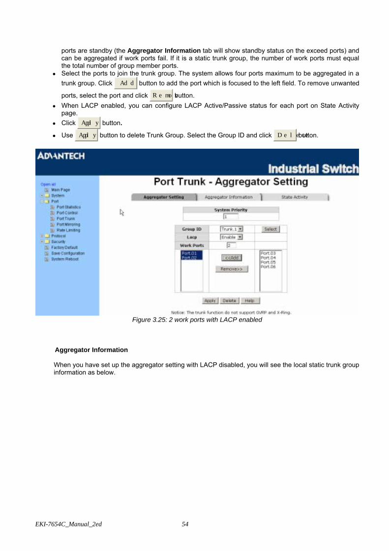
EKI-7654C_Manual_2ed 54
ports are standby (the Aggregator Information tab will show standby status on the exceed ports) and can be aggregated if work ports fail. If it is a static trunk group, the number of work ports must equal the total number of group member ports.
• Select the ports to join the trunk group. The system allows four ports maximum to be aggregated in a trunk group. Click Add button to add the port which is focused to the left field. To remove unwanted
ports, select the port and click Remov button. • When LACP enabled, you can configure LACP Active/Passive status for each port on State Activity
page. • Click Apply button.
• Use Apply button to delete Trunk Group. Select the Group ID and click Delete button.
Figure 3.25: 2 work ports with LACP enabled
Aggregator Information When you have set up the aggregator setting with LACP disabled, you will see the local static trunk group information as below.
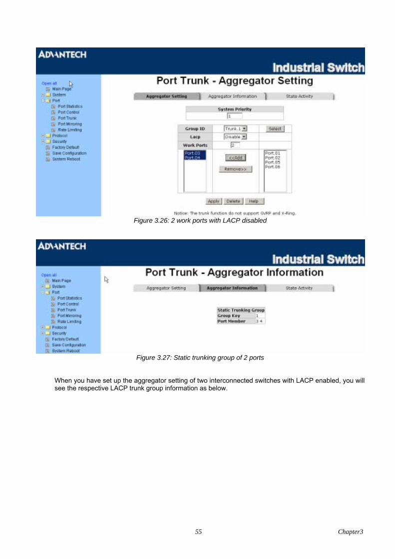
55 Chapter3
Figure 3.26: 2 work ports with LACP disabled
Figure 3.27: Static trunking group of 2 ports
When you have set up the aggregator setting of two interconnected switches with LACP enabled, you will see the respective LACP trunk group information as below.
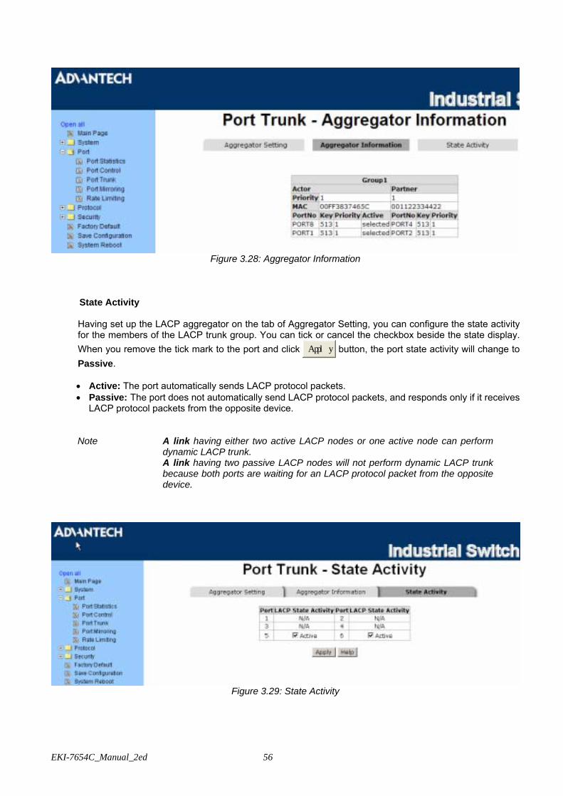
EKI-7654C_Manual_2ed 56
Figure 3.28: Aggregator Information
State Activity Having set up the LACP aggregator on the tab of Aggregator Setting, you can configure the state activity for the members of the LACP trunk group. You can tick or cancel the checkbox beside the state display. When you remove the tick mark to the port and click Apply button, the port state activity will change to Passive.
• Active: The port automatically sends LACP protocol packets. • Passive: The port does not automatically send LACP protocol packets, and responds only if it receives
LACP protocol packets from the opposite device.
Note A link having either two active LACP nodes or one active node can perform dynamic LACP trunk.
A link having two passive LACP nodes will not perform dynamic LACP trunk because both ports are waiting for an LACP protocol packet from the opposite device.
Figure 3.29: State Activity

57 Chapter3
Port Mirroring The Port mirroring is a method for monitoring traffic in switched networks. Traffic through ports can be monitored by one specific port which means traffic goes in or out monitored (source) ports will be duplicated into mirroring (destination) port.
• Destination Port: There is only one port can be selected to be the destination (mirroring) port for
monitoring both RX and TX traffic which come from the source port. Or, use one of two ports for monitoring RX traffic only and the other one for TX traffic only. The user can connect the mirroring port to LAN analyzer or Netxray.
• Source Port: The ports that the user wants to monitor. All monitored port traffic will be copied to mirroring (destination) port. The user can select multiple source ports by ticking the RX or TX checkboxes to be monitored.
• And then, click Apply button.
Figure 3.30: Port Mirroring
Rate Limiting Here you can set up every port’s frame limitation type and bandwidth rate.
• Ingress Limit Frame type: Select the frame type you want to filter. The frame types have 4 options for
selecting: All, Broadcast/Multicast/Flooded Unicast, Broadcast/Multicast, and Broadcast only. The four frame type options are for ingress frames limitation. The egress rate only supports ‘All’ type.
All ports support port ingress and egress rate control. For example, assume port 1 is 10Mbps; the user can set the effective egress rate of port 1 as 1Mbps, ingress rate 500Kbps. The switch performs the ingress rate by packet counter to meet the specified rate
• Ingress: Enter the port effective ingress rate (The default value is “0”) • Egress: Enter the port effective egress rate (The default value is “0”) • And then, click Apply to make the settings taken effect.

EKI-7654C_Manual_2ed 58
Figure 3.31: Rate Limiting

59 Chapter3
3.2.3 Protocol
The user can set the layer 2 protocol setting via this interface.
VLAN configuration A Virtual LAN (VLAN) is a logical network grouping that limits the broadcast domain, which would allow you to isolate network traffic, so only the members of the same VLAN will receive traffic from the ones of the same VLAN. Basically, creating a VLAN from a switch is logically equivalent of reconnecting a group of network devices to another Layer 2 switch. However, all the network devices are still plugged into the same switch physically. The switch supports Port-based and 802.1Q (tagged-based) VLAN. The default configuration of VLAN operation mode is “Disable”.
Figure 3.32: VLAN Configuration
VLAN configuration - Port-based VLAN Packets can go among only members of the same VLAN group. Note all unselected ports are treated as belonging to another single VLAN. If the port-based VLAN enabled, the VLAN-tagging is ignored. In order for an end station to send packets to different VLAN groups, it itself has to be either capable of tagging packets it sends with VLAN tags or attached to a VLAN-aware bridge that is capable of classifying and tagging the packet with different VLAN ID based on not only default PVID but also other information about the packet, such as the protocol.

EKI-7654C_Manual_2ed 60
Figure 3.33: Port based mode
• Pull down the selection item and focus on Port Based then press Apply button to set the VLAN
Operation Mode in Port Based mode. • Click Add button to add a new VLAN group.
Figure 3.34: Port based mode-Add interface
• Enter the group name and VLAN ID. Add the port number having selected into the right field to group
these members to be a VLAN group or remove any of them listed in the right field from the VLAN. • And then, click Apply button to have the settings taken effect. • You will see the VLAN displays.

61 Chapter3
Figure 3.35: Port Based Edit/Delete interface
• Use Delete button to delete the VLAN.
• Use Edit button to modify group name, VLAN ID, or add/remove the members of the existing VLAN group.
Note Remember to execute the “Save Configuration” action, otherwise the new
configuration will lose when switch power off. 802.1Q VLAN
Tagged-based VLAN is an IEEE 802.1Q specification standard. Therefore, it is possible to create a VLAN across devices from different switch venders. IEEE 802.1Q VLAN uses a technique to insert a “tag” into the Ethernet frames. Tag contains a VLAN Identifier (VID) that indicates the VLAN numbers. You can create Tag-based VLAN, and enable or disable GVRP protocol. There are 256 VLAN groups to provide configuration. Enable 802.1Q VLAN, all ports on the switch belong to default VLAN of VID 1. The default VLAN can’t be deleted. GVRP (GARP VLAN Registration Protocol) is a protocol that facilitates control of virtual local area networks (VLANs) within a larger network. GVRP conforms to the IEEE 802.1Q specification, which defines a method of tagging frames with VLAN configuration data. This allows network devices to dynamically exchange VLAN configuration information with other devices. GVRP is based on GARP (Generic Attribute Registration Protocol), a protocol that defines procedures by which end stations and switches in a local area network (LAN) can register and de-register attributes, such as identifiers or addresses, with each other. Every end station and switch thus has a current record of all the other end stations and switches that can be reached.
802.1Q Configuration • Pull down the selection item and focus on 802.1Q then press Apply button to set the VLAN
Operation Mode in 802.1Q mode. • Enable GVRP Protocol: Tick the checkbox to enable GVRP protocol. This checkbox is available while
the VLAN Operation Mode is in 802.1Q mode.
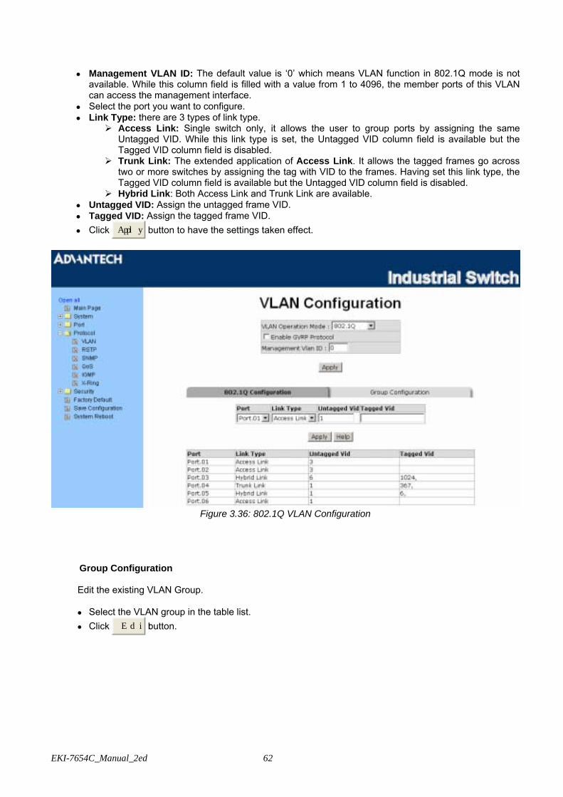
EKI-7654C_Manual_2ed 62
• Management VLAN ID: The default value is ‘0’ which means VLAN function in 802.1Q mode is not available. While this column field is filled with a value from 1 to 4096, the member ports of this VLAN can access the management interface.
• Select the port you want to configure. • Link Type: there are 3 types of link type.
Access Link: Single switch only, it allows the user to group ports by assigning the same Untagged VID. While this link type is set, the Untagged VID column field is available but the Tagged VID column field is disabled.
Trunk Link: The extended application of Access Link. It allows the tagged frames go across two or more switches by assigning the tag with VID to the frames. Having set this link type, the Tagged VID column field is available but the Untagged VID column field is disabled.
Hybrid Link: Both Access Link and Trunk Link are available. • Untagged VID: Assign the untagged frame VID. • Tagged VID: Assign the tagged frame VID. • Click Apply button to have the settings taken effect.
Figure 3.36: 802.1Q VLAN Configuration
Group Configuration Edit the existing VLAN Group. • Select the VLAN group in the table list. • Click Edit button.
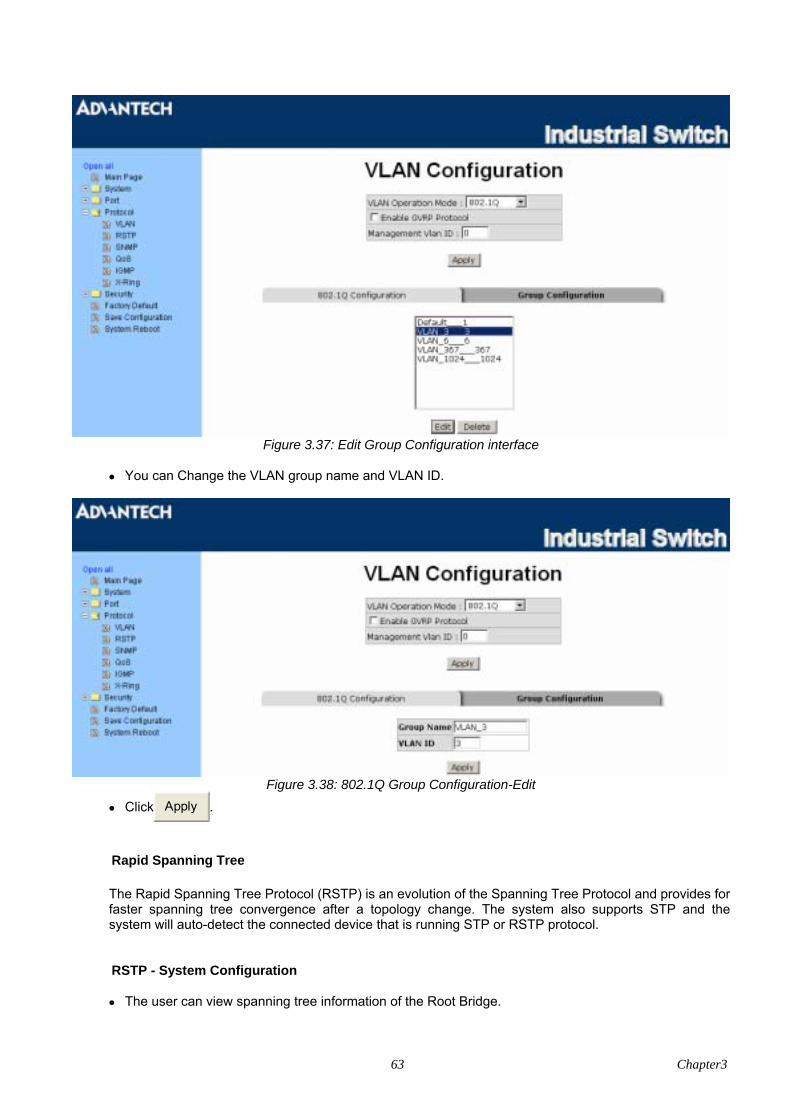
63 Chapter3
Figure 3.37: Edit Group Configuration interface
• You can Change the VLAN group name and VLAN ID.
Figure 3.38: 802.1Q Group Configuration-Edit
• Click Apply .
Rapid Spanning Tree
The Rapid Spanning Tree Protocol (RSTP) is an evolution of the Spanning Tree Protocol and provides for faster spanning tree convergence after a topology change. The system also supports STP and the system will auto-detect the connected device that is running STP or RSTP protocol.
RSTP - System Configuration • The user can view spanning tree information of the Root Bridge.
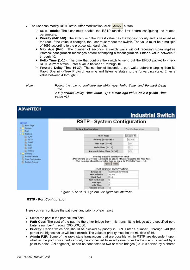
EKI-7654C_Manual_2ed 64
• The user can modify RSTP state. After modification, click Apply button. RSTP mode: The user must enable the RSTP function first before configuring the related
parameters. Priority (0-61440): The switch with the lowest value has the highest priority and is selected as
the root. If the value is changed, the user must reboot the switch. The value must be a multiple of 4096 according to the protocol standard rule.
Max Age (6-40): The number of seconds a switch waits without receiving Spanning-tree Protocol configuration messages before attempting a reconfiguration. Enter a value between 6 through 40.
Hello Time (1-10): The time that controls the switch to send out the BPDU packet to check RSTP current status. Enter a value between 1 through 10.
Forward Delay Time (4-30): The number of seconds a port waits before changing from its Rapid Spanning-Tree Protocol learning and listening states to the forwarding state. Enter a value between 4 through 30.
Note Follow the rule to configure the MAX Age, Hello Time, and Forward Delay
Time. 2 x (Forward Delay Time value –1) > = Max Age value >= 2 x (Hello Time
value +1)
Figure 3.39: RSTP System Configuration interface
RSTP - Port Configuration
Here you can configure the path cost and priority of each port. • Select the port in the port column field. • Path Cost: The cost of the path to the other bridge from this transmitting bridge at the specified port.
Enter a number 1 through 200,000,000. • Priority: Decide which port should be blocked by priority in LAN. Enter a number 0 through 240 (the
port of the highest value will be blocked). The value of priority must be the multiple of 16. • Admin P2P: Some of the rapid state transactions that are possible within RSTP are dependent upon
whether the port concerned can only be connected to exactly one other bridge (i.e. it is served by a point-to-point LAN segment), or can be connected to two or more bridges (i.e. it is served by a shared
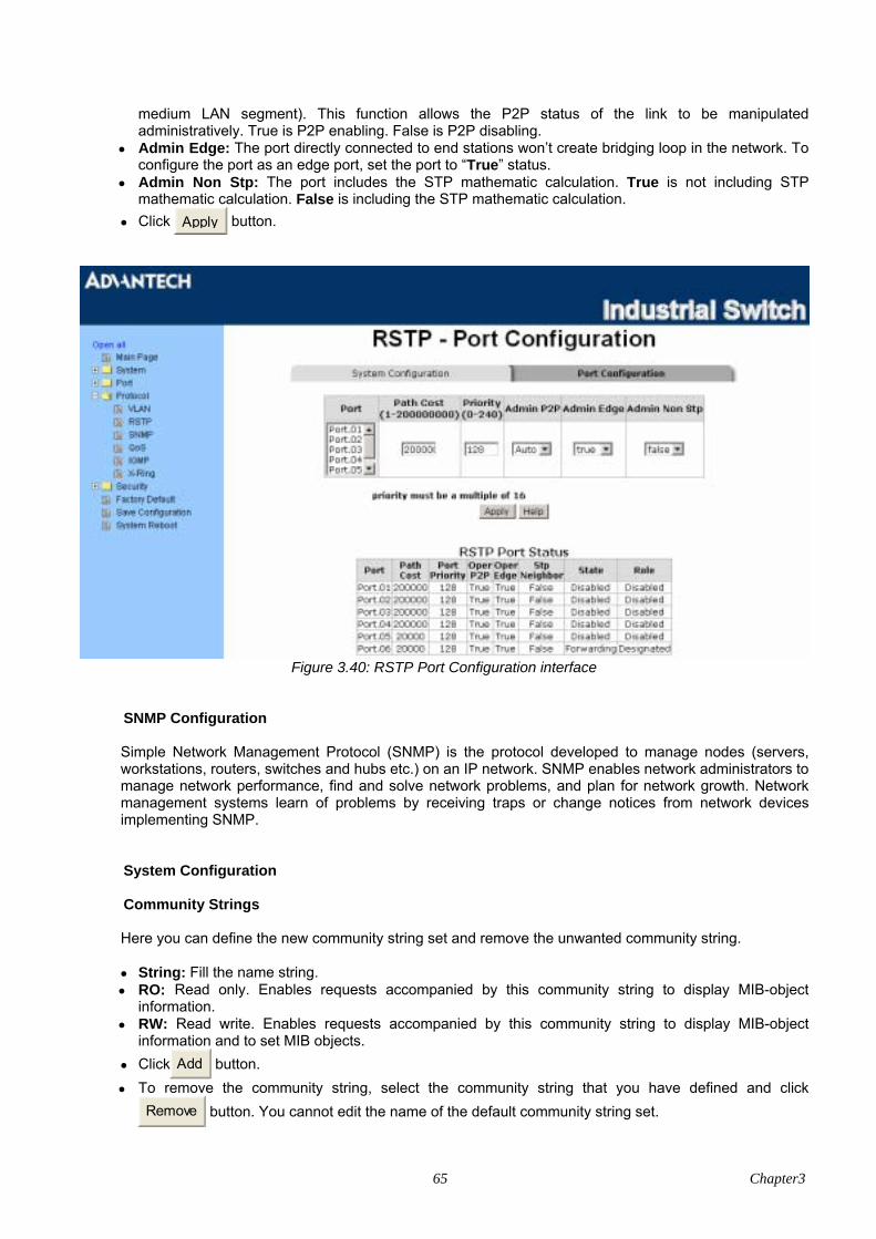
65 Chapter3
medium LAN segment). This function allows the P2P status of the link to be manipulated administratively. True is P2P enabling. False is P2P disabling.
• Admin Edge: The port directly connected to end stations won’t create bridging loop in the network. To configure the port as an edge port, set the port to “True” status.
• Admin Non Stp: The port includes the STP mathematic calculation. True is not including STP mathematic calculation. False is including the STP mathematic calculation.
• Click Apply button.
Figure 3.40: RSTP Port Configuration interface
SNMP Configuration Simple Network Management Protocol (SNMP) is the protocol developed to manage nodes (servers, workstations, routers, switches and hubs etc.) on an IP network. SNMP enables network administrators to manage network performance, find and solve network problems, and plan for network growth. Network management systems learn of problems by receiving traps or change notices from network devices implementing SNMP.
System Configuration
Community Strings Here you can define the new community string set and remove the unwanted community string. • String: Fill the name string. • RO: Read only. Enables requests accompanied by this community string to display MIB-object
information. • RW: Read write. Enables requests accompanied by this community string to display MIB-object
information and to set MIB objects. • Click Add button.
• To remove the community string, select the community string that you have defined and click Remove button. You cannot edit the name of the default community string set.
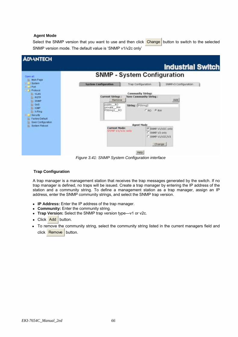
EKI-7654C_Manual_2ed 66
Agent Mode Select the SNMP version that you want to use and then click Change button to switch to the selected SNMP version mode. The default value is ‘SNMP v1/v2c only’
Figure 3.41: SNMP System Configuration interface
Trap Configuration A trap manager is a management station that receives the trap messages generated by the switch. If no trap manager is defined, no traps will be issued. Create a trap manager by entering the IP address of the station and a community string. To define a management station as a trap manager, assign an IP address, enter the SNMP community strings, and select the SNMP trap version.
• IP Address: Enter the IP address of the trap manager. • Community: Enter the community string. • Trap Version: Select the SNMP trap version type—v1 or v2c. • Click Add button.
• To remove the community string, select the community string listed in the current managers field and click Remove button.

67 Chapter3
Figure 3.42: Trap Configuration interface
SNMPV3 Configuration Configure the SNMP V3 function.
Context Table
Configure SNMP v3 context table. Assign the context name of context table. Click Add to add context
name. Click Remove to remove unwanted context name.
User Profile Configure SNMP v3 user table.. • User ID: Set up the user name. • Authentication Password: Set up the authentication password. • Privacy Password: Set up the private password. • Click Add to add context name.
• Click Remove to remove unwanted context name.
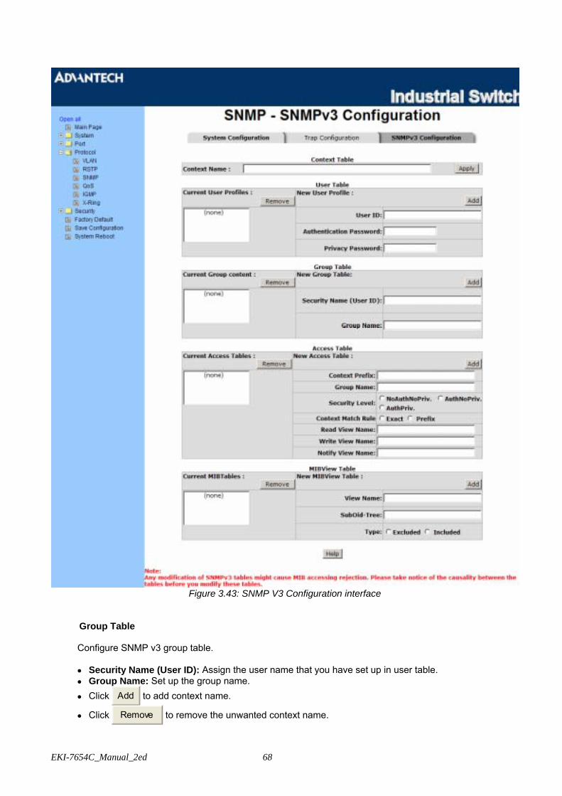
EKI-7654C_Manual_2ed 68
Figure 3.43: SNMP V3 Configuration interface
Group Table Configure SNMP v3 group table. • Security Name (User ID): Assign the user name that you have set up in user table. • Group Name: Set up the group name. • Click Add to add context name.
• Click Remove to remove the unwanted context name.
69 Chapter3
Access Table Configure SNMP v3 access table. • Context Prefix: Set up the context name. • Group Name: Set up the group. • Security Level: Set up the access level. • Context Match Rule: Select the context match rule. • Read View Name: Set up the read view. • Write View Name: Set up the write view. • Notify View Name: Set up the notify view. • Click Add to add context name.
• Click Remove to remove unwanted context name.
MIBview Table Configure MIB view table. • ViewName: Set up the name. • Sub-Oid Tree: Fill the Sub OID. • Type: Select the type—excluded or included. • Click Add to add context name.
• Click Remove to remove unwanted context name.

EKI-7654C_Manual_2ed 70
QoS Configuration Here you can configure Qos policy and priority setting, per port priority setting, COS and TOS setting.
QoS Policy and Priority Type • Qos Policy: Select the QoS policy rule.
Use an 8,4,2,1 weighted fair queuing scheme: The switch will follow 8:4:2:1 rate to process priority queue from High to lowest queue. For example, while the system processing, 1 frame of the lowest queue, 2 frames of the low queue, 4 frames of the middle queue, and 8 frames of the high queue will be processed at the same time in accordance with the 8,4,2,1 policy rule.
Use a strict priority scheme: Always the higher queue will be processed first, except the higher queue is empty.
Priority Type: There are 5 priority type selections available—Port-based, TOS only, COS only, TOS first, and COS first. Disable means no priority type is selected.
• Click Apply button to make the settings effective.
Figure 3.44: QoS Configuration interface
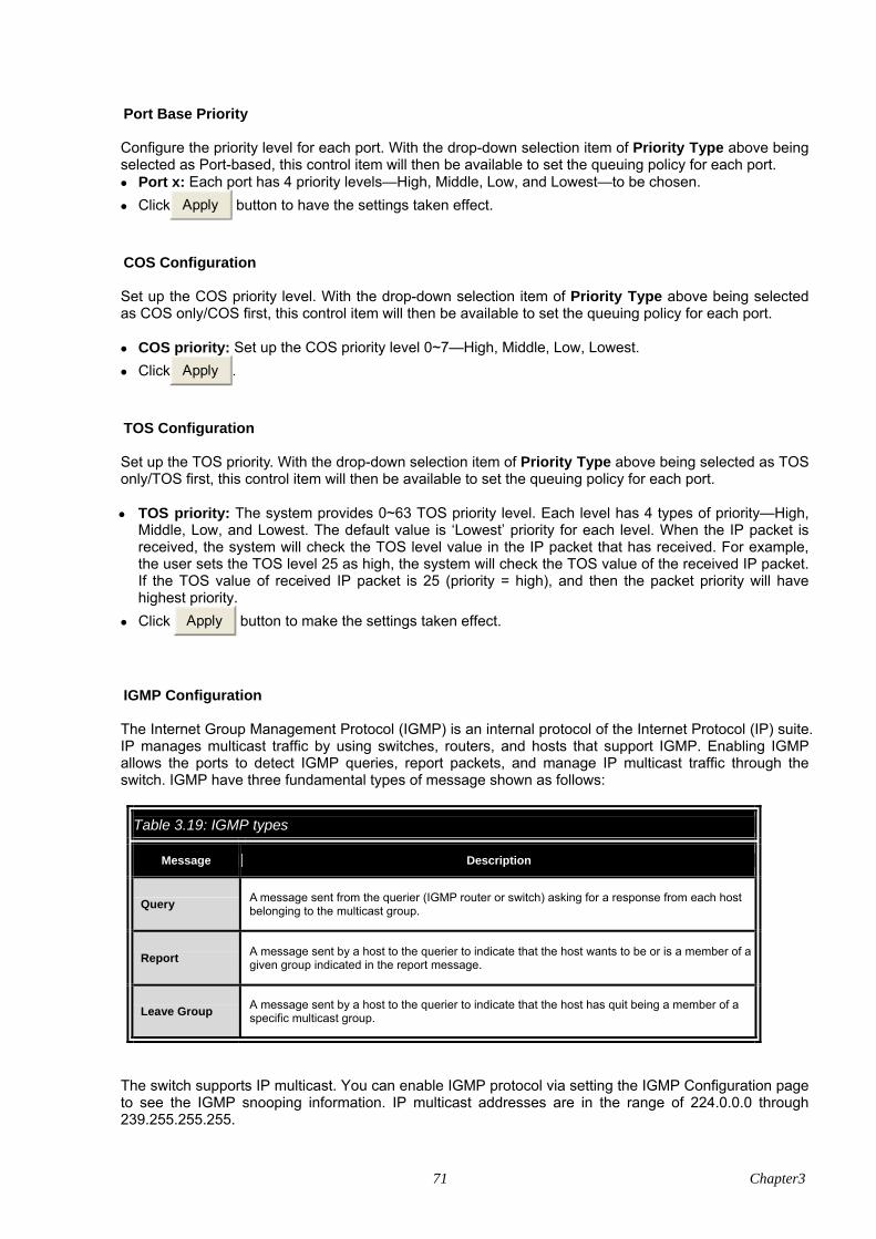
71 Chapter3
Port Base Priority Configure the priority level for each port. With the drop-down selection item of Priority Type above being selected as Port-based, this control item will then be available to set the queuing policy for each port. • Port x: Each port has 4 priority levels—High, Middle, Low, and Lowest—to be chosen. • Click Apply button to have the settings taken effect.
COS Configuration Set up the COS priority level. With the drop-down selection item of Priority Type above being selected as COS only/COS first, this control item will then be available to set the queuing policy for each port. • COS priority: Set up the COS priority level 0~7—High, Middle, Low, Lowest. • Click Apply .
TOS Configuration Set up the TOS priority. With the drop-down selection item of Priority Type above being selected as TOS only/TOS first, this control item will then be available to set the queuing policy for each port. • TOS priority: The system provides 0~63 TOS priority level. Each level has 4 types of priority—High,
Middle, Low, and Lowest. The default value is ‘Lowest’ priority for each level. When the IP packet is received, the system will check the TOS level value in the IP packet that has received. For example, the user sets the TOS level 25 as high, the system will check the TOS value of the received IP packet. If the TOS value of received IP packet is 25 (priority = high), and then the packet priority will have highest priority.
• Click Apply button to make the settings taken effect.
IGMP Configuration The Internet Group Management Protocol (IGMP) is an internal protocol of the Internet Protocol (IP) suite. IP manages multicast traffic by using switches, routers, and hosts that support IGMP. Enabling IGMP allows the ports to detect IGMP queries, report packets, and manage IP multicast traffic through the switch. IGMP have three fundamental types of message shown as follows:
Table 3.19: IGMP types
Message Description
Query A message sent from the querier (IGMP router or switch) asking for a response from each host belonging to the multicast group.
Report A message sent by a host to the querier to indicate that the host wants to be or is a member of a given group indicated in the report message.
Leave Group A message sent by a host to the querier to indicate that the host has quit being a member of a specific multicast group.
The switch supports IP multicast. You can enable IGMP protocol via setting the IGMP Configuration page to see the IGMP snooping information. IP multicast addresses are in the range of 224.0.0.0 through 239.255.255.255.

EKI-7654C_Manual_2ed 72
• IGMP Protocol: Enable or disable the IGMP protocol. • IGMP Query: Select the IGMP query function as Enable or Auto to set the switch as a querier for
IGMP version 2 multicast networks. • Click Apply button.
Figure 3.45: IGMP Configuration interface
X-Ring X-Ring provides a faster redundant recovery than Spanning Tree topology. The action is similar to STP or RSTP, but the algorithms between them are not the same. In the X-Ring topology, every switch should be enabled with X-Ring function and two ports should be assigned as the member ports in the ring. Only one switch in the X-Ring group would be set as the master switch that one of its two member ports would be blocked, called backup port, and another port is called working port. Other switches in the X-Ring group are called working switches and their two member ports are called working ports. When the failure of network connection occurs, the backup port of the master switch (Ring Master) will automatically become a working port to recover from the failure. The switch supports the function and interface for setting the switch as the ring master or not. The ring master can negotiate and place command to other switches in the X-Ring group. If there are 2 or more switches in master mode, the software will select the switch with lowest MAC address number as the ring master. The X-Ring master ring mode can be enabled by setting the X-Ring configuration interface. Also, the user can identify whether the switch is the ring master by checking the R.M. LED indicator on the panel of the switch. The system also supports the Couple Ring that can connect 2 or more X-Ring group for the redundant backup function; Dual Homing function that can prevent connection lose between X-Ring group and upper level/core switch. Apart from the advantages, Central Ring can handle up to 4 rings in the system and has the ability to recover from failure within 10 milliseconds.
• Enable X-Ring: To enable the X-Ring function, tick the checkbox beside the Enable Ring string label.
If this checkbox is not ticked, all the ring functions are unavailable. Enable Ring Master: Tick the checkbox to enable this switch to be the ring master. 1st & 2nd Ring Ports: Pull down the selection menu to assign the ports as the member ports.
1st Ring Port is the working port and 2nd Ring Port is the backup port. When 1st Ring Port fails, the system will automatically upgrade the 2nd Ring Port to be the working port.
• Enable Couple Ring: To enable the coupe ring function, tick the checkbox beside the Enable Couple Ring string label.
Couple port: Assign the member port which is connected to the other ring group.
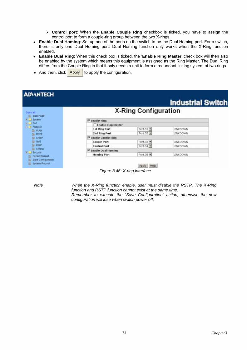
73 Chapter3
Control port: When the Enable Couple Ring checkbox is ticked, you have to assign the control port to form a couple-ring group between the two X-rings.
• Enable Dual Homing: Set up one of the ports on the switch to be the Dual Homing port. For a switch, there is only one Dual Homing port. Dual Homing function only works when the X-Ring function enabled.
• Enable Dual Ring: When this check box is ticked, the ‘Enable Ring Master’ check box will then also be enabled by the system which means this equipment is assigned as the Ring Master. The Dual Ring differs from the Couple Ring in that it only needs a unit to form a redundant linking system of two rings.
• And then, click Apply to apply the configuration.
Figure 3.46: X-ring interface
Note When the X-Ring function enable, user must disable the RSTP. The X-Ring
function and RSTP function cannot exist at the same time. Remember to execute the “Save Configuration” action, otherwise the new
configuration will lose when switch power off.
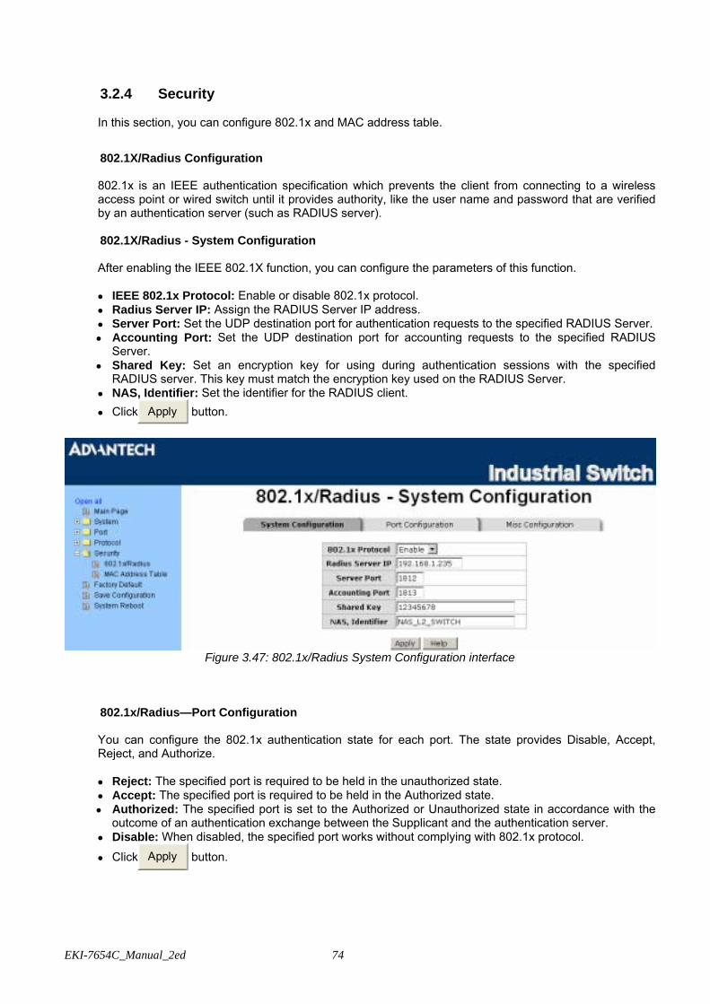
EKI-7654C_Manual_2ed 74
3.2.4 Security
In this section, you can configure 802.1x and MAC address table.
802.1X/Radius Configuration
802.1x is an IEEE authentication specification which prevents the client from connecting to a wireless access point or wired switch until it provides authority, like the user name and password that are verified by an authentication server (such as RADIUS server).
802.1X/Radius - System Configuration
After enabling the IEEE 802.1X function, you can configure the parameters of this function. • IEEE 802.1x Protocol: Enable or disable 802.1x protocol. • Radius Server IP: Assign the RADIUS Server IP address. • Server Port: Set the UDP destination port for authentication requests to the specified RADIUS Server. • Accounting Port: Set the UDP destination port for accounting requests to the specified RADIUS
Server. • Shared Key: Set an encryption key for using during authentication sessions with the specified
RADIUS server. This key must match the encryption key used on the RADIUS Server. • NAS, Identifier: Set the identifier for the RADIUS client. • Click Apply button.
Figure 3.47: 802.1x/Radius System Configuration interface
802.1x/Radius—Port Configuration You can configure the 802.1x authentication state for each port. The state provides Disable, Accept, Reject, and Authorize. • Reject: The specified port is required to be held in the unauthorized state. • Accept: The specified port is required to be held in the Authorized state. • Authorized: The specified port is set to the Authorized or Unauthorized state in accordance with the
outcome of an authentication exchange between the Supplicant and the authentication server. • Disable: When disabled, the specified port works without complying with 802.1x protocol.
• Click Apply button.
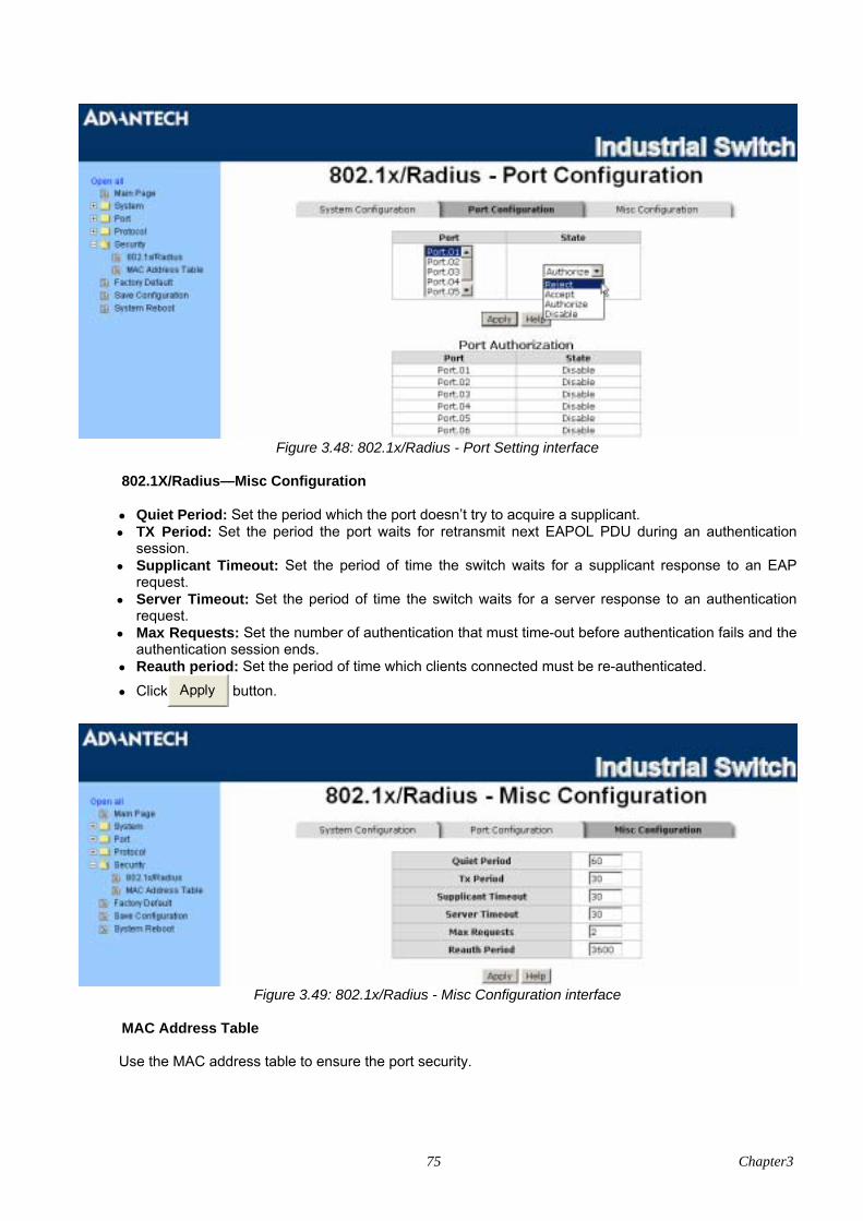
75 Chapter3
Figure 3.48: 802.1x/Radius - Port Setting interface
802.1X/Radius—Misc Configuration • Quiet Period: Set the period which the port doesn’t try to acquire a supplicant. • TX Period: Set the period the port waits for retransmit next EAPOL PDU during an authentication
session. • Supplicant Timeout: Set the period of time the switch waits for a supplicant response to an EAP
request. • Server Timeout: Set the period of time the switch waits for a server response to an authentication
request. • Max Requests: Set the number of authentication that must time-out before authentication fails and the
authentication session ends. • Reauth period: Set the period of time which clients connected must be re-authenticated.
• Click Apply button.
Figure 3.49: 802.1x/Radius - Misc Configuration interface
MAC Address Table Use the MAC address table to ensure the port security.

EKI-7654C_Manual_2ed 76
You can add a static MAC address; it remains in the switch's address table, regardless of whether the device is physically connected to the switch. This saves the switch from having to re-learn a device's MAC address when the disconnected or powered-off device is active on the network again. You can add / modify / delete a static MAC address.
MAC Address Table - Static MAC Address You can add static MAC address in the switch MAC table here. • MAC Address: Enter the MAC address of the port that should permanently forward traffic, regardless
of the device network activity. • Port No.: Pull down the selection menu to select the port number. • Click Add button.
• If you want to delete the MAC address from filtering table, select the MAC address and click Delete button.
Figure 3.50: Static MAC Addresses interface
MAC Address Table - MAC Filtering By filtering MAC address, the switch can easily filter the pre-configured MAC address and reduce the un-safety. You can add and delete filtering MAC address.
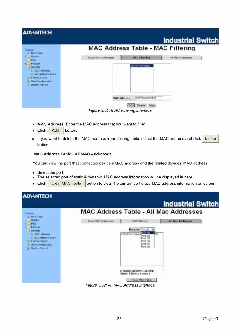
77 Chapter3
Figure 3.51: MAC Filtering interface
• MAC Address: Enter the MAC address that you want to filter. • Click Add button.
• If you want to delete the MAC address from filtering table, select the MAC address and click Delete button.
MAC Address Table - All MAC Addresses
You can view the port that connected device’s MAC address and the related devices’ MAC address. • Select the port. • The selected port of static & dynamic MAC address information will be displayed in here. • Click Clear MAC Table button to clear the current port static MAC address information on screen.
Figure 3.52: All MAC Address interface
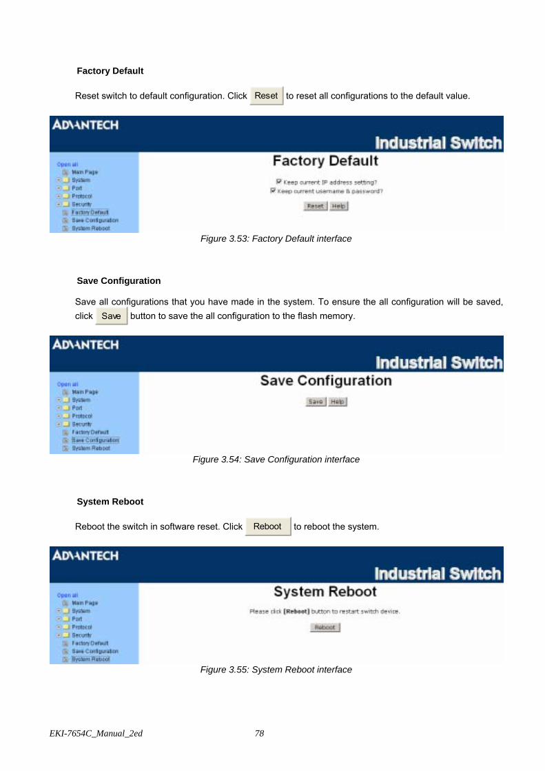
EKI-7654C_Manual_2ed 78
Factory Default Reset switch to default configuration. Click Reset to reset all configurations to the default value.
Figure 3.53: Factory Default interface
Save Configuration Save all configurations that you have made in the system. To ensure the all configuration will be saved, click Save button to save the all configuration to the flash memory.
Figure 3.54: Save Configuration interface
System Reboot Reboot the switch in software reset. Click Reboot to reboot the system.
Figure 3.55: System Reboot interface

79
Troubleshooting
CH
APT
ER

EKI-7654C_Manual_2ed 80
Chapter 4 Troubleshooting Verify that you are using the right power cord/adapter (+12 ~ 48VDC), please don’t use the power adaptor with DC output voltage higher than 48 V, or it will burn this converter down. Select the proper UTP cable to construct the user network. Use unshielded twisted-pair (UTP) or shield twisted-pair (STP) cable for RJ-45 connections: 100Ω Category 3, 4 or 5 cable for 10Mbps connections, 100Ω Category 5 cable for 100Mbps connections, or 100Ω Category 5e/above cable for 1000Mbps connections. Also be sure that the length of any twisted-pair connection does not exceed 100 meters (328 feet). Diagnosing LED Indicators To assist in identifying problems, the switch can be easily monitored through panel indicators, which describe common problems the user may encounter and where the user can find possible solutions. If the power indicator does not light on when the power cord is plugged in, you may have a problem with power cord. Then check for loose power connections, power losses or surges at power outlet. If you still cannot resolve the problem, contact the local dealer for assistance. If the LED indicators are normal and the connected cables are correct but the packets still cannot be transmitted. Please check the user system’s Ethernet devices’ configuration or status.

81
Pin Assignment &
Wiring
APP
END
IX
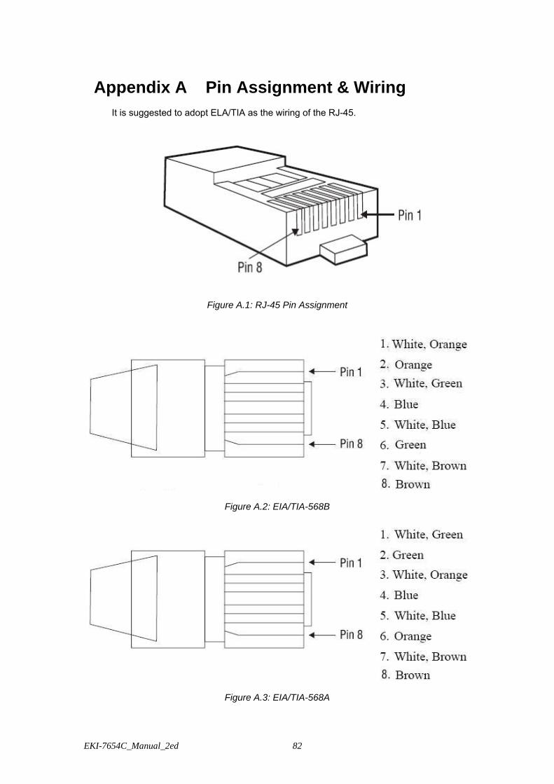
EKI-7654C_Manual_2ed 82
Appendix A Pin Assignment & Wiring It is suggested to adopt ELA/TIA as the wiring of the RJ-45.
Figure A.1: RJ-45 Pin Assignment
Figure A.2: EIA/TIA-568B
Figure A.3: EIA/TIA-568A

83
Figure A.4: DB 9-pin female connector
DB9 Connector RJ-45 Connector NC 1 Orange/White 2 2 Orange 3 3 Green/White NC 4 Blue 5 5 Blue/White NC 6 Green NC 7 Brown/White NC 8 Brown

EKI-7654C_Manual_2ed 84

85
Compatible SFP
Modules
APP
END
IX
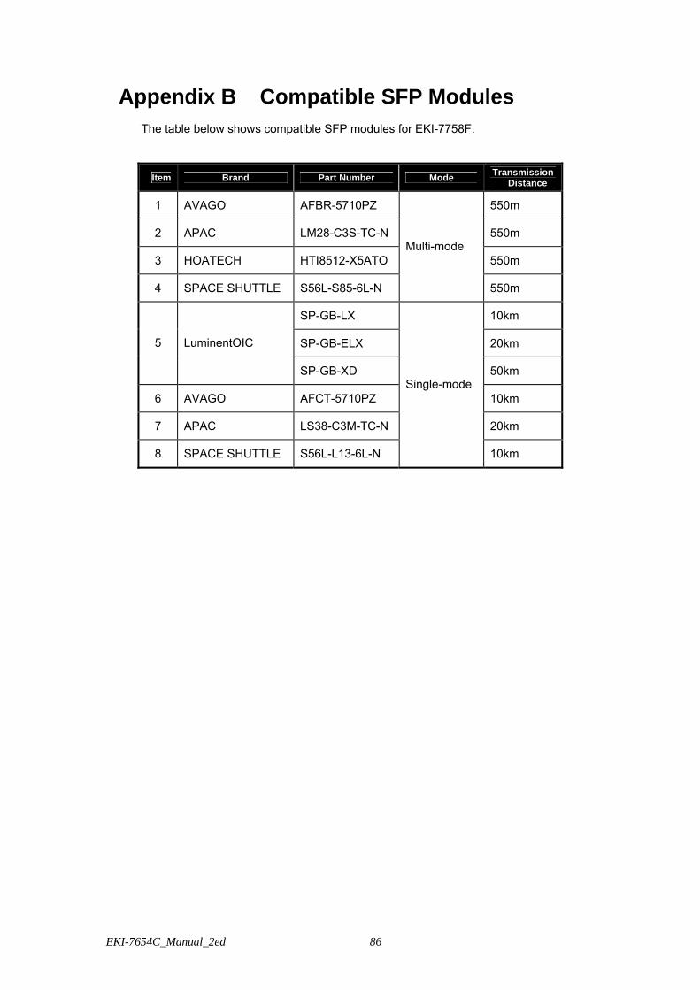
EKI-7654C_Manual_2ed 86
Appendix B Compatible SFP Modules The table below shows compatible SFP modules for EKI-7758F.
Item Brand Part Number Mode Transmission Distance
1 AVAGO AFBR-5710PZ 550m
2 APAC LM28-C3S-TC-N 550m
3 HOATECH HTI8512-X5ATO 550m
4 SPACE SHUTTLE S56L-S85-6L-N
Multi-mode
550m
SP-GB-LX 10km
SP-GB-ELX 20km 5 LuminentOIC
SP-GB-XD 50km
6 AVAGO AFCT-5710PZ 10km
7 APAC LS38-C3M-TC-N 20km
8 SPACE SHUTTLE S56L-L13-6L-N
Single-mode
10km

87
APP
END
IX
X-View
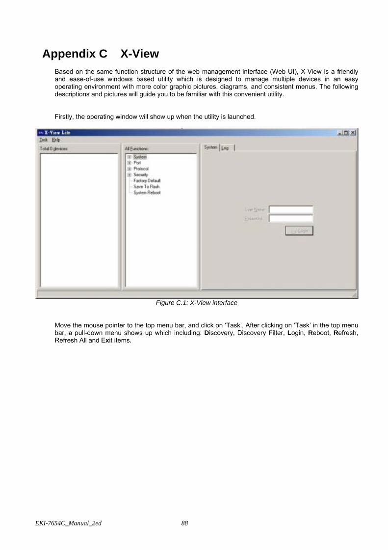
EKI-7654C_Manual_2ed 88
Appendix C X-View
Based on the same function structure of the web management interface (Web UI), X-View is a friendly and ease-of-use windows based utility which is designed to manage multiple devices in an easy operating environment with more color graphic pictures, diagrams, and consistent menus. The following descriptions and pictures will guide you to be familiar with this convenient utility. Firstly, the operating window will show up when the utility is launched.
Figure C.1: X-View interface
Move the mouse pointer to the top menu bar, and click on ‘Task’. After clicking on ‘Task’ in the top menu bar, a pull-down menu shows up which including: Discovery, Discovery Filter, Login, Reboot, Refresh, Refresh All and Exit items.
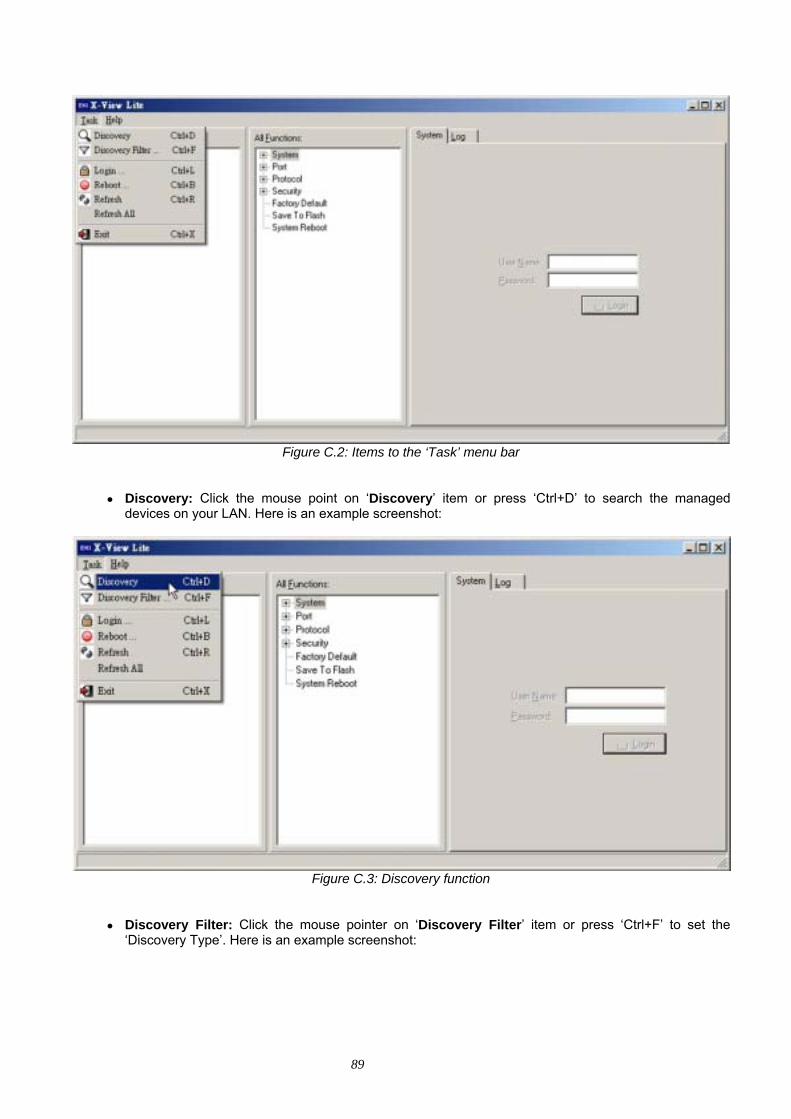
89
Figure C.2: Items to the ‘Task’ menu bar
• Discovery: Click the mouse point on ‘Discovery’ item or press ‘Ctrl+D’ to search the managed devices on your LAN. Here is an example screenshot:
Figure C.3: Discovery function
• Discovery Filter: Click the mouse pointer on ‘Discovery Filter’ item or press ‘Ctrl+F’ to set the ‘Discovery Type’. Here is an example screenshot:
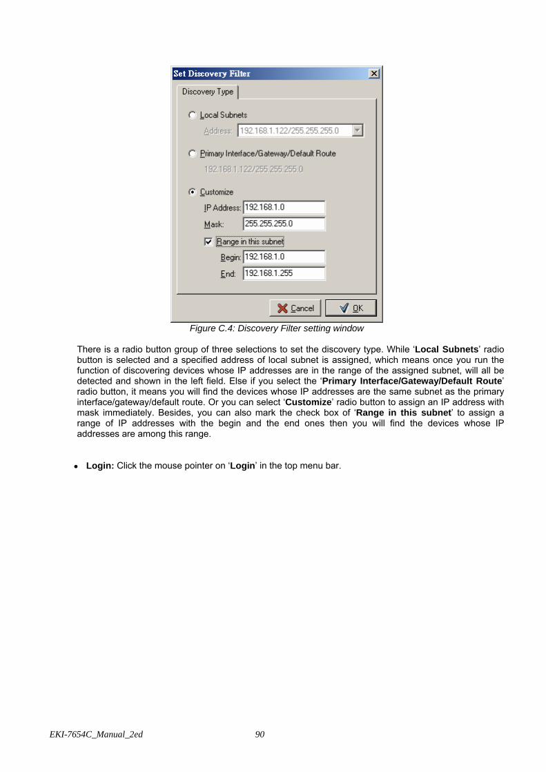
EKI-7654C_Manual_2ed 90
Figure C.4: Discovery Filter setting window
There is a radio button group of three selections to set the discovery type. While ‘Local Subnets’ radio button is selected and a specified address of local subnet is assigned, which means once you run the function of discovering devices whose IP addresses are in the range of the assigned subnet, will all be detected and shown in the left field. Else if you select the ‘Primary Interface/Gateway/Default Route’ radio button, it means you will find the devices whose IP addresses are the same subnet as the primary interface/gateway/default route. Or you can select ‘Customize’ radio button to assign an IP address with mask immediately. Besides, you can also mark the check box of ‘Range in this subnet’ to assign a range of IP addresses with the begin and the end ones then you will find the devices whose IP addresses are among this range. • Login: Click the mouse pointer on ‘Login’ in the top menu bar.

91
Figure C.5: Login interface
Select any one of the devices in the left tree menu field; the login interface (User Name/Password) on the right side will subsequently be available (see the figure below).
Figure C.6: User Name/Password interface
• Reboot: Click the mouse pointer on ‘Reboot’ in the top menu bar.
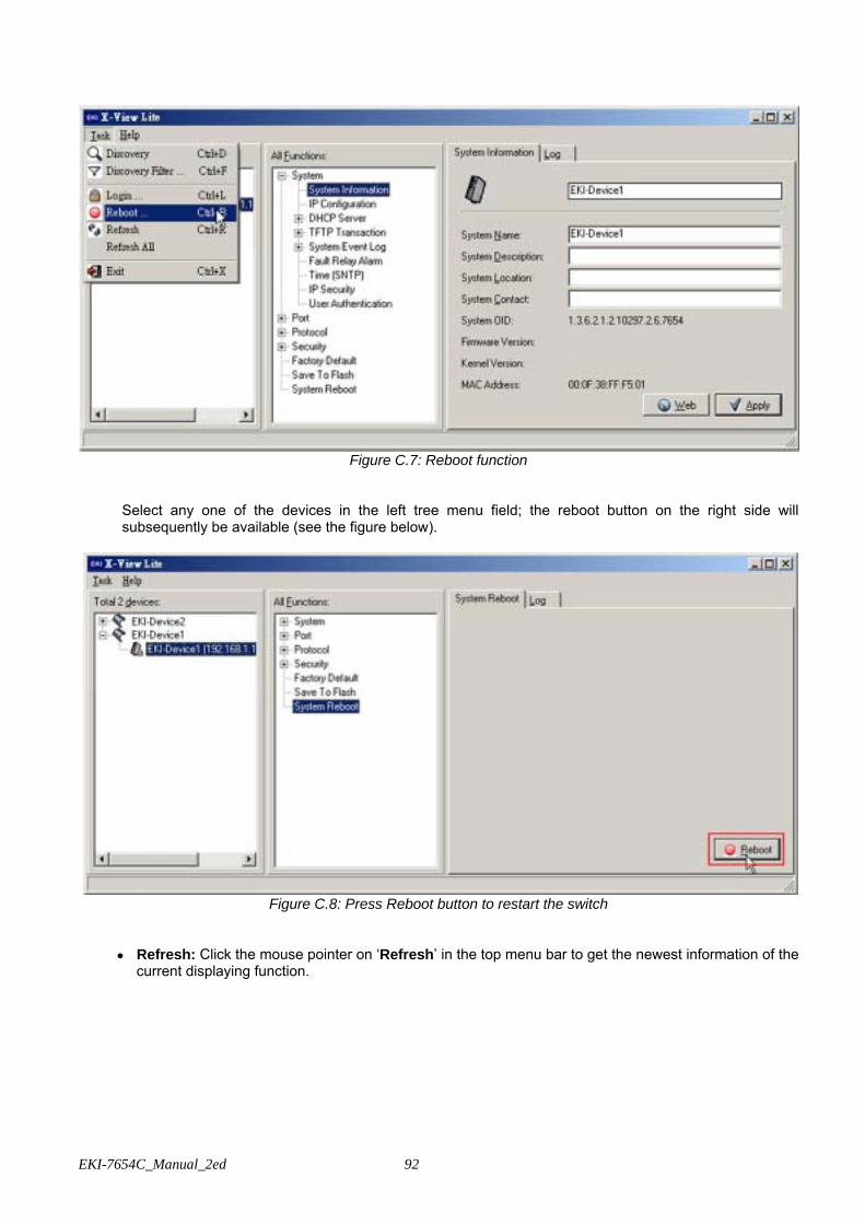
EKI-7654C_Manual_2ed 92
Figure C.7: Reboot function
Select any one of the devices in the left tree menu field; the reboot button on the right side will subsequently be available (see the figure below).
Figure C.8: Press Reboot button to restart the switch
• Refresh: Click the mouse pointer on ‘Refresh’ in the top menu bar to get the newest information of the current displaying function.
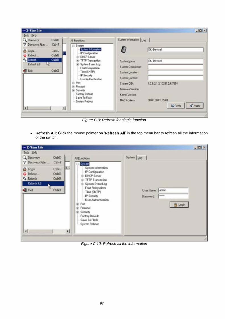
93
Figure C.9: Refresh for single function
• Refresh All: Click the mouse pointer on ‘Refresh All’ in the top menu bar to refresh all the information of the switch.
Figure C.10: Refresh all the information
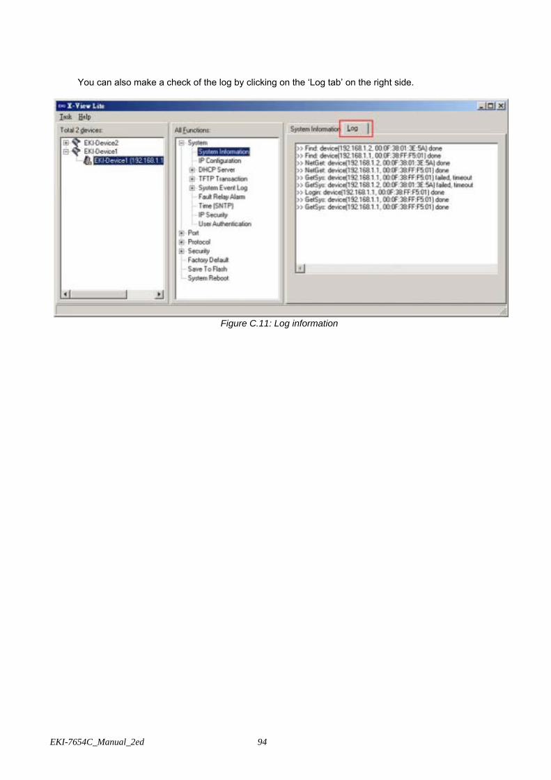
EKI-7654C_Manual_2ed 94
You can also make a check of the log by clicking on the ‘Log tab’ on the right side.
Figure C.11: Log information

95
The items in the top menu bar have been introduced. Subsequently, we will go through how to manage the devices via X-View interface.
C.1 System
C.1.1 System Information
Assign the system name, location and view the system information. • System Name: Assign the name of the switch. The maximum length is 64 bytes. • System Description: Describes the switch. • System Location: Assign the switch physical location. The maximum length is 64 bytes. • System Contact: Enter the name of contact person or organization. • System OID: Displays the strings of numbers of the system OID. • Firmware Version: Displays the switch’s firmware version. • Kernel Version: Displays the kernel software version. • MAC Address: Displays the unique hardware address assigned by manufacturer (default). • Click Web button to run Internet Explorer for web interface management. • Click Apply button to have the setting taken effective.
Warning Don’t set “0” for the first segment of the subnet mask and default gateway (000.xxx.xxx.xxx).
Refresh the web screen if the web could not be displayed while you change the setting.
Figure C.12: System information
C.1.2 IP Configuration
User can configure the IP Settings and DHCP client function here. • DHCP Client: Pull down the Method selection menu item and select the DHCP option to enable the
DHCP client function. When DHCP client function is enabled, the industrial switch will be assigned an IP address from the network DHCP server. The default IP address will be replaced by the assigned IP
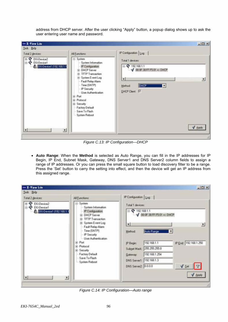
EKI-7654C_Manual_2ed 96
address from DHCP server. After the user clicking “Apply” button, a popup dialog shows up to ask the user entering user name and password.
Figure C.13: IP Configuration—DHCP
• Auto Range: When the Method is selected as Auto Range, you can fill in the IP addresses for IP Begin, IP End, Subnet Mask, Gateway, DNS Server1 and DNS Server2 column fields to assign a range of IP addresses. Or you can press the small square button to load discovery filter to be a range. Press the ‘Set’ button to carry the setting into effect, and then the device will get an IP address from this assigned range.
Figure C.14: IP Configuration—Auto range

97
• Manual: When the Method is selected as Manual, you can enter the IP configuration into the related column fields directly to assign or change the IP configuration. Press the ‘Set’ button to carry the setting into effect.
Figure C.15: IP Configuration—Manual
C.1.3 DHCP Server
The system provides the DHCP server function. Having enabled the DHCP server function, the switch system can be a DHCP server.
• DHCP Server: Enable or Disable the DHCP Server function. Enable—the switch will be the DHCP
server on your local network. • Low IP Address: Type in an IP address. Low IP address is the beginning of the dynamic IP range. For
example, dynamic IP is in the range between 192.168.1.100 ~ 192.168.1.200. In contrast, 192.168.1.100 is the Low IP address.
• High IP Address: Type in an IP address. High IP address is the end of the dynamic IP range. For example, dynamic IP is in the range between 192.168.1.100 ~ 192.168.1.200. In contrast, 192.168.1.200 is the High IP address.
• Subnet Mask: Type in the subnet mask of the IP configuration. • Gateway: Type in the IP address of the gateway in your network. • DNS: Type in the Domain Name Server IP Address in your network. • Lease Time (sec): It is the time period that system will reset the dynamic IP assignment to ensure the
dynamic IP will not been occupied for a long time or the server doesn’t know that the dynamic IP is idle.

EKI-7654C_Manual_2ed 98
Figure C.16: DHCP Server interface
Client Entries
When the DHCP server function is active, the system will collect the DHCP client information and displays it here.
Figure C.17: DHCP Server—Client Entries
Port and IP Binding
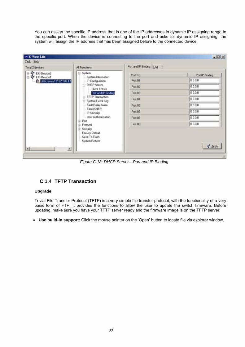
99
You can assign the specific IP address that is one of the IP addresses in dynamic IP assigning range to the specific port. When the device is connecting to the port and asks for dynamic IP assigning, the system will assign the IP address that has been assigned before to the connected device.
Figure C.18: DHCP Server—Port and IP Binding
C.1.4 TFTP Transaction
Upgrade
Trivial File Transfer Protocol (TFTP) is a very simple file transfer protocol, with the functionality of a very basic form of FTP. It provides the functions to allow the user to update the switch firmware. Before updating, make sure you have your TFTP server ready and the firmware image is on the TFTP server.
• Use build-in support: Click the mouse pointer on the ‘Open’ button to locate file via explorer window.
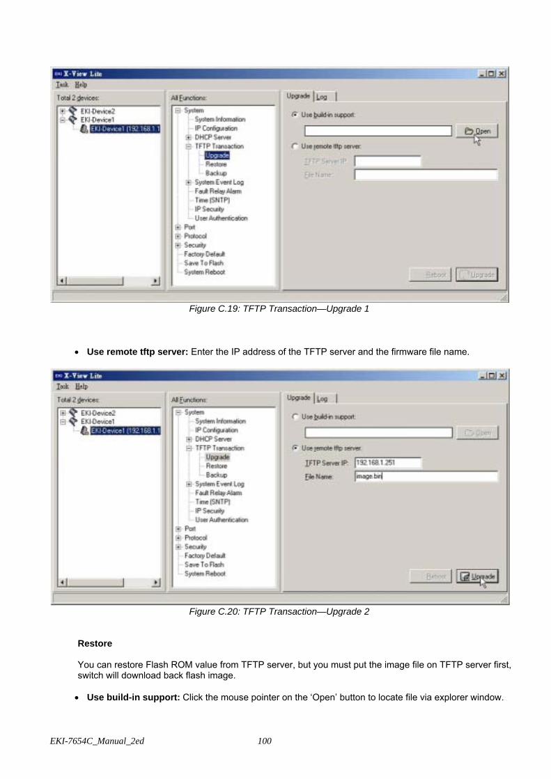
EKI-7654C_Manual_2ed 100
Figure C.19: TFTP Transaction—Upgrade 1
• Use remote tftp server: Enter the IP address of the TFTP server and the firmware file name.
Figure C.20: TFTP Transaction—Upgrade 2
Restore
You can restore Flash ROM value from TFTP server, but you must put the image file on TFTP server first, switch will download back flash image.
• Use build-in support: Click the mouse pointer on the ‘Open’ button to locate file via explorer window.
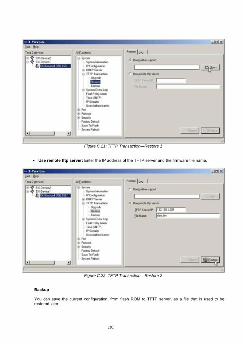
101
Figure C.21: TFTP Transaction—Restore 1
• Use remote tftp server: Enter the IP address of the TFTP server and the firmware file name.
Figure C.22: TFTP Transaction—Restore 2
Backup
You can save the current configuration, from flash ROM to TFTP server, as a file that is used to be restored later.

EKI-7654C_Manual_2ed 102
• Use build-in support: Click the mouse pointer on the ‘Save’ button to locate a path via explorer window for saving the backup file.
Figure C.23: TFTP Transaction—Backup 1
• Use remote tftp server: Enter the IP address of the TFTP server and the firmware file name.
Figure C.24: TFTP Transaction—Backup 2
C.1.5 System Event Log
Syslog Configuration
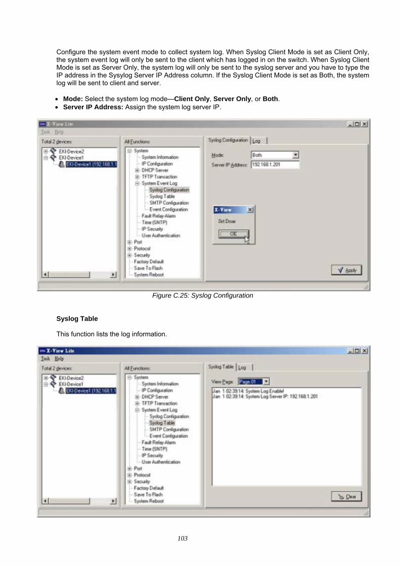
103
Configure the system event mode to collect system log. When Syslog Client Mode is set as Client Only, the system event log will only be sent to the client which has logged in on the switch. When Syslog Client Mode is set as Server Only, the system log will only be sent to the syslog server and you have to type the IP address in the Sysylog Server IP Address column. If the Syslog Client Mode is set as Both, the system log will be sent to client and server. • Mode: Select the system log mode—Client Only, Server Only, or Both. • Server IP Address: Assign the system log server IP.
Figure C.25: Syslog Configuration
Syslog Table
This function lists the log information.
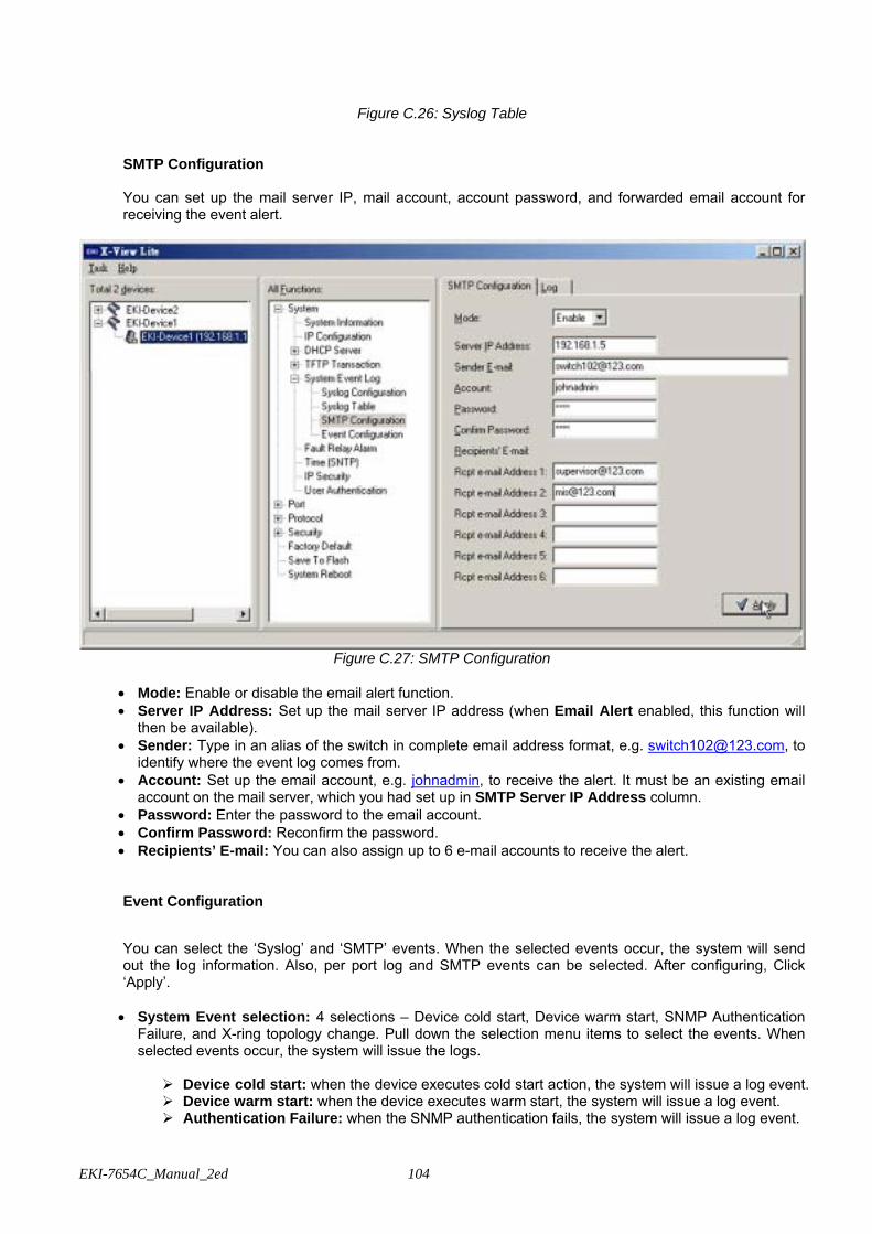
EKI-7654C_Manual_2ed 104
Figure C.26: Syslog Table
SMTP Configuration
You can set up the mail server IP, mail account, account password, and forwarded email account for receiving the event alert.
Figure C.27: SMTP Configuration
• Mode: Enable or disable the email alert function. • Server IP Address: Set up the mail server IP address (when Email Alert enabled, this function will
then be available). • Sender: Type in an alias of the switch in complete email address format, e.g. [email protected], to
identify where the event log comes from. • Account: Set up the email account, e.g. johnadmin, to receive the alert. It must be an existing email
account on the mail server, which you had set up in SMTP Server IP Address column. • Password: Enter the password to the email account. • Confirm Password: Reconfirm the password. • Recipients’ E-mail: You can also assign up to 6 e-mail accounts to receive the alert.
Event Configuration
You can select the ‘Syslog’ and ‘SMTP’ events. When the selected events occur, the system will send out the log information. Also, per port log and SMTP events can be selected. After configuring, Click ‘Apply’. • System Event selection: 4 selections – Device cold start, Device warm start, SNMP Authentication
Failure, and X-ring topology change. Pull down the selection menu items to select the events. When selected events occur, the system will issue the logs.
Device cold start: when the device executes cold start action, the system will issue a log event. Device warm start: when the device executes warm start, the system will issue a log event. Authentication Failure: when the SNMP authentication fails, the system will issue a log event.
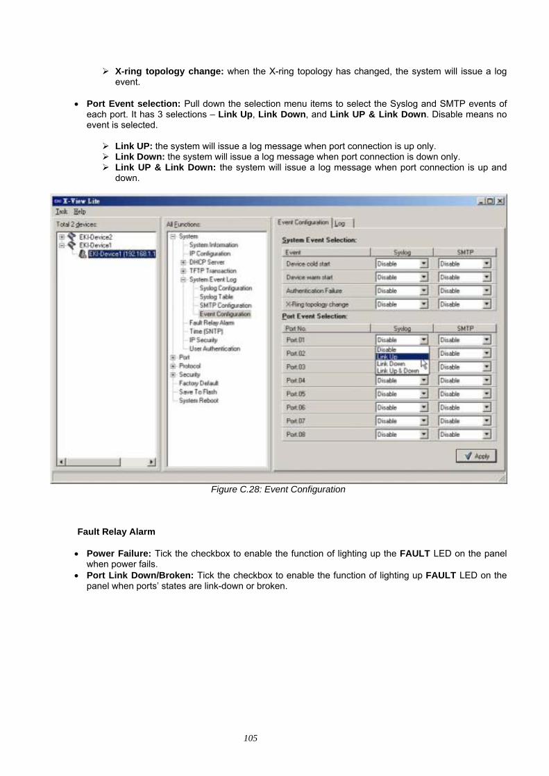
105
X-ring topology change: when the X-ring topology has changed, the system will issue a log event.
• Port Event selection: Pull down the selection menu items to select the Syslog and SMTP events of
each port. It has 3 selections – Link Up, Link Down, and Link UP & Link Down. Disable means no event is selected.
Link UP: the system will issue a log message when port connection is up only. Link Down: the system will issue a log message when port connection is down only. Link UP & Link Down: the system will issue a log message when port connection is up and
down.
Figure C.28: Event Configuration
Fault Relay Alarm • Power Failure: Tick the checkbox to enable the function of lighting up the FAULT LED on the panel
when power fails. • Port Link Down/Broken: Tick the checkbox to enable the function of lighting up FAULT LED on the
panel when ports’ states are link-down or broken.
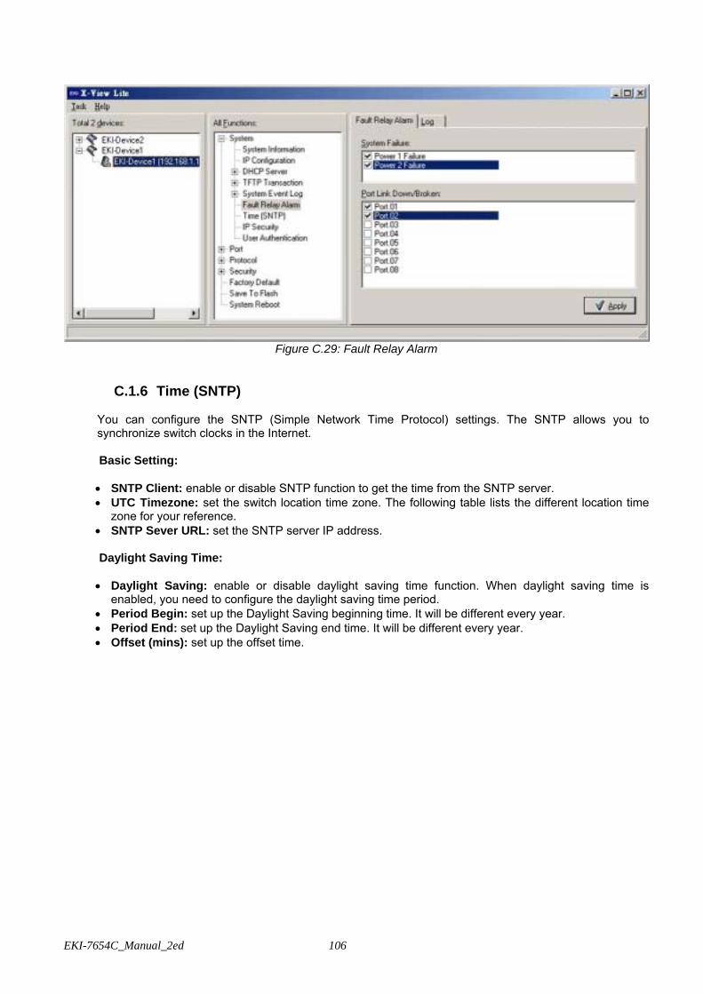
EKI-7654C_Manual_2ed 106
Figure C.29: Fault Relay Alarm
C.1.6 Time (SNTP) You can configure the SNTP (Simple Network Time Protocol) settings. The SNTP allows you to synchronize switch clocks in the Internet.
Basic Setting:
• SNTP Client: enable or disable SNTP function to get the time from the SNTP server. • UTC Timezone: set the switch location time zone. The following table lists the different location time
zone for your reference. • SNTP Sever URL: set the SNTP server IP address.
Daylight Saving Time:
• Daylight Saving: enable or disable daylight saving time function. When daylight saving time is
enabled, you need to configure the daylight saving time period. • Period Begin: set up the Daylight Saving beginning time. It will be different every year. • Period End: set up the Daylight Saving end time. It will be different every year. • Offset (mins): set up the offset time.
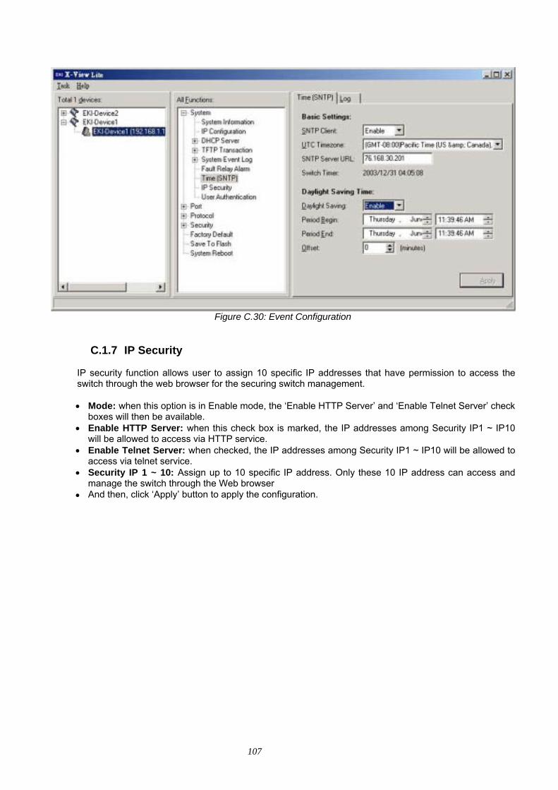
107
Figure C.30: Event Configuration
C.1.7 IP Security IP security function allows user to assign 10 specific IP addresses that have permission to access the switch through the web browser for the securing switch management.
• Mode: when this option is in Enable mode, the ‘Enable HTTP Server’ and ‘Enable Telnet Server’ check
boxes will then be available. • Enable HTTP Server: when this check box is marked, the IP addresses among Security IP1 ~ IP10
will be allowed to access via HTTP service. • Enable Telnet Server: when checked, the IP addresses among Security IP1 ~ IP10 will be allowed to
access via telnet service. • Security IP 1 ~ 10: Assign up to 10 specific IP address. Only these 10 IP address can access and
manage the switch through the Web browser • And then, click ‘Apply’ button to apply the configuration.
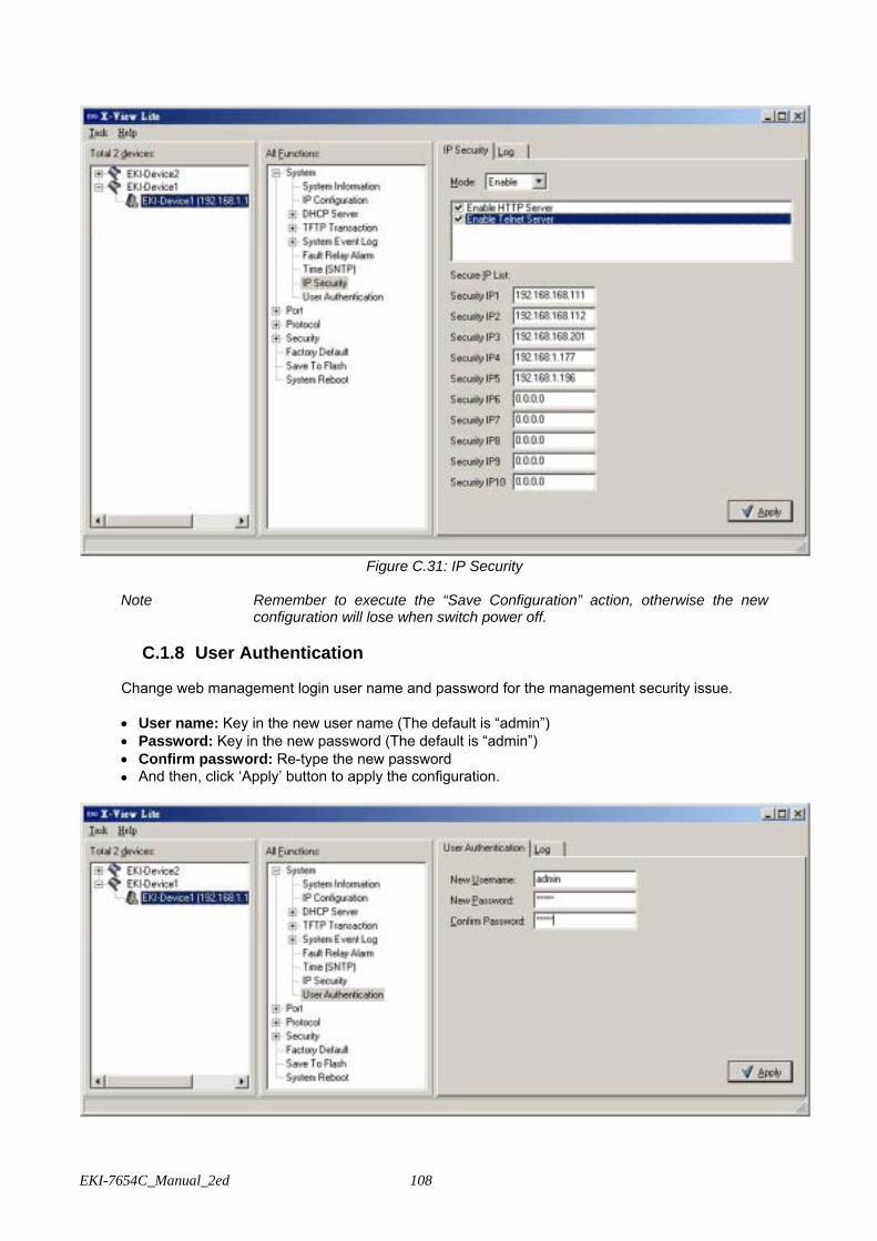
EKI-7654C_Manual_2ed 108
Figure C.31: IP Security
Note Remember to execute the “Save Configuration” action, otherwise the new
configuration will lose when switch power off.
C.1.8 User Authentication
Change web management login user name and password for the management security issue.
• User name: Key in the new user name (The default is “admin”) • Password: Key in the new password (The default is “admin”) • Confirm password: Re-type the new password • And then, click ‘Apply’ button to apply the configuration.
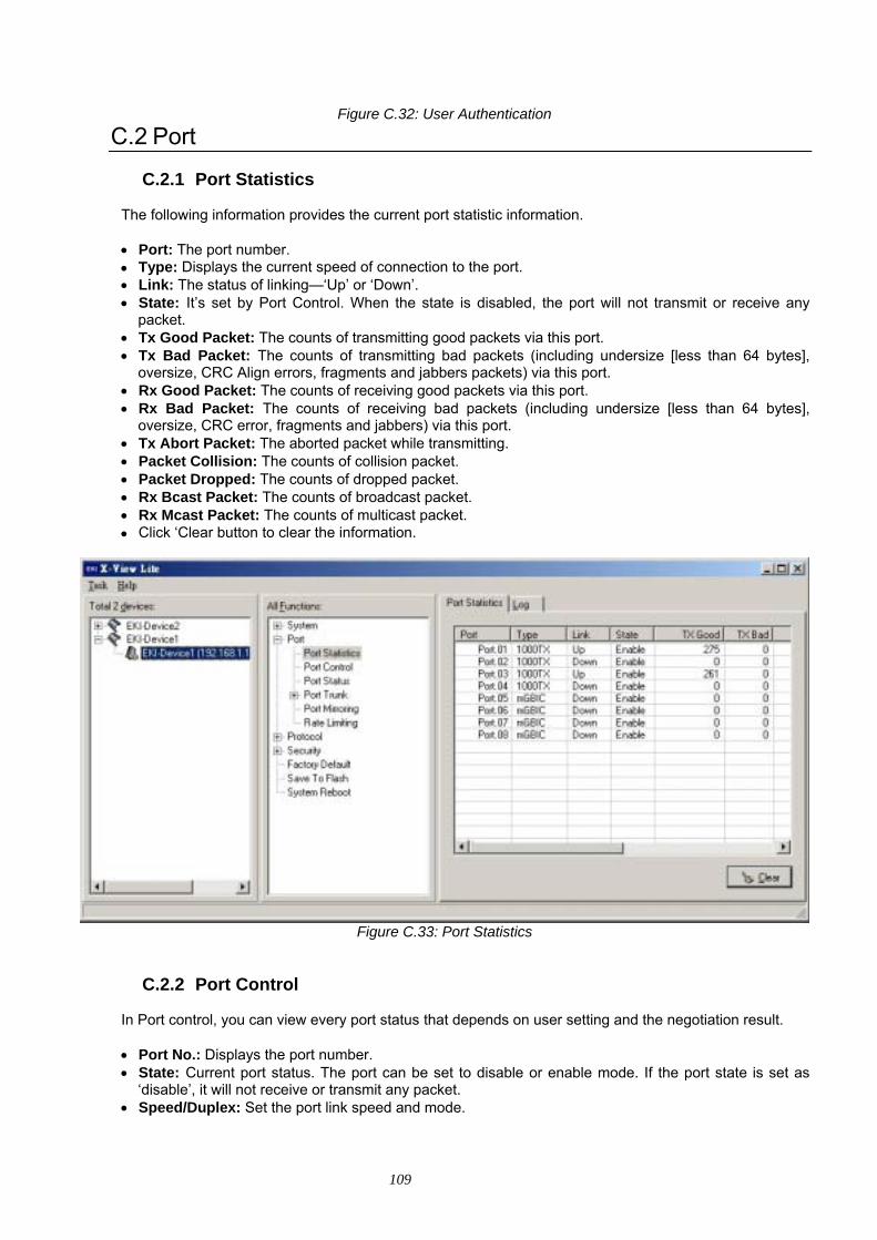
109
Figure C.32: User Authentication
C.2 Port
C.2.1 Port Statistics
The following information provides the current port statistic information. • Port: The port number. • Type: Displays the current speed of connection to the port. • Link: The status of linking—‘Up’ or ‘Down’. • State: It’s set by Port Control. When the state is disabled, the port will not transmit or receive any
packet. • Tx Good Packet: The counts of transmitting good packets via this port. • Tx Bad Packet: The counts of transmitting bad packets (including undersize [less than 64 bytes],
oversize, CRC Align errors, fragments and jabbers packets) via this port. • Rx Good Packet: The counts of receiving good packets via this port. • Rx Bad Packet: The counts of receiving bad packets (including undersize [less than 64 bytes],
oversize, CRC error, fragments and jabbers) via this port. • Tx Abort Packet: The aborted packet while transmitting. • Packet Collision: The counts of collision packet. • Packet Dropped: The counts of dropped packet. • Rx Bcast Packet: The counts of broadcast packet. • Rx Mcast Packet: The counts of multicast packet. • Click ‘Clear button to clear the information.
Figure C.33: Port Statistics
C.2.2 Port Control In Port control, you can view every port status that depends on user setting and the negotiation result.
• Port No.: Displays the port number. • State: Current port status. The port can be set to disable or enable mode. If the port state is set as
‘disable’, it will not receive or transmit any packet. • Speed/Duplex: Set the port link speed and mode.

EKI-7654C_Manual_2ed 110
• Flow Control: Set flow control function as Enable or Disable. When enabled, once the device exceed the input data rate of another device as a result the receiving device will send a PAUSE frame which halts the transmission of the sender for a specified period of time. When disabled, the receiving device will drop the packet if too much to process.
• Security: Once the Security selection is set as ‘On’, any access from the device which connects to this port will be blocked unless the MAC address of the device is included in the static MAC address table. See the segment of Static MAC Table.
• Click ‘Apply’ button to apply the configuration.
Figure C.34: Port Control
C.2.3 Port Status
In Port Status, you can view every port status that depends on user setting and the negotiation result.
Figure C.35: Port Status
• Port No.: Displays the port number.
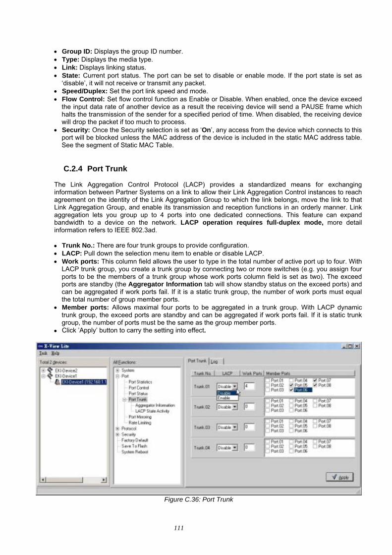
111
• Group ID: Displays the group ID number. • Type: Displays the media type. • Link: Displays linking status. • State: Current port status. The port can be set to disable or enable mode. If the port state is set as
‘disable’, it will not receive or transmit any packet. • Speed/Duplex: Set the port link speed and mode. • Flow Control: Set flow control function as Enable or Disable. When enabled, once the device exceed
the input data rate of another device as a result the receiving device will send a PAUSE frame which halts the transmission of the sender for a specified period of time. When disabled, the receiving device will drop the packet if too much to process.
• Security: Once the Security selection is set as ‘On’, any access from the device which connects to this port will be blocked unless the MAC address of the device is included in the static MAC address table. See the segment of Static MAC Table.
C.2.4 Port Trunk
The Link Aggregation Control Protocol (LACP) provides a standardized means for exchanging information between Partner Systems on a link to allow their Link Aggregation Control instances to reach agreement on the identity of the Link Aggregation Group to which the link belongs, move the link to that Link Aggregation Group, and enable its transmission and reception functions in an orderly manner. Link aggregation lets you group up to 4 ports into one dedicated connections. This feature can expand bandwidth to a device on the network. LACP operation requires full-duplex mode, more detail information refers to IEEE 802.3ad.
• Trunk No.: There are four trunk groups to provide configuration. • LACP: Pull down the selection menu item to enable or disable LACP. • Work ports: This column field allows the user to type in the total number of active port up to four. With
LACP trunk group, you create a trunk group by connecting two or more switches (e.g. you assign four ports to be the members of a trunk group whose work ports column field is set as two). The exceed ports are standby (the Aggregator Information tab will show standby status on the exceed ports) and can be aggregated if work ports fail. If it is a static trunk group, the number of work ports must equal the total number of group member ports.
• Member ports: Allows maximal four ports to be aggregated in a trunk group. With LACP dynamic trunk group, the exceed ports are standby and can be aggregated if work ports fail. If it is static trunk group, the number of ports must be the same as the group member ports.
• Click ’Apply’ button to carry the setting into effect.
Figure C.36: Port Trunk
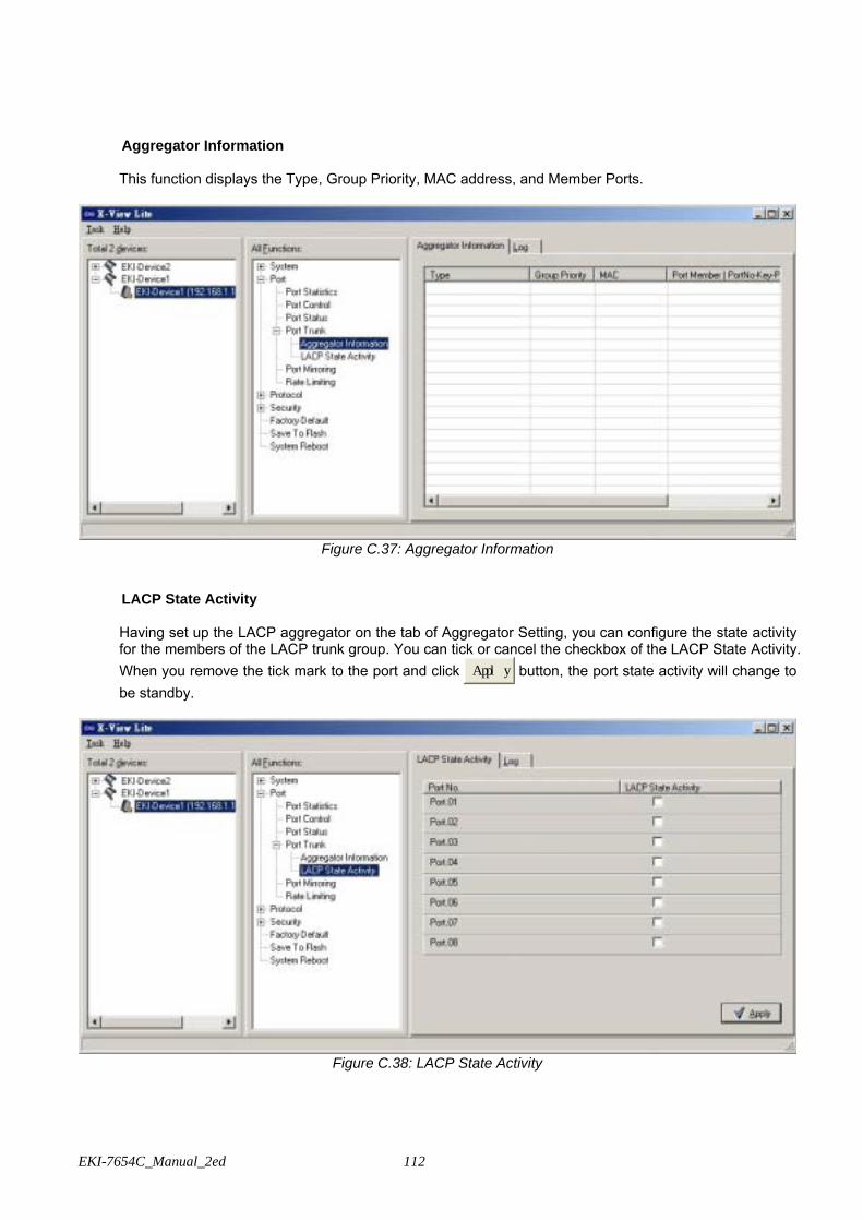
EKI-7654C_Manual_2ed 112
Aggregator Information
This function displays the Type, Group Priority, MAC address, and Member Ports.
Figure C.37: Aggregator Information
LACP State Activity
Having set up the LACP aggregator on the tab of Aggregator Setting, you can configure the state activity for the members of the LACP trunk group. You can tick or cancel the checkbox of the LACP State Activity. When you remove the tick mark to the port and click Apply button, the port state activity will change to be standby.
Figure C.38: LACP State Activity

113
C.2.5 Port Mirroring
The Port mirroring is a method for monitor traffic in switched networks. Traffic through ports can be monitored by one specific port. That means traffic goes in or out monitored (source) ports will be duplicated into mirror (destination) port.
• Rx Destination Port: There is only one port can be selected to be destination (mirror) port for
monitoring RX traffic which come from source port. User can connect mirror port to LAN analyzer or Netxray.
• Tx Destination Port: There is only one port can be selected to be destination (mirror) port for monitoring TX traffic which come from source port. User can connect mirror port to LAN analyzer or Netxray.
• Tick the check boxes to monitor source receiving or transmitting packets of each port. And then, click ‘Clear’ button to clear the marks or click ‘Apply’ button to carry the setting into effect.
Figure C.39: Port Mirroring
C.2.6 Rate Limiting Here you can set up every port’s frame limitation type and bandwidth rate.
• Ingress Limit Frame type: Select the frame type you want to filter. The frame types have 4 options for
selecting: All, Broadcast/Multicast/Flooded Unicast, Broadcast/Multicast, and Broadcast only. The four frame type options are for ingress frames limitation. The egress rate only supports ‘All’ type.
All ports support port ingress and egress rate control. For example, assume port 1 is 10Mbps; the user can set the effective egress rate of port 1 as 1Mbps, ingress rate 500Kbps. The switch performs the ingress rate by packet counter to meet the specified rate
• Ingress: Enter the port effective ingress rate (The default value is “0”) • Egress: Enter the port effective egress rate (The default value is “0”) • And then, click Apply to make the settings taken effect.
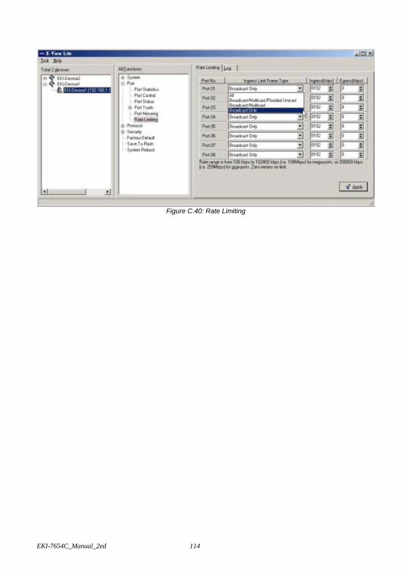
EKI-7654C_Manual_2ed 114
Figure C.40: Rate Limiting

115
C.3 Protocol
C.3.1 VLAN
User can set the layer 2 protocol setting via this interface.
VLAN configuration A Virtual LAN (VLAN) is a logical network grouping that limits the broadcast domain, which would allow you to isolate network traffic, so only the members of the same VLAN will receive traffic from the ones of the same VLAN. Basically, creating a VLAN from a switch is logically equivalent of reconnecting a group of network devices to another Layer 2 switch. However, all the network devices are still plugged into the same switch physically. The switch supports Port-based and 802.1Q (tagged-based) VLAN.
Figure C.41: VLAN Configuration
802.1Q VLAN Tagged-based VLAN is an IEEE 802.1Q specification standard. Therefore, it is possible to create a VLAN across devices from different switch venders. IEEE 802.1Q VLAN uses a technique to insert a “tag” into the Ethernet frames. Tag contains a VLAN Identifier (VID) that indicates the VLAN numbers. You can create Tag-based VLAN, and enable or disable GVRP protocol. There are 256 VLAN groups to provide configure. Enable 802.1Q VLAN, the all ports on the switch belong to default VLAN, VID is 1. The default VLAN can’t be deleting. GVRP allows automatic VLAN configuration between the switch and nodes. If the switch is connected to a device with GVRP enabled, you can send a GVRP request using the VID of a VLAN defined on the switch; the switch will automatically add that device to the existing VLAN.
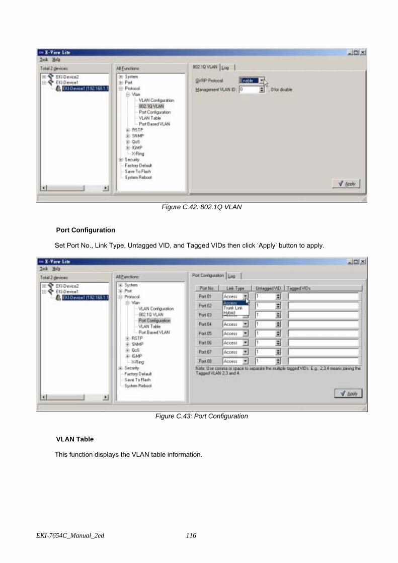
EKI-7654C_Manual_2ed 116
Figure C.42: 802.1Q VLAN
Port Configuration Set Port No., Link Type, Untagged VID, and Tagged VIDs then click ‘Apply’ button to apply.
Figure C.43: Port Configuration
VLAN Table This function displays the VLAN table information.
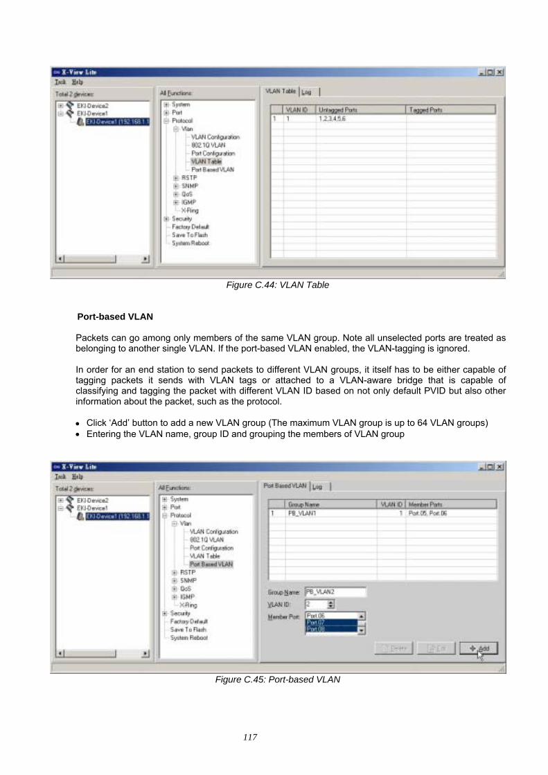
117
Figure C.44: VLAN Table
Port-based VLAN
Packets can go among only members of the same VLAN group. Note all unselected ports are treated as belonging to another single VLAN. If the port-based VLAN enabled, the VLAN-tagging is ignored. In order for an end station to send packets to different VLAN groups, it itself has to be either capable of tagging packets it sends with VLAN tags or attached to a VLAN-aware bridge that is capable of classifying and tagging the packet with different VLAN ID based on not only default PVID but also other information about the packet, such as the protocol.
• Click ‘Add’ button to add a new VLAN group (The maximum VLAN group is up to 64 VLAN groups) • Entering the VLAN name, group ID and grouping the members of VLAN group
Figure C.45: Port-based VLAN

EKI-7654C_Manual_2ed 118
C.3.2 Rapid Spanning Tree
The Rapid Spanning Tree Protocol (RSTP) is an evolution of the Spanning Tree Protocol and provides for faster spanning tree convergence after a topology change. The system also supports STP and the system will auto detect the connected device that is running STP or RSTP protocol.
• User can view spanning tree information about the Root Bridge. • User can modify RSTP state. After modification, click ‘Apply’ button.
Bridge Configuration
• RSTP mode: User must enable or disable RSTP function before configuring the related parameters • Priority (0-61440): A value used to identify the root bridge. The bridge with the lowest value has the
highest priority and is selected as the root. If the value changes, the user must reboot the switch. The value must be multiple of 4096 according to the protocol standard rule.
• Max Age (6-40): The number of seconds a bridge waits without receiving Spanning Tree Protocol configuration messages before attempting a reconfiguration. Enter a value between 6 through 40.
• Hello Time (1-10): The time that controls switch sends out the BPDU packet to check RSTP current status. Enter a value between 1 through 10.
• Forward Delay Time (4-30): The number of seconds a port waits before changing from its Rapid Spanning-Tree Protocol learning and listening states to the forwarding state. Enter a value between 4 through 30.
RSTP - Port Configuration
You can configure path cost and priority of every port. • Port No.: Displays the port number. • Path Cost: The cost of the path to the other bridge from this transmitting bridge at the specified port.
Enter a number 1 through 200,000,000. • Priority: Decide which port should be blocked by priority in LAN. Enter a number 0 through 240. The
value of priority must be the multiple of 16. • Admin P2P: Some of the rapid state transactions that are possible within RSTP are dependent upon
whether the port concerned can only be connected to exactly one other bridge (i.e. it is served by a point-to-point LAN segment), or can be connected to two or more bridges (i.e. it is served by a shared medium LAN segment). This function allows the P2P status of the link to be manipulated administratively. True is P2P enabling. False is P2P disabling.
• Admin Edge: The port directly connected to end stations cannot create bridging loop in the network. To configure the port as an edge port, set the port to “True” status.
• Admin Non STP: The port includes the STP mathematic calculation. True is not including STP mathematic calculation. False is including the STP mathematic calculation.
• Click ’Apply’.
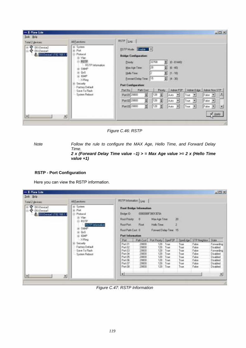
119
Figure C.46: RSTP
Note Follow the rule to configure the MAX Age, Hello Time, and Forward Delay
Time. 2 x (Forward Delay Time value –1) > = Max Age value >= 2 x (Hello Time
value +1)
RSTP - Port Configuration
Here you can view the RSTP information.
Figure C.47: RSTP Information

EKI-7654C_Manual_2ed 120
C.3.3 SNMP
Simple Network Management Protocol (SNMP) is the protocol developed to manage nodes (servers, workstations, routers, switches and hubs etc.) on an IP network. SNMP enables network administrators to manage network performance, find and solve network problems, and plan for network growth. Network management systems learn of problems by receiving traps or change notices from network devices implementing SNMP. Agent Version Select the SNMP version that you want to use it. And then click ‘Apply’ to switch to the selected SNMP version mode.
Figure C.48: SNMP
Community Strings
Figure C.49: Community Strings
You can define new community string set and remove unwanted community string.
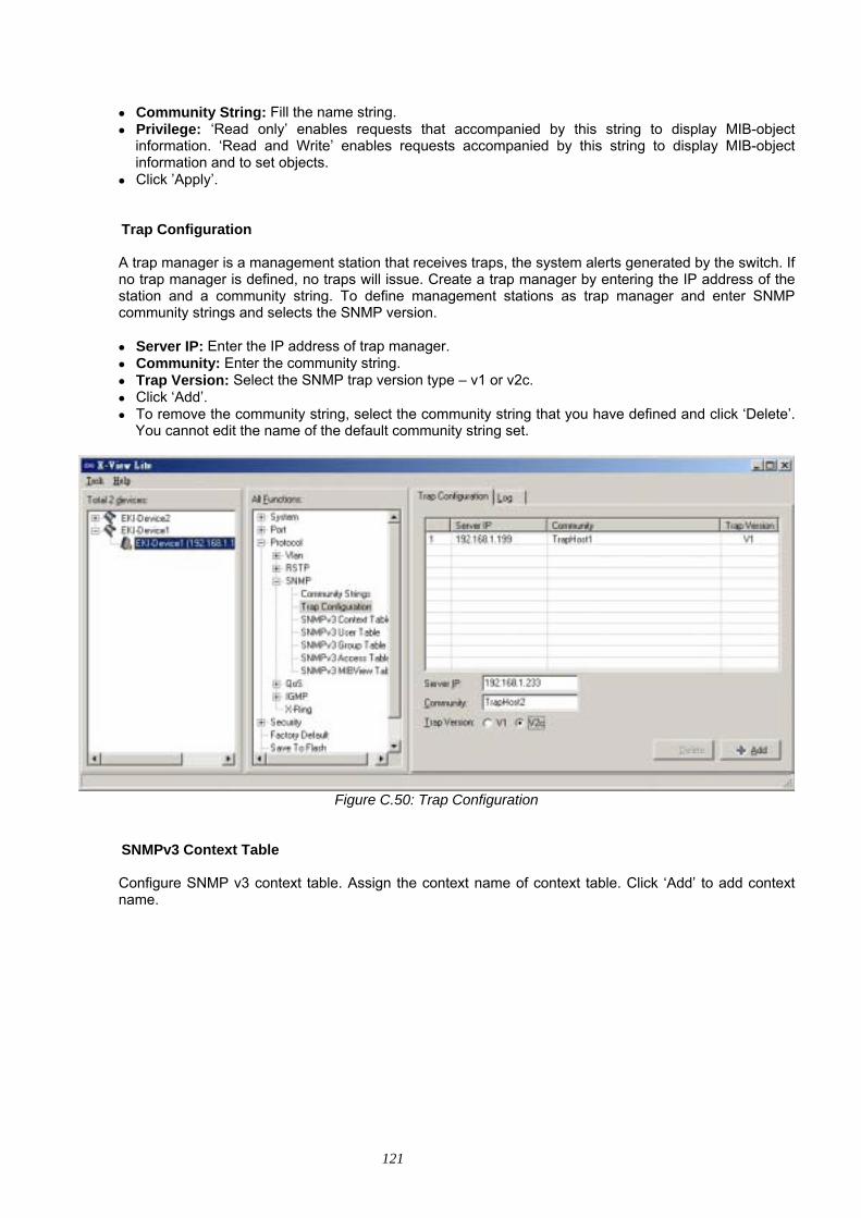
121
• Community String: Fill the name string. • Privilege: ‘Read only’ enables requests that accompanied by this string to display MIB-object
information. ‘Read and Write’ enables requests accompanied by this string to display MIB-object information and to set objects.
• Click ’Apply’.
Trap Configuration A trap manager is a management station that receives traps, the system alerts generated by the switch. If no trap manager is defined, no traps will issue. Create a trap manager by entering the IP address of the station and a community string. To define management stations as trap manager and enter SNMP community strings and selects the SNMP version.
• Server IP: Enter the IP address of trap manager. • Community: Enter the community string. • Trap Version: Select the SNMP trap version type – v1 or v2c. • Click ‘Add’. • To remove the community string, select the community string that you have defined and click ‘Delete’.
You cannot edit the name of the default community string set.
Figure C.50: Trap Configuration
SNMPv3 Context Table Configure SNMP v3 context table. Assign the context name of context table. Click ‘Add’ to add context name.
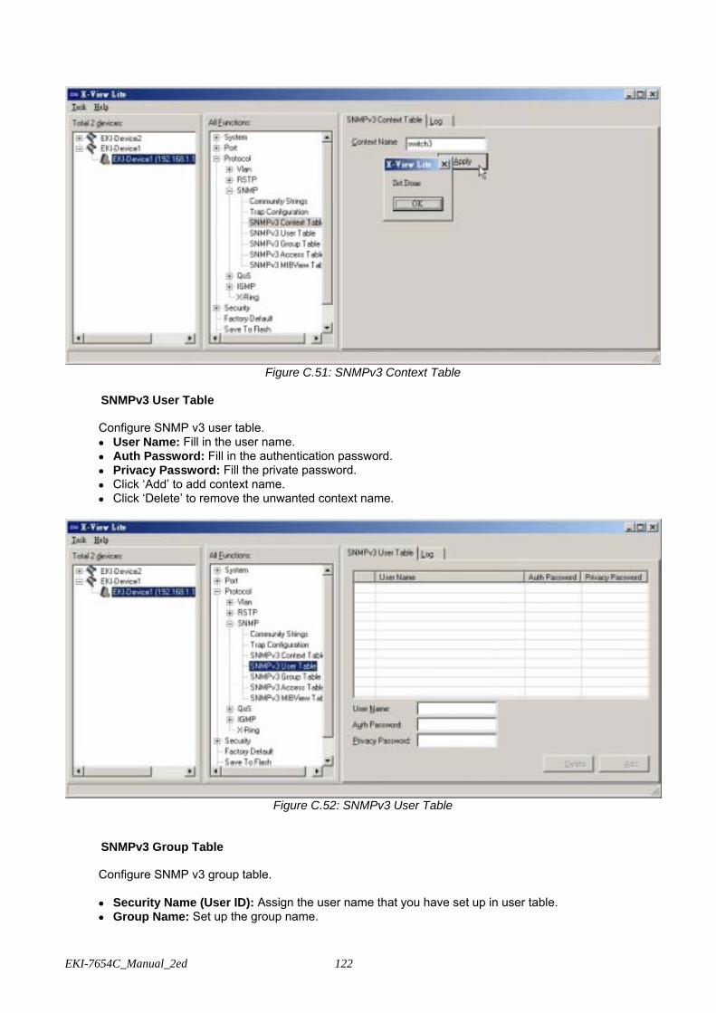
EKI-7654C_Manual_2ed 122
Figure C.51: SNMPv3 Context Table
SNMPv3 User Table
Configure SNMP v3 user table. • User Name: Fill in the user name. • Auth Password: Fill in the authentication password. • Privacy Password: Fill the private password. • Click ‘Add’ to add context name. • Click ‘Delete’ to remove the unwanted context name.
Figure C.52: SNMPv3 User Table
SNMPv3 Group Table Configure SNMP v3 group table. • Security Name (User ID): Assign the user name that you have set up in user table. • Group Name: Set up the group name.

123
• Click ‘Add’ to add context name. • Click ‘Delete’ to remove unwanted context name.
Figure C.53: SNMPv3 Group Table
SNMPv3 Access Table Configure SNMP v3 access table.
Figure C.54: SNMPv3 Access Table
• Context Prefix: Set up the context name. • Group Name: Set up the group. • Security Level: Set up the access level. • Context Match Rule: Select the context match rule. • Read View Name: Set up the read view. • Write View Name: Set up the write view.
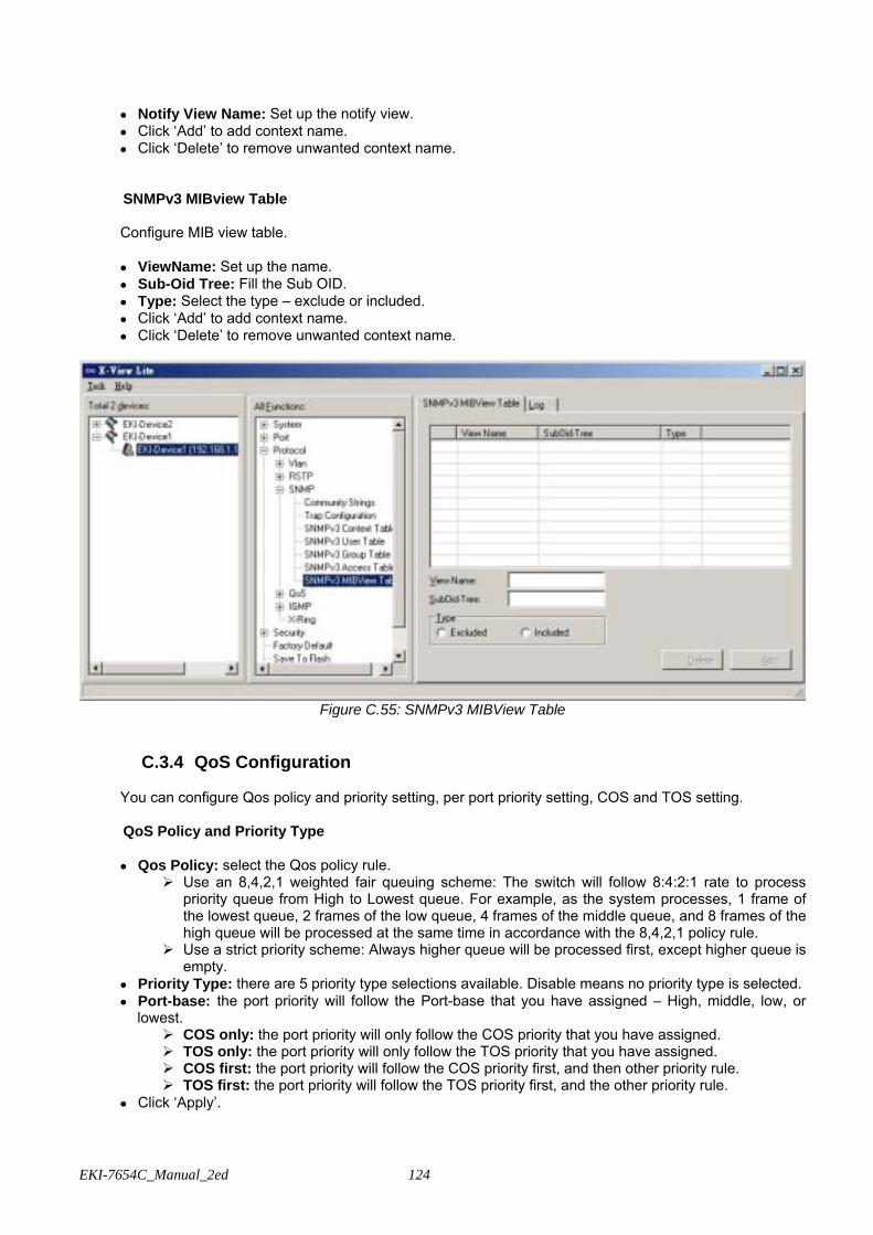
EKI-7654C_Manual_2ed 124
• Notify View Name: Set up the notify view. • Click ‘Add’ to add context name. • Click ‘Delete’ to remove unwanted context name.
SNMPv3 MIBview Table Configure MIB view table. • ViewName: Set up the name. • Sub-Oid Tree: Fill the Sub OID. • Type: Select the type – exclude or included. • Click ‘Add’ to add context name. • Click ‘Delete’ to remove unwanted context name.
Figure C.55: SNMPv3 MIBView Table
C.3.4 QoS Configuration
You can configure Qos policy and priority setting, per port priority setting, COS and TOS setting.
QoS Policy and Priority Type • Qos Policy: select the Qos policy rule.
Use an 8,4,2,1 weighted fair queuing scheme: The switch will follow 8:4:2:1 rate to process priority queue from High to Lowest queue. For example, as the system processes, 1 frame of the lowest queue, 2 frames of the low queue, 4 frames of the middle queue, and 8 frames of the high queue will be processed at the same time in accordance with the 8,4,2,1 policy rule.
Use a strict priority scheme: Always higher queue will be processed first, except higher queue is empty.
• Priority Type: there are 5 priority type selections available. Disable means no priority type is selected. • Port-base: the port priority will follow the Port-base that you have assigned – High, middle, low, or
lowest. COS only: the port priority will only follow the COS priority that you have assigned. TOS only: the port priority will only follow the TOS priority that you have assigned. COS first: the port priority will follow the COS priority first, and then other priority rule. TOS first: the port priority will follow the TOS priority first, and the other priority rule.
• Click ‘Apply’.
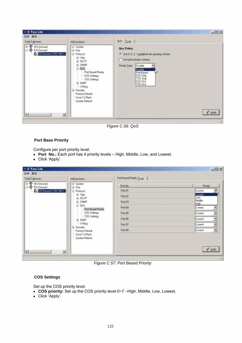
125
Figure C.56: QoS
Port Base Priority Configure per port priority level. • Port No.: Each port has 4 priority levels – High, Middle, Low, and Lowest. • Click ‘Apply’.
Figure C.57: Port Based Priority
COS Settings Set up the COS priority level. • COS priority: Set up the COS priority level 0~7 –High, Middle, Low, Lowest. • Click ‘Apply’.
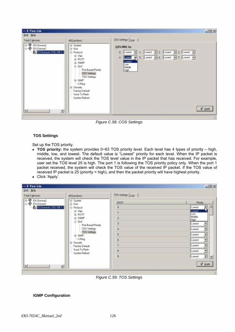
EKI-7654C_Manual_2ed 126
Figure C.58: COS Settings
TOS Settings Set up the TOS priority. • TOS priority: the system provides 0~63 TOS priority level. Each level has 4 types of priority – high,
middle, low, and lowest. The default value is “Lowest” priority for each level. When the IP packet is received, the system will check the TOS level value in the IP packet that has received. For example, user set the TOS level 25 is high. The port 1 is following the TOS priority policy only. When the port 1 packet received, the system will check the TOS value of the received IP packet. If the TOS value of received IP packet is 25 (priority = high), and then the packet priority will have highest priority.
• Click ‘Apply’.
Figure C.59: TOS Settings
IGMP Configuration
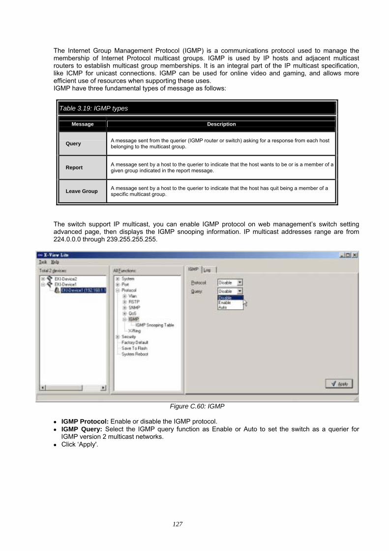
127
The Internet Group Management Protocol (IGMP) is a communications protocol used to manage the membership of Internet Protocol multicast groups. IGMP is used by IP hosts and adjacent multicast routers to establish multicast group memberships. It is an integral part of the IP multicast specification, like ICMP for unicast connections. IGMP can be used for online video and gaming, and allows more efficient use of resources when supporting these uses. IGMP have three fundamental types of message as follows:
Table 3.19: IGMP types
Message Description
Query A message sent from the querier (IGMP router or switch) asking for a response from each host belonging to the multicast group.
Report A message sent by a host to the querier to indicate that the host wants to be or is a member of a given group indicated in the report message.
Leave Group A message sent by a host to the querier to indicate that the host has quit being a member of a specific multicast group.
The switch support IP multicast, you can enable IGMP protocol on web management’s switch setting advanced page, then displays the IGMP snooping information. IP multicast addresses range are from 224.0.0.0 through 239.255.255.255.
Figure C.60: IGMP
• IGMP Protocol: Enable or disable the IGMP protocol. • IGMP Query: Select the IGMP query function as Enable or Auto to set the switch as a querier for
IGMP version 2 multicast networks. • Click ‘Apply'.
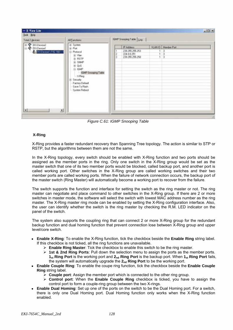
EKI-7654C_Manual_2ed 128
Figure C.61: IGMP Snooping Table
X-Ring X-Ring provides a faster redundant recovery than Spanning Tree topology. The action is similar to STP or RSTP, but the algorithms between them are not the same. In the X-Ring topology, every switch should be enabled with X-Ring function and two ports should be assigned as the member ports in the ring. Only one switch in the X-Ring group would be set as the master switch that one of its two member ports would be blocked, called backup port, and another port is called working port. Other switches in the X-Ring group are called working switches and their two member ports are called working ports. When the failure of network connection occurs, the backup port of the master switch (Ring Master) will automatically become a working port to recover from the failure. The switch supports the function and interface for setting the switch as the ring master or not. The ring master can negotiate and place command to other switches in the X-Ring group. If there are 2 or more switches in master mode, the software will select the switch with lowest MAC address number as the ring master. The X-Ring master ring mode can be enabled by setting the X-Ring configuration interface. Also, the user can identify whether the switch is the ring master by checking the R.M. LED indicator on the panel of the switch. The system also supports the coupling ring that can connect 2 or more X-Ring group for the redundant backup function and dual homing function that prevent connection lose between X-Ring group and upper level/core switch.
• Enable X-Ring: To enable the X-Ring function, tick the checkbox beside the Enable Ring string label.
If this checkbox is not ticked, all the ring functions are unavailable. Enable Ring Master: Tick the checkbox to enable this switch to be the ring master. 1st & 2nd Ring Ports: Pull down the selection menu to assign the ports as the member ports.
1st Ring Port is the working port and 2nd Ring Port is the backup port. When 1st Ring Port fails, the system will automatically upgrade the 2nd Ring Port to be the working port.
• Enable Couple Ring: To enable the coupe ring function, tick the checkbox beside the Enable Couple Ring string label.
Couple port: Assign the member port which is connected to the other ring group. Control port: When the Enable Couple Ring checkbox is ticked, you have to assign the
control port to form a couple-ring group between the two X-rings. • Enable Dual Homing: Set up one of the ports on the switch to be the Dual Homing port. For a switch,
there is only one Dual Homing port. Dual Homing function only works when the X-Ring function enabled.
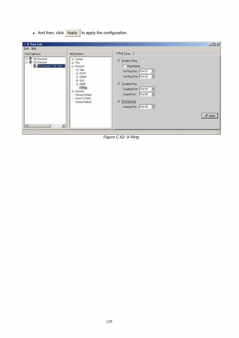
129
• And then, click Apply to apply the configuration.
Figure C.62: X-Ring
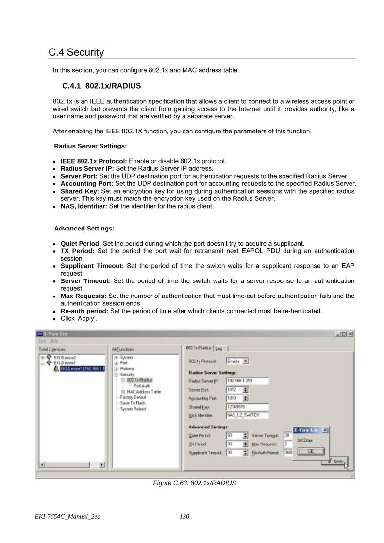
EKI-7654C_Manual_2ed 130
C.4 Security
In this section, you can configure 802.1x and MAC address table.
C.4.1 802.1x/RADIUS 802.1x is an IEEE authentication specification that allows a client to connect to a wireless access point or wired switch but prevents the client from gaining access to the Internet until it provides authority, like a user name and password that are verified by a separate server.
After enabling the IEEE 802.1X function, you can configure the parameters of this function. Radius Server Settings: • IEEE 802.1x Protocol: Enable or disable 802.1x protocol. • Radius Server IP: Set the Radius Server IP address. • Server Port: Set the UDP destination port for authentication requests to the specified Radius Server. • Accounting Port: Set the UDP destination port for accounting requests to the specified Radius Server. • Shared Key: Set an encryption key for using during authentication sessions with the specified radius
server. This key must match the encryption key used on the Radius Server. • NAS, Identifier: Set the identifier for the radius client.
Advanced Settings:
• Quiet Period: Set the period during which the port doesn’t try to acquire a supplicant. • TX Period: Set the period the port wait for retransmit next EAPOL PDU during an authentication
session. • Supplicant Timeout: Set the period of time the switch waits for a supplicant response to an EAP
request. • Server Timeout: Set the period of time the switch waits for a server response to an authentication
request. • Max Requests: Set the number of authentication that must time-out before authentication fails and the
authentication session ends. • Re-auth period: Set the period of time after which clients connected must be re-henticated. • Click ‘Apply’.
Figure C.63: 802.1x/RADIUS
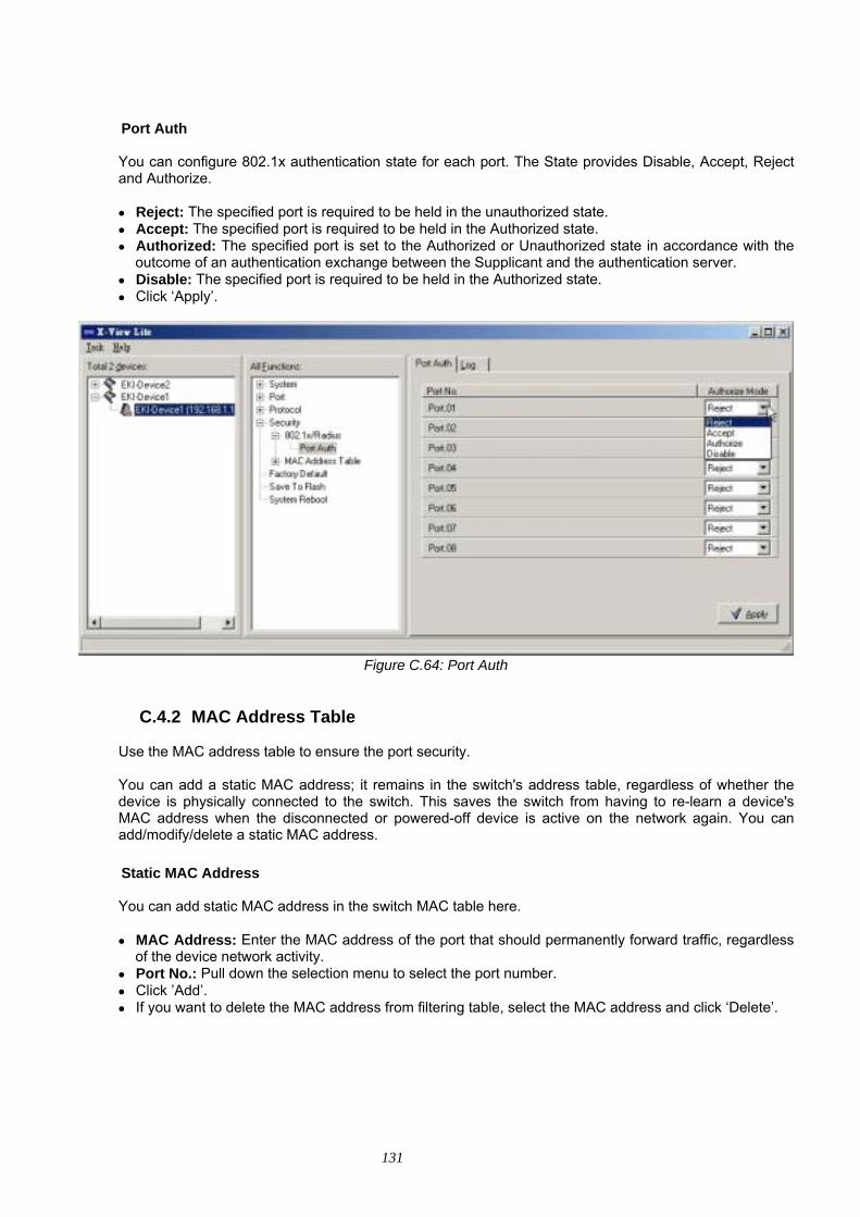
131
Port Auth
You can configure 802.1x authentication state for each port. The State provides Disable, Accept, Reject and Authorize. • Reject: The specified port is required to be held in the unauthorized state. • Accept: The specified port is required to be held in the Authorized state. • Authorized: The specified port is set to the Authorized or Unauthorized state in accordance with the
outcome of an authentication exchange between the Supplicant and the authentication server. • Disable: The specified port is required to be held in the Authorized state. • Click ‘Apply’.
Figure C.64: Port Auth
C.4.2 MAC Address Table Use the MAC address table to ensure the port security.
You can add a static MAC address; it remains in the switch's address table, regardless of whether the device is physically connected to the switch. This saves the switch from having to re-learn a device's MAC address when the disconnected or powered-off device is active on the network again. You can add/modify/delete a static MAC address.
Static MAC Address You can add static MAC address in the switch MAC table here. • MAC Address: Enter the MAC address of the port that should permanently forward traffic, regardless
of the device network activity. • Port No.: Pull down the selection menu to select the port number. • Click ’Add’. • If you want to delete the MAC address from filtering table, select the MAC address and click ‘Delete’.
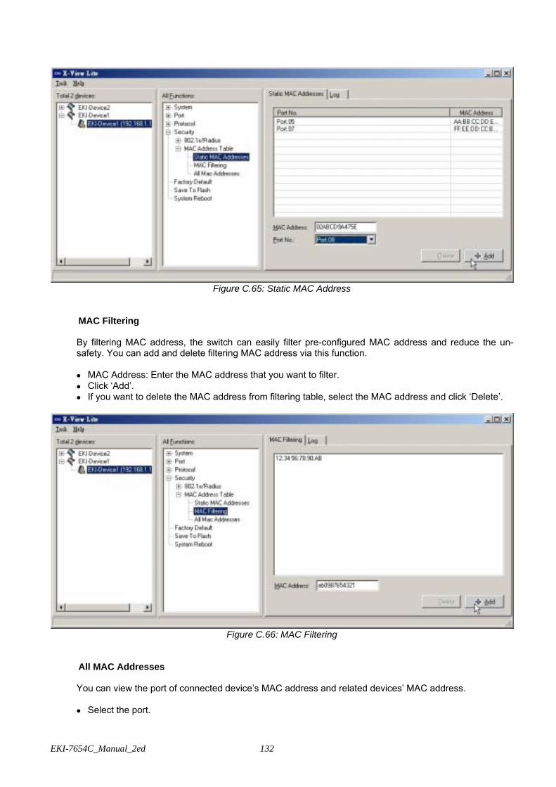
EKI-7654C_Manual_2ed 132
Figure C.65: Static MAC Address
MAC Filtering By filtering MAC address, the switch can easily filter pre-configured MAC address and reduce the un-safety. You can add and delete filtering MAC address via this function.
• MAC Address: Enter the MAC address that you want to filter. • Click ‘Add’. • If you want to delete the MAC address from filtering table, select the MAC address and click ‘Delete’.
Figure C.66: MAC Filtering
All MAC Addresses
You can view the port of connected device’s MAC address and related devices’ MAC address. • Select the port.
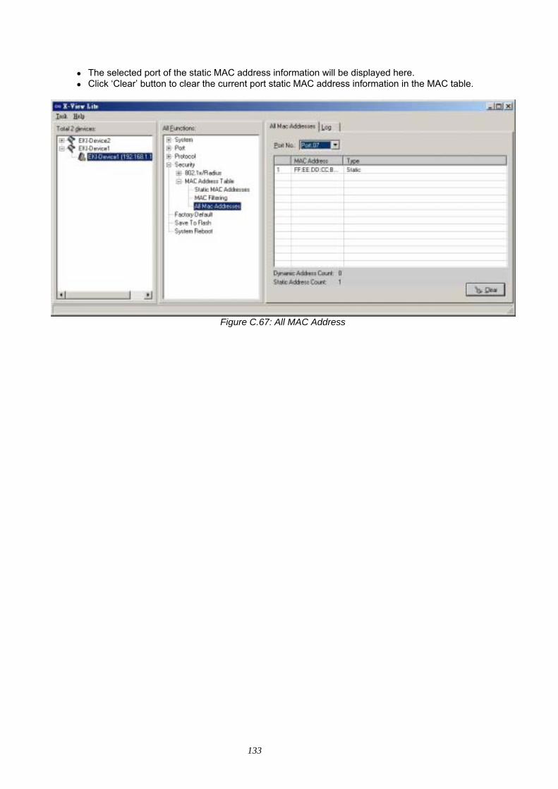
133
• The selected port of the static MAC address information will be displayed here. • Click ‘Clear’ button to clear the current port static MAC address information in the MAC table.
Figure C.67: All MAC Address
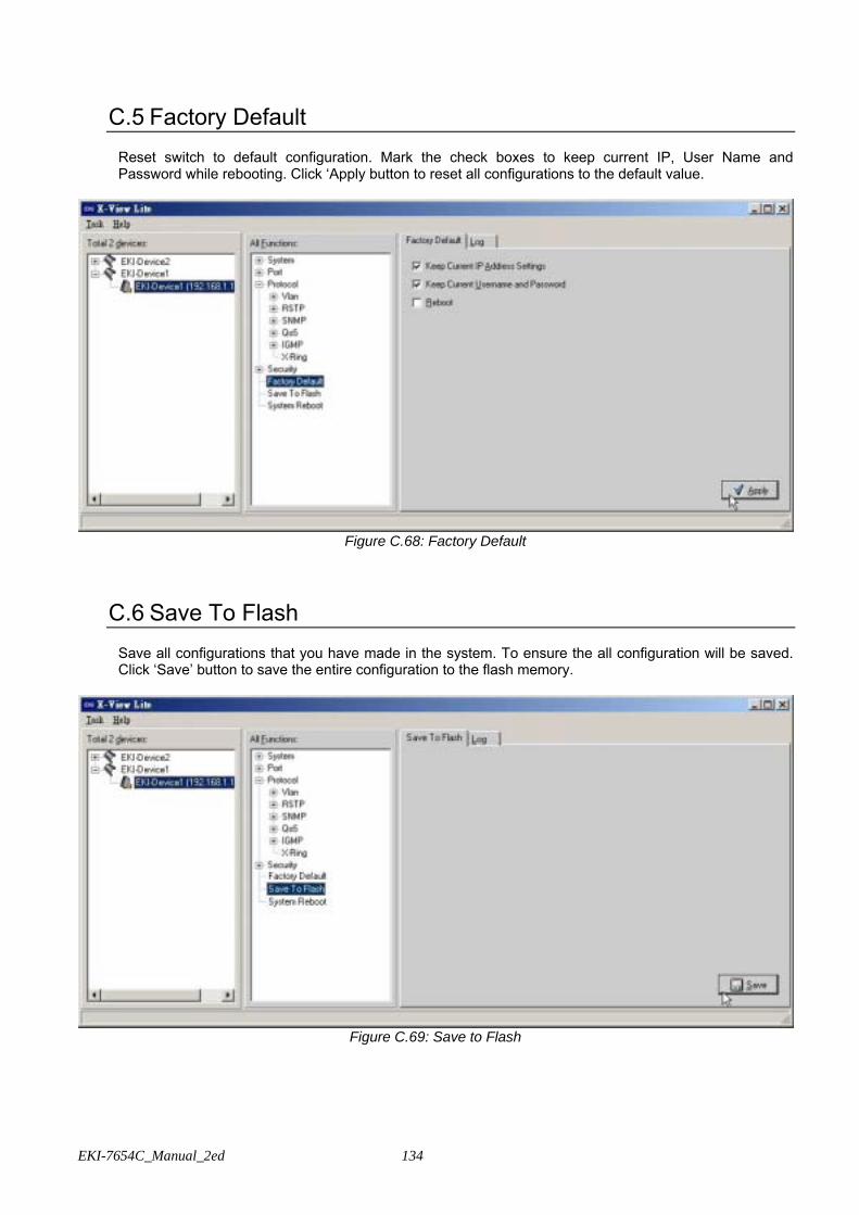
EKI-7654C_Manual_2ed 134
C.5 Factory Default
Reset switch to default configuration. Mark the check boxes to keep current IP, User Name and Password while rebooting. Click ‘Apply button to reset all configurations to the default value.
Figure C.68: Factory Default
C.6 Save To Flash
Save all configurations that you have made in the system. To ensure the all configuration will be saved. Click ‘Save’ button to save the entire configuration to the flash memory.
Figure C.69: Save to Flash
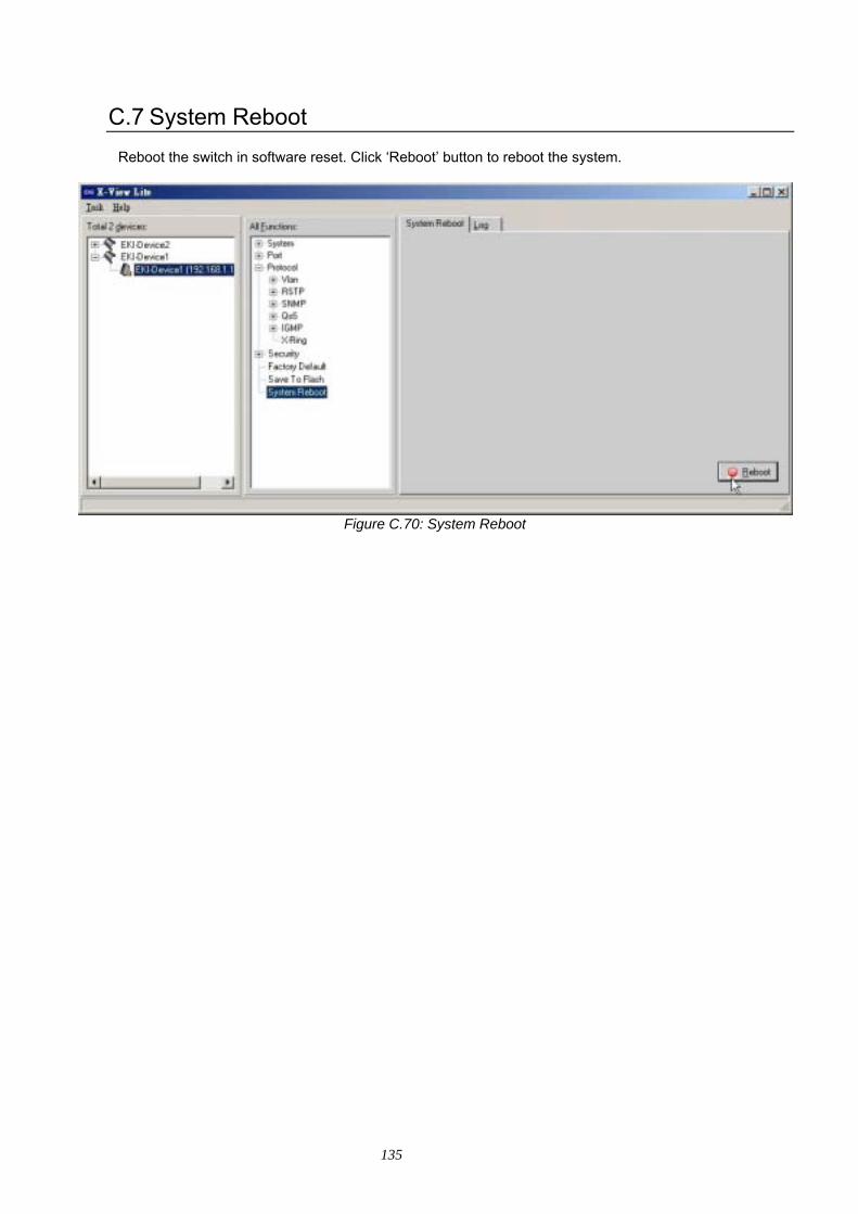
135
C.7 System Reboot
Reboot the switch in software reset. Click ‘Reboot’ button to reboot the system.
Figure C.70: System Reboot