Embed Size (px)
Citation preview

Elastic and inelastic parameters for representing the seismic in-plane behaviour of adobe walls
Nicola Tarque Ruíz
Division of Civil Engineering, Pontificia Universidad Católica del Perú Av. Universitaria 1801, San Miguel, Lima 32, Peru Tel.: +51-1-6262000 IP 4610; Fax: +51-1-6262813
E-mail: [email protected]
Guido Camata Università degli Studi ‘G. D’Annunzio’ Chieti-Pescara
Viale Pindaro 42, 65127 Pescara, Italy Tel.: +39-085-4537276; Fax +39-085-4537255
E-mail: [email protected]
Enrico Spacone Università degli Studi ‘G. D’Annunzio’ Chieti-Pescara
Viale Pindaro 42, 65127 Pescara, Italy Tel.: +39-085-4537276; Fax +39-085-4537255
E-mail: [email protected]
Humberto Varum Division of Civil Engineering, University of Aveiro
Campus Universitário de Santiago, 3810-193 Aveiro, Portugal Tel.: +351-234-370049; Fax: +351-234-370094
E-mail: [email protected]
Marcial Blondet Division of Civil Engineering, Pontificia Universidad Católica del Perú
Av. Universitaria 1801, San Miguel, Lima 32, Peru Tel.: +51-1-6262000 IP 4610; Fax: +51-1-6262813
E-mail: [email protected] Theme 6: Research in Materials and Technology for Conservation and Contemporary Architecture. Keywords: adobe, material, properties, numerical modelling, continuum models. Abstract Nowadays the numerical modelling is becoming an alternative approach for studying the seismic behaviour of structural systems like adobe masonry. Even, it is possible to make parametric studies for understanding the behaviour of different geometrical configuration of adobe houses or the influence on the variation of the material properties. The adobe material is characterized as a brittle material; it has acceptable compression strength but it has poor performance under tensile and shear loading conditions. Until now, there is few research work developed in the field of modelling of adobe structures. In 2005, pseudo static cyclic tests were carried out at the Catholic University of Peru (PUCP) on an unreinforced adobe wall. The objective of this research was to understand the in-plane behaviour of walls under in-plane seismic actions and to test the efficiency of strengthening solutions. Taking benefit of the test results for the unreinforced wall and using non-linear analysis programs, the authors have developed numerical models to represent the in-plane behaviour of adobe walls considering continuum models. The adopted material properties in the models (e.g. elasticity modulus, fracture energy in compression and tension, softening) were defined based on the experimental results. The results of this work allowed establishing a benchmark for the numerical analysis of adobe walls under in-plane seismic actions. The proposed material parameters for numerical modelling allowed predicting well the in-plane seismic capacity and the evolution of damage for adobe walls. Therefore,

this proposed input data could be used for analyzing different configuration of unreinforced adobe walls and constructions. 1. INTRODUCTION Adobe walls, as other type of masonry walls, have a very low tensile strength, thus cracks typically initiate in zones subjected to higher tensile stresses, such as corners of doors and windows. Usually, vertical cracks start at the connection of perpendicular walls, allowing the separation of them, due to the lack of confinement elements. Furthermore, horizontal cracks may form close to the façade base allowing it to overturn due to out-of-plane forces. The typical crack pattern due to in-plane shear forces is X-diagonal shaped, as shown in Figure 1. According to Webster (2008), these cracks are not particularly serious unless the relative displacement across them becomes large, thus initiating the out-of-plane overturning of the small wall blocks formed by the cracks. Horizontal cracks, especially close to the wall base, may also be triggered by in-plane loading. The latter cracks are related to sliding failure modes. Generally, masonry is a composite material formed by bricks and mortar joints. Each masonry component has its own material properties. Mortar is typically weaker and softer than the bricks. However, masonry failure may also involve crushing and tensile fracturing of the masonry bricks and fracturing of the masonry joints (Stavridis & Shing 2010). In the case of adobe structures, the brick and mortar joints are made of similar materials, mainly soil. Therefore, as a first approximation, it seems reasonable to treat the adobe masonry as a homogeneous material. For this reason, the cracking pattern in adobe walls may not distinguish completely between blocks and mortars (Figure 1 right).
Figure 1. Typical in-plane damage in adobe walls.
The state-of-the-art for the numerical modelling of unreinforced masonry, especially for fired clay bricks, point to two main approaches: discrete modelling and smeared crack modelling (Lourenço 1994). In both approaches, the use of elastic and inelastic parameters is required. For adobe masonry, the lack of information and experimental data concerning some of the material properties, particularly in the inelastic regions, makes numerical modelling more uncertain. Therefore, this work focuses on the calibration of the material properties of an adobe wall in order to numerically reproduce its structural behaviour due to in-plane actions. 2. Experimental tests on adobe walls Blondet et al. (2005) carried out a displacement controlled cyclic test (push-pull) on a typical adobe wall at the Catholic University of Peru. The test intended to analyze the wall cyclic response and the damage pattern evolution due to in-plane forces. The wall had an I-shape configuration (Figure 2a), where the main longitudinal wall (with a central window opening) was 3.06 m long, 1.93 m high and 0.30 m thick. The wall also had two 2.48 m long transverse walls that were intended to: a) simulate the influence of the connection with the transversal walls found in typical buildings; b) avoid rocking due to in-plane actions. The specimen was built over a reinforced concrete continuous foundation beam. A reinforced
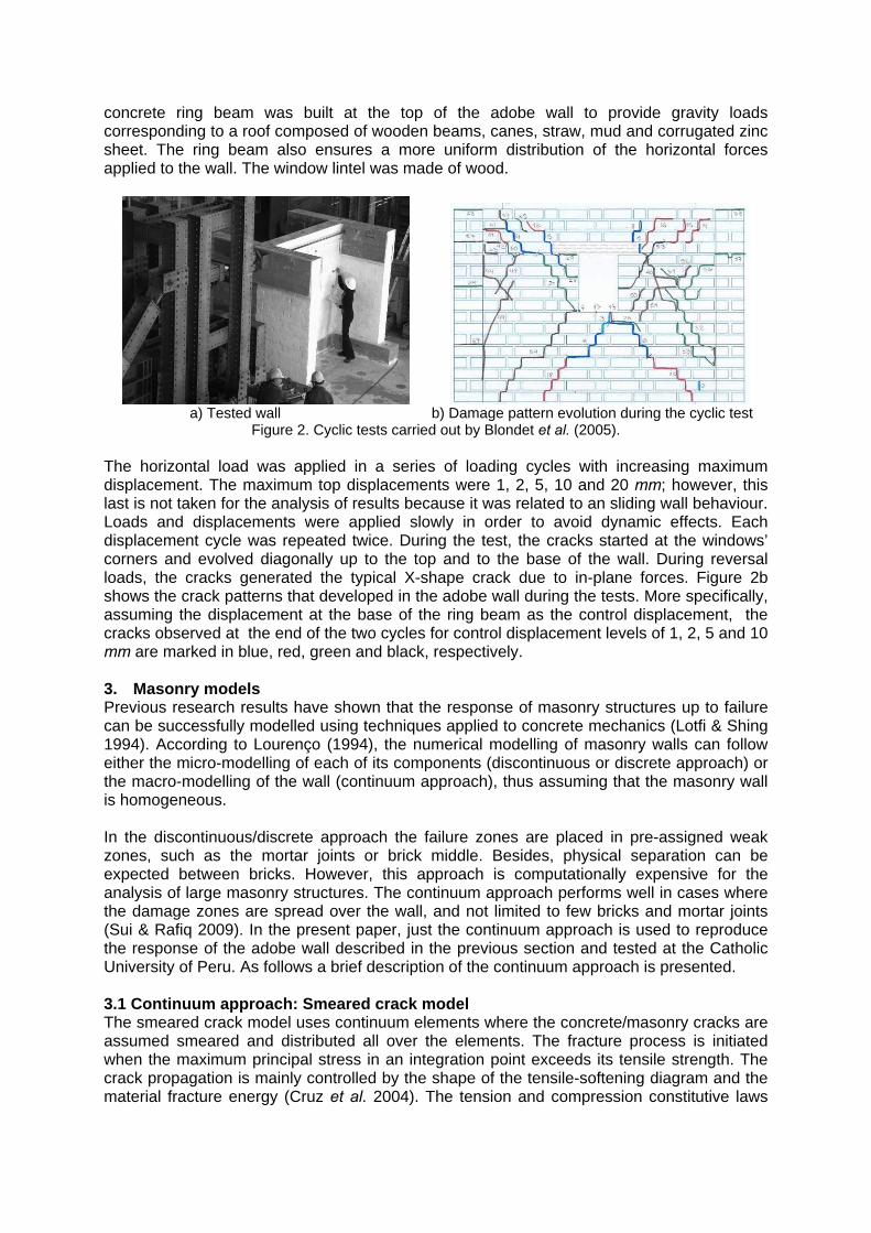
concrete ring beam was built at the top of the adobe wall to provide gravity loads corresponding to a roof composed of wooden beams, canes, straw, mud and corrugated zinc sheet. The ring beam also ensures a more uniform distribution of the horizontal forces applied to the wall. The window lintel was made of wood.
a) Tested wall b) Damage pattern evolution during the cyclic test
Figure 2. Cyclic tests carried out by Blondet et al. (2005). The horizontal load was applied in a series of loading cycles with increasing maximum displacement. The maximum top displacements were 1, 2, 5, 10 and 20 mm; however, this last is not taken for the analysis of results because it was related to an sliding wall behaviour. Loads and displacements were applied slowly in order to avoid dynamic effects. Each displacement cycle was repeated twice. During the test, the cracks started at the windows’ corners and evolved diagonally up to the top and to the base of the wall. During reversal loads, the cracks generated the typical X-shape crack due to in-plane forces. Figure 2b shows the crack patterns that developed in the adobe wall during the tests. More specifically, assuming the displacement at the base of the ring beam as the control displacement, the cracks observed at the end of the two cycles for control displacement levels of 1, 2, 5 and 10 mm are marked in blue, red, green and black, respectively. 3. Masonry models Previous research results have shown that the response of masonry structures up to failure can be successfully modelled using techniques applied to concrete mechanics (Lotfi & Shing 1994). According to Lourenço (1994), the numerical modelling of masonry walls can follow either the micro-modelling of each of its components (discontinuous or discrete approach) or the macro-modelling of the wall (continuum approach), thus assuming that the masonry wall is homogeneous. In the discontinuous/discrete approach the failure zones are placed in pre-assigned weak zones, such as the mortar joints or brick middle. Besides, physical separation can be expected between bricks. However, this approach is computationally expensive for the analysis of large masonry structures. The continuum approach performs well in cases where the damage zones are spread over the wall, and not limited to few bricks and mortar joints (Sui & Rafiq 2009). In the present paper, just the continuum approach is used to reproduce the response of the adobe wall described in the previous section and tested at the Catholic University of Peru. As follows a brief description of the continuum approach is presented. 3.1 Continuum approach: Smeared crack model The smeared crack model uses continuum elements where the concrete/masonry cracks are assumed smeared and distributed all over the elements. The fracture process is initiated when the maximum principal stress in an integration point exceeds its tensile strength. The crack propagation is mainly controlled by the shape of the tensile-softening diagram and the material fracture energy (Cruz et al. 2004). The tension and compression constitutive laws
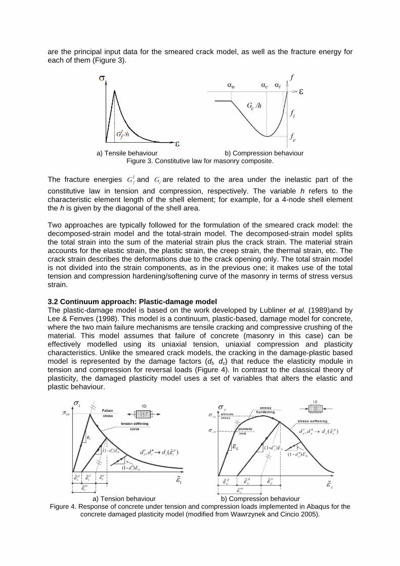
are the principal input data for the smeared crack model, as well as the fracture energy for each of them (Figure 3).
a) Tensile behaviour b) Compression behaviour
Figure 3. Constitutive law for masonry composite.
The fracture energies IfG and cG are related to the area under the inelastic part of the
constitutive law in tension and compression, respectively. The variable h refers to the characteristic element length of the shell element; for example, for a 4-node shell element the h is given by the diagonal of the shell area. Two approaches are typically followed for the formulation of the smeared crack model: the decomposed-strain model and the total-strain model. The decomposed-strain model splits the total strain into the sum of the material strain plus the crack strain. The material strain accounts for the elastic strain, the plastic strain, the creep strain, the thermal strain, etc. The crack strain describes the deformations due to the crack opening only. The total strain model is not divided into the strain components, as in the previous one; it makes use of the total tension and compression hardening/softening curve of the masonry in terms of stress versus strain. 3.2 Continuum approach: Plastic-damage model The plastic-damage model is based on the work developed by Lubliner et al. (1989)and by Lee & Fenves (1998). This model is a continuum, plastic-based, damage model for concrete, where the two main failure mechanisms are tensile cracking and compressive crushing of the material. This model assumes that failure of concrete (masonry in this case) can be effectively modelled using its uniaxial tension, uniaxial compression and plasticity characteristics. Unlike the smeared crack models, the cracking in the damage-plastic based model is represented by the damage factors (dt, dc) that reduce the elasticity module in tension and compression for reversal loads (Figure 4). In contrast to the classical theory of plasticity, the damaged plasticity model uses a set of variables that alters the elastic and plastic behaviour.
a) Tension behaviour b) Compression behaviour Figure 4. Response of concrete under tension and compression loads implemented in Abaqus for the
concrete damaged plasticity model (modified from Wawrzynek and Cincio 2005).

4. FINITE ELEMENT MODELS, MONOTONIC LOADING The adobe wall tested by Blondet et al. (2005), Figure 2a, is modelled based on the total-strain model and the concrete damaged plasticity model for representation of a monotonic displacement. Figure 5a shows the regular distribution of quadrilateral shell elements. The first model is analyzed with Midas FEA v2.9.6 (2009) while the second one with Abaqus 6.9 SIMULIA (2009). All models include the top and base reinforced concrete beams, the adobe walls and the timber lintel. The base is fully fixed, as seen in Figure 5b. Since the experimental test was displacement-controlled, a monotonic top displacement was applied to the numerical model at one vertical edge of the top concrete beam up to a maximum displacement of 10 mm (Figure 5b). At higher displacement levels, wall instability started during the experimental test and though the test was not interrupted, the results beyond 10 mm were not considered reliable.
a) Shell elements b) Constraints and top load
Figure 5. Numerical model of the tested adobe wall. In Midas FEA, the lateral displacement is imposed incrementally following the arc-length iterative procedure in combination with the initial stiffness. The convergence criterion is controlled through a displacement and an energy norm ratio, 0.005 and 0.01, respectively. In Abaqus/Standard, the top-displacement is imposed following a full Newton-Raphson iterative procedure. An automatic stabilization is selected for the convergence criterion, with a specified dissipated energy fraction of 0.001 and an adaptive stabilization with maximum ratio of stabilization to strain energy of 0.01. In both software the nonlinear geometric effects are considered. As previously mentioned, a complete database of material properties for adobe bricks and walls used in Peru is not available. The scarce available data refers to compression strength and elastic properties only (e.g. module of elasticity). The lack of data for defining the inelastic properties of adobe, such as the fracture energy in compression and tension, introduces large uncertainties in the analyses. The values for the inelastic parameters used in the present study were derived through a correlation study between experimental and numerical results and calibrated with parametric studies; further details can be seen in Tarque (2011). 4.1 Continuum approach: Total-strain model The model is built with first order rectangular 4 nodes-shell elements. The size of each element is about 100 x 100 mm. The characteristic element length h in Midas FEA is given by (2A)0.5, where A is the area of the element. The concrete beams and the lintel are represented by elastic and isotropic materials. The adobe masonry, which is defined here as an isotropic material, makes use of the tension and compression constitutive laws for representing the inelasticity of the material within the total-strain approach (Figure 6). An exponential function is defined for the tension behaviour and a parabolic one (similar to the

function given by Lourenço 1996) is given for the compression response. Since experimental data for the softening behaviour in tension and compression is not available, the inelastic strain values are assumed based on the ones for clay masonry and calibrated to match the experimental pushover curve. The obtained values are shown in Table 1, where εp is the plastic strain related to the maximum compression strength.
0
0.005
0.01
0.015
0.02
0.025
0.03
0.035
0.04
0.045
0 0.0025 0.005 0.0075 0.01
Strain (mm/mm)
Str
ess
(MP
a)
0
0.05
0.1
0.15
0.2
0.25
0.3
0.35
0 0.0025 0.005 0.0075 0.01 0.0125
Strain (mm/mm)
Str
ess
(M
Pa)
a) Tension b) Compression
Figure 6. Constitutive laws for the material model in Midas FEA.
Table 1. Adobe masonry material properties used for the continuum approach, monotonic representation.
Elastic Tension Compression E
(MPa) υ γm
(N/mm3) h
(mm) ft
(N/mm2)Gft
(N/mm) fc
(N/mm2)Gfc
(N/mm) εp
(mm/mm) 200 0.2 2e-05 141 0.04 0.01 0.30 0.103 0.002
The elastic module E was selected from available adobe masonry tests (as reported in Tarque 2011) and then calibrated to match the initial stiffness of the pushover envelope curve obtained from the test. A compression strength fc close to 0.70 MPa is specified in the literature (test on adobe piles), but the complete definition of the uniaxial behaviour law is not available. The authors believe that tests on adobe piles don’t represent the actual adobe behaviour because they consider a portion not representative of the wall. In addition they tend to underestimate the compressive strength of the adobe masonry and that larger specimens should be used. Tensile strength and fracture energy are calibrated in this model using the experimental test results, since no data were found in the literature. Since a fixed crack model is selected, a reduction of the shear stiffness β= 0.05 was selected. The elastic material properties for the concrete and timber are the presented in Table 2.
Table 2. Elastic material properties for concrete and timber. Concrete Timber
E (MPa) υ γm (N/mm3) E (MPa) υ γm (N/mm3) 22000 0.25 2.4e-05 10000 0.15 6.87e-06
Figure 7a shows the wall displacements and Figure 7b shows the crack pattern of the model (e.g. closed, partially open, fully open, etc.) at the analysis end. The strain pattern is in good agreement with the failure pattern observed in the test (Figure 2b). The target maximum displacement was 10 mm. As in the previous model, cracks start at the openings corners and progresses diagonally to the wall edges. Figure 7b shows that the maximum strains are reached at the contact zone of the wall with the timber lintel and at the corner openings; this is due to high stress concentration at those zones.

a) Displacement (mm) b) Crack status
Figure 7. Displacement and crack status corresponding to the numerical model (P: partially open; O: fully open; C: closed), Midas FEA.
4.2 Continuum approach: Concrete damaged plasticity model Abaqus 6.9 SIMULIA (2009) does not have a specific constitutive model for masonry structures, but models implemented for concrete and other quasi-brittle materials are commonly used to model masonry. The concrete damaged plasticity model, which accounts for both tensile cracking and compressive crushing, can be effectively applied to masonry too. This model decomposes the total strain into an elastic and a plastic part, and the effect of material cracking (especially for unloading) is represented with damage factors. As in the previous case, this model is built with rectangular 4 nodes-shell elements. The size of each element is about 100 x 100 mm. Similar to the total strain model, in the concrete damaged plasticity model the inelasticity of the material is represented separately in tension and compression. In Abaqus/Standard, the material properties are defined by the stress versus plastic strains constitutive laws. The material properties used in this model are the same as those specified in Table 1 for Midas FEA; however, and as it is explained later, the compression strength can be increased until 0.70 MPa and still obtaining good results. Figure 8a shows the wall displacement at the last step of the displacement loading. Figure 8b shows the damage pattern due to tension stresses. The diagonal cracks control the wall behaviour and extend from the opening corners to the wall corners. The red arrows show the tensile plastic strains and the yellow arrows indicate the compression plastic strains. The largest strains are observed at contact between the timber lintel and the wall and at the opening corners. The horizontal crack pattern at the transversal walls is in agreement with the real failure pattern.
a) Displacement (mm) b) Tensile plastic strain
Figure 8. Displacement and tensile plastic strain of the adobe wall considering the concrete damage plasticity model, Abaqus/Standard.

5. COMPARISON OF THE ANALYTICAL AND EXPERIMENTAL FORCE-DISPLACEMENT CURVES
The two numerical models reproduced fairly well the general response, as shown in Figure 9, the stress distribution and the crack pattern of the experimental test. The material properties showed in previous tables were obtained from a parametric study in order to understand how each individual parameter affects the response (Tarque 2011). The convergence parameters for Midas FEA and Abaqus/Standard were calibrated through a parametric investigation to obtain a reasonable solution of the numerical models.
0
5
10
15
20
25
30
35
40
45
0 2 4 6 8 10
Displacement (mm)
For
ce (
kN)
Envelop, experimental
Midas:total-strain model
Abaqus: concretedamage plasticity model
Figure 9. Force-displacement curves: experimental results and numerical modelling.
When the wall enters in the inelastic range (approximately after 1 mm of top displacement) small differences between numerical and experimental curves are observed due to different initiation of the crack propagation. However, as the crack patterns stabilize, all the curves match well the experimental response (after approximately 2 mm). The first elements that reach the maximum tensile strength are those located at the opening and lintel corners, where stress concentration is expected. Also, horizontal cracks appear at the transversal walls. The force-displacement curves are more sensitive to the variation of tensile strength than to the variation of compressive strength, this is clearer seen in the analysis performed in Abaqus/Standar. To compare the effect of strength variability, an additional analysis considering values of fc from 0.30 to 0.80 MPa, with a fracture energy proportional to the one
considered for fc= 0.30 MPa (i.e. cfG /fc= 0.344), is performed in Abaqus/Standard and the
results are shown in Figure 10. Here it is preliminary concluded that the compression strength does not have much influence on the global response of the adobe masonry, it just increment a little the maximum lateral strength.
0
5
10
15
20
25
30
35
40
45
0 2 4 6 8 10
Displacement (mm)
Fo
rce
(k
N)
ExperimentalAbaqus, fc= 0.30 MPaAbaqus, fc= 0.45 MPaAbaqus, fc= 0.70 MPaAbaqus, fc= 0.80 MPa
Figure 10. Sensitivity of force-displacement curves to variation of fc with fixed ft= 0.04 MPa.

6. CONCLUSIONS This paper focuses on the calibration of the material properties of the adobe masonry in order to calculate its in-plane seismic capacity. An experimental cyclic test carried out on an adobe wall is reproduced here through a finite element model. Two numerical models were created considering the total-strain and the concrete damage plasticity models. All models were able to reproduce fairly close the in-plane behaviour of the adobe wall tested, including crack initiation and crack propagation. Using the smeared approach, a parametric study was performed in order to investigate the influence of the compressive and tensile strength on the wall response. The results showed that the influence of the compressive strength on the global behaviour of the adobe wall is minor, while the tensile strength plays an important role and controls the global behaviour, during loading and unloading, especially the post peak behaviour. When the maximum tensile strength is reached in one element, stress redistribution occurs and the wall response becomes nonlinear. The lack of experimental data for the evaluation of the hardening/softening behaviour of the adobe material makes difficult to predict numerically the adobe wall response; although, the calibrated material properties represent well the experimental force-displacement curve. Especially for analysis in Abaqus/Standard and considering a continuum approach, the
compression strength for adobe masonry can be taken as 0.45 MPa with a ratio cfG /fc= 0.344
mm, and the tensile strength ft as 0.04 MPa with IfG = 0.01 N/mm, related to a characteristic
element length h= 141.1 mm. REFERENCES
Abaqus 6.9 SIMULIA, 2009. Abaqus/CAE Extended Funcionality EF2. Manual. Providence, RI, USA: Dassault Systemss Corporation.
Blondet, M. et al., 2005. Using industrial materials for the construction of safe adobe houses in seismic areas. In Proceedings of Earth Build 2005 Conference. Sydney, Australia.
Cruz, J.S., Barros, J. & Azevedo, Á., 2004. Elasto-plastic multi-fixed smeared crack model for concrete. Report 04-DEC/E-05. Minho, Portugal: University of Minho.
Lee, J. & Fenves, G.L., 1998. Plastic-Damage Model for Cyclic Loading of Concrete Structures. Journal of Engineering Mechanics, 124(8), pp.892-900. Available at: http://link.aip.org/link/JENMDT/v124/i8/p892/s1&Agg=doi [Accessed May 19, 2011].
Lotfi, H.R. & Shing, P. Benson, 1994. Interface Model Applied to fracture of masonry Structures. ASCE, 120(1), pp.63-80.
Lourenço, P.B., 1994. Analysis of masonry structures with interface elements: Theory and Applications. Report. Delft, The Netherlands: Delft University.
Lourenço, P.B., 1996. Computational strategies for masonry structures. Ph.D. Thesis. Delft, The Netherlands: Delft University.
Lubliner, J. et al., 1989. A plastic-damage model for concrete. International Journal of Solids and Structures, 25(3), pp.299-326. Available at: http://linkinghub.elsevier.com/retrieve/pii/0020768389900504.

Midas FEA v2.9.6, 2009. Nonlinear and detail FE Analysis System for civil structures. Manual: Analysis and Algorithm Midas Info., CSP FEA.
Stavridis, A. & Shing, P . B., 2010. Finite Element Modeling of Nonlinear Behavior of Masonry-Infilled RC Frames. Journal of Structural Engineering, ASCE, 136(3), 285-296., 3(136), pp.285-296.
Sui, C. & Rafiq, M.Y., 2009. Laterally loaded masonry wall panels: a review of numerical models. Journal of the International Masonry Society, 22(2), pp.47-52.
Tarque Ruíz, N., 2011. Numerical modelling of the seismic behaviour of adobe buildings. Ph.D. Thesis. Pavia, Italy: ROSE School, Istituto di Studi Superiori di Pavia IUSS.
Wawrzynek, A. & Cincio, A., 2005. Plastic-damage macro-model for non-linear masonry structures subjected to cyclic or dynamic loads. In Proceedings of Conf. Analytical Models and New Concepts in Concrete and Masonry Structures, AMCM’2005. Gliwice, Poland. Available at: http://kateko.rb.polsl.pl/katedra/sylwetki/publikacje/awaw/AMCM--A50f.pdf.
Webster, F., 2008. Earthen Structures: Assessing Seismic Damage, Performance, and Interventions. In E. Avrami, H. Guillaud, & M. Hardy, eds. Terra Literature Review, An Overview of Research in Earthen Architecture Conservation. Los Angeles, California, USA: http://www.getty.edu/conservation/publications/pdf_publications/terra_lit_review.pdf, pp. 69-79.
Curriculum: Nicola Tarque is a Lecturer at the Catholic University of Peru and PhD candidate at ROSE School – Istituto Universitario di Studi Superiori di Pavia, Italy. His main research topics include masonry constructions and seismic risk assessment. Guido Camata is an Assistant Professor of Structural Engineering at the University of Chieti-Pescara. He worked at ISIS Canada (Intelligent Sensing for Innovative Structures) in Winnipeg, Canada, and after at the University of Colorado at Boulder. His research experience includes both experimental and numerical work. Enrico Spacone, a professor of Structural Engineering, is Chair of the department of Engineering at the University of Chieti-Pescara. His research focuses on modelling and analysis of structures under seismic loads. Humberto Varum, Associate Professor at the Civil Engineering Department, University of Aveiro, Portugal, member of the National Committee of ICOMOS. His main research interests include earth construction characterization and seismic strengthening. Marcial Blondet is Professor of Civil Engineering at the Catholic University of Peru. He obtained Masters and PhD degrees in Engineering at the University of California, Berkeley. Professor Blondet is a specialist in earthquake engineering and structural dynamics, and has ample experience on the experimental study of the seismic behaviour of structures. His main research interests are the use of energy dissipation and base isolation systems for the seismic protection of buildings, the development of low-cost solutions to mitigate the seismic risk of informal earthen and masonry dwellings, and the conservation of earthen historical monuments in seismic areas.