Embed Size (px)
Citation preview

http://www.tytlabs.com/review/© Toyota Central R&D Labs., Inc. 2016
11R&D Review of Toyota CRDL, Vol.47 No.3 (2016) 11-26
1. Introduction
In the initial design of vehicle bodies, the full plastic strength of the frame section is typically evaluated to determine the sectional shape, accounting for static strength, rigidity, and collision performance. Basing the evaluation on the full plastic strength effectively utilizes all the steel plating comprising the cross section, and the strength is determined with all the sheet plates at their yield point.
In modern vehicle bodies, the use of high-strength steel plates is becoming increasingly common in order to reduce weight while maintaining strength, and this is resulting in progressively thinner frame structures. When external forces act upon such thin-walled frames, their rigidity sometimes decreases before plastic deformation occurs. This is mainly because, as the thin plates elastically buckle under compressive stress, areas of the section lose their ability to spread the load. The thinner the plates, the more susceptible they are to elastic buckling. Since buckling also reduces
the maximum load before plastic collapse, evaluations based on the full plastic strength may overestimate the strength. Thus, various evaluation methods have been proposed and are currently in practical use to replace those using the full plastic strength. Effective width theory is one method of analyzing the effects of elastic buckling, and strength evaluations have been proposed based on this theory. Using computer-aided engineering (CAE), an application of the finite element method (FEM), rigidity and strength can be calculated to a high degree of accuracy.
However, building a CAE calculation model in the initial stages of design is difficult since the vehicle shape is often not completely fixed. Also, it is not easy to redesign the basic shape, even if it turns out that it will not meet the design requirements after the detailed shape is fixed. Therefore, it is important to understand elastic buckling phenomenon for thin-walled frames at the initial design stages in order to create an effective design and develop vehicle frames efficiently.
Buckling of thin-walled frames is analyzed based on
Buckling, Thin-walled Box Beam, FEM, Buckling Stress Interaction Formula, Torsion
Recently, high-strength steel is being increasingly used in the plates that constitute the frames of vehicles. Since these plates are becoming thinner, the buckling is an important issue in the automotive industry. A variety of solutions to this problem have been proposed, some of which are currently in practical use. In this paper, an equation is first derived for simply expressing the shear stress on plates subjected to torsional buckling in the box beams that make up the frame. Although a precise equation can be derived using the energy method, this equation is complex and difficult to implement. Therefore, an approximation equation is proposed based on this precise equation and shear buckling stress of plates. The accuracy of the proposed equation is evaluated by comparing it to the results of an analysis using the finite element method (FEM). It is found that the difference in shear stress under torsional buckling is less than about 5% for a cross-sectional aspect ratio of 0.4-1.0. Then, an interaction formula for compressive and shear stresses is derived for thin-walled box beams subjected to a compressive force and torsional torque based on the well-known buckling stress interaction formulas for a plate. The accuracy of the proposed interaction formula is then evaluated by comparing with the results of FEM calculations. It is shown that the well-known equations for the plates can be obtained by approximating the buckling eigen equations derived using the energy method, assuming a deformed shape with low-order terms. In addition, the proposed interaction formula is found to be different depending on the structural parameters used.
Report received on Jul. 4, 2016
Katsuya Furusu, Tatsuyuki Amago and Toshiaki Nakagawa
Elastic Buckling Analysis for Compression and Torsion in Thin-walled Box Beams
Research Report
Special Feature: Dynamics Modeling Supporting Vehicle Performance
http://www.tytlabs.com/review/
12
© Toyota Central R&D Labs., Inc. 2016
R&D Review of Toyota CRDL, Vol.47 No.3 (2016) 11-26
verify the accuracy of the derived equations. Also, since vehicle body frames are being considered, the aspect ratio (short side h / long side b) for the box section is taken to be within the range 0.4-1.0. Similarly, the discussion applies to beams with rectangular plates with aspect ratios (width b or h / length l ) of 1/3 or lower.
2. Well-known Basic Equations for Buckling ofPlate and Box Beam
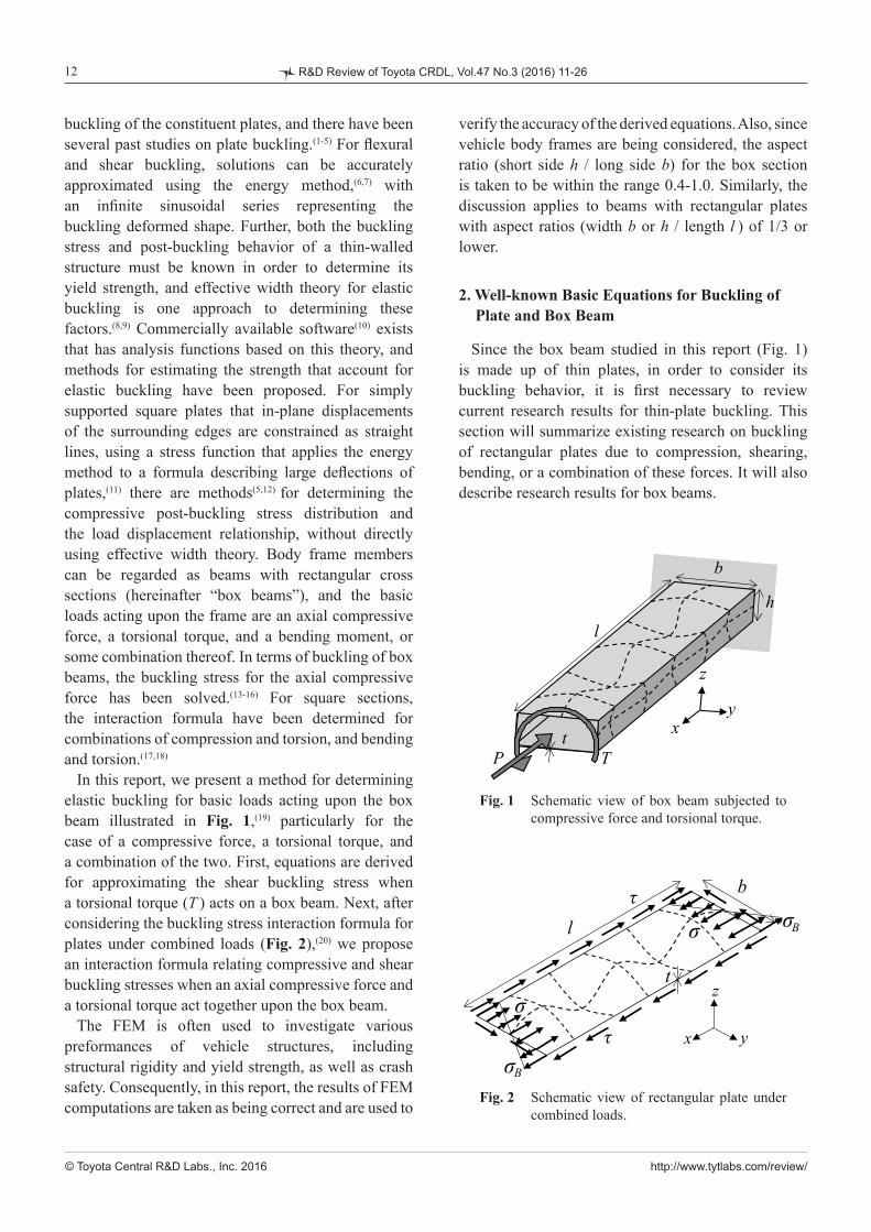
Since the box beam studied in this report (Fig. 1) is made up of thin plates, in order to consider its buckling behavior, it is first necessary to review current research results for thin-plate buckling. This section will summarize existing research on buckling of rectangular plates due to compression, shearing, bending, or a combination of these forces. It will also describe research results for box beams.
buckling of the constituent plates, and there have been several past studies on plate buckling.(1-5) For flexural and shear buckling, solutions can be accurately approximated using the energy method,(6,7) with an infinite sinusoidal series representing the buckling deformed shape. Further, both the buckling stress and post-buckling behavior of a thin-walled structure must be known in order to determine its yield strength, and effective width theory for elastic buckling is one approach to determining these factors.(8,9) Commercially available software(10) exists that has analysis functions based on this theory, and methods for estimating the strength that account for elastic buckling have been proposed. For simply supported square plates that in-plane displacements of the surrounding edges are constrained as straight lines, using a stress function that applies the energy method to a formula describing large deflections of plates,(11) there are methods(5,12) for determining the compressive post-buckling stress distribution and the load displacement relationship, without directly using effective width theory. Body frame members can be regarded as beams with rectangular cross sections (hereinafter “box beams”), and the basic loads acting upon the frame are an axial compressive force, a torsional torque, and a bending moment, or some combination thereof. In terms of buckling of box beams, the buckling stress for the axial compressive force has been solved.(13-16) For square sections, the interaction formula have been determined for combinations of compression and torsion, and bending and torsion.(17,18)
In this report, we present a method for determining elastic buckling for basic loads acting upon the box beam illustrated in Fig. 1,(19) particularly for the case of a compressive force, a torsional torque, and a combination of the two. First, equations are derived for approximating the shear buckling stress when a torsional torque (T ) acts on a box beam. Next, after considering the buckling stress interaction formula for plates under combined loads (Fig. 2),(20) we propose an interaction formula relating compressive and shear buckling stresses when an axial compressive force and a torsional torque act together upon the box beam.
The FEM is often used to investigate various preformances of vehicle structures, including structural rigidity and yield strength, as well as crash safety. Consequently, in this report, the results of FEM computations are taken as being correct and are used to
Fig. 2 Schematic view of rectangular plate under combined loads.
Fig. 1 Schematic view of box beam subjected to compressive force and torsional torque.
x y
z
l
t
b
σ
σ
τ
τσB
σB
Bσστ
τσ
σB

http://www.tytlabs.com/review/
13
© Toyota Central R&D Labs., Inc. 2016
R&D Review of Toyota CRDL, Vol.47 No.3 (2016) 11-26
2. 2 Box Beam Compression and Torsional Buckling
Kuranishi(13-16) investigated axial compression buckling for shearing of a box beam. He determined the buckling stress assuming no deflection in the ridge connecting two plates (maintaining a straight line), a ridge with no simple rotation support for the plates, a certain rigidity, and coupling between the deflection angle and the moment of the adjoining plates. The steps given here can be applied to any sectional shape formed by a combination of thin plates, not just rectangular sections. The buckling stress is expressed as:
, (8)
where kC is the buckling stress coefficient, which is a function of the sectional aspect ratio (h/b). As illustrated in Fig. 3,(20) this equation does have an explicit form.
Wittrick and Curzon(17,18) determined a buckling and buckling stress interaction formula for beams of infinitely long equilateral triangular and square sections under compression and torsion. It should be noted that the buckling deformation mode will vary greatly with load ratio and illustrates the relationship with buckling stress. Figure 4(20) depicts the buckling stress interaction formula curve in square box beams as determined by Wittrick and Curzon.
2. 1 Buckling of Rectangular Plates and BucklingStress Interaction Formula
We will consider a simply supported rectangular plate with a length l, width b, and thickness t as shown in Fig. 2 (Young’s modulus is E and Poisson’s ratio is µ). As shown in the figure, when a compressive stress σ, shear stress τ, and bending stress σB independently act upon the rectangular plate, the buckling stresses σ̂cr, τ̂cr, and σ̂Bcr are as given by(1,2,4)
, , (1)
, (2)
, , (3)
, . (4)
Note that the buckling stresses for an individual plate are written with a carat (^) to differentiate them from the buckling stresses for the box beam. For buckling under combined loads, the acting stresses are expressed using a buckling stress interaction formula. For compression, shearing, and flexural buckling, with stress components of σ̂ 'cr, τ̂ 'cr, and σ̂'Bcr, respectively, compression and shearing are related as:
, (5)
, (6)
. (7)
Equation (5) represents the buckling stress relationship determined by Iguchi,(21,22) expressed as a regression formula. Equation (6), presented by Chwalla,(23) is proposed as a regression formula that closely matches the theoretical analysis results. Equation (7) is based on the results of Johnson and Buchert,(24) and formulated as an equation by Ziemian et al.(4)
Fig. 3 Buckling stress coefficient vs. aspect ratio for cross section of box beam under compression.(13,20)
0
2
4
6
8
0 0.2 0.4 0.6 0.8 1
Buc
klin
g st
ress
coe
ffic
ient
Aspect ratio of cross-section
0 0.2 0.4 0.6 0.8 1
Aspect ratio of cross section
0
2
4
6
8
Buc
klin
g st
ress
coe
ffic
ient

http://www.tytlabs.com/review/
14
© Toyota Central R&D Labs., Inc. 2016
R&D Review of Toyota CRDL, Vol.47 No.3 (2016) 11-26
plate shear stress τ is given by:
. (9)
Taking the four plates as individual rectangular plates, the wider horizontal plates will buckle. Using Euler’s buckling stress σe and the shear buckling coefficient kS, the shear buckling stress τbcr is calculated as follows:
, (10)
. (11)
However, if shear buckling in the horizontal plates results in any out-of-plane deformation, this will also cause out-of-plane deformation in the vertical plates. Equation (10) only describes buckling in the horizontal plates in Fig. 1, and since it completely ignores the effects on the vertical plates, it is not suitable for directly determining the shear stress under torsional buckling.
3. 2 Shear Stress under Torsional Buckling Usingthe Energy Method
In this section, the shear buckling stress is determined for the box beam in Fig. 1 using the energy method, taking the out-of-plane displacement for the horizontal plates (z-axis direction) as w, and for the vertical plates (y-axis direction) as v. If both the horizontal and vertical plates are taken as being simply supported rectangular plates, their out-of-plane displacements under buckling can be expressed as:
,
. (12)
The plate inclinations at the shared edge of the horizontal and vertical plates are:
,
. (13)
If the out-of-plane displacement of the horizontal and
3. Shear Buckling Stress under Torsion by EnergyMethod
When torsional torque acts on a body frame, it can be thought of as a shear stress acting upon the plates comprising that section. The shear buckling stress on a single plate can be determined in simplified form, but there are few studies discussing the torsional buckling for box beams, as already mentioned in Sec. 2, and there is no equation to simply express the shear buckling stress under torsion. Wittrick and Curzon introduced the buckling stress interaction formula above, for when a torsional torque and an axial compression force act upon infinitely long rectangular box beams, and also mentioned the buckling stress in the case of torsional torque acting alone. However, the interaction formula by Wittrick and Curzon cannot be applied as it stands to rectangular sections with an arbitrary aspect ratio and a finite length. Thus, the objective in this section is to derive an equation to approximate the shear buckling stress and the buckling torque when a box beam is under torsion.
3. 1 Basic Formulae for Torsional Buckling of BoxBeams
We will consider the box beam depicted in Fig. 1, comprising plates of width b (horizontal plates) and height h (vertical plates), assuming b ≥ h, and a length l and thickness t (Young’s modulus is E and Poisson’s ratio is µ). When a torsional torque T acts upon one end of the beam, the relationship between T and the
Fig. 4 Buckling stress interaction formula curve for square box beam under compression and torsion.(18,20)
0
0.2
0.4
0.6
0.8
1
0 0.2 0.4 0.6 0.8 1
'cr
cr
σσ
'cr
cr
ττ
0
0.2
0.4
0.6
0.8
1
0 0.2 0.4 0.6 0.8 1
τ 'crτcr
σ 'crσcr

http://www.tytlabs.com/review/
15
© Toyota Central R&D Labs., Inc. 2016
R&D Review of Toyota CRDL, Vol.47 No.3 (2016) 11-26
,
(20)
, (21)
where the summation signs for i and j in Eq. (20) mean that they are only added when m + i and n + j are odd numbers. The matrix for Eq. (20) is:
.
(22)
The constants here are:
, (23)
, (24)
, (25)
, (26)
. (27)
The determinant of the coefficient matrix of Фmn must be equal to 0 in order for the solution of Eq. (22) not to
vertical plates are coupled, and the angles at their edges are assumed not to change after deformation, the coefficients Bmn and Hmn can be expressed using the shared coefficient Фmn from Eq. (13) as:
. (14)
Using this equation, w and v can be expressed as:
,
. (15)
Thus, the strain energy U and the work WS by the torsional torque for the four plates comprising the box beam can be expressed using w and v as:
,
(16)
,
(17)
, (18)
where τ is the shear stress as calculated by Eq. (9), give the energy stationary condition of:
. (19)
Calculating the definite integrals in Eqs. (16) and (17), solving for U and WS for the four plates, and combining with Eq. (19) gives us the following:

http://www.tytlabs.com/review/
16
© Toyota Central R&D Labs., Inc. 2016
R&D Review of Toyota CRDL, Vol.47 No.3 (2016) 11-26
, (30)
, (31)
where σg given by Eq. (21) is a variable independent of b, and g ̃ s is the only variable affected by b. As b and h are symmetrically included in the equation to determine the shear stress for torsional buckling described in the previous section, defining gs as a revised buckling stress coefficient, replacing (l/b)2 with l/b and l/h for symmetry, and solving for gs is sufficient. This is expressed as follows:
. (32)
As the analytical solution for gs in the above equation is obtained through the energy method and, as seen from the results of the previous section, is expressed as an infinite series, determining a value for gs directly from the analytical solution is not simple. Thus, an equation is derived to approximate gs in simplified form. The conditions for the gs approximation equation were that it symmetrically include the effects of both horizontal and vertical plates, and that Eqs. (3) and (32) match when h = b. The following two equations, where i and j are integers, are candidate equations that meet the conditions for approximating gs in simplified form:
,
. (33)
In Sec. 5, i and j will be changed to derive a candidate approximation equation. The accuracy of this equation will then be evaluated by comparing to the results of FEM calculations.
be Фmn ≡ 0. The shear stress under torsional buckling τcr is determined from this buckling eigen equation, and an exact solution can be obtained with a sufficient number of terms. For example, using the five terms Ф11 - Ф33, τcr is calculated as follows:
. (28)
Timoshenko(1) derived the same equations as Eqs. (23)-(28) for the shear buckling stress of plates, except that the above equations add the width h term for the vertical plates, symmetrically including b and h in the shape (interchanging b and h results in the same equations). In the equations, if h = b, then,
,
(29)
which matches the equation derived by Timoshenko.Further, Timoshenko took Eq. (29) to be sufficiently
precise for an aspect ratio l/b (or l/h) of 1.5 or lower. This report, however, considers plates that form a beam and assumes that l/b is 3 or greater, meaning the error will be high when solving for the shear stress under torsional buckling using Eq. (29). If a large number of terms are taken into account, the buckling stress can be determined to a high degree of accuracy even for a l/b value of 3 or greater; this is impractical, however, as it leads to a complex equation.
3. 3 Approximation Equation for Shear BucklingStress
Bearing in mind the conclusions from the previous section, we here propose an approximation equation for determining the shear stress under torsional buckling. The shear buckling stress for a plate of width b is given by Eq. (10), but b is included in Euler’s buckling stress σe and the buckling stress coefficient ks. Therefore, the following variables will be defined so that b and h can both be considered:

http://www.tytlabs.com/review/
17
© Toyota Central R&D Labs., Inc. 2016
R&D Review of Toyota CRDL, Vol.47 No.3 (2016) 11-26
The stresses satisfying this condition are expressed as σ̂ 'cr and τ̂cr, and the buckling stress components when compression and shearing are combined. From the above equations, if only considered when the sum of m + n is even,(2) the same as when a shear stress acts alone, the system of equations for coefficient Cmn is as follows:
. (39)
The sums of the above equation are for i only when m + i is odd, and for j only when n + j is odd. The matrix for the above equation is:
,
(40)
. (41)
The buckling eigen equation of this coefficient matrix will give an interaction formula, but it has an infinite order. In order to improve the prospects, a buckling eigen equation with low-order terms only (C11 and C22) is determined, as shown below:
. (42)
The above equation means that the buckling stresses for out-of-plane displacement under buckling, which has an infinite order, can be approximated using only low-order terms as follows:
, , (43)
4. Buckling Stress Interaction Formula under Combined Stress in Plate Using Energy Method
In this section, we first discuss the buckling stress interaction formulae for plates under various loads, and the similarities between these formulae. Based on these similarities, we then propose an interaction formula relating compressive and shear buckling stresses when an axial compression force and a torsional torque act together upon the box beam. Finally, in Sec. 5, the validity of the proposed formulae is evaluated by comparing them with the results of FEM computations.
4. 1 Compressive and Shear Stress
In this section, the buckling stress interaction formula for a compressive stress σ and a shear stress τacting upon a plate is determined based on the energy method. If the out-of-plane displacement due to buckling in Fig. 2 is taken as w, the out-of-plane displacement w for a simply supported rectangular plate can be written as:
. (34)
The strain energy U, the work WC due to the compressive stress, and the work due to the shear stress WS can be expressed as:
, (35)
, (36)
. (37)
From these equations, the energy stationary condition is:
. (38)

http://www.tytlabs.com/review/
18
© Toyota Central R&D Labs., Inc. 2016
R&D Review of Toyota CRDL, Vol.47 No.3 (2016) 11-26
From this, the system of equations for coefficient Cmn
is as follows:
. (49)
The matrix for this system is:
.
(50)
Further, solving the buckling eigen equation based on using only low-order terms (C11, C12, and C21) yields the following:
. (51)
As in the previous section, this can be expressed as:
, , (52)
, . (53)
Again, β = 1 gives k B̃ = 27.76 and k S̃ = 17.35, which are low-accuracy solutions when compared to the actual values of kB= 23.9 and kS = 9.34. The buckling stress interaction formula Eq. (6) for combined bending and shear stress is solved by replacing with σ̃ˆBcr in Eq. (4) and with τ̃̂cr in Eq. (3).
, , (44)
and the buckling stress interaction formula relating compression and shear can be expressed as follows:
, (45)
where the superscripted tilde (~) signifies provisionally approximated values. Thus, for example, if β = 1, the result kC̃ = 4 matches the exact solution for kC (from Eq. (1)), but the result kS̃ = 11.10 is not accurate when compared to the value of kS = 9.34 (Eq. (2)) reported by Hayashi.(2) As such, in this report, the high-error-margin σ̃ˆcr and τ̃̂cr in the above formula are replaced with the exact and highly precise solutions from Eqs. (1) and (3), rewriting the formula as follows:
. (46)
Thus, for a combined compressive and shear stress, the above formula first uses low-power terms to approximate the infinite series solution for out-of-plane deformation under buckling, then a second-order buckling stress interaction formula is obtained based on the energy method. The resulting formula is thus different from the well-known Eq. (5).
4. 2 Bending and Shear Stress
Following the approach of the previous section, the buckling stress interaction formula is now determined based on the energy method for the case when a pure bending stress σB and shear stress τ act upon the plates in Fig. 2. The strain energy of the plate is determined using Eq. (35), the work due to shearing using Eq. (37), and the work WB due to the bending stress using the following equation:
. (47)
The energy stationary condition is:
. (48)
http://www.tytlabs.com/review/
19
© Toyota Central R&D Labs., Inc. 2016
R&D Review of Toyota CRDL, Vol.47 No.3 (2016) 11-26
As in the previous section, this can be expressed as:
, , (59)
, . (60)
As m is designed to become the minimum buckling stress, with mβ = 3/2, Eq. (59) gives k ̃B = 25.06, which differs from the exact solution of kB = 23.9. If mβ = 1 in Eq. (60), the first equation yields:
.
This matches the exact solution. Meanwhile, the second equation becomes:
.
From the above, using a precise solution for bending when compressive and bending stress act upon a plate yields the following buckling stress interaction formula:
. (61)
4. 4 Similarities between Buckling Stress Interaction Formulae
In Sec. 2 and the previous subsection, the following buckling stress interaction formulae were obtained for a plate acted upon by any two among compressive, shearing, and bending stress:
, (5)
, (6)
, (46)
. (61)
4. 3 Compressive and Bending Stress
As in Sec. 4. 1, the buckling stress interaction formula for the case when a compressive stress σ and a pure bending stress σB act upon the plates in Fig. 2 will be determined based on the energy method. The strain energy is calculated using Eq. (35), the work due to compression using Eq. (36), and the work due to bending using Eq. (47). However, in this section, since the x-axis displacement can be expressed in the form of a single sine wave,(2) the out-of-plane displacement w is given by:
. (54)
Substituting the above equation into Eqs. (35), (36) and (47), the energy stationary condition is:
. (55)
From this, the following system of equations is obtained for the coefficient Cn:
, (56)
where the sum for j is the same as in the previous section. The matrix for this system is:
.
(57)
Further, solving the buckling eigen equation based on using only low-order terms (C1 and C2) yields:
. (58)

http://www.tytlabs.com/review/
20
© Toyota Central R&D Labs., Inc. 2016
R&D Review of Toyota CRDL, Vol.47 No.3 (2016) 11-26
eigen equation calculated using the energy method. Meanwhile, since Eq. (5) is an expression of the buckling stress relationship calculated as a regression formula from a theoretical analysis, there is no clear physical meaning for the c = 0 case. However, assuming that there is a suitable c based on the types of structure and stresses gives meaning to setting c equal to 0. Also, selecting a suitable c value should give a buckling stress interaction formula that sufficiently corresponds to the theoretical analysis and FEM calculations.
Approximating the buckling eigen equation obtained with the energy method using low-order terms allows us to determine a buckling stress interaction formula for plates under combined loads. Some of the formulae obtained were the same as well-known formulae, and some differed. Nonetheless, there are demonstrated similarities between the formulae, and they can be related through a single parameter.
Note that the formulae derived in this section assume that buckling deformation can be expressed as a sinusoidal series, including the single-term case. Accordingly, the formulae may not apply if buckling deformation cannot be expressed sinusoidally due to load conditions or boundary conditions. Even in such cases, however, a simplified approximation formula can likely be obtained by changing the c value.
4. 5 Candidate Buckling Stress Interaction Formulae for Compressive and Torsional Stress in Box Beams
In this section, we will discuss the buckling stress interaction formula for the case where an axial compressive force P and a torsional torque T act upon a box beam similar to the one in Fig. 1. Equation (5) is a known buckling stress interaction formula for the case where shearing and compression act upon a rectangular plate. Also, Eq. (46) based on the energy method was proposed in Sec. 4. 3.
As in Sec. 4. 1, an approximate buckling stress interaction formula for P and T acting upon a box beam can be determined with the energy method, but it is cumbersome to use due to there being four plates. Still, since compressive and shear stresses are acting upon the four plates comprising the beam section, a relationship similar to that for plates is expected. Thus, Eqs. (63) and (64) are proposed as candidate buckling stress interaction formulae for box beams.
In this section, we will show the similarities between these equations. Noting the following for clarity,
, ,
the four equations for when two stresses are combined can be written as follows:
,
,
,
.
Viewing these equations from a higher perspective, consider the following equation:
. (62)
In Eqs. (5), (6), (46) and (60), the values for c would be c = 0, c = −1, c = 1/4 and c = 4/25, respectively. Figure 5(19) graphs the change in the formulae with changes in c. Thus, Eq. (62) indicates that a buckling stress interaction formula for various combined stresses can be collectively represented by introducing a single parameter.
The equations corresponding to c = 1/4, c = −1 and c = 4/25 were determined based upon a buckling
Fig. 5 Variation of buckling stress interaction formula with parameter c.
0
0.2
0.4
0.6
0.8
1
0 0.2 0.4 0.6 0.8 1
c increasing
1c =
1 4c =
1c = −
0c =
x
y
0 0.2 0.4 0.6 0.8 10
0.2
0.4
0.6
0.8
1
x
y

http://www.tytlabs.com/review/
21
© Toyota Central R&D Labs., Inc. 2016
R&D Review of Toyota CRDL, Vol.47 No.3 (2016) 11-26
of one end of the section, with rigid bars connecting the center point and all nodes on the end surface. The translational degrees of freedom for all nodes on the opposite end are constrained.
In order to verify the accuracy of Eqs. (32) and (33) relating the approximation equations for shear buckling stress, buckling eigenvalues were analyzed for the specifications given in Table 1.
For a combined compressive force P and torsional torque T, the ratio of P to T is varied as shown in Table 2 to perform an buckling eigenvalue analysis. The ratio of the compressive stress σ and shear stress τ when P and T act on the plate is calculated as given below, using the parameter ζ :
, (65)
where ζ = 0 when the load is pure compression and ζ = 1 when the load is pure torsion (pure shearing).
These formulae take σcr as the compressive buckling stress for box beams as calculated by Kuranishi(13-16) (Fig. 3) and τcr as the shear buckling stress introduced in Sec. 3, as well as σ 'cr and τ 'cr as the compressive and shear buckling stress components for combined axial compression and torsion. The accuracy of the formulae will be evaluated by comparing to the results of FEM calculations in Sec. 5.
(63)
(64)
5. Validation Using Finite Element Method
In this section, the accuracy of the shear buckling stress approximation equations introduced in Sec. 3 and the buckling stress interaction formulae introduced in Sec. 4 is evaluated by comparison with FEM computations results.
5. 1 Computation Model and Conditions
In order to verify the equations introduced in Secs. 3 and 4, FEM computations were performed for the box beam in Fig. 1 with width b, height h, length l, and thickness t. Figure 6(20) shows the FEM mesh created using generic analysis code in ANSYS as the FEM solver. The element size is 2.5 mm for both length and width, and 4-node shell elements (SHELL 181) were used. The loading point is the center
Table 2 Dimensions of finite element model for box beam for compression and torsion [mm].
Table 1 Dimensions of finite element model for box beam [mm].
Fig. 6 Outline of finite element model for box beam.
Label Length (l ) Width (b) Height (h) Thickness (t)
S1 300 80 20, 25, 30, 35, 40, 45, 50 0.8
S2 300 90 30, 35, 40, 45, 50, 60, 80, 90 1.0
S3 400 80 30, 40, 50, 70 1.0
S4 400 90 25, 35, 40, 45, 50 1.0
S5 400 100 25, 30, 40, 50, 60, 70, 80, 90, 100 1.0
S6 500 120 30, 35, 40, 50, 60, 70, 80 1.2
Label Length (l ) Width (b) Height (h) Thickness (t)
C1 300 90 40 1.0
C2 300 90 60 1.0
C3 300 90 80 1.0
C4 400 100 50 1.0
C5 400 100 60 1.0
C6 400 100 80 1.0
C7 400 100 100 1.0
C8 500 120 50 1.2
C9 500 120 110 1.2
http://www.tytlabs.com/review/
22
© Toyota Central R&D Labs., Inc. 2016
R&D Review of Toyota CRDL, Vol.47 No.3 (2016) 11-26
. (66)
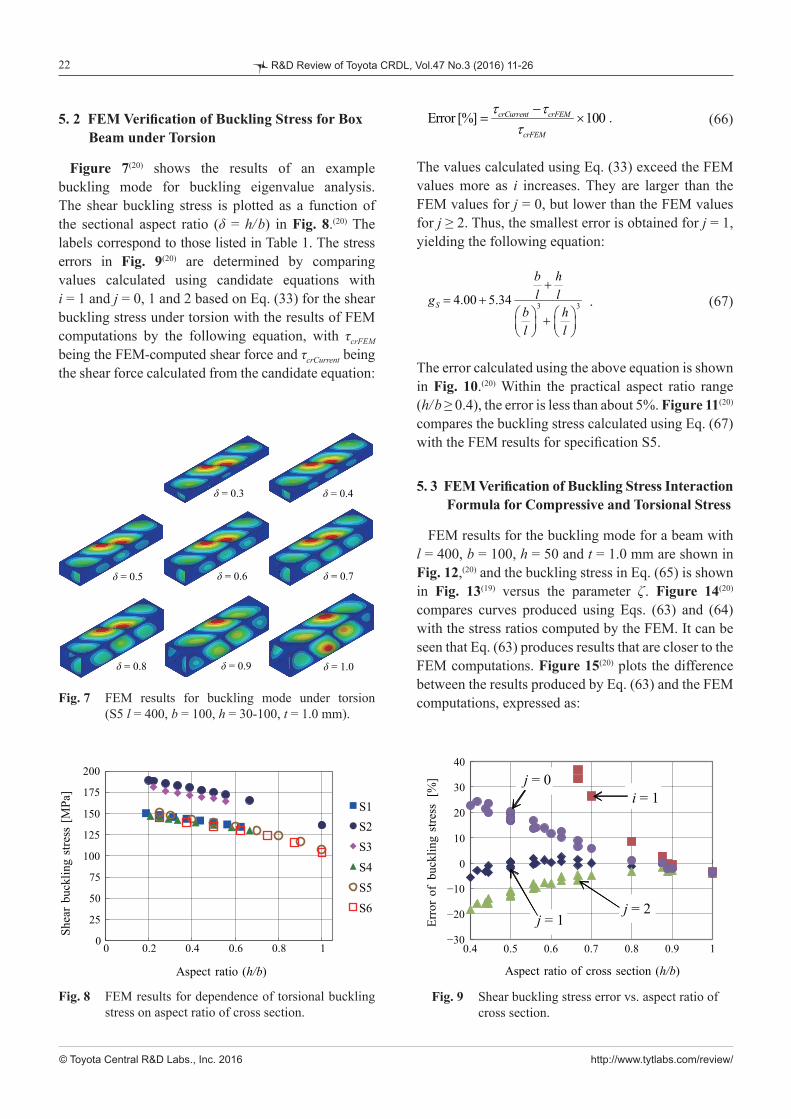
The values calculated using Eq. (33) exceed the FEM values more as i increases. They are larger than the FEM values for j = 0, but lower than the FEM values for j ≥ 2. Thus, the smallest error is obtained for j = 1, yielding the following equation:
. (67)
The error calculated using the above equation is shown in Fig. 10.(20) Within the practical aspect ratio range (h/b ≥ 0.4), the error is less than about 5%. Figure 11(20) compares the buckling stress calculated using Eq. (67) with the FEM results for specification S5.
5. 3 FEM Verification of Buckling Stress InteractionFormula for Compressive and Torsional Stress
FEM results for the buckling mode for a beam with l = 400, b = 100, h = 50 and t = 1.0 mm are shown in Fig. 12,(20) and the buckling stress in Eq. (65) is shown in Fig. 13(19) versus the parameter ζ . Figure 14(20) compares curves produced using Eqs. (63) and (64) with the stress ratios computed by the FEM. It can be seen that Eq. (63) produces results that are closer to the FEM computations. Figure 15(20) plots the difference between the results produced by Eq. (63) and the FEM computations, expressed as:
5. 2 FEM Verification of Buckling Stress for BoxBeam under Torsion
Figure 7(20) shows the results of an example buckling mode for buckling eigenvalue analysis. The shear buckling stress is plotted as a function of the sectional aspect ratio (δ = h/b) in Fig. 8.(20) The labels correspond to those listed in Table 1. The stress errors in Fig. 9(20) are determined by comparing values calculated using candidate equations with i = 1 and j = 0, 1 and 2 based on Eq. (33) for the shear buckling stress under torsion with the results of FEM computations by the following equation, with τcrFEM being the FEM-computed shear force and τcrCurrent being the shear force calculated from the candidate equation:
Fig. 9 Shear buckling stress error vs. aspect ratio of cross section.
Fig. 8 FEM results for dependence of torsional buckling stress on aspect ratio of cross section.
-30
-20
-10
0
10
20
30
40
0.4 0.5 0.6 0.7 0.8 0.9 1
Erro
r of B
uckl
ing
Stre
ss
[%]
Aspect Ratio of Cross Section (h/b)
i=1j=0
j=1j=2
−30
−20
−10
0
10
20
30
40
Erro
r of
buck
ling
stre
ss [
%]
0.4 0.5 0.6 0.7 0.8 0.9 1
Aspect ratio of cross section (h/b)
j = 1j = 2
i = 1j = 0
-30
-20
-10
0
10
20
30
40
0.4 0.5 0.6 0.7 0.8 0.9 1
Erro
r of B
uckli
ng S
tress
[%
]
Aspect Ratio of Cross Section (h/b)
i=1j=0
j=1j=2
0
25
50
75
100
125
150
175
200
0 0.2 0.4 0.6 0.8 1
Shea
r Buc
klin
g St
ress
[MPa
]
Aspect Ratio (h / b)
S2S1
S3S4S5S6
0
25
50
75
100
125
150
175
200
Shea
r bu
cklin
g st
ress
[M
Pa]
0 0.2 0.4 0.6 0.8 1
Aspect ratio (h/b)
δ=0.3
δ=0.5 δ=0.6
δ=0.4
δ=1.0
δ=0.7
δ=0.9δ=0.8
(Fig. 7)
Fig. 7 FEM results for buckling mode under torsion. (S5 l=400, b=100, h=30~100, t=1.0 mm)
δ = 0.4δ = 0.3
δ = 0.5 δ = 0.6 δ = 0.7
δ = 1.0δ = 0.9δ = 0.8
Fig. 7 FEM results for buckling mode under torsion (S5 l = 400, b = 100, h = 30-100, t = 1.0 mm).

http://www.tytlabs.com/review/
23
© Toyota Central R&D Labs., Inc. 2016
R&D Review of Toyota CRDL, Vol.47 No.3 (2016) 11-26
deviation is as large as 12%, the accuracy of Eq. (63) is not very high.
As described in Sec. 4. 4, the compressive and shear buckling stress interaction formulae Eqs. (63) and (64) can be expressed as the formula below, using the parameter c.
(69)
, (68)
where σcrFEM and τcrFEM represent the FEM computed compressive and torsional buckling stresses, respectively, and σ 'crFEM and τ 'crFEM are the buckling stress components computed from the FEM buckling eigenvalue analysis for combined compressive and torsional stress. The labels correspond to those listed in Table 1. It can be seen that the largest differences appear at about ζ = 0.4. This is the effect of the aspect ratio δ of the beam section. As δ approaches 1 and the section becomes more square, greater deviation occurs between the two sets of results. Given that this
Fig. 11 Comparison of buckling stress obtained by FEM, plate theory, and current method (S5 l = 400, b = 100, h = 40-100, t = 1.0 mm).
Fig. 13 Dependence of buckling stress on stress ratio as determined by FEM (C3 l = 400, b = 100, h = 50, t = 1.0 mm, ζ = 0.0-1.0).
Fig. 10 Dependence of error in shear buckling stress obtained using Eq. (67) on aspect ratio of cross section.
Fig. 12 Buckling modes determined by FEM (l = 400, b = 100, h = 50, t = 1.0 mm, ζ = 0.0-1.0).
0
20
40
60
80
100
120
140
160
0.4 0.5 0.6 0.7 0.8 0.9 1
Buc
klin
g St
ress
[MPa
]
Aspect Ratio (h / b)
Plate Theory
FEM
Current
0
20
40
60
80
100
120
140
160
Buc
klin
g st
ress
[M
Pa]
0.4 0.5 0.6 0.7 0.8 0.9 1
Aspect ratio (h/b)
Plate theory
FEM
Current
0
20
40
60
80
100
120
140
0 0.2 0.4 0.6 0.8 1
Buc
klin
g St
ress
[MPa
]
ζ
τ'cr
σ'cr
0
20
40
60
80
100
120
140
Buc
klin
g st
ress
[M
Pa]
0 0.2 0.4 0.6 0.8 1
ζ
τ 'cr
σ 'cr
-10
-5
0
5
0.4 0.5 0.6 0.7 0.8 0.9 1
Erro
r of B
uckl
ing
Stre
ss [%
]
Aspect Ratio (h/b) of Cross Section
−10
−5
0
5
Erro
r of
buc
klin
g st
ress
[%
]
0.4 0.5 0.6 0.7 0.8 0.9 1
Aspect ratio (h/b) of cross section
ζ=0.4
ζ=0.5 ζ=0.6
ζ=0.3
ζ=0.8 ζ=0.9 ζ=1.0
ζ=0.7
ζ=0.0 ζ=0.1
ζ=0.2
ζ = 0.0 ζ = 0.1
ζ = 0.4ζ = 0.3ζ = 0.2
ζ = 0.5 ζ = 0.6
ζ = 0.9ζ = 0.8 ζ = 1.0
ζ = 0.7
http://www.tytlabs.com/review/
24
© Toyota Central R&D Labs., Inc. 2016
R&D Review of Toyota CRDL, Vol.47 No.3 (2016) 11-26
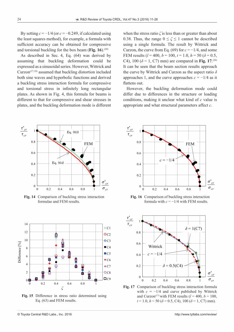
when the stress ratio ζ is less than or greater than about 0.38. Thus, the range 0 ≤ ζ ≤ 1 cannot be described using a single formula. The result by Wittrick and Curzon, the curve from Eq. (69) for c = −1/4, and some FEM results (l = 400, b = 100, t = 1.0, h = 50 (δ = 0.5, C4), 100 (δ = 1, C7) mm) are compared in Fig. 17.(20) It can be seen that the beam section results approach the curve by Wittrick and Curzon as the aspect ratio δ approaches 1, and the curve approaches c = −1/4 as it flattens out.
However, the buckling deformation mode could differ due to differences in the structure or loading conditions, making it unclear what kind of c value is appropriate and what structural parameters affect c.
By setting c = −1/4 (or c = −0.249, if calculated using the least squares method), for example, a formula with sufficient accuracy can be obtained for compressive and torsional buckling for the box beam (Fig. 16).(20)
As described in Sec. 4, Eq. (64) was derived by assuming that buckling deformation could be expressed as a sinusoidal series. However, Wittrick and Curzon(17,18) assumed that buckling distortion included both sine waves and hyperbolic functions and derived a buckling stress interaction formula for compressive and torsional stress in infinitely long rectangular plates. As shown in Fig. 4, this formula for beams is different to that for compressive and shear stresses in plates, and the buckling deformation mode is different
Fig. 17 Comparison of buckling stress interaction formula with c = −1/4 and curve published by Wittrick and Curzon(17) with FEM results (l = 400, b = 100, t = 1.0, h = 50 (δ = 0.5, C4), 100 (δ = 1, C7) mm).
Fig. 16 Comparison of buckling stress interaction formula with c = −1/4 with FEM results.
0
0.2
0.4
0.6
0.8
1
0 0.2 0.4 0.6 0.8 1
'cr
cr
σσ
'cr
cr
ττ
1 4c = −Wittrick
δ=1(C7)
δ=0.5(C4)
τ 'crτcr
σ 'crσcr0 0.2 0.4 0.6 0.8 1
0
0.2
0.4
0.6
0.8
1
δ = 1(C7)
δ = 0.5(C4)
c = −1/4
0
0.2
0.4
0.6
0.8
1
0 0.2 0.4 0.6 0.8 1
FEM
c=-1/4
'cr
cr
σσ
'cr
cr
ττ
τ 'crτcr
σ 'crσcr
c = −1/4
0
0.2
0.4
0.6
0.8
1
0 0.2 0.4 0.6 0.8 1
Fig. 15 Difference in stress ratio determined using Eq. (63) and FEM results.
Fig. 14 Comparison of buckling stress interaction formulae and FEM results.
0
0.2
0.4
0.6
0.8
1
0 0.2 0.4 0.6 0.8 1
FEM
'cr
cr
σσ
'cr
cr
ττ
Eq. (64)
Eq. (63)τ 'crτcr
σ 'crσcr0 0.2 0.4 0.6 0.8 1
0
0.2
0.4
0.6
0.8
1
0
2
4
6
8
10
12
14
0 0.2 0.4 0.6 0.8 1
Diff
eren
ce [%
]
ζ
C4
C5
C6
C7
C1
C2
C3
C8
C90 0.2 0.4 0.6 0.8 1
ζ
0
2
4
6
8
10
12
14
Diff
eren
ce [%
]
0
2
4
6
8
10
12
14
0 0.2 0.4 0.6 0.8 1
Diff
eren
ce [%
]
ζ
C4
C5
C6
C7
C1
C2
C3
C8
C9

http://www.tytlabs.com/review/
25
© Toyota Central R&D Labs., Inc. 2016
R&D Review of Toyota CRDL, Vol.47 No.3 (2016) 11-26
relation to a patient joint research over the years in spite of slow progress.
References
(1) Timoshenko, S. P., Theory of Elastic Stability, 2nd Ed. (1961), 541p., McGraw-Hill.
(2) Hayashi, T., Keikouzou no Riron to sono Ouyou (Jou) (in Japanese) (1966), 194p., Nihon Kagaku Gijutsu Renmei.
(3) Column Research Committee of Japan, Handbook of Structural Stability (1971), 1048p., Corona Pub. Co.
(4) Ziemian , R. D., Guide to Stability Design Criteria for Metal Structures, 6th Ed. (2010), pp. 128-145, John Wiley & Sons, Inc.
(5) Kobayashi, S., Koukuuki Kouzou Rikigaku, Zouhoshinpan (in Japanese) (2014), pp. 141-148, Pleiades Pub. Co.
(6) Sakai, T., “On the Relation between Energy and Galerkin’s Methods for Problems of Mechanics”, Bull. Fac. Eng., Hokkaido University (in Japanese), Vol. 1S (1948), pp. 167-185.
(7) Akasaka, T. and Yoshida, H., Zairyo oyobi Kozo Gijutsusha no tameno Jitsuyo Enerugiho (in Japanese) (2000), 273p., Youkendou.
(8) von Karman, T., Sechler, E. E. and Donnell, L. H., “The Strength of Thin Plates in Compression”,
Trans. ASME, Vol. 54 (1932), pp. 53-56.(9) Yu, W.-W., Cold-formed Steel Design, 3rd Ed. (2000),
756p., John Wiley & Sons, Inc.(10) AISI/CARS 2002, GAS (Geometric Analysis of
Sections) (2002), American Iron and Steel Institute & Auto/Steel Partnership, (CD-ROM).
(11) Kobayashi, S. and Kondou, K., Dansei Rikigaku (in Japanese) (1987), 305p., Baifuukan.(12) Byon, O. and Uemura, M., “Post-buckling Behaviros
of Flat Plates under Axial Compression, 1st Rep., Discussion of Secondary Buckling Values by Analytical Method”, Rep. Aerosp. Res. Inst. Univ. Tokyo
(in Japanese), Vol. 12, No. 2 (1976), pp. 477-496.(13) Kuranishi, M., “Several Kinds of Elastic Instability
of Thin Plane-walled Struts under Axial Compressive Load, and Condition of Minimum Weight”, J. Soc. Naval Architects (in Japanese), Vol. 1935, No. 56 (1935), pp. 127-143.
(14) Kuranishi, M., “The Wall Buckling Strength of Thin Plane Walled Struts under Axial Compressive Load, 1st Report”, J. Jpn. Soc. Aeronaut. Eng. (in Japanese), Vol. 2, No. 3 (1935), pp. 55-86.
(15) Kuranishi, M., “The Wall Buckling Strength of Thin Plane Walled Struts under Axial Compressive Load, 2nd Report”, J. Jpn. Soc. Aeronaut. Eng.
(in Japanese), Vol. 2, No. 4 (1935), pp. 259-284.(16) Kuranishi, M., “The Wall Buckling Strength of Thin
Plane Walled Struts under Axial Compressive Load, 3rd Report”, J. Jpn. Soc. Aeronaut. Eng. (in Japanese), Vol. 2, No. 5 (1935), pp. 485-508.
6. Conclusion
This report began by discussing simplified methods for determining the shear buckling stress under torsion for box beams. An equation for approximating the shear buckling stress was proposed, and was verified for accuracy against the results of a buckling eigenvalue analysis using FEM. Next, buckling stress interaction formulae were introduced for a combination of an axial compressive force and a torsional torque on a thin-walled box beam. First, a buckling stress interaction formulae was derived based on the energy method for a single plate. Based on this result, an interaction formula for compressive and torsional buckling stress was proposed, and its accuracy was verified by comparing to the results of an FEM buckling eigenvalue analysis. The conclusions were as follows:(1) Based on a buckling eigen equation derived using the energy method, the conventional shear buckling stress equation and buckling stress coefficient were rewritten to enable simultaneous and symmetrical treatment of widths for both horizontal and vertical plates in order to propose an approximation equation for determining the shear stress under torsional buckling in a box beam. Based on a comparison with the FEM results, the proposed approximation equation was found to exhibit an error of less than about 5% for sectional aspect ratios of 0.4-1.0, which is an acceptable level of accuracy.(2) Assuming that the buckling mode was sinusoidal, approximating the buckling eigen equation obtained with the energy method using low-order terms allowed us to derive a buckling stress interaction formula for plates under combined loads. There were demonstrated similarities between the formulae obtained, and they could be related through a single parameter. The proposed formulae for compressive and torsional buckling stress in box beams were found to differ depending upon the load ratio and sectional aspect ratio.
Acknowledgement
Valuable outcome in this report is the results obtained by the joint research with Toyota Motor Corporation. We express respectful gratitude to Mr. Tsutomu Hamabe, Mr. Norihisa Aoki and Mr. Hideo Takeda of Toyota Motor Corporation in

http://www.tytlabs.com/review/
26
© Toyota Central R&D Labs., Inc. 2016
R&D Review of Toyota CRDL, Vol.47 No.3 (2016) 11-26
(17) Wittrick, W. H. and Curzon, P. L. V., “Stability Functions for the Local Buckling of Thin-walled Structures in Bending and Compression”, Aeronaut. Quarterly (1968), pp. 327-351.
(18) Wittrick, W. H. and Curzon, P. L. V., “Local Buckling of Long Polygonal Tubes in Combined Compression and Torsion”, Int. J. Mech. Sci., Vol. 10 (1968),
pp. 849-857.(19) Furusu, K., Amago, T., Nakagawa, T., Hamabe, T. and
Aoki, N., “Buckling Stress Relation Equations of Box Beam under Compression and Torsion”, Trans. JSME
(in Japanese), Vol. 80, No. 816 (2014), DOI : 10.1299/transjsme.2014smm0219.(20) Furusu, K., “Studies on the Buckling of the Box Beam
Composed of Thin Plates”, Dr. Thesis, Seikei University (in Japanese) (2015), 122p.(21) Iguchi, S., “Die Knickung der Rechtechckigen Platte
durch Schubkrafte”, Ingenieur-archiv, Vol. 9 (1938), pp. 1-12.
(22) Iguchi, S., “Die Knickung der Vierseitig Eingespannten Rechteckigen Platte durch Schubkrafte”, Proc. Physico-mathematical Soc. Jpn., 3rd, Vol. 20 (1938), pp. 814-832.
(23) Chwalla, E., “Beitrag zur Stabilitatstheorie des Stegbleches Vollwandiger Trager”, Der Stahlbau, Vol. 9 (1936), pp. 161-166.
(24) Johnson, Jr. A. E. and Buchert, K. P., “Critical Combinations of Bending, Shear, and Transverse Compressive Stresses for Bucking of Infinitely Long Flat Plates”, NACA Technical Note, No. 2536 (1951).
Figs. 1, 5 and 13Reprinted from Trans. JSME (in Japanese), Vol. 80, No. 816(2014), Furusu, K., Amago, T., Nakagawa, T., Hamabe, T. and Aoki, N., Buckling Stress Relation Equations of Box Beam under Compression and Torsion, © 2014 The Japan Society of Mechanical Engineers.
Katsuya Furusu Research Field: - Structural Analysis Academic Degree: Dr.Eng. Academic Societies: - The Japan Society of Mechanical Engineers - Society of Automotive Engineers of Japan
Tatsuyuki Amago Research Fields: - Design by the Structural Analysis - Spot Welding Academic Societies: - The Japan Society of Mechanical Engineers - Society of Automotive Engineers of Japan - Japan Welding Society
Toshiaki Nakagawa Research Fields: - Mass Management - Noise and Vibration Academic Degree: Dr.Eng. Academic Societies: - The Japan Society of Mechanical Engineers - Society of Automotive Engineers of Japan