Embed Size (px)
Citation preview
Elasto-plastic stress analysis of aluminum metal-matrixcomposite laminated plates under in-plane loading
O. Saymana,*, H. Akbuluta, C. Meric° b
aDepartment of Mechanical Engineering, Dokuz EyluÈl University, Bornova, Izmir, TurkeybDepartment of Mechanical Engineering, Celal Bayar University, Manisa, Turkey
Received 2 February 1998; accepted 3 March 1999
Abstract
The study presents an elasto-plastic stress analysis of symmetric and antisymmetric cross-ply, angle-ply laminatedmetal-matrix composite plates. Long stainless steel ®ber reinforced aluminum metal-matrix composite layer ismanufactured by using moulds under the action of 30 MPa pressure and heating up to 6008C. A laminated plate
consists of four metal-matrix layers bonded symmetrically or antisymmetrically. The ®rst-order shear deformationtheory and nine-node Lagrangian ®nite element is used. The in-plane load is increased gradually. # 2000 ElsevierScience Ltd. All rights reserved.
Keywords: Metal matrix composite; Elasto-plastic analysis; Finite element method; Laminated plate
1. Introduction
Metal-matrix composites consist of a ductile, usually
low strength matrix reinforced with elastic, brittle or
ductile and strong ®bers. The strength of the ®ber andthe ductility of the matrix provide a new material with
superior properties.
Plastic deformations and residual stresses are im-
portant in composite laminated plates. Residual stres-
ses are used to raise the yield point of the plate.Bahaei-El-Din and Dvorak [1] have investigated the
elastic±plastic behavior of symmetric metal-matrix
composite laminates for the case of in-plane mechan-ical loading. In this study, aluminum matrix is re-
inforced by boron ®bers. Metal-matrix composites
consist of a ductile, usually low strength matrix re-inforced with elastic brittle, or ductile strong ®bers
which provide a new material with superior properties
such as high strength and sti�ness, low density and re-sistance to corrosion, high creep and fatigue properties[2±5]. Karakuzu and OÈ zcan [6] have given an exact sol-
ution to the elasto-plastic stress analysis of an alumi-num metal-matrix composite beam reinforced by steel®bers.
Linear or nonlinear ®nite element method can beused to analyze the laminated composites [7±10]. Inthis study, aluminum metal-matrix composite lami-nated plates reinforced by steel ®bers are manufactured
and analyzed by using the ®nite element technique.
2. Mathematical formulation
The laminated plate of constant thickness is com-posed of orthotropic layers bonded symmetrically or
antisymmetrically about the middle surface of theplate. In the solution of this problem, the Cartesian
Computers and Structures 75 (2000) 55±63
0045-7949/00/$ - see front matter # 2000 Elsevier Science Ltd. All rights reserved.
PII: S0045-7949(99 )00086-3
www.elsevier.com/locate/compstruc
* Corresponding author.
coordinates are used where the middle surface of the
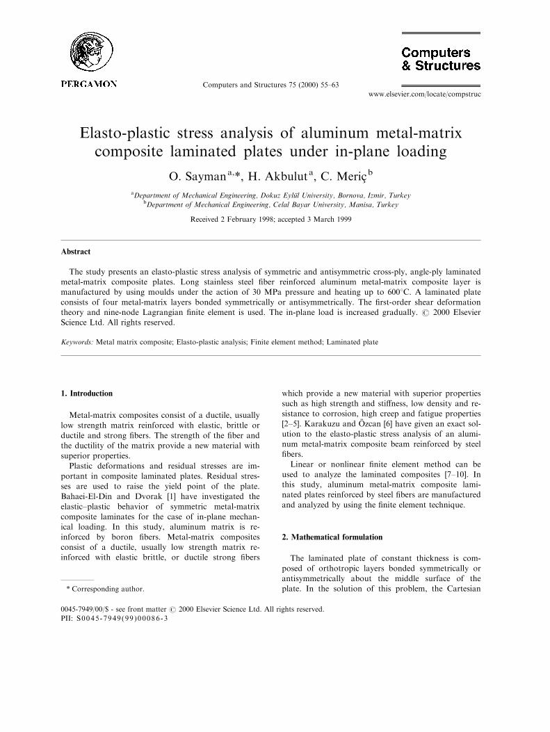
plate coincides with the x±y plane, as shown in Fig. 1.Here we use the theory of plates with transverse
shear deformations theory which uses the assumptionthat particles of the plate originally on a line that is
normal to the undeformed middle surface remain on astraight line during deformations, but this line is notnecessarily normal to the deformed middle surface. By
using this assumption the displacement components ofa point with coordinates x, y, z for small deformationsare:
u�x,y,z� � u0�x,y� � zcx�x,y�
v�x,y,z� � v0�x,y� ÿ zcy�x,y�
w�x,y,z� � w�x,y� �1�
where u0, v0 and w are the displacements at any pointof the middle surface, and cx,cy are the rotations of
normals to midplane about the y and x axes, respect-
ively.The bending strains vary linearly through the plate
thickness, whereas shear strains are assumed to be con-stant through the thickness as
8<:exeygxy
9=; ���������������
@u0@x
@v0@y
@u0@y� @v0@x
��������������� z
��������������
@cx
@x
@cy
@y
@cx
@yÿ @cy
@x
��������������or
�������exeygxy
������� ���������e0xe0y
g0xy
��������� z
������Kx
Ky
Kxy
������
���� gyzgxz
���� ����������@w
@yÿ cy
@w
@x� cx
��������� �2�
The total potential energy of a laminated plate under
static loadings is given as
P � Ub �Us � V �3�
where Ub is the strain energy of bending, Us is thestrain energy of shear and V represents potentialenergy of external forces. They are as
Fig. 1. Loading of laminated plate.
Fig. 2. The production of composite layer.
O. Sayman et al. / Computers and Structures 75 (2000) 55±6356
Ub � 1
2
�h=2ÿh=2
� �A
ÿsxex � syey � txygxy
�dA
�dz
Us � 1
2
�h=2ÿh=2
� �A
ÿtxzgxz � tyzgyz
�dA
�dz
V � ÿ�A
wp dAÿ�@R
��N
b
nu0n � �N
b
s u0s
�ds �4�
where dA � dx dy, p is the transverse loading per unitarea and �N
b
n and �Nb
s are the in-plane loads applied on
the boundary @R:
3. Production of laminated plates
The composite layer consists of stainless steel ®berand aluminum matrix. The production has been rea-
lized by using moulds which consist of upper andlower parts. Electrical resistance has been used to heatthe moulds and material which are insulated, as illus-trated in Fig. 2.
The hydraulic press has been used to obtain a press-ure of 30 MPa to the upper mould. Manufacturing sethas been heated to 6008C. In these conditions, the
yield strength of aluminum is exceeded and goodbonding between matrix and ®ber has been realized.The mechanical properties, yield points and plastic
parameters are given in Table 1. It is assumed that theyield point Z (in the z direction) is equal to the yieldpoint Y (in the y direction), the yield points of txz, tyzare equal to S. The von Mises and Tresca criteria are
used generally for isotropic materials. Huber±Misesyield criterion has been generalized by Hill for aniso-tropic metals [14]. It is more appropriate to use
Huber±Mises or Tsai±Hill failure criteria for anisotro-pic metals, since their yield points are di�erent inlongitudinal and lateral directions. The di�erence
between the numerical results for the residual stressesin the symmetric cross-ply ([08/908]2) laminated plate
obtained for Huber±Mises and Tsai±Hill criteria isfound as 0.8% as shown in Table 2. The Tsai±Hill cri-terion is used as a yield criterion [13]. Four layers have
been bonded to form a laminated plate symmetricallyor antisymmetrically by using a pressure of 30 MPaand heating up to 6008C. The stress±strain relation in
plastic region is given as
s � s0 � kenp
4. Finite element analysis
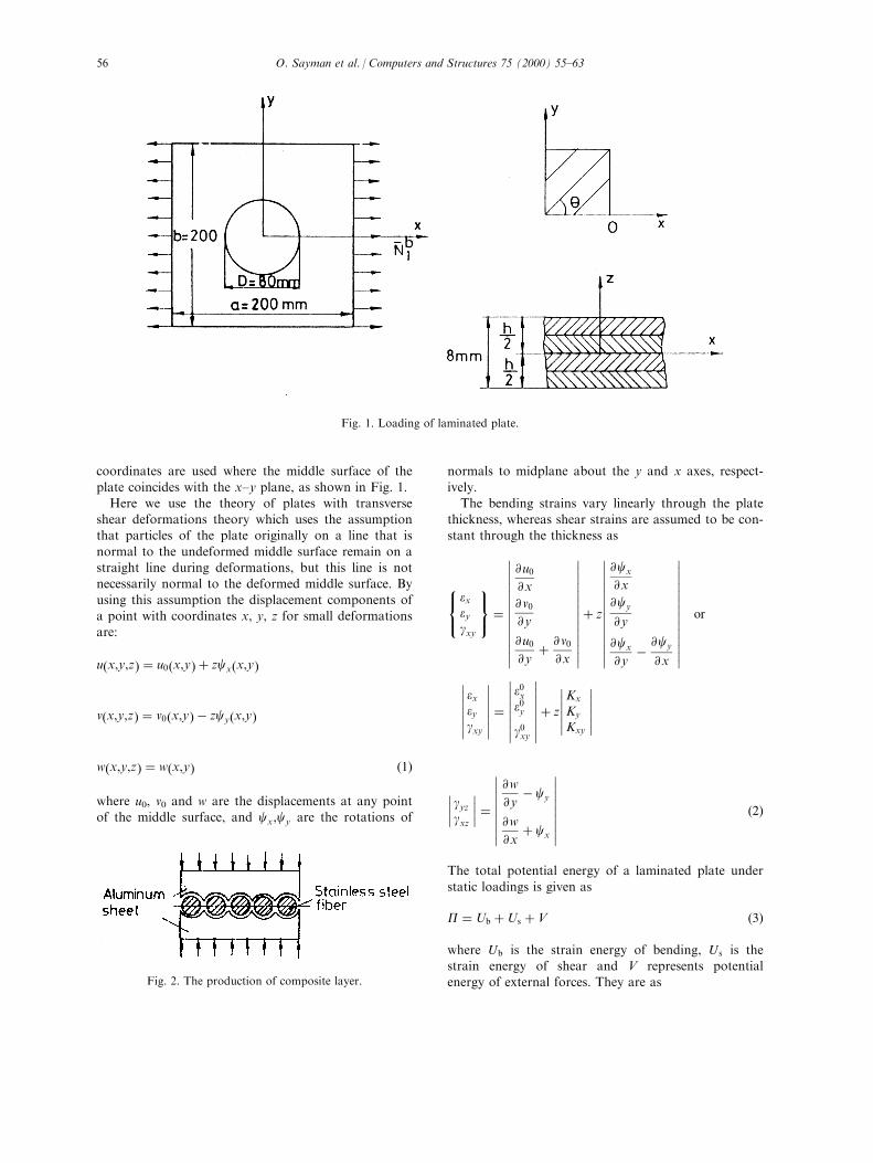
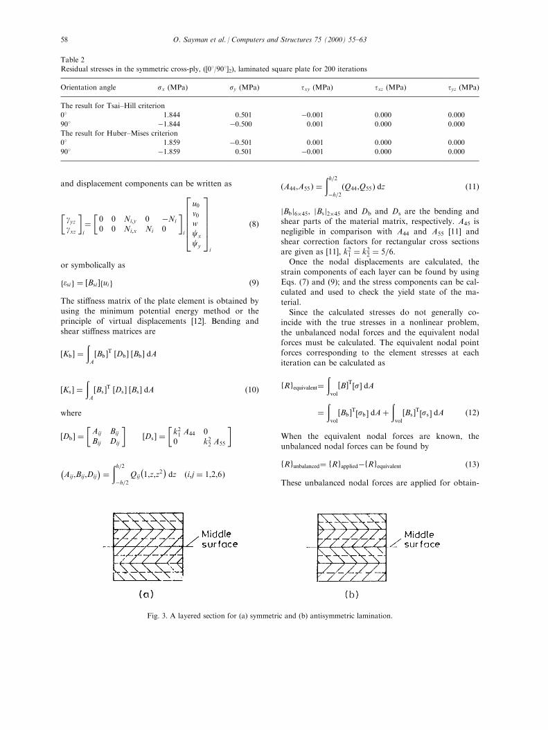
The symmetric or antisymmetric laminated plate iscomposed of four layers. A typical ®nite element for a
symmetric and an antisymmetric lamination is dividedinto eight imaginary layers for obtaining the ®nite el-ement results more accurately, as shown in Fig. 3.
The nine-node ®nite element is used in this study.The displacement ®eld can be expressed in the follow-ing matrix form:
�d� �
266666664
u0
v0
w
cx
cy
377777775 �Xni�1
26666664Ni 0 0 0 0
0 Ni 0 0 0
0 0 Ni 0 0
0 0 0 Ni 0
0 0 0 0 Ni
37777775266666664
u0
v0
w
cx
cy
377777775i
�5�
in which n is the total number of nodes and Ni is theshape function at node i.The relationship between strains and displacements
can be written in the matrix form:2666666664
e0xe0y
g0xyKx
Ky
Kxy
3777777775i
�
26666664Ni,x 0 0 0 00 Ni,y 0 0 0Ni,y Ni,x 0 0 00 0 0 Ni,x 00 0 0 0 ÿNi,y
0 0 0 Ni,y ÿNi,x
37777775i
2666664u0v0wcx
cy
3777775i
�6�
or symbolically as
febi g � �Bbi � �ui � �7�
in which i is the node number, and commas representpartial derivatives.The relationship between the transverse shear strains
Table 1
The measured mechanical properties and yield points of a
layer
Mechanical properties
E1 86 GPa
E2 74 GPa
G12 32 GPa
n12 0.30
Yield strengths and parameters
Axial strength, X 228.3 MPa
Transverse strength, Y 24.2 MPa
Shear strength, S 47.6 MPa
Hardening parameter, k 1254 MPa
Strain hardening parameter, n 0.7
O. Sayman et al. / Computers and Structures 75 (2000) 55±63 57
and displacement components can be written as
�gyzgxz
�i
��0 0 Ni,y 0 ÿNi
0 0 Ni,x Ni 0
�i
2666664u0v0wcx
cy
3777775i
�8�
or symbolically as
fesi g � �Bsi �fui g �9�
The sti�ness matrix of the plate element is obtained byusing the minimum potential energy method or theprinciple of virtual displacements [12]. Bending and
shear sti�ness matrices are
�Kb � ��A
�Bb �T �Db � �Bb � dA
�Ks � ��A
�Bs �T �Ds � �Bs � dA �10�
where
�Db � ��Aij Bij
Bij Dij
��Ds � �
�k21 A44 00 k22 A55
�
ÿAij,Bij,Dij
� � �h=2ÿh=2
Qij
ÿ1,z,z2
�dz �i,j � 1,2,6�
�A44,A55 � ��h=2ÿh=2�Q44,Q55 � dz �11�
jBbj6�45, jBsj2�45 and Db and Ds are the bending andshear parts of the material matrix, respectively. A45 is
negligible in comparison with A44 and A55 [11] andshear correction factors for rectangular cross sectionsare given as [11], k21 � k22 � 5=6:Once the nodal displacements are calculated, the
strain components of each layer can be found by usingEqs. (7) and (9); and the stress components can be cal-culated and used to check the yield state of the ma-
terial.Since the calculated stresses do not generally co-
incide with the true stresses in a nonlinear problem,
the unbalanced nodal forces and the equivalent nodalforces must be calculated. The equivalent nodal pointforces corresponding to the element stresses at each
iteration can be calculated as
fRgequivalent��
vol
�B�T�s� dA
��
vol
�Bb �T�sb � dA��
vol
�Bs �T�ss � dA �12�
When the equivalent nodal forces are known, theunbalanced nodal forces can be found by
fRgunbalanced� fRgappliedÿfRgequivalent �13�
These unbalanced nodal forces are applied for obtain-
Table 2
Residual stresses in the symmetric cross-ply, ([08/908]2), laminated square plate for 200 iterations
Orientation angle sx (MPa) sy (MPa) txy (MPa) txz (MPa) tyz (MPa)
The result for Tsai±Hill criterion
08 1.844 0.501 ÿ0.001 0.000 0.000
908 ÿ1.844 ÿ0.500 0.001 0.000 0.000
The result for Huber±Mises criterion
08 1.859 ÿ0.501 0.001 0.000 0.000
908 ÿ1.859 0.501 ÿ0.001 0.000 0.000
Fig. 3. A layered section for (a) symmetric and (b) antisymmetric lamination.
O. Sayman et al. / Computers and Structures 75 (2000) 55±6358
ing increments in the solution and must satisfy theconvergence tolerance in a nonlinear analysis. Thedi�erence between the plastic and elastic solution gives
the residual stresses. The residual stresses may increasethe possibility of failure of the laminated plates. In thissolution 216 nodes and 48 elements are used.
5. Numerical results and discussions
The laminated plate is assumed to be under uniformaxial in-plane loads along the rectangular edges and
the circular hole is unloaded. The laminated plates arecomposed of four orthotropic and generally orthotro-pic layers bonded in symmetric or antisymmetric form.
Loading is gradually increased up to plastic zone
which is not allowed to be very large. In the iterative
solution, the overall sti�ness matrix of the laminated
plate is the same at each loading step. The in-plane
load �Nx� is increased by 0.08 N/mm per step.
One quarter of the plate is enough to ®nd the expan-
sion of the plastic zone and the residual stresses in the
cross-ply symmetric laminated plate ([08/908]2) withouta hole. In this solution the plastic zone expands along
the layers of orientation angle which is 908 but the
other one is elastic. The in-plane load, Nx is increased
from 210.72 to 226.72 N/mm for 200 iterations. Re-
sidual stress components are given in Table 2.
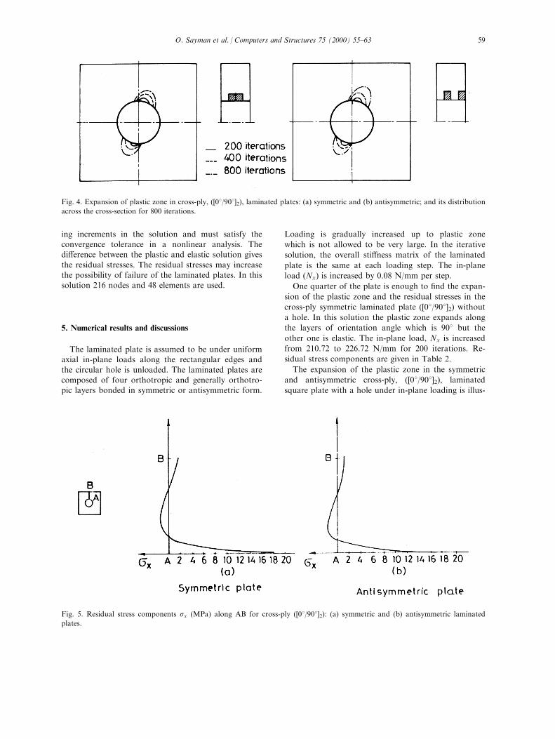
The expansion of the plastic zone in the symmetric
and antisymmetric cross-ply, ([08/908]2), laminated
square plate with a hole under in-plane loading is illus-
Fig. 4. Expansion of plastic zone in cross-ply, ([08/908]2), laminated plates: (a) symmetric and (b) antisymmetric; and its distribution
across the cross-section for 800 iterations.
Fig. 5. Residual stress components sx (MPa) along AB for cross-ply ([08/908]2): (a) symmetric and (b) antisymmetric laminated
plates.
O. Sayman et al. / Computers and Structures 75 (2000) 55±63 59
trated in Fig. 4, for simply supported condition. In the
layer of 908 orientation, for 400 iteration the residual
stress component sx along AB is given in Fig. 5.
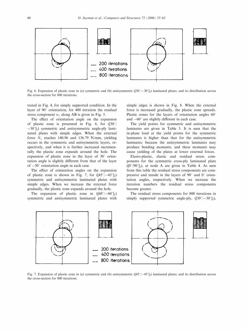
The e�ect of orientation angle on the expansion
of plastic zone is presented in Fig. 6, for ([308/ÿ308]2) symmetric and antisymmetric angle-ply lami-
nated plates with simple edges. When the external
force Nx reaches 140.96 and 136.79 N/mm, yielding
occurs in the symmetric and antisymmetric layers, re-
spectively, and when it is further increased incremen-
tally the plastic zone expands around the hole. The
expansion of plastic zone in the layer of 308 orien-
tation angle is slightly di�erent from that of the layer
of ÿ308 orientation angle in each case.
The e�ect of orientation angles on the expansion
of plastic zone is shown in Fig. 7, for ([458/ÿ458]2)symmetric and antisymmetric laminated plates with
simple edges. When we increase the external force
gradually, the plastic zone expands around the hole.
The expansion of plastic zone in ([608/ÿ608]2)symmetric and antisymmetric laminated plates with
simple edges is shown in Fig. 8. When the external
force is increased gradually, the plastic zone spreads.
Plastic zones for the layers of orientation angles 608and ÿ608 are slightly di�erent in each case.
The yield points for symmetric and antisymmetric
laminates are given in Table 3. It is seen that the
in-plane load at the yield points for the symmetric
laminates is higher than that for the antisymmetric
laminates; because the antisymmetric laminates may
produce bending moments, and these moments may
cause yielding of the plates at lower external forces.
Elasto-plastic, elastic and residual stress com-
ponents for the symmetric cross-ply laminated plate
([08/908]2), at node A are given in Table 4. As seen
from this table the residual stress components are com-
pressive and tensile in the layers of 908 and 08 orien-
tation angles, respectively. When we increase the
iteration numbers the residual stress components
become greater.
The residual stress components for 800 iterations in
simply supported symmetric angle-ply, ([308/ÿ308]2),
Fig. 6. Expansion of plastic zone in (a) symmetric and (b) antisymmetric ([308/ÿ308]2) laminated plates; and its distribution across
the cross-section for 800 iterations.
Fig. 7. Expansion of plastic zone in (a) symmetric and (b) antisymmetric ([458/ÿ458]2) laminated plates; and its distribution across
the cross-section for 800 iterations.
O. Sayman et al. / Computers and Structures 75 (2000) 55±6360
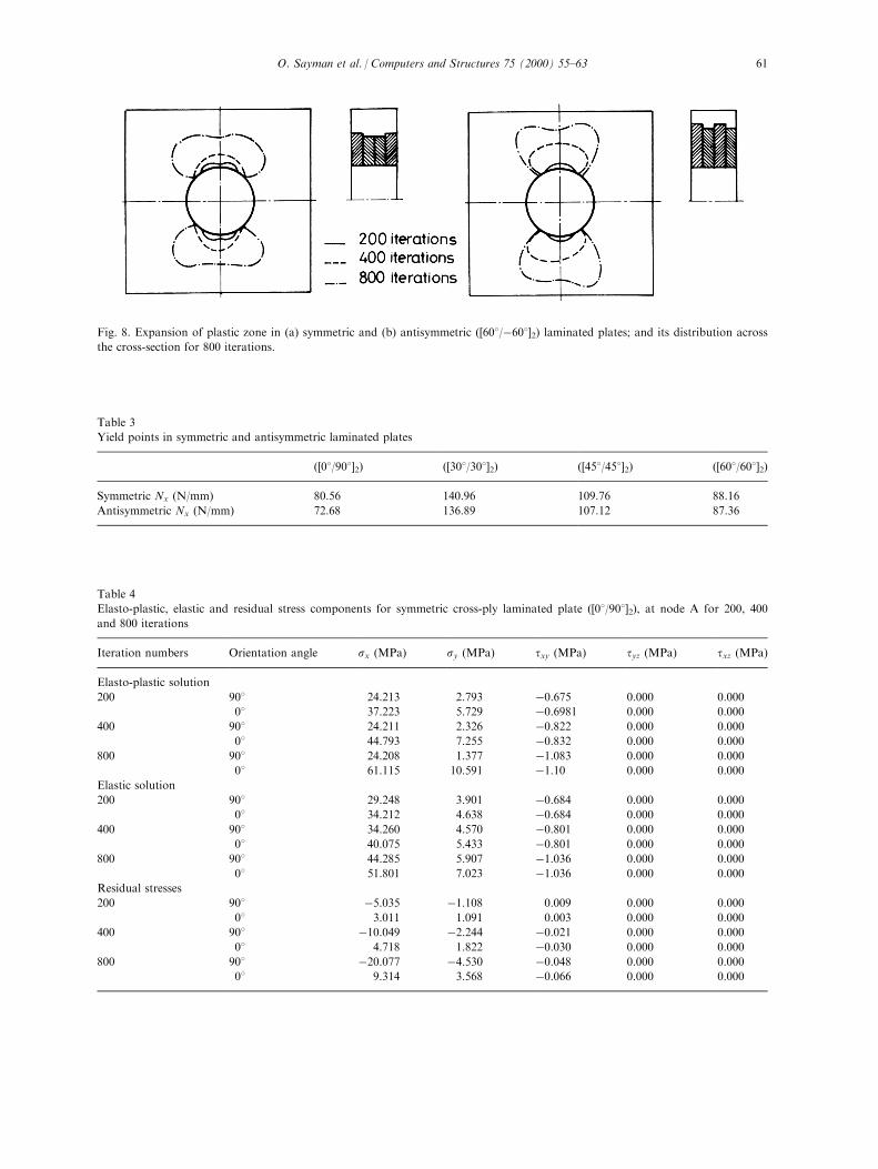
Fig. 8. Expansion of plastic zone in (a) symmetric and (b) antisymmetric ([608/ÿ608]2) laminated plates; and its distribution across
the cross-section for 800 iterations.
Table 3
Yield points in symmetric and antisymmetric laminated plates
([08/908]2) ([308/308]2) ([458/458]2) ([608/608]2)
Symmetric Nx (N/mm) 80.56 140.96 109.76 88.16
Antisymmetric Nx (N/mm) 72.68 136.89 107.12 87.36
Table 4
Elasto-plastic, elastic and residual stress components for symmetric cross-ply laminated plate ([08/908]2), at node A for 200, 400
and 800 iterations
Iteration numbers Orientation angle sx (MPa) sy (MPa) txy (MPa) tyz (MPa) txz (MPa)
Elasto-plastic solution
200 908 24.213 2.793 ÿ0.675 0.000 0.000
08 37.223 5.729 ÿ0.6981 0.000 0.000
400 908 24.211 2.326 ÿ0.822 0.000 0.000
08 44.793 7.255 ÿ0.832 0.000 0.000
800 908 24.208 1.377 ÿ1.083 0.000 0.000
08 61.115 10.591 ÿ1.10 0.000 0.000
Elastic solution
200 908 29.248 3.901 ÿ0.684 0.000 0.000
08 34.212 4.638 ÿ0.684 0.000 0.000
400 908 34.260 4.570 ÿ0.801 0.000 0.000
08 40.075 5.433 ÿ0.801 0.000 0.000
800 908 44.285 5.907 ÿ1.036 0.000 0.000
08 51.801 7.023 ÿ1.036 0.000 0.000
Residual stresses
200 908 ÿ5.035 ÿ1.108 0.009 0.000 0.000
08 3.011 1.091 0.003 0.000 0.000
400 908 ÿ10.049 ÿ2.244 ÿ0.021 0.000 0.000
08 4.718 1.822 ÿ0.030 0.000 0.000
800 908 ÿ20.077 ÿ4.530 ÿ0.048 0.000 0.000
08 9.314 3.568 ÿ0.066 0.000 0.000
O. Sayman et al. / Computers and Structures 75 (2000) 55±63 61
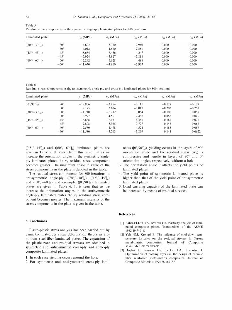
([458/ÿ458]2) and ([608/ÿ608]2) laminated plates are
given in Table 5. It is seen from this table that as weincrease the orientation angles in the symmetric angle-ply laminated plates the sx residual stress component
becomes greater. The maximum absolute value of thestress components in the plate is denoted in the table.The residual stress components for 800 iterations in
antisymmetric angle-ply, ([308/ÿ308]2), ([458/ÿ458]2)and ([608/ÿ608]2) and cross-ply ([08/908]2) laminatedplates are given in Table 6. It is seen that as we
increase the orientation angles in the antisymmetricangle-ply laminated plates the sx residual stress com-ponent becomes greater. The maximum intensity of thestress components in the plate is given in the table.
6. Conclusions
Elasto-plastic stress analysis has been carried out byusing the ®rst-order shear deformation theory in alu-
minium±steel ®ber laminated plates. The expansion ofthe plastic zone and residual stresses are obtained insymmetric and antisymmetric cross-ply and angle-ply
composite laminated plates.
1. In each case yielding occurs around the hole.2. For symmetric and antisymmetric cross-ply lami-
nates ([08/908]2), yielding occurs in the layers of 908orientation angle and the residual stress �Nx� iscompressive and tensile in layers of 908 and 08orientation angles, respectively, without a hole.
3. The orientation angle y a�ects the yield points oflaminated plates.
4. The yield point of symmetric laminated plates is
higher than that of the yield point of antisymmetriclaminated plates.
5. Load carrying capacity of the laminated plate can
be increased by means of residual stresses.
References
[1] Bahei-El-Din YA, Dvorak GJ. Plasticity analysis of lami-
nated composite plates. Transactions of the ASME
1982;49:740±6.
[2] Yeh NM, Krempl E. The in¯uence of cool-down tem-
perature histories on the residual stresses in ®brous
metal-matrix composites. Journal of Composite
Materials 1993;27:973±95.
[3] Doghri I, Jansson DS, Leckie FA, Lemaitre J.
Optimization of coating layers in the design of ceramic
®ber reinforced metal-matrix composites. Journal of
Composite Materials 1994;28:167±87.
Table 5
Residual stress components in the symmetric angle-ply laminated plates for 800 iterations
Laminated plate sx (MPa) sy (MPa) txy (MPa) tyz (MPa) txz (MPa)
([308/ÿ308]2) 308 ÿ4.622 ÿ5.330 2.960 0.000 0.000
ÿ308 ÿ4.012 ÿ4.580 ÿ2.551 0.000 0.000
([458/ÿ458]2) 458 ÿ8.684 ÿ6.436 4.247 0.000 0.000
ÿ458 ÿ7.924 ÿ5.827 ÿ3.818 0.000 0.000
([608/ÿ608]2) 608 ÿ12.292 ÿ5.628 4.488 0.000 0.000
ÿ608 ÿ11.630 ÿ4.900 ÿ3.967 0.000 0.000
Table 6
Residual stress components in the antisymmetric angle-ply and cross-ply laminated plates for 800 iterations
Laminated plate sx (MPa) sy (MPa) txy (MPa) tyz (MPa) txz (MPa)
([08/908]2) 908 ÿ18.806 ÿ3.954 ÿ0.111 ÿ0.128 ÿ0.12708 9.175 3.604 ÿ0.017 ÿ0.202 ÿ0.251
([308/ÿ308]2) 308 ÿ4.710 ÿ5.212 3.054 ÿ0.100 0.058
ÿ308 ÿ3.977 ÿ4.561 ÿ2.487 0.085 0.046
([458/ÿ458]2) 458 ÿ8.868 ÿ6.031 4.386 ÿ0.162 0.076
ÿ458 ÿ7.808 ÿ5.965 ÿ3.727 0.143 0.068
([608/ÿ608]2) 608 ÿ12.580 ÿ4.478 4.524 ÿ0.183 0.086
ÿ608 ÿ11.580 ÿ5.203 ÿ3.899 0.144 0.0622
O. Sayman et al. / Computers and Structures 75 (2000) 55±6362
[4] Canumalla S, Dynan SA, Green DJ. Mechanical beha-
vior of mullite ®ber reinforced aluminum alloy compo-
sites. Journal of Composite Materials 1995;29:653±69.
[5] Nicolaou PD, Piehler HR, Saigal S. Experimental and
®nite element analytical guidelines for fabricating con-
tinuous ®ber (SCS-6) metal-matrix (Ti-6AI-4V) compo-
sites via the foil/®ber/foil tecnique. Journal of Composite
Materials 1994;28:1694±722.
[6] Karakuzu R, OÈ zcan R. Exact solution of elasto-plastic
stresses in a metal-matrix composite beam of arbitrary
orientation subjected to transverse loads. Composite
Science and Technology 1997;56:1383±9.
[7] Yang HTY, He CC. Three dimensional ®nite element
analysis of free edge stresses and delamination of compo-
site laminates. Journal of Composite Materials
1994;28:1394±412.
[8] Karakuzu R, Sayman O. Elasto-plastic ®nite element
analysis of orthotropic rotating discs with holes.
Computers and Structures 1994;51:695±703.
[9] Hu HT, Schnobrich WC. Non-linear ®nite element
analysis of reinforced concrete plates and shells under
monotonic loading. Computers and Structures
1991;38:637±51.
[10] Choi CK, Kwak HG. The e�ect of ®nite element mesh
size in non-linear analysis of reinforced concrete struc-
tures. Computers and Structures 1990;36:807±15.
[11] Lin CC, Kuo CS. Buckling of laminated plates
with holes. Journal of Composite Materials 1989;23:536±
53.
[12] Bathe KJ. Finite element procedures in engineering
analysis. Englewood Ci�, NJ: Prentice-Hall, 1982.
[13] Jones RM. Mechanics of composite materials. Tokyo:
McGraw-Hill Kogakusha, 1975.
[14] Owen RJ, Figuerias JA. Anisotropic elasto-plastic ®nite
element analysis of thick and thin plates and shells.
International Journal for Numerical Methods in
Engineering 1983;19:541±66.
O. Sayman et al. / Computers and Structures 75 (2000) 55±63 63