Embed Size (px)
Citation preview

ELE2120 Digital Circuits and Systems
Tutorial Note 11
Prepared by Qi Lin
Tutorial Note 11
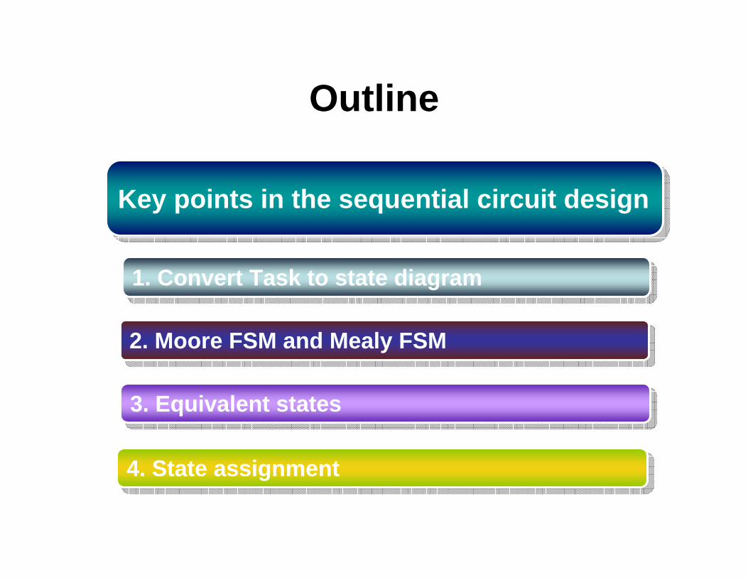
Outline
1. Convert Task to state diagram1. Convert Task to state diagram
2. Moore FSM and Mealy FSM2. Moore FSM and Mealy FSM
Key points in the sequential circuit designKey points in the sequential circuit design
3. Equivalent states3. Equivalent states
4. State assignment 4. State assignment

Example 1
• Problem– Draw a state transition diagram for a decimal
counter which counts from 0~9 and carry 1 when meeting 10(decimal)
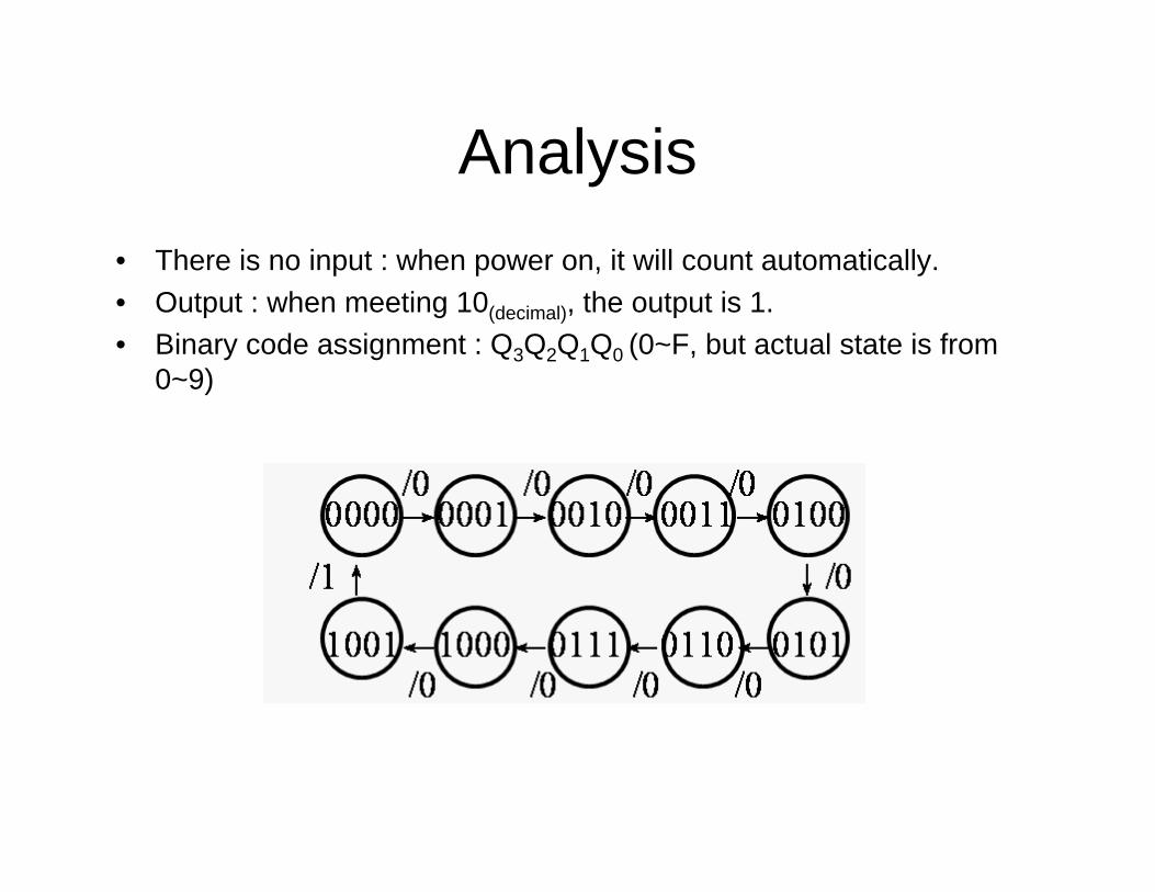
Analysis• There is no input : when power on, it will count automatically.• Output : when meeting 10(decimal), the output is 1.• Binary code assignment : Q3Q2Q1Q0 (0~F, but actual state is from
0~9)
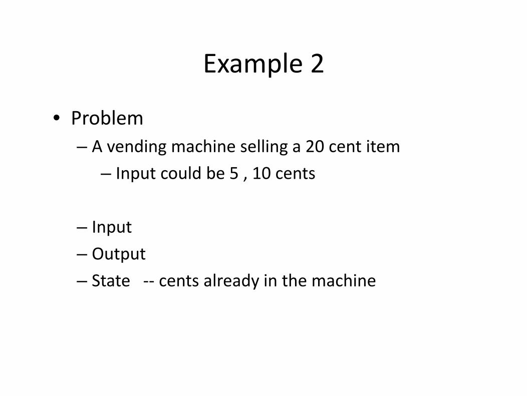
Example 2Example 2
• Problem– A vending machine selling a 20 cent itemg g
– Input could be 5 , 10 cents
– Input
– Output
– State ‐‐ cents already in the machiney
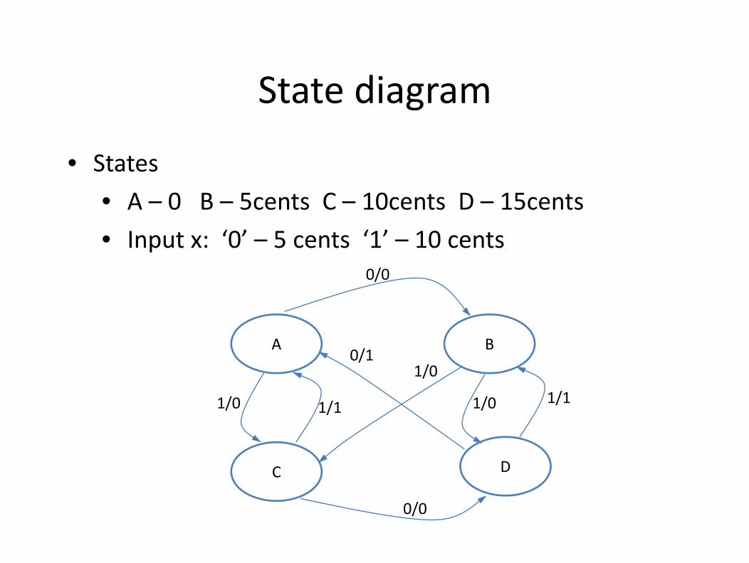
State diagramState diagram
• States
• A – 0 B – 5cents C – 10cents D – 15cents
• Input x: ‘0’ – 5 cents ‘1’ – 10 cents0/0
A B
/
A B
1/0 1/1
0/1
1/11/0
1/0
C D
/ 1/1 /
C
0/0
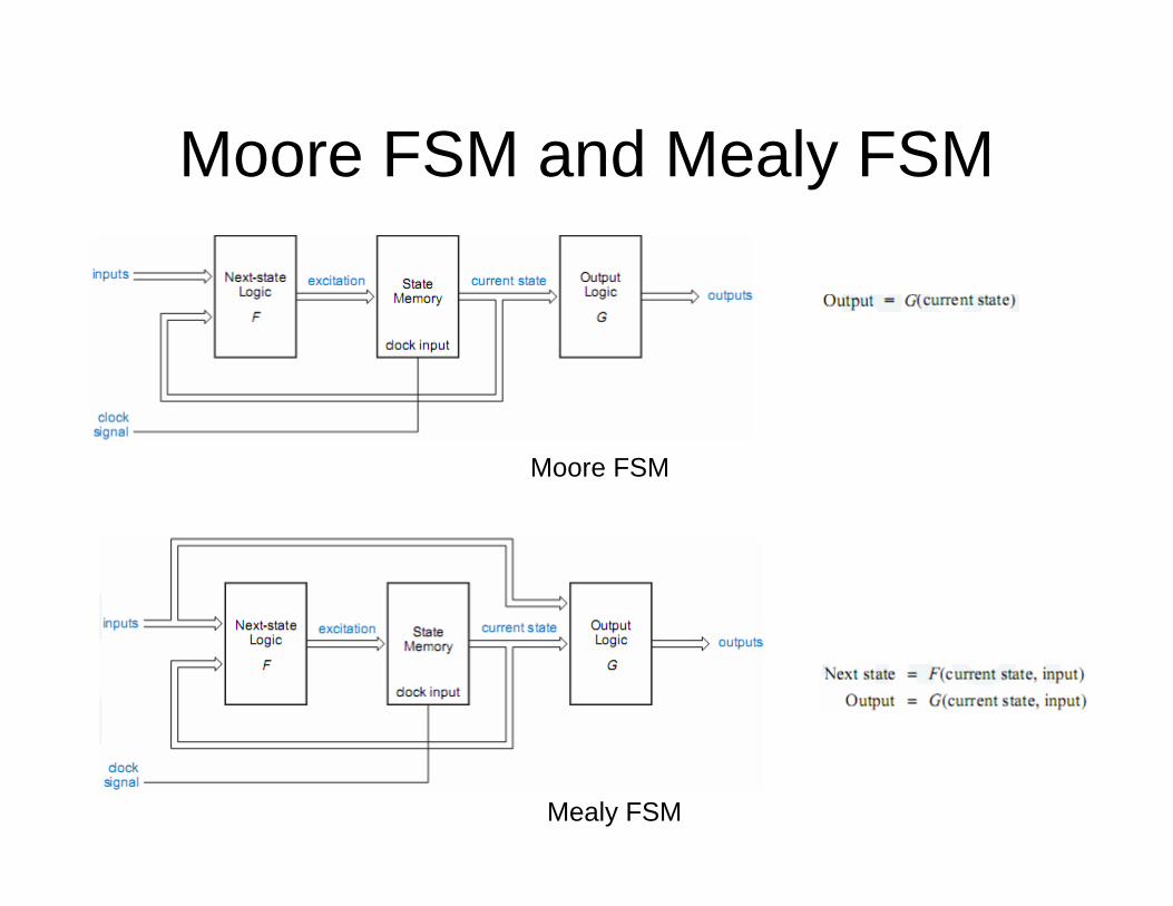
Moore FSM and Mealy FSM
Moore FSM
Mealy FSM
Example• Derive a minimal state table for a single-input and single-output
Moore-type FSM that produces an output of 1 if in the input sequence it detects either 110 or 101 patterns. Overlapping sequences should be detected. (Q3 in Quiz 2)
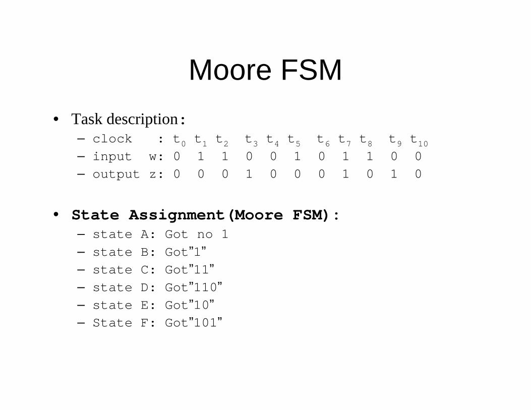
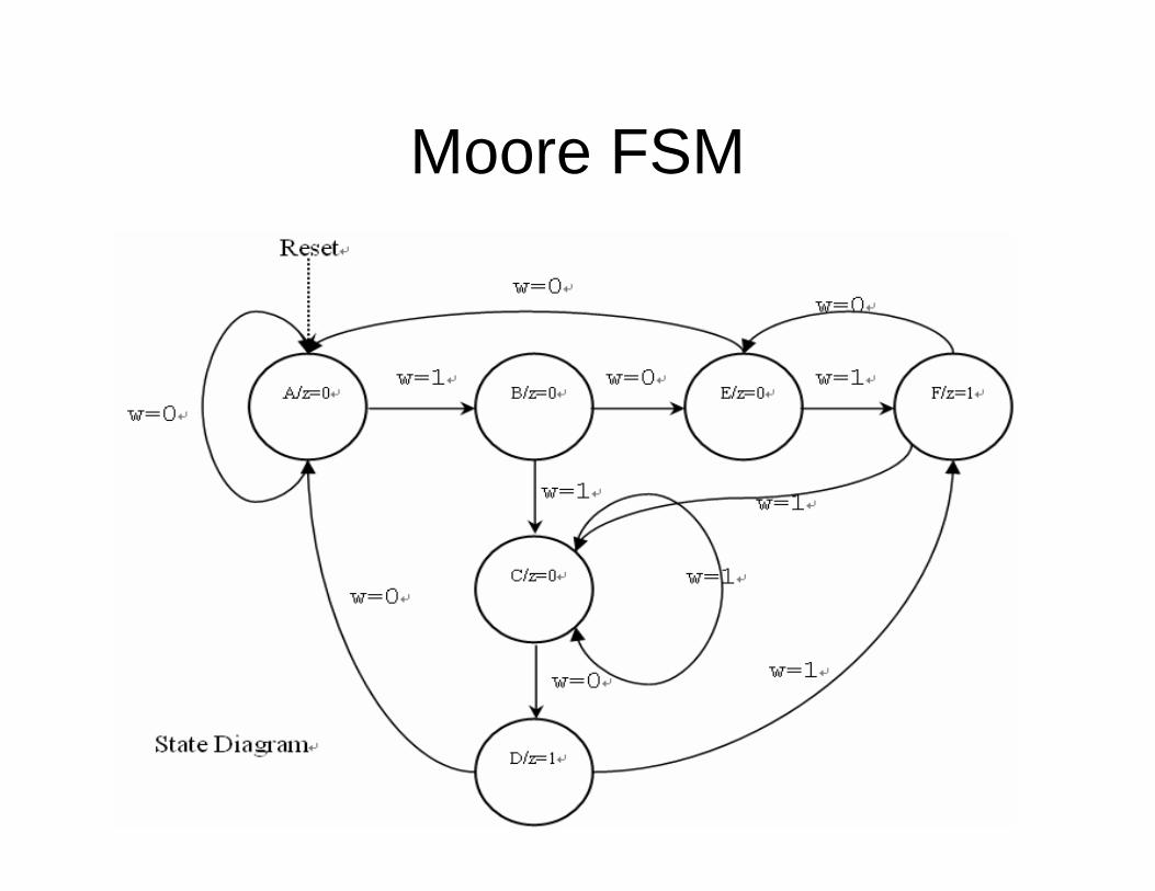
Moore FSM• Task description:
– clock : t0 t1 t2 t3 t4 t5 t6 t7 t8 t9 t10– input w: 0 1 1 0 0 1 0 1 1 0 0– output z: 0 0 0 1 0 0 0 1 0 1 0
• State Assignment(Moore FSM):– state A: Got no 1– state B: Got”1”– state C: Got”11”– state D: Got”110”– state E: Got”10”– State F: Got”101”
Moore FSM
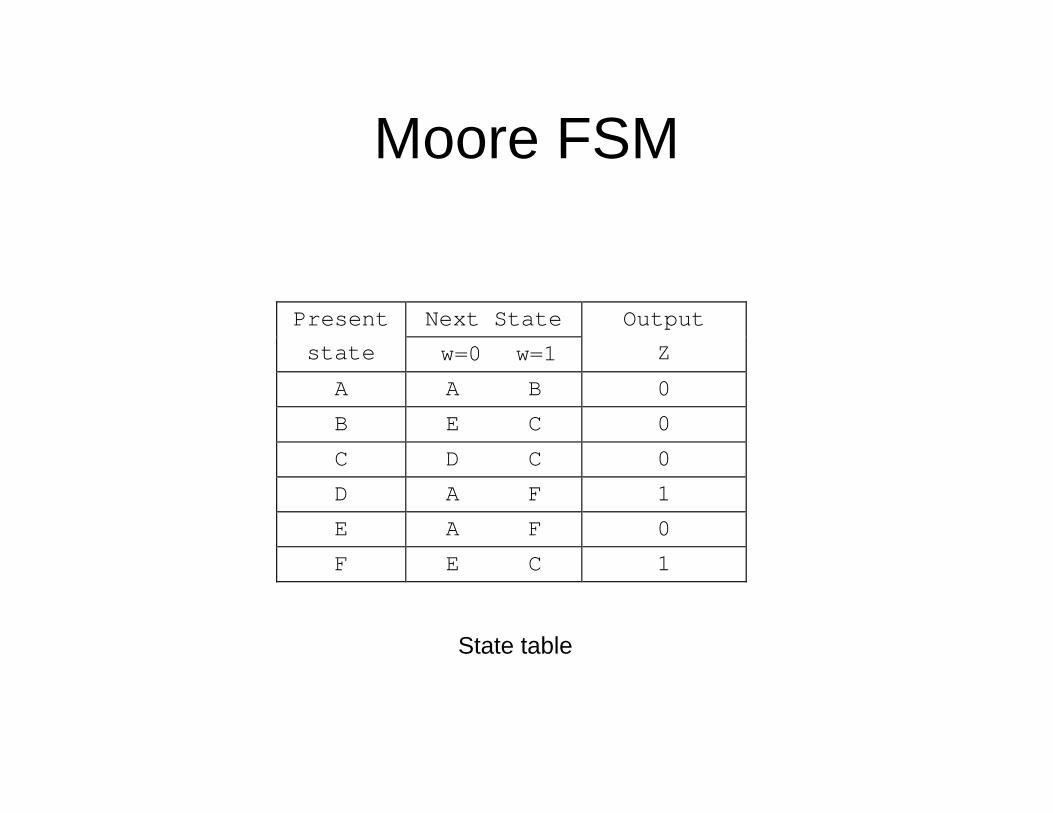
Moore FSM
Next StatePresent
state w=0 w=1
Output
Z
A A B 0
B E C 0
C D C 0
D A F 1
E A F 0
F E C 1
State table
Mealy FSM
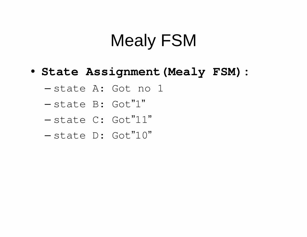
• State Assignment(Mealy FSM):– state A: Got no 1– state B: Got”1”– state C: Got”11”– state D: Got”10”
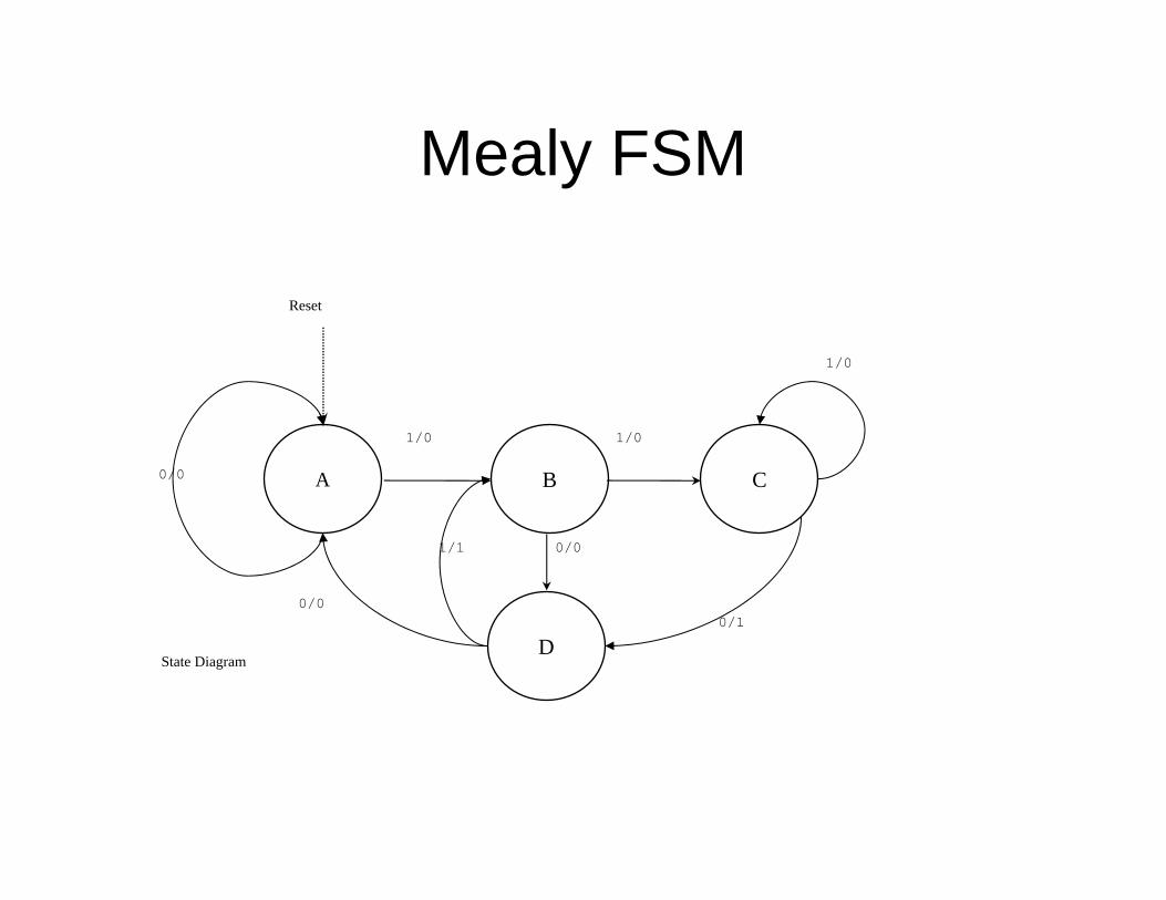
Mealy FSM
A
1/0
Reset
0/0
B
D
C
1/0
0/1
1/1
1/0
0/0
State Diagram
0/0
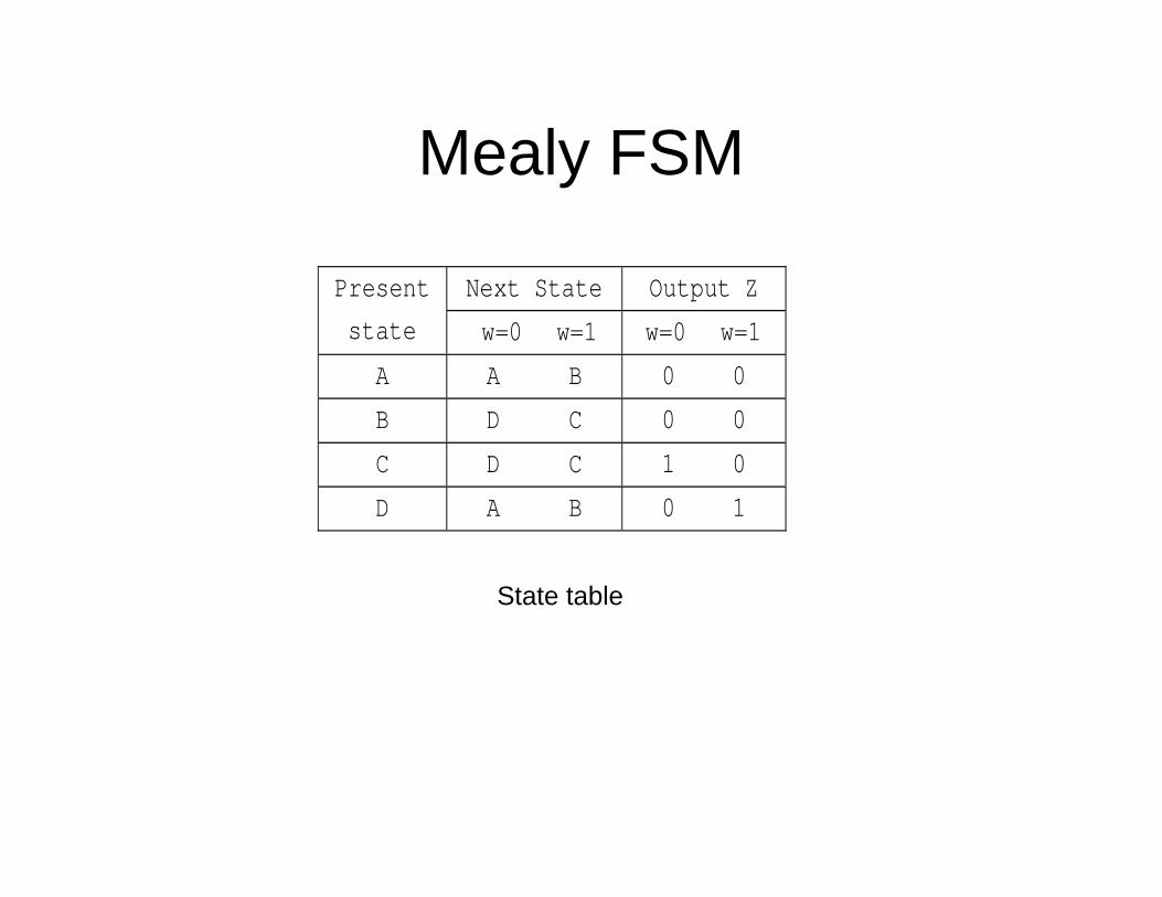
Mealy FSM
Next State Output Z Present
state w=0 w=1 w=0 w=1
A A B 0 0
B D C 0 0
C D C 1 0
D A B 0 1
State table

Equivalent Statesquivalent States– States are equivalent if:
i h hFor every input, they go to the same next state with the same output
– States are different if:For any input, they have different outputsFor any input, they have different outputs
– A decision must be deferred if:F i h h hFor every input, they have the same output, but go to different states
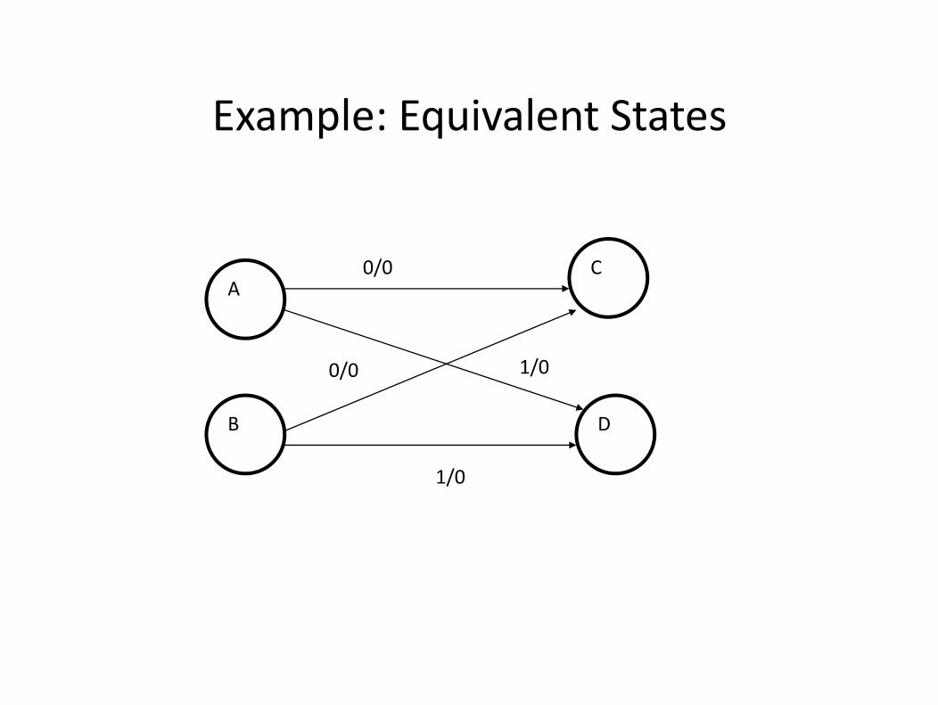
Example: Equivalent StatesExample: Equivalent States
C0/0A
C0/0
B D
0/0 1/0
1/0
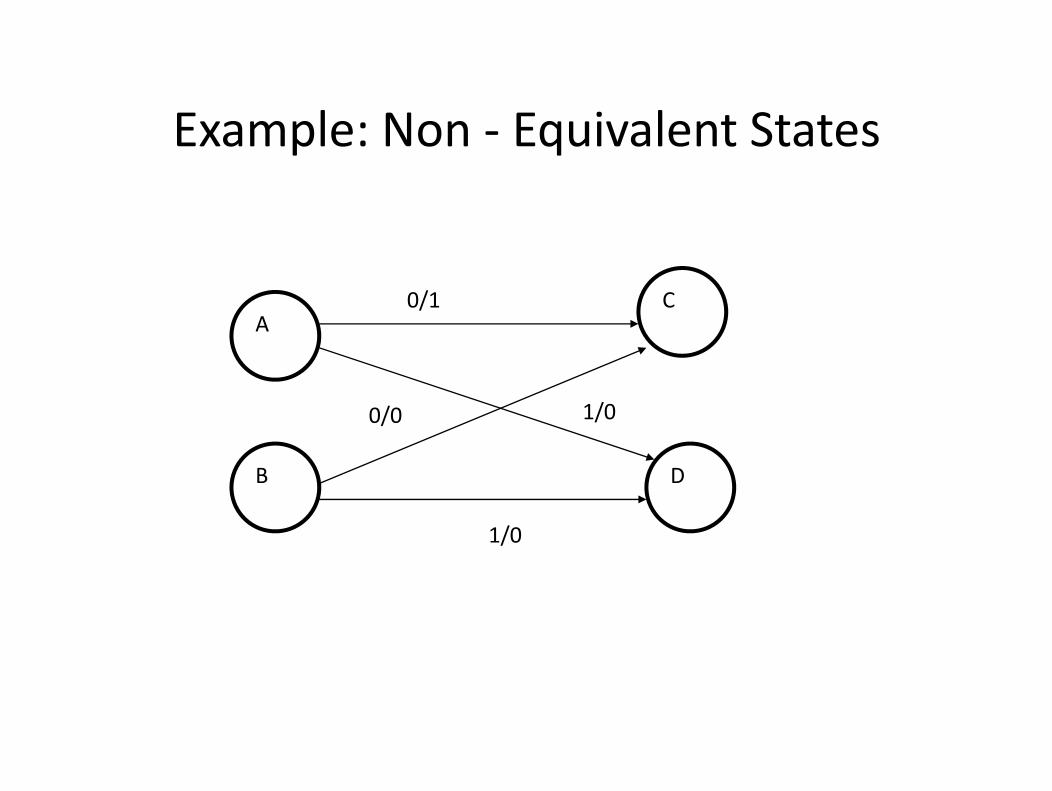
Example: Non Equivalent StatesExample: Non ‐ Equivalent States
C0/1A
C0/1
B D
0/0 1/0
1/0
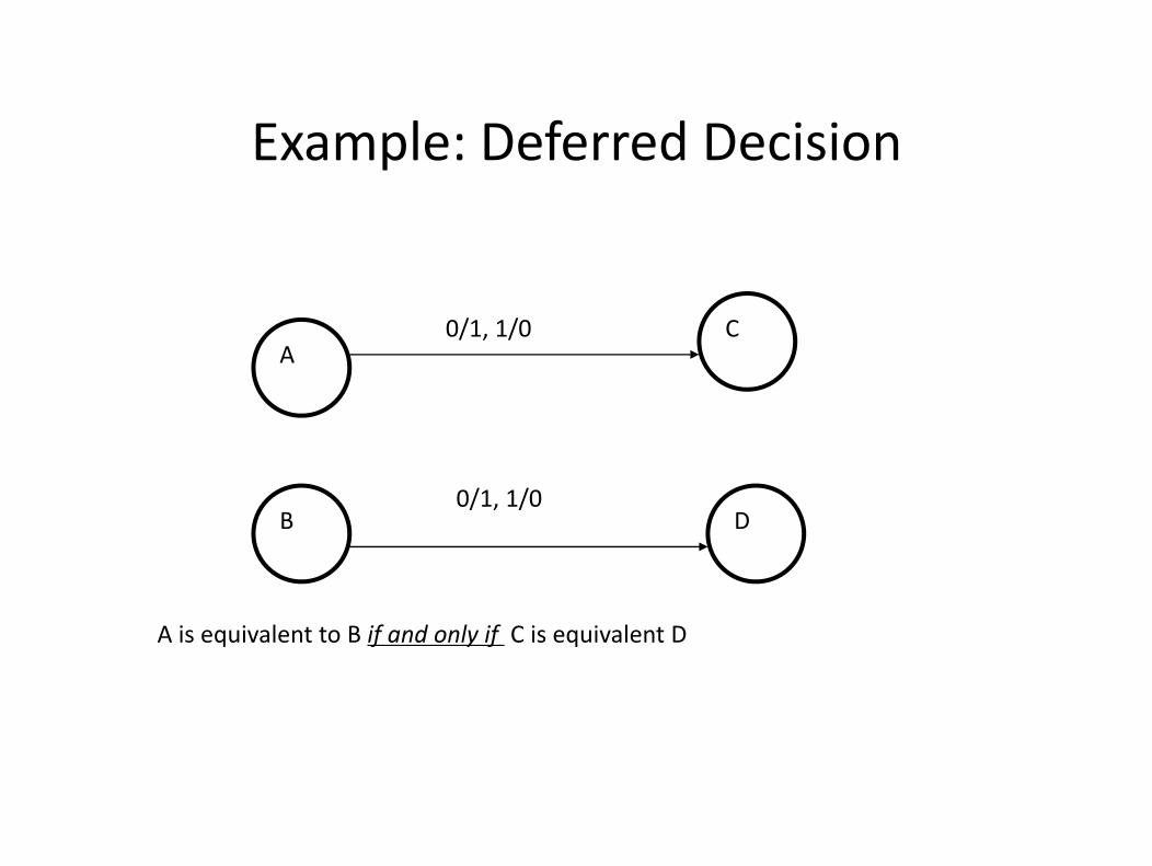
Example: Deferred DecisionExample: Deferred Decision
C0/1, 1/0A
C0/1, 1/0
B D0/1, 1/0
A i i l t t B if d l if C i i l t DA is equivalent to B if and only if C is equivalent D
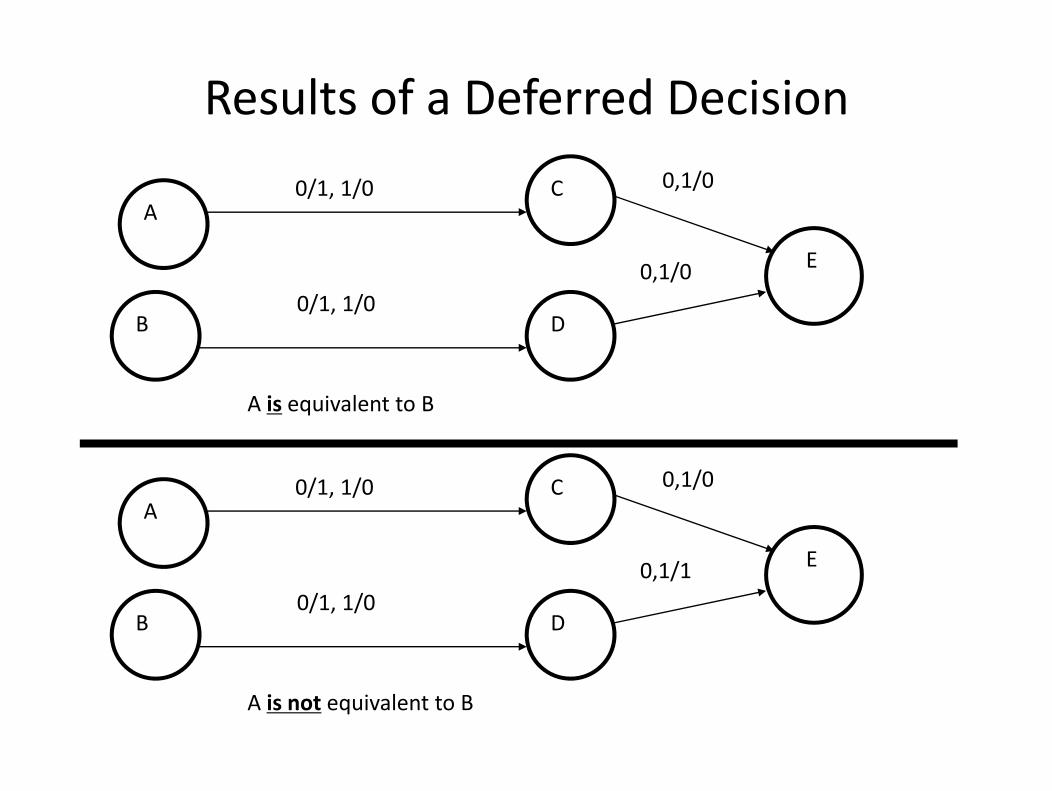
Results of a Deferred Decision
AC0/1, 1/0 0,1/0
A
0/1 1/0
E0,1/0
B D0/1, 1/0
i lA is equivalent to B
C0/1 1/0 0,1/0A
C0/1, 1/0
E
0,1/0
0 1/1
B D0/1, 1/0
0,1/1
A is not equivalent to B
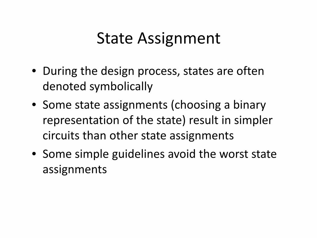
State AssignmentState Assignment
• During the design process, states are often denoted symbolicallyy y
• Some state assignments (choosing a binary representation of the state) result in simplerrepresentation of the state) result in simpler circuits than other state assignments
• Some simple guidelines avoid the worst state assignmentsassignments
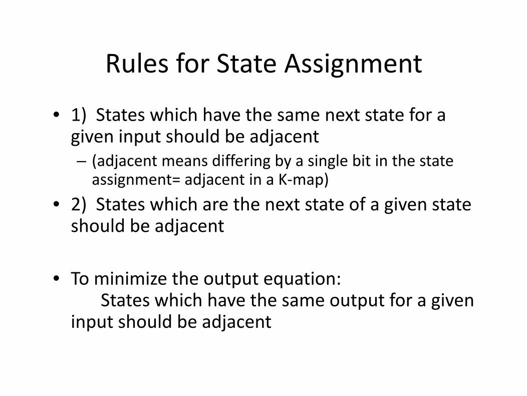
Rules for State AssignmentRules for State Assignment
1) S hi h h h f• 1) States which have the same next state for a given input should be adjacent– (adjacent means differing by a single bit in the state assignment= adjacent in a K‐map)
2) S hi h h f i• 2) States which are the next state of a given state should be adjacent
• To minimize the output equation:p qStates which have the same output for a given
input should be adjacent
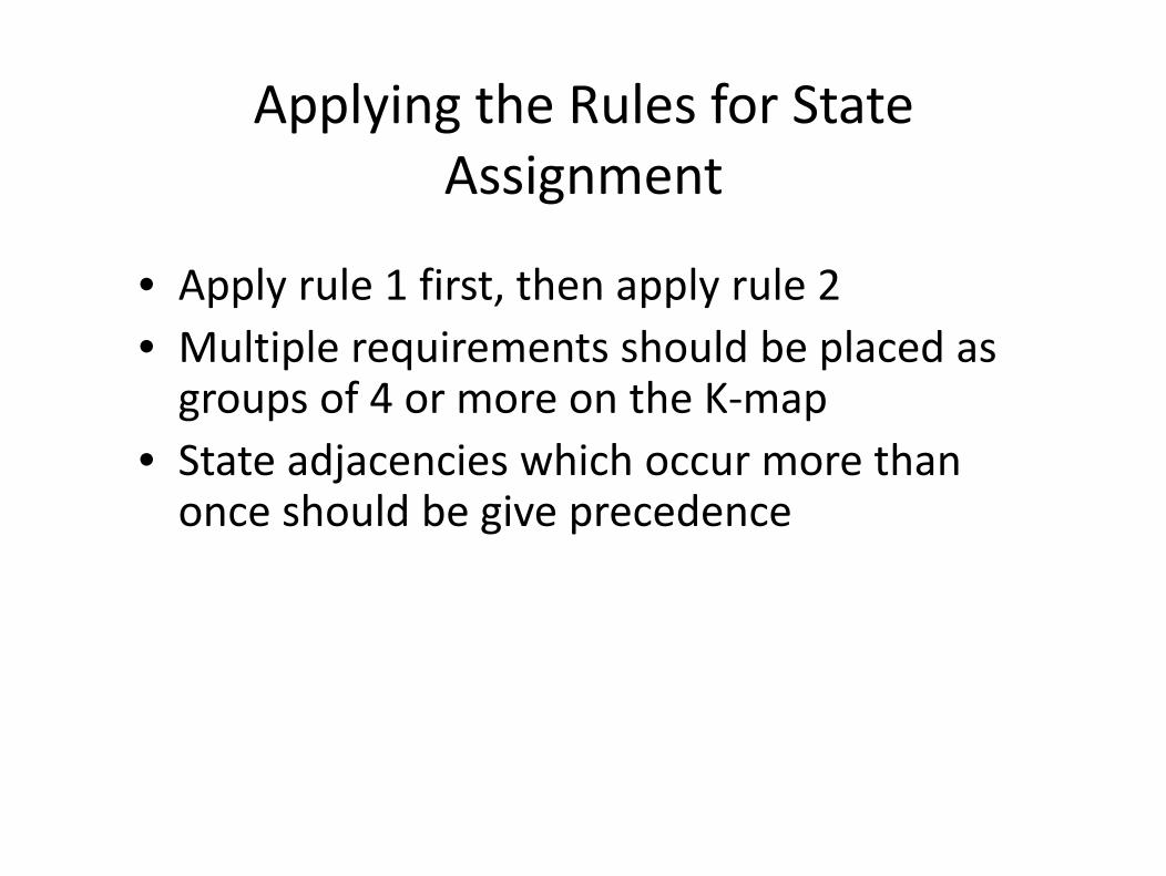
Applying the Rules for State Assignment
• Apply rule 1 first, then apply rule 2M lti l i t h ld b l d• Multiple requirements should be placed as groups of 4 or more on the K‐map
• State adjacencies which occur more than once should be give precedence
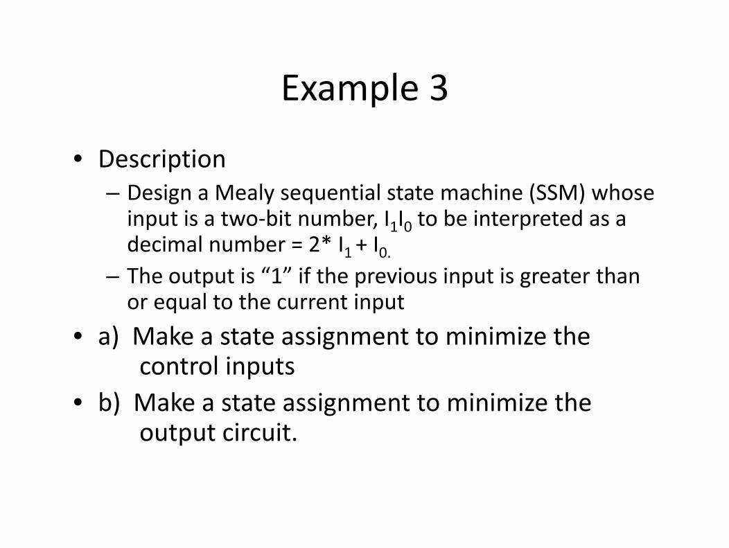
Example 3Example 3
i i• Description– Design a Mealy sequential state machine (SSM) whose i t i t bit b I I t b i t t dinput is a two‐bit number, I1I0 to be interpreted as a decimal number = 2* I1 + I0.The output is “1” if the previous input is greater than– The output is 1 if the previous input is greater than or equal to the current input
• a) Make a state assignment to minimize the• a) Make a state assignment to minimize the control inputs
• b) Make a state assignment to minimize the• b) Make a state assignment to minimize the output circuit.

Task to state diagram Mealy solutionTask to state diagram ‐Mealy solutioncurrent input/output 0/1current input/output 0/1
1/00
Lastnumberinput
1/0
3/01/1
12/0
3/00/1
13 2/0
2/0
3/0
2
2/0
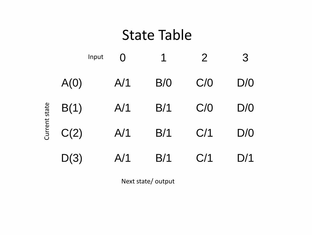
State TableState TableInput 0 1 2 3
A(0) A/1 B/0 C/0 D/0
state B(1) A/1 B/1 C/0 D/0
Curren
t
C(2) A/1 B/1 C/1 D/0
D(3) A/1 B/1 C/1 D/1
Next state/ output
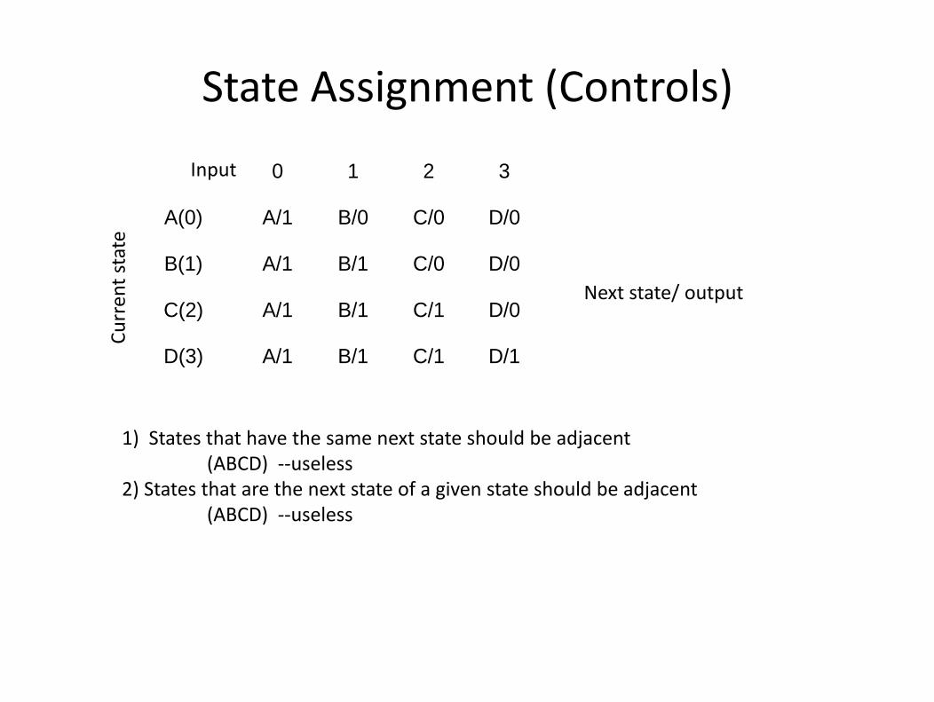
State Assignment (Controls)
0 1 2 3 Input
A(0) A/1 B/0 C/0 D/0
B(1) A/1 B/1 C/0 D/0 state
( )
C(2) A/1 B/1 C/1 D/0
D(3) A/1 B/1 C/1 D/1
Curren
t s
Next state/ output
D(3) A/1 B/1 C/1 D/1
) h h h h ld b d1) States that have the same next state should be adjacent(ABCD) ‐‐useless
2) States that are the next state of a given state should be adjacent(ABCD) l(ABCD) ‐‐useless
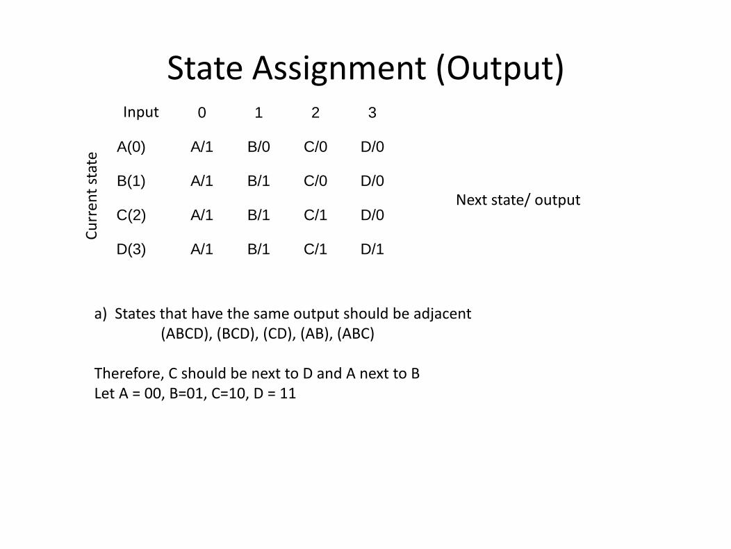
State Assignment (Output)Input 0 1 2 3
A(0) A/1 B/0 C/0 D/0
rent state
Next state/ output
A(0) A/1 B/0 C/0 D/0
B(1) A/1 B/1 C/0 D/0
C(2) A/1 B/1 C/1 D/0
Curr C(2) A/1 B/1 C/1 D/0
D(3) A/1 B/1 C/1 D/1
a) States that have the same output should be adjacent(ABCD), (BCD), (CD), (AB), (ABC)
(ABCD), (BCD), (CD), (AB), (ABC)
Therefore, C should be next to D and A next to BLet A = 00, B=01, C=10, D = 11, , ,

“Good” state assignment to
xyq1q0 Q1Q0 Z0000 00 1 assignment to
minimize output0001 00 10010 00 10011 00 1 p0011 00 10100 01 00101 01 10110 01 1 L t A 00 B 01 C 10 D 110110 01 10111 01 11000 10 01001 10 0
Z=q1q0’ + y’q1 + x’q0 + x’y’
Let A = 00, B=01, C=10, D = 11
1001 10 01010 10 11011 10 11100 11 01101 11 01110 11 01111 11 1
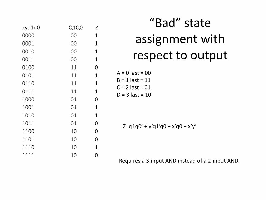
“Bad” state xyq1q0 Q1Q0 Z
assignment with respect to output
0000 00 10001 00 10010 00 1 respect to output0011 00 10100 11 00101 11 1 A = 0 last = 000 00110 11 10111 11 11000 01 0
B = 1 last = 11C = 2 last = 01D = 3 last = 10
1000 01 01001 01 11010 01 11011 01 01011 01 01100 10 01101 10 01110 10 1
Z=q1q0’ + y’q1’q0 + x’q0 + x’y’
1110 10 11111 10 0
Requires a 3‐input AND instead of a 2‐input AND.