Embed Size (px)
Citation preview
Slide 1
Department of Electrical & Computer Engineering
ELEC 691X/498X – Broadcast Signal Transmission
Fall 2015
Instructor: Dr. Reza Soleymani, Office: EV-5.125,
Telephone: 848-2424 ext.: 4103.
Office Hours: Wednesday, Thursday, 14:00 – 15:00 Time: Wednesday, 5:45 to 8:15Room: H 521
Slide 2
Department of Electrical & Computer Engineering
Lecture 1: Objective of the Course
While you learn about techniques for compression, coding,modulation in different courses, you do not receive acomprehensive view of the broadcasting. The goal of thiscourse is to provide a comprehensive view of abroadcasting system by integrating techniques fromdifferent areas: video and audio compression,communications, antenna, and RF.
A more important outcome I wish to see is: Enablingstudents to approach a problem at the system level and tobe capable of putting different pieces they have learnt invarious courses together to solve a problem.
Slide 3
Department of Electrical & Computer Engineering
Lecture 1: Contents of the Course
Digital Transmission Standards (ATSC, DVB-T/T2, DVB-S/S2). Video Compression Techniques: MPEG-2, H.264, HEVC, J2K. Performance measures for Digital TV: Noise, Error, Impairments. Packet Structure: Tables (PAT, PMT). Multiplexing and De-multiplexing. Channel Coding and Modulation for Digital Television. Cyclic codes Digital TV Transmitters: Up/converters, Power Amplifiers, Combiners,
Equalizers and pre-correctors. Transmission Lines: Cables, Wave Guides, link budget calculation. Transmitting Antennas for Digital Broadcasting. Advanced Topics: COFDM, LDPC Codes. Satellite Broadcasting. IPTV and Multi-platform formats.
Slide 4
Department of Electrical & Computer Engineering
Lecture 1:Grading Scheme
Graduate: Assignment: 5% Project: 20% Midterm : 25% Final Examination: 50%
Undergraduate: Assignment: 10% Midterm : 30% Final Examination: 60%
Note 1: Undergraduate students may opt to follow the graduate scheme.Note 2: Failing to write a Midterm results in losing the 30% assigned to the test. Note 3: In order to pass the course, you should get at least 60% in the final.
Slide 5
Department of Electrical & Computer Engineering
Lecture 1:Course Material
Textbook: Ioannis Pitas, Digital video and television – April 16, 2013
References:
• A/300:2017, “ATSC 3.0 System”, https://www.atsc.org/atsc20-standard/a3002017-atsc-3-0-system/
• ETSI EN 300 744 V1.6.1 (2009-01) Digital Video Broadcasting (DVB); Framing structure, channel coding and modulation for digital terrestrial television. Available at:http://www.etsi.org/deliver/etsi_en/300700_300799/300744/01.06. 01_60/en_300744v010601p.pdf
• ETSI EN 302 307 V1.2.1 (2009-08) Digital Video Broadcasting (DVB); Second generation framing structure, channel coding and modulation systems for Broadcasting. Available at:
Slide 6
Department of Electrical & Computer Engineering
Lecture 1:Course Material
References (Continued): http://www.etsi.org/deliver/etsi_en/302300_302399/302307/01.02.
01_60/en_302307v010201p.pdf Interactive Services, News Gathering and other broadband satellite
applications (DVB-S2). Available at:www.etsi.org/deliver/etsi_en/302300.../en_302307v010102p.pdf
H264 (05/2003) Advanced video coding for generic audiovisualservices, Telecommunication Standardization Section of ITU. Availableat: https://www.itu.int/rec/T-REC-H.264
Gerald W. Collins, Fundamentals of Digital Television Transmission,John Wiley and Sons, 2001.
IEEE Transactions on Broadcasting: free for Concordia students at:http://ieeexplore.ieee.org/xpl/RecentIssue.jsp?punumber=11.
Course Notes.
Slide 7
Department of Electrical & Computer Engineering
Lecture 1:About the Course Material
Why so many references? Most of the books written on the subject target practicing engineers
and not the students. They cover either only a few topics or manytopics with not enough depth.
The area while mature is still evolving. So, it is good to learn to get tothe source of things (Standards).
Why this text? It is well written and covers most of the topics in reasonable detail. It is very inexpensive: You may buy it online, e.g., from abebooks.com
for $20 US. ( around $30.00 Canadian with shipping).
Slide 8
Department of Electrical & Computer Engineering
Lecture 1:What will be covered in this lecture
In addition to the introduction given so far, in this lecture, we will cover: The basic components of a broadcast system. Overview of Analog TV. Overview of Digital TV. Advantages of the Digital TV over Analog TV.
Slide 9
Department of Electrical & Computer Engineering
Lecture 1:Components of a TV system
At the highest level, a television system consists of two entities:• Service provider: A TV station, a cable company, a satellite service
provider, etc. You may include Internet based media streaming)services such as Youtube and NETFLIX.
• A client (an end user): You and I sitting at home watching TV orsome video on the Internet.
Let’s start with the receiver side (end user), not because it is more important but because it is simpler. • The first thing you need is a device to see video and listen to the sound,
that is, a TV, a computer monitor a tablet, a smart phone.• Next you need some connection to the outside world, i.e., some way to
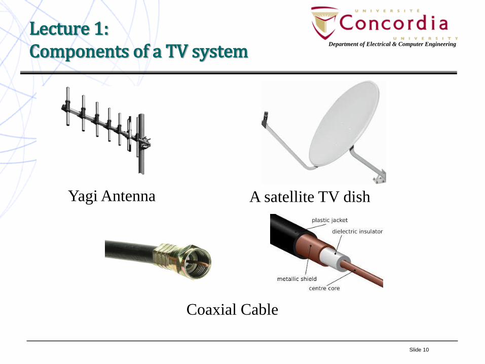
get the Video signal into your house. This can be a Yagi antenna in caseof terrestrial TV, a Dish antenna in case of satellite TV, a coaxial cablein case of Cable TV, some sort of Internet connection in case of IPTV.
Slide 10
Department of Electrical & Computer Engineering
Lecture 1:Components of a TV system
Yagi Antenna A satellite TV dish
Coaxial Cable
Slide 11
Department of Electrical & Computer Engineering
Lecture 1:Components of a TV system
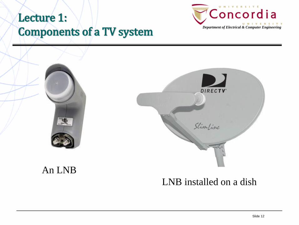
• An antenna, a cable or a wire bring Radio Frequency (RF) signal toyour house and your TV or monitor only understand levels specifyingthe colour and luminance of the image pixels. Hence, you needsomething to transform the RF content of the cable, wire or antenna tovideo (and audio) signal. First you need to translate waveform fromRF to IF (Intermediate Frequency) easy for your electroniccomponents to handle. This is called a down converter (D/C). Forexample, a satellite TV signal working at Ku-band has a centerfrequency in the 12 GHz* range. A down converter can bring it to theIF range of 0.95 to 2.15 GHz. You need then to amplify this beforeputting it again into a cable. This is done using an LNA (Low NoiseAmplifier). In the case of satellite TV, the down converter and LNA areintegrated into a device called Low Noise Block (LNB).
* GHz stands for a billion Hz.
Slide 12
Department of Electrical & Computer Engineering
Lecture 1:Components of a TV system
An LNB
LNB installed on a dish
Slide 13
Department of Electrical & Computer Engineering
Lecture 1:Components of a TV system
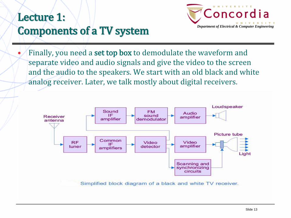
• Finally, you need a set top box to demodulate the waveform andseparate video and audio signals and give the video to the screenand the audio to the speakers. We start with an old black and whiteanalog receiver. Later, we talk mostly about digital receivers.
Slide 14
Department of Electrical & Computer Engineering
Lecture 1:Components of a TV system
• In the case of digital set top boxes, we have all the components you learn inELEC6831: Digital Transmission I. These include:
– Analog to Digital Converter,
– Matched filter,
– Decoder (if applicable),
– Demodulator.
• New TV sets have the receiver for terrestrial TV, so you do not need anexternal set top box. Some models of TV (so called, Smart TV) also haveEthernet input as well as WiFi.
• For satellite TV still you need a set top box. However, it is due to economic(small market size) of satellite TV rather than technical reasons.
• For cable TV you need set top box (DVR)mainly for recoding and auxiliaryfunctions such as forward/backward, picture in picture, etc. Otherwise giventhe volume, the receiver can be economically integrated in the TV
Slide 15
Department of Electrical & Computer Engineering
Lecture 1:Components of a TV system
Components of the transmitting side:We started by discussing the equipment at the receiver (viewer) side not because it is more important, but because it is simpler and we deal with more familiar devices: things that we deal with in our daily lives such as a TV, and antenna, cable or telephone wire, DVR, etc. Now, we use our knowledge of what we use at home to list the entities (hardware and software) that a service provider such as a television station, a cable company or a satellite TV company needs to have in order to be able to send the signal to our homes.
Most of you have some communications background. In particular, many of you have taken digital communications course or possibly are taking it concurrently with this course. So, you are familiar with the fact that any device you have at the transmitter side has a counterpart at the receiver side, i.e., an entity that undoes what the transmitter side entity has done. For example, you have a modulator at the transmitting station and need a demodulator at the receiver side to translate back the modulated information to the its original form, maybe with some error. Similarly, an encoder at the transmitter requires a decoder at the receiver.
Slide 16
Department of Electrical & Computer Engineering
Lecture 1:Components of a TV system
The terms like MODEM (modulator plus demodulator) or CODEC (a coder and a decoder) have been tossed to emphasize this fact. It is important to note that, in a communication system we have modem or codec because the communications process is bi-directional (or in technical terms, full-duplex), i.e., each node is both the transmitter and the receiver. However, a TV system is almost always one way, i.e., there is no signal going from our TV to the TV station or cable company. Theremight be a minor level of interactivity in new systems, but they are usually atmuch lower data rate and are for request and signaling. So, the good news is thatmost of the things you have learnt in your digital communications course can helpyou in grasping the subjects discussed in this course. On the other hand if youhave not taken any communications course, what you learn in this course willprepare you for such course.
Now, let’s see what we need to have in order to broadcast a TV program. In order not to be very abstract, let’s focus on regular (terrestrial) TV station.
The first thing a TV station needs is a way to generate the content (of course some of the content such as movies are generated by a third party). In order to create content, a TV station needs rooms furnished according to their functionality.
Slide 17
Department of Electrical & Computer Engineering
Lecture 1:Video Signal
For example, a News room for broadcasting news another for interviews. Each of these will be called a studio. In addition to the furniture, a studio needs lighting, cameras, mixers, etc. In this course, we will not be concerned with the studio and studio equipment. Our job starts at the output of the studio, that is, with a cable providing us with video and accompanying audio and possibly data signals. The most important part of the signal coming out of the studio, and the one taking most our transmission bandwidth is video signal. Let’s digress from the station equipment and see what the video signal is.
A video signal is a sequence of still pictures. In order for us to feel the movement there should be a certain number of still pictures per unit of time. Human visual system can process 10 to 12 images per second. So in order to perceive any motion at all, we need the number of still images (called frames) to exceed ten. Of course such low numbers does not result in natural looking video. The number of frames per second (frame rate) for the movies was established as 24 frames per second. For the TV the frame rates are 30 in North America and Japan, and 25 in most other places. Higher rate (60 and 120) have been added in more recent versions of the standard.
Slide 18
Department of Electrical & Computer Engineering
Lecture 1:Video Signal
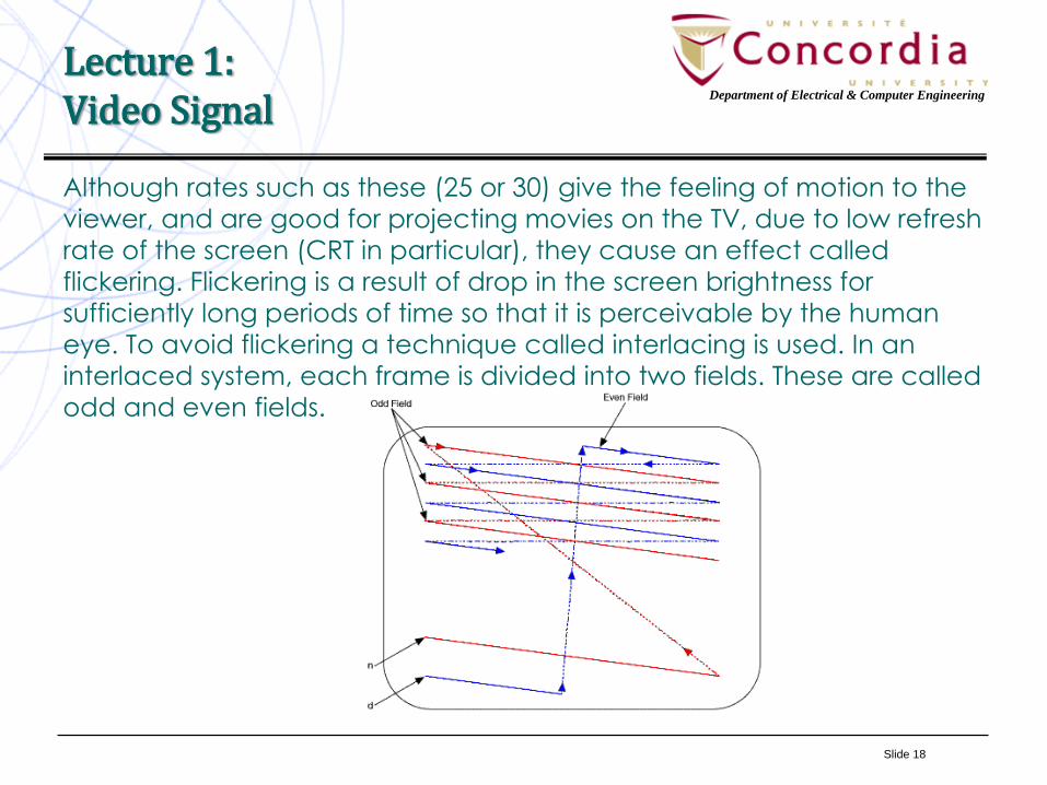
Although rates such as these (25 or 30) give the feeling of motion to the
viewer, and are good for projecting movies on the TV, due to low refresh
rate of the screen (CRT in particular), they cause an effect called
flickering. Flickering is a result of drop in the screen brightness for
sufficiently long periods of time so that it is perceivable by the human
eye. To avoid flickering a technique called interlacing is used. In an
interlaced system, each frame is divided into two fields. These are called
odd and even fields.
Slide 19
Department of Electrical & Computer Engineering
Lecture 1:
Video Signal
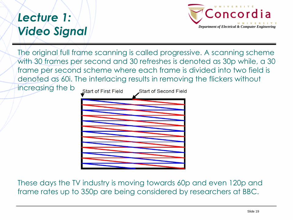
The original full frame scanning is called progressive. A scanning scheme
with 30 frames per second and 30 refreshes is denoted as 30p while, a 30
frame per second scheme where each frame is divided into two field is
denoted as 60i. The interlacing results in removing the flickers without
increasing the bandwidth.
These days the TV industry is moving towards 60p and even 120p and
frame rates up to 350p are being considered by researchers at BBC.
Slide 20
Department of Electrical & Computer Engineering
Lecture 1:
Video Signal
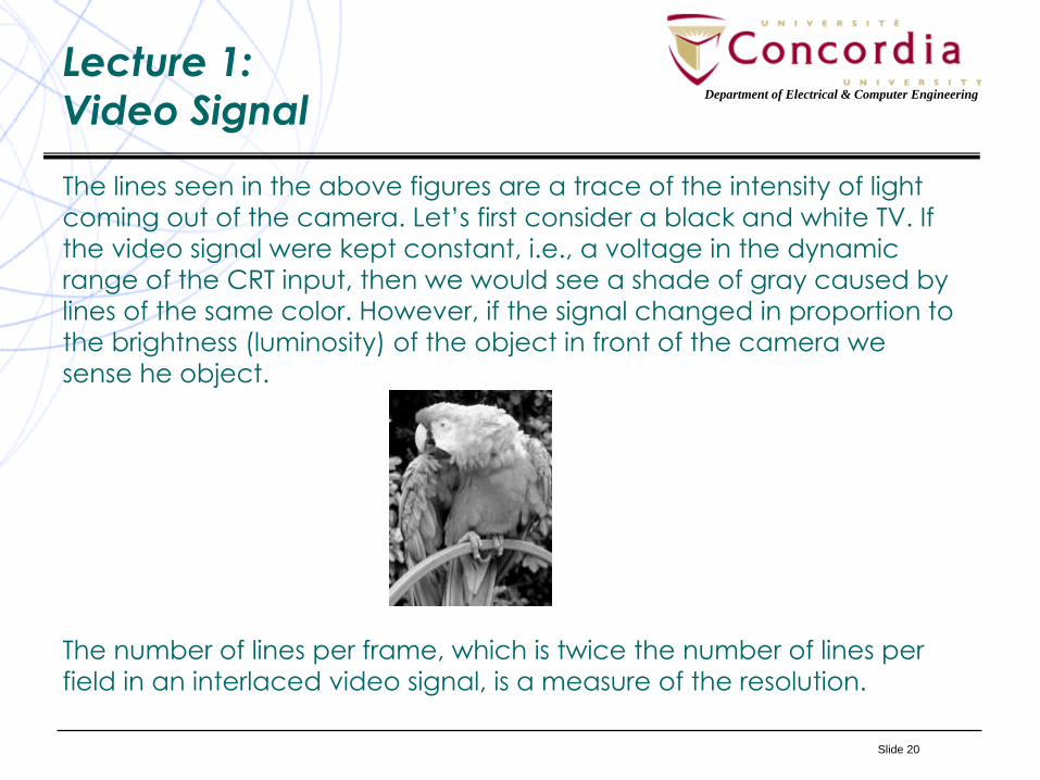
The lines seen in the above figures are a trace of the intensity of light
coming out of the camera. Let’s first consider a black and white TV. If
the video signal were kept constant, i.e., a voltage in the dynamic
range of the CRT input, then we would see a shade of gray caused by
lines of the same color. However, if the signal changed in proportion to
the brightness (luminosity) of the object in front of the camera we sense he object.
The number of lines per frame, which is twice the number of lines per
field in an interlaced video signal, is a measure of the resolution.
Slide 21
Department of Electrical & Computer Engineering
Lecture 1:
Video Signal
The number of lines per frame for analog TV were 525 in North
America (NTSC standard) and 625 in the European standards
(PAL and SECAM).
In addition to luminosity, a video signal contains audio and
signaling information. The latter refers to control information
specifying the beginning of a field and end of a trace.
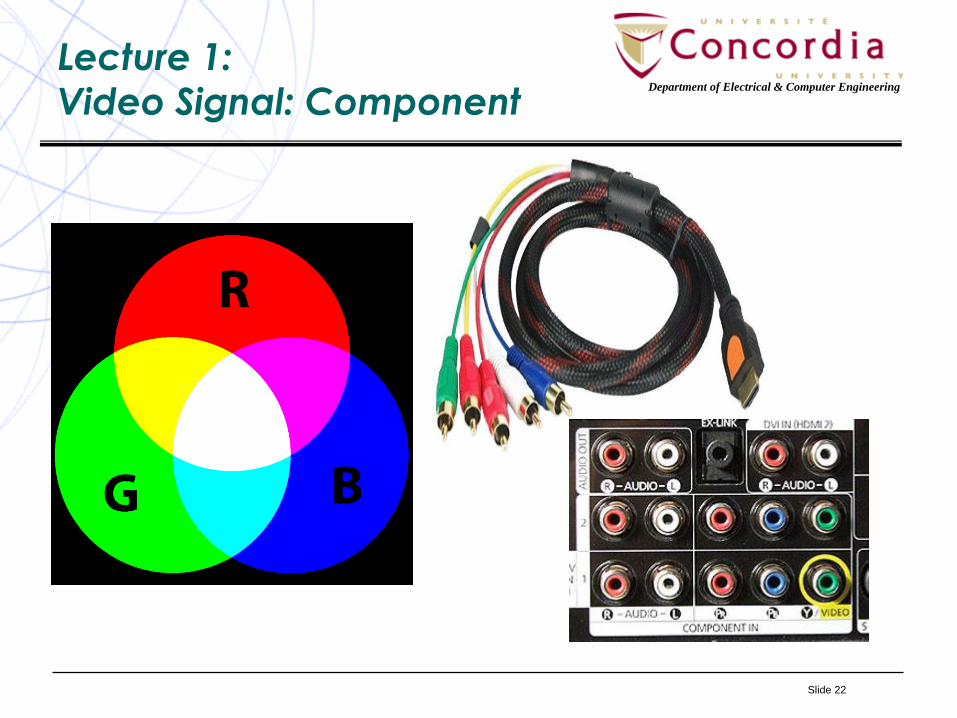
Now let’s move to colour TV (We are still talking about analog
TV). In addition to luminosity, we need the video signal to convey
the colour. From high school physics you know that all colours
can be generated by proper mix of three distinct colours. In TV
and computer industry, the three basic colours used are Red (R),
Green (G) and Blue (B) thus the notation RGB. The RGB
(component) interface has five cables: 3 four colours Red, Green
and Blue and 2 for audio (stereo). The picture in next page shows
and RGB to HDMI converter.
Slide 22
Department of Electrical & Computer Engineering
Lecture 1:
Video Signal: Component
Slide 23
Department of Electrical & Computer Engineering
Lecture 1:
Video Signal: Composite
While it is not a big deal running five wires between two devices
close to one another such as a camera and a monitor, recorder
or encoder (except for some inconvenience), it is not a good
idea to have five separate lines when it comes to transmission. It
is best if we could combine all these five signals into one and
convey it with one cable to the RF section for modulation and
transmission. This was the reason for introducing composite video.
Before talking about composite video, let’s mention that, we do
not need necessarily to send the three colours Red, Green and
Blue. Any linear combination of these three colours can be
transmitted and the receiver can recover the three colours. It is
just solving a system of three linear equations with three unknowns. The tree signals sent are 𝑘𝑟𝑅 + 𝐾𝑔𝐺 + 𝐾𝑏𝐵 𝐶𝑏 = 𝑌 −
𝐵 and 𝐶𝑟 = 𝑌 − 𝑅. The signal Y is the luminosity (called luma) and
makes the colour TV backward compatible with black and white
TV.
C
Slide 24
Department of Electrical & Computer Engineering
Lecture 1:
Video Signal: Composite
𝐶𝑏 and 𝐶𝑟 convey the colour information thus called chroma. The above
scheme denoted by 𝑌𝐶𝑏𝐶𝑟 was suggested by CCITT* predecessor to ITU-
T** and ITU-R***). The TV standards in North America and Europe used
YIQ (NTSC in North America and Japan) and YUV (PAL and SECAM in
Europe and most other parts of the world). In order to recover R, G and B from YCbCr one has to know 𝑘𝑟, 𝑘𝑔 and 𝑘𝑏. There are several values
used based on the standard as well as the application. The one
suggested by ITU-R called BT.601 is 𝑌 = 𝑘𝑟𝑅 + (1 − 𝑘𝑟 − 𝑘𝑏)𝐺 + 𝑘𝑏𝐵, 𝐶𝑏 =1
2.
𝐵−𝑌
1−𝑘𝑏and 𝐶𝑟 =
1
2.
𝑅−𝑌
1−𝑘𝑟with 𝑘𝑏 = 0.114 and 𝑘𝑟 = 0.299.
The three video signals generated according to the above scheme are
frequency multiplexed forming a single signal called the composite
signal.
• * Comité Consultatif International Téléphonique et Télégraphique.
• ** International Telecommunications Union – Telecommunications Sector.
• *** International Telecommunications Union – Radiocommunications Sector.
Slide 25
Department of Electrical & Computer Engineering
Lecture 1:
Video Signal: Composite
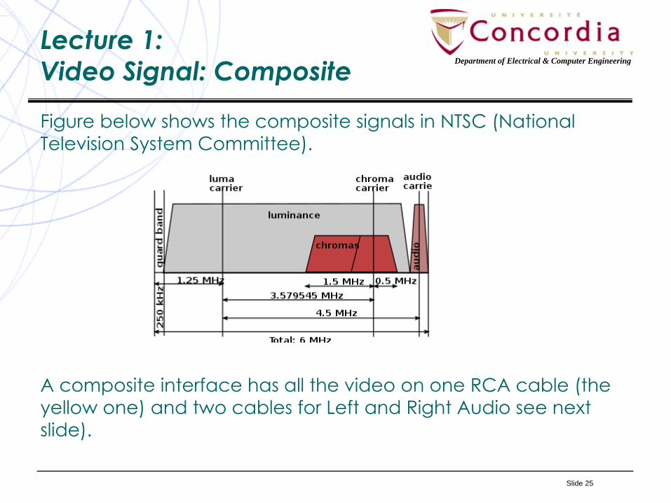
Figure below shows the composite signals in NTSC (National
Television System Committee).
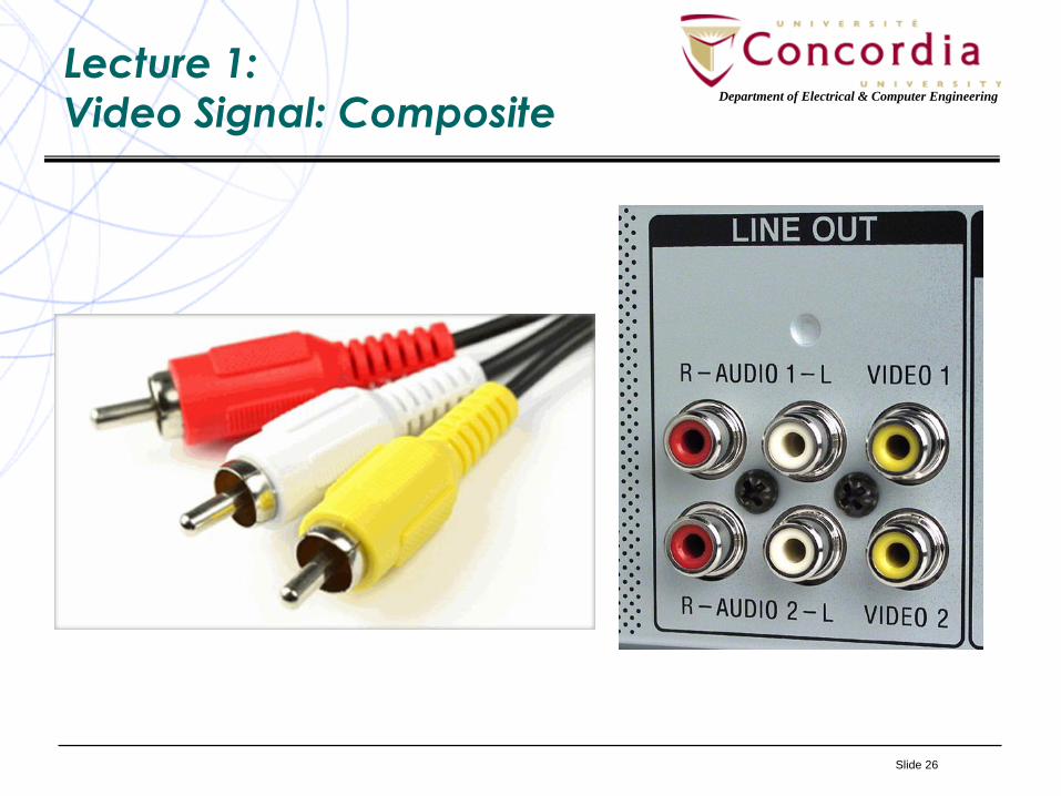
A composite interface has all the video on one RCA cable (the
yellow one) and two cables for Left and Right Audio see next
slide).
Slide 26
Department of Electrical & Computer Engineering
Lecture 1:
Video Signal: Composite
Slide 27
Department of Electrical & Computer Engineering
Lecture 1:
Video Signal: S-Video
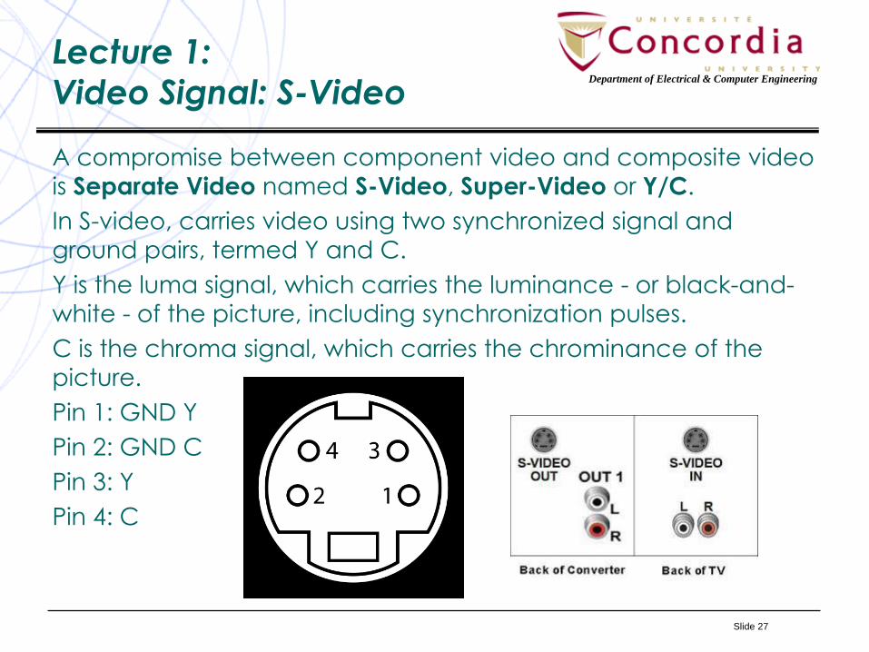
A compromise between component video and composite video
is Separate Video named S-Video, Super-Video or Y/C.
In S-video, carries video using two synchronized signal and
ground pairs, termed Y and C.
Y is the luma signal, which carries the luminance - or black-and-
white - of the picture, including synchronization pulses.
C is the chroma signal, which carries the chrominance of the
picture.
Pin 1: GND Y
Pin 2: GND C
Pin 3: Y
Pin 4: C
Slide 28
Department of Electrical & Computer Engineering
Lecture 1:
Digital Television standards
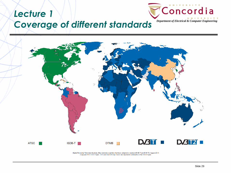
There are mainly four Digital TV (DTV)standards:
• DVB: Digital Video Broadcasting.
• ATSC: Advanced Television Systems Committee.
• DTMB: Digital Terrestrial Multimedia Broadcast used
in People's Republic of China, Hong Kong, and
Macau.
• ISDV: Integrated Services Digital Broadcasting used
in Japan and most of South America.
Slide 29
Department of Electrical & Computer Engineering
Lecture 1
Coverage of different standards
Slide 30
Department of Electrical & Computer Engineering
Lecture 1:
Digital Television: DVB
• DVB is a suite of internationally accepted standards
developed under DVB project which is an industry alliance
with over 200 members formed in 1993 (www.dvb.org). The first
versions of DVB were released in 1997 and was published by a
Joint Technical Committee (JTC) of the European
Telecommunications Standards Institute (ETSI), European
Committee for Electrotechnical Standardization (CENELEC)
and European Broadcasting Union (EBU).
• DVB has standards for different media such as:
– DVB-T/T2 for terrestrial.
– DVB-S/S2/S2X for satellite.
– DVB-C/C2 for cable.
– DVB-H for Handheld devices (mobile).
– DVB-IPTV for streaming content over IP.
Slide 31
Department of Electrical & Computer Engineering
Lecture 1
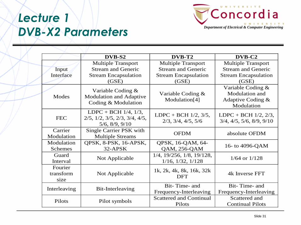
DVB-X2 Parameters
DVB-S2 DVB-T2 DVB-C2
Input
Interface
Multiple Transport
Stream and Generic
Stream Encapsulation
(GSE)
Multiple Transport
Stream and Generic
Stream Encapsulation
(GSE)
Multiple Transport
Stream and Generic
Stream Encapsulation
(GSE)
Modes
Variable Coding &
Modulation and Adaptive
Coding & Modulation
Variable Coding &
Modulation[4]
Variable Coding &
Modulation and
Adaptive Coding &
Modulation
FEC
LDPC + BCH 1/4, 1/3,
2/5, 1/2, 3/5, 2/3, 3/4, 4/5,
5/6, 8/9, 9/10
LDPC + BCH 1/2, 3/5,
2/3, 3/4, 4/5, 5/6
LDPC + BCH 1/2, 2/3,
3/4, 4/5, 5/6, 8/9, 9/10
Carrier
Modulation
Single Carrier PSK with
Multiple Streams OFDM absolute OFDM
Modulation
Schemes
QPSK, 8-PSK, 16-APSK,
32-APSK
QPSK, 16-QAM, 64-
QAM, 256-QAM 16- to 4096-QAM
Guard
Interval Not Applicable
1/4, 19/256, 1/8, 19/128,
1/16, 1/32, 1/128 1/64 or 1/128
Fourier
transform
size
Not Applicable 1k, 2k, 4k, 8k, 16k, 32k
DFT 4k Inverse FFT
Interleaving Bit-Interleaving Bit- Time- and
Frequency-Interleaving
Bit- Time- and
Frequency-Interleaving
Pilots Pilot symbols Scattered and Continual
Pilots
Scattered and
Continual Pilots
Slide 32
Department of Electrical & Computer Engineering
Lecture 1:
Digital Television: ATSC
ATSC standard has been developed by the Advanced Television
Systems Committee, Inc., which is an international, non-profit
organization developing voluntary standards for digital television.
ATSC was formed in 1982 by the member organizations of the
Joint Committee on InterSociety Coordination (JCIC): the
Electronic Industries Association (EIA), the Institute of Electrical
and Electronic Engineers (IEEE), the National Association of
Broadcasters (NAB), the National Cable Telecommunications
Association (NCTA), and the Society of Motion Picture and
Television Engineers (SMPTE). ATSC members represent the
broadcast, broadcast equipment, motion picture, consumer
electronics, computer, cable, satellite, and semiconductor
industries.
ATSC standard is used in Canada, Dominican Republic, El
Salvador, Guatemala, Honduras, Mexico, and South Korea.

Slide 33
Department of Electrical & Computer Engineering
Lecture 1:
Digital Television: ATSC
ATSC standard has been developed by the Advanced Television
Systems Committee, Inc., which is an international, non-profit
organization developing voluntary standards for digital television.
ATSC was formed in 1982 by the member organizations of the
Joint Committee on InterSociety Coordination (JCIC): the
Electronic Industries Association (EIA), the Institute of Electrical
and Electronic Engineers (IEEE), the National Association of
Broadcasters (NAB), the National Cable Telecommunications
Association (NCTA), and the Society of Motion Picture and
Television Engineers (SMPTE). ATSC members represent the
broadcast, broadcast equipment, motion picture, consumer
electronics, computer, cable, satellite, and semiconductor
industries.
ATSC standard is used in Canada, Dominican Republic, El
Salvador, Guatemala, Honduras, Mexico, and South Korea.
Slide 34
Department of Electrical & Computer Engineering
Lecture 1:Advantages of Digital TV over Analog TV
• Digital information is made up of symbols, e.g., bits taking a
finite number of distinct hence easily identifiable values. This
reduces the effect of noise.
• Having video in digital format allows us to use the digital
electronics and digital signal processing techniques to modify
the video information like any other computer data. For
example, we can perform:
– Data compression,
– Error Control Coding,
– Using new digital modulation techniques,
– Translation between formats,
– Changing the rate of transmission according to user’s demand,
– Performing advanced video editing such as collage, zooming,
special effects,
– Easy storage of information as well as easy retrieval, content
search, etc.
Slide 35
Department of Electrical & Computer Engineering
Lecture 1:Advantages of Digital TV over Analog TV
• Digital TV allows non-linear TV, i.e., stopping the program,
forward, backward, schedule recording, etc. The viewers do
not have to lose content because they cannot sit in front of
the TV all the time.
• Digital TV moves the video from a stream based system into a
file based system. The file can be retrieved, parts of it
extracted or some other video be added to it. It is also
possible to add metadata allow the viewers to effortlessly
discover the content they want to watch across multiple
platforms.
• Being able to change between formats and adding
metadata, DTV brings forward TV Everywhere (TVE) allowing
the people watch programs of their choice on TV, over the
PC, Tablet, smartphone, even in metro stations.