Embed Size (px)
Citation preview

DESIGN, INSTALLATION AND SERVICING INSTRUCTIONS
A COMBINED PRIMARY STORAGE UNIT (CPSU) FOR DOMESTIC HOT WATER SUPPLY AND CENTRAL
HEATING UTILISING OFF-PEAK ELECTRICITY
ALL MODELS COMPLY WITH THE WATER HEATER MANUFACTURERS SPECIFICATION
FOR INTEGRATED THERMAL STORES
ELECTRAMATE 2000ELECTRAMATE 2000
TM
benchmarkThe code of practice for the installation,
commissioning & servicing of central heating systems
Gas Council Approved Reference Numbers
ElectraMate 270 97-317-36ElectraMate 170 97-317-37
Page 2
CONTENTS
Section Page
1.0 DESIGN
1.1 Introduction 3 1.2 Technical Data 6
1.3 System Details 10 2.0 INSTALLATION
2.1 Site Requirements 17
2.2 Installation 18
2.3 Commissioning 23
3.0 SERVICING
3.1 Annual Servicing 27
3.2 Changing Components 27 3.3 Short Parts List 28 3.4 Fault Finding 30
Appendix A 33
Appendix B 34
Appendix C 37
Appendix D 38 Terms & Conditions 39
The Gledhill ElectraMate range is a WBS listed product and complies with the WMA Specifi cation for integrated thermal storage products. The principle was developed in conjunction with British Gas. This product is manufactured under an ISO 9001:2000 Quality System audited by BSI.
Patents Pending
The Gledhill Group’s fi rst priority is to give a high quality service to our customers.
Quality is built into every Gledhill product and we hope you get satisfactory service from Gledhill.
If not please let us know.
ISSUE 6 : 06-08
As part of the industry wide “Benchmark” Initiative all Gledhill ElectraMates now include a Benchmark Installation, Commissioning and Service Record Log Book. Please read carefully and complete all sections relevant to the appliance installation. The details of the Log Book will be required in the event of any warranty work being required. There is also a section to be completed after each regular service visit. The completed Log Book and these instructions should be left in the pocket provided on the back of the front panel.
WARNING : There are no user serviceable parts inside the appliance cover. All annual inspections and/or servicing must be carried out by suitably qualifi ed and competent persons.
TM
benchmarkThe code of practice for the installation,
commissioning & servicing of central heating systems

Page 3
ELEC
TRA
MAT
E 20
00
1.0 DESIGN
1.1 INTRODUCTION
Any water distribution and central heating installation must comply with the relevant recommendations of the current version of the Regulations and British Standards listed below:-
Building RegulationsI.E.E. Requirements for Electrical Installations - BS 7671 : 1992Water Regulations
British StandardsBS6798, BS5449, BS5546, BS5440:1, BS5440:2, CP331:3, BS6700, BS5258, BS7593 and BS7671.
Although the domestic water supply to the ElectraMate 2000 is at mains pressure, it is not necessary to fi t an expansion vessel, pressure or temperature relief valve.
The ElectraMate 2000 is available for use with sealed primary central heating systems.
The manufacturers notes must not be taken as overriding statutory obligations.
The ElectraMate 2000 is not covered by section G3 of the current Building Regulations and is therefore not notifi able to Building Control.
The information in this manual is provided to assist generally in the selection of equipment. The responsibility for the selection and specifi cation of the equipment must however remain that of the customer and any Designers or Consultants concerned with the design and installation.
Please Note: We do not therefore accept any responsibility for matters of design, selection or specifi cation or for the effectiveness of an installation containing one of our products unless we have been specifi cally requested to do so.
All goods are sold subject to our Conditions of Sale, which are set out at the rear of this manual.
In the interest of continuously improving the ElectraMate range, Gledhill Water Storage Ltd reserve the right to modify the product without notice, and in these circumstances this document, which is accurate at the time of printing, should be disregarded. It will however be updated as soon as possible after the change has occurred.
Page 4
1.0 DESIGN
1.1 INTRODUCTION
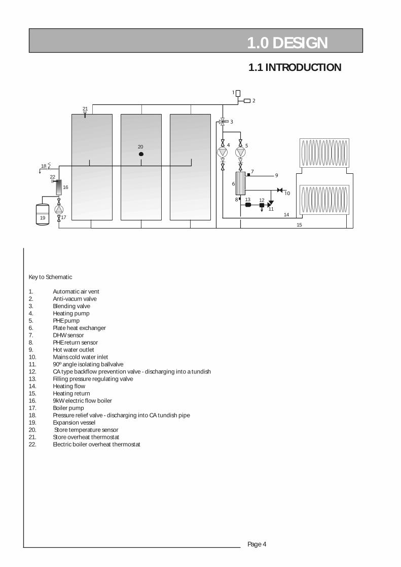
Key to Schematic
1. Automatic air vent2. Anti-vacum valve3. Blending valve4. Heating pump5. PHE pump6. Plate heat exchanger7. DHW sensor8. PHE return sensor9. Hot water outlet10. Mains cold water inlet11. 90º angle isolating ballvalve12. CA type backflow prevention valve - discharging into a tundish13. Filling pressure regulating valve14. Heating flow15. Heating return16. 9kW electric flow boiler17. Boiler pump18. Pressure relief valve - discharging into CA tundish pipe19. Expansion vessel20. Store temperature sensor21. Store overheat thermostat22. Electric boiler overheat thermostat
12
1114
15
17
18
19
20
21
22
16
13
Page 5
ELEC
TRA
MAT
E 20
00
1.0 DESIGN
ELBATNOITCELESLEDOM
ffiraTylppuSyticirtcelE
ssoltaehngisedmumixaM)Wk(gnillewdfo
MEledoM072
MEledoM071
)7ymonocE(ylnokaep-ffoemitthginh7 0.4 5.2
ruoh3,emitthginruoh5(kaep-ffoh01)01ymonocE()gnineveruoh2dnanoonretfa
0.6 5.3
ruoh2nahteromtonhtiwkaepffo+h81ymonocE(sdoirepkaep-ffoneewteblavretni
)815.7 0.5
epytytreporPsmoordebforebmuN*
smoorrewohs/smoorhtabforebmuN*3-1
2/12-1
1/1
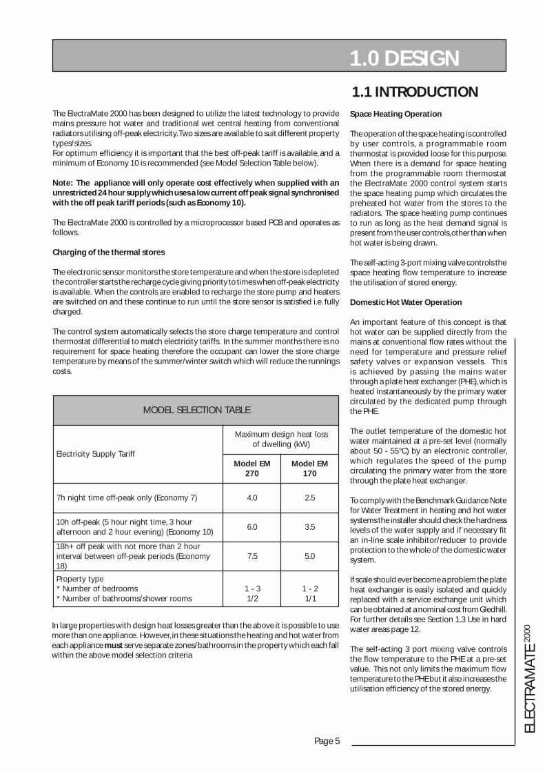
1.1 INTRODUCTIONThe ElectraMate 2000 has been designed to utilize the latest technology to provide mains pressure hot water and traditional wet central heating from conventional radiators utilising off-peak electricity. Two sizes are available to suit different property types/sizes.For optimum effi ciency it is important that the best off-peak tariff is available, and a minimum of Economy 10 is recommended (see Model Selection Table below).
Note: The appliance will only operate cost effectively when supplied with an unrestricted 24 hour supply which uses a low current off peak signal synchronised with the off peak tariff periods (such as Economy 10).
The ElectraMate 2000 is controlled by a microprocessor based PCB and operates as follows.
Charging of the thermal stores
The electronic sensor monitors the store temperature and when the store is depleted the controller starts the recharge cycle giving priority to times when off-peak electricity is available. When the controls are enabled to recharge the store pump and heaters are switched on and these continue to run until the store sensor is satisfi ed i.e. fully charged.
The control system automatically selects the store charge temperature and control thermostat differential to match electricity tariffs. In the summer months there is no requirement for space heating therefore the occupant can lower the store charge temperature by means of the summer/winter switch which will reduce the runnings costs.
Space Heating Operation
The operation of the space heating is controlled by user controls, a programmable room thermostat is provided loose for this purpose. When there is a demand for space heating from the programmable room thermostat the ElectraMate 2000 control system starts the space heating pump which circulates the preheated hot water from the stores to the radiators. The space heating pump continues to run as long as the heat demand signal is present from the user controls, other than when hot water is being drawn.
The self-acting 3-port mixing valve controls the space heating fl ow temperature to increase the utilisation of stored energy.
Domestic Hot Water Operation
An important feature of this concept is that hot water can be supplied directly from the mains at conventional fl ow rates without the need for temperature and pressure relief safety valves or expansion vessels. This is achieved by passing the mains water through a plate heat exchanger (PHE), which is heated instantaneously by the primary water circulated by the dedicated pump through the PHE.
The outlet temperature of the domestic hot water maintained at a pre-set level (normally about 50 - 55°C) by an electronic controller, which regulates the speed of the pump circulating the primary water from the store through the plate heat exchanger.
To comply with the Benchmark Guidance Note for Water Treatment in heating and hot water systems the installer should check the hardness levels of the water supply and if necessary fi t an in-line scale inhibitor/reducer to provide protection to the whole of the domestic water system.
If scale should ever become a problem the plate heat exchanger is easily isolated and quickly replaced with a service exchange unit which can be obtained at a nominal cost from Gledhill. For further details see Section 1.3 Use in hard water areas page 12.
The self-acting 3 port mixing valve controls the fl ow temperature to the PHE at a pre-set value. This not only limits the maximum fl ow temperature to the PHE but it also increases the utilisation effi ciency of the stored energy.
In large properties with design heat losses greater than the above it is possible to use more than one appliance. However, in these situations the heating and hot water from each appliance must serve separate zones/bathrooms in the property which each fall within the above model selection criteria

Page 6
1.0 DESIGN 1.2 TECHNICAL DATA
LEDOM 072ME 071ME
emuloverotsyramirP sertil 072 071
thgieWytpmE*
lluF*
)gk(59553
57542
erusserpcitatsdettimrepmumixaMerotslamrehT*
tiucricgnitaeH*retawtohcitsemoD*
)rab(0.30.30.5
egnarerusserpgnikroWerotslamrehT*
tiucricgnitaeH*retawtohcitsemoD*
)rab(5.2-5.05.2-5.00.3-5.1
metsySgnilliFcitamotuA )rab( *5.1
evlavfeilererusserP tiucricgnitaehdnaerots- rab0.3taetarepoottesyrotcaf-"½
lessevnoisnapxEerusserpegrahclessevlaitinI*
)dednemmocer(erusserpegrahcmetsyslaitinI*emulovlessevnoisnapxE*
ezislessevnoisnapxE*
)rab()rab()sertil()mm(
0.10.104
055x023
0.10.152
005x092
atadngisedmetsySerutarepmetegrahcerotS*
wolf-tiucricgnitaeH*nruter-tiucricgnitaeH*
teltuoretawtohcitsemoD*erusserpegrahcmetsysgnitaehlaitinI*
erusserpgnitarepometsysgnitaehlamroN*etarwolfretawtohmumixaM*
)C°(
)C°()C°()C°()rab()rab()nim/l(
ybdetcelesyllacitamotuA(58-55dnamedhctamotmetsyslortnoc
)ffiratyticirtceledna28
)mumixam(17)elbatsujdaresunoN(55
0.15.2-0.1
53
rofelbaTnoitceleSledoMees(daolgnitaehngisedmumixaM*)sliatedrehtruf
)Wk( 5.7 0.5
)llA(spmuP*evlavgnidnelbtrop-3gnitcafleS*
tatsomrehttaehrevoerotS*tatsomrehttaehrevoreliobcirtcelE*
)ecivedpupototuafotrap(evlavAC*)ecivedpupototuafotrap(rotalugererusserP*
yrettabretaeH*BCPniaM*
BCPkaep-ffO*
05-51SPUsofdnurGH43-MC-16ximauqA
460TGllihdelG460TGllihdelG
retneverpwolfkcaB"½C9ACtinullifmetsys3402BA-KStamilA
rab0.1tatesyrotcafretaehenilniWk9llihdelG
551TGllihdelG951TGllihdelG
snoitcennocepiPwolfgnitaeH*
nrutergnitaeH*wolfretawtoH*
ylppussniamretawdloC*)feilererusserp(epipegrahcsiD*
erots-niarD*yrettabretaeh-niarD*
hsidnutmorfegrahcsiD*
reppoc-mm22reppoc-mm22reppoc-mm22reppoc-mm22
epipegrahcsidotnireppoc-mm51hsidnutwoleb
"½"½
reppoc-mm22
ylppuSyticirtcelEv032@gnitaRWk*
V032@tnerruclanimoN*
)Wk(
)A(
Wk05.0+sretaehWk0.9(5.9tiucricyrallixua
3.14
1. The flow rates quoted are based on a 35°C temperature rise and assumes the minimum recommended working pressure and adequate flow are available at the connection to the appliance.2. The expansion vessel is separate from the appliance complete with a manual air vent/connector. This must be connected on site by the installer.3. The domestic hot water outlet temperature is automatically regulated to approximately 55ºC at the bath flow rate of 18 litres/min recommended by BS6700. The temperature is not user adjustable.* Minimum water supply pressure at the connection to the appliance under simultaneous demand conditions. (2.0 bar recommended)
Page 7
ELEC
TRA
MAT
E 20
00
27
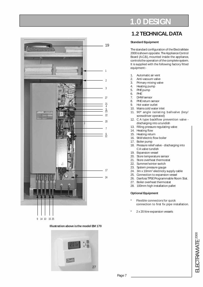
Illustration above is the model EM 170
19
1
2
3
27
2145
2322
20
7
612
17
24
9 14 10 15 25
1.2 TECHNICAL DATA
Standard Equipment
The standard confi guration of the ElectraMate 2000 is shown opposite. The Appliance Control Board (A.C.B.), mounted inside the appliance, controls the operation of the complete system. It is supplied with the following factory fi tted equipment:-
1. Automatic air vent2. Anti-vacuum valve3. Primary mixing valve4. Heating pump5. PHE pump6. PHE7. DHW sensor8. PHE return sensor9. Hot water outlet10. Mains cold water inlet11. 90º angle isolating ballvalve (key/ screwdriver operated)12. C A type backflow prevention valve - discharging into a tundish13. Filling pressure regulating valve14. Heating fl ow15. Heating return16. 9kW electric fl ow boiler17. Boiler pump18. Pressure relief valve - discharging into C A valve tundish19. Expansion vessel20. Store temperature sensor21. Store overheat thermostat22. Summer/winter switch23. System pressure gauge24. 3m x 10mm2 electricity supply cable25. Connection to expansion vessel26. Danfoss TP5E Programmable Room Stat.27. Boiler overheat thermostat28. 100mm high installation pallet
Optional Equipment
* Flexible connectors for quick connection to fi rst fi x pipe installation. * 2 x 20 litre expansion vessels
1.0 DESIGN
Page 8
1.0 DESIGN
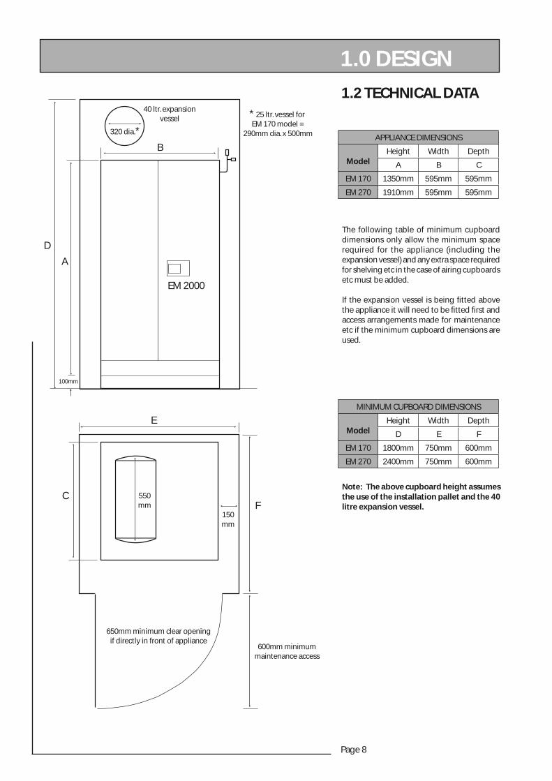
1.2 TECHNICAL DATA
The following table of minimum cupboard dimensions only allow the minimum space required for the appliance (including the expansion vessel) and any extra space required for shelving etc in the case of airing cupboards etc must be added.
If the expansion vessel is being fi tted above the appliance it will need to be fi tted fi rst and access arrangements made for maintenance etc if the minimum cupboard dimensions are used.
EM 2000
A
D
B
320 dia.*
550mm
CF
150mm
E
600mm minimummaintenance access
650mm minimum clear openingif directly in front of appliance
40 ltr. expansionvessel * 25 ltr. vessel for
EM 170 model = 290mm dia. x 500mm
100mm
Note: The above cupboard height assumes the use of the installation pallet and the 40 litre expansion vessel.
APPLIANCE DIMENSIONS
ModelHeight Width Depth
A B C
EM 170 1350mm 595mm 595mm
EM 270 1910mm 595mm 595mm
MINIMUM CUPBOARD DIMENSIONS
ModelHeight Width Depth
D E F
EM 170 1800mm 750mm 600mm
EM 270 2400mm 750mm 600mm
Page 9
ELEC
TRA
MAT
E 20
00
1.0 DESIGN
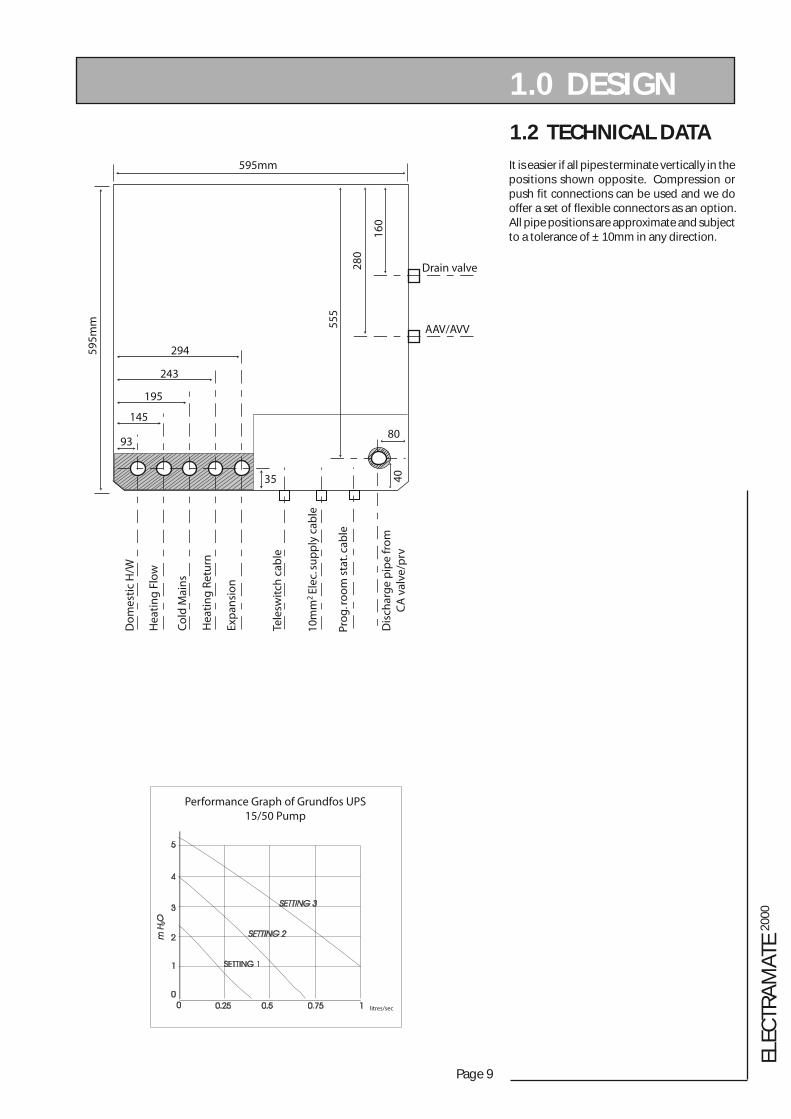
1.2 TECHNICAL DATA
It is easier if all pipes terminate vertically in the positions shown opposite. Compression or push fit connections can be used and we do offer a set of flexible connectors as an option. All pipe positions are approximate and subject to a tolerance of ± 10mm in any direction.
litres/sec
Performance Graph of Grundfos UPS15/50 Pump
Page 10
1.0 DESIGN
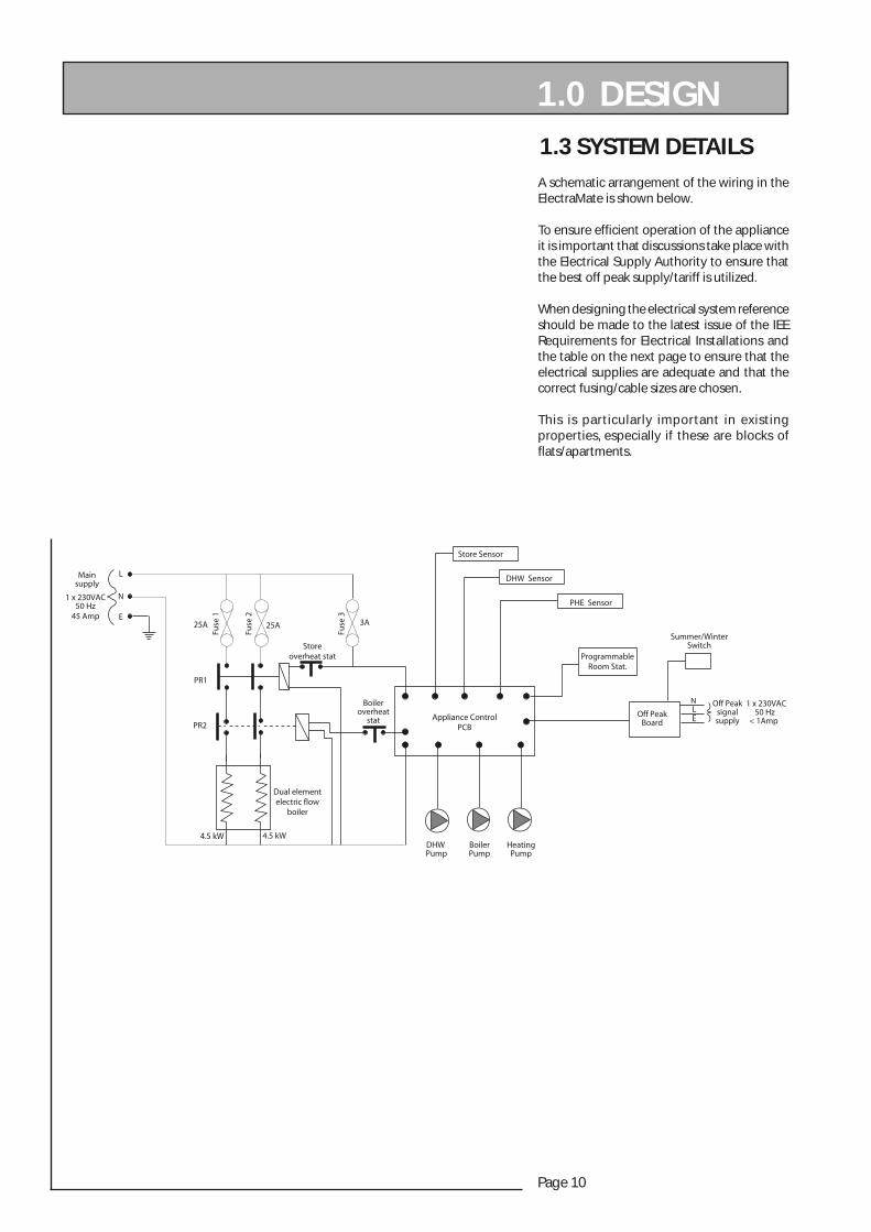
1.3 SYSTEM DETAILS
A schematic arrangement of the wiring in the ElectraMate is shown below.
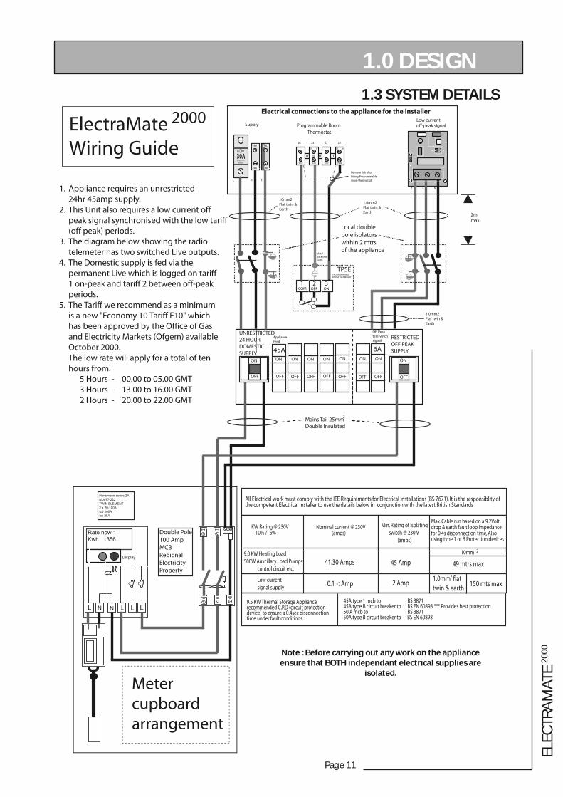
To ensure efficient operation of the appliance it is important that discussions take place with the Electrical Supply Authority to ensure that the best off peak supply/tariff is utilized.
When designing the electrical system reference should be made to the latest issue of the IEE Requirements for Electrical Installations and the table on the next page to ensure that the electrical supplies are adequate and that the correct fusing/cable sizes are chosen.
This is particularly important in existing properties, especially if these are blocks of flats/apartments.
DHW Pump
BoilerPump
HeatingPump
Storeoverheat stat
Boileroverheat
stat Appliance ControlPCB
PR1
PR2
25A 25A 3A
Fuse
1
Fuse
2
Fuse
3
L
E
N
Off PeakBoard
Off Peaksignalsupply
Mainsupply
1 x 230VAC50 Hz
1 x 230VAC50 Hz
45 Amp
4.5 kW 4.5 kW
Summer/WinterSwitch
Store Sensor
DHW Sensor
PHE Sensor
NLE < 1Amp
ProgrammableRoom Stat.
Dual elementelectric flow
boiler
Page 11
ELEC
TRA
MAT
E 20
00
1.3 SYSTEM DETAILS
1.0 DESIGN
Note : Before carrying out any work on the appliance ensure that BOTH independant electrical supplies are
isolated.
Page 12
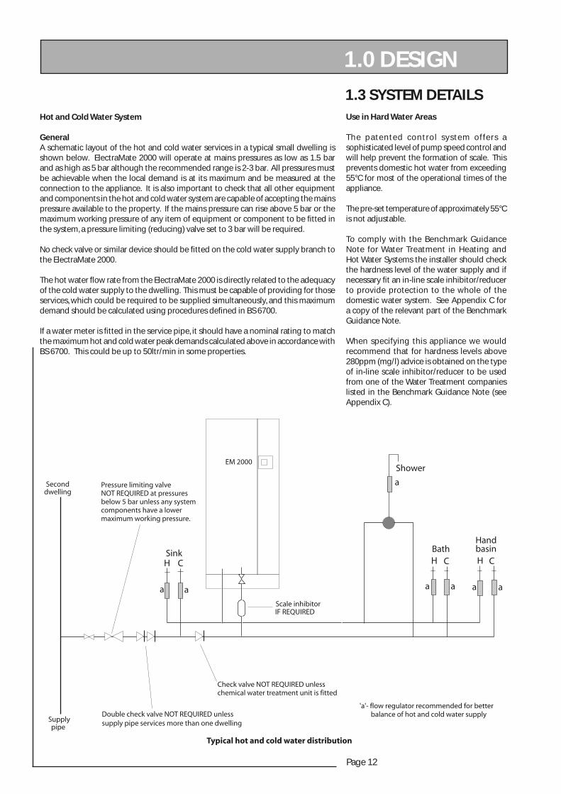
1.3 SYSTEM DETAILSUse in Hard Water Areas
The patented control system offers a sophisticated level of pump speed control and will help prevent the formation of scale. This prevents domestic hot water from exceeding 55°C for most of the operational times of the appliance.
The pre-set temperature of approximately 55°C is not adjustable.
To comply with the Benchmark Guidance Note for Water Treatment in Heating and Hot Water Systems the installer should check the hardness level of the water supply and if necessary fi t an in-line scale inhibitor/reducer to provide protection to the whole of the domestic water system. See Appendix C for a copy of the relevant part of the Benchmark Guidance Note.
When specifying this appliance we would recommend that for hardness levels above 280ppm (mg/l) advice is obtained on the type of in-line scale inhibitor/reducer to be used from one of the Water Treatment companies listed in the Benchmark Guidance Note (see Appendix C).
Hot and Cold Water System
General A schematic layout of the hot and cold water services in a typical small dwelling is shown below. ElectraMate 2000 will operate at mains pressures as low as 1.5 bar and as high as 5 bar although the recommended range is 2-3 bar. All pressures must be achievable when the local demand is at its maximum and be measured at the connection to the appliance. It is also important to check that all other equipment and components in the hot and cold water system are capable of accepting the mains pressure available to the property. If the mains pressure can rise above 5 bar or the maximum working pressure of any item of equipment or component to be fi tted in the system, a pressure limiting (reducing) valve set to 3 bar will be required.
No check valve or similar device should be fi tted on the cold water supply branch to the ElectraMate 2000.
The hot water fl ow rate from the ElectraMate 2000 is directly related to the adequacy of the cold water supply to the dwelling. This must be capable of providing for those services, which could be required to be supplied simultaneously, and this maximum demand should be calculated using procedures defi ned in BS 6700.
If a water meter is fi tted in the service pipe, it should have a nominal rating to match the maximum hot and cold water peak demands calculated above in accordance with BS 6700. This could be up to 50ltr/min in some properties.
1.0 DESIGN

Page 13
ELEC
TRA
MAT
E 20
00
1.3 SYSTEM DETAILSHot and Cold Water System
Pipe Sizing / Materials
To achieve even distribution of the available supply of hot and cold water, it is important in any mains pressure system, that the piping in a dwelling should be sized in accordance with BS 6700.
However, the following rule of thumb guide lines should be adequate for most smaller property types as long as water pressures are within the recommended range of 2-3 bar.
1. A 15mm copper or equivalent external service may be sufficient for a small 1bathroom dwelling (depending upon the flow rate available), but the minimum recommended size for new dwellings is 22mm (25mm MDPE).2. The internal cold feed from the main incoming stop tap to the ElectraMate should be run in 22mm pipe. The cold main and hot draw-off should also be run in 22mm as far as the branch to the bath tap. 3. The fi nal branches to the hand basins and sinks should be in 10mm and to the baths and showers in 15mm. (1 metre minimum)4. We would recommend that best results for a balanced system are achieved by fi tting appropriate fl ow regulators to each hot and cold outlet. This is particularly relevant where the water pressures are above the recommended water pressure range of 2-3 bar. (See Appendix 1 for further details.
Note: If manifolds (available as an optional extra) are being used suitable fl ow regulators are automatically provided in the manifold and do not need to be provided at each outlet - See Appendix B for further details.
All the recommendations with regard to pipework systems in this manual are generally based on the use of BS/EN Standard copper pipework and fi ttings.
However, we are happy that plastic pipework systems can be used in place of copper internally as long as the chosen system is recommended for use on domestic hot and cold water systems by the manufacturer and is installed fully in accordance with their recommendations.
This is particularly important in relation to use of push fi t connections when using the optional fl exible hose kits - see 2.2 Installation, Pipework connections.
It is also essential that if an alternative pipework material/system is chosen the manufacturer confi rms that the design criteria of the new system is at least equivalent to the use of BS/EN Standard copper pipework and fi ttings.
Taps/Shower Fittings
Aerated taps are recommended to prevent splashing.Any type of shower mixing valve can be used as long as both the hot and cold supplies are mains fed. However, all mains pressure systems are subject to dynamic changes particularly when other hot and cold taps/showers are opened and closed, which will cause changes in the water temperature at mixed water outlets such as showers. For this reason and because these are now no more expensive than a manual shower we only recommend the use of thermostatic showers with this appliance, even if these are the over the bath/telephone handset type.The shower head provided must also be suitable for mains pressure supplies.
1.0 DESIGN
The hot water supply to a shower-mixing valve should be fed wherever practical directly from the ElectraMate 2000 or be the fi rst draw-off point on the hot circuit. The cold supply to a shower-mixing valve should wherever practical be fed directly from the rising mains via an independent branch. The shower must incorporate or be fi tted with the necessary check valves to provide back-syphonage protection in accordance with the Water Regulations.
The supply of hot and cold mains water directly to a bidet is permitted provided that it is of the over-rim fl ushing type and that a type ‘A’ air gap is incorporated.
Hot and Cold Water System
If the length of the hot water draw off pipework is excessive and the delivery time will be more than 30 seconds before hot water is available at the tap, you may wish to consider using trace heating to the hot water pipework such as the Raychem HWAT system. Please consult Gledhill Technical Department for further details.
Please note that the ElectraMate 2000 is NOT suitable for use with a secondary domestic hot water circulation system.
It is important that the cold water pipework is adequately separated/protected from any heating/hot water pipework to ensure that the water remains cold and of drinking water quality.

Page 14
1.0 DESIGN
Heating System
General
A schematic layout of the heating system in a typical small dwelling is shown opposite.
The heating circuit is taken from the ElectraMate 2000 and is piped in the conventional manner.
The ElectraMate 2000 is only suitable for a sealed heating system. Therefore heating circuit pipework can run at a higher level than the appliance if required as long as suitable air vents are provided.
If any radiators are located above the level of the ElectraMate 2000 the system should be designed so that gravity circulation does not occur when the heating pump is not running. To be certain of preventing this it is recommended that a check valve, or valves, are fi tted on the vertical fl ow pipes.
The heating circuit operates on the normal primary boiler temperatures i.e. 82°C fl ow and 71°C return. Therefore any traditional hot water radiators or convectors can be used with this system and it is recommended that they are sized in accordance with BS EN 442.
The Grundfos 15/50 pump characteristics are shown in 1.2 Technical Data. Approximately all the head can be used when sizing the heating circuit pipework.
All the recommendations with regard to pipework systems in this manual are generally based on the use of BS/EN Standard copper pipework and fi ttings.
However, we are happy that plastic pipework systems can be used in place of copper internally as long as the chosen system is recommended for use on domestic heating systems by the manufacturer and is installed fully in accordance with their recommendations. We always recommend the use of barrier pipe for these systems.
It is also essential that if an alternative pipework material/system is chosen the manufacturer confi rms that the design criteria of the new system is at least equivalent to the use of BS/EN Standard copper pipework and fi ttings.
1.3 SYSTEM DETAILS
EM 2000
Expansion vessel
Air vent
Full bore auto bypass valve NOT REQUIREDunless the heating system incorporatesmechanical thermostatic control valves e.g.T.R.V's to all radiators or 2 port zone valves.As an alternative one of the radiators can befitted with lockshield valves which are leftfully open, permanently.
Page 15
ELEC
TRA
MAT
E 20
00
1.0 DESIGN 1.3 SYSTEM DETAILS
h-thgieH)M(
eziSepiPmumixaM
)M(eL
2.0
mm51 1
mm22 9
mm82 03
3.0
mm51 2
mm22 31
mm82 54
4.0
mm51 3
mm22 91
mm82 36
6.0
mm51 4
mm22 72
mm82 49
8.0
mm22 5
mm22 73
mm82 721
1
mm51 7
mm22 64
mm82 751
h Le
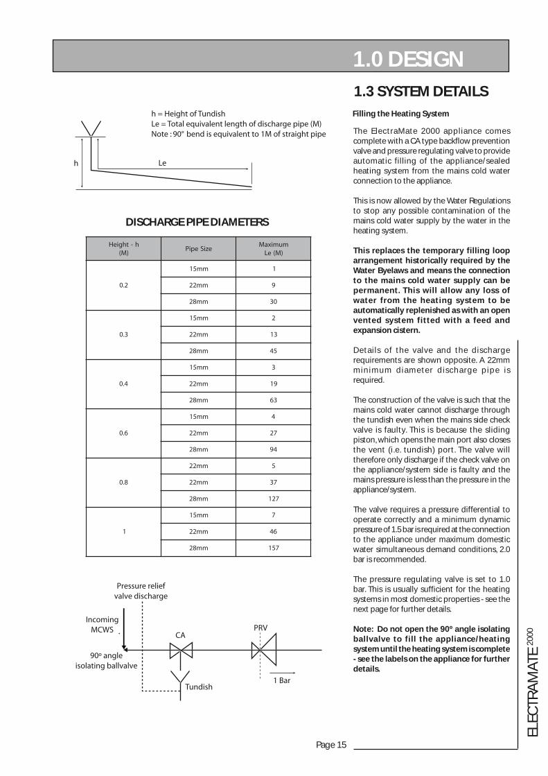
h = Height of TundishLe = Total equivalent length of discharge pipe (M)Note : 90° bend is equivalent to 1M of straight pipe
DISCHARGE PIPE DIAMETERS
The ElectraMate 2000 appliance comes complete with a CA type backflow prevention valve and pressure regulating valve to provide automatic filling of the appliance/sealed heating system from the mains cold water connection to the appliance.
This is now allowed by the Water Regulations to stop any possible contamination of the mains cold water supply by the water in the heating system.
This replaces the temporary filling loop arrangement historically required by the Water Byelaws and means the connection to the mains cold water supply can be permanent. This will allow any loss of water from the heating system to be automatically replenished as with an open vented system fitted with a feed and expansion cistern.
Details of the valve and the discharge requirements are shown opposite. A 22mm minimum diameter discharge pipe is required.
The construction of the valve is such that the mains cold water cannot discharge through the tundish even when the mains side check valve is faulty. This is because the sliding piston, which opens the main port also closes the vent (i.e. tundish) port. The valve will therefore only discharge if the check valve on the appliance/system side is faulty and the mains pressure is less than the pressure in the appliance/system.
The valve requires a pressure differential to operate correctly and a minimum dynamic pressure of 1.5 bar is required at the connection to the appliance under maximum domestic water simultaneous demand conditions, 2.0 bar is recommended.
The pressure regulating valve is set to 1.0 bar. This is usually sufficient for the heating systems in most domestic properties - see the next page for further details.
Note: Do not open the 90º angle isolating ballvalve to fill the appliance/heating system until the heating system is complete - see the labels on the appliance for further details.
Filling the Heating System
1 Bar
PRVCA
IncomingMCWS
Tundish
Pressure reliefvalve discharge
90º angleisolating ballvalve
Page 16
1.0 DESIGN
1.3 SYSTEM DETAILS
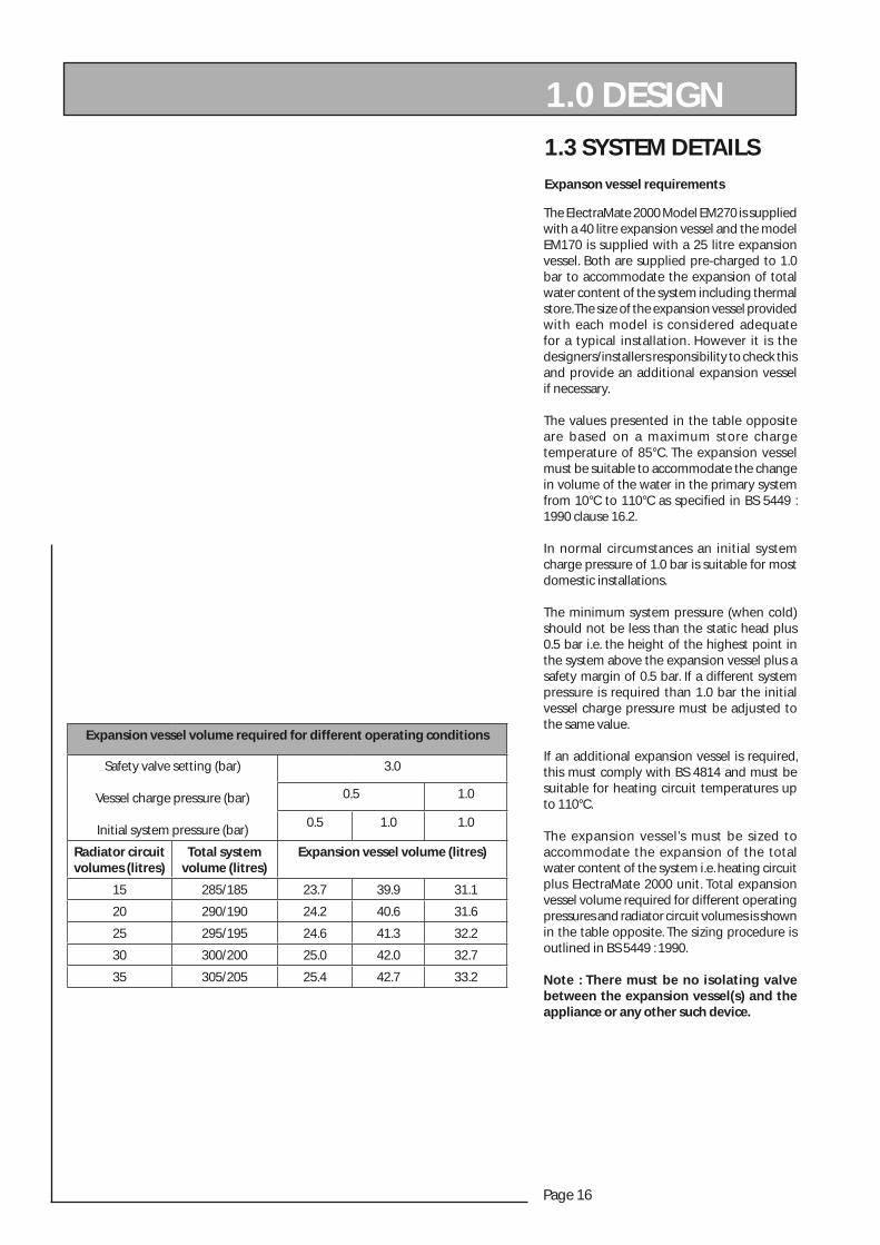
Expanson vessel requirements
The ElectraMate 2000 Model EM270 is supplied with a 40 litre expansion vessel and the model EM170 is supplied with a 25 litre expansion vessel. Both are supplied pre-charged to 1.0 bar to accommodate the expansion of total water content of the system including thermal store. The size of the expansion vessel provided with each model is considered adequate for a typical installation. However it is the designers/installers responsibility to check this and provide an additional expansion vessel if necessary.
The values presented in the table opposite are based on a maximum store charge temperature of 85°C. The expansion vessel must be suitable to accommodate the change in volume of the water in the primary system from 10°C to 110°C as specifi ed in BS 5449 : 1990 clause 16.2.
In normal circumstances an initial system charge pressure of 1.0 bar is suitable for most domestic installations.
The minimum system pressure (when cold) should not be less than the static head plus 0.5 bar i.e. the height of the highest point in the system above the expansion vessel plus a safety margin of 0.5 bar. If a different system pressure is required than 1.0 bar the initial vessel charge pressure must be adjusted to the same value.
If an additional expansion vessel is required, this must comply with BS 4814 and must be suitable for heating circuit temperatures up to 110°C.
The expansion vessel’s must be sized to accommodate the expansion of the total water content of the system i.e. heating circuit plus ElectraMate 2000 unit. Total expansion vessel volume required for different operating pressures and radiator circuit volumes is shown in the table opposite. The sizing procedure is outlined in BS 5449 : 1990.
Note : There must be no isolating valve between the expansion vessel(s) and the appliance or any other such device.
Expansion vessel volume required for different operating conditions
Safety valve setting (bar)
Vessel charge pressure (bar)
Initial system pressure (bar)
3.0
0.5 1.0
0.5 1.0 1.0
Radiator circuit volumes (litres)
Total systemvolume (litres)
Expansion vessel volume (litres)
15 285/185 23.7 39.9 31.1
20 290/190 24.2 40.6 31.6
25 295/195 24.6 41.3 32.2
30 300/200 25.0 42.0 32.7
35 305/205 25.4 42.7 33.2
Page 17
ELEC
TRA
MAT
E 20
00
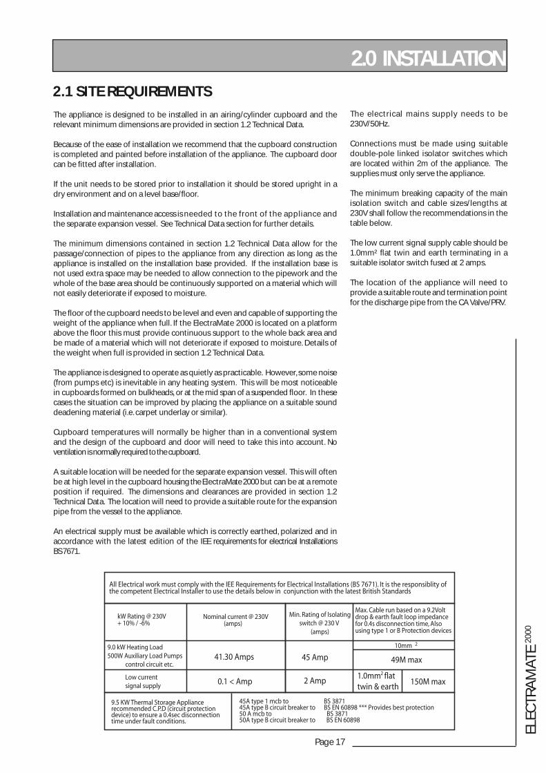
The electrical mains supply needs to be 230V/50Hz.
Connections must be made using suitable double-pole linked isolator switches which are located within 2m of the appliance. The supplies must only serve the appliance.
The minimum breaking capacity of the main isolation switch and cable sizes/lengths at 230V shall follow the recommendations in the table below.
The low current signal supply cable should be 1.0mm² fl at twin and earth terminating in a suitable isolator switch fused at 2 amps.
The location of the appliance will need to provide a suitable route and termination point for the discharge pipe from the CA Valve/PRV.
2.0 INSTALLATION
2.1 SITE REQUIREMENTS
The appliance is designed to be installed in an airing/cylinder cupboard and the relevant minimum dimensions are provided in section 1.2 Technical Data.
Because of the ease of installation we recommend that the cupboard construction is completed and painted before installation of the appliance. The cupboard door can be fi tted after installation.
If the unit needs to be stored prior to installation it should be stored upright in a dry environment and on a level base/fl oor.
Installation and maintenance access is needed to the front of the appliance and the separate expansion vessel. See Technical Data section for further details.
The minimum dimensions contained in section 1.2 Technical Data allow for the passage/connection of pipes to the appliance from any direction as long as the appliance is installed on the installation base provided. If the installation base is not used extra space may be needed to allow connection to the pipework and the whole of the base area should be continuously supported on a material which will not easily deteriorate if exposed to moisture.
The fl oor of the cupboard needs to be level and even and capable of supporting the weight of the appliance when full. If the ElectraMate 2000 is located on a platform above the fl oor this must provide continuous support to the whole back area and be made of a material which will not deteriorate if exposed to moisture. Details of the weight when full is provided in section 1.2 Technical Data.
The appliance is designed to operate as quietly as practicable. However, some noise (from pumps etc) is inevitable in any heating system. This will be most noticeable in cupboards formed on bulkheads, or at the mid span of a suspended fl oor. In these cases the situation can be improved by placing the appliance on a suitable sound deadening material (i.e. carpet underlay or similar).
Cupboard temperatures will normally be higher than in a conventional system and the design of the cupboard and door will need to take this into account. No ventilation is normally required to the cupboard.
A suitable location will be needed for the separate expansion vessel. This will often be at high level in the cupboard housing the ElectraMate 2000 but can be at a remote position if required. The dimensions and clearances are provided in section 1.2 Technical Data. The location will need to provide a suitable route for the expansion pipe from the vessel to the appliance.
An electrical supply must be available which is correctly earthed, polarized and in accordance with the latest edition of the IEE requirements for electrical Installations BS 7671.
All Electrical work must comply with the IEE Requirements for Electrical Installations (BS 7671). It is the responsiblity of the competent Electrical Installer to use the details below in conjunction with the latest British Standards
Min. Rating of Isolatingswitch @ 230 V
(amps)
Max. Cable run based on a 9.2Voltdrop & earth fault loop impedancefor 0.4s disconnection time, Alsousing type 1 or B Protection devices
10mm 2
49M max
150M max1.0mm flattwin & earth
2
45 Amp
2 Amp
45A type 1 mcb to BS 387145A type B circuit breaker to BS EN 60898 *** Provides best protection50 A mcb to BS 387150A type B circuit breaker to BS EN 60898
9.5 KW Thermal Storage Appliance recommended C.P.D (circuit protection device) to ensure a 0.4sec disconnection time under fault conditions.
kW Rating @ 230V+ 10% / -6%
9.0 kW Heating Load500W Auxiliary Load Pumps control circuit etc.
Low currentsignal supply
Nominal current @ 230V (amps)
41.30 Amps
0.1 < Amp
Page 18
2.2 INSTALLATION
2.0 INSTALLATION
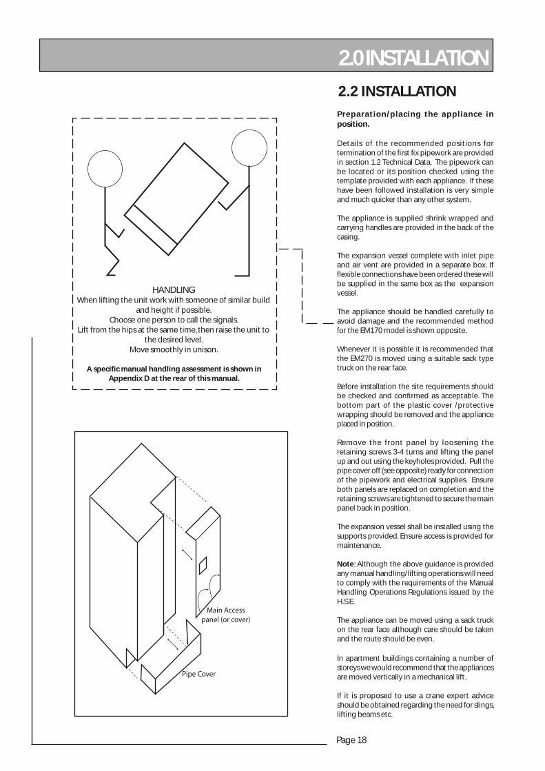
HANDLINGWhen lifting the unit work with someone of similar build
and height if possible. Choose one person to call the signals.
Lift from the hips at the same time, then raise the unit to the desired level.
Move smoothly in unison.
Preparation/placing the appliance in position.
Details of the recommended positions for termination of the fi rst fi x pipework are provided in section 1.2 Technical Data. The pipework can be located or its position checked using the template provided with each appliance. If these have been followed installation is very simple and much quicker than any other system.
The appliance is supplied shrink wrapped and carrying handles are provided in the back of the casing.
The expansion vessel complete with inlet pipe and air vent are provided in a separate box. If fl exible connections have been ordered these will be supplied in the same box as the expansion vessel.
The appliance should be handled carefully to avoid damage and the recommended method for the EM170 model is shown opposite.
Whenever it is possible it is recommended that the EM270 is moved using a suitable sack type truck on the rear face.
Before installation the site requirements should be checked and confi rmed as acceptable. The bottom part of the plastic cover /protective wrapping should be removed and the appliance placed in position.
Remove the front panel by loosening the retaining screws 3-4 turns and lifting the panel up and out using the keyholes provided. Pull the pipe cover off (see opposite) ready for connection of the pipework and electrical supplies. Ensure both panels are replaced on completion and the retaining screws are tightened to secure the main panel back in position.
The expansion vessel shall be installed using the supports provided. Ensure access is provided for maintenance.
Note: Although the above guidance is provided any manual handling/lifting operations will need to comply with the requirements of the Manual Handling Operations Regulations issued by the H.S.E.
The appliance can be moved using a sack truck on the rear face although care should be taken and the route should be even.
In apartment buildings containing a number of storeys we would recommend that the appliances are moved vertically in a mechanical lift.
If it is proposed to use a crane expert advice should be obtained regarding the need for slings, lifting beams etc.
Pipe Cover
Main Accesspanel (or cover)
A specific manual handling assessment is shown in Appendix D at the rear of this manual.
Page 19
ELEC
TRA
MAT
E 20
00
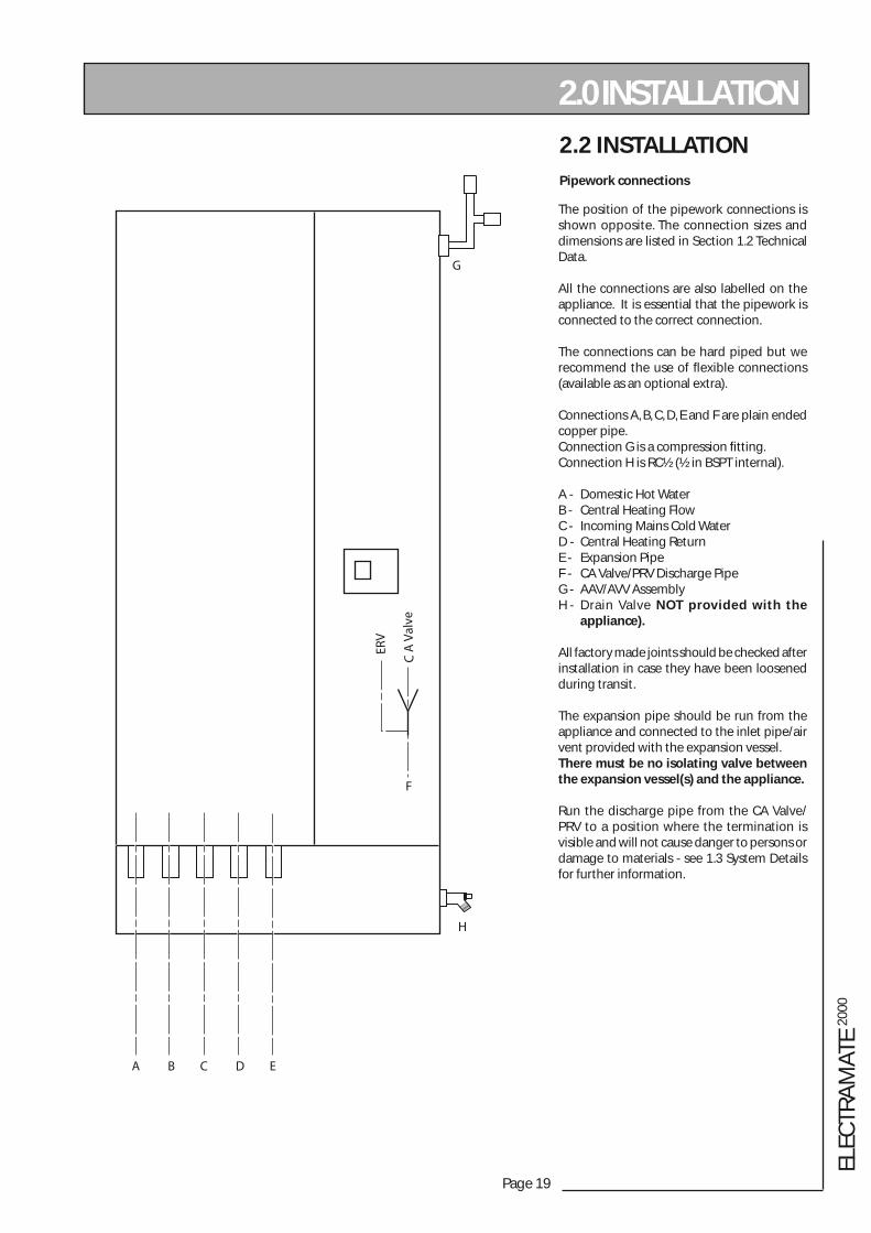
The position of the pipework connections is shown opposite. The connection sizes and dimensions are listed in Section 1.2 Technical Data.
All the connections are also labelled on the appliance. It is essential that the pipework is connected to the correct connection.
The connections can be hard piped but we recommend the use of fl exible connections (available as an optional extra).
Connections A, B, C, D, E and F are plain ended copper pipe.Connection G is a compression fi tting.Connection H is RC½ (½ in BSPT internal).
A - Domestic Hot WaterB - Central Heating FlowC - Incoming Mains Cold WaterD - Central Heating ReturnE - Expansion PipeF - CA Valve/PRV Discharge PipeG - AAV/AVV AssemblyH - Drain Valve NOT provided with the appliance).
All factory made joints should be checked after installation in case they have been loosened during transit.
The expansion pipe should be run from the appliance and connected to the inlet pipe/air vent provided with the expansion vessel.There must be no isolating valve between the expansion vessel(s) and the appliance.
Run the discharge pipe from the CA Valve/PRV to a position where the termination is visible and will not cause danger to persons or damage to materials - see 1.3 System Details for further information.
2.0 INSTALLATION2.2 INSTALLATIONPipework connections
A B C D E
H
G
F
C A
Val
ve
ERV
Page 20
2.2 INSTALLATION
2.0 INSTALLATION
10
0k
CN
1
E L N
SMA0411
470R
0.22uF
PC
81
4
OP
S
v.1
.1
PC
81
4
1
L N E E N L SL E N SL
2 3 4 5 6 7 8 9 10Mains Boiler Boiler pump
11 NC
NSL
1SL
2E
EN
SL
1213
1415
1617
18
DH
W p
ump
Valv
e / h
tg p
ump
20 NL
HW
HTG
EE
LN
SL
2122
2324
2526
2728
Room
ther
mos
tat
Clo
ck /
pro
gra
mm
er
29
+ -T1T2-+T3-+
3031323334353637
PSCFS SAC
Sw1
Sw2
1 2 3 4 5
L N E
L N E
L N E
BR GY BL BLK
B W R R
GY BL BK
BoilerPump
HeatingPump
DHWPump
BL
BR
GY
GY
BL
BR
BR
BR
BR
GY
BL
BLK
Store Sensor
PHE Return SensorDWH Sensor
RRWB
Wiring Key
RBRBLGYBLK
RedBrownBlueGreen/YellowBlack
Cable Cleat
Flat twin and earthPVC cable
10mm2 Feed cable supplied with 3 metres availableexternally to connect to local isolator
ProgrammableRoom Stat.
Remove link whenRoom Stat installed
Teleswitch PCB
Winter - 0
Summer - 1
BR
BL
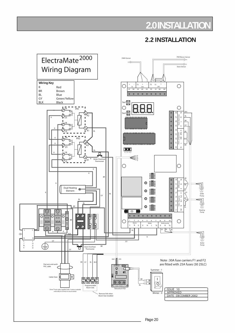
Note : 30A fuse carriers F1 and F2are fitted with 25A fuses (30 25LC)
30A 30A
F1 F2
AC30 AC30
LIV
E
Dual HeatingElement
13
14
14
23
23
24
24
13
Store OverheatThermostat
Boiler OverheatThermostat
R
R
R
R
R
R
R
R
R
R
R
R
RRL L
NN
BL
BL
BL
BL
BL
BL
BLK
BR
BR
BR
BR
GY
GY GY
GY
ISSUE 10
DATE : DECEMBER 2002APPROVED
PR1
PR2
A1
A1
A2
A2
ElectraMate Wiring Diagram
2000
LINE
LOAD
Page 21
ELEC
TRA
MAT
E 20
00
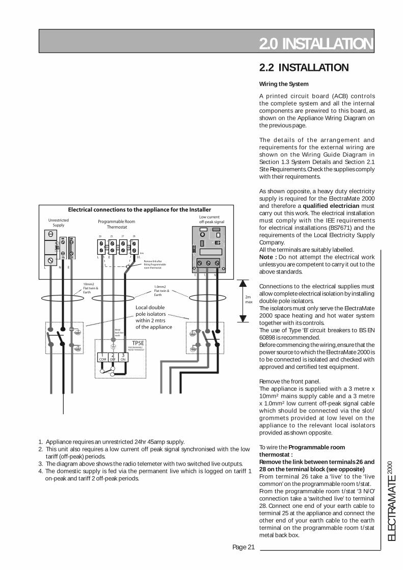
2.2 INSTALLATIONWiring the System
A printed circuit board (ACB) controls the complete system and all the internal components are prewired to this board, as shown on the Appliance Wiring Diagram on the previous page.
The detai ls of the arrangement and requirements for the external wiring are shown on the Wiring Guide Diagram in Section 1.3 System Details and Section 2.1 Site Requirements. Check the supplies comply with their requirements.
As shown opposite, a heavy duty electricity supply is required for the ElectraMate 2000 and therefore a qualified electrician must carry out this work. The electrical installation must comply with the IEE requirements for electrical installations (BS7671) and the requirements of the Local Electricity Supply Company.All the terminals are suitably labelled.Note : Do not attempt the electrical work unless you are competent to carry it out to the above standards.
Connections to the electrical supplies must allow complete electrical isolation by installing double pole isolators.The isolators must only serve the ElectraMate 2000 space heating and hot water system together with its controls.The use of Type ‘B’ circuit breakers to BS EN 60898 is recommended.Before commencing the wiring, ensure that the power source to which the ElectraMate 2000 is to be connected is isolated and checked with approved and certified test equipment.
Remove the front panel.The appliance is supplied with a 3 metre x 10mm² mains supply cable and a 3 metre x 1.0mm² low current off-peak signal cable which should be connected via the slot/grommets provided at low level on the appliance to the relevant local isolators provided as shown opposite.
To wire the Programmable room thermostat :Remove the link between terminals 26 and 28 on the terminal block (see opposite)From terminal 26 take a ‘live’ to the ‘live common’ on the programmable room t/stat.From the programmable room t/stat ‘3 N/O’ connection take a ‘switched live’ to terminal 28. Connect one end of your earth cable to terminal 25 at the appliance and connect the other end of your earth cable to the earth terminal on the programmable room t/stat metal back box.
1. Appliance requires an unrestricted 24hr 45amp supply.2. This unit also requires a low current off peak signal synchronised with the low tariff (off-peak) periods.3. The diagram above shows the radio telemeter with two switched live outputs.4. The domestic supply is fed via the permanent live which is logged on tariff 1 on-peak and tariff 2 off-peak periods.
2.0 INSTALLATION
Page 22
2.2 INSTALLATION
2.0 INSTALLATION
Wiring the system (contd.)
Before switching on the electrical supply check all the factory made terminal connections to ensure they have not become loose during transit.
Note : The appliance is provided with a 4.0mm earth cable from an earthing strap on the primary return (to boiler) pipe to the earth stud on the wiring panel.
WARNING - When the wiring is complete but before switching on the appliance electrically ensure the unit is full of water by checking the air vent on the side of the appliance and ensuring the pressure gauge reads between 0.5 - 1.0 bar. Switch the unit ON and test the operation and then replace the front panel.
Page 23
ELEC
TRA
MAT
E 20
00
2.0 INSTALLATION2.3 COMMISSIONING
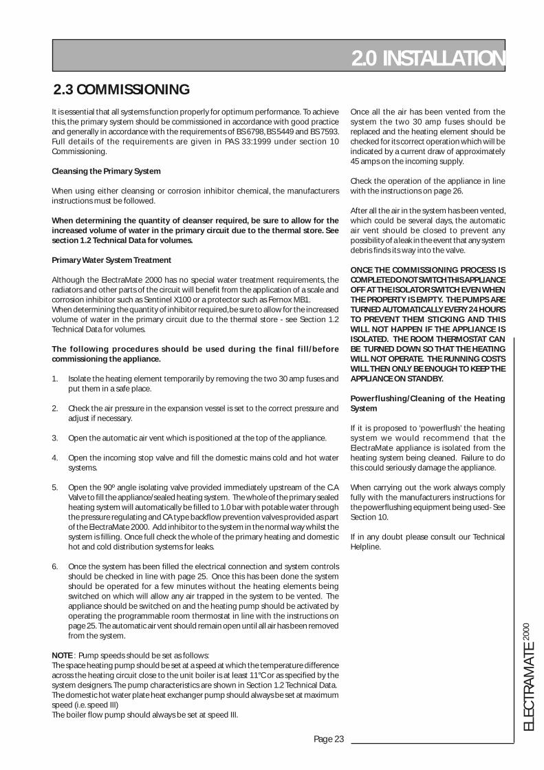
It is essential that all systems function properly for optimum performance. To achieve this, the primary system should be commissioned in accordance with good practice and generally in accordance with the requirements of BS 6798, BS 5449 and BS 7593.Full details of the requirements are given in PAS 33:1999 under section 10 Commissioning.
Cleansing the Primary System
When using either cleansing or corrosion inhibitor chemical, the manufacturers instructions must be followed.
When determining the quantity of cleanser required, be sure to allow for the increased volume of water in the primary circuit due to the thermal store. See section 1.2 Technical Data for volumes.
Primary Water System Treatment
Although the ElectraMate 2000 has no special water treatment requirements, the radiators and other parts of the circuit will benefit from the application of a scale and corrosion inhibitor such as Sentinel X100 or a protector such as Fernox MB1.When determining the quantity of inhibitor required, be sure to allow for the increased volume of water in the primary circuit due to the thermal store - see Section 1.2 Technical Data for volumes.
The following procedures should be used during the final fill/before commissioning the appliance.
1. Isolate the heating element temporarily by removing the two 30 amp fuses and put them in a safe place.
2. Check the air pressure in the expansion vessel is set to the correct pressure and adjust if necessary.
3. Open the automatic air vent which is positioned at the top of the appliance.
4. Open the incoming stop valve and fill the domestic mains cold and hot water systems.
5. Open the 90º angle isolating valve provided immediately upstream of the C.A Valve to fill the appliance/sealed heating system. The whole of the primary sealed heating system will automatically be filled to 1.0 bar with potable water through the pressure regulating and CA type backflow prevention valves provided as part of the ElectraMate 2000. Add inhibitor to the system in the normal way whilst the system is filling. Once full check the whole of the primary heating and domestic hot and cold distribution systems for leaks.
6. Once the system has been filled the electrical connection and system controls should be checked in line with page 25. Once this has been done the system should be operated for a few minutes without the heating elements being switched on which will allow any air trapped in the system to be vented. The appliance should be switched on and the heating pump should be activated by operating the programmable room thermostat in line with the instructions on page 25. The automatic air vent should remain open until all air has been removed from the system.
NOTE : Pump speeds should be set as follows:The space heating pump should be set at a speed at which the temperature difference across the heating circuit close to the unit boiler is at least 11°C or as specified by the system designers. The pump characteristics are shown in Section 1.2 Technical Data.The domestic hot water plate heat exchanger pump should always be set at maximum speed (i.e. speed III)The boiler flow pump should always be set at speed III.
Once all the air has been vented from the system the two 30 amp fuses should be replaced and the heating element should be checked for its correct operation which will be indicated by a current draw of approximately 45 amps on the incoming supply.
Check the operation of the appliance in line with the instructions on page 26.
After all the air in the system has been vented, which could be several days, the automatic air vent should be closed to prevent any possibility of a leak in the event that any system debris finds its way into the valve.
ONCE THE COMMISSIONING PROCESS IS COMPLETE DO NOT SWITCH THIS APPLIANCE OFF AT THE ISOLATOR SWITCH EVEN WHEN THE PROPERTY IS EMPTY. THE PUMPS ARE TURNED AUTOMATICALLY EVERY 24 HOURS TO PREVENT THEM STICKING AND THIS WILL NOT HAPPEN IF THE APPLIANCE IS ISOLATED. THE ROOM THERMOSTAT CAN BE TURNED DOWN SO THAT THE HEATING WILL NOT OPERATE. THE RUNNING COSTS WILL THEN ONLY BE ENOUGH TO KEEP THE APPLIANCE ON STANDBY.
Powerflushing/Cleaning of the Heating System
If it is proposed to ‘powerflush’ the heating system we would recommend that the ElectraMate appliance is isolated from the heating system being cleaned. Failure to do this could seriously damage the appliance.
When carrying out the work always comply fully with the manufacturers instructions for the powerflushing equipment being used- See Section 10.
If in any doubt please consult our Technical Helpline.
Page 24
2.0 INSTALLATION
2.3 COMMISSIONING
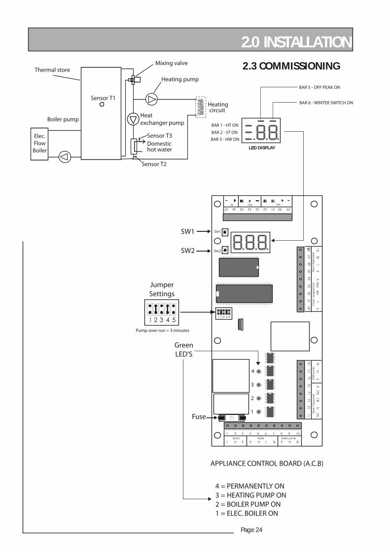
1
2
3
4
APPLIANCE CONTROL BOARD (A.C.B)
4 = PERMANENTLY ON3 = HEATING PUMP ON2 = BOILER PUMP ON1 = ELEC. BOILER ON
GreenLED'S
Fuse
JumperSettings
SW1
SW2 8
LED DISPLAY
BAR 1 - HT ON
BAR 2 - ST ON
BAR 3 - HW ON
BAR 5 - OFF PEAK ON
BAR 6 - WINTER SWITCH ON
Pump over-run = 3 minutes
Heating
Heating pump
circuit
Sensor T1
Domestichot water
Mixing valve
Heatexchanger pump
Sensor T3
Sensor T2
Thermal store
Boiler pump
Elec.FlowBoiler
Page 25
ELEC
TRA
MAT
E 20
00
2.0 INSTALLATION2.3 COMMISSIONING
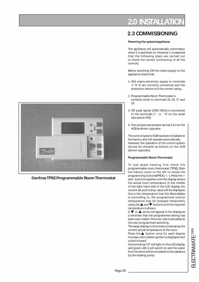
Danfoss TP5E Programmable Room Thermostat
Powering the system/appliance
The appliance will automatically commission when it is switched on. However it is essential that the following steps are carried out to check the correct functioning of all the controls.
Before switching ON the mains supply to the appliance check that :
1. 45A mains electricity supply to terminals ‘L’ ‘N’ ‘E’ are correctly connected and the protection device is of the correct rating.
2. Programmable Room Thermostat is correctly wired to terminals 25, 26, 27 and 28.
3. Off peak signal (230V 50Hz) is connected to the terminals ‘L’ ‘ ‘ ‘N’ on the small tele-switch PCB.
4. Two jumpers are present across 2 & 4 on the ACB as shown opposite.
The control system/ACB has been initialised at the factory and will operate automatically.However, the operation of the control system should be checked as follows on the ACB (shown opposite).
Programmable Room Thermostat
To test space heating f irst check the programmable room thermostat (TP5E). Slide the battery cover to the left to reveal the programming buttons(PROG, +, -). Press the + and - buttons together until the display shows the actual room temperature. In the middle of the right hand side of the LCD display the current set point temp. value will be displayed, this is the temperature that the ElectraMate is controlling to. The programmed control temperature may be changed temporarily using the and buttons until the required temperature is shown.A or arrow will appear in the display as a reminder that the programmed setting has been over-ridden. This over-ride is cancelled at the next programmed switching.The large display in this mode is indicating the current actual temperature of the room.Press the button once for each degree increase until a flame symbol is displayed and a click is heard. Horizontal bar ‘HT’ will light on the LCD display and green LED-3 will switch on and the water from the store will be circulated to the radiators by the heating pump.
Page 26
2.0 INSTALLATION2.3 COMMISSIONING
Switch off space heating from the programmer or room thermostat.Horizontal bar on the LCD screen ‘HT’ will switch off and green LED-3 will switch off.The heating pump will stop circulating water to the radiator circuit.
1. Move the Summer/Winter switch. Horizontal bar ‘2’(above the ‘n’) will light on the LCD display when the switch
is in the winter position.
2. Check operation of ‘on-peak/off-peak’ detection by switching the main signal to PCB.
When ‘off-peak’ signal is present, the horizontal bar ‘1’ (above the ‘0’) on the LCD display will light.
3. Turn the hot water tap on and off. When the hot water tap is opened the horizontal bar ‘DHW’ will light when the hot water is running.
Note : The heating pump will automatically be switched off when hot water is being drawn.
4. When the store is charging the green LED’s 1 and 2 on the pcb will be lit. When the store has finished charging, the green LED 1 will switch off and after 3
minutes the green LED 2 will switch off.
The ElectraMate 2000 has a SUMMER/WINTER switch.During the months when heating is not required, switch to summer mode. This is an energy saving function and the unit will continue to provide hot water on demand.
To keep the cupboard temperature to a minimum in summer it is recommended that any exposed hot water/heating pipework in the cupboard is insulated.
A link is fitted between terminals 21 & 22 on the appliance control board. This allows the appliance to be charged automatically at any time under control of the store thermostat.
The internal controls automatically select the store charge temperature and control thermostat differential to suit the electricity tariff. The temperature settings established during commissioning can be checked using push button switches sw1 and sw2 on the PCB as described in Section 3.4 Fault Finding.
This product is covered by the ‘Benchmark’ scheme and a separate commissioning/service log book is included with this product. This must be completed during commissioning and left with the product to meet the warranty conditions offered by Gledhill.
On completion :
1. Do ensure that the electrical connections (e.g. mains supply, room thermostat) to the unit are correct and tight.
2. Do ensure that the functioning and control of the system including the programmable room thermostat is explained to the occupant.
3. DON’T place any clothing or other combustible materials against or on top of this appliance.
These Instructions should be placed along with the component manufacturers instructions in the pocket provided on the rear of the front panel. The front panel should then be refitted.
When the system has been commissioned and all the air released from the initial fill close the AAV cap.
Use as necessary in the future when carrying our any repairs/modifications to the system/appliance to ensure the appliance vessel is not damaged during draining down and then close again as the above.
Page 27
ELEC
TRA
MAT
E 20
00
3.0 SERVICING3.1 ANNUAL SERVICING
No annual servicing of the ElectraMate 2000 is necessary.However, we would recommend that checks on the appliance controls and a hot water performance test are carried out annually to prove the appliance is working satisfactorily and within its specification.
3.2 CHANGING/ COMPONENTS
This appliance has two independant electrical supplies. Ensure that both supplies are isolated before removing the front panel to undertake any work.
Free of charge replacements for any faulty components are available from Gledhill during the in-warranty period (normally 12 months).
After this, spares can be obtained direct from Gledhill using the ‘Speed Spares’ service, or through any of the larger plumbers merchants/specialist heating spares suppliers.
Help and advice is also available from the Technical Helpline on 08449 310000.
However, all components are readily accessible and can be changed quickly and easily by the installer using common plumbing practice.
If it is necessary to replace any of the pumps fitted to the appliance the pump head (motor pack) only should be removed as recommended by Grundfos. Assuming it is within warranty this will be accepted by a merchant as being covered by the Grundfos national service exchange agreement, as long as it is a complete pump i.e. alleged faulty motor pack and new base is left with the merchant. It is important when a pump has been replaced to ensure that any air is adequately vented.
If the heater bottles are being replaced it is important that the appliance is run without the elements being live to ensure any air is removed from the bottles and the elements are not dry fired. To ensure this occurs the heater bottle fuses should be removed and only replaced once you are sure any air has been removed.
WARNING : There are no user serviceable parts inside the appliance cover. All annual inspections and/or servicing must be carried out by suitably qualified and competent persons.

Page 28
3.0 SERVICING
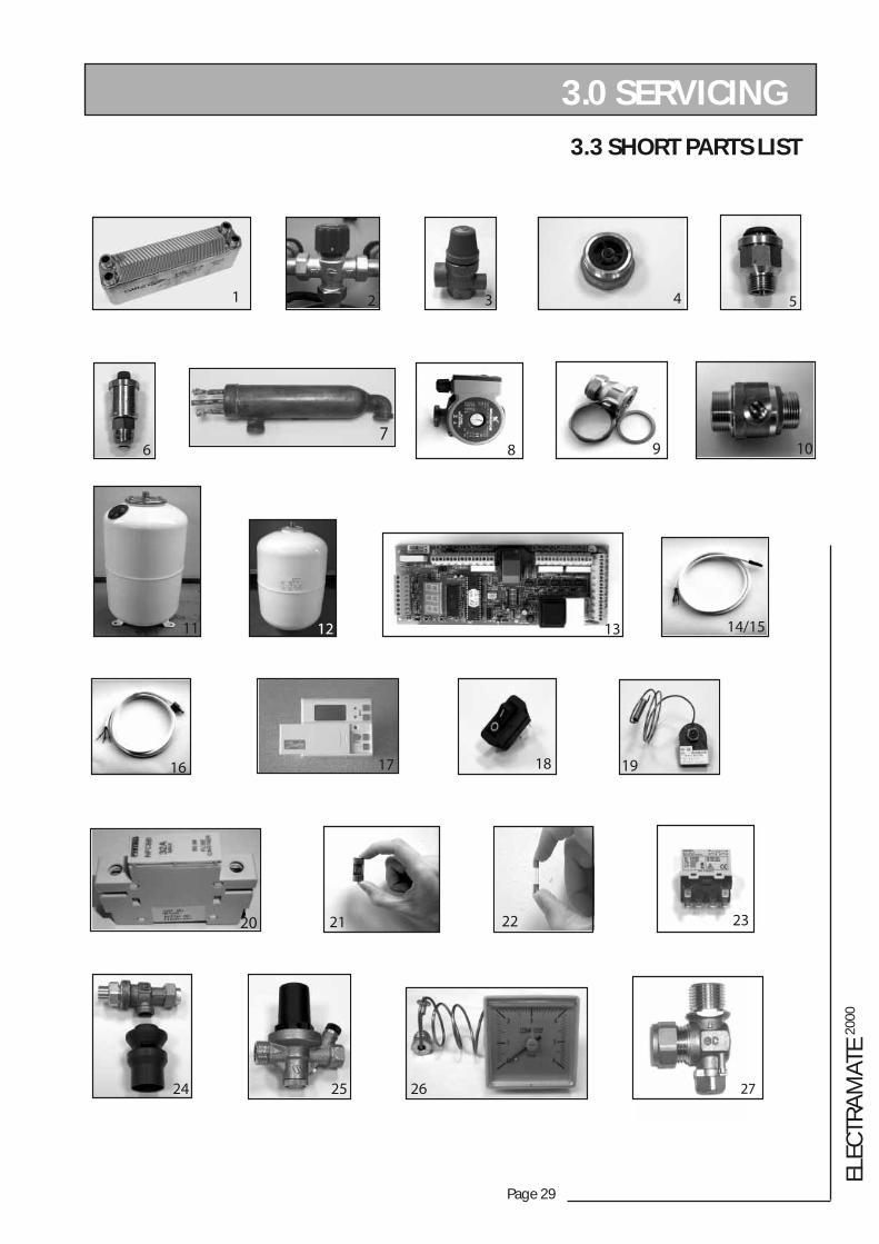
.oNyeK noitpircseD rerutcafunaM .oNedoCkcotS .oNtraPlicnuoCsaG
1 regnahcxetaehetalP pewS 710TG 46650E
2 evlavgniximtroP3 600CX 395-28E
3 evlavfeileR"2/1 591TG 87473E
4 evlavnruternoN .oCcitsalPliateD 840TG 974-73E
5 evlavmuucavitnA 650TG 97650E
6 tnevriacitamotuA"2/1 510TG 95720E
7 reliobwolfcirtceleWk9HCTIWS cetdraW 243BX
8 pmup05-51sofdnurG sofdnurG 400BX 882483
9 evlavpmupepytllaBmm22 ocmeV 121BX 01062E
01 evlavxif'O'llaBmm22 420TG 59952E
11 lessevnoisnapxEertil04 ecnaileR 403BX 75193E
21 lessevnoisnapxEertil52 ecnaileR 561GX
31 draoblortnocecnailppA kolE 551TG 85193E
41 rosnesnruterEHP kolE GT153 (Extended)
51 rosneserotS kolE 941TG 22062E
61 rosnesWHD kolE 351TG 42062E
71 tatS/TmooRelbammargorPE5PTssofnaD ssofnaD 563BX
81 hctiwsretniW/remmuS 430TG 87650E
91 )teserlaunam(tatsomrehTtaehrevOerotS/relioB 460TG 879793
02 esabesuf03CA suetorP 883BX
12 esufpmA52 463BX
22 pmA5esufkaerbhgihmm02 283BX 26193E
32 yalerrewoP 892BX 36193E
42 evlavnoitneverpwolfkcaBAC seirtsudnIsttaW 2/193BX
52 evlavgnicudererusserP seirtsudnIsttaW 093BX
62 eguagerusserpmetsysyramirP 971TG
72 evlavllaBelgnAº09 nocsaG 893BX
3.3 SHORT PARTS LIST
Page 29
ELEC
TRA
MAT
E 20
00
3.0 SERVICING
3.3 SHORT PARTS LIST
9 10
2 4
6 8
1
1311 14/15
16 18 19
232221
53
12
17
24 25 26 27
20
7
Page 30
3.0 SERVICING
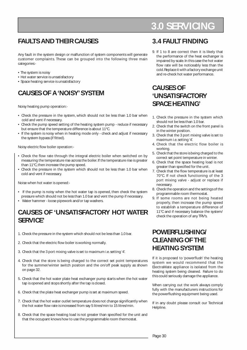
3.4 FAULT FINDINGFAULTS AND THEIR CAUSES
Any fault in the system design or malfunction of system components will generate customer complaints. These can be grouped into the following three main categories:-
• The system is noisy• Hot water service is unsatisfactory• Space heating service is unsatisfactory
CAUSES OF A ‘NOISY’ SYSTEM
Noisy heating pump operation:-
• Check the pressure in the system, which should not be less than 1.0 bar when cold and vent if necessary.• Check the pump speed setting of the heating system pump - reduce if necessary but ensure that the temperature difference is about 11°C.• If the system is noisy when in heating mode only - check and adjust if necessary the system bypass (if fitted).
Noisy electric flow boiler operation:-
• Check the flow rate through the integral electric boiler when switched on by measuring the temperature rise across the boiler. If the temperature rise is greater than 11°C, then increase the pump speed.• Check the pressure in the system which should not be less than 1.0 bar when cold and vent if necessary.
Noise when hot water is opened:-
• If the pump is noisy when the hot water tap is opened, then check the system pressure which should not be less than 1.0 bar and vent the pump if necessary.• Water hammer - loose pipework and/or tap washers.
CAUSES OF ‘UNSATISFACTORY HOT WATER SERVICE’
1. Check the pressure in the system which should not be less than 1.0 bar.
2. Check that the electric flow boiler is working normally.
3. Check that the 3 port mixing valve is set to maximum i.e. setting ‘4’.
4. Check that the store is being charged to the correct set point temperatures for the summer/winter switch position and the on/off peak supply as shown on page 32.
5. Check that the hot water plate heat exchanger pump starts when the hot water tap is opened and stops shortly after the tap is closed.
6. Check that the plate heat exchanger pump is set at maximum speed.
7. Check that the hot water outlet temperature does not change significantly when the hot water flow rate is increased from say 5 litres/min to 15 litres/min.
8. Check that the space heating load is not greater than specified for the unit and that the occupant knows how to use the programmable room thermostat.
CAUSES OF ‘UNSATISFACTORY SPACE HEATING’
1. Check the pressure in the system which should not be less than 1.0 bar.2. Check that the switch on the front panel is in the winter position.3. Check that the 3 port mixing valve is set to maximum i.e. setting ‘4’.4. Check that the electric flow boiler is working.5. Check that the store is being charged to the correct set point temperature in winter.6. Check that the space heating load is not greater than specified for the unit.7. Check that the flow temperature is at least 70°C. If not check functioning of the 3 port mixing valve - adjust or replace if necessary.8. Check the operation and the settings of the programmable room thermostat.9. If some rooms are not being heated properly, then increase the pump speed to establish a temperature difference of 11°C and if necessary balance the system/ check the operation of any TRV’s.
POWERFLUSHING/CLEANING OF THE HEATING SYSTEMIf it is proposed to ‘powerflush’ the heating system we would recommend that the ElectraMate appliance is isolated from the heating system being cleaned. Failure to do this could seriously damage the appliance.
When carrying out the work always comply fully with the manufacturers instructions for the powerflushing equipment being used.
If in any doubt please consult our Technical Helpline.
9. If 1 to 8 are correct then it is likely that the performance of the heat exchanger is impaired by scale. In this case the hot water flow rate will be noticeably less than the cold. Replace it with a factory exchange unit and re-check hot water performance.

Page 31
ELEC
TRA
MAT
E 20
00
3.0 SERVICING 3.4 FAULT FINDING
The operation of the ACB itself can be checked as follows :
• Switch off mains.• Check/insert correct jumpers i.e. across 2 and 4.• Insert jumper 5.• Switch on mains.• The PCB will carry out functional tests and then stop. LED’s 1-4 will be switched ON then OFF at 5 second intervals and the output number will be indicated on the LED display. When complete the LED display will be as follows : • Switch off mains.• Remove jumper 5.• Switch on mains to put into normal mode.
If there is any discharge from the Pressure Relief Safety Valve.
• Check that the system is not over-pressurised when cold - nominal charge pressure should be about 1.0 bar.• Check that the air pressure inside the expansion vessel is correct - refill with air if necessary to nominal value of 1.0 bar when the system is de-pressurised.• Check that the expansion vessel is correctly sized for the system volume.• Check the pressure relief valve seat - replace if necessary.
The boiler overheat thermostat will trip (pop-out) if :
• TheBoiler pump is faulty.• The control thermostat on PCB is faulty.• The System is air locked i.e poor circulation through electric boiler circuit.Check and replace faulty parts and manually push the reset button on the boiler overheat thermostat.
If the store overheat thermostat has activated or failed, it is important to check the boiler pump and store temperature sensor are working correctly. Remove the cap on the STORE o/heat t/stat, if this has popped out you must replace the BOILER o/heat t/stat. Press the reset button and replace the cap on the STORE o/heat t/stat. Check that the boiler pump is operating and that the pump switches off when the store temperature sensor is up to its operating temperatures - see page 32 for details.If the BOILER o/heat t/stat or the STORE o/heat t/stat continue to activate then please contact the manufacturers for advice.WARNING : UNDER NO CIRCUMSTANCES SHOULD THESE TWO SAFETY CONTROLS BE MANUALLY HELD DOWN OR TAKEN OUT OF CIRCUIT.
Page 32
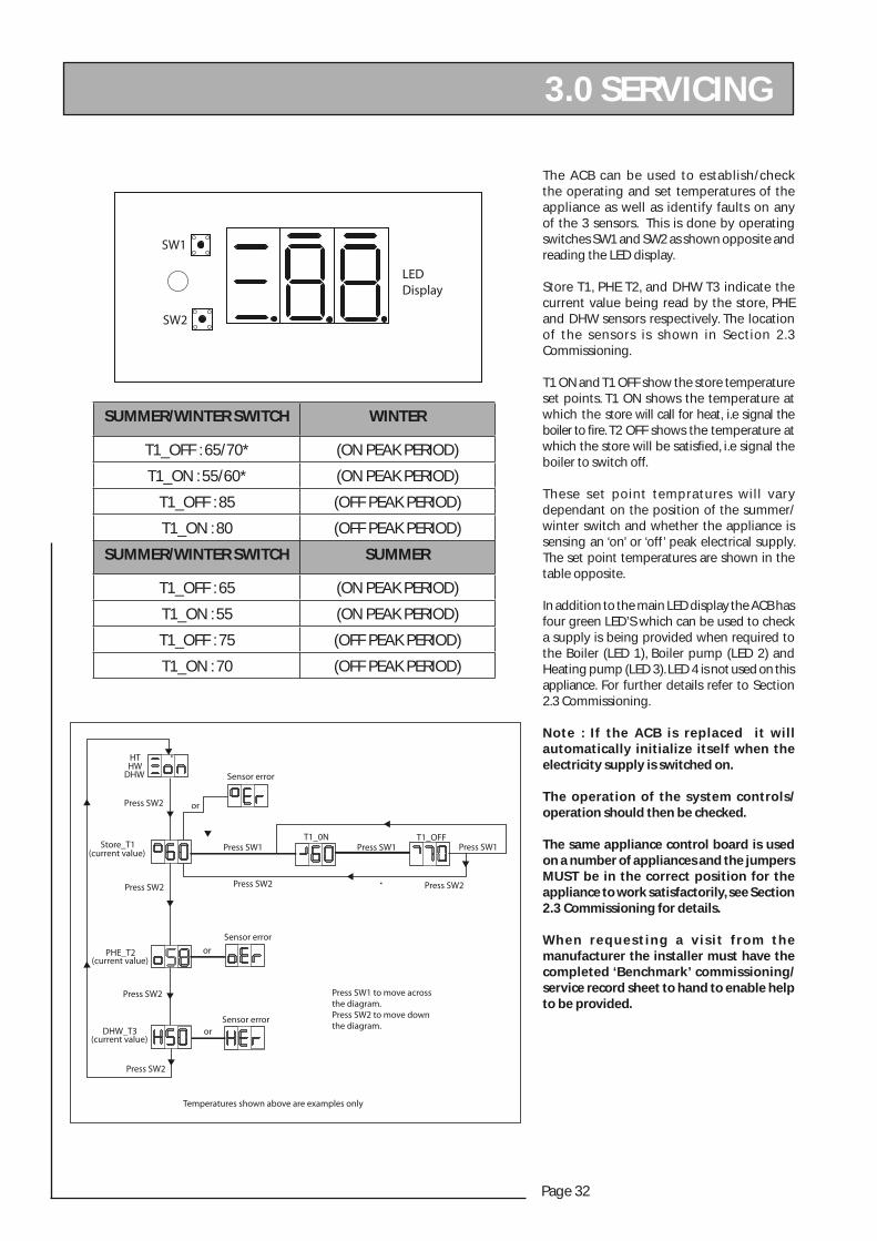
The ACB can be used to establish/check the operating and set temperatures of the appliance as well as identify faults on any of the 3 sensors. This is done by operating switches SW1 and SW2 as shown opposite and reading the LED display.
Store T1, PHE T2, and DHW T3 indicate the current value being read by the store, PHE and DHW sensors respectively. The location of the sensors is shown in Section 2.3 Commissioning.
T1 ON and T1 OFF show the store temperature set points. T1 ON shows the temperature at which the store will call for heat, i.e signal the boiler to fi re. T2 OFF shows the temperature at which the store will be satisfi ed, i.e signal the boiler to switch off.
These set point tempratures will vary dependant on the position of the summer/winter switch and whether the appliance is sensing an ‘on’ or ‘off’ peak electrical supply. The set point temperatures are shown in the table opposite.
In addition to the main LED display the ACB has four green LED’S which can be used to check a supply is being provided when required to the Boiler (LED 1), Boiler pump (LED 2) and Heating pump (LED 3). LED 4 is not used on this appliance. For further details refer to Section 2.3 Commissioning.
Note : If the ACB is replaced it will automatically initialize itself when the electricity supply is switched on.
The operation of the system controls/operation should then be checked.
The same appliance control board is used on a number of appliances and the jumpers MUST be in the correct position for the appliance to work satisfactorily, see Section 2.3 Commissioning for details.
W h e n r e q u e s t i n g a v i s i t f r o m t h e manufacturer the installer must have the completed ‘Benchmark’ commissioning/service record sheet to hand to enable help to be provided.
SW1
SW2
LEDDisplay
HTHW
DHW
Press SW2
Press SW2
Press SW2
Press SW1Press SW1
Press SW2 Press SW2
Press SW1Store_T1(current value)
PHE_T2(current value)
DHW_T3(current value)
or
or
or
Press SW2
Sensor error
Sensor error
Sensor error
T1_0N T1_OFF
Press SW1 to move acrossthe diagram.Press SW2 to move downthe diagram.
Temperatures shown above are examples only
3.0 SERVICING
SUMMER/WINTER SWITCH WINTER
T1_OFF : 65/70* (ON PEAK PERIOD)
T1_ON : 55/60* (ON PEAK PERIOD)
T1_OFF : 85 (OFF PEAK PERIOD)
T1_ON : 80 (OFF PEAK PERIOD)
SUMMER/WINTER SWITCH SUMMER
T1_OFF : 65 (ON PEAK PERIOD)
T1_ON : 55 (ON PEAK PERIOD)
T1_OFF : 75 (OFF PEAK PERIOD)
T1_ON : 70 (OFF PEAK PERIOD)
Page 33
ELEC
TRA
MAT
E 20
00
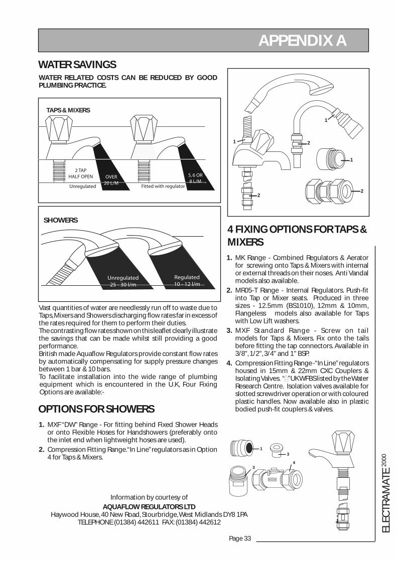
WATER RELATED COSTS CAN BE REDUCED BY GOOD PLUMBING PRACTICE.
Vast quantities of water are needlessly run off to waste due to Taps, Mixers and Showers discharging fl ow rates far in excess of the rates required for them to perform their duties.The contrasting fl ow rates shown on this leafl et clearly illustrate the savings that can be made whilst still providing a good performance. British made Aquafl ow Regulators provide constant fl ow rates by automatically compensating for supply pressure changes between 1 bar & 10 bars.To facilitate installation into the wide range of plumbing equipment which is encountered in the U.K, Four Fixing Options are available:-
1. MXF “DW” Range - For fi tting behind Fixed Shower Heads or onto Flexible Hoses for Handshowers (preferably onto the inlet end when lightweight hoses are used).
2. Compression Fitting Range. “In Line” regulators as in Option 4 for Taps & Mixers.
APPENDIX A
34
31
2
22
1
1
1
Unregulated25 - 30 l/m
Regulated10 - 12 l/m
SHOWERS
WATER SAVINGS
OPTIONS FOR SHOWERS
4 FIXING OPTIONS FOR TAPS & MIXERS1. MK Range - Combined Regulators & Aerator for screwing onto Taps & Mixers with internal or external threads on their noses. Anti Vandal models also available.
2. MR05-T Range - Internal Regulators. Push-fi t into Tap or Mixer seats. Produced in three sizes - 12.5mm (BS1010), 12mm & 10mm, Flangeless models also available for Taps with Low Lift washers.
3. MXF Standard Range - Screw on tail models for Taps & Mixers. Fix onto the tails before fi tting the tap connectors. Available in 3/8", 1/2", 3/4" and 1" BSP.
4. Compression Fitting Range - “In Line” regulators housed in 15mm & 22mm CXC Couplers & Isolating Valves. “ ”UK WFBS listed by the Water Research Centre. Isolation valves available for slotted screwdriver operation or with coloured plastic handles. Now available also in plastic bodied push-fi t couplers & valves.
Information by courtesy of
AQUAFLOW REGULATORS LTDHaywood House, 40 New Road, Stourbridge, West Midlands DY8 1PA
TELEPHONE (01384) 442611 FAX: (01384) 442612
TAPS & MIXERS
OVER20 L/M
5, 6 OR8 L/M
2 TAPHALF OPEN
Fitted with regulatorUnregulated
Page 34
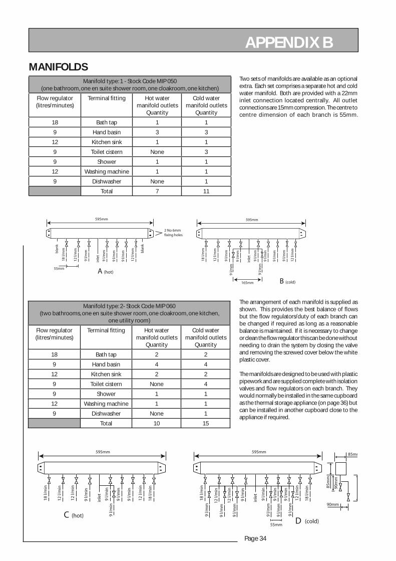
APPENDIX B
Two sets of manifolds are available as an optional extra. Each set comprises a separate hot and cold water manifold. Both are provided with a 22mm inlet connection located centrally. All outlet connections are 15mm compression. The centre to centre dimension of each branch is 55mm.
The arrangement of each manifold is supplied as shown. This provides the best balance of fl ows but the fl ow regulators/duty of each branch can be changed if required as long as a reasonable balance is maintained. If it is necessary to change or clean the fl ow regulator this can be done without needing to drain the system by closing the valve and removing the screwed cover below the white plastic cover.
The manifolds are designed to be used with plastic pipework and are supplied complete with isolation valves and fl ow regulators on each branch. They would normally be installed in the same cupboard as the thermal storage appliance (on page 36) but can be installed in another cupboard close to the appliance if required.
595mm
2 No 6mmfixing holes
18 l/
mm
12 l/
mm
9 l/
mm
9 l/
mm
9 l/
mm
9 l/
mm
12 l/
mm
inle
t
55mm
18 l/
mm
12 l/
mm
9 l/
mm
9 l/
mm
9 l/
mm
9 l/
mm
9 l/
mm
9 l/
mm
9 l/
mm
9 l/
mm
12 l/
mm
inle
t
165mm
595mm
A (hot)
B (cold)
bla
nk
bla
nk
18 l/
min
12 l/
min
12 l/
min
9 l/
min
9 l/
min
9 l/
min
9 l/
min
9 l/
min
12 l/
min
18 l/
min
inle
t
595mm
CD
18 l/
min
12 l/
min
12 l/
min
9 l/
mm
9 l/
mm
9 l/
mm
9 l/
mm
9 l/
mm
9 l/
mm
9 l/
min
9 l/
min
9 l/
min
9 l/
min
12 l/
min
18 l/
min
inle
t
55mm
595mm
90mm
85mm
85m
m
90m
m
(hot)(cold)
MANIFOLDS Manifold type: 1 - Stock Code MIP 050
(one bathroom, one en suite shower room, one cloakroom, one kitchen)
Flow regulator(litres/minutes)
Terminal fi tting Hot water manifold outlets
Quantity
Cold water manifold outlets
Quantity
18 Bath tap 1 1
9 Hand basin 3 3
12 Kitchen sink 1 1
9 Toilet cistern None 3
9 Shower 1 1
12 Washing machine 1 1
9 Dishwasher None 1
Total 7 11
Manifold type: 2- Stock Code MIP 060(two bathrooms, one en suite shower room, one cloakroom, one kitchen,
one utility room)
Flow regulator(litres/minutes)
Terminal fi tting Hot water manifold outlets
Quantity
Cold water manifold outlets
Quantity
18 Bath tap 2 2
9 Hand basin 4 4
12 Kitchen sink 2 2
9 Toilet cistern None 4
9 Shower 1 1
12 Washing machine 1 1
9 Dishwasher None 1
Total 10 15

Page 35
ELEC
TRA
MAT
E 20
00
APPENDIX BThe pressure loss through a fl ow regulator at the designated fl ow rate is about 1.8 bar. Therefore for the fl ow regulator to control the fl ow rate at pre-set level, the inlet pressure must be greater than 1.8 bar. If the inlet pressure is lower, the fl ow rate will be correspondingly less than the pre-set values.
The maximum equivalent pipe lengths from the manifold to the terminal fi ttings can be estimated from the above information and the resistance characteristics of the pipes. The examples presented below are for 15mm copper pipe in table 1 and for plastic pipework in table 2.
The preferred solution where space will allow
An optional location where cupboard space is tight
Table 1: Maximum equivalent pipe length in 15mm copper
Inlet pressure (bar)
Maximum equivalent length of pipe (m)
@ 9 l/m @ 12 l/m @ 18 l/m
2.0 25 10 5
2.5 75 30 15
3.0 150 60 30
Table 2: Maximum equivalent pipe length in plastic pipe
Inlet pressure (bar)
Maximum equivalent length of pipe (m)
@ 9 l/m @ 12 l/m @ 18 l/m
2.0 1.5 15mm : 10 15mm : 4.522mm : 40
2.5 3.0 15mm : 20 15mm : 9.022mm : 80.0
3.0 4.5 15mm : 30 15mm 13.522mm : 120
Page 36
APPENDIX B
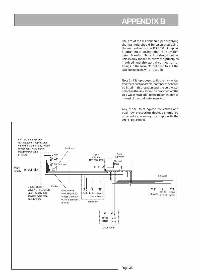
The size of the distribution pipes supplying the manifold should be calculated using the method set out in BS 6700. A typical diagrammatic arrangement of a system using Manifold Type 1 is shown below. This is only meant to show the principles involved and the actual connection of fi ttings to the manifold will need to suit the arrangements shown on page 35.
Note 1 - If it is proposed to fi t chemical water treatment such as a water softener this should be fi tted in this location and the cold water branch in the sink should be branched off the cold water main prior to the treatment device instead of the cold water manifold.
Any other isolating/control valves and backflow protection devices should be provided as necessary to comply with the Water Regulations.
Bath Toiletcistern
Handbasin
Toiletcistern
Handbasin
Handbasin
Toiletcistern
Mainssupply
Shower
DW
Kitchen sink
Kitchen
En-Suite
Bathroom
Check valveNOT REQUIREDunless chemicalwater treatmentis fitted
Double check valve NOT REQUIREDunless supply pipeservices more thanone dwelling
Pressure limiting valveNOT REQUIRED at pressuresbelow 5 bar unless any systemcomponents have a lowermaximum workingpressure
Cloak room
WMThermal Store
Scale inhibitor
NOT REQUIRED
Airingcupboard
See Note 1
Page 37
ELEC
TRA
MAT
E 20
00
APPENDIX C
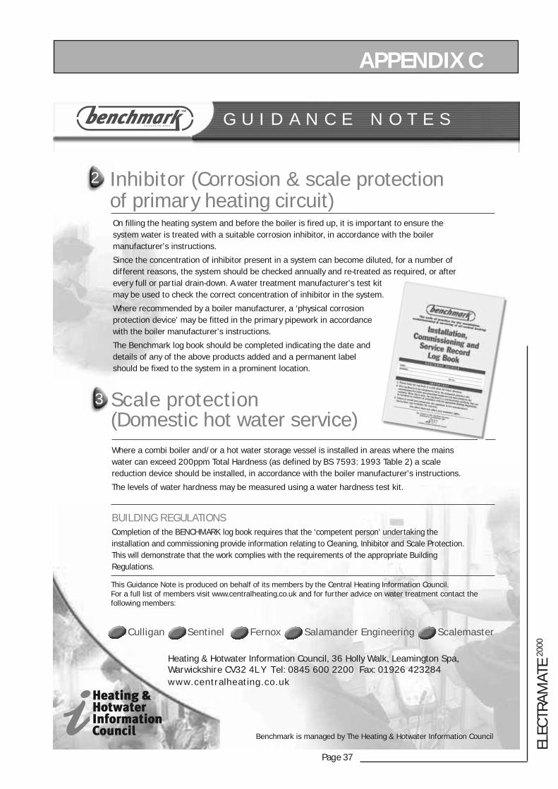
2 Inhibitor (Corrosion & scale protectionof primary heating circuit)
G U I D A N C E N O T E S
3 Scale protection(Domestic hot water service)
On filling the heating system and before the boiler is fired up, it is important to ensure thesystem water is treated with a suitable corrosion inhibitor, in accordance with the boilermanufacturer’s instructions.
Since the concentration of inhibitor present in a system can become diluted, for a number ofdifferent reasons, the system should be checked annually and re-treated as required, or afterevery full or partial drain-down. A water treatment manufacturer’s test kitmay be used to check the correct concentration of inhibitor in the system.
Where recommended by a boiler manufacturer, a ‘physical corrosionprotection device’ may be fitted in the primary pipework in accordancewith the boiler manufacturer’s instructions.
The Benchmark log book should be completed indicating the date anddetails of any of the above products added and a permanent labelshould be fixed to the system in a prominent location.
Where a combi boiler and/or a hot water storage vessel is installed in areas where the mainswater can exceed 200ppm Total Hardness (as defined by BS 7593: 1993 Table 2) a scalereduction device should be installed, in accordance with the boiler manufacturer’s instructions.
The levels of water hardness may be measured using a water hardness test kit.
BUILDING REGULATIONSCompletion of the BENCHMARK log book requires that the ‘competent person’ undertaking theinstallation and commissioning provide information relating to Cleaning, Inhibitor and Scale Protection.This will demonstrate that the work complies with the requirements of the appropriate BuildingRegulations.
This Guidance Note is produced on behalf of its members by the Central Heating Information Council. For a full list of members visit www.centralheating.co.uk and for further advice on water treatment contact thefollowing members:
Culligan Sentinel Fernox Salamander Engineering Scalemaster
Heating & Hotwater Information Council, 36 Holly Walk, Leamington Spa,Warwickshire CV32 4L Y Tel: 0845 600 2200 Fax: 01926 423284www.centralheating.co.uk
Benchmark is managed by The Heating & Hotwater Information Council
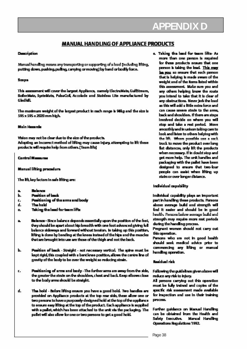
Page 38
APPENDIX D
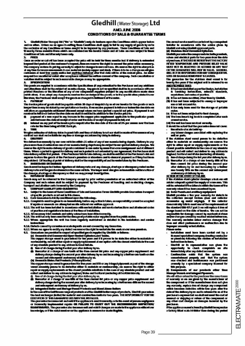
Page 39
ELEC
TRA
MAT
E 20
00
Page 40