Embed Size (px)
Citation preview

ELECTRIC CHAIN HOIST
DMK SERIES

2
DMK SERIES, THE MOST RELIABLE AND SAFE WAY TO LIFT LOADS UP TO 4.000 kg
The DMK series electric chain hoists meet the needs of the international market which requires products featuring guaranteed quality, a wide range of uses, long-term reliability, safety guarantees during all operating phases and excellent value for money. DMK hoists are known for the quality of their components, high technology used to machine mechanical parts, finishing and surface treatments, constant and controlled quality system certified EN ISO 9001 which covers all company activities, and makes it possible for DONATI SOLLEVAMENTI to offer a product in line with the latest international standards. The special water-repellent paintwork, applied with a completely enclosed electrostatic process, guarantees durability and constant top performance, including in particularly hostile environments. DMK series electric chain hoists are part of the lifting products range manufactured by DONATI SOLLEVAMENTI, a leading company in this field in Italy and part of the Terex Group, one of the biggest company’s in the lifting sector on a worldwide level.
ELECTRIC CHAIN HOIST

3
AND TROLLEYS
POWERFUL AND SAFE TROLLEYS AT YOUR SERVICE
The electric chain hoist is a machine generally used to lift un-guided loads, using a hook or handling accessories adequate for the purpose.When the hoist is combined with an electric or manual trolley, which run on a beam, it ensures combined lifting and horizontal movement of the load.The electric chain hoist and trolleys can be mounted overhead and fitted with monorails or act as the lifting unit for other machines where they have been incorporated, including: jib crane, bridge crane, etc.The electric chain hoist, positioned overhead or on the ground, can also be used in various fixed position configurations.

4
DMK series electric chain hoists and electric trolleys are manufactured based on a modular component design, assembled together based on commercial needs and make it possible to quickly and inexpensively create many standardised and special executions. Standard versions are always available at our warehouse.Thanks to the extreme compactness of the basic components, i.e. the motor and gearbox, they are assembled together in a coaxial line, in order to ensure the maximum use of the hook run and minimum encumbrance of the hoist.The construction uses the most advanced technologies based on high industrialisation production processes and makes it possible to create completely reliable and technically innovative machines through economies of scale.The high quality level is guaranteed and controlled by the company quality system certified according to the standard EN ISO9001: 2008.

5
THE DMK SERIES ELECTRIC CHAIN HOIST RANGE IS CREATED IN:
4 basic sizes: for loads from 100 to 4,000 kg, in FEM (ISO) service units 1Bm (M3) - 1Am (M4) - 2m (M5).
One lifting speed created with 1 polarity motor: 4 or 6,3; 8; 16 m/min. for 1 chain fall hoists 3,2 or 4m/min. for 2 chain fall hoists
Two lifting speeds created with pole changing motor: 4/1,2 or 6,3/2.1; 8/2,5 m/min. for 1 chain fall hoists 2,5/0,8 or 3,2/1 m/min. for 2 chain fall hoists
Standard hook run: up to 12 m over 12 m upon request
PROTECTION AND INSULATION OF ELECTRICAL PARTS Self-braking In the lifting and travelling motors;
IP55 protection – “F” insulation class
DMK 2-3-4 brake: IP23
Limit switch: IP65 minimum protection – 500 V maximum insulation voltage
Cables: IEC 20/22 II 450/750 V maximum insulation voltage
Non-standard protections and insulations are available upon request.
ELECTRICAL POWER SUPPLY Standard DMK electric chain hoists are designed to be
powered with AC current with the following voltage: - three phase of 400 V - 50Hz. according to IEC 38-1 - single phase of 230 V +/- 5% - 50 Hz. (for DMK 1-2-3 hoists at one speed and capacity up to 800 kg)
Non-standard voltages and frequencies are available upon request.
NOMINAL USE CONDITIONS IN THE STANDARD EXECUTION: Operating temperature: minimum -10°C; maximum +40°C
Maximum relative humidity: 80%
Maximum altitude 1000 m above sea level
The machine must be installed indoors, in a well-ventilated place, free from corrosive fumes (acid fumes, saline mist, etc.)
NOISE LEVEL The sound pressure level emitted by the hoist when fully loaded
is always less than 85 dB (A). The incidence of environmental characteristics such as the transmission of sound through metallic structures, reflection caused by combined machines and walls, is not included in the indicated level.
FIXED EXECUTION: eyebolt suspension or hook suspension (upon request).
TROLLEY EXECUTION:HAND-PUSHED: horizontal movement by manually pushing the load.CHAIN: horizontal movement by chain controlled by the operator who controls the trolley wheels.ELECTRIC: movement is motorised (one or two speeds) and controlled directly from the hoist push button panel.
LOW HEADROOM EXECUTION: to use the maximum hook run, the hoist is fitted with a chain return system mounted on the trolley (electric or hand-push) with compact dimensions.
CLIMBING EXECUTION: the climbing execution makes it possible to reach the installation point with just the hook and chain, without having to lift the entire weight of the hoist. It is particularly suitable for the entertainment industry, or when frequent hoist assembly/disassembly operations are required at a greater height.

6
7
3
9
6
2
2
413
10
1
5
11
6
8
3
5
9
14 1
4
13
12
THE HOIST IN DETAILDESIGN AND CONSTRUCTION
1 CHAIN FALL UP TO 2000 KGThis is a winning technical solution that offers: more compact design and greater hook run since the bottom
block has smaller dimensions compared to a hook block and the chain box is smaller
greater safety for the operator who can touch the hook and chain without the risk of being dragged in and crushed
greater reliability, less maintenance and lower operating costs since jamming cannot occur, the chain is not worn by the return and there are no moving parts to replace in the bottom block
greater use flexibility
2 CHAIN FALLS OVER 2000 KGThis solution is aimed at the affordability of the entire system which: offers a fixed anchoring point on which to apply a sensitive load
limiter that is suitable for heavy-duty applications and does not require useless overdimensioning of the weight-bearing structure
limits the dimensions and cost of the chain
7
1. GEARBOXEpicyclic reduction gear with thermally treated, high resistance steel wheels, supported on ball bearings and lubricated in oil bath. The frame is a radiating fin structure in aluminium alloy to improve heat dissipation.
2. SELF-BRAKING ELECTRIC MOTORThe axial movement of the conical brake allows fast, reliable mechanical braking over time [RES. 4.1.2.6. c - Annex I Machinery Directive]. The brake lining is asbestos free. Asynchronous three phase with single polarity for one speed hoists, with pole changing version for two speed hoists.
3. CHAINThe chain is gauged and made of high-strength steel rod with excellent dynamic stability, ultimate tensile strength of 80 kg/mm2
and ultimate elongation no higher than 10%. The applicable safety coefficient is always greater than 5 [RES. 4.1.2.4. - Annex I Machinery Directive]. The heat and galvanising treatments applied to the chain provide high resistance to wear, aging and corrosion.
4. LOAD SPROCKETThe load sprocket is heat treated and has five pockets mechanically machined on high precision automatic machinery. The sprocket drives the chain, ensuring perfect chain movement.
5. CHAIN GUIDE (INSERTER/EXTRACTOR)The chain guide is used to insert and extract the chain links both in and out of the pockets, both when lifting and lowering [RES. 4.1.2.4. Annex I Machinery Directive].
6. LOAD HOOKThe hook is made from high strength steel and is equipped with a safety device (spring catch) to prevent the load from unhooking [RES. 4.1.2.6. e - Annex 1 Machinery Directive] and rotates on a thrust bearing.
7. BOTTOM BLOCK (ONE CHAIN FALL HOISTS)This connects the chain to the turning hook. It is made of steel and is equipped with a heat-treated large cross-section pin to lock the chain.
8. HOOK BLOCK (TWO CHAIN FALL HOISTS)Made of cast aluminium, completely closed, it is fitted with a high-resistance steel transmission reel that is thermally treated and has pockets for housing the chain.
9. CHAIN STOPSThe stops are installed on the free descending and ascending sections of the chain on one fall hoists. They act as limit switches for hoist travel [RES. 4.1.2.6.a - Annex I Machinery Directive]; they are made of forged steel and are fitted with a shock-absorbing insert.
CHAIN BOXThe chain box is used to hold the descending section of the chain. It is available in different sizes based on the hook travel. It is made of shock-resistant plastic and is equipped with suspensions to allow free movement.
10. CLUTCH DEVICE (ONE CHAIN FALL HOISTS)This is an emergency device, an up and down limit switch. It also acts as an overload protection [RES. 4.2.1.4. Annex I Machinery Directive]. The clutch discs are asbestos free and are preloaded with a Belleville washer system.
11. BALANCER (ONE CHAIN FALL HOISTS)The balancer is connected to the clutch device and ensures hoist balancing. It absorbs the heat generated during clutch movement.
12. DMK 2-3-4 BRAKEThe brake shoe installed on sizes 2-3 and 4 is made with a fan which ensures cooling of the brake and the motor. The high degree of inclination of the braking surface allows perfect unlocking of the brake even in the most difficult working conditions. Brake adjustment is easily performed since it can be done from the outside using the adjusting ring.
13. OVERLOAD DEVICE (TWO CHAIN FALL HOISTS) Electromechanical with a microswitch for one intervention threshold [RES. 4.2.1.4 - Annex I Machinery Directive]. The overload device does not allow the hoist to be loaded with an overload exceeding 20% of its maximum capacity, by blocking the lifting control circuit.
LIFTING LIMIT SWITCHES Standard equipment for 2 chain fall hoists and available upon request for 1 chain fall hoists. They limit the hook’s ascent and descent runs [RES. 4.1.2.6 a) Annex I Machinery Directive]. They are composed of two precision microswitches which function according to the “slow positive opening” principle and work on the auxiliary circuit of the lifting motor control device.
14. SUSPENSIONIt is produced with an eyebolt fitting; it can be made with a hook execution upon request or even a 90° eyebolt version for longitudinal hoist.
ELECTRICAL CONTROLSWhen the hoist is supplied with electrical control, the movements can be activated, alternatively, by: low voltage controls at AC 48V - 50Hz, including: the
transformer for the low voltage power supply of the control circuits, the general line contactor, the contactors for the control of the hoist and electric trolley motors, transformer protection fuses and terminal block for connections of the auxiliary and power circuits. The components are contained in a sealed box with IP 55 protection, made of shockproof thermoplastic material. The equipment is installed on the motor side of the hoist.
direct control, direct control, with mains voltage, solely available for the control of the electric hoist, for raise and lower functions. It is composed by a pushbutton panel that interrupts and directly switches the power line.
In both options, the controls are activated by the hanging pushbutton panel, with ergonomic shape, made of self-extinguishing, shockproof, waterproof, thermoplastic material, with IP 65 protection. The emergency stop function [RES. 1.2.4 - Annex I Machinery Directive], is produced with a mushroom-head button which, using an intentional release action, puts the control circuit in forward position [RES. 1.2.3 Annex I Machinery Directive].The hanging push button panel is connected to the hoist by a multipolar electrical cable supported by tear proof metallic parts.
DMT TROLLEYS used to horizontally move the load. They are manufactured in three difference versions: SM type, hand-pushed; CM type, mechanically-operated chain and EM type, electrically-operated. They move on the lower flange of the beam and can be adjusted based on the flange width. They are made of pressed steel plate (GR 2) and in pantographed sheet (GR3, 4 and 5) have anti-derail brackets [RES. 4.1.2.2. Annex I Machinery Directive] and shock-absorbing buffers. The trolleys are equipped with pressed steel machined wheels rotating on permanently lubricated ball bearings. Gear motor with self-braking motor: provides motion to the trolleytoothed wheels in the electric version, EM type [RES. 4.1.2.6. c - Annex I Machinery Directive].Limit switch: these switches limit horizontal travel of the electric trolley on the beam [RES. 4.1.2.6. a – Annex I Machinery Directive]. Towing arm: the towing arm, which connects the trolley to the power supply, is available for all types of trolleys of the DMT series. It can be easily adjusted in all directions and is an essential part for towing the power cable without tearing the conductors.

8
STANDARDS AND CERTIFICATIONSDESIGN AND CONSTRUCTION
DMK electric chain hoists and their trolleys are
designed and manufactured according to the
“Essential Safety Requirements” of Annex I of the
Machinery Directive 2006/42/EC and are placed
on the market equipped with CE Mark and
EC Declaration of Conformity - Annex II A.
In addition DMK electric chain hoists and their
trolleys are in compliance with the following
Directives:
LOW VOLTAGE DIRECTIVE 2006/95/EC
ELECTROMAGNETIC COMPATIBILITY DIRECTIVE 2004/108/EC
DMK series electric chain hoists and their trolleys
are also available with CSA homologation, upon
request.
REFERENCE NORMATIVE FRAMEWORKThe design and construction of DMK series electric chain hoists and their trolleys comply with the following technical standards and rules:
EN ISO 1210:2010 “Fundamental concepts, general design principles”
EN ISO 13849-1:2008 “Safety-related parts of control systems (where required)”
EN 12077-2:2008 “Limiting and indicating devices”
EN 60204-32:2009 “Safety of the electrical equipment of lifting machines”
• EN 60529:1997 “IP enclosure (IP Codes)”
• ISO 4301-1:1988 “Classification of lifting equipment”
• DIN 15401 “Choice of lifting hooks
• FEM 1.001/98 “Rules for the design of lifting equipment”
• FEM 9.511/86 “Mechanisms classification”
• FEM 9.671/88 “Quality of chains“
• FEM 9.683/95 “Choice of lifting and traverse motors”
• FEM 9.755/93 “Periods of safe work”
• FEM 9.941/95 “Control symbols“

9
CRITERIA OF USE AND OPERATING LIMITS
It is necessary to check the parameters which characterise the operating limits of the DMK electric chain hoists to be able to have a complete correspondence between the DMK electric chain hoists and the service they were designed for.These operating limits include the actual lifting capacity, state of stress and average duration of daily operation.
ACTUAL LIFTING CAPACITYThis is determined by the heaviest load to be lifted
! The nominal lifting capacity of the hoist must be >− the actual lifting capacity. Lifting capacity = kg
THE STATE OF STRESSThe state of stress is evaluated considering the actual entity of the loads to be lifted and it is ascribable to one of four spectrums of load shown below which determine the type of service.
AVERAGE DURATION OF DAILY OPERATIONFor LIFTING operations the average duration of operation is calculat-ed as follows:
Tm (hours) = (AHR x C/h x Rt) / (30 x S)
Actual hook runAHR = m
It is the average of the actual runs of the load
runn
ing h
ook
ascent pause
cycle (max. 10 min)
pausetime
descent
Cycles in an hourC/h = N°
It is the number of complete ascents and descents carried out in an hour.
Running timeRT = hours
Hoist running time in a whole day.
Lifting speedS = m/min
It is the distance covered by the load in a minute.
1) Light
Load
(%)
time (%)
Hoists which rarely lift maximum loads but
mainly reduced loads
3) Heavy
Load
(%)
time (%)
Hoists which frequently lift the maximum load but
normally medium loads.
2) Medium
Load
(%)
time (%)
Hoists which lift approximately the same number of maximum,
medium and reduced loads.
4) Very heavy
Load
(%)
time (%)
Hoists which regularly lift loads approximately
equal to the maximum load.
Operating limits of DMK hoists in relation to the service groups of the mechanisms, according to FEM 9.511/86 (ISO 4301-1:1988)
Group FEM (ISO)
Average duration of daily operation - Tm = Hours; with load Intermittence ratio % N° of starts per hour N° of cycles per hour
1) Light 2) Medium 3) Heavy 4) Very heavy
1 Bm (M 3) 2 1 0.5 0.25 RI = 25% A/h = 150 C/h = 251 Am (M 4) 4 2 1 0.5 RI = 30% A/h = 180 C/h = 302 m (M 5) 8 4 2 1 RI = 40% A/h = 240 C/h = 40

10
TECHNICAL SPECIFICATIONS AND DATA FORDMK CHAIN HOISTS WITH DMT TROLLEYS
Characteristic data for DMK series electric chain hoists and DMT trolleys
Capacity (kg)
FEM group
DMK type
Chain falls
Lifting speed
(m/min)
Lifting motor power
(kW)
DMT trolley type for hoistS= manual-push trolley C= manual gear operated trolley E=electric trolley
Trolley motor power (kW)
Chain type
Chain weight
per meter(Kg/m)
ESpeed (m/min) Speed (m/min)
1 Speed 2 Speed 1 Speed 2 Speed S C 11 14 22 7/22 11 14 22 7/22
125
2m 154C 1 8 / 0.2 / SM2 CM3 EM3 EM3 EM3 EM3 0.12 0.18 0.25 0.08 0.25 4X12 0.38
2m 132D 1 8 2.5 0.2 0.06 SM2 CM3 EM3 EM3 EM3 EM3 0.12 0.18 0.25 0.08 0.25 4X12 0.38
2m 232C 1 16 / 0.4 / SM2 CM3 EM3 EM3 EM3 EM3 0.12 0.18 0.25 0.08 0.25 5X15 0.58
250
2m 134C 1 4 / 0.2 / SM2 CM3 EM3 EM3 EM3 EM3 0.12 0.18 0.25 0.08 0.25 4X12 0.38
2m 112D 1 4 1.2 0.2 0.06 SM2 CM3 EM3 EM3 EM3 EM3 0.12 0.18 0.25 0.08 0.25 4X12 0.38
2m 234C 1 8 / 0.4 / SM2 CM3 EM3 EM3 EM3 EM3 0.12 0.18 0.25 0.08 0.25 5X15 0.58
2m 234D 1 8 2.5 0.4 0.12 SM2 CM3 EM3 EM3 EM3 EM3 0.12 0.18 0.25 0.08 0.25 5X15 0.58
2m 332C 1 16 / 0.8 / SM2 CM3 EM3 EM3 EM3 EM3 0.12 0.18 0.25 0.08 0.25 7X21 1.16
500
2m 214C 1 4 / 0.4 / SM2 CM3 EM3 EM3 EM3 EM3 0.12 0.18 0.25 0.08 0.25 5X15 0.58
2m 214D 1 4 1.2 0.4 0.12 SM2 CM3 EM3 EM3 EM3 EM3 0.12 0.18 0.25 0.08 0.25 5X15 0.58
2m 334C 1 8 / 0.8 / SM2 CM3 EM3 EM3 EM3 EM3 0.12 0.18 0.25 0.08 0.25 7X21 1.16
2m 334D 1 8 2.5 0.8 0.24 SM2 CM3 EM3 EM3 EM3 EM3 0.12 0.18 0.25 0.08 0.25 7X21 1.16
2m 432C 1 16 / 1.6 / SM2 CM3 EM3 EM3 EM3 EM3 0.12 0.18 0.25 0.08 0.25 10X28 2.42
1000
2m 314C 1 4 / 0.8 / SM3 CM3 EM3 EM3 EM3 EM3 0.12 0.18 0.25 0.08 0.25 7X21 1.16
2m 314D 1 4 1.2 0.8 0.24 SM3 CM3 EM3 EM3 EM3 EM3 0.12 0.18 0.25 0.08 0.25 7X21 1.16
2m 434C 1 8 / 1.6 / SM3 CM3 EM3 EM3 EM3 EM3 0.12 0.18 0.25 0.08 0.25 10X28 2.42
2m 434D 1 8 2.5 1.6 0.5 SM3 CM3 EM3 EM3 EM3 EM3 0.12 0.18 0.25 0.08 0.25 10X28 2.42
16002m 424L 1 6.3 / 2.5 / SM4 CM4 EM4 EM4 EM4 EM4 0.12 0.18 0.25 0.08
0.25 10X28 2.42
2m 424D 1 6.3 2.1 2 0.65 SM4 CM4 EM4 EM4 EM4 EM4 0.12 0.18 0.25 0.08 0.25 10X28 2.42
20002m 414C 1 4 / 1.6 / SM4 CM4 EM4 EM4 EM4 EM4 0.12 0.18 0.25 0.08
0.25 10X28 2.42
2m 414D 1 4 1.2 1.6 0.5 SM4 CM4 EM4 EM4 EM4 EM4 0.12 0.18 0.25 0.08 0.25 10X28 2.42
25002m 434L.I 2 4 / 2 / SM5 CM5 EM5 EM5 EM5 EM5 0.17 0.25 0.37 0.08
0.25 10X28 2.42
2m 424D.I 2 3.2 1 1.6 0.5 SM5 CM5 EM5 EM5 EM5 EM5 0.17 0.25 0.37 0.08 0.25 10X28 2.42
3200
1Am 434L.J 2 4 / 2.5 / SM5 CM5 EM5 EM5 EM5 EM5 0.17 0.25 0.37 0.08 0.25 10X28 2.42
1Am 424D.J 2 3.2 1 2 0.65 SM5 CM5 EM5 EM5 EM5 EM5 0.17 0.25 0.37 0.08 0.25 10X28 2.42
2m 424L.J 2 3.2 / 2 / SM5 CM5 EM5 EM5 EM5 EM5 0.17 0.25 0.37 0.08 0.25 10X28 2.42
2m 454D.J 2 2.5 0.8 1.6 0.5 SM5 CM5 EM5 EM5 EM5 EM5 0.17 0.25 0.37 0.08 0.25 10X28 2.42
40001Am 424L.K 2 3.2 / 2.5 / SM5 CM5 EM5 EM5 EM5 EM5 0.17 0.25 0.37 0.08
0.25 10X28 2.42
1Am 454D.K 2 2.5 0.8 2 0.65 SM5 CM5 EM5 EM5 EM5 EM5 0.17 0.25 0.37 0.08 0.25 10X28 2.42
SINGLE-PHASE VERSION
Capacity (kg)
FEM group
DMK type
Chain falls
Lifting speed
(m/min)
Lifting motor power(kW)
DMT trolley type for hoist
S= manual-push trolley C= manual gear operated trolleyChain type
Chain weight per meter
(Kg/m)1 Speed 2 Speed 1 Speed 2 Speed S C
100 1Bm 132M 1 8 / 0.2 / SM2 CM3 4X12 0.38
2001Bm 112M 1 4 / 0.2 / SM2 CM3 4X12 0.381Bm 234M 1 8 / 0.4 / SM2 CM3 5X15 0.58
4001Bm 214M 1 4 / 0.4 / SM2 CM3 5X15 0.581Bm 334M 1 8 / 0.8 / SM2 CM3 7X21 1.16
800 1Bm 314M 1 4 / 0.8 / SM3 CM3 7X21 1.16

11
DMK ELECTRIC CHAIN HOISTS – OVERALL DIMENSIONS WEIGHTS – FIXED EXECUTION
1 chain fall version 2 chain falls version
Size Chain falls DMK type *Hoist weight (kg) Overall dimensions (mm)**A A1 B C C1 C2 D **E F G H I
1
1 154C 23 285 23 253 355 19 177 120 138 80 70 14 271 132D/M 23 285 23 253 355 19 177 120 138 80 70 14 271 134C 23 285 23 253 355 19 177 120 138 80 70 14 271 112D/M 23 285 23 253 355 19 177 120 138 80 70 14 27
2
1 232C 33 320 23 268 438 19 237 135 160 92 70 14 271 234C/M 33 320 23 268 438 19 237 135 160 92 70 14 271 234D 33 320 23 268 438 19 237 135 160 92 70 14 271 214C/M 33 320 23 268 438 19 237 135 160 92 70 14 271 214D 33 320 23 268 438 19 237 135 160 92 70 14 27
3
1 332C 50 392 28 293 514 25 274 160 202 114 70 14 301 334C/M 50 392 28 293 514 25 274 160 202 114 70 14 301 334D 50 392 28 293 514 25 274 160 202 114 70 14 301 314C/M 50 392 28 293 514 25 274 160 202 114 70 14 301 314D 50 392 28 293 514 25 274 160 202 114 70 14 30
4
1 432C 80 483 32 332 583 27 317 200 245 146 90 20 351 434C 80 483 32 332 583 27 317 200 245 146 90 20 351 434D 80 483 32 332 583 27 317 200 245 146 90 20 351 424L 80 483 32 332 583 27 317 200 245 146 90 20 351 414C 80 483 32 332 583 27 317 200 245 146 90 20 351 414D 80 483 32 332 583 27 317 200 245 146 90 20 352 434L.I 105 670 25 395 583 50 317 200 432 71 90 25 /2 424D.I 105 670 25 395 583 50 317 200 432 71 90 25 /2 434L.J 105 670 25 395 583 50 317 200 432 71 90 25 /2 424D.J 105 670 25 395 583 50 317 200 432 71 90 25 /2 424L.J 105 670 25 395 583 50 317 200 432 71 90 25 /2 454D.J 105 670 25 395 583 50 317 200 432 71 90 25 /2 424L.K 105 670 25 395 583 50 317 200 432 71 90 25 /2 454D.K 105 670 25 395 583 50 317 200 432 71 90 25 /
* Weight of hoist with 3m hook run and 2m push button panel cable** With application of raise/lower electric limit switches A and E dimensions increase by: DMK1 + 45mm; DMK2 + 40mm; DMK3 + 45mm; DMK4 (1 fall) + 60mm
CHAIN BOX TYPE (C-D-E-F-G-H-I)Size Chain falls C D E F G H I
11 Max hook run (m) 5 8 13 20 32 70 1151 E1 347 372 397 427 467 522 6071 F1 47 63 77 100 120 150 200
21 Max hook run (m) / 4 7 12 18 30 701 E1 / 385 410 440 480 535 6201 F1 / 56 70 92 112 142 192
31 Max hook run (m) / / 3 5 9 16 251 E1 / / 440 470 510 560 6501 F1 / / 55 77 97 127 177
4
1 Max hook run (m) / / / / 4 8 131 E1 / / / / 560 610 7001 F1 / / / / 80 110 1602 Max hook run (m) / / / / / 3 52 E1 / / / / / 628 7182 F1 / / / / / 130 180
NOTE With application of raise/lower limit switches on 1 chain fall hoists, the maximum capacity of the chain box decreases by 1 m of hook run and the E1 dimension increases by 25 mm.
12
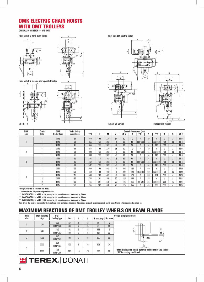
DMK ELECTRIC CHAIN HOISTS WITH DMT TROLLEYSOVERALL DIMENSIONS – WEIGHTS
DMK size
Chain falls
DMT trolley type
*Hoist trolley weight (kg)
Overall dimensions (mm)***J L M M1 Ф N O **O1 P **Q R S Ф T
11 SM2 29 340 100 236 54 52 72 / 20 / / / M161 EM3 58 355 135 362 -10 80 98 100(108) 54 260(280) 165 90 M141 CM3 41 355 135 362 -10 80 98 / 54 240 108 / M14
21 SM2 39 375 100 236 58 52 72 / 20 / / / M161 EM3 68 390 135 362 -6 80 98 100(108) 54 260(280) 165 90 M141 CM3 51 390 135 362 -6 80 98 / 54 240 108 / M14
31 SM3 62 462 135 362 -3 80 98 / 54 / / / M141 EM3 85 462 135 362 -3 80 98 100(108) 54 260(280) 165 90 M141 CM3 68 462 135 362 -3 80 98 / 54 240 108 / M14
4
1 SM4 105 560 160 402 -15 100 120 / 60 / / / M201 EM4 130 560 160 402 -15 100 120 110/(118) 60 266(286) 165 96 M201 CM4 115 560 165 402 -15 100 120 / 60 264 160 / M202 SM5 160 755 201 510 70 125 155 / 55 / / / M242 EM5 190 755 201 510 70 125 155 130(130) 55 282(282) 208 110 M242 CM5 170 755 201 510 70 125 155 / 55 350 198 / M24
* Weight referred to 3m hook-run hoist.** Dimensions for 2 speed trolleys in brackets.*** SM3/EM3/CM3: for width > 220 mm up to 400 mm dimension J increases by 70 mm*** SM4/EM4/CM4: for width > 220 mm up to 400 mm dimension J increases by 60 mm*** SM5/EM5/CM5: for width > 220 mm up to 400 mm dimension J increases by 75 mmNote When the hoist is equipped with raise/lower limit switches, dimension J increases as much as dimensions A and E, page 11 and note regarding the chain box
MAXIMUM REACTIONS OF DMT TROLLEY WHEELS ON BEAM FLANGEDMK size
Max capacity(kg)
DMT trolley type
Overall dimensions (mm)Ф r i b *R max (kg) Sp max
1 250SM2 52 5 15 80 17
* Max R calculated with a dynamic coefficient of 1.15 and no “M” increasing coefficient
EM3/CM3 80 7 16 87 22
2 500SM2 52 5 15 154 17
EM3/CM3 80 7 16 161 22
3 1000SM3
EM3/CM380 7 16 309 22
42000
SM4EM4/CM4
100 9 19 608 24
4000SM5
EM5/CM5125 14 29 1193 20
Hoist with CM manual gear operated trolley
Hoist with SM hand-push trolley Hoist with EM electric trolley
J1 = E1 - A 1 chain fall version 2 chain falls version

13
DMK ELECTRIC CHAIN HOISTSLOW HEAD ROOM EXECUTION OVERALL DIMENSIONS – WEIGHTS
DMK size
Max capacity(kg)
DMT trolley type
*Hoist trolley weight (kg)
Overall dimensions (mm)A B H ***H1 J L M M1 Ф N O **O1 P **Q R S Ф T Ф T1
1 250SM3+SM3 60 170 228 295 417 240 135 742 380 80 98 / 54 / 108 / M14 M16SM3+EM3 75 170 228 295 417 240 135 742 380 80 98 100/(108) 54 260/(280) 108 196 M14 M16
2 500SM3+SM3 67 176 240 315 455 265 135 762 400 80 98 / 54 / 108 / M14 M16SM3+EM3 80 176 240 315 455 265 135 762 400 80 98 100/(108) 54 260/(280) 108 196 M14 M16
3 1000SM3+SM3 100 190 275 365 510 327 135 812 450 80 98 / 54 / 108 / M14 M16SM3+EM3 115 190 275 365 510 327 135 812 450 80 98 100/(108) 54 260/(280) 108 196 M14 M16
42000
SM4+SM4 155 205 310 440 637 400 160 902 500 100 120 / 60 / 118 / M20 M24SM4+EM4 170 205 310 440 637 400 160 902 500 100 120 110/(118) 60 266/(286) 118 202 M20 M24
4000UPON REQUEST / / / / / / / / / / / / / / / / / /UPON REQUEST / / / / / / / / / / / / / / / / / /
* Weight referred to 3m hook-run hoist.** Dimensions for 2 speed trolleys in brackets*** Weight referred to 3m hook-run hoistWith application of an electric raise/lower limit switch dimension H1 increases by 25mm and dimension J increases by: DMK1+45mm; DMK2+40mm; DMK3+45mm; DMK4(1 fall)+60mm
MAXIMUM REACTIONS OF DMT TROLLEY WHEELS ON BEAM FLANGE FOR DMK LOW HEAD ROOM EXECUTION
DMK size
Max capacity(kg)
DMT trolley type
Overall dimensions (mm)Ф r i b *R max (kg) Sp max
1 250SM3+SM3
80 7 1644
18
* Max R calculated with a dynamic coefficient of 1.15 and no “M” increasing coefficient
SM3+EM3 45
2 500SM3+SM3
80 7 1680
18SM3+EM3 82
3 1000SM3+SM3
80 7 16156
18SM3+EM3 158
4
2000SM4+SM4
100 9 19307
21SM4+EM4 309
4000
SM5+SM5(UPON REQUEST)
125 14 29/ /
SM5+EM5(UPON REQUEST) / /
2 chain falls version

14
TECHNICAL SPECIFICATIONS AND DATA FOR DMK CHAIN HOIST, CLIMBING EXECUTIONCapacity
(kg)FEM group
DMK type Chain falls Lifting speed (mm) Lifting motor power (kw) * Hoist weight
(kg) Chain type Chain weight per meter(kg/m)1 Speed 2 Speed 1 Speed 2 Speed
125 2m 154C 1 8 / 0.2 / 17 4X12 0.38
2502m 134C 1 4 / 0.2 / 17 4X12 0.382m 234C 1 8 / 0.4 / 24 5x15 0.58
5002m 214C 1 4 / 0.4 / 24 5x15 0.582m 334C 1 8 / 0.8 / 38 7x21 1.16
10002m 314C 1 4 / 0.8 / 38 7x21 1.162m 434C 1 8 / 1.6 / 65 10x28 2.42
2000 2m 414C 1 4 / 1.6 / 65 10x28 2.42* Hoist weight without chain
DMK size
Max capacity(kg)
DMK hoist type
Overall dimensions (mm)A B C C1 D E E1 F F1 G G1 H
1125 154C 24 67 355 19 120 710 400 230 360 210 310 19250 134C 24 67 355 19 120 710 400 230 360 210 310 19
2250 234C 28 83 438 22 135 740 465 230 360 225 325 24500 214C 28 83 438 22 135 740 465 230 360 225 325 24
3500 334C 34 103 514 29 160 800 577 230 360 250 350 311000 314C 34 103 514 29 160 800 577 230 360 250 350 31
41000 434C 40 127 583 38 200 880 716 230 360 307 410 402000 414C 40 127 583 38 200 880 716 230 360 307 410 40
TYPES OF TENSION RODS BASED ON MIN. AND MAX. BEAM DIMENSIONSTrolley type Beam type Group 1 Group 2 Group 3 Group 4 * Minimum radius of monorail
internal curvature (mm)Beam Flange Beam Flange Beam Flange Beam Flange
SM2INP 80÷160 42÷74 180÷280 82÷119 300÷380 125÷149 400 155
1000IPE 80÷140 46÷73 160÷240 82÷120 270÷300 135÷150 330÷500 160÷200HEA - - 100÷120 100÷120 140 140 160÷200 160÷200
SM3INP 120÷240 58÷106 260÷450 113÷170 475÷600 178÷215 - -
1300IPE 120÷220 64÷110 240÷360 120÷170 400÷600 180÷220 - -HEA - - 140÷160 140÷160 180÷220 180÷220 - -
SM4INP 160÷280 74÷119 300÷475 125÷178 500÷600 185÷215 - -
1500IPE 160÷240 82÷120 270÷400 135÷180 450÷600 190÷220 - -HEA - - 160÷180 160÷180 200÷220 200÷220 - -
SM5INP 180÷300 82÷125 320÷500 131÷185 550÷600 200÷215 - -
1900IPE 180÷240 91÷120 270÷400 135÷180 450÷600 190÷220 - -HEA - - 180 180 200÷240 200÷240 - -
CM3INP 140÷240 66÷106 260÷450 113÷170 475÷600 178÷215 - -
1300IPE 140÷220 73÷110 240÷360 120÷170 400÷600 180÷220 - -HEA - - 140÷160 140÷160 180÷220 180÷220 - -
CM4INP 180÷280 82÷119 300÷475 125÷178 500÷600 185÷215 - -
1500IPE 180÷240 91÷120 270÷400 135÷180 450÷600 190÷220 - -HEA - - 160÷180 160÷180 200÷220 200÷220 - -
CM5INP 220÷300 98÷125 320÷500 131÷185 550÷600 200÷215 - -
1900IPE 220÷240 110÷120 270÷400 135÷180 450÷600 190÷220 - -HEA - - 180 180 200÷240 200÷240 - -
EM3INP 120÷240 58÷106 260÷450 113÷170 475÷600 178÷215 - -
1300IPE 120÷220 64÷110 240÷360 120÷170 400÷600 180÷220 - -HEA - - 140÷160 140÷160 180÷220 180÷220 - -
EM4INP 160÷280 74÷119 300÷475 125÷178 500÷600 185÷215 - -
1500IPE 160÷240 82÷120 270÷400 135÷180 450÷600 190÷220 - -HEA - - 160÷180 160÷180 200÷220 200÷220 - -
EM5INP 180÷300 82÷125 320÷500 131÷185 550÷600 200÷215 - -
1900IPE 180÷240 91÷120 270÷400 135÷180 450÷600 190÷220 - -- - 180 180 200÷240 200÷240 - -
NOTE: For EM trolleys with electric travel limit switches, check the R dimensions on page 12* Electric trolleys suitable to run on a bend with guide roller kit
OVERALL DIMENSIONS - WEIGHTS

15
SPECIFICATIONS OF MOTORS, FUSES AND POWER CABLES
Hoist type
Motor type Poles Power
(kW)
Power factorCOS v
Ia 50Hz (In) 50Hz Fuses aM Power cable section400V - ( ΔU20V )
380VA
400VA
415VA
400VA φ mm2 L =m
134C-154C 71C4AS1/1 4 0.2 0.43 3.8 (1.4) 4 1.5 ≤100112D-132D 72K1AS1/1 2/6 0.2/0.06 0.6/0.5 3.3/1.8 (0.8/0.8) 4 1.5 ≤100
232C 80C2AS2/2 2 0.4 0.45 6.5 (2.5) 4 1.5 ≤100214C-234C 80C4AS2/2 4 0.4 0.48 6.4 (2.1) 4 1.5 ≤100214D-234D 81K5AS2/2 4/12 0.4/0.12 0.6/0.6 5.2/3 (1.6/2) 4 1.5 ≤100
332C 90C2AS3/2 2 0.8 0.6 14.5 (4.8) 6 1.5 ≤70314C-334C 90C4AS3/2 4 0.8 0.46 14 (5.2) 6 1.5 ≤70314D-334D 91K5AS3/3 4/12 0.8/0.24 0.6/0.5 14.6/4 (3.1/2.6) 6 1.5 ≤70
432C 100C2AS4/2 2 1.6 0.7 32 (6.2) 10 2.5 ≤50414C-434C 100C4AS4/2 4 1.6 0.6 28 (6.5) 10 2.5 ≤60424L-434L 101K4AS4/2 4 2.5 0.7 38 (6.2) 10 2.5 ≤40414D-434D 101K5AS4/2 4/12 1.6/0.5 0.62/0.4 28/12 (5.5/6) 10 2.5 ≤60424D-454D 101K5AS4/4 4/12 2/0.65 0.72/0.5 28/8 (6.5/5) 10 2.5 ≤60
Single-phase hoist
Motor type Poles Power
(kW)
Power factorCOS v
Ia 50Hz (In) 50Hz Fuses aM Power cable sectione230V - ( ΔU20V )
230VA
230VA φ mm2 L =m
132M-112M 72K2AM1/1 2 0.2 0.9 9.6 (3.2) 6 1.5 ≤ 60234M-214M 81K4AM2/1 4 0.4 0.9 11.3 (5.2) 10 1.5 ≤ 50334M-314M 91K4AM3/2 4 0.8 0.9 32 (12) 20 2.5 ≤ 30
Trolley type Motor type Poles Powera
( kW )Power factor
COS vIa - ( A )
400V - 50HzIn - ( A )
400V - 50Hz
EM3-EM4 71C4TV1/1 4 0.25 0.43 3.8 1.4EM3-EM4 71C8TS1/1 8 0.12 0.53 2.5 1.3EM3-EM4 72K6TS1/1 6 0.18 0.5 3 1.7
EM3-EM4-EM5 81C5AD2/1 4/12 0.25/0.08 0.54/0.7 4.5/1.8 1.4/1.2EM5 80C4TV2/1 4 0.37 0.7 4.4 1.7EM5 80C8TS2/1 8 0.17 0.5 2.6 1.6EM5 80C6TS2/1 6 0.25 0.5 3.8 1.2

www.donati-europe.comDONATI SOLLEVAMENTI S.r.l.Via Quasimodo, 17 - 20025 Legnano (Milano) - ItaliaTel. +39 0331 14811 - Fax. +39 0331 1481880e-mail: [email protected], [email protected]
Factory:Via Archimede, 52 - 20864 Agrate Brianza (MB) - Italia
TMAN
03CG
00