Embed Size (px)
Citation preview

Electric Chain Hoist
Model CPE/FCapacity 1.600 kg - 10.000 kg
Translated Operating and Maintenance Manual
COLUMBUS McKINNON Industrial Products GmbHP. O. Box 11 01 53 • D-42301 Wuppertal, Germany
Yale-Allee 30 • D-42329 Wuppertal, Germany
+49 (0) 202/6 93 59-0 • Fax + 49 (0) 202 / 6 93 59-127
Ident.-No.: SA_09901074/02.2017


2
© 2017 Columbus McKinnon Industrial Products GmbH
1. GENERAL INFORMATION
Attention: All users must read these operating instructions carefully prior to the initial operation. These instructions are intended to acquaint the user with the hoist/trolley and enable him to use it to the full extent of its intended capabilities. The operating instructions contain important information on how to handle the hoist/trolley in a safe, correct and economic way. Acting in accordance with these instructions helps to avoid dangers, reduce repair costs and downtime and to increase the reliability and lifetime of the hoist/trolley. Anyone involved in doing any of the following work with the hoist/trolley must read the operating instructions and act accordingly:
• Operation, including preparation, trouble shooting and cleaning
• Maintenance, inspection, repair
• Transport Apart from the operating instructions and the accident prevention act valid for the respective country and area where the hoist / trolley is used, also the commonly accepted regulations for safe and professional work must be adhered to. The user is responsible for the proper and professional instruction of the operating personnel. Every unit leaving the factory is furnished with a test certificate that shows the serial number of the hoist / trolley. This certificate should be filed together with the inspection manual. The continuous sound level at the place of work is equal to >70 dB. The measurements were taken at a distance of 1 m from the hoist at 9 positions in accordance with DIN 45635, precision class 2.
2. CORRECT OPERATION
Maximum capacity
The Yale electric chain hoist series CPE/F has been designed to lift and lower loads up to the rated capacity. The lifting capacity indicated on the hoist/trolley is the maximum safe working load which must not be exceeded.
Danger zones
• Do not allow personnel to pass under a suspended load.
• After lifting or tensioning, a load must not be left unattended.
• Start moving the load only after it has been attached correctly and all personnel are clear of the danger zone.
Attaching the hoist / trolley
The operator must ensure that the hoist / trolley is attached in a manner that does not expose himself or other personnel to danger by the hoist, trolley, chain(s) or the load.
Temperature range The units can be operated in ambient temperatures between -20° C and +50° C. Consult the manufacturer in case of extreme working conditions.
3
© 2017 Columbus McKinnon Industrial Products GmbH
Theoretical service life
The electric chain hoist is classified to group 1 Am according to FEM 9.511. Basic principles for the calculation of the theoretical remaining service life are given in BGV D8. When the theoretical remaining service life has been reached, the electric chain hoist should be subjected to a general overhaul (also refer to para 8 INSPECTION AND MAINTENANCE). Earlier overhaul and maintenance is recommended for electric chain hoists that are used in extreme conditions (such as underground mining)
Regulations
The accident prevention act and/or safety regulations of the respective country for using manual and electric hoists must be strictly adhered to. In Germany these are BGV D6, BGV D8, BGR 500 and VDE 0113-32/EN 60204-32:1999.
Maintenance / Repair
In order to ensure correct operation, not only the operating instructions, but also the conditions for inspection and maintenance must be complied with. If defects are found or abnormal noise heard, stop using the hoist / trolley immediately. Attention: Before starting work on electrical components the power supply must be cut off.
3. INCORRECT OPERATION
• Do not exceed the rated capacity of the hoist / trolley. • Do not attempt to lift stuck or jammed loads. • Excessive inching operation by short and frequent actuation
of the control switch should be avoided. • Do not use the hoist/trolley for the transportation of people
(Fig. 1). • Welding on hooks and load chain is strictly forbidden. The
load chain must never be used as a ground connection during welding (Fig. 1).
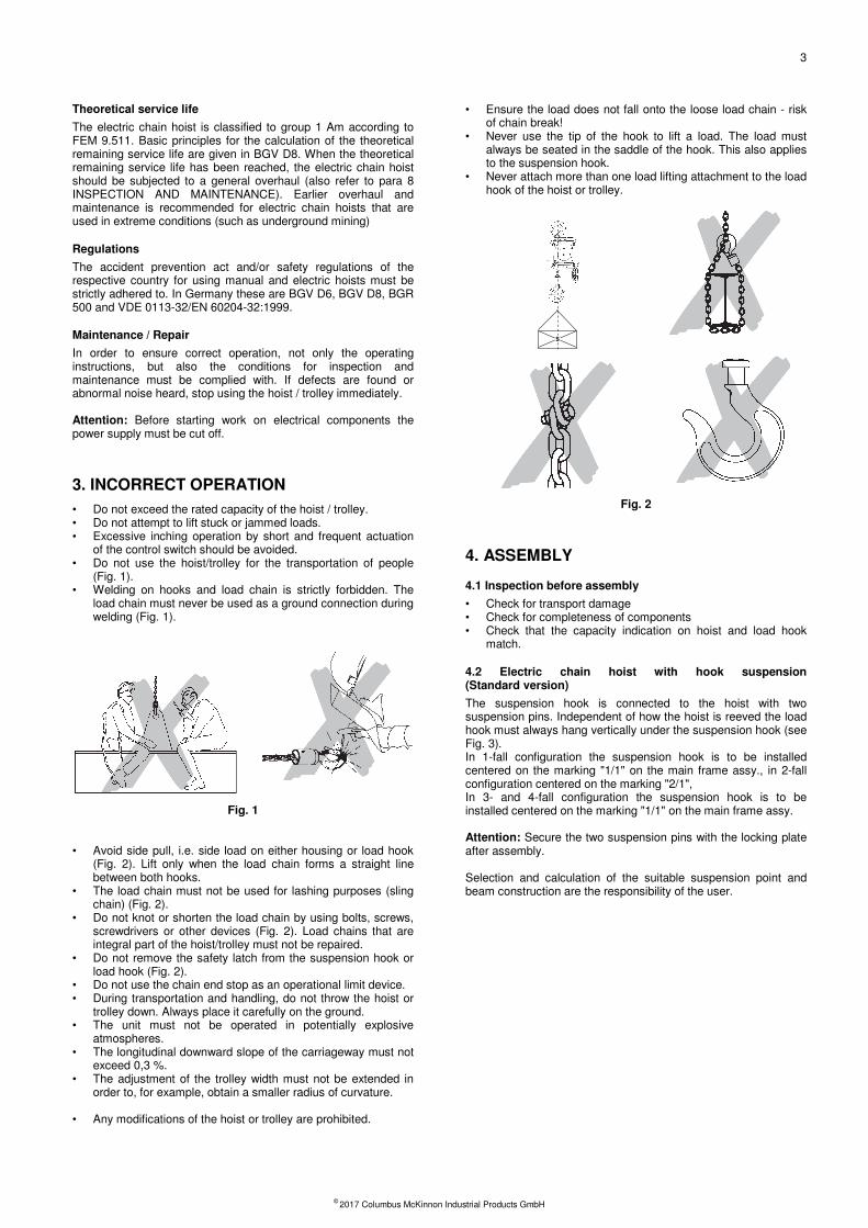
Fig. 1 • Avoid side pull, i.e. side load on either housing or load hook
(Fig. 2). Lift only when the load chain forms a straight line between both hooks.
• The load chain must not be used for lashing purposes (sling chain) (Fig. 2).
• Do not knot or shorten the load chain by using bolts, screws, screwdrivers or other devices (Fig. 2). Load chains that are integral part of the hoist/trolley must not be repaired.
• Do not remove the safety latch from the suspension hook or load hook (Fig. 2).
• Do not use the chain end stop as an operational limit device. • During transportation and handling, do not throw the hoist or
trolley down. Always place it carefully on the ground. • The unit must not be operated in potentially explosive
atmospheres. • The longitudinal downward slope of the carriageway must not
exceed 0,3 %. • The adjustment of the trolley width must not be extended in
order to, for example, obtain a smaller radius of curvature.
• Any modifications of the hoist or trolley are prohibited.
• Ensure the load does not fall onto the loose load chain - risk of chain break!
• Never use the tip of the hook to lift a load. The load must always be seated in the saddle of the hook. This also applies to the suspension hook.
• Never attach more than one load lifting attachment to the load hook of the hoist or trolley.
Fig. 2
4. ASSEMBLY
4.1 Inspection before assembly
• Check for transport damage • Check for completeness of components • Check that the capacity indication on hoist and load hook
match.
4.2 Electric chain hoist with hook suspension (Standard version)
The suspension hook is connected to the hoist with two suspension pins. Independent of how the hoist is reeved the load hook must always hang vertically under the suspension hook (see Fig. 3). In 1-fall configuration the suspension hook is to be installed centered on the marking "1/1" on the main frame assy., in 2-fall configuration centered on the marking "2/1", In 3- and 4-fall configuration the suspension hook is to be installed centered on the marking "1/1" on the main frame assy. Attention: Secure the two suspension pins with the locking plate after assembly. Selection and calculation of the suitable suspension point and beam construction are the responsibility of the user.
S

4
© 2017 Columbus McKinnon Industrial Products GmbH
Fig. 3
4.3 Electric chain hoist with trolley
The units are delivered pre-assembled and are built to fit beam range A or B which is given on the name plate (Tab. 1). Prior to installation ensure that the flange width is within the limits indicated.
Assembly of the trolley 1,6 - 5t (see Fig. 4) 1. Unscrew the locking nuts (item 9) and hex nuts (item 2) from the crossbars (item 1) and remove both side plates (item 6) from the trolley. 2. Measure the flange width of the beam (see Fig. 4 - measure b). 3. Adjust measure B between the shoulders of the round nuts (item 5) on the threaded crossbars (item 1). Ensure that the 4 bores in the round nuts face towards the outside. Adjust the measure B to equal measure b plus 4 mm. Measure A must be 2 mm on either side and the centre traverse (item 4) must be centred between the round nuts. 4. Replace one side plate (item 6): Replace one side plate ensuring that the roll pins (item 8) engage into one of the 4 bores in the round nuts (item 5). To achieve this it may be necessary to rotate the round nuts slightly. 5. Replace the washers (item 3) and tighten the hex nuts (item 2). Screw on the locknuts (item 9) finger-tight and tighten a further ¼ to ½ turn. Attention: The locknuts must always be fitted.
6. Loosely replace the second side plate (item 6) on the crossbars (item 1). The washers (item 3), hex. nuts (item 2) and locknuts (item 9) can be fitted loosely. 7. Raise the complete pre-assembled trolley to the carrying beam. 8. Engage the second side plate (item 6) ensuring that the roll pins (item 8) engage into one of the bores in the round nuts (item To achieve this it may be necessary to rotate the round nuts slightly. 9. Tighten the hex nuts (item 2) on the second side plate. Tighten the locknuts (item 9) finger-tight and then a further ¼ to ½ turn. Attention: The locknuts must always be fitted! 10. By traversing the trolley check the following:
• that a clearance of 2 mm is maintained on each side between the trolley wheel flanges and the beam outer edge.
• that the suspension traverse and consequently the unit is centered below the beam.
• that all 4 locknuts (item 9) are fitted.
• that the side plates are parallel.
• that all wheels roll freely and make good contact with the flange of the beam.
• that there are no obstacles on the driving surface of the beam.
Fig. 4
Assembly of the trolley 7,5 - 10 t (see Fig. 5 and Fig. 6) 1. Measure the flange width of the beam. 2. Evenly distribute the spacer sleeves and spacer washers on both sides of the load bar. The clearance between the trolley wheel flange and the beam edge must be 2 mm on both sides when finally assembled.
Capacity
[kg]
Beam
range
Flange width
[mm]
Flange thickness
[mm]
min. max. max.
1.600 - 5.000 A 98 180 27
1.600 - 7.000 B 180 300 27
7.500 - 10.000 B 125 310 40
Tab. 1
AA
B
b
29
1
34 5
8
6
72 mmA
5
3
29
b
B
10
5
© 2017 Columbus McKinnon Industrial Products GmbH
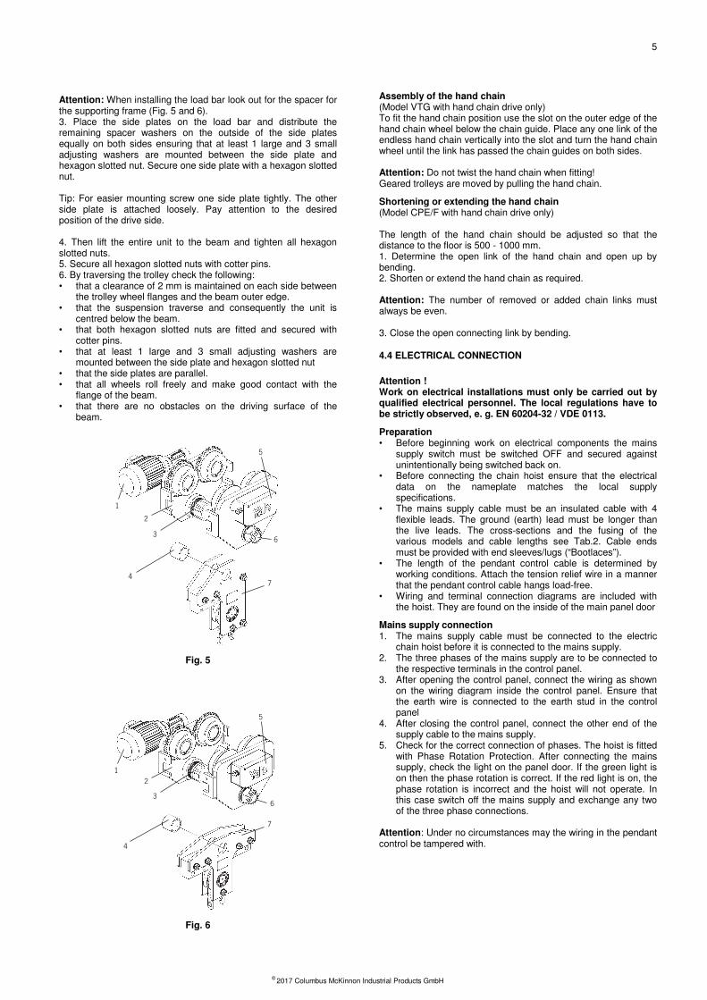
Attention: When installing the load bar look out for the spacer for the supporting frame (Fig. 5 and 6). 3. Place the side plates on the load bar and distribute the remaining spacer washers on the outside of the side plates equally on both sides ensuring that at least 1 large and 3 small adjusting washers are mounted between the side plate and hexagon slotted nut. Secure one side plate with a hexagon slotted nut. Tip: For easier mounting screw one side plate tightly. The other side plate is attached loosely. Pay attention to the desired position of the drive side. 4. Then lift the entire unit to the beam and tighten all hexagon slotted nuts. 5. Secure all hexagon slotted nuts with cotter pins. 6. By traversing the trolley check the following: • that a clearance of 2 mm is maintained on each side between
the trolley wheel flanges and the beam outer edge. • that the suspension traverse and consequently the unit is
centred below the beam. • that both hexagon slotted nuts are fitted and secured with
cotter pins. • that at least 1 large and 3 small adjusting washers are
mounted between the side plate and hexagon slotted nut • that the side plates are parallel. • that all wheels roll freely and make good contact with the
flange of the beam. • that there are no obstacles on the driving surface of the
beam.
Fig. 5
Fig. 6
Assembly of the hand chain (Model VTG with hand chain drive only) To fit the hand chain position use the slot on the outer edge of the hand chain wheel below the chain guide. Place any one link of the endless hand chain vertically into the slot and turn the hand chain wheel until the link has passed the chain guides on both sides. Attention: Do not twist the hand chain when fitting! Geared trolleys are moved by pulling the hand chain.
Shortening or extending the hand chain (Model CPE/F with hand chain drive only) The length of the hand chain should be adjusted so that the distance to the floor is 500 - 1000 mm. 1. Determine the open link of the hand chain and open up by bending. 2. Shorten or extend the hand chain as required. Attention: The number of removed or added chain links must always be even. 3. Close the open connecting link by bending.
4.4 ELECTRICAL CONNECTION
Attention ! Work on electrical installations must only be carried out by qualified electrical personnel. The local regulations have to be strictly observed, e. g. EN 60204-32 / VDE 0113.
Preparation • Before beginning work on electrical components the mains
supply switch must be switched OFF and secured against unintentionally being switched back on.
• Before connecting the chain hoist ensure that the electrical data on the nameplate matches the local supply specifications.
• The mains supply cable must be an insulated cable with 4 flexible leads. The ground (earth) lead must be longer than the live leads. The cross-sections and the fusing of the various models and cable lengths see Tab.2. Cable ends must be provided with end sleeves/lugs (“Bootlaces”).
• The length of the pendant control cable is determined by working conditions. Attach the tension relief wire in a manner that the pendant control cable hangs load-free.
• Wiring and terminal connection diagrams are included with the hoist. They are found on the inside of the main panel door
Mains supply connection 1. The mains supply cable must be connected to the electric
chain hoist before it is connected to the mains supply. 2. The three phases of the mains supply are to be connected to
the respective terminals in the control panel. 3. After opening the control panel, connect the wiring as shown
on the wiring diagram inside the control panel. Ensure that the earth wire is connected to the earth stud in the control panel
4. After closing the control panel, connect the other end of the supply cable to the mains supply.
5. Check for the correct connection of phases. The hoist is fitted with Phase Rotation Protection. After connecting the mains supply, check the light on the panel door. If the green light is on then the phase rotation is correct. If the red light is on, the phase rotation is incorrect and the hoist will not operate. In this case switch off the mains supply and exchange any two of the three phase connections.
Attention: Under no circumstances may the wiring in the pendant control be tampered with.
2
1
5
36
47
1
5
2
36
4
7

6
© 2017 Columbus McKinnon Industrial Products GmbH
5. FUNCTIONAL CHECK AFTER ASSEMBLY
Prior to operating the hoist, grease the trolley pinions (manual geared and electric trolleys) and lubricate the load chain when it is not under load (see 8.3). Before the hoist is put into regular service, the following additional inspections must be made: • Are all screwed connections on hoist and trolley tight and are
all locking devices in place and secure? • Are the end stops on the trolley runway in place and secure? • Is the chain drive correctly reeved? • Is the chain end stop correctly fitted to the loose end of the
load chain? • All units equipped with two or more chain falls should be
inspected before initial operation for twisted or kinked chains. The chains of 2-fall hoists could have been twisted if the bottom block is rolled over.
• Perform an operation cycle without load. The chain should move in a steady, smooth way. Check the function of the overload device by raising the bottom block against the hoist body (max. 5 sec.).
• Check the brake function when lifting and lowering. The braking distance must not be more than 50 mm.
• Traverse the trolley (if available) the complete length of the trolley runway ensuring that the 2 - 4 mm lateral clearance between the trolley wheel flange and the beam outer edge is maintained at all times. Check that beam end stops are positioned correctly and secure.
6. COMMISSIONING
Inspection before initial operation Each hoist/trolley must be inspected prior to initial operation by a competent person and any problems attended to. The inspection is visual and functional. These inspections have to ensure that the hoist is safe and has not been damaged by incorrect transport or storage. Inspections should be made by a representative of the manufacturer or the supplier although the company can assign its own suitably trained personnel. Inspections are instigated by the user.
Inspection by a crane expert If the hoist is used as a crane, it has to be inspected and approved by a crane expert before initial operation. This inspection has to be registered in the crane inspection book. The inspection by the crane expert has to be instigated by the operating company.
7. OPERATION
Installation, service, operation Operators delegated to install, service or independently operate the hoist must have had suitable training and be competent. Operators are to be specifically nominated by the company and must be familiar with all relevant safety regulations of the country of use.
Inspection before starting work Before starting work inspect the hoist/trolley, chains and all load bearing components every time for visual defects. Furthermore test the brake and make sure that the load and hoist/trolley are correctly attached by carrying out a short work cycle of lifting and lowering, travelling in both directions. Selection and calculation of the proper suspension point and beam construction are the responsibility of the operating company.
Inspection of load chain Inspect the chain for sufficient lubrication and visually check for external defects, deformations, superficial cracks, wear or signs of corrosion.
Inspection of chain end stop The chain end stop must be connected to the free (idle) chain fall.
Inspection of chain reeving All units with two or more chain falls should be inspected prior to initial operation for twisted or kinked chains. The chains of 2-fall hoists may have been twisted if the bottom block was rolled over (Fig. 7). The load chain must be installed according to illustration (Fig. 3). Hereby the welds on the standing links must face away from the load sheave.
Tab. 2

7
© 2017 Columbus McKinnon Industrial Products GmbH
Fig. 7
Inspecting the hooks Check the load hook and the suspension hook for deformations, cracks, damages, abrasion, signs of corrosion and easy swiveling action of the load hook.
Attaching the load The load must always be seated in the saddle of the hook. Never attach the load to the tip of the load hook (Fig. 7). This also applies to the suspension hook.
Inspect the traverse movement (for trolleys) Inspect the traverse for correct assembly and visually check for external defects, deformations, superficial cracks, wear or signs of corrosion. Especially make sure that the roll pins are properly fitted to the center traverse (Fig. 4).
Check adjustment of trolley width On chain hoists with trolley (CPE/F-VTP/G(E) check that the clearance between the trolley wheel flange and the beam outer edge is equal on both sides and within the tolerances given (see Fig. 4). Enlarging the clearances, e. g. to enable the trolley to negotiate tighter curves, is forbidden.
Traversing the hoist Plain trolley: Push the hoist or attached load. Attention: Never pull on the pendant control cable. Suspended loads may only be pushed. Geared trolley: By operating the trolley hand chain. Electric trolley: By operating the ► and ◄-buttons. For trolleys with two speeds: The first stage of button depression activates the slow speed. Further depression activates the fast speed. Use the slow speed for short periods only. When moving the trolley consider the stopping distance. Do not use the beam end stops as operational limit devices.
Attaching the load Attach the load to the hoist using only approved and certified slings or connection devices. Never use the load chain as sling chain. The load must always be seated in the saddle of the hook. Never attach the load to the tip of the hook. Do not remove the safety latch from the load hook.
Lifting/lowering the load The load is lifted by depressing the ▲-button. It is lowered by depressing the ▼-button. For hoists with two speeds: The first stage of button depression activates the slow speed, further
depression activates the faster speed. In order to position the chain to take up the load, always use the lowest available lifting speed. The chain must be loaded at this speed and must not lie slack on the floor. The slow speed may only be used for short distances. The chain end stop must not be used as an operational limit switch. Use the slow speed for short periods only. Do not use the chain end stop as operational limit device.
Emergency stop All movement can be immediately halted by depressing the red, mushroom shaped button on the pendant control. Attention: Operating the red emergency button does NOT automatically disconnect the mains supply to hoist or trolley. To release the emergency stop, rotate the button in a clockwise direction.
8. INSPECTION AND MAINTENANCE
• Maintenance and inspections may only be carried out by a competent person.
• The inspection must determine that all safety devices are present and fully operational and covers the condition of the hoist, lifting gear, accessories and supporting constructions.
• The service intervals and inspections noted are for normal working conditions. Adverse working conditions, e. g. heat or chemical environments or underground mining, can dictate shorter periods.
• The Yale electric chain hoists CPE/F conform to FEM group 1 Am in accordance with FEM 9.511. This results in a theoretical service lifetime of 800 resp. 400 operating hours under full load.
• This is equivalent to 10 years under normal operating conditions. After this period the hoist requires a general overhaul. Again, adverse working conditions, e. g. heat or chemical environments or underground mining, can dictate shorter periods.
• Further information is contained in BGV D6 resp. FEM 9.755. Attention: Maintenance work requires subsequent function testing with nominal load.
8.1 Daily Checks
1. Visually check the pendant control switch and cable for damage. 2. Function test of brake 3. Function test of end limit switch 4. Electric chain hoists with trolley: • Check that the trolley runway is free from obstructions • Check that the end stops on the trolley runway are fitted and
secure. 5. Load Hook Assembly • Check for smooth swivel action – an indication that the thrust
bearing is operating correctly • Check for any gap between top of hook neck shoulder and
underside of crosshead. Maximum allowable gap 1mm • Check that the top end of the hook is level with or slightly
proud of the round nut

8
© 2017 Columbus McKinnon Industrial Products GmbH
8.2 Regular Inspections, Service and Testing
According to prevailing national/international occupational safety and health regulations, hoisting equipment must be inspected and tested at least annually by a competent person. Adverse working conditions may dictate shorter inspection periods. Repairs may only be carried out by specialist workshops that use original Yale spare parts. The inspection must determine that all safety devices are present and fully operational and cover the condition of the hoist, lifting gear, accessories and supporting constructions. If required by the Occupational Health and Safety Organization, the results of the adequate inspections and competent performance of repairs have to be substantiated. If the electric hoist (with capacity of 1 t and up) is installed in a carriage, or if the load is moved in one or several directions, the installation is considered to be a crane and the inspections should be carried out in accordance with BGV D6-Cranes. Attention! Power supply must be disconnected while inspecting the device, unless the type of the examination excludes this.
8.3 Load Chain
The load chains are case-hardened and carry the designations 11 x 31 DAT. The CPE/F electric hoists are specially designed to use this type of chain. For this reason only chains that have been approved by the manufacturer may be used in these hoists.
Lubricating the load chain The load chain is to be lubricated before initial operation and every month, however, latest after 50 operating hours. Adverse working conditions, e. g. excessive dust or continued heavy duty can dictate shorter periods between lubrication. • Before the chain is lubricated it must be cleaned. Flame
cleaning is forbidden. Use only cleansing methods and agents that do not corrode the chain material. Avoid cleansing methods that can lead to hydrogen brittleness, e g. spraying or dipping chain in caustic solvents. Also avoid surface treatments that can hide cracks and flaws or other surface damage.
• The chain must be lubricated in a no-load condition so that lubricant can enter between the links, e. g. by dipping in oil. The chain must be lubricated throughout its entire length.
• High pressure gearbox motor oil of the viscosity 100, e. g. Shell Tonna T68 can be used to lubricate the chain. For very dusty applications use a dry lubricant.
Inspecting the load chain for wear Load chains must be inspected every 3 months or the latest after 200 operating hours, depending on operating conditions. Visually inspect the chain over its full length for deformation, cracks, flaws, elongation, wear or corrosive pitting. Load chains must be replaced when the nominal diameter “d” on any part of the chain has been reduced by more than 10 % or when the pitch “t” is elongated by more than 5 % or over 11 pitches (11 x t) by 2 %. Nominal dimensions and wear limits are shown in the following Tab. 3. Chains that do not fulfil all requirements must be replaced immediately.
Fig. 8
Replace the load chain
1-fall design 1. Disassemble bottom block Remove the circlip with suitable pliers. Raise the swivel tube in the direction of the chain and tap out the chain bolt with a punch. Attention: Do not damage the chain bolt bore. 2. Remove the chain end stop. Remove the 2 screws. The chain is now free. 3. Fitting the new chain Cut the second to last link open on the loose end of the load chain to form a "C". Remove the last link and connect the new chain. The new chain must be fitted so that the welds on the standing links face towards the chain guide and away from the load sheave. Operate the hoist in the lowering direction (6-button) to feed the chain through the hoist. 4. Fitting lower block and chain end stop Slide the end buffers over the loose ends of the load chain and refit bottom block and chain end stop. The chain end stop must be fitted so that at least 1 link remains free. Attention: Use new hexagon locknuts. 5. Before initial operation lubricate the unloaded chain and test all hoist functions under no-load condition.
2-fall design
1. Remove the chain anchor bolt The chain anchor bolt is situated on the underside of the hoist body. With an allen key remove the grub screw that serves as locking device. Tap out the chain anchor bolt with a punch from the other side. Attention: Take care not to damage the anchor bolt or bore. 2. Pull the load chain through the bottom block and remove the chain end stop. 3. Fitting the new chain Cut the second to last link open on the loose end of the load chain to form a "C". Remove the last link and connect the new chain. The new chain must be fitted so that the welds on the standing links face towards the chain guide in the housing. Operate the hoist in the lowering direction (▼-button) to feed the chain through the hoist. 4. Replace chain end stop Slide the buffer pad over the loose end of the load chain and refit the chain end stop ensuring that at least 1 link remains free. 5. Fitting the chain anchor bolt Inspect the chain anchor bolt for flaws, cracks or burrs. Enter the last link of the other load chain end into the slot in the underside of the hoist body. Attention: Check that the chain is not twisted. Now enter the chain anchor bolt through the side bore. Move the last link back and forth while entering the chain anchor bolt to ensure that it is not trapped and damaged by the anchor bolt. Secure the anchor bolt with the grub screw.
Link chains 11 x 31 DAT
InspectionDimension
[mm]
Nominal value
[mm]
Wear limit
[mm]
Length over 11 pitches 11 x t 341 347
Length of 1 pitch t 31 32
Diameter d 11,3
Mean thicknessd
1 + d
2
211,3 10,2
Tab. 3
t11 x t
d
d = Nenndicke der Kette / Nominal thickness of chain
Epaisseur nominale de la chaîne
d1, d
2 = Istwert / Actual value / Valeur réelle
d1 + d
2d
min. = ≤ 0,9 d
2
d1
d2

9
© 2017 Columbus McKinnon Industrial Products GmbH
6. Assemble the load block Check the idler sheave for damage. Position the load chain over the idler sheave ensuring that the welds on the standing links face away. Grease the needle bearings in the bottom block halves. See recommended lubricant specification (Appendix 2). Place the load hook assembly in the slot provided in one of the bottom block halves and push the complete unit onto the idler sheave. Ensuring that the buffer pad is situated correctly in its groove, replace the second bottom block half and secure with the screws. 7. Functional test All units with two or more chain falls must be inspected before every operation for twisted or kinked chains. Chains on 2-fall units may have become twisted if the bottom block is rolled over. If a chain is twisted disconnect it from the hoist and re-thread it correctly. In some cases it may be necessary to remove the last link. 8. Before initial operation lubricate the unloaded chain and test all hoist functions under a no-load condition.
8.4 Maintenance Load Hook
Inspect the hook for deformation, damage, surface cracks, wear and signs of corrosion as required, at least annually. Adverse working conditions may dictate shorter periods. Hooks that do not fulfil all requirements must be replaced immediately. Welding on hooks to compensate for wear or damage is not permissible. Hooks fitted with lubrication points on the side of the housing should be lubricated. See recommended lubricant specification (Appendix 2). Hooks must be replaced when the mouth of the hook has opened more than 10 % or the nominal value of other dimensions has decreased by 5 % due to wear. Nominal dimensions and wear limits are shown in Tab. 4.
Fig. 9
Tab. 4
Inspection of bottom block bearings The bottom hook bearings should be inspected at least annually, and lubricated. See appendix 2 for detailed instructions.
8.5 Maintenance Trolleys
In particular check following parts: • Side plate: For cracks or deformation in particular around the
areas of screwed connections. • Trolley wheels: Visually check for cracks and wear on trolley
wheel flanges. Grease the transmission. • Crossbars: In particular around threaded areas for cracks. • Fasteners: Check nuts, screws and locking devices for
tightness.
8.6 Maintenance of Overload Protection Device
Overload protection device The unit is equipped with an overload protection device as standard. This device is factory set to min. 125 % + 10 % of the rated capacity and prevents serious overloading of the hoist during lifting of loads. Adjustment and testing of the overload device may only be carried out by authorized competent persons. The force-limit factor according EN 14492-2:2006 amounts φDAL=1,35. The maximum force occurring when the rated capacity limiter operates will be calculated as: FLIM = (φDAL x mRC + mH - mRC) x g φDAL = 1,35 mRC = Rated capacity of the hoist [kg] mH = Hoist load [kg] Hoist load mH: Load which includes all the masses of a load equal to the rated capacity of the hoist, the hoist medium and the fixed load lifting attachments, e. g. hooks, grabs, magnets, lifting beams, vacuum lifters. g = Acceleration due to gravity (9,81) [m/s
2]
Adjustment of overload device Attention: The adjustment of the overload device may only be done by authorized, competent personnel. Attention: During this job the hoist remains operable which can result in danger of injury by rotating parts. • Loosen the 4 screws of the gear box cover. • Loosen the threaded pin which is pressing the ball on the
cover to lock the straining screw. • Check the adjustment with a suitable load (min. 125 % of the
rated capacity). • Increase the moment of friction by turning the straining screw
in clockwise direction until the load is raised. Attention: The max. operating time of the overload device is 60 seconds. Thereafter the unit has to cool down to room temperature (min. 20 minutes). • Screw in the threaded pin (secured with Loctite
® 243)
• Screw on the gear box cover with the 4 cylinder screws.
8.7 Maintenance Of Gearbox
The gearbox is practically maintenance-free. Service is therefore reduced to changing the oil.
Oil change The gearbox oil should be changed after every 5 years, however, latest after 400 operating hours (oil volume: ca. 0,3 Litre). Attention: During oil change the electric power supply must be shut off.

10
© 2017 Columbus McKinnon Industrial Products GmbH
8.8 Motor
Motor Under normal conditions the motor is practically maintenance-free. Every 2 ½ years the bearings should be inspected cleaned and repacked half-full with grease. We recommend K 3 N / KL 3 N DIN 51825 / DIN 51502.
Electromagnetic Brake on Motor (Fig. 10) The electromagnetically released spring-applied brakes are failsafe brakes with two friction surfaces. The braking torque is generated by means of spring force. Inspection of Brake By removing the plug (2) the air gap and the thickness of the brake lining can be checked. The nominal air gap “sA” is 0,3mm and the maximum air gap sAmax is 0,5mm. The minimum thickness of the brake lining is 5,8mm. After that the plug (2) has to be mounted again. Attention: If either the air gap of the brake is bigger than 0,5mm or the thickness of the brake lining is less than 5,8mm the electromagnetic brake must be replaced. Attention: Do not allow the brake friction pads to come into contact with lubricant or similar!
Fig. 10
8.9 Electric Chain Hoist In General
In particular check following parts: • Threaded connections in general
Check all nuts, screws and locking devices for tightness. • Chain container
Ensure the chain container is securely fastened. Check for cracks or wear.
• Suspension bolt (Connection between hoist and suspension bracket resp. trolley) Check for cracks or wear. Ensure all safety devices are in place and secure.

Visually check the pendant control and cable for damage
Perform a hoist cycle without load and check for abnormal noise and operation
Ensure Emergency Stop button is functional
Check the condition of the beam for defects, cracks, wear and signs of corrosion
Check trolley width to ensure correct clearance between all wheels and beam outer edge (2 - 4mm)
Operate the trolley under no load to make sure it runs the full length of beam smoothly
Inspect the load chain for damage, corrosion and interlink wear as well as lubrication
Inspect the hook for damage, distortion, cracks, wear, stretch and corrosion
Check that hook swivel action is free and smooth
Check for any gap between top of shoulder of bottom hook and underside of crosshead*
Inspect screwed/threaded connections for tightness
Check that hook housings are flush (no gap between housing halves)**
When doing first lift, check brakes by raising load 10mm and confirm brake holding.
Apply a full load, hoist and then lower, stopping to check braking distance (50mm)
Appendix 1
Daily/Regular Inspection Check List
Date of Inspection: Inspected by:
*Checking gap between shoulder of bottom hook and underside of crosshead
**Check that housing halves are flush

1
INSPECTION AND LUBRICATION OF BOTTOM BLOCK BEARINGS
1) Loosen and remove the bolts that hold the housing together 5) Unscrew and remove round nut
2) Remove hook and cross head assembly part 6) The thrust bearing will now be visible
3) Using a 3 mm punch, remove the cotter pin 7)
4) Using the same punch loosen the nut 8)
Remove and inspect bearing for wear and corrosion. Replace if signs of wear or corrosion
Bolts
3mm Punch
Cotter Pin
Appendix 2
Nut
Washer
Thrust Bearing
Washer
Crosshead
Washer
Nut
3mm Punch
Washer
Washer
Insert Bearing
Liberally lubricate the thrust bearing and washers using a high viscosity acid resistant grease (eg. Fuchs Renolit LC-WP2), and insert into the crosshead.
Thrust Bearing
Crosshead assembly part

2
9) Insert threaded end of hook through crosshead and attach the round nut onto the threads.
10) With round nut screwed up almost to maximum position align the hole of the round nut that with the two holes of the crosshead, using the 3mm punch.
11) Insert a new cotter pin (do not re-use the old pin) using a 5mm punch and hammer. If necessary, keep the holes lined up by means of the 3mm punch.
12)
Inspect the needle bearings in the two half housings. Replace if necessary.
13) Liberally apply high viscosity acid resistant grease (eg. Fuchs Renolit LC-WP2) to the needle bearings in both halves of the housing
14) Attach the two housing halves and sheave to the crosshead assembly. Ensure the washers are placed
either side of the sheave shaft.
15) Insert and tighten bolts. One recess on housing is round (for bolt head) and opposite slot is hexagonal (for nut). Replace the lock nut each time.
16) Test for smooth swivel action of the hook in the housing.
Line up holes using punch
Sheave
Crosshead
Assembly
Needle bearings
IMPORTANT:
AFTER RE-ASSEMBLY OF THE BOTTOM BLOCK AND FITTED TO THE HOIST, THE HOIST MUST BE SUBJECTED TO A LOAD TEST.
Bolt head opposite side (round recess)
Nut one side (hexagonal
recess)
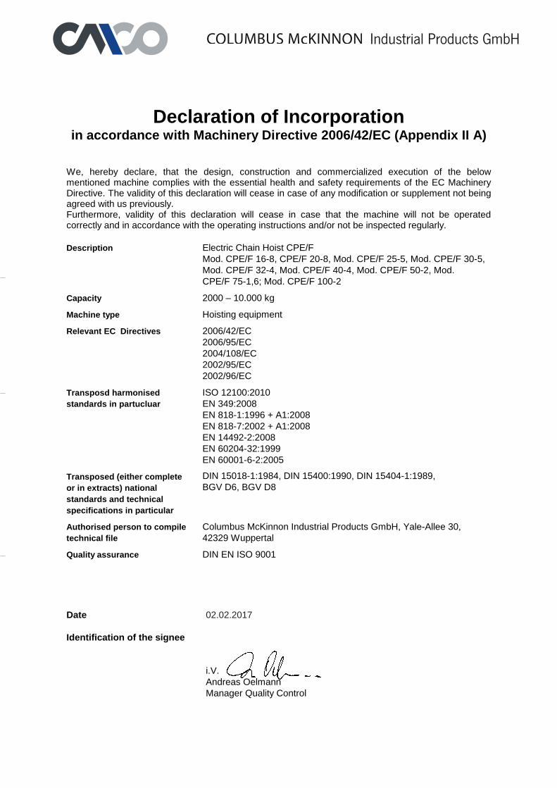
Declaration of Incorporation in accordance with Machinery Directive 2006/42/EC (Appendix II A)
We, hereby declare, that the design, construction and commercialized execution of the below mentioned machine complies with the essential health and safety requirements of the EC Machinery Directive. The validity of this declaration will cease in case of any modification or supplement not being agreed with us previously. Furthermore, validity of this declaration will cease in case that the machine will not be operated correctly and in accordance with the operating instructions and/or not be inspected regularly.
Description Electric Chain Hoist CPE/F
Mod. CPE/F 16-8, CPE/F 20-8, Mod. CPE/F 25-5, Mod. CPE/F 30-5,
Mod. CPE/F 32-4, Mod. CPE/F 40-4, Mod. CPE/F 50-2, Mod.
CPE/F 75-1,6; Mod. CPE/F 100-2
Capacity 2000 – 10.000 kg
Machine type Hoisting equipment
Relevant EC Directives 2006/42/EC
2006/95/EC
2004/108/EC
2002/95/EC
2002/96/EC
Transposd harmonised
standards in partucluar
ISO 12100:2010
EN 349:2008
EN 818-1:1996 + A1:2008
EN 818-7:2002 + A1:2008
EN 14492-2:2008
EN 60204-32:1999
EN 60001-6-2:2005
Transposed (either complete
or in extracts) national
standards and technical
specifications in particular
DIN 15018-1:1984, DIN 15400:1990, DIN 15404-1:1989,
BGV D6, BGV D8
Authorised person to compile
technical file
Columbus McKinnon Industrial Products GmbH, Yale-Allee 30,
42329 Wuppertal Quality assurance DIN EN ISO 9001
Date 02.02.2017
Identification of the signee
i.V.
Andreas Oelmann
Manager Quality Control
Industrial Products GmbH

*Diese Niederlassungen gehören der Matrix-Zertifizierung nach EN ISO 9001:ff an.
*These subsidiaries belong to the matrix-certification-system according to EN ISO 9001:ff.
Tech
nis
che Ä
nderu
ngen v
orb
ehalten. K
ein
e G
ewährleis
tung für
Dru
ckfe
hle
r oder
Irrt
üm
er
– S
ubje
ct to e
ngin
eering c
hanges
and im
pro
vem
ents
. N
o w
arr
anty
for
printing e
rrors
or
mis
take
s.
Reproduktionen, gleich welcher Art, nur mit schriftlicher Genehmigung der Columbus McKinnon Industrial Products GmbH!
Reproduction of any kind, only with written authorisation of Columbus McKinnon Industrial Products GmbH!
GermanyCOLUMBUS McKINNONIndustrial Products GmbH*Yale-Allee 30
42329 Wuppertal
Phone: 00 49 (0) 202/693 59-0
Web Site: www.cmco.eu
Web Site: www.yale.de
E-mail: [email protected]
COLUMBUS McKINNONEngineered Products GmbH*Am Silberpark 2-8
86438 Kissing
Phone: 00 49 (0) 8233 2121-800
Web Site: www.cmco.eu
Web Site: www.pfaff-silberblau.com
E-Mail: [email protected]
FranceCOLUMBUS McKINNON France SARL*Zone Industrielle des Forges
18108 Vierzon Cedex
Phone: 00 33 (0) 248/71 85 70
Fax: 00 33 (0) 248/75 30 55
Web Site: www.cmco-france.com
E-mail: [email protected]
United KingdomCOLUMBUS McKINNON Corporation Ltd.Knutsford Way, Sealand Industrial Estate
Chester CH1 4NZ
Phone: 00 44 (0) 1244 375375
Fax: 00 44 (0) 1244 377403
Web Site: www.cmco.eu
E-mail: [email protected]
ItalyCOLUMBUS McKINNON Italia S.r.l.Via P. Picasso, 32
20025 Legnano (MI)
Phone: 00 39 (0) 331/57 63 29
Fax: 00 39 (0) 331/46 82 62
Web Site: www.cmco.eu
E-mail: [email protected]
NetherlandsCOLUMBUS McKINNON Benelux B.V.*Grotenoord 30
3341 LT Hendrik Ido Ambacht
Phone: 00 31 (0) 78/6 82 59 67
Fax: 00 31 (0) 78/6 82 59 74
Web Site: www.cmco.eu
E-mail: [email protected]
South AfricaCMCO Material Handling (Pty) Ltd.*P.O. Box 15557
Westmead, 3608
Phone: 00 27 (0) 31/700 43 88
Fax: 00 27 (0) 31/700 45 12
Web Site: www.yale.co.za
E-mail: [email protected]
Yale Engineering Products (Pty) Ltd.12 Laser Park Square, 34 Zeiss Rd.
Laser Park Industrial Area, Honeydew
Phone: 00 27 (0) 11/794 29 10
Fax: 00 27 (0) 11/794 35 60
Web Site: www.yalejhb.co.za
E-mail: [email protected]
Yale Lifting Solutions (Pty) Ltd.P.O. Box 592
Magaliesburg, 1791
Phone: 00 27 (0) 14/577 26 07
Fax: 00 27 (0) 14/577 35 34
Web Site: www.yale.co.za
E-mail: [email protected]
TurkeyCOLUMBUS McKINNONKaldırma Ekip. San. ve Tic. Ltd. Şti.Davutpaşa Caddesi Emintaş
Davutpaşa Matbaacılar Sitesi No. 103/233-234
34010. Topkapı-İstanbul
Phone: 00 90 (212) 210 7 555
Fax: 00 90 (212) 220 7 505
Web Site: www.cmco.eu
E-mail: [email protected]
HungaryCOLUMBUS McKINNON Hungary Kft.Vásárhelyi út 5. VI ép
8000 Székesfehérvár
Phone: 00 36 22 880 540
Fax: 00 36 22 880 503
Web Site: www.cmco.eu
E-mail: [email protected]
United Arab EmiratesCOLUMBUS McKINNONIndustrial Products ME FZEWarehouse No. FZSBD01
P.O. Box 261013
Jebel Ali Free Zone, Dubai, U.A.E.
Phone: 00 971 4 8807772
Fax: 00 971 4 8807773
Web Site: www.cmco.eu
E-mail: [email protected]
Northern Ireland & Republic of IrelandCOLUMBUS McKINNON Corporation Ltd.1A Ferguson Centre
57-59 Manse Road
Newtownabbey BT36 6RW
Northern Ireland
Phone: 00 44 (0) 2890 840697
Fax: 00 44 (0) 2890 343673
Web Site: www.cmco.eu
E-mail: [email protected]
AustriaCOLUMBUS McKINNON Austria GmbH*Gewerbepark, Wiener Straße 132a
2511 Pfaffstätten
Phone: 00 43 (0) 22 52/4 60 66-0
Fax: 00 43 (0) 22 52/4 60 66-22
Web Site: www.cmco.at
E-mail: [email protected]
PolandCOLUMBUS McKINNON Polska Sp. z o.o.ul. Owsiana 14
62-064 PLEWISKA
Phone: 00 48 (0) 61 6 56 66 22
Fax: 00 48 (0) 61 6 56 66 88
Web Site: www.pfaff.info.pl
E-Mail: [email protected]
RussiaCOLUMBUS McKINNON Russia LLCul. Marshala Govorova 35/2
198095 St. Petersburg
Phone: 007 (812) 322 68 38
Fax: 007 (812) 322 68 38
Web Site: www.cmco.ru
E-mail: [email protected]
SwitzerlandCOLUMBUS McKINNON Switzerland AGDällikerstraße 25
8107 Buchs ZH
Phone: 00 41 (0) 44 8 51 55 77
Fax: 00 41 (0) 44 8 51 55 88
Web Site: www.cmco.ch
E-mail: [email protected]
Spain & PortugalCOLUMBUS McKINNON Ibérica S.L.U.Ctra. de la Esclusa, 21 acc. A
41011 Sevilla
Phone: 00 34 954 29 89 40
Fax: 00 34 954 29 89 42
Web Site: www.yaleiberica.com
E-mail: [email protected]
![Elektrokettenzüge von LIFTKET · Modell Triebwerksgruppe Hubwerk FEM 9.511 Triebwerksgruppe Kette FEM 9.511 Einschaltdauer [%] / Schaltungen [S/h] Leistung Hubmotor bei 50 Hz [kW]](https://img.pdfslide.net/doc/110x75/5b37dc867f8b9aad388ed248/elektrokettenzuege-von-liftket-modell-triebwerksgruppe-hubwerk-fem-9511-triebwerksgruppe.jpg)