Embed Size (px)
Citation preview
Electric Circuits
AP Physics B
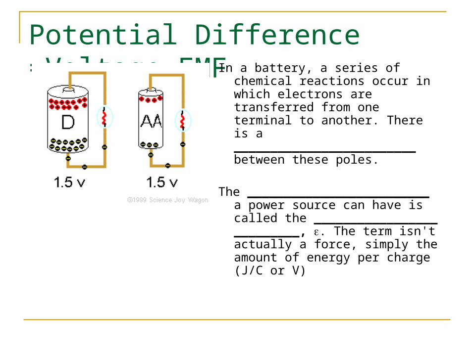
Potential Difference =Voltage=EMFIn a battery, a series of chemical
reactions occur in which electrons are transferred from one terminal to another. There is a _________________________ between these poles.
The _________________________ a power source can have is called the _________________ _________, . The term isn't actually a force, simply the amount of energy per charge (J/C or V)
A Basic CircuitAll electric circuits have three main parts
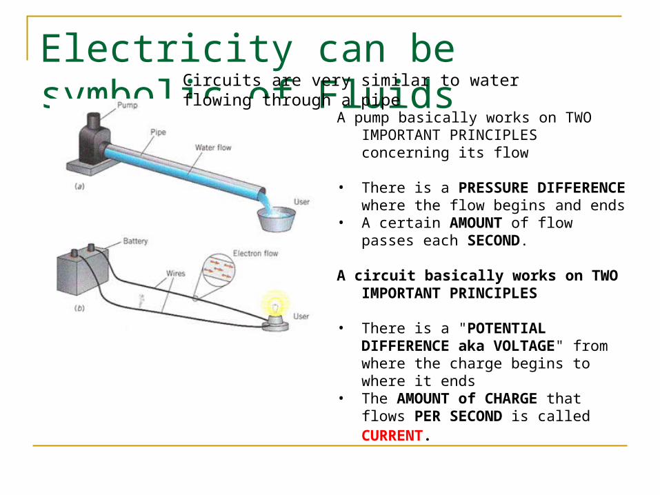
Electricity can be symbolic of Fluids Circuits are very similar to water flowing through a pipe
A pump basically works on TWO IMPORTANT PRINCIPLES concerning its flow
• There is a PRESSURE DIFFERENCE where the flow begins and ends
• A certain AMOUNT of flow passes each SECOND.
A circuit basically works on TWO IMPORTANT PRINCIPLES
• There is a "POTENTIAL DIFFERENCE aka VOLTAGE" from where the charge begins to where it ends
• The AMOUNT of CHARGE that flows PER SECOND is called CURRENT.
CurrentCurrent is defined as the rate at which charge
flows through a surface.
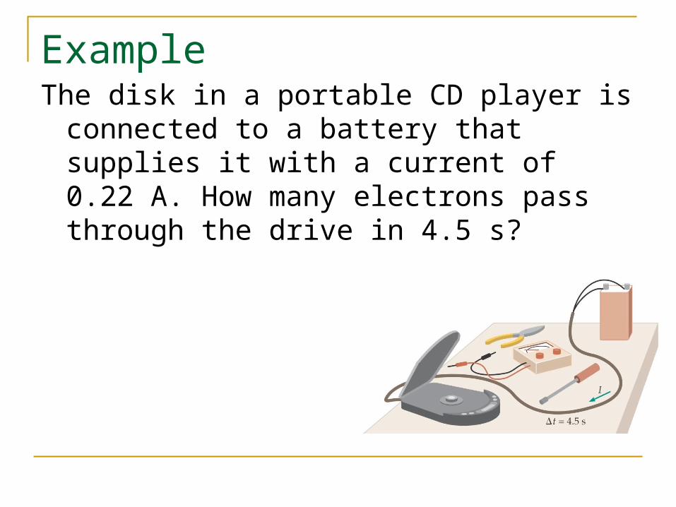
ExampleThe disk in a portable CD player is connected
to a battery that supplies it with a current of 0.22 A. How many electrons pass through the drive in 4.5 s?
There are 2 types of Current
Conventional vs. Actual Current Scientists used to believe that positive charges
moved through metal wires, but now we know that electrons (negative charges) are what moves.
Conventional current is the hypothetical flow of positive charges that would have the same effect in the circuit as the movement of negative charges that actually does occur.
The direction of conventional current is always from a point of higher potential (positive terminal) toward a point of lower potential (negative terminal).

Ohm’s Law
Voltage vs. Current
0
1
2
3
4
5
6
7
8
9
10
0 0.2 0.4 0.6 0.8 1
Current(Amps)
Vo
ltag
e(V
)
Voltage(V)
R= resista
nce = slo
pe
ExampleA potential difference of 24 V is applied to a
150 Ω resistor. How much current flows through the resistor?
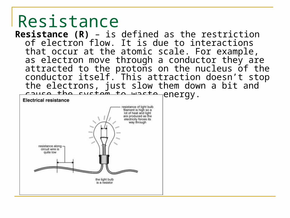
ResistanceResistance (R) – is defined as the restriction of electron
flow. It is due to interactions that occur at the atomic scale. For example, as electron move through a conductor they are attracted to the protons on the nucleus of the conductor itself. This attraction doesn’t stop the electrons, just slow them down a bit and cause the system to waste energy.
Resistance depends on…
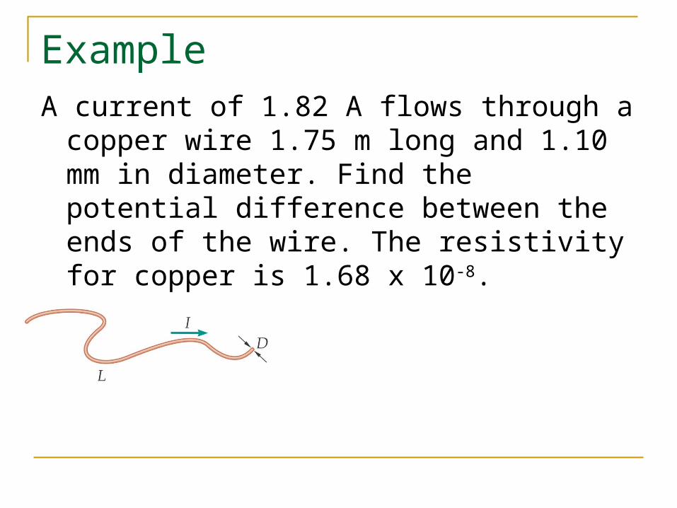
ExampleA current of 1.82 A flows through a copper wire
1.75 m long and 1.10 mm in diameter. Find the potential difference between the ends of the wire. The resistivity for copper is 1.68 x 10⁻⁸.
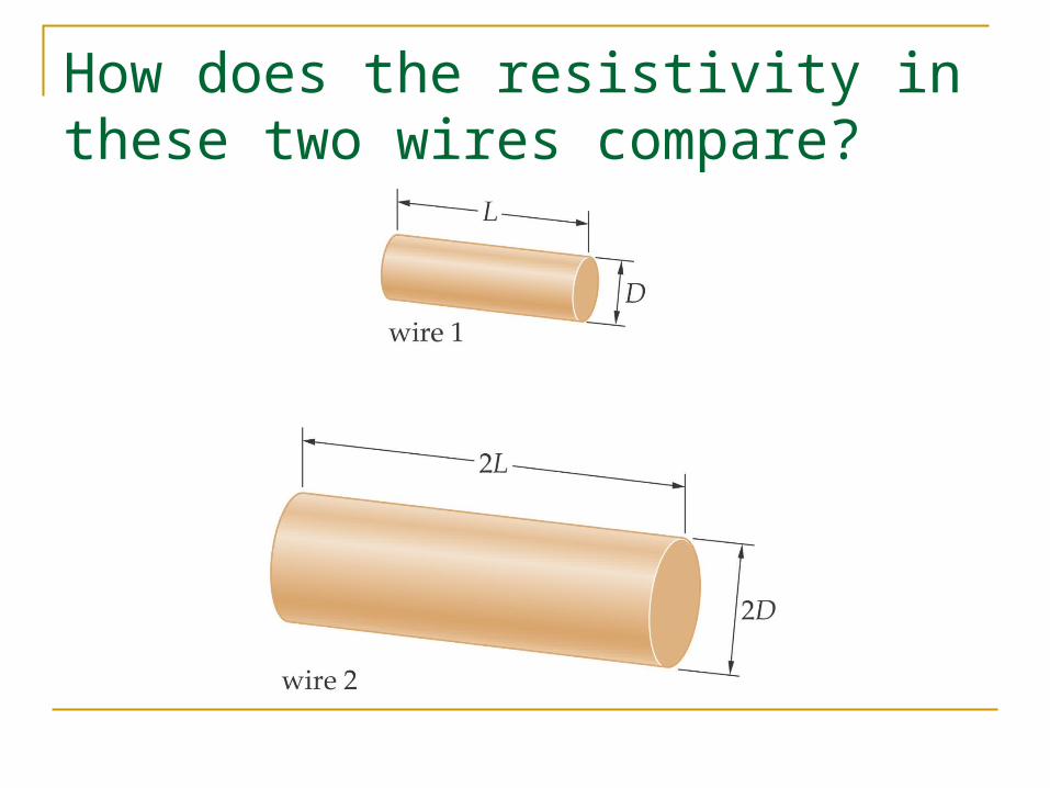
How does the resistivity in these two wires compare?

Electrical POWERWe have already learned that POWER is the rate at which work
(energy) is done. Circuits that are a prime example of this as batteries only last for a certain amount of time AND we get charged an energy bill each month based on the amount of energy we used over the course of a month…aka POWER.
POWERIt is interesting to see how certain electrical
variables can be used to get POWER. Let’s take Voltage and Current for example.
Other useful power formulas
These formulas can also be used! They are simply derivations of the POWER formula with different versions of Ohm's law substituted in.

Also.. Power is measured in watts [1 watt = 1 J/sec]. This
quantity is CONSERVED in circuits; that is, the power supplied by the battery must be equal to the power consumed by all of the resistors in the circuit.
Sometimes problems will ask you to calculate power
by asking for "the rate at which heat [i.e. energy] is dissipated through a circuit element."
Rearranging the definition gives us another often used expression,
Pt = Energy…in this case “Energy” refers to energy dissipated

ExampleA handheld electric fan operates on a 3.00 V
battery. If the power generated by the fan is 2.24 W, what is the current supplied by the battery?
Schematic SymbolsBefore you begin to understand circuits you need to be able to
draw what they look like using a set of standard symbols understood anywhere in the world

The Voltmeter and AmmeterThe voltmeter and ammeter cannot be just placed anywhere in the circuit. They must be used according to their DEFINITION.
Since a voltmeter measures voltage or POTENTIAL DIFFERENCE it must be placed ACROSS the device you want to measure. That way you can measure the CHANGE on either side of the device.
Voltmeter is drawn ACROSS the resistor
Since the ammeter measures the current or FLOW it must be placed in such a way as the charges go THROUGH the device.
Current goes THROUGH the ammeter

Simple CircuitWhen you are drawing a
circuit it may be a wise thing to start by drawing the battery first, then follow along the loop (closed) starting with positive and drawing what you see.
Ways to Wire CircuitsThere are 2 basic ways to wire a circuit. Keep in
mind that a resistor could be ANYTHING ( bulb, toaster, ceramic material…etc)
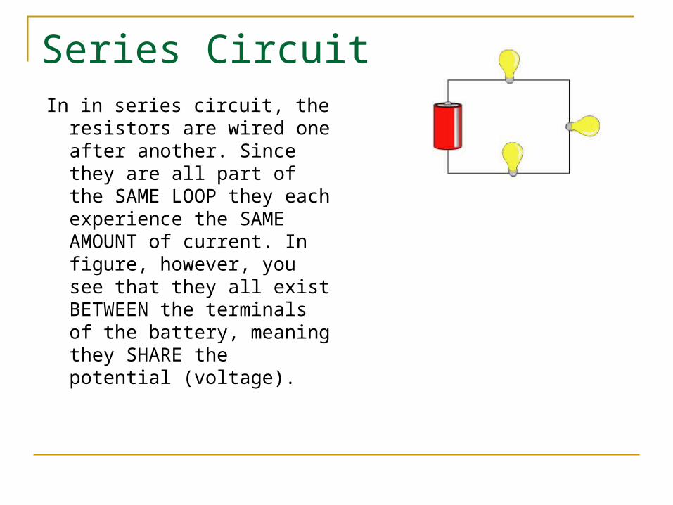
Series CircuitIn in series circuit, the resistors
are wired one after another. Since they are all part of the SAME LOOP they each experience the SAME AMOUNT of current. In figure, however, you see that they all exist BETWEEN the terminals of the battery, meaning they SHARE the potential (voltage).
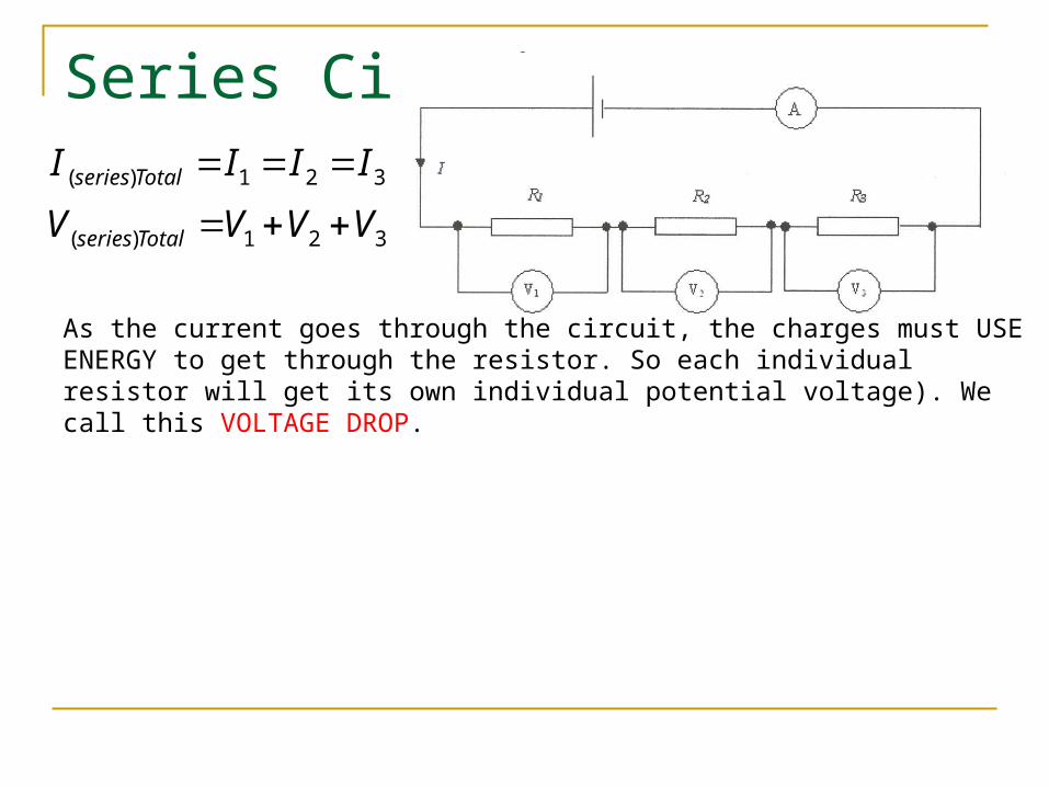
Series Circuit
321)(
321)(
VVVV
IIII
Totalseries
Totalseries
As the current goes through the circuit, the charges must USE ENERGY to get through the resistor. So each individual resistor will get its own individual potential voltage). We call this VOLTAGE DROP.
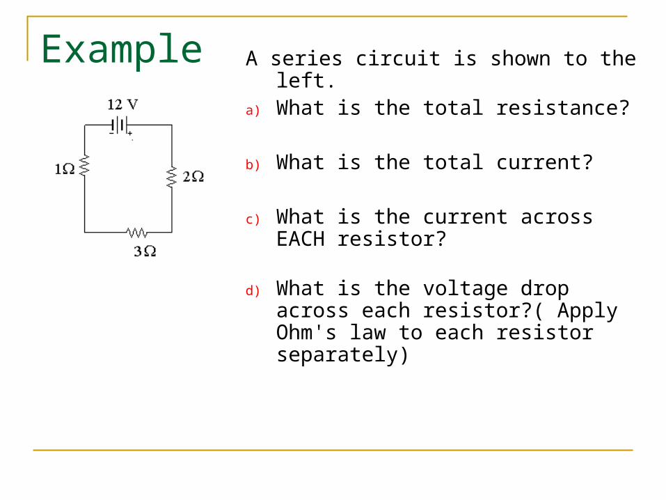
Example A series circuit is shown to the left. a) What is the total resistance?
b) What is the total current?
c) What is the current across EACH resistor?
d) What is the voltage drop across each resistor?( Apply Ohm's law to each resistor separately)

Parallel CircuitIn a parallel circuit, we have
multiple loops. So the current splits up among the loops with the individual loop currents adding to the total current
It is important to understand that parallel circuits will all have some position where the current splits and comes back together. We call these JUNCTIONS.
The current going IN to a junction will always equal the current going OUT of a junction.
Junctions
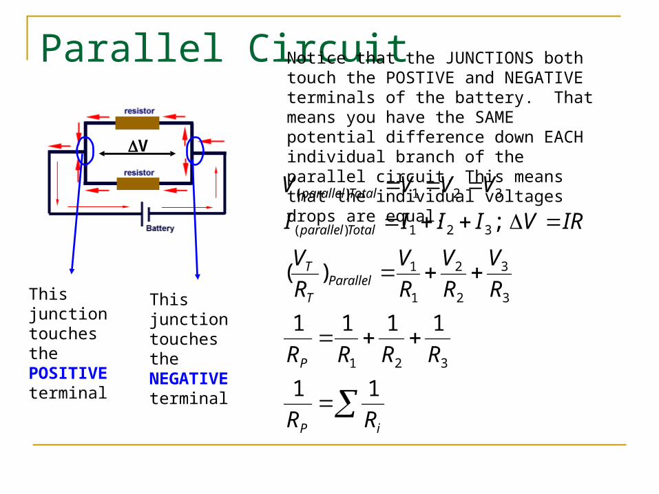
Parallel CircuitNotice that the JUNCTIONS both touch the POSTIVE and NEGATIVE terminals of the battery. That means you have the SAME potential difference down EACH individual branch of the parallel circuit. This means that the individual voltages drops are equal.
This junction touches the POSITIVE terminal
This junction touches the NEGATIVE terminal
V
iP
P
ParallelT
T
Totalparallel
Totalparallel
RR
RRRR
R
V
R
V
R
V
R
V
IRVIIII
VVVV
11
1111
)(
;
321
3
3
2
2
1
1
321)(
321)(
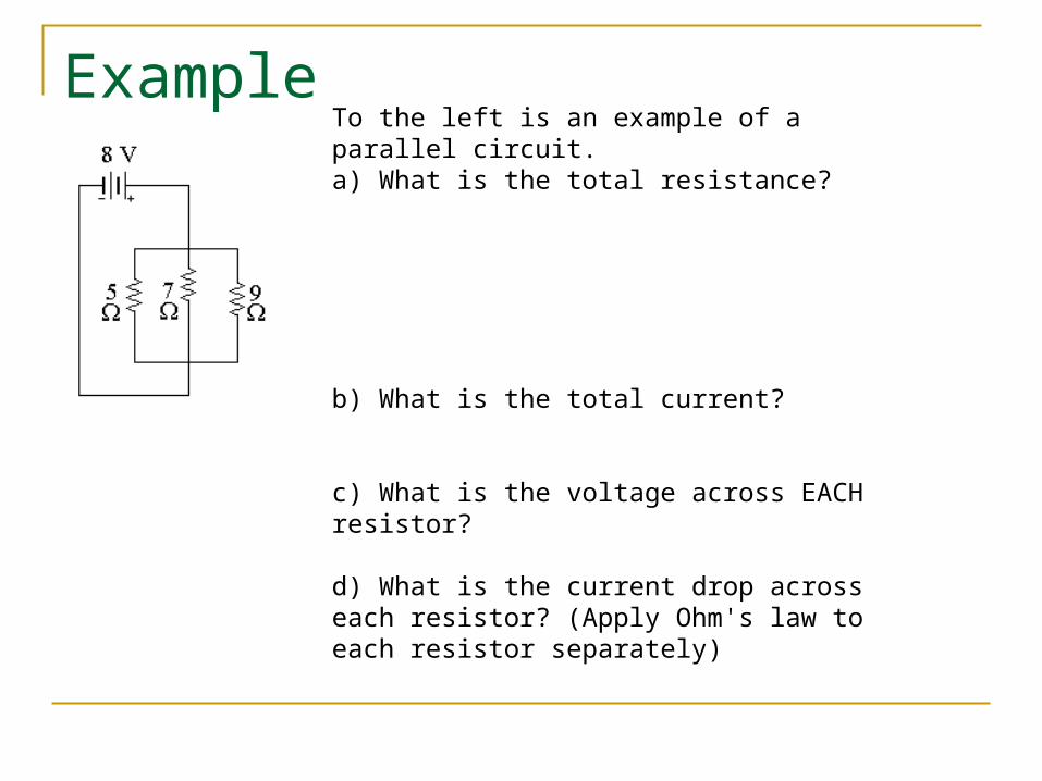
ExampleTo the left is an example of a parallel circuit. a) What is the total resistance?
b) What is the total current?
c) What is the voltage across EACH resistor? d) What is the current drop across each resistor? (Apply Ohm's law to each resistor separately)
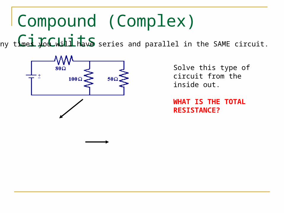
Compound (Complex) CircuitsMany times you will have series and parallel in the SAME circuit.
Solve this type of circuit from the inside out.
WHAT IS THE TOTAL RESISTANCE?
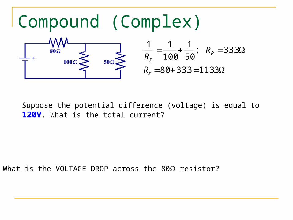
Compound (Complex) Circuits
3.1133.3380
3.33;50
1
100
11
s
PP
R
RR
Suppose the potential difference (voltage) is equal to 120V. What is the total current?
What is the VOLTAGE DROP across the 80 resistor?

Compound (Complex) Circuits
AI
VV
AI
VV
R
T
T
T
06.1
8.84
06.1
120
3.113
80
80
What is the VOLTAGE DROP across the 100 and 50 resistor?
What is the current across the 100 and 50 resistor?
Internal Resistance
This is resistance within an electrical device such as a battery or generator.
This resistance causes the actual voltage between the terminals to drop below the maximum value specified by the battery’s emf.
The actual voltage between the terminals of a battery is known as terminal voltage. Predictably, we will often ignore the internal resistance.
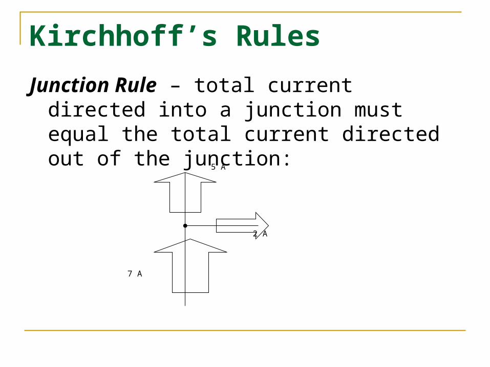
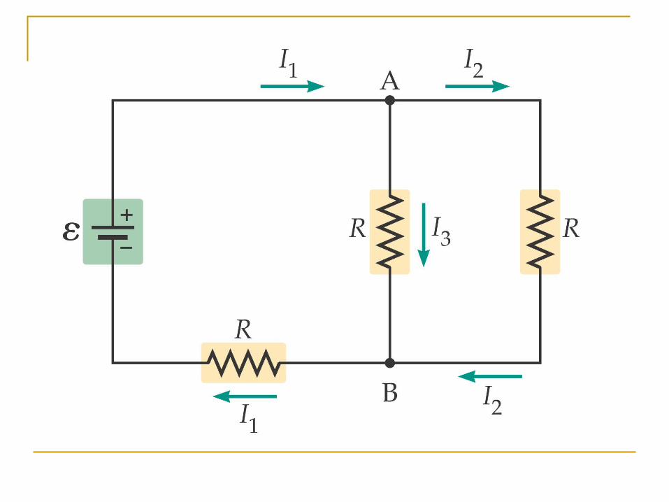
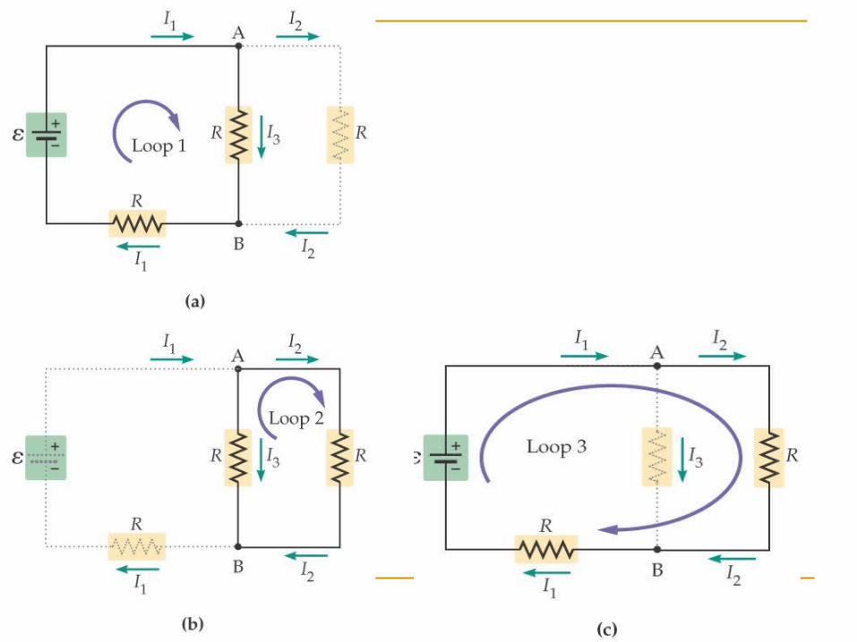
Kirchhoff’s Rules
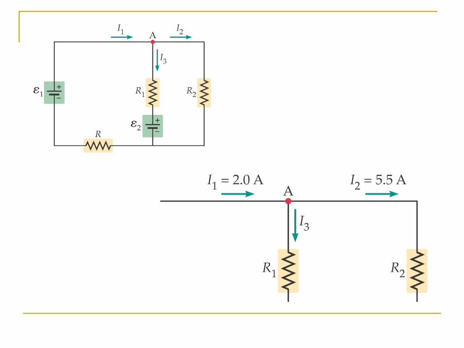
Junction Rule – total current directed into a junction must equal the total current directed out of the junction:
5 A
2 A
7 A
Kirchhoff’s Rules (cont.) Loop Rule – for a closed circuit loop, the total of all the potential
rises is the same as the total of all the potential drops. (in general, emf sources cause potential rises; resistors cause potential drops)
The rules for assigning SIGNS to the voltage changes across a resistor in a closed loop for Kirchhoff's loop rule are: voltage drop (-) if the direction of the current agrees with the
direction of the loop. voltage rise (+) if the direction of the current opposes the
direction of the loop. The rules for assigning SIGNS to the voltage changes across a
battery in a closed loop for Kirchoff’s loop rule are: voltage drop V = -ε if the direction of the loop crosses a battery
from + to - (high to low ) voltage rise V = +ε if the direction of the loop crosses a battery
from - to + (low to high)
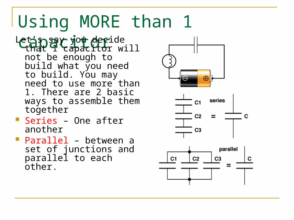
Using MORE than 1 capacitorLet’s say you decide that 1
capacitor will not be enough to build what you need to build. You may need to use more than 1. There are 2 basic ways to assemble them together
Series – One after another
Parallel – between a set of junctions and parallel to each other.
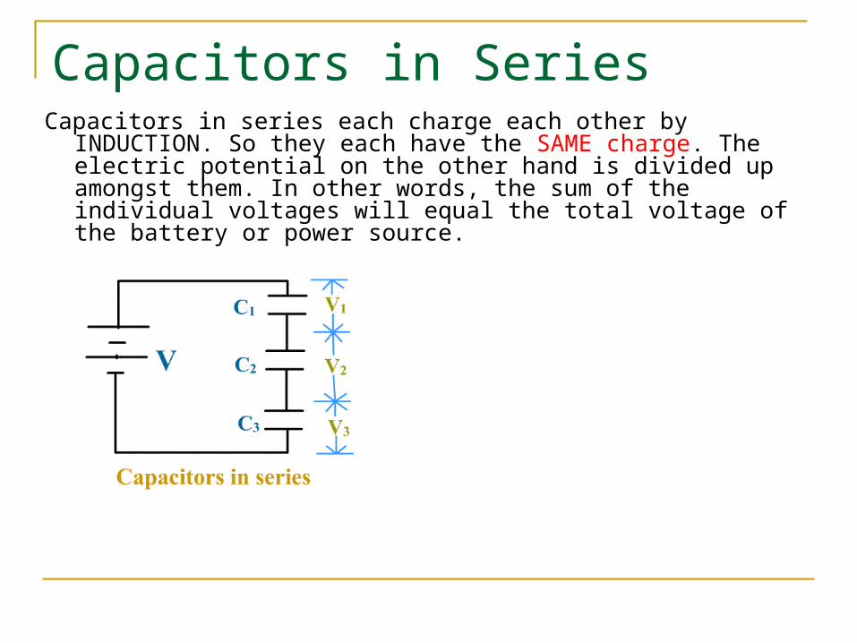
Capacitors in SeriesCapacitors in series each charge each other by INDUCTION. So
they each have the SAME charge. The electric potential on the other hand is divided up amongst them. In other words, the sum of the individual voltages will equal the total voltage of the battery or power source.
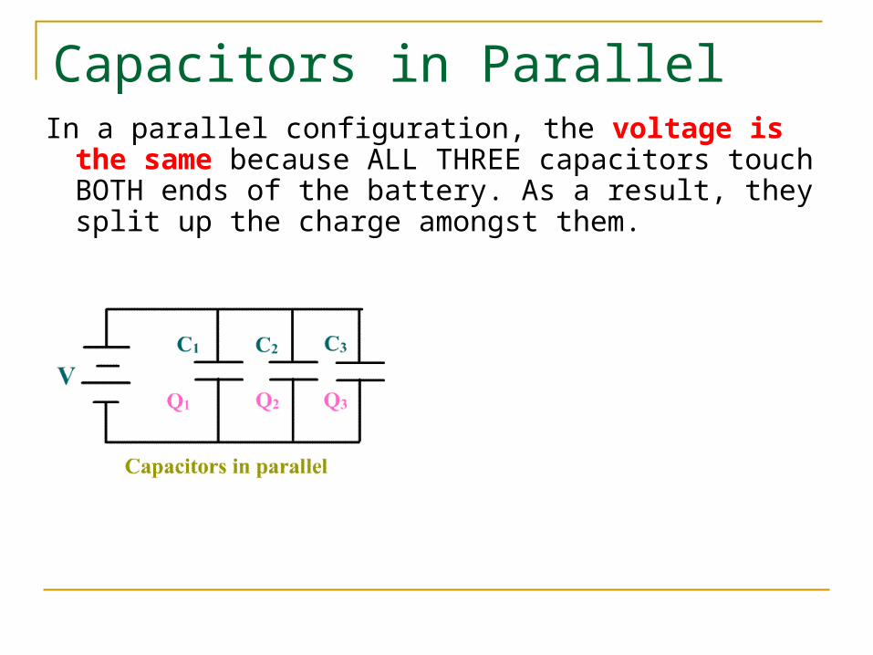
Capacitors in ParallelIn a parallel configuration, the voltage is the same
because ALL THREE capacitors touch BOTH ends of the battery. As a result, they split up the charge amongst them.
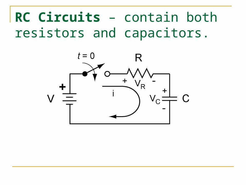
RC Circuits – contain both resistors and capacitors.
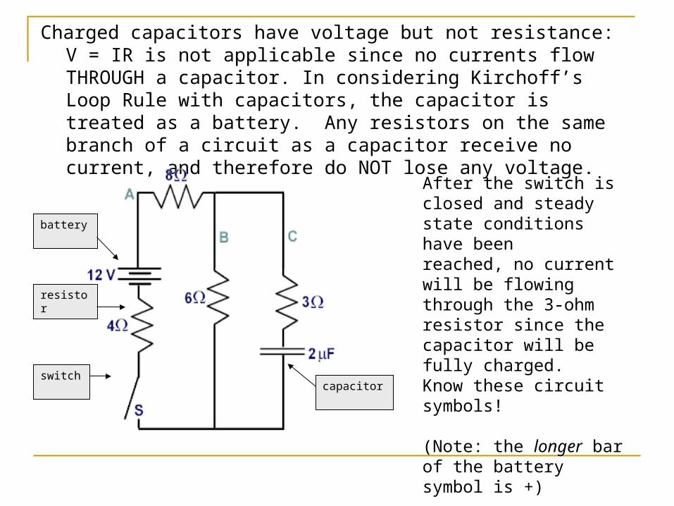
Charged capacitors have voltage but not resistance: V = IR is not applicable since no currents flow THROUGH a capacitor. In considering Kirchoff’s Loop Rule with capacitors, the capacitor is treated as a battery. Any resistors on the same branch of a circuit as a capacitor receive no current, and therefore do NOT lose any voltage.
switch
resistor
battery
capacitor
After the switch is closed and steady state conditions have been reached, no current will be flowing through the 3-ohm resistor since the capacitor will be fully charged.Know these circuit symbols!
(Note: the longer bar of the battery symbol is +)