Embed Size (px)
Citation preview

Electric Double Layer Capacitors
Products CatalogProducts Catalog
2018.3 http://industrial.panasonic.com/ww/products/capacitors/edlc
2018
Gold Capacitors

Design and specifications are each subject to change without notice. Ask factory for the current technical specifications before purchase and/or use.
Should a safety concern arise regarding this product, please be sure to contact us immediately.
——— Notices ———
■ Applicable Laws and Regulations
● This product complies with the RoHS Directive (Restriction of the use of certain Hazardous substances in electrical and electronic equipment (DIRECTIVE 2011/65/EU).
● No Ozone Depleting Chemicals(ODC's), controlled under the Montreal Protocol Agreement, are used in producing this product.
● We do not PBBs or PBDEs as brominated flame retardants.
● Export procedure which followed export related regulations, such as foreign exchange and a foreign trade method, on the occasion of export of this product Thank you for your consideration.
■ Limited applications
● This capacitor is designed to be used for electronics circuits such as audio/visual equipment, home appliances, computers and other office equipment, optical equipment, measuring equipment.
● High reliability and safety are required [ be / a possibility that incorrect operation of this product may do harm to a human life or property ] more. When use is considered by the use, the delivery specifications which suited
the use separately need to be exchanged.
——— Items to be observed ———
● This specification guarantees the quality and performance of the product as individual components.
Before use, check and evaluate their compatibility with installed in your products.
● Do not use the products beyond the specifications described in this document.
■ For specifi cations
● Install the following systems for a failsafe design to ensure safety if these products are to be used in equipment where a defect in these products may cause the loss of human life or other signification damage,
such as damage to vehicles (automobile, train, vessel), traffic lights, medical equipment, aerospace equipment,
electric heating appliances, combustion/ gas equipment, rotating rotating equipment, and disaster/crime
prevention equipment.
· The system is equipped with a protection circuit and protection device.
· The system is equipped with a redundant circuit or other system to prevent an unsafe status in the event of
a single fault.
■ Conditions of use
● Before using the products, carefully check the effects on their quality and performance, and determined whether or not they can be used. These products are designed and manufactured for general-purpose and
standard use in general electronic equipment. These products are not intended for use in the following special
conditions.
(1) In liquid, such as Water, Oil, Chemicals, or Organic solvent.
(2) In direct sunlight, outdoors, or in dust.
(3) In vapor, such as dew condensation water of resistive element, or water leakage, salty air, or air with a
high concentration corrosive gas, such as Cl2, H2S, NH3, SO2, or NOx.
(4) In an environment where strong static electricity or electromagnetic waves exist.
(5) Mounting or placing heat-generating components or inflammables, such as vinyl-coated wires, near
these products.
(6) Sealing or coating of these products or a printed circuit board on which these products are mounted,
with resin and other material.
(7) Using resolvent, water or water-soluble cleaner for flux cleaning agent after soldering. (In particular,
when using water or a water-soluble cleaning agent, be careful not to leave water residues)
(8) Using in the atmosphere which strays Acid or alkaline.
(9) Using in the atmosphere which there are excessive vibration and shock.
● Please arrange circuit design for preventing impulse or transitional voltage. Do not apply voltage, which exceeds the full rated voltage when the capacitors receive impulse voltage,
instantaneous high voltage, high pulse voltage etc.
● Our products there is a product are using an electrolyte solution. Therefore, misuse can result in rapid deterioration of characteristics and functions of each product. Electrolyte leakage damages printed circuit and
affects performance, characteristics, and functions of customer system.
Nov. 201500

Design and specifications are each subject to change without notice. Ask factory for the current technical specifications before purchase and/or use.
Should a safety concern arise regarding this product, please be sure to contact us immediately.
Electric Double Layer Capacitors (Gold Capacitor)
Application Guidelines (Gold Capacitor)1. Circuit design
1.1 Product LifeThe life of an electric double layer capacitor is limited. Its capacitance will decrease and its internal resistance will increase over time.The life of a capacitor greatly depends on the ambient temperature, humidity, applied voltage and discharging currents. Capacitor life can be extended when these parameters are set well below the ratings.The guaranteed durability of electric double-layer capacitors is between 1000 hours at 70 °C and 6000 hours at 85 °C. depending on product series. Generally, it is 1000 hours at 70 °C. The life of the capacitor is guaranteed to be 16000 hours at a normal temperature (30 °C) by applying the acceleration double for every 10 °C. Please choose the product that is suitable for the reliability that you need.If your application incorporates this capacitor over a long period of time, then check it periodically and replace it when necessary.
1.2 Polarity and voltage Capacitors have polarities.
Do not apply a reverse or AC voltage. If a reversed voltage is applied to a capacitor for a long period of time, then its life will be reduced and critical failures such as electrolyte leakage might occur. Do not apply an over-voltage (a voltage exceeding the rated voltage).If voltage exceeding the rating is applied to the capacitor for a long time, then its life will be reduced and critical failures such as electrolyte leakage or physical damage due to gas generated by electrochemical reaction or explosion might occur.
1.3 Circuits though which ripple currents pass When using a capacitor in a circuit through which ripple currents pass, please note following matters.
(1) The internal resistance of electric double-layer capacitors is higher than that of electrolytic capacitors. Electric double-layer capacitors may generate heat due to ripple currents.
(2) Please do not exceed the maximum operating voltage when the voltage changes from ripple.(3) Because internal resistance is high, the gold capacitor is not basically suitable for the absorption of ripple
current.
1.4 Ambient temperature and product lifeCapacitor life is affected by usage temperatures. Generally speaking, capacitor life is approximately doubled
when the temperature is decreased by 10 °C. Therefore, lower the usage temperature as much as possible. Using capacitors beyond the guaranteed range might cause rapid deterioration of their characteristics and cause them to break down. The temperature referred to here includes the ambient temperature within the equipment, the heat produced by heat generating devices (power transistor, resistors, etc.), self-heating due to ripple currents, etc. Take all of these factors into consideration when checking the capacitor’s temperature.Do not place any heat generating devices on the back of the capacitors. Life acceleration can be calculated with the following equation :
L2 = L1×2( )
L1 : Life at temperature T1 °C (h)L2 : Life at temperature T2 °C (h)T1 : Category s upper limit temperatureT2 : Ambient temperature to calculate the life + heat generation due to ripple current (°C)
✽ Humidity also affects the capacitor’s life. When using capacitors outside the following conditions, please contact us. A temperature at +55 °C and a relative humidity of 90 % to 95% for 500 hours.
✽ The result that a very long term backup can be expected in calculation might be obtained by use conditions. However, please consider checking regularly and exchanging it when using it for the set that long-term reliability is basically demanded from the Gold Capacitor.
1.5 Voltage dropPay particular attention to the instantaneous working current and the voltage drop due to the capacitor’s
internal resistance when used in backup mode. The discharging current level is different depending on the
capacitor’s internal resistance. Use a capacitor with a discharging current below what is specified by the
corresponding capacitor.
Series
Max. Discharging Current
0.047 F or less 0.1 F to 0.33 F 0.47 F to 1.5 F 3.3 F to 4.7 F 10 F to 100 F
SG/SD/SE/NF/F 200 µA 300 µA 1 mA — —
RF (–40 °C, –25 °C) — 300 µA, 3 mA 1 mA, 20 mA — —
LF (–40 °C) — — 1 mA — —
RG (–40 °C, –25 °C) — 300 µA, 1 mA 1 mA, 20 mA — —
T1-T2
10
Jan. 201705

Design and specifications are each subject to change without notice. Ask factory for the current technical specifications before purchase and/or use.
Should a safety concern arise regarding this product, please be sure to contact us immediately.
Electric Double Layer Capacitors (Gold Capacitor)
260
240
220
0 2 4 6 8
General specifide ange
Recommended range
Dipping time (s)
Sold
er
bath
tem
pera
ture
(°C
)
Pre-heating temperature : 110 °C or under(on the surface of circuit)
: 100 °C or under(on the surface of capacitor)
Pre-heating time : 60 seconds or under
Board thickness : 0.8 mm or more
1.6 Series connectionWhen connecting capacitors in series, add a bleeder resistor in parallel with each capacitor by taking the leakage current into consideration so that the balance of voltages is not disrupted.
✽ Please present use condition about HZ/HW/HL series, and please contact us.
1.7 Electrolyte is used in the productsElectrolyte is used in the capacitors. Electrolyte leakage will damage printed circuit boards and can affect their performance, characteristics, and functions.
1.8 External sleeveThe external sleeve is not electrical insulation, and thus capacitors should not be used in an environment that requires electrical insulation. The sleeve is covered only for showing ratings.
2. Mounting2.1 Heat stress at the soldering
When soldering a capacitor to a printed circuit board, excessive heat stress could cause the deterioration of the capacitor’s electrical characteristics. For example the integrity of the seal can be compromised causing the electrolyte to leak, and short circuits could occur in addition to and failure of the appearance. Please observe the following guidelines.(1) Manual soldering Do not touch the capacitor body with a soldering iron. Solder the capacitor using a soldering tip temperature of
350 °C or less for 4 seconds or less. Solder a the capacitor three times or less at intervals of 15 seconds or more.(2) Flow soldering
1) Do not dip the body of the products into a soldering bath.
2) Keep the product’s surface temperature at or below 100 °C for no more than 60 seconds (the peak 105 °C) when soldering. Please refer to the chart at right to set soldering temperature and time. It is recommended to check the product temperature before you use.
3) The terminals of the NF/F/RF/LF type are designed so the bottom of the product floats from the PWB. This is to protect against heat stress during soldering. Do not touch the bottom of the product directly to the PWB.
(3) Other heat stress1) Keep the product’s surface temperature
at or below 100 °C for no more than 60 seconds (the peak 105 °C) when applying heat to bake the PWB or fixing resin, etc.The capacitor voltage must be 0.3 V or less.
2) Do not use a product more than once after it has been mounted on the PWB. Excessive heat stress is applied when detaching it from the PWB. Please observe “(1) Manual soldering” when you adjusting it.
3) Be sure that excessive heat stress is not applied to the Gold capacitor when other parts in its surroundings of the Gold capacitor are detached or adjusted.
(4) Others1) The lead wires and terminals are plated for solderability. Rasping or filing lead wires or terminals
might damage the plating layer and degrade the solderability.2) Do not apply a large mechanical force to the lead wires or terminals. Otherwise, they may break or
come off or the capacitor characteristics may be damaged.3) There is a possibility that the sealing performance of the product is deteriorated if a coating material
that contains an organic solvent is used.
2.2 Circuit DesignDo not set wiring pattern directly under the mounted capacitor, and pass between terminals. If the
electrolyte leaks, short circuit might occur and tracking or migrations are anticipated. If a capacitor is
directly touching a PWB, then the bottom of the capacitorand the circuit pattern may short-circuit. On PWBs,
blowing flux or solder may cause the capacitor’s external sleeve to break or shrink, potentially affecting the
internal structure. In addition, please refer to application guidelines for the aluminum electrolytic capacitor.
2.3 Residual voltageGold Capacitors can hold a large charge and could have residual voltage. Therefore, some electronic
components with a low withstand voltage, such as semi-conductors, might be damaged.
Jan. 201705

Design and specifications are each subject to change without notice. Ask factory for the current technical specifications before purchase and/or use.
Should a safety concern arise regarding this product, please be sure to contact us immediately.
Electric Double Layer Capacitors (Gold Capacitor)
2.4 Circuit board cleaningApply the following conditions for flux cleaning after soldering. (Excepted for NF/F/RF/LF series)
Please examine the SG/SD/RG series when washing is necessary.
Temperature : 60 °C or less
Duraiton : 5 minutes or less
Rinse sufficiently and dry the boards.
[Recommended cleaning solvents include]
Pine Alpha ST-100s, Sunelec B-12, DK be-clear CW-5790, Aqua Cleaner 210SEP, Cold Cleaner P3-375, Cllear-
th-ru 750H, Clean-thru 750L, Clean-thru 710M, Techno Cleaner219, Techno Care FRW-17, Techno Care FRW-1,
Techno Care FRV1
● Consult with us if you are using a solvent other than any of those listed above or Deionized water.
● The uses of ozone depleting cleaning agents is not recommended in the interest protecting the environment.
3. Precautions for using equipmentAvoid using mounting equipment in environments where :
(1) Capacitors are exposed to water, salt water or oil.
(2) Capacitors are exposed to direct sunlight.
(3) Capacitors are exposed to high temperature and humidity where water can condense on the capacitor surface.
(4) Capacitors are subject to various active gases.
(5) Capacitors are exposed to acidic or alkaline environments.
(6) Capacitors are subject to high-frequency induction.
(7)Capacitors are subject to excessive vibrations or mechanical impact.
A brown excretion might be caused around the sealing, depending on the conditions of use. This excretion is
insulation and does not. have influence on the electrical characteristics.
4. Maintenance PrecautionsPeriodically check capacitors used in industrial equipment. When checking and maintaining capacitors, turn off
the equipment and discharge the capacitors beforehand. Do not apply stress to the capacitor lead terminals.
Periodically check the following items.
1) Significant appearance abnormalities (deformation, electrolyte leakage, etc.)
2) Electrical characteristics (described in the catalog or delivery specifications)
If any abnormalities are found, then replace the capacitors or take appropriate actions.
5. Emergency proceduresIf the capacitors generate heat, then smoke may come out of the exterior resin. Under these conditions turn off
the equipment immediately and stop using it.
Do not place your face or hands close to the capacitor, burns might be caused.
6. StorageDo not store capacitors in a high-temperature or high-humidity environment. Store capacitors at a room
temperature of 5 to 35 °C and a relative humidity of 85 % or less. (Recommended storage term: 1year or less.)
Store capacitors in their packaging as long as possible. Avoid storing capacitors under the following conditions.
(1) Exposed to water, high temperatures or humidity, or when condensation can occurs.
(2) Exposed to oil or in environments filled with gaseous oil contents.
(3) Exposed to salt water or environments filled with saline substances.
(4) In environments filled with harmful gases
(hydrogen disulfide, sulfurous acid, nitrous acid, chlorine, bromine, bromomethane, etc.)
(5) In environments filled with harmful alkaline gases such as ammonia.
(6) Exposed to acid or alkaline solvents.
(7) Exposed to direct sunlight, ozone, ultraviolet or radial rays.
(8) Exposed to vibration or mechanical impact.
7. DiscardingDispose of capacitors as industrial waste. They are comprised of various metals and resin.
The precautions for the use of Electric Double Layer Capacitors (Gold Capacitors) follow the “Precautionary guidelines for the use of fixed Electric Double Layer Capacitors for electronic equipment”, RCR-2370C issued by EIAJ in July 2008. Please refer to the above guidelines for details.
Jan. 201705

Design and specifications are each subject to change without notice. Ask factory for the current technical specifications before purchase and/or use.
Should a safety concern arise regarding this product, please be sure to contact us immediately.
Electric Double Layer Capacitors (Gold Capacitor)
NEW
NEW
Standard
Miniaturized
Taped
85 °C 1000 hguaranteed
85 °C 2000 h guaranteed
NF5.5 V.DC
0.22 F to 1.5 F–40, –25 °C to +70 °C
F5.5 V.DC
0.1 F to 1.0 F–40, –25 °C to +85 °C
SE5.5 V.DC
0.22 F–40, –25 °C to +70 °C
SD5.5 V.DC
0.22 F to 0.33 F–40, –25 °C to +70 °C
SG5.5 V.DC
0.47 F to 1.5 F–40, –25 °C to +70 °C
RG3.6 V.DC
0.22 F to 1.5 F–40, –25 °C to +85 °C
RF5.5 V.DC
0.1 F to 1.0 F–40, –25 °C to +85 °C
Stacked coin type/Standard
Stacked coin type/High reliability
Radial lead type
Miniaturized/High voltage
High withstand voltage/Low resistance/High reliability (2000 h guaranteed)
HW2.3(2.1) V.DC 22 F to 70 F
< 0.1 Ω–25 °C ~ +70(60) °C
HL2.7 V.DC
50 F to 100 F< 0.01 Ω
–40 °C to +65 °C
HL (Miniaturized)
2.7 V.DC2.5 F to 7.5 F
< 0.03 Ω–40 °C to +70 °C
HZ2.5 V.DC
3.3 F to 10 F< 0.2 Ω
–25 °C to +70 °C
85 °C 6000 h guaranteed
LF5.5 V.DC
1.0 F–40 °C to +85 °C
Diagram
Jan. 201705

Electric Double Layer Capacitors ( Gold Capacitors )
Explanation of part numbers
Part number system
Product classification Max. operating voltage codeSeries code① Capacitance code
EEC F 104◇ Series:NF、F
1 figure 3 figures 3 figures3 figuresSuffix
0 ~1 figure
Series Code
RG (-25℃ to +85 ℃ :2000 h)RF (-25℃ to +85 ℃ :2000 h)SE (-25℃ to +70 ℃ :1000 h)SG (-25℃ to +70 ℃ :1000 h)F (-25℃ to +85 ℃ :1000 h)NF (-25℃ to +70 ℃ :1000 h)SD (-25℃ to +70 ℃ :1000 h)
RGRF SE S
①F ②H①F ②U①S ②D
Series Code
HZ (-25℃ to +70 ℃ :1000 h)HW (-25℃ to +60 ℃(+70℃) :1000 h)HL (-40℃ to +65 ℃ :2000 h)
HZHWHL
Suffix0 ~2 figures
Product classification3 figures
Series code2 figures
Max. operating voltage code2 figures
EEC RG 0V 224◇ Series:RG
Product classification Max. operating voltage codeSeries code Capacitance code
EEC S 5R5 474◇ Series:SG
Terminal style
Max. operating voltage code
Series code Capacitance code
EEC HZ 0E 335
1 figure 3 figures 3 figures3 figures
3 figures2 figures2 figures
Capacitance(F)
Code
3.34.7
1022305070
100
335475106226306506706107
3.65.55.5
Code
0.10.220.330.470.681.01.5
104224334474684105155
Capacitance(F)
CodeMax. operating
voltage(V.DC)
2.12.32.52.7
Code
◇ Series:HZ、HW、HL
0V0H5R5
0D0D0E0E
Product classification3 figures
*Terminal style(RG、SG、SD) V or H
Suffix0 ~1 figure
*Suffix (Series common)
N : Low temperature guarantee (-40℃ to )
【 Multilayer Coin Type 】
V U
Product classification Max. operating voltage codeSeries code
EEC RF 0H 1042 figures 2 figures3 figures
Suffix0 ~2 figures
◇ Series:RF、SE
◇ Series:SD
Product classification
Max. operating voltage codeSeries code① Capacitance code
EEC S 0H 2241 figure 2 figures 3 figures3 figures
Suffix0 ~1 figure
Series code②
D1 figure
Terminal style1 figure
Terminal style1 figure
5R5Series code②
1 figure
【 Wound Type 】
U
U
N
U
-
Capacitance code3 figures
Capacitance code3 figures
H
V
H
1 figureSuffix
0 ~1 figure
Max. operating voltage(V.DC)

Design and specifications are each subject to change without notice. Ask factory for the current technical specifications before purchase and/or use.
Should a safety concern arise regarding this product, please be sure to contact us immediately.
Electric Double Layer Capacitors (Gold Capacitor)
+–
f19.0±0.3
21.0
max.
1.0±0.1
5.0
±0.3
0.20±0.055.0±0.5
5.5±0.5
4.0
±0.3 20.5 Max.
Sleeve
20.0±0.5
f19.0±0.3
1.0±0.10.2±0.05
6.5
max
.3.
5±0.
3
10.0±0.5
0.2±0.05
3.0±
0.5
010
.5 m
ax.
11.5 max.
6.0
max
.
0.8±0.05(1.7)
Sleeve
0.8±0.05
(1.7)
3.0
±0.5
11.5
max.
10.5 max.
0.2±0.05
5.0 max.
5.0±0.8
● Endurance : +85 °C 2000 h● Category temperature range : –40 °C to +85 °C● RoHS compliant
● Backup of data/RTC of base station, electronic meter, and industrial equipment
Stacked Coin Type
Series : RG Low temperature assured product
(Unit : mm)
Features
Recommended applications
Specifi cations
Dimensions in mm(not to scale)
Characteristics list
Do not use refl ow soldering. (IR, Atmospherheating methods, etc.) Please refer to the page of “Application guidelines”.
( ) : Please use V or H to indicate terminal type.
The recommended discharge current is a reference value. Please design your equipment(circuit) in consideration of IR dorop.
RG series 1.0, 1.5(F)
Terminal : V Terminal : H
RG series 0.22(F)
Terminal : V Terminal : H
Maximum
operating
voltage
(V.DC)
Capacitance
(F)
Capacitance
tolerance
(F)
Internal resistance
(Initial specifi ed value)(Ω) at 1 kHz
Recommended
discharge current
(mA)
Parts number
Mass
(Reference value)
(g)
Min.
packaging
q'ty
(pcs)
3.6
0.22 0.176 to 0.396 < 50 300 µA or less EECRG0V224( )N 1.0 200
1.0 0.8 to 1.8 < 20 1 mA or less EECRG0V105( )N 4.1 100
1.5 1.2 to 2.7 < 20 1 mA or less EECRG0V155( )N 4.2 100
Category temp. range –40 °C to +85 °C
Maximum operating voltage 3.6 V.DC
Nominal capacitance 0.22 F 1.0 F, 1.5 F
Characteristics at
low temperature
Capacitance change ±30 % of initial measured value at +20 °C (at –40 °C)
Internal resistance < 7 times of initial measured value at +20 °C (at –40 °C)
Endurance
After 2000 hours application of maximum operating voltage at +85 °C
Capacitance change ±30 % of initial measured value at 20 °C
Internal resistance100 Ω or less (0.22 F)
40 Ω or less (1.0 F, 1.5 F)
Shelf life
After 2000 hours storage at +85 °C without load (voltage)
Capacitance change Capacitance change shall meet the specifi ed limits for Endurance
Internal resistance Internal resistance shall meet the specifi ed limits for Endurance
Jan. 201601

Design and specifications are each subject to change without notice. Ask factory for the current technical specifications before purchase and/or use.
Should a safety concern arise regarding this product, please be sure to contact us immediately.
Electric Double Layer Capacitors (Gold Capacitor)
+–
f19.0±0.3
21.0
max.
1.0±0.1
5.0
±0.3
0.20±0.055.0±0.5
5.5±0.5
4.0
±0.3 20.5 Max.
Sleeve
20.0±0.5
f19.0±0.3
1.0±0.10.2±0.05
6.5
max
.3.
5±0.
3
10.0±0.5
0.2±0.05
3.0±
0.5
010
.5 m
ax.
11.5 max.
6.0
max
.
0.8±0.05(1.7)
Sleeve
0.8±0.05
(1.7)
3.0
±0.5
11.5
max.
10.5 max.
0.2±0.05
5.0 max.
5.0±0.8
● Endurance : +85 °C 2000 h● Can be discharged mA current● RoHS compliant
● Backup of data/RTC of base station, electronic meter, and industrial equipment● For assist of rapid load change
Stacked Coin Type
Series : RG
Do not use refl ow soldering. (IR, Atmospherheating methods, etc.) Please refer to the page of “Application guidelines”.
( ) : Please use V or H to indicate terminal type.
The recommended discharge current is a reference value. Please design your equipment(circuit) in consideration of IR dorop.
Category temp. range –25 °C to +85 °C
Maximum operating voltage 3.6 V.DC
Nominal capacitance 0.22 F 1.0 F, 1.5 F
Characteristics at
low temperature
Capacitance change ±30 % of initial measured value at +20 °C (at –25 °C)
Internal resistance < 5 times of initial measured value at +20 °C (at –25 °C)
Endurance
After 2000 hours application of maximum operating voltage at +85 °C
Capacitance change ±30 % of initial measured value at 20 °C
Internal resistance100 Ω or less (0.22 F)
40 Ω or less (1.0 F, 1.5 F)
Shelf life
After 2000 hours storage at +85 °C without load (voltage)
Capacitance change Capacitance change shall meet the specifi ed limits for Endurance
Internal resistance Internal resistance shall meet the specifi ed limits for Endurance
RG series 1.0, 1.5(F)
Terminal : V Terminal : H
RG series 0.22(F)
Terminal : V Terminal : H
(Unit : mm)
Maximum
operating
voltage
(V.DC)
Capacitance
(F)
Capacitance
tolerance
(F)
Internal resistance
(Initial specifi ed value)(Ω) at 1 kHz
Recommended
discharge current
(mA)
Parts number
Mass
(Reference value)
(g)
Min.
packaging
q'ty
(pcs)
3.6
0.22 0.176 to 0.396 < 50 1 or less EECRG0V224( ) 1.0 200
1.0 0.8 to 1.8 < 20 20 or less EECRG0V105( ) 4.1 100
1.5 1.2 to 2.7 < 20 20 or less EECRG0V155( ) 4.2 100
Features
Recommended applications
Specifi cations
Dimensions in mm(not to scale)
Characteristics list
Jan. 201602

Design and specifications are each subject to change without notice. Ask factory for the current technical specifications before purchase and/or use.
Should a safety concern arise regarding this product, please be sure to contact us immediately.
Electric Double Layer Capacitors (Gold Capacitor)
Sleeve
9.5 max. 6±1
5.0
±0.3
0.5
±0.1
fD
2.5±
0.5
3.5
±0.5 6±
1
1.2±0.1
0.8±0.1
+–
+
–
5.0
01.1±0.05
(Recommended)
● Endurance : +85 °C 2000 h● Category temperature range : –40 °C to +85 °C● RoHS compliant
● Backup of data/RTC of base station, electronic meter, and industrial equipment
Stacked Coin Type
Series : RF Low temperature assured product
(Unit : mm)
Features
Recommended applications
Specifi cations
Dimensions in mm(not to scale)
Characteristics list
Do not use refl ow soldering. (IR, Atmospherheating methods, etc.) Please refer to the page of “Application guidelines”.
The recommended discharge current is a reference value. Please design your equipment(circuit) in consideration of IR dorop.
Cap (F) 0D (mm)
0.1 13.5 max
0.68, 1.0 21.5 max
Maximum
operating
voltage
(V.DC)
Capacitance
(F)
Capacitance
tolerance
(F)
Internal resistance
(Initial specifi ed value)(Ω) at 1 kHz
Recommended
discharge currentParts number
Mass
(Reference value)
(g)
Min.
packaging
q'ty
(pcs)
5.5
0.1 0.080 to 0.180 < 75 300 µA or less EECRF0H104N 3.3 200
0.68 0.544 to 1.224 < 20 1 mA or less EECRF0H684N 10.0 100
1.0 0.8 to 1.8 < 20 1 mA or less EECRF0H105N 10.0 100
Category temp. range –40 °C to +85 °C
Maximum operating voltage 5.5 V.DC
Nominal capacitance 0.1 F 0.68 F, 1.0 F
Characteristics at
low temperature
Capacitance change ±30 % of initial measured value at +20 °C (at –40 °C)
Internal resistance < 7 times of initial measured value at +20 °C (at –40 °C)
Endurance
After 2000 hours application of maximum operating voltage at +85 °C
Capacitance change ±30 % of initial measured value at 20 °C
Internal resistance150 Ω or less (0.1 F)
40 Ω or less (0.68 F, 1.0 F)
Shelf life
After 2000 hours storage at +85 °C without load (voltage)
Capacitance change Capacitance change shall meet the specifi ed limits for Endurance
Internal resistance Internal resistance shall meet the specifi ed limits for Endurance
Jan. 201601

Design and specifications are each subject to change without notice. Ask factory for the current technical specifications before purchase and/or use.
Should a safety concern arise regarding this product, please be sure to contact us immediately.
Electric Double Layer Capacitors (Gold Capacitor)
Sleeve
9.5 max. 6±1
5.0
±0.3
0.5
±0.1
fD
2.5±
0.5
3.5
±0.5 6±
1
1.2±0.1
0.8±0.1
+–
+
–
5.0
01.1±0.05
(Recommended)
● Endurance : +85 °C 2000 h● Can be discharged mA current● RoHS compliant
● Backup of data/RTC of base station, electronic meter, and industrial equipment● For assist of rapid load change
Stacked Coin Type
Series : RF
(Unit : mm)
Features
Recommended applications
Specifi cations
Dimensions in mm(not to scale)
Characteristics list
Do not use refl ow soldering. (IR, Atmospherheating methods, etc.) Please refer to the page of “Application guidelines”.
The recommended discharge current is a reference value. Please design your equipment(circuit) in consideration of IR dorop.
Cap (F) 0D (mm)
0.1 13.5 max
0.68, 1.0 21.5 max
Maximum
operating
voltage
(V.DC)
Capacitance
(F)
Capacitance
tolerance
(F)
Internal resistance
(Initial specifi ed value)(Ω) at 1 kHz
Recommended
discharge current
(mA)
Parts number
Mass
(Reference value)
(g)
Min.
packaging
q'ty
(pcs)
5.5
0.1 0.080 to 0.180 < 75 3 or less EECRF0H104 3.3 200
0.68 0.544 to 1.224 < 20 20 or less EECRF0H684 10.0 100
1.0 0.8 to 1.8 < 20 20 or less EECRF0H105 10.0 100
Category temp. range –25 °C to +85 °C
Maximum operating voltage 5.5 V.DC
Nominal capacitance 0.1 F 0.68 F, 1.0 F
Characteristics at
low temperature
Capacitance change ±30 % of initial measured value at +20 °C (at –25 °C)
Internal resistance < 5 times of initial measured value at +20 °C (at –25 °C)
Endurance
After 2000 hours application of maximum operating voltage at +85 °C
Capacitance change ±30 % of initial measured value at 20 °C
Internal resistance150 Ω or less (0.1 F)
40 Ω or less (0.68 F, 1.0 F)
Shelf life
After 2000 hours storage at +85 °C without load (voltage)
Capacitance change Capacitance change shall meet the specifi ed limits for Endurance
Internal resistance Internal resistance shall meet the specifi ed limits for Endurance
Jan. 201602

Design and specifications are each subject to change without notice. Ask factory for the current technical specifications before purchase and/or use.
Should a safety concern arise regarding this product, please be sure to contact us immediately.
Electric Double Layer Capacitors (Gold Capacitor)
Sleeve
9.5 max. 6±1
5.0
±0.3
0.5
±0.1
fD
2.5±
0.5
3.5
±0.5 6±
1
1.2±0.1
0.8±0.1
+–
+
–
5.0
01.1±0.05
(Recommended)
● Endurance : +85 °C 6000 h (More than 10 years at 40 °C) ✽1
● Category temperature range : –40 °C to +85 °C● RoHS compliant
● Backup of data/RTC of base station, electronic meter, and industrial equipment
Stacked Coin Type
Series : LF Low temperature assured product
(Unit : mm)
Features
Recommended applications
Specifi cations
Dimensions in mm(not to scale)
Characteristics list
Cap (F) 0D (mm)
1.0 21.5 max
Category temp. range –40 °C to +85 °C
Maximum operating voltage 5.5 V.DC
Nominal capacitance 1.0 F
Characteristics at
low temperature
Capacitance change ±30 % of initial measured value at +20 °C (at –40 °C)
Internal resistance < 7 times of initial measured value at +20 °C (at –40 °C)
Endurance
After 6000 hours application of maximum operating voltage at +85 °C
Capacitance change ±30 % of initial measured value
Internal resistance 120 Ω or less (1.0 F)
Shelf life
After 2000 hours storage at +85 °C without load (voltage)
Capacitance change Capacitance change shall meet the specifi ed limits for Endurance
Internal resistance Internal resistance shall meet the specifi ed limits for Endurance
✽1 For the concept of product life refer to 1.4 for the "ambient temperature and the product life" of the application guidelines.
✽2 Recommended discharge current are reference values.Please consider the deterioration of electrical characteristics with time and IR drop.
Do not use refl ow soldering. Please refer to the page of “Application guidelines”.
Category
temp.
range
(°C)
Maximum
operating
voltage
(V.DC)
Capacitance
(F)
Capacitance
tolerance
(F)
Internal
resistance
(Initial specifi ed value)(Ω) at 1 kHz
Recommended ✽2
discharge currentParts number
Mass
(Reference value)
(g)
Min.
packaging
q'ty
(pcs)
–40 to +85 5.5 1.0 0.8 to 1.8 < 20 1 mA or less EECLF0H105 10.0 100
Aug. 201600

Design and specifications are each subject to change without notice. Ask factory for the current technical specifications before purchase and/or use.
Should a safety concern arise regarding this product, please be sure to contact us immediately.
Electric Double Layer Capacitors (Gold Capacitor)
10.0±0.5
0.2±0.05
3.0±
0.5
f10.5
max.
11.5 max.
A m
ax.
0.8±0.05(1.7)
+–
Sleeve
0.8±0.05
(1.7)
3.0
±0.5
11.5
max.
10.5 max.
0.2±0.05
B max.
5.0±0.8
● Endurance : +70 °C 1000 h● Category temperature range : –40 °C to +70 °C● RoHS compliant
● Memory back-up for video and audio equipment, cameras, telephones, printers, data terminals,
rice cookers, intelligent remote controls
Stacked Coin Type
Series : SD Low temperature assured product
Features
Recommended applications
Specifi cations
Category temp. range –40 °C to +70 °C
Maximum operating voltage 5.5 V.DC
Nominal cap.range 0.22 F, 0.33 F
Characteristics at
low temperature
Capacitance change ±30 % of initial measured value at +20 °C (at –40 °C)
Internal resistance < 7 times of initial measured value at +20 °C (at –40 °C)
Endurance
After 1000 hours application of 5.5 V.DC at +70 °C, the capacitor shall meet the following limits.
Capacitance change ±30 % of initial measured value
Internal resistance < 4 times of initial specifi ed value
Shelf lifeAfter 1000 hours storage at +70 °C without load, the capacitor shall meet the specifi ed
limits for Endurance.
( ) Please use V or H, to indicate the terminal style.
Note : Do not use refl ow soldering. (IR, Atmosphere heating methods, etc.)
Please refer to the page of “Application guidelines”.
Terminal: V Terminal: H
Cap. (F) B
0.22 5.0
0.33 5.5
Cap. (F) A
0.22 6.0
0.33 6.5
Maximum operating voltage(V.DC)
Capacitance(F)
Capacitance tolerance
(F)
Internal resistance(Initial specifi ed value)(Ω) at 1 kHz
Recommended discharge current
(µA)Parts number
Mass(Reference value)
(g)
Min. packaging
q'ty (pcs)
5.50.22 0.176 to 0.396 < 75 300 or less EECS0HD224( )N 1.0 200
0.33 0.264 to 0.594 < 75 300 or less EECS0HD334( )N 1.1 200
Characteristics list
(Unit : mm) (Unit : mm)
Dimensions in mm(not to scale)
Jan. 201601

Design and specifications are each subject to change without notice. Ask factory for the current technical specifications before purchase and/or use.
Should a safety concern arise regarding this product, please be sure to contact us immediately.
Electric Double Layer Capacitors (Gold Capacitor)
10.0±0.5
0.2±0.05
3.0±
0.5
f10.5
max.
11.5 max.
A m
ax.
0.8±0.05(1.7)
+–
Sleeve
0.8±0.05
(1.7)
3.0
±0.5
11.5
max.
10.5 max.
0.2±0.05
B max.
5.0±0.8
● Endurance : +70 °C 1000 h● RoHS compliant
● Memory back-up for video and audio equipment, cameras, telephones, printers, data terminals,
rice cookers, intelligent remote controls
Stacked Coin Type
Series : SD
Features
Recommended applications
Specifi cations
Dimensions in mm(not to scale)
Characteristics list
Category temp. range –25 °C to +70 °C
Maximum operating voltage 5.5 V.DC
Nominal cap.range 0.22 F, 0.33 F
Characteristics at
low temperature
Capacitance change ±30 % of initial measured value at +20 °C (at –25 °C)
Internal resistance < 5 times of initial measured value at +20 °C (at –25 °C)
Endurance
After 1000 hours application of 5.5 V.DC at +70 °C, the capacitor shall meet the following limits.
Capacitance change ±30 % of initial measured value
Internal resistance < 4 times of initial specifi ed value
Shelf lifeAfter 1000 hours storage at +70 °C without load, the capacitor shall meet the specifi ed
limits for Endurance.
( ) Please use V or H, to indicate the terminal style.Note : Do not use refl ow soldering. (IR, Atmosphere heating methods, etc.) Please refer to the page of “Application guidelines”.
Terminal : V Terminal : H
Cap. (F) B
0.22 5.0
0.33 5.5
Cap. (F) A
0.22 6.0
0.33 6.5
(Unit : mm) (Unit : mm)
Maximum
operating
voltage
(V.DC)
Capacitance
(F)
Capacitance
tolerance
(F)
Internal resistance
(Initial specifi ed value)(Ω) at 1 kHz
Recommended
discharge current
(µA)
Parts number
Mass
(Reference value)
(g)
Min.
packaging
q'ty
(pcs)
5.50.22 0.176 to 0.396 < 75 300 or less EECS0HD224( ) 1.0 200
0.33 0.264 to 0.594 < 75 300 or less EECS0HD334( ) 1.1 200
Jan. 201604

Design and specifications are each subject to change without notice. Ask factory for the current technical specifications before purchase and/or use.
Should a safety concern arise regarding this product, please be sure to contact us immediately.
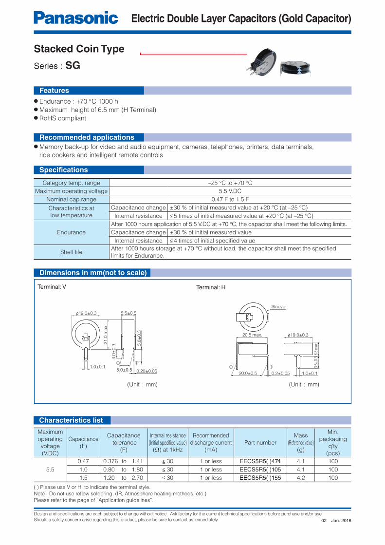
Electric Double Layer Capacitors (Gold Capacitor)
+–
f19.0±0.3
21.0
max.
1.0±0.1
5.0
±0.3
0.20±0.055.0±0.5
5.5±0.5
4.0
±0.3
20.5 max.
20.0±0.5
f19.0±0.3
1.0±0.10.2±0.05
6.5
max
.3.
5±0.
3Sleeve
● Endurance : +70 °C 1000 h● Category temperature range : –40 °C to +70 °C● Maximum height of 6.5 mm (H Terminal)● RoHS compliant
● Memory back-up for video and audio equipment, cameras, telephones, printers, data terminals,
rice cookers and intelligent remote controls
Stacked Coin Type
Series : SG Low temperature assured product
Features
Recommended applications
Specifi cations
Characteristics list
(Unit : mm) (Unit : mm)
Dimensions in mm(not to scale)
Category temp. range –40 °C to +70 °C
Maximum operating voltage 5.5 V.DC
Nominal cap.range 0.47 F to 1.5 F
Characteristics at
low temperature
Capacitance change ±30 % of initial measured value at +20 °C (at –40 °C)
Internal resistance < 7 times of initial measured value at +20 °C (at –40 °C)
Endurance
After 1000 hours application of 5.5 V.DC at +70 °C, the capacitor shall meet the following limits.
Capacitance change ±30 % of initial measured value
Internal resistance < 4 times of initial specifi ed value
Shelf lifeAfter 1000 hours storage at +70 °C without load, the capacitor shall meet the specifi ed
limits for Endurance.
( ) Please use V or H, to indicate the terminal style.
Note : Do not use refl ow soldering. (IR, Atmosphere heating methods, etc.)
Please refer to the page of “Application guidelines”.
Terminal: V Terminal: H
Maximum
op er at ing
volt age
(V.DC)
Capacitance
(F)
Capacitance
tolerance
(F)
Internal resistance
(Initial specifi ed value)(Ω) at 1kHz
Recommended
discharge current
(mA)
Part number
Mass
(Reference value)
(g)
Min.
packaging
q’ty
(pcs)
5.5
0.47 0.376 to 1.41 < 30 1 or less EECS5R5( )474N 4.1 100
1.0 0.80 to 1.80 < 30 1 or less EECS5R5( )105N 4.1 100
1.5 1.20 to 2.70 < 30 1 or less EECS5R5( )155N 4.2 100
Jan. 201601
Design and specifications are each subject to change without notice. Ask factory for the current technical specifications before purchase and/or use.
Should a safety concern arise regarding this product, please be sure to contact us immediately.
Electric Double Layer Capacitors (Gold Capacitor)
+–
f19.0±0.3
21.0
max.
1.0±0.1
5.0
±0.3
0.20±0.055.0±0.5
5.5±0.5
4.0
±0.3
20.5 max.
20.0±0.5
f19.0±0.3
1.0±0.10.2±0.05
6.5
max
.3.
5±0.
3
Sleeve
● Endurance : +70 °C 1000 h● Maximum height of 6.5 mm (H Terminal)● RoHS compliant
● Memory back-up for video and audio equipment, cameras, telephones, printers, data terminals,
rice cookers and intelligent remote controls
Stacked Coin Type
Series : SG
Features
Recommended applications
Specifi cations
Dimensions in mm(not to scale)
Characteristics list
(Unit : mm) (Unit : mm)
Category temp. range –25 °C to +70 °C
Maximum operating voltage 5.5 V.DC
Nominal cap.range 0.47 F to 1.5 F
Characteristics at
low temperature
Capacitance change ±30 % of initial measured value at +20 °C (at –25 °C)
Internal resistance < 5 times of initial measured value at +20 °C (at –25 °C)
Endurance
After 1000 hours application of 5.5 V.DC at +70 °C, the capacitor shall meet the following limits.
Capacitance change ±30 % of initial measured value
Internal resistance < 4 times of initial specifi ed value
Shelf lifeAfter 1000 hours storage at +70 °C without load, the capacitor shall meet the specifi ed
limits for Endurance.
Maximum
op er at ing
volt age
(V.DC)
Capacitance
(F)
Capacitance
tolerance
(F)
Internal resistance
(Initial specifi ed value)(Ω) at 1kHz
Recommended
discharge current
(mA)
Part number
Mass
(Reference value)
(g)
Min.
packaging
q’ty
(pcs)
5.5
0.47 0.376 to 1.41 < 30 1 or less EECS5R5( )474 4.1 100
1.0 0.80 to 1.80 < 30 1 or less EECS5R5( )105 4.1 100
1.5 1.20 to 2.70 < 30 1 or less EECS5R5( )155 4.2 100
( ) Please use V or H, to indicate the terminal style.
Note : Do not use refl ow soldering. (IR, Atmosphere heating methods, etc.)
Please refer to the page of “Application guidelines”.
Terminal: V Terminal: H
Jan. 201602

Design and specifications are each subject to change without notice. Ask factory for the current technical specifications before purchase and/or use.
Should a safety concern arise regarding this product, please be sure to contact us immediately.
Electric Double Layer Capacitors (Gold Capacitor)
P0 fD0
P1 F
P2 P
5.4±0.8
fd
H1
13.4
max.
H0
WW
1
W2
W0
△h
– + – +
△h1
10.5
max.
● Endurance : +70 °C 1000 h● Category temperature range : –40 °C to +70 °C● Automatic insertion available● RoHS compliant
● Memory back-up for video and audio equipment, cameras, telephones, printers, data terminals,
rice cookers and intelligent remote controls.
Stacked Coin Type
Series : SE Low temperature assured product
+0.8–0.2
Dimensions Nominal Tolerance
0d 0.55 ±0.05
P0 12.7 ±0.2
F 5.0
W 18.0 ±0.5
W0 5.5 < –
W1 9.0 ±0.5
W2 0 to 3.0 –
H0 16.4 ±0.5
0D0 4.0 ±0.2
P 12.7 ±1.0
P1 3.85 ±0.50
P2 6.35 ±1.00
△h, △h1 0 ±1.0
H1 30.3 > –
Category temp. range –40 °C to +70 °C
Maximum operating voltage 5.5 V.DC
Nominal cap.range 0.22 F
Characteristics at
low temperature
Capacitance change ±30 % of initial measured value at +20 °C (at –40 °C)
Internal resistance < 7 times of initial measured value at +20 °C (at –40 °C)
Endurance
After 1000 hours application of 5.5 V.DC at +70 °C, the capacitor shall meet the following limits.
Capacitance change ±30 % of initial measured value
Internal resistance < 4 times of initial specifi ed value
Shelf lifeAfter 1000 hours storage at +70 °C without load, the capacitor shall meet the specifi ed
limits for Endurance.
Note: 1. When ordering please observe the minimum packaging quantity.
2. When the surface mount component goes through UV or a heat oven to affi x the adhesive glue, the capacitor’s surface
temperature should not exceed 100 °C for more than 60 seconds (maximum tem per a ture should not exceed 105 °C)
3. Do not use refl ow soldering. (IR, Atmosphere heating methods, etc.)
Please refer to the page of “Application guidelines”.
Maximum
op er at ing
volt age
(V.DC)
Capacitance
(F)
Capacitance
tolerance
(F)
Internal resistance
(Initial specifi ed value)(Ω) at 1kHz
Recommended
discharge current
(µA)
Part number
Mass
(Reference value)
(g)
Min.
packaging
q’ty
(pcs)
5.5 0.22 0.176 to 0.396 < 75 300 or less EECSE0H224N 1.0 1000
Characteristics list
(Unit : mm)
Features
Recommended applications
Specifi cations
Dimensions in mm(not to scale)
Jan. 201601

Design and specifications are each subject to change without notice. Ask factory for the current technical specifications before purchase and/or use.
Should a safety concern arise regarding this product, please be sure to contact us immediately.
Electric Double Layer Capacitors (Gold Capacitor)
P0 fD0
P1 F
P2 P
5.4±0.8
fd
H1
13.4
max.
H0
WW
1
W2
W0
△h
– + – +
△h1
10.5
max.
Stacked Coin Type
Series : SE
Dimensions in mm(not to scale)
Characteristics list
(Unit : mm)
● Endurance : +70 °C 1000 h● Automatic insertion available● RoHS compliant
● Memory back-up for video and audio equipment,cameras, telephones, printers, data terminals,
rice cookers and intelligent remote controls.
+0.8–0.2
Dimensions Nominal Tolerance
0d 0.55 ±0.05
P0 12.7 ±0.2
F 5.0
W 18.0 ±0.5
W0 5.5 < –
W1 9.0 ±0.5
W2 0 to 3.0 –
H0 16.4 ±0.5
0D0 4.0 ±0.2
P 12.7 ±1.0
P1 3.85 ±0.50
P2 6.35 ±1.00
△h, △h1 0 ±1.0
H1 30.3 > –
Features
Recommended applications
Specifi cations
Category temp. range –25 °C to +70 °C
Maximum operating voltage 5.5 V.DC
Nominal cap.range 0.22 F
Characteristics at
low temperature
Capacitance change ±30 % of initial measured value at +20 °C (at –25 °C)
Internal resistance < 5 times of initial measured value at +20 °C (at –25 °C)
Endurance
After 1000 hours application of 5.5 V.DC at +70 °C, the capacitor shall meet the following limits.
Capacitance change ±30 % of initial measured value
Internal resistance < 4 times of initial specifi ed value
Shelf lifeAfter 1000 hours storage at +70 °C without load, the capacitor shall meet the specifi ed
limits for Endurance.
Note: 1. When ordering please observe the minimum packaging quantity.
2. When the surface mount component goes through UV or a heat oven to affi x the adhesive glue, the capacitor’s surface
temperature should not exceed 100 °C for more than 60 seconds (maximum tem per a ture should not exceed 105 °C)
3. Do not use refl ow soldering. (IR, Atmosphere heating methods, etc.)
Please refer to the page of “Application guidelines”.
Maximum
op er at ing
volt age
(V.DC)
Capacitance
(F)
Capacitance
tolerance
(F)
Internal resistance
(Initial specifi ed value)(Ω) at 1kHz
Recommended
discharge current
(µA)
Part number
Mass
(Reference value)
(g)
Min.
packaging
q’ty
(pcs)
5.5 0.22 0.176 to 0.396 < 75 300 or less EECSE0H224 1.0 1000
Jan. 201605

Design and specifications are each subject to change without notice. Ask factory for the current technical specifications before purchase and/or use.
Should a safety concern arise regarding this product, please be sure to contact us immediately.
Electric Double Layer Capacitors (Gold Capacitor)
Sleeve
L max. 6±1
5.0
±0.3
0.5
±0.1
0D m
ax.
2.5
±0.5
3.5
±0.5 6
±1
1.2±0.1
0.8±0.1
+–
+
–
5.0
01.1±0.05
(Recommended)
● Endurance : +70 °C 1000 h● Category temperature range : –40 °C to +70 °C● RoHS compliant
● Memory back-up for video and audio equipment, cameras, telephones, printers, data terminals,
rice cookers and intelligent remote controls.
Stacked Coin Type
Series : NF Low temperature assured product
Characteristics list
Features
Recommended applications
Specifi cations
Dimensions in mm(not to scale)
Category temp. range –40 °C to +70 °C
Maximum operating voltage 5.5 V.DC
Nominal cap.range 0.22 F to 1.5 F
Characteristics at
low temperature
Capacitance change ±30 % of initial measured value at +20 °C (at –40 °C)
Internal resistance < 7 times of initial measured value at +20 °C (at –40 °C)
Endurance
After 1000 hours application of 5.5 V.DC at +70 °C, the capacitor shall meet the following limits.
Capacitance change ±30 % of initial measured value
Internal resistance < 4 times of initial specifi ed value
Shelf lifeAfter 1000 hours storage at +70 °C without load, the capacitor shall meet the specifi ed
limits for Endurance.
Note : Do not use refl ow soldering. (IR, Atmosphere heating methods, etc.)
Please refer to the page of “Application guidelines”.
Case
code
Size
D L
A 13.5 7.5
B 21.5 8.0
Maximum
op er at ing
volt age
(V.DC)
Capacitance
(F)
Capacitance
tolerance
(F)
Internal resistance
(Initial specifi ed value)(Ω) at 1 kHz
Recommended
discharge currentParts number
Case
code
Mass
(Reference value)
(g)
Min.
packaging
q’ty
(pcs)
5.5
0.22 0.176 to 0.396 < 75 300 µA or less EECF5R5U224N A 2.6 200
0.47 0.376 to 1.41 < 30 1 mA or less EECF5R5U474N B 7.9 100
1.0 0.80 to 1.80 < 30 1 mA or less EECF5R5U105N B 8.1 100
1.5 1.20 to 2.70 < 30 1 mA or less EECF5R5U155N B 8.1 100
(Unit : mm)
Jan. 201601

Design and specifications are each subject to change without notice. Ask factory for the current technical specifications before purchase and/or use.
Should a safety concern arise regarding this product, please be sure to contact us immediately.
Electric Double Layer Capacitors (Gold Capacitor)
Sleeve
L max. 6±1
5.0
±0.3
0.5
±0.1
0D m
ax.
2.5
±0.5
3.5
±0.5 6
±1
1.2±0.1
0.8±0.1
+–
+
–
5.0
01.1±0.05
(Recommended)
Stacked Coin Type
Series : NF
Dimensions in mm(not to scale)
● Endurance : +70 °C 1000 h● RoHS compliant
● Memory back-up for video and audio equipment, cameras, telephones, printers, data terminals,
rice cookers and intelligent remote controls.
Features
Recommended applications
Specifi cations
Category temp. range –25 °C to +70 °C
Maximum operating voltage 5.5 V.DC
Nominal cap.range 0.22 F to 1.5 F
Characteristics at
low temperature
Capacitance change ±30 % of initial measured value at +20 °C (at –25 °C)
Internal resistance < 5 times of initial measured value at +20 °C (at –25 °C)
Endurance
After 1000 hours application of 5.5 V.DC at +70 °C, the capacitor shall meet the following limits.
Capacitance change ±30 % of initial measured value
Internal resistance < 4 times of initial specifi ed value
Shelf lifeAfter 1000 hours storage at +70 °C without load, the capacitor shall meet the specifi ed
limits for Endurance.
Note : Do not use refl ow soldering. (IR, Atmosphere heating methods, etc.)
Please refer to the page of “Application guidelines”.
Case
code
Size
D L
A 13.5 7.5
B 21.5 8.0
(Unit : mm)
Maximum
op er at ing
volt age
(V.DC)
Capacitance
(F)
Capacitance
tolerance
(F)
Internal resistance
(Initial specifi ed value)(Ω) at 1 kHz
Recommended
discharge currentParts number
Case
code
Mass
(Reference value)
(g)
Min.
packaging
q’ty
(pcs)
5.5
0.22 0.176 to 0.396 < 75 300 µA or less EECF5R5U224 A 2.6 200
0.47 0.376 to 1.41 < 30 1 mA or less EECF5R5U474 B 7.9 100
1.0 0.80 to 1.80 < 30 1 mA or less EECF5R5U105 B 8.1 100
1.5 1.20 to 2.70 < 30 1 mA or less EECF5R5U155 B 8.1 100
Characteristics list
Jan. 201604

Design and specifications are each subject to change without notice. Ask factory for the current technical specifications before purchase and/or use.
Should a safety concern arise regarding this product, please be sure to contact us immediately.
Electric Double Layer Capacitors (Gold Capacitor)
Sleeve
L max. 6±1
5.0
±0.3
0.5
±0.1
0 D m
ax.
2.5
±0.5
3.5
±0.5 6
±1
1.2±0.1
0.8±0.1
+–
+
–
5.0
01.1±0.05
(Recommended)
● Endurance : +85 °C 1000 h● Category temperature range : –40 °C to +85 °C● RoHS compliant
● Backup of data/RTC of base station,electronic meter, and industrial equipment
Stacked Coin Type
Series : F Low temperature assured product
Characteristics list
Features
Recommended Applications
Specifi cations
Dimensions in mm(not to scale)
(Unit : mm)
Category temp. range –40 °C to +85 °C
Maximum operating voltage 5.5 V.DC
Nominal cap.range 0.1 F to 1.0 F
Characteristics at
low temperature
Capacitance change ±30 % of initial measured value at +20 °C (at –40 °C)
Internal resistance < 7 times of initial measured value at +20 °C (at –40 °C)
Endurance
After 1000 hours application of 5.5 V.DC at +85 °C, the capacitor shall meet the following limits.
Capacitance change ±30 % of initial measured value
Internal resistance < 4 times of initial specifi ed value
Shelf LifeAfter 1000 hours storage at +85 °C without load, the capacitor shall meet the specifi ed
limits for Endurance.
Note : Do not use refl ow soldering. (IR, Atmosphere heating methods, etc.)
Please refer to the page of “Application guidelines”.
Case
code
Size
D L
A 13.5 9.5
B 21.5 9.5
Maximum
op er at ing
volt age
(V.DC)
Capacitance
(F)
Capacitance
tolerance
(F)
Internal resistance
(Initial specifi ed value)(Ω)at 1 kHz
Recommended
discharge currentParts number
Case
code
Mass
(Reference value)
(g)
Min.
packaging
q’ty
(pcs)
5.5
0.10 0.080 to 0.180 < 100 300 µA or less EECF5R5H104N A 3.3 200
0.47 0.376 to 0.846 < 75 1 mA or less EECF5R5H474N B 10.0 100
0.68 0.544 to 1.224 < 50 1 mA or less EECF5R5H684N B 10.0 100
1.00 0.80 to 1.80 < 50 1 mA or less EECF5R5H105N B 10.0 100
Jan. 201601

Design and specifications are each subject to change without notice. Ask factory for the current technical specifications before purchase and/or use.
Should a safety concern arise regarding this product, please be sure to contact us immediately.
Electric Double Layer Capacitors (Gold Capacitor)
Sleeve
L max. 6±1
5.0
±0.3
0.5
±0.1
0 D m
ax.
2.5
±0.5
3.5
±0.5 6
±1
1.2±0.1
0.8±0.1
+–
+
–
5.0
01.1±0.05
(Recommended)
Stacked Coin Type
Series : F
● Endurance : +85 °C 1000 h● RoHS compliant
● Backup of data/RTC of base station, electronic meter, and industrial equipmet
Features
Recommended Applications
Specifi cations
(Unit : mm)
Characteristics list
Category temp. range –25 °C to +85 °C
Maximum operating voltage 5.5 V.DC
Nominal cap.range 0.1 F to 1.0 F
Characteristics at
low temperature
Capacitance change ±30 % of initial measured value at +20 °C (at –25 °C)
Internal resistance < 5 times of initial measured value at +20 °C (at –25 °C)
Endurance
After 1000 hours application of 5.5 V.DC at +85 °C, the capacitor shall meet the following limits.
Capacitance change ±30 % of initial measured value
Internal resistance < 4 times of initial specifi ed value
Shelf LifeAfter 1000 hours storage at +85 °C without load, the capacitor shall meet the specifi ed
limits for Endurance.
Note : Do not use refl ow soldering. (IR, Atmosphere heating methods, etc.)
Please refer to the page of “Application guidelines”.
Case
code
Size
D L
A 13.5 9.5
B 21.5 9.5
Maximum
op er at ing
volt age
(V.DC)
Capacitance
(F)
Capacitance
tolerance
(F)
Internal resistance
(Initial specifi ed value)(Ω) at 1 kHz
Recommended
discharge currentParts number
Case
code
Mass
(Reference value)
(g)
Min.
packaging
q’ty
(pcs)
5.5
0.10 0.080 to 0.180 < 100 300 µA or less EECF5R5H104 A 3.3 200
0.47 0.376 to 0.846 < 75 1 mA or less EECF5R5H474 B 10.0 100
0.68 0.544 to 1.224 < 50 1 mA or less EECF5R5H684 B 10.0 100
1.00 0.80 to 1.80 < 50 1 mA or less EECF5R5H105 B 10.0 100
Dimensions in mm(not to scale)
Jan. 201603

Design and specifications are each subject to change without notice. Ask factory for the current technical specifications before purchase and/or use.
Should a safety concern arise regarding this product, please be sure to contact us immediately.
Electric Double Layer Capacitors (Gold Capacitor)
(>8.0 mm dia.)
L+2 max.
Sleeve
14 min. 3 min. 0D+0.5 max.
0d±0.05
P±
0.5
Vent
Radial Lead Type
Series : HZ
● Miniaturized, High voltage● Can be discharge mA or more current● RoHS compliant
● Solar battery operated circuits● Back-up Power Supplies (UPS)
Features
Recommended Applications
Specifi cations
(Unit : mm)
Characteristics list
Dimensions in mm(not to scale)
Category temp. range –25 °C to +70 °C
Maximum operating voltage 2.5 V.DC
Nominal cap. range 3.3 F 4.7 F 10 F
Characteristics at
low temperature
Capacitance change ±30 % of initial measured value at 20 °C (at –25 °C)
Internal resistance < 4 times of initial specifi ed value. (at –25 °C)
Endurance
After 1000 hours application of 2.5 V.DC at +70 °C
Capacitance change ±30 % of initial measured value at 20 °C
Internal resistance < 4 times of initial specifi ed value.
Shelf Life
After 1000 hours storage at +70 °C without load (voltage)
Capacitance change ±30 % of initial measured value at 20 °C
Internal resistance < 4 times of initial specifi ed value.
✽1 The recommended discharge current is a reference value. Please design your equipment (circuit) in consideration of IR drop.
Do not use refl ow soldering. Please refer to the page of “Application guidelines”.Remark1: Install the space of 2 mm or more in the upper part of the product so as not to disturb the movement of the pressure valve.
Capacitance(F)
0D L 0d P
3.3 8.0 20 0.6 3.5
4.7 10 20 0.6 5.0
10 10 30 0.6 5.0
Category
temp.
range
(°C)
Maximum
operating
voltage
(V.DC)
Capacitance
(F)
Capacitance
tolerance
(F)
Internal
resistance
(Initial specifi ed value)(Ω) at 1 kHz
Recommended ✽1
discharge currentParts number
Mass
(Reference value)
(g)
Min.
packaging
q’ty
(pcs)
–25 to +70 2.5
3.3 2.64 to 4.62 < 0.3 300 mA or less EECHZ0E335 1.5 200
4.7 3.76 to 6.58 < 0.3 300 mA or less EECHZ0E475 2.1 200
10 8 to 14 < 0.2 1 A or less EECHZ0E106 3.1 200
Aug. 201603

Design and specifications are each subject to change without notice. Ask factory for the current technical specifications before purchase and/or use.
Should a safety concern arise regarding this product, please be sure to contact us immediately.
Electric Double Layer Capacitors (Gold Capacitor)
(>8.0 mm dia.)
L+2 max.
Sleeve
14 min. 3 min. 0D+0.5 max.
0d±0.05
P±
0.5
Vent
Radial lead Type
Series : HW
● Guaranteed at 70 °C (60°C 1000 h)● Can be discharge mA or more current● RoHS compliant
● Solar battery operated circuits (Road guidance fl asher), Quick charging motor drives (Toy car)● Back-up Power Supplies (UPS)
Features
Recommended Applications
Specifi cations
(Unit : mm)
Characteristics list
Dimensions in mm(not to scale)
Note : 1. Do not use refl ow soldering. (IR, Atmosphere heating methods, etc. )
Please refer to the page of “Application guidelines”.
✽ : 10 F or less HW series is not recommended for new design. Please consider HZ series.
Capacitance(F)
0D L 0d P
22 18.0 35.0 0.8 7.5
30 18.0 35.0 0.8 7.5
50 18.0 40.0 0.8 7.5
70 18.0 50.0 0.8 7.5
Category
temp.
range
(°C)
Maximum
operating
voltage
(V.DC)
Capacitance
(F)
Capacitance
tolerance
(F)
Internal
resistance
(Initial specifi ed value)(Ω) at 1 kHz
Recommended
discharge
current
(A)
Parts number
Mass
(Reference value)
(g)
Min.
packaging
q’ty
(pcs)
–25 to +70
2.3
22 17.6 to 30.8 < 0.1 1 or less EECHW0D226 12.0 50
–25 to +60
30 24.0 to 42.0 < 0.1 1 or less EECHW0D306 14.0 50
50 40.0 to 70.0 < 0.1 1 or less EECHW0D506 15.0 50
2.1 70 56.0 to 98.0 < 0.1 1 or less EECHW0D706 19.0 50
Category temp. range –25 °C to +70 °C –25 °C to +60 °C
Maximum operating voltage 2.3 V.DC 2.3 V.DC 2.1 V.DC
Nominal cap. range 22 F 30, 50 F 70 F
Characteristics at
low Temperature
Capacitance change ±30 % of initial measured value at +20 °C (at –25 °C)
Internal resistance < 4 times of initial measured value at +20 °C (at –25 °C)
Endurance
After 1000 hours application of 2.3 V.DC at +70 °C (+60 °C), the capacitor shall meet the
following limits.
Capacitance change ±30 % of initial measured value
Internal resistance < 2 time of initial specifi ed value
Shelf LifeAfter 1000 hours storage at +70 °C (+60 °C) without load, the capacitor shall meet the
specifi ed limits for Endurance.
Jan. 201603


Design and specifications are each subject to change without notice. Ask factory for the current technical specifications before purchase and/or use.
Should a safety concern arise regarding this product, please be sure to contact us immediately.
Electric Double Layer Capacitors (Gold Capacitor)
L+2 max.
Sleeve
14 min. 3 min. fD+0.5 max.
fd±0.05
P ±
0.5Vent
● Guaranteed 70 °C 2.7 V.DC 2000 h
Guaranteed 85 °C 2.5 V.DC 1000 h
● Low resistance : 30 mΩ max. (1 kHz) ✽1
● Low temperature : –40 °C guaranteed● RoHS compliant
● Backup power supply of E-meter, storage (SSD)● Driver assist of motor, actuator● Backup for power supply of drive recorder, emergency brake, door lock releasing device
Recommended Applications
Features
Radial Lead TypeSeries : HL Small size
Unit : mm
Category temp. range
(°C)
Maximum operating voltage
(V.DC)
Capacitance(F)
Capacitance tolerance
(F)
Internal resistance(Initial specifi ed value)(Ω) at 1 kHz
Recommended ✽2
discharge currentParts number
Mass(Reference value)
(g)
Min. Packaging Q'ty
(pcs)
–40 to +70(+85)
2.7(2.5)
2.5 2.0 to 3.0 < 0.07 < 2.5 A EECHL0E255 1.5 200
4.0 3.2 to 4.8 < 0.05 < 3.5 A EECHL0E405 2.3 200
7.5 6.0 to 9.0 < 0.03 < 6.0 A EECHL0E755 3.4 200
✽1 010×L30✽2 The recommended discharge current is a reference value. Please design your equipment (circuit) in consideration of IR drop.
Do not use refl ow soldering. Please refer to the page of “Application guidelines”.Remark1: Install the space of 2 mm or more in the upper part of the product so as not to disturb the movement of the pressure valve.
Category temp. range –40 °C to +70 °C (+85 °C)
Maximum operating voltage 2.7 V.DC (2.5 V.DC)
Nominal cap. range 2.5 F 4.0 F 7.5 F
Characteristics at low temprature
Capacitance change ±30 % of initial measured value at +20 °C (at –40 °C)
Internal resistance < 4 times of initial specifi ed value. (at –40 °C)
Endurance 1
After 2000 hours application of 2.7 V.DC at +70 °C
Capacitance change Within ±40 % of the initial value
Internal resistance < 4 times of initial specifi ed value.
Endurance 2
After 1000 hours application of 2.5 V.DC at +85 °C
Capacitance change Within ±40 % of the initial value
Internal resistance < 4 times of initial specifi ed value.
Shelf life
After 1000 hours storage at +85 °C 1000 h without load (voltage)
Capacitance change Within ±40 % of the initial value
Internal resistance < 4 times of initial specifi ed value.
Capacitance(F)
0D L 0d P
2.5 8.0 20.0 0.6 3.5
4.0 10.0 20.0 0.6 5.0
7.5 10.0 30.0 0.6 5.0
Specifi cations
Dimensions (not to scale)
Characteristics list
NEW
Jan. 201700


Please contact Factory
CAUTION AND WARNING
The information in this catalog is valid as of March 2018.
1. The electronic components contained in this catalog are designed and produced for use in home electric appliances, office equipment, information equipment,communications equipment, and other general purpose electronic devices. Before use of any of these components for equipment that requires a high degree of safety, such as medical instruments, aerospace equipment, disaster-prevention equipment, security equipment, vehicles (automobile, train, vessel), please be sure to contact our sales representative corporation.
2. When applying one of these components for equipment requiring a high degree of safety, no matter what sort of application it might be, be sure to install a protective circuit or redundancy arrangement to enhance the safety of your equipment. In addition, please carry out the safety test on your own responsibility.
3. When using our products, no matter what sort of equipment they might be used for, be sure to make a written agreement on the specifications with us in advance.
4. Technical information contained in this catalog is intended to convey examples of typical performances and or applications and is not intended to make any warranty with respect to the intellectual property rights or any other related rights of our company or any third parties nor grant any license under such rights.
5. In order to export products in this catalog, the exporter may be subject to the export license requirement under the Foreign Exchange and Foreign Trade Law of Japan.
6. No ozone-depleting substances (ODSs) under the Montreal Protocol are used in the manufacturing processes of Automotive & Industrial Systems Company, Panasonic Corporation.