Embed Size (px)
Citation preview
Electric Machine Simulation TechnologySteve Hartridge
Director, Electric & Hybrid Vehicles
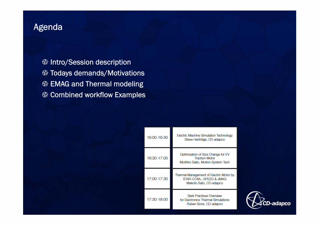
Intro/Session descriptionTodays demands/MotivationsEMAG and Thermal modelingCombined workflow Examples
Agenda
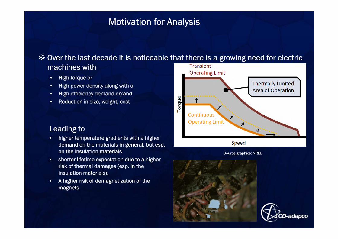
Over the last decade it is noticeable that there is a growing need for electric machines with • High torque or • High power density along with a • High efficiency demand or/and• Reduction in size, weight, cost
Leading to• higher temperature gradients with a higher
demand on the materials in general, but esp. on the insulation materials
• shorter lifetime expectation due to a higher risk of thermal damages (esp. in the insulation materials).
• A higher risk of demagnetization of the magnets
Source graphics: NREL
Motivation for Analysis
Motivation for Analysis
Component lifetime estimates [1]:– 22% of failures due to thermal damages in insulation– 17% further thermal damage in other components
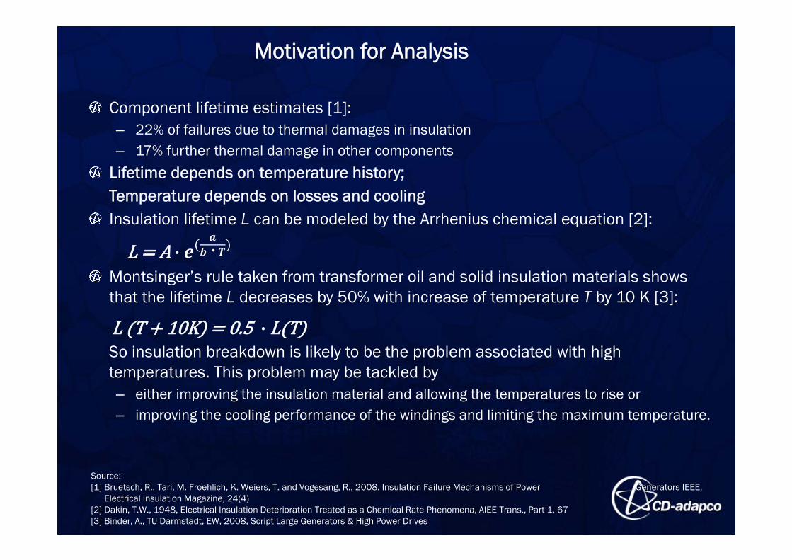
Lifetime depends on temperature history; Temperature depends on losses and coolingInsulation lifetime L can be modeled by the Arrhenius chemical equation [2]:
Montsinger’s rule taken from transformer oil and solid insulation materials shows that the lifetime L decreases by 50% with increase of temperature T by 10 K [3]:
So insulation breakdown is likely to be the problem associated with high temperatures. This problem may be tackled by – either improving the insulation material and allowing the temperatures to rise or – improving the cooling performance of the windings and limiting the maximum temperature.
L A· ⋅
L T 10K 0.5·L T
Source:[1] Bruetsch, R., Tari, M. Froehlich, K. Weiers, T. and Vogesang, R., 2008. Insulation Failure Mechanisms of Power Generators IEEE,
Electrical Insulation Magazine, 24(4)[2] Dakin, T.W., 1948, Electrical Insulation Deterioration Treated as a Chemical Rate Phenomena, AIEE Trans., Part 1, 67[3] Binder, A., TU Darmstadt, EW, 2008, Script Large Generators & High Power Drives
To accomplish today’s demand the new machine designs have– to eliminate the safety factors of the over-sizing designs of the past– to finally ensure the requested high power densities.
The need to have an optimized thermal design besides an optimized electro-magnetic design.
Motivation for Analysis
Electric Machine Simulation Technology
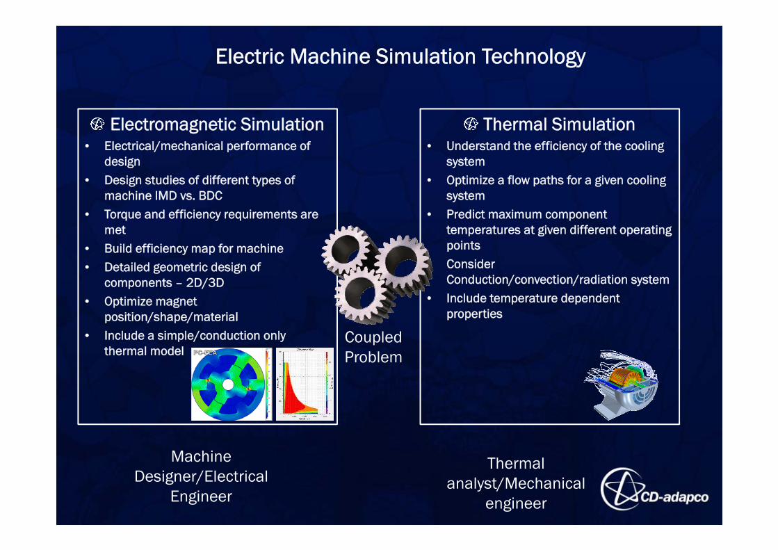
Electromagnetic Simulation• Electrical/mechanical performance of
design• Design studies of different types of
machine IMD vs. BDC• Torque and efficiency requirements are
met• Build efficiency map for machine• Detailed geometric design of
components – 2D/3D• Optimize magnet
position/shape/material• Include a simple/conduction only
thermal model
Thermal Simulation• Understand the efficiency of the cooling
system• Optimize a flow paths for a given cooling
system• Predict maximum component
temperatures at given different operating points
• Consider Conduction/convection/radiation system
• Include temperature dependent properties
CoupledProblem
MachineDesigner/Electrical
Engineer
Thermal analyst/Mechanical
engineer
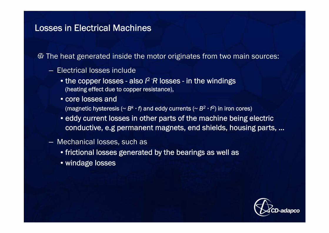
The heat generated inside the motor originates from two main sources:
– Electrical losses include • the copper losses - also I2 ·R losses - in the windings
(heating effect due to copper resistance),
• core losses and(magnetic hysteresis (~ Bk · f) and eddy currents (~ B2 · f2) in iron cores)
• eddy current losses in other parts of the machine being electric conductive, e.g permanent magnets, end shields, housing parts, …
– Mechanical losses, such as• frictional losses generated by the bearings as well as • windage losses
Losses in Electrical Machines
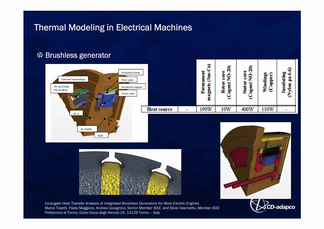
Conjugate Heat Transfer Analysis of Integrated Brushless Generators for More Electric Engines Marco Tosetti, Paolo Maggiore, Andrea Cavagnino, Senior Member IEEE, and Silvio Vaschetto, Member IEEEPolitecnico di Torino, Corso Duca degli Abruzzi 24, 10129 Torino – Italy
Brushless generator
Thermal Modeling in Electrical Machines
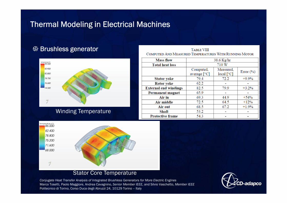
Winding Temperature
Stator Core Temperature
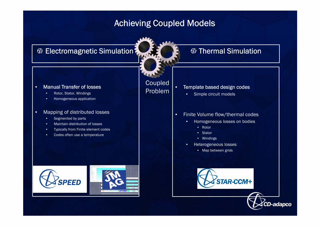
Achieving Coupled Models
Electromagnetic Simulation Thermal Simulation
CoupledProblem
• Manual Transfer of losses• Rotor, Stator, Windings• Homogeneous application
• Mapping of distributed losses• Segmented by parts• Maintain distribution of losses• Typically from Finite element codes• Codes often use a temperature
• Template based design codes• Simple circuit models
• Finite Volume flow/thermal codes• Homogeneous losses on bodies
• Rotor• Stator• Windings
• Heterogeneous losses• Map between grids
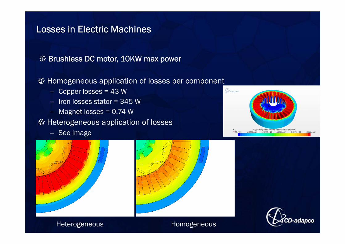
Losses in Electric Machines
Homogeneous application of losses per component– Copper losses = 43 W– Iron losses stator = 345 W– Magnet losses = 0.74 W
Heterogeneous application of losses– See image
Comparison of Solution
Heterogeneous Homogeneous
Brushless DC motor, 10KW max power
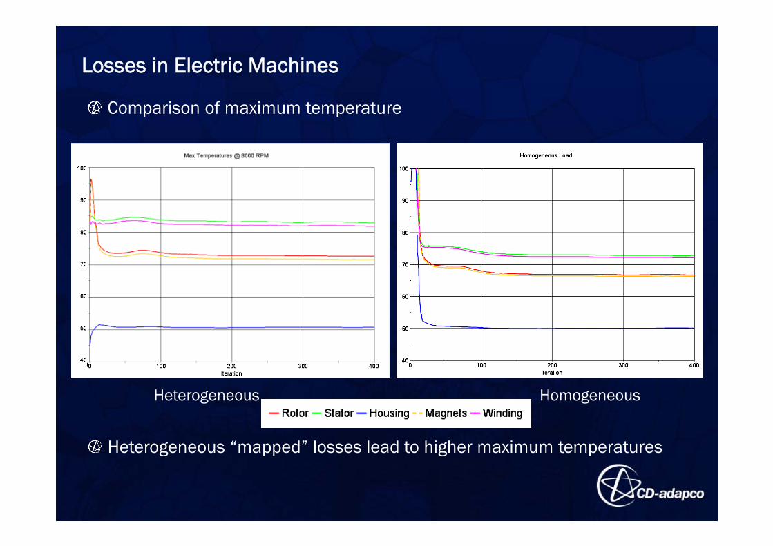
Losses in Electric Machines
Comparison of maximum temperature
Heterogeneous Homogeneous
Heterogeneous “mapped” losses lead to higher maximum temperatures
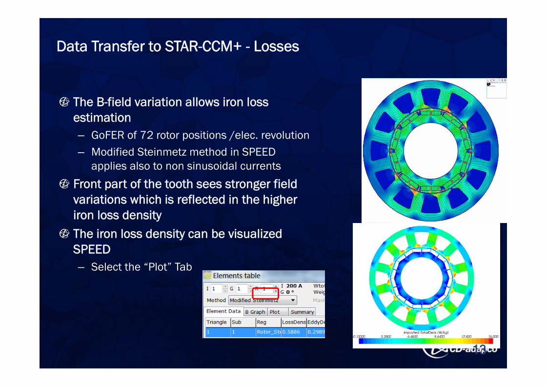
The B-field variation allows iron loss estimation– GoFER of 72 rotor positions /elec. revolution– Modified Steinmetz method in SPEED
applies also to non sinusoidal currents
Front part of the tooth sees stronger field variations which is reflected in the higher iron loss densityThe iron loss density can be visualized SPEED– Select the “Plot” Tab
Data Transfer to STAR-CCM+ - Losses
13
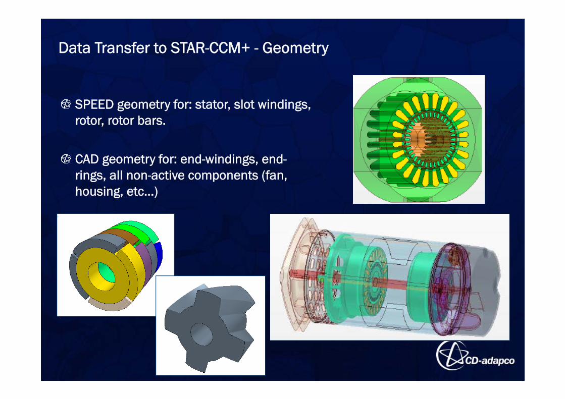
Data Transfer to STAR-CCM+ - Geometry
SPEED geometry for: stator, slot windings, rotor, rotor bars.
CAD geometry for: end-windings, end-rings, all non-active components (fan, housing, etc…)
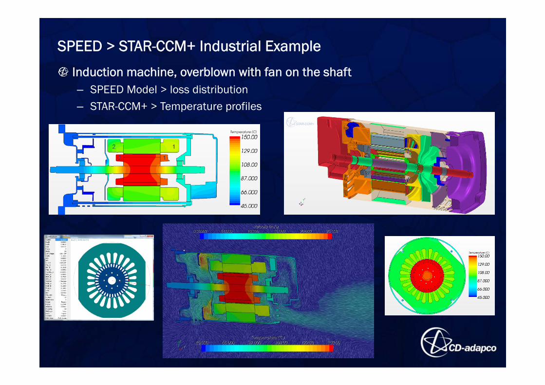
SPEED > STAR-CCM+ Industrial Example
Induction machine, overblown with fan on the shaft– SPEED Model > loss distribution – STAR-CCM+ > Temperature profiles
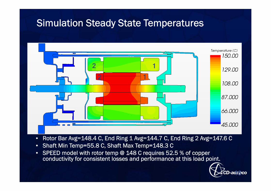
• Rotor Bar Avg=148.4 C, End Ring 1 Avg=144.7 C, End Ring 2 Avg=147.6 C• Shaft Min Temp=55.8 C, Shaft Max Temp=148.3 C• SPEED model with rotor temp @ 148 C requires 52.5 % of copper
conductivity for consistent losses and performance at this load point.
16
Simulation Steady State Temperatures
1
1
2
2
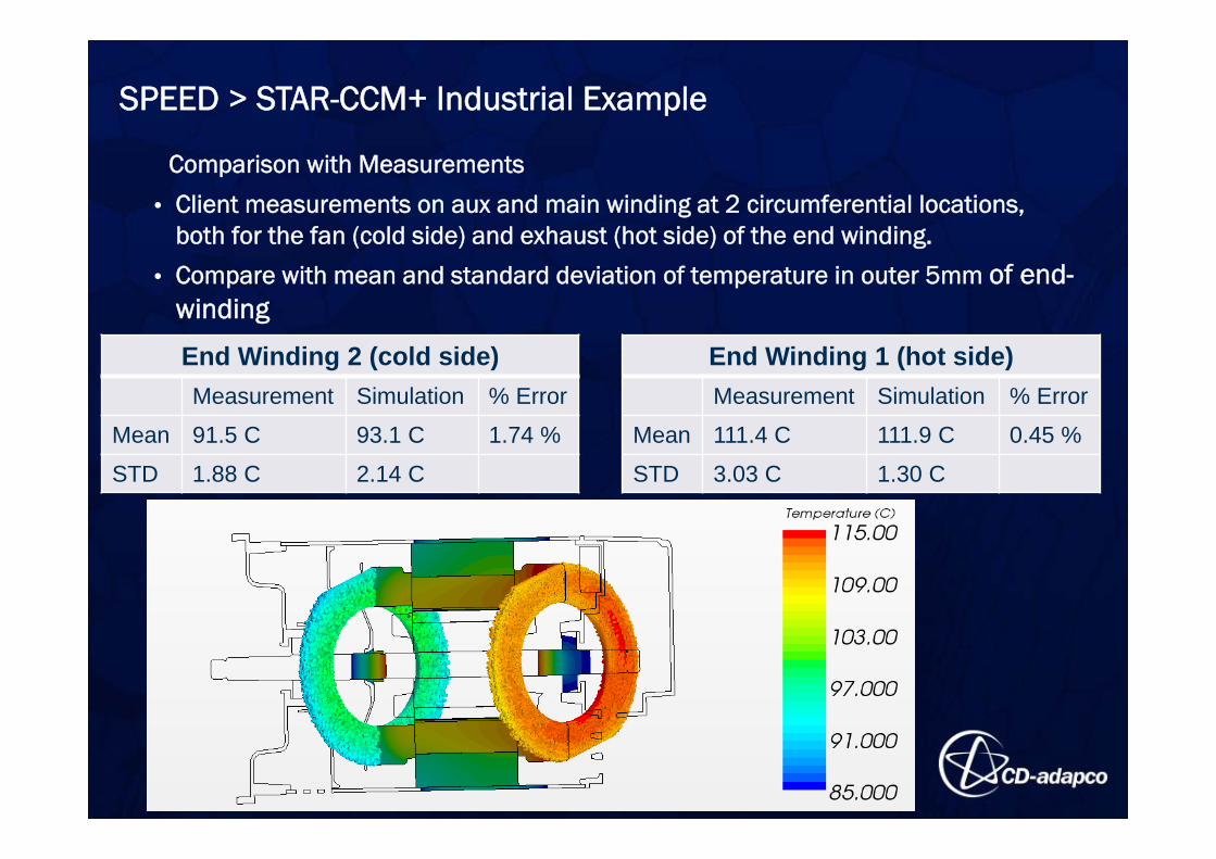
Comparison with Measurements
• Client measurements on aux and main winding at 2 circumferential locations, both for the fan (cold side) and exhaust (hot side) of the end winding.
• Compare with mean and standard deviation of temperature in outer 5mm of end-winding
End Winding 2 (cold side)Measurement Simulation % Error
Mean 91.5 C 93.1 C 1.74 %
STD 1.88 C 2.14 C
End Winding 1 (hot side)Measurement Simulation % Error
Mean 111.4 C 111.9 C 0.45 %
STD 3.03 C 1.30 C
SPEED > STAR-CCM+ Industrial Example
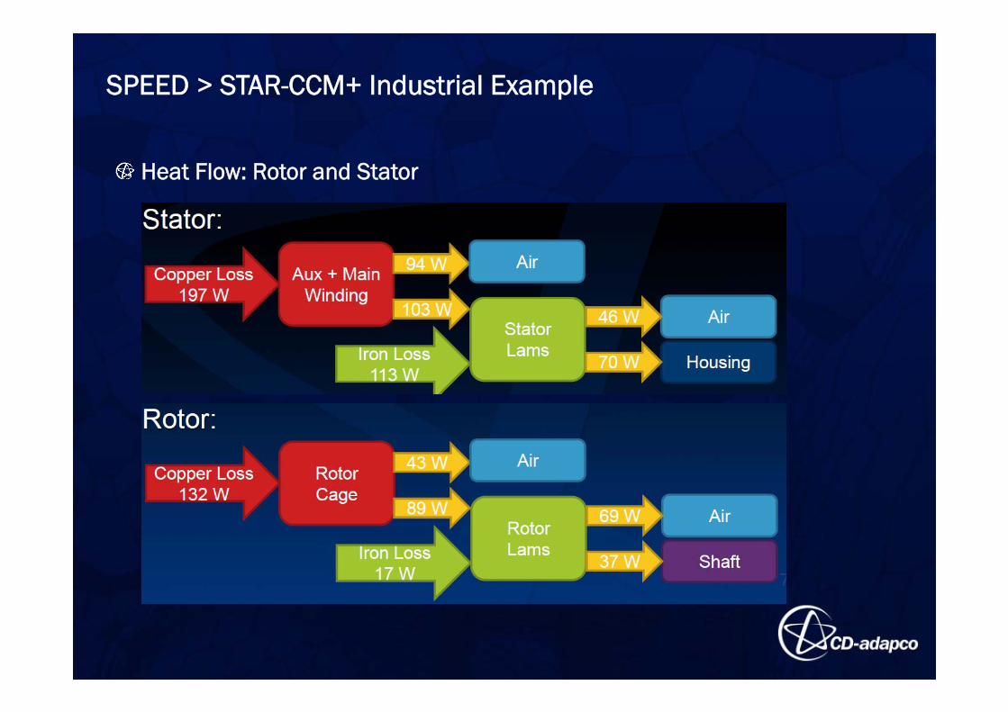
Heat Flow: Rotor and Stator
SPEED > STAR-CCM+ Industrial Example
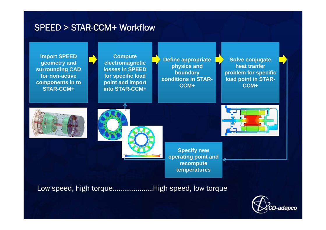
SPEED > STAR-CCM+ Workflow
Import SPEED geometry and
surrounding CAD for non-active
components in to STAR-CCM+
Compute electromagnetic losses in SPEED for specific load point and import into STAR-CCM+
Define appropriate physics and
boundary conditions in STAR-
CCM+
Solve conjugate heat tranfer
problem for specific load point in STAR-
CCM+
Specify new operating point and
recomputetemperatures
Low speed, high torque…………………High speed, low torque
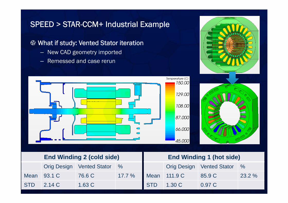
What if study: Vented Stator iteration– New CAD geometry imported– Remessed and case rerun
SPEED > STAR-CCM+ Industrial Example
End Winding 2 (cold side)Orig Design Vented Stator %
Mean 93.1 C 76.6 C 17.7 %
STD 2.14 C 1.63 C
End Winding 1 (hot side)Orig Design Vented Stator %
Mean 111.9 C 85.9 C 23.2 %
STD 1.30 C 0.97 C
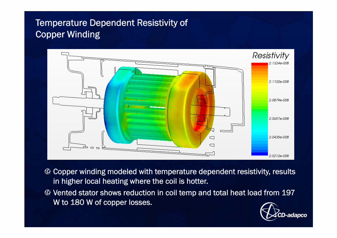
Copper winding modeled with temperature dependent resistivity, results in higher local heating where the coil is hotter.Vented stator shows reduction in coil temp and total heat load from 197 W to 180 W of copper losses.
Temperature Dependent Resistivity of Copper Winding
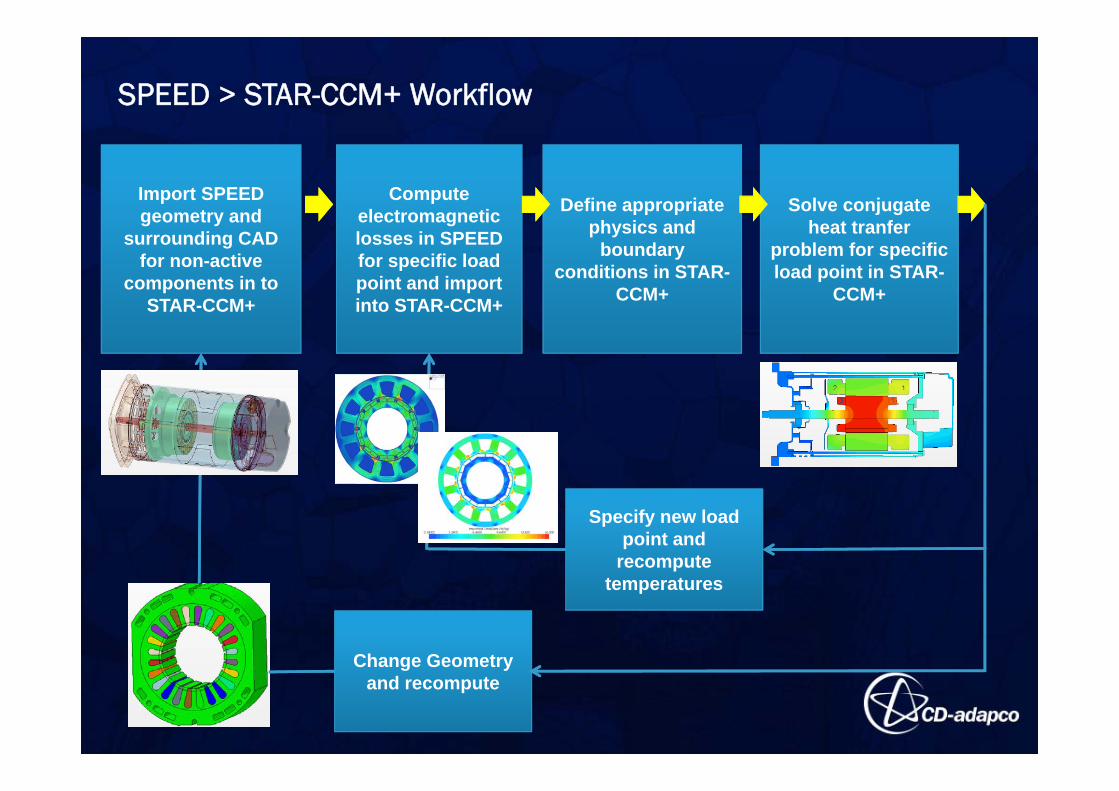
SPEED > STAR-CCM+ Workflow
Import SPEED geometry and
surrounding CAD for non-active
components in to STAR-CCM+
Compute electromagnetic losses in SPEED for specific load point and import into STAR-CCM+
Define appropriate physics and
boundary conditions in STAR-
CCM+
Solve conjugate heat tranfer
problem for specific load point in STAR-
CCM+
Specify new load point and
recomputetemperatures
Change Geometry and recompute
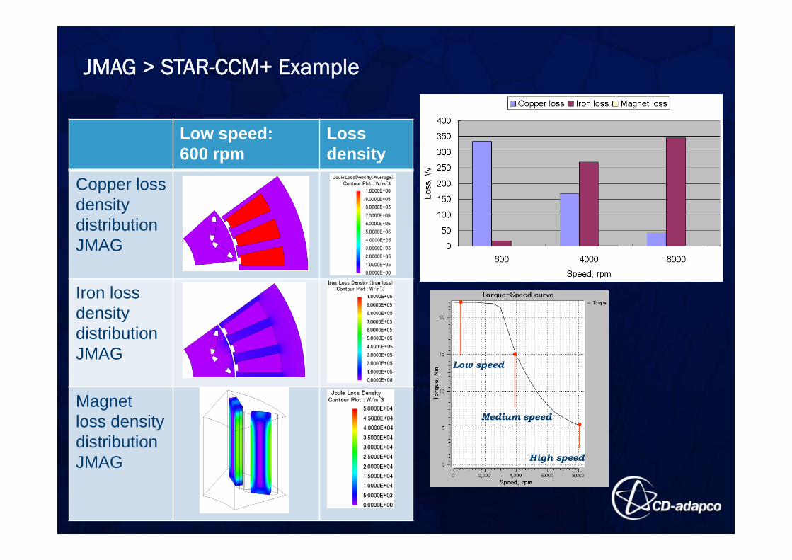
JMAG > STAR-CCM+ Example
Low speed:600 rpm
Loss density
Copper loss density distribution JMAG
Iron loss density distribution JMAG
Magnet loss density distribution JMAG
Low speed
Medium speed
High speed
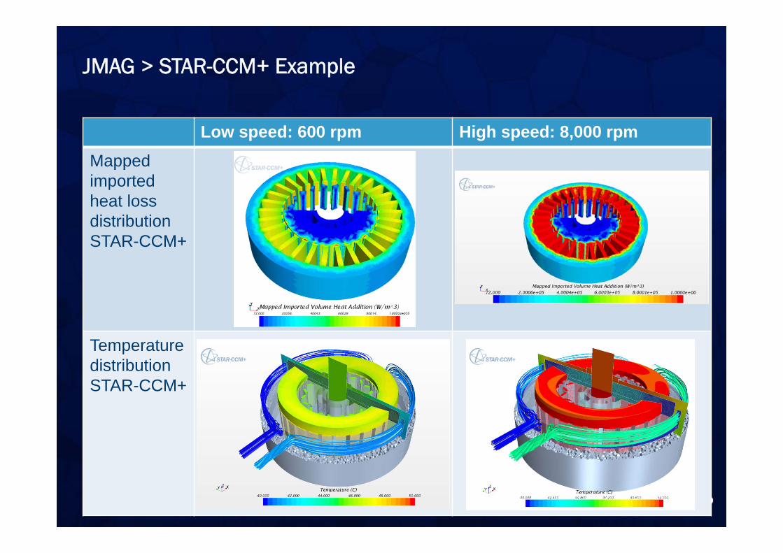
Low speed: 600 rpm High speed: 8,000 rpmMappedimported heat loss distribution STAR-CCM+
Temperature distributionSTAR-CCM+
JMAG > STAR-CCM+ Example
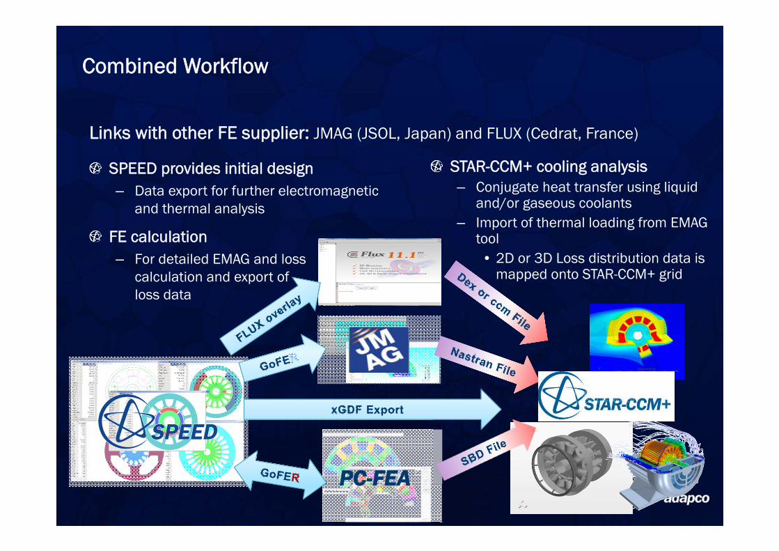
SPEED provides initial design– Data export for further electromagnetic
and thermal analysis
PC-FEA
FE calculation– For detailed EMAG and loss
calculation and export of loss data
STAR-CCM+ cooling analysis– Conjugate heat transfer using liquid
and/or gaseous coolants– Import of thermal loading from EMAG
tool• 2D or 3D Loss distribution data is
mapped onto STAR-CCM+ grid
Combined Workflow
Links with other FE supplier: JMAG (JSOL, Japan) and FLUX (Cedrat, France)
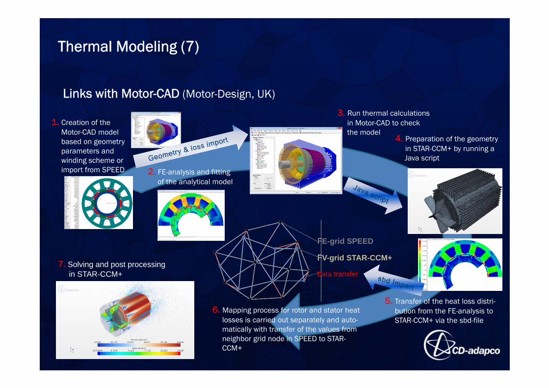
3. Run thermal calculationsin Motor-CAD to checkthe model
2. FE-analysis and fittingof the analytical model
5. Transfer of the heat loss distri-bution from the FE-analysis to STAR-CCM+ via the sbd-file
FE-grid SPEED
FV-grid STAR-CCM+
1. Creation of theMotor-CAD model based on geometry parameters and winding scheme orimport from SPEED
Data transfer
4. Preparation of the geometryin STAR-CCM+ by running a Java script
7. Solving and post processingin STAR-CCM+
6. Mapping process for rotor and stator heatlosses is carried out separately and auto-matically with transfer of the values fromneighbor grid node in SPEED to STAR-CCM+
Thermal Modeling (7)
Links with Motor-CAD (Motor-Design, UK)
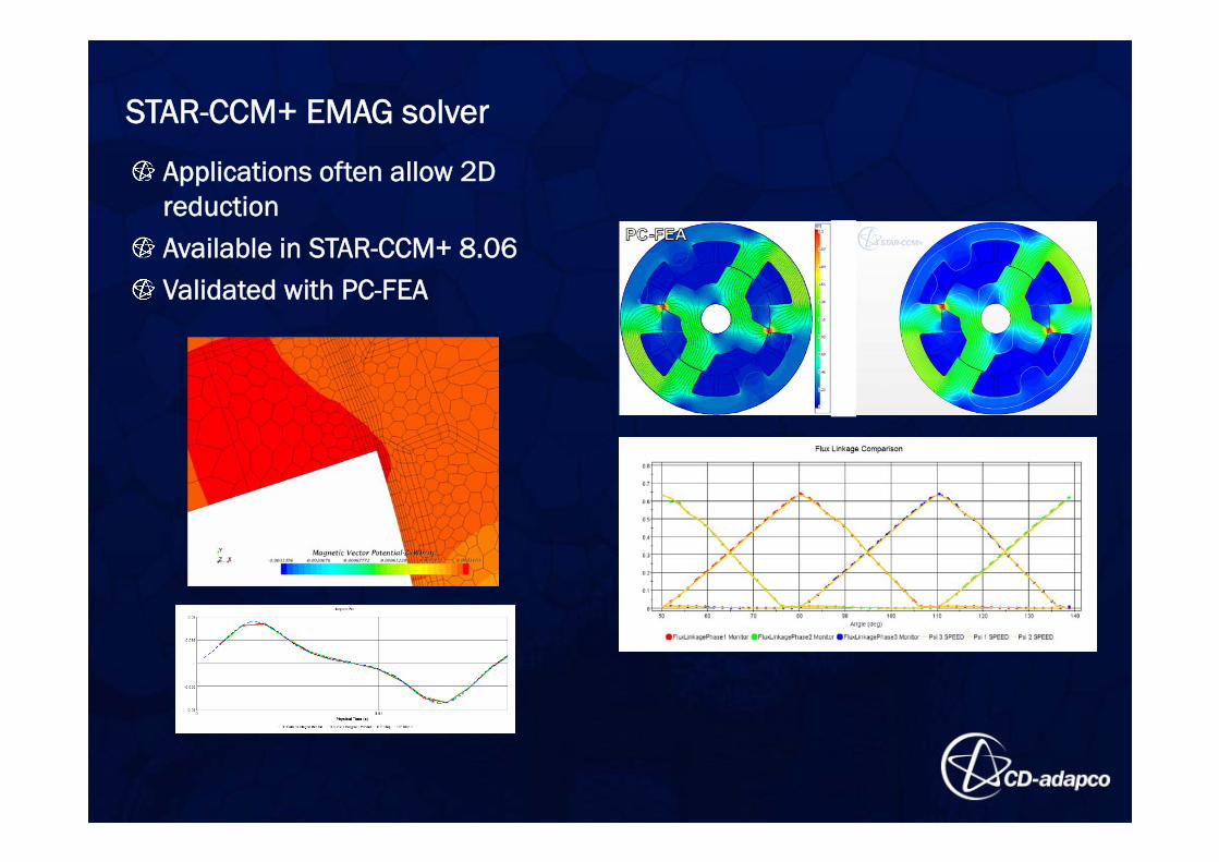
STAR-CCM+ EMAG solver
Applications often allow 2D reductionAvailable in STAR-CCM+ 8.06Validated with PC-FEA
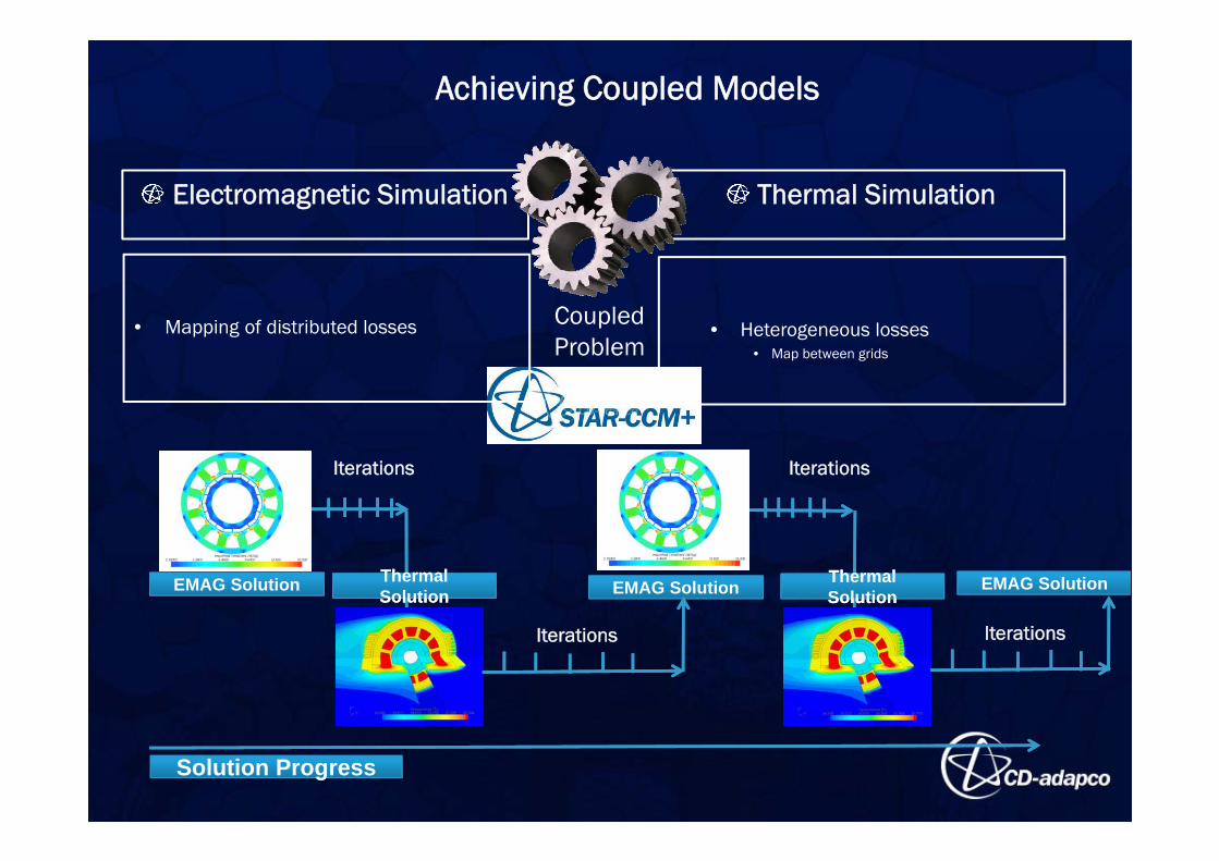
Achieving Coupled Models
Electromagnetic Simulation Thermal Simulation
CoupledProblem
Solution ProgressSolution Progress
EMAG Solution ThermalSolutionThermal Solution EMAG Solution Thermal
SolutionThermal Solution
Iterations
Iterations
Iterations
Iterations
EMAG Solution
• Mapping of distributed losses • Heterogeneous losses• Map between grids

Electric Machine Simulation TechnologySteve Hartridge
Director, Electric & Hybrid Vehicles
Besides CD-adapco internal material this presentation is based on the following publications:
• Bauarten von elektrischen Antrieben und deren Kühlung, Verluste, Vor- und Nachteile, Univ.-Prof. Dr. phil. Dr. techn. habil. Harald Neudorfer, Traktionssysteme Austria GmbH, Kolloquium Elektrische Antriebe in der Landtechnik, Wieselburg, 26. Juni 2013 – Austria
• Keith R Pullen, Professor of Energy Systems, Brunthan Yoheswaren, PhD Researcher Energy and Transport Research Centre School of Engineering and Mathematical Sciences, Cooling of Electrical Machines, EMTM ’13, 12 September 2013 ▪ Nottingham University – UK
• Conjugate Heat Transfer Analysis of Integrated Brushless Generators for More Electric Engines Marco Tosetti, Paolo Maggiore, Andrea Cavagnino, Senior Member IEEE, and Silvio Vaschetto, Member IEEE, Politecnico di Torino, Corso Duca degli Abruzzi 24, 10129 Torino – Italy
• Electric Motor Thermal Management, U.S. Department of Energy, Kevin Pennion, May 11, 2011 – US
• End Winding Cooling in Electrical Machines, Christopher Micallef, BEng (Hons), PhD Thesis submitted to the University of Nottingham, September 2006 –UK
• Script Large Generators & High Power Drives, Prof. habil. Dr.Ing. A. Binder, A., TU Darmstadt, Inst. f. Elektrische Energiewandlung, 2008 – Germany


![ZYBO - Digilent Documentation [Reference.Digilentinc] Z7 B.2 out of 14 2017 MIPI, General I/O 10K R60 10K R62 10K R64 10K R67 GND VCC3V3 SW3 SW2 SW1 SW0 10K R57 10K R71 10K R72 GND](https://img.pdfslide.net/doc/110x75/5abecaa37f8b9a3a428d6851/zybo-digilent-documentation-z7-b2-out-of-14-2017-mipi-general-io-10k-r60.jpg)