Embed Size (px)
Citation preview
2
Electric Motor Performance Improvement Using Auxiliary Windings and Capacitance Injection
Nicolae D.V Tshwane University of Technology
South Africa
1. Introduction
Generally, some electric machines such as induction machines and synchronous reluctance motors require reactive power for operation. While the reactive power required by a synchronous machine can be taken from the power source or supplied by the machine itself by adjustment of the field current, the power factor of an induction machine is always lagging and set by external quantities (i.e., the load and terminal voltage). Poor power factor adversely affects the distribution system and a cost penalty is frequently levied for excessive VAr consumption. Power factor is typically improved by installation of capacitor banks parallel to the motor. If the capacitor bank is fixed (i.e. that it can compensate power factor only for a fixed load), when the load is variable, then the compensation is lost. Some authors (El-Sharkawi et al, 1984, Fuchs and Hanna, 2002) introduced the capacitors using thyristor/triac controllers; by adjusting the firing angle, the capacitance introduced in parallel with the motor becomes variable and thus compensating the power factor for any load. Other works (Suciu et al, 2000.) consider the induction motor as an RL load and power factor is improved by inserting a variable capacitor (through a bridge converter) which is adjusted for unity according with the load. For the above methods, the capacitive injection is directly into the supply. Another method conceived for slip ring induction motor was to inject capacitive reactive power direct into the rotor circuit (Reinert and Parsley, 1995; Suciu, et al. 2002). The injection of reactive power can be done through auxiliary windings magnetically coupled with the main windings (E. Muljadi et al. 1989; Tamrakan and Malik, 1999; Medarametla et al. 1992; Umans, and H. L. Hess, 1983; Jimoh and Nicolae, 2006, 2007). This compensating method has also been applied with good results not only for induction motors but also for a synchronous reluctance motor (Ogunjuyigbe et al. 2010).
2. Method description
2.1 Physical solution
The method described in this chapter makes use of two three-phase stator windings. One set, the main winding (star or delta), is connected directly to the source. The other set of windings - auxiliary, is only magnetically coupled to the main winding. All windings have the same shape and pitch, but may have different turn numbers and wire sizes; usually smaller in order to be accommodated in the slots together with the stator. The windings are
www.intechopen.com
Electric Machines and Drives
26
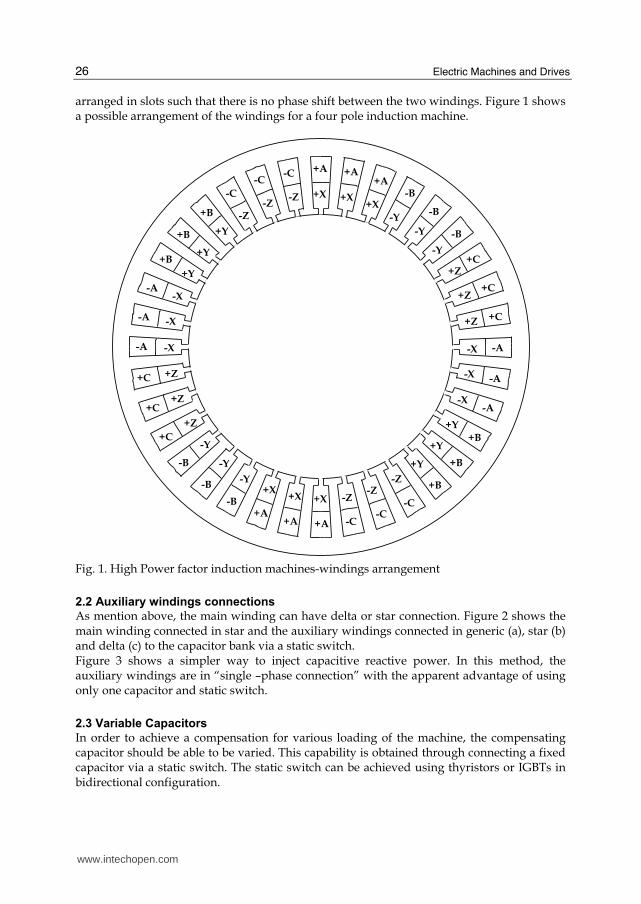
arranged in slots such that there is no phase shift between the two windings. Figure 1 shows a possible arrangement of the windings for a four pole induction machine.
+A +A +A
+X +X +X
-Y
-Y
-B
-B
-B
-Y
+Z
+C
+C
+C
+Z
+Z
-A -X
-X
-X
-A
-A
+B
+Y
+Y
+Y +B
+B
-C
-Z
-C -C
-Z -Z
+A
+X +X +X
+A
+A
-B
-Y
-Y
-Y
-B
-B
+C
+Z
+Z
+Z
+C
+C
-A -X
-X
-X
-A
-A
+B
+Y
+Y
+Y +B
+B
-C
-Z
-Z -Z
-C -C
Fig. 1. High Power factor induction machines-windings arrangement
2.2 Auxiliary windings connections
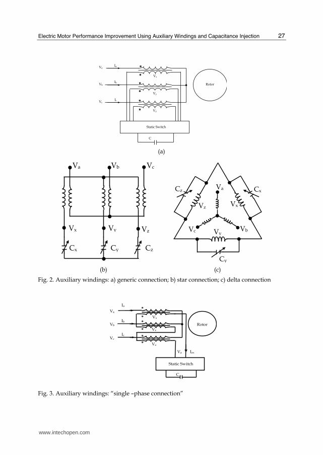
As mention above, the main winding can have delta or star connection. Figure 2 shows the main winding connected in star and the auxiliary windings connected in generic (a), star (b) and delta (c) to the capacitor bank via a static switch. Figure 3 shows a simpler way to inject capacitive reactive power. In this method, the auxiliary windings are in “single –phase connection” with the apparent advantage of using only one capacitor and static switch.
2.3 Variable Capacitors
In order to achieve a compensation for various loading of the machine, the compensating capacitor should be able to be varied. This capability is obtained through connecting a fixed capacitor via a static switch. The static switch can be achieved using thyristors or IGBTs in bidirectional configuration.
www.intechopen.com
Electric Motor Performance Improvement Using Auxiliary Windings and Capacitance Injection
27
Va
Vb
Vc
Rotor
C
Ia
●
Vx
Vy
Vz
Ib
Ic
*
*
*
*
*
*
Static Switch
(a)
●
●● ● ●
●
● ● ●Va Vb Vc
VzVyVx
CzCyCx
●
●
● ●
●
●
Va
Vb Vc
Vx
Vy
Vz
Cx
Cy
Cz
●● ●
●
(b) (c)
Fig. 2. Auxiliary windings: a) generic connection; b) star connection; c) delta connection
Va
Vb
Vc
Va
Rotor
Iax
C
Static Switch
Ia
●Vx
Vy
Vz
Ib
Ic
Fig. 3. Auxiliary windings: “single –phase connection”
www.intechopen.com
Electric Machines and Drives
28
2.3.1 Thyristor-based variable capacitor
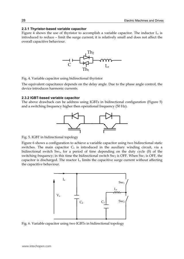
Figure 4 shows the use of thyristor to accomplish a variable capacitor. The inductor Lr is introduced to reduce – limit the surge current; it is relatively small and does not affect the overall capacitive behaviour.
Th1
C Lr
Th2
Fig. 4. Variable capacitor using bidirectional thyristor
The equivalent capacitance depends on the delay angle. Due to the phase angle control, the device introduces harmonic currents.
2.3.2 IGBT-based variable capacitor
The above drawback can be address using IGBTs in bidirectional configuration (Figure 5) and a switching frequency higher then operational frequency (50 Hz).
Fig. 5. IGBT in bidirectional topology
Figure 6 shows a configuration to achieve a variable capacitor using two bidirectional static switches. The main capacitor C1 is introduced in the auxiliary winding circuit, via a bidirectional switch Sw1, for a period of time depending on the duty cycle (├) of the switching frequency; in this time the bidirectional switch Sw2 is OFF. When Sw1 is OFF, the capacitor is discharged. The reactor Lr limits the capacitive surge current without affecting the capacitive behaviour.
C1 C2
Vx
Ix
●
Sw1
Sw2
●●
●
Lr
Fig. 6. Variable capacitor using two IGBTs in bidirectional topology
www.intechopen.com
Electric Motor Performance Improvement Using Auxiliary Windings and Capacitance Injection
29
The capacitor C2, much smaller than C1 is connected to mitigate the voltage spikes during switching off the main capacitor. Thus, the equivalent capacitor can be written as:
eq 1 2C =δ×C +C (1)
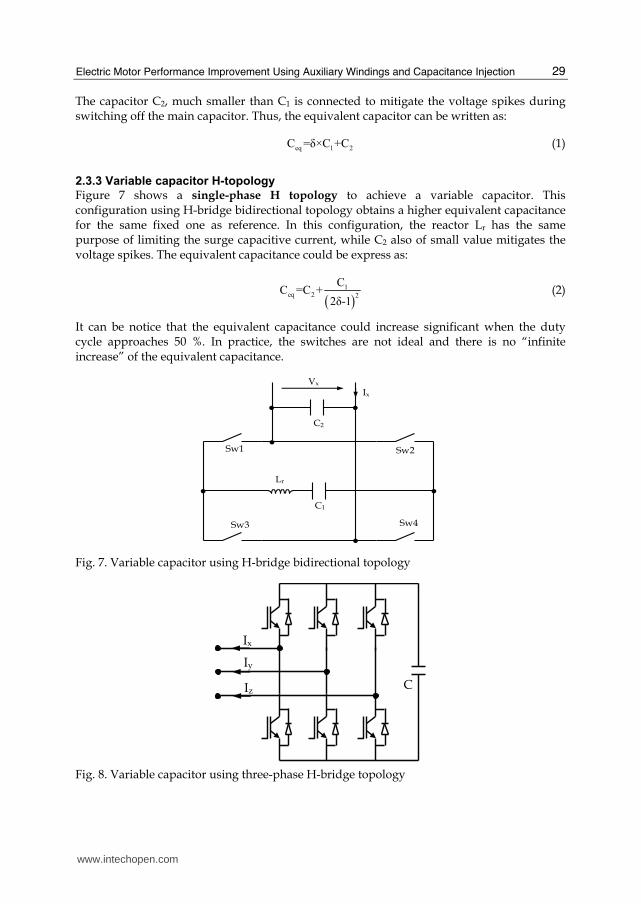
2.3.3 Variable capacitor H-topology
Figure 7 shows a single-phase H topology to achieve a variable capacitor. This configuration using H-bridge bidirectional topology obtains a higher equivalent capacitance for the same fixed one as reference. In this configuration, the reactor Lr has the same purpose of limiting the surge capacitive current, while C2 also of small value mitigates the voltage spikes. The equivalent capacitance could be express as:
( )1eq 2 2
CC =C +
2δ-1 (2)
It can be notice that the equivalent capacitance could increase significant when the duty cycle approaches 50 %. In practice, the switches are not ideal and there is no “infinite increase” of the equivalent capacitance.
●
●
● ●
●
●
Sw1 Sw2
Sw3 Sw4
C1
C2
Vx
Ix
Lr
Fig. 7. Variable capacitor using H-bridge bidirectional topology
C
Iy
Ix
Iz
Fig. 8. Variable capacitor using three-phase H-bridge topology
www.intechopen.com
Electric Machines and Drives
30
Another solution to achieve a variable capacitance, or rather to generate a capacitive current was proposed using a three-phase H topology as PWM inverter (E. Muljadi, et al 1989; Tamrakan and Malik, 1999) as presented in Figure 8. The converter injects capacitive reactive power into auxiliary windings and thus improving the power factor of the motor.
3. Mathematical model
The machine is treated as having two three-phase windings and the voltages equations system can be written as:
abcs 1 abc abc
d[V ]=[R ][I ]+ [λ ]
dt (3)
2 xyz xyz xyz
d0=[R ][I ]+ [λ ]+Vc
dt (2)
r abcr abcr
d0=[R ][I ]+ [λ ]
dt (5)
where
T
abc a b cV = V V V⎡ ⎤⎣ ⎦ (6)
T
abcs a b cI = I I I⎡ ⎤⎣ ⎦ ; T
abc a b cλ = λ λ λ⎡ ⎤⎣ ⎦ (7)
a
1 b
c
r 0 0
[R ]= 0 r 0
0 0 r
⎡ ⎤⎢ ⎥⎢ ⎥⎢ ⎥⎣ ⎦
x
2 y
z
r 0 0
[R ]= 0 r 0
0 0 r
⎡ ⎤⎢ ⎥⎢ ⎥⎢ ⎥⎣ ⎦
(8)
Note that indices “1” refer to the main winding and “2” to the auxiliary winding.
abc abcsxyz abcsrabcs abcs
xyz xyzabcs xyz xyzabcr xyz
abcr abcrs abcrxyz abcr abcr
L L Lλ I
λ = L L L I
λ L L L I
⎡ ⎤⎡ ⎤ ⎡ ⎤⎢ ⎥⎢ ⎥ ⎢ ⎥⎢ ⎥⎢ ⎥ ⎢ ⎥⎢ ⎥⎢ ⎥ ⎢ ⎥⎢ ⎥⎣ ⎦ ⎣ ⎦⎣ ⎦ (9)
The inductances in eq. (9) are time dependent, and this make the equation difficult and time consuming to solve. In order to obtain constant parameters, the voltage equations (3-5) are then transformed to the rotor reference frame. To achieve this, the equations are multiplied with an appropriate transformation matrix K(θ) to obtain:
abcs 1 abcs abcs
d[K(θ)][V ]=[R ][K(θ)][I ]+ [K(θ)][λ ]
dt (10)
2 xyzs xyzs cxyzs
d0=[R ][K(θ)][I ]+ [K(θ)][λ ]+ Kθ V
dt⎡ ⎤⎡ ⎤⎣ ⎦⎣ ⎦ (11)
www.intechopen.com
Electric Motor Performance Improvement Using Auxiliary Windings and Capacitance Injection
31
r r abcr r abcr
d0=[R ][K(θ )][I ]+ [K(θ )][λ ]
dt (12)
When these equations are expanded, after substantial matrix manipulations, it resolves to:
qdo1 s1 qdo1 qd01 qdo1
dV = R I + λ + λ
dt⎡ ⎤ ⎡ ⎤ ⎡ ⎤ ⎡ ⎤ϖ⎡ ⎤⎣ ⎦⎣ ⎦ ⎣ ⎦ ⎣ ⎦ ⎣ ⎦ (13)
2 qdo2 qd02 qdo2 qd02
d0= R I + λ + λ + Vc
dt⎡ ⎤ ⎡ ⎤ ⎡ ⎤ ⎡ ⎤ϖ⎡ ⎤⎣ ⎦⎣ ⎦ ⎣ ⎦ ⎣ ⎦ ⎣ ⎦ (14)
r qdor qd0r r qdo1
d0= R I + λ + λ
dt⎡ ⎤ ⎡ ⎤ ⎡ ⎤ϖ⎡ ⎤⎣ ⎦⎣ ⎦ ⎣ ⎦ ⎣ ⎦ (15)
where
0 1 0
1 0 0
0 0 0
⎡ ⎤⎢ ⎥ϖ = ω −⎢ ⎥⎢ ⎥⎣ ⎦;
0 1 0
( ) 1 0 0
0 0 0
⎡ ⎤⎢ ⎥ϖ = ω−ω −⎢ ⎥⎢ ⎥⎣ ⎦r r
(16)
and
qdo2 qd02 qd02
1Vc = I dt+ Vc
C⎡ ⎤ ⎡ ⎤ ⎡ ⎤ϖ⎣ ⎦ ⎣ ⎦ ⎣ ⎦∫ (17)
Neglecting the ‘0’ sequence since we initially are assuming a balanced system, the expression for the stator and rotor flux linkages, resolves into the matrix:
q1 q1ls1 m lm m m
d1 d1ls1 m lm m m
q2 q2lm m ls2 m m
lm m ls2 m md2 d2
m m lsr mqr qr
m m lsr mdr dr
λ IL +L 0 L +L 0 L 0
λ I0 L +L 0 L +L 0 L
λ IL +L 0 L +L 0 L 0=
0 L +L 0 L +L 0 Lλ I
L 0 L 0 L +L 0λ I
0 L 0 L 0 L +Lλ I
⎡ ⎤ ⎡ ⎤⎡ ⎤⎢ ⎥ ⎢ ⎥⎢ ⎥⎢ ⎥ ⎢ ⎥⎢ ⎥⎢ ⎥ ⎢ ⎥⎢ ⎥⎢ ⎥ ⎢ ⎥⎢ ⎥⎢ ⎥ ⎢ ⎥⎢ ⎥⎢ ⎥ ⎢ ⎥⎢ ⎥⎢ ⎥ ⎢ ⎥⎢ ⎥⎢ ⎥ ⎢ ⎥⎢ ⎥⎣ ⎦⎣ ⎦ ⎣ ⎦
(18)
4. Equivalent model
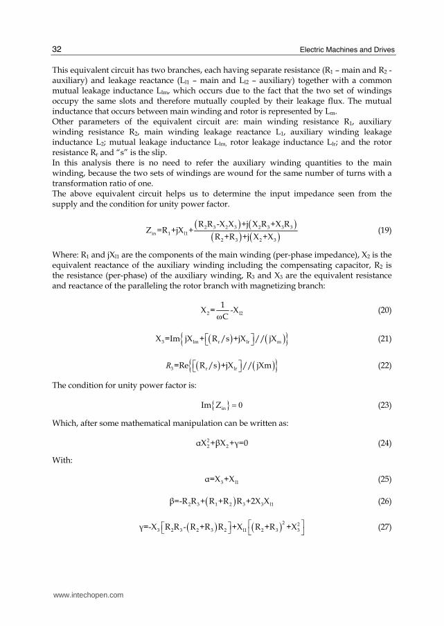
4.1 Symmetrical loaded auxiliary windings When each phase of the auxiliary windings is loaded with equal capacitors (C), eventually star connected, the entire circuit is having a symmetrical behaviour and the equivalent circuit is very simple as shown in Figure 9.
V1
R1
R2 Ll2
Ll1
Llm
Lm
Llr
Rr/s
C
I1
Fig. 9. Equivalent circuit for symmetrical loading auxiliary winding
www.intechopen.com
Electric Machines and Drives
32
This equivalent circuit has two branches, each having separate resistance (R1 – main and R2 - auxiliary) and leakage reactance (Ll1 – main and Ll2 – auxiliary) together with a common mutual leakage inductance Llm, which occurs due to the fact that the two set of windings occupy the same slots and therefore mutually coupled by their leakage flux. The mutual inductance that occurs between main winding and rotor is represented by Lm. Other parameters of the equivalent circuit are: main winding resistance R1, auxiliary winding resistance R2, main winding leakage reactance L1, auxiliary winding leakage inductance L2; mutual leakage inductance Llm, rotor leakage inductance Llr; and the rotor resistance Rr and “s” is the slip. In this analysis there is no need to refer the auxiliary winding quantities to the main winding, because the two sets of windings are wound for the same number of turns with a transformation ratio of one. The above equivalent circuit helps us to determine the input impedance seen from the supply and the condition for unity power factor.
( ) ( )( ) ( )2 3 2 3 2 3 3 3
in 1 l1
2 3 2 3
R R -X X +j X R +X RZ =R +jX +
R +R +j X +X (19)
Where: R1 and jXl1 are the components of the main winding (per-phase impedance), X2 is the equivalent reactance of the auxiliary winding including the compensating capacitor, R2 is the resistance (per-phase) of the auxiliary winding, R3 and X3 are the equivalent resistance and reactance of the paralleling the rotor branch with magnetizing branch:
2 l2
1X = -X
Cω (20)
( ) ( ){ }3 lm r lr mX =Im jX + R /s +jX // jX⎡ ⎤⎣ ⎦ (21)
( ) ( ){ }3 r lr=Re R /s +jX // jXm⎡ ⎤⎣ ⎦R (22)
The condition for unity power factor is:
{ } 0inIm Z = (23)
Which, after some mathematical manipulation can be written as:
22 2┙X +┚X +┛=0 (24)
With:
3 l1┙=X +X (25)
( )2 3 1 2 3 3 l1┚=-R R + R +R R +2X X (26)
( ) ( )2 23 2 3 2 3 2 l1 2 3 3┛=-X R R - R +R R +X R +R +X⎡ ⎤⎡ ⎤⎣ ⎦ ⎣ ⎦ (27)
www.intechopen.com
Electric Motor Performance Improvement Using Auxiliary Windings and Capacitance Injection
33
The equation (24) together with relations (25) to (27) produces two solutions, which means for a given slip (s) there are two values for the capacitor satisfying the condition for unity power factor. The practical/recommended value is the high X2 or small C connected to the auxiliary winding in order to have a small current through it.
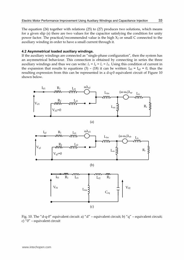
4.2 Asymmetrical loaded auxiliary windings.
If the auxiliary windings are connected as “single-phase configuration”, then the system has an asymmetrical behaviour. This connection is obtained by connecting in series the three auxiliary windings and thus we can write: Ix = Iy = Iz = IX. Using this condition of current in the expansion that results to equations (3) – (18) it can be written: Id2 = Iq2 = 0, thus the resulting expression from this can be represented in a d-q-0 equivalent circuit of Figure 10 shown below.
Lm
Ll1 R1ωλq1
(ω-ωr)λqr
Vd1
Llm Llr
Rr
R2 Ll2
Id1
Vd2=0
(a)
Lm
Ll1 R1ωλd1
(ω-ωr)λdr
Vq1
Llm Llr
Rr
R2 Ll2
Iq1
Vq2=0
(b)
I01 Ll2 Ll1
V01
R2
Llm V02
Ceq
R1
(c)
Fig. 10. The “d-q-0” equivalent circuit: a) “d” – equivalent circuit; b) “q” – equivalent circuit; c) “0” – equivalent circuit
www.intechopen.com
Electric Machines and Drives
34
The particularity of connecting the auxiliary windings in a single phase winding creates an asymmetrical situation which brings about the relevance of the zero sequence. The power factor of the machine could be defined by the argument of Za, which is Va/Ia. And this is expressed as:
q1 01aa
a q1 01
V +VVZ = =
I I +I (28)
01 lm01 02 02
lm
(Z +Z )V (C)=(-jωC+Z )×I ×
Z (29)
As can be observed from the equations (28) and (29), the power factor of the machine depends on C and thus it can be brought to unity by means of adjusting the equivalent capacitance. It should be also noticed that the asymmetrical behaviour of the auxiliary windings connected as “single-phase configuration” has got a significant draw-back namely creating torque ripple. This disadvantage should not be overseen by the simplicity of the physical solution. Given this, further in this, we will consider only the symmetrical loading of the auxiliary winding.
5. Concept validation
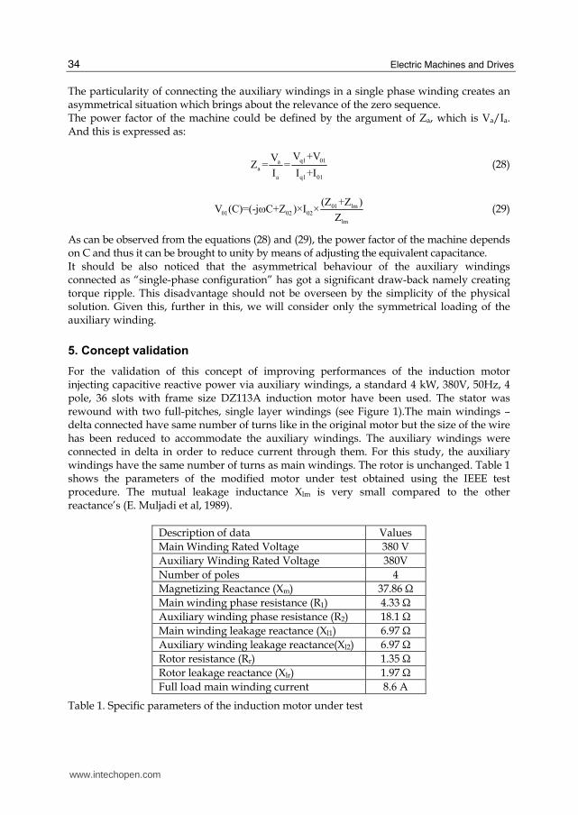
For the validation of this concept of improving performances of the induction motor injecting capacitive reactive power via auxiliary windings, a standard 4 kW, 380V, 50Hz, 4 pole, 36 slots with frame size DZ113A induction motor have been used. The stator was rewound with two full-pitches, single layer windings (see Figure 1).The main windings – delta connected have same number of turns like in the original motor but the size of the wire has been reduced to accommodate the auxiliary windings. The auxiliary windings were connected in delta in order to reduce current through them. For this study, the auxiliary windings have the same number of turns as main windings. The rotor is unchanged. Table 1 shows the parameters of the modified motor under test obtained using the IEEE test procedure. The mutual leakage inductance Xlm is very small compared to the other reactance’s (E. Muljadi et al, 1989).
Description of data Values
Main Winding Rated Voltage 380 V
Auxiliary Winding Rated Voltage 380V
Number of poles 4
Magnetizing Reactance (Xm) 37.86 Ω
Main winding phase resistance (R1) 4.33 Ω
Auxiliary winding phase resistance (R2) 18.1 Ω
Main winding leakage reactance (Xl1) 6.97 Ω
Auxiliary winding leakage reactance(Xl2) 6.97 Ω
Rotor resistance (Rr) 1.35 Ω
Rotor leakage reactance (Xlr) 1.97 Ω
Full load main winding current 8.6 A
Table 1. Specific parameters of the induction motor under test
www.intechopen.com
Electric Motor Performance Improvement Using Auxiliary Windings and Capacitance Injection
35
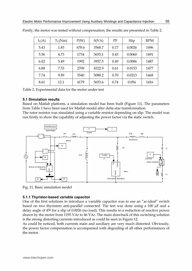
Firstly, the motor was tested without compensation; the results are presented in Table 2.
IL(A) TL(Nm) P(W) S(VA) PF Slip RPM
5.43 1.83 678.6 3568.7 0.17 0.0026 1496
5.56 4.73 1734 3655.1 0.43 0.0060 1491
6.02 5.49 1992 3957.5 0.49 0.0086 1487
6.88 7.53 2709 4522.9 0.61 0.0153 1477
7.74 9.89 3540 5088.2 0.70 0.0213 1468
8.61 12.1 4179 5653.6 0.74 0.056 1416
Table 2. Experimental data for the motor under test
5.1 Simulation results
Based on Matlab platform, a simulation model has been built (Figure 11). The parameters from Table 1 have been used for Matlab model after delta-star transformation. The rotor resistor was simulated using a variable resistor depending on slip. The model was run firstly to show the capability of adjusting the power factor via the static switch.
Main
s
Xm
Xr
Rr/s
R1 Xl1 Xl2 R2
Control
C
Auxil iary
(Variable Resistor)
Lr
Continuous
pow ergui
v+-
Q P
Va
Ia
t
In1
Conn1
Conn2
gm
12
Ideal Switch
i+
-
00.056
0
Clock
V IP
Q
Active & Reactive
Power
Fig. 11. Basic simulation model
5.1.1 Thyristor-based variable capacitor
One of the first solutions to introduce a variable capacitor was to use an “ac-ideal” switch based on two thyristors anti-parallel connected. The test was done using a 100 µF and a delay angle of 450 for a slip of 0.0026 (no load). This results in a reduction of reactive power drawn by the motor from 1193 VAr to 46 VAr. The main drawback of this switching solution is the strong distorting currents introduced as could be seen in Figure 12. As could be noticed, both currents main and auxiliary are very much distorted. Obviously, the power factor compensation is accompanied with degrading of all other performances of the motor.
www.intechopen.com
Electric Machines and Drives
36
0.145 0.15 0.155 0.16 0.165 0.17 0.175 0.18
-300
-200
-100
0
100
200
300
Time (sec)
Rela
tive a
mplitude (V, A)
va (t)
ia (t)*10
ix (t)*10
Fig. 12. Electric parameters (va, ia and ix) for compensated model using thyristor-based variable capacitor
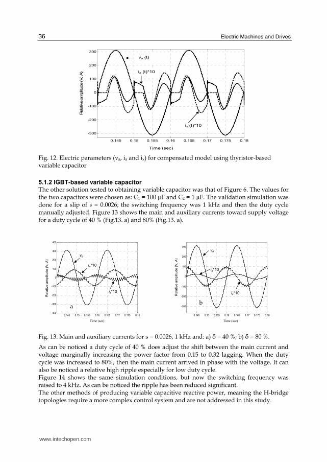
5.1.2 IGBT-based variable capacitor
The other solution tested to obtaining variable capacitor was that of Figure 6. The values for the two capacitors were chosen as: C1 = 100 µF and C2 = 1 µF. The validation simulation was done for a slip of s = 0.0026; the switching frequency was 1 kHz and then the duty cycle manually adjusted. Figure 13 shows the main and auxiliary currents toward supply voltage for a duty cycle of 40 % (Fig.13. a) and 80% (Fig.13. a).
Fig. 13. Main and auxiliary currents for s = 0.0026, 1 kHz and: a) ├ = 40 %; b) ├ = 80 %.
As can be noticed a duty cycle of 40 % does adjust the shift between the main current and voltage marginally increasing the power factor from 0.15 to 0.32 lagging. When the duty cycle was increased to 80%, then the main current arrived in phase with the voltage. It can also be noticed a relative high ripple especially for low duty cycle. Figure 14 shows the same simulation conditions, but now the switching frequency was raised to 4 kHz. As can be noticed the ripple has been reduced significant. The other methods of producing variable capacitive reactive power, meaning the H-bridge topologies require a more complex control system and are not addressed in this study.
0.145 0.15 0.155 0.16 0.165 0.17 0.175 0.18-400
-300
-200
-100
0
100
200
300
400
Rela
tive a
mp
litud
e (
V,
A)
a
ia*10
ix*10
va
Time (sec)
0.145 0.15 0.155 0.16 0.165 0.17 0.175 0.18
-300
-200
-100
0
100
200
300
Rela
tive a
mp
litud
e (
V,
A)
b
va
ia*10
ix*10
Time (sec)
www.intechopen.com

Electric Motor Performance Improvement Using Auxiliary Windings and Capacitance Injection
37
Fig. 14. Main and auxiliary currents for s = 0.0026, 4 kHz and: a) ├ = 40 %; b) ├ = 80 %.
5.1.3 Capacitance versus slip for unity power factor
Now, the model was run for each value of the slip (speed) given in Table 2. The result of these simulations is the capacitance producing unity power factor (see Table 3).
s (n)
CY (µF)
Ia (A)
Pa
(W) Qa
(VAr) Sa
(VA) PF
0 5.49 184 1193 1207 0.152 0.0026 (1496) 81 1.65 362 9 363 0.999
0 5.65 366 1187 1242 0.295 0.006 (1491) 81 2.57 565 11 565 0.999
0 5.86 505 1186 1289 0.392 0.0086 (1487) 81.6 3.27 718 15 719 0.999
0 6.71 855 1200 1473 0.58 0.0153 (1477) 87 5.21 1143 1 1143 0.999
0 7.68 1160 1229 1689 0.686 0.0213 (1468) 90 6.82 1499 17 1499 0.999
0 8.31 1330 1252 1826 0.728 0.056 (1491) 90.6 7.66 1684 27 1686 0.999
Table 3. Simulation results: capacitance versus slip for unity power factor
It is interesting to observe that the capacitance producing unity power factor does not vary
so much as presented in other studies (E. Muljadi et al. 1989; Tamrakan and Malik, 1999)
concerning similar method of injecting capacitive reactive power.
Moreover, it could be found a fix value of 75 µF which maintain a high power factor
irrespective of the load/slip. Table 4 shows the simulation results for the fixed capacitor and
variable load/slip.
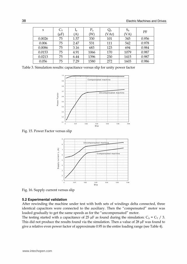
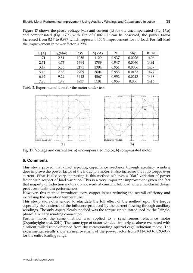
Figure 15 shows the variation of the power factor versus slip and Figure 16 shows the
variation of the supply current versus slip for compensated with a fix 75 µF capacitor per
phase and uncompensated machine.
0.145 0.15 0.155 0.16 0.165 0.17 0.175 0.18-400
-300
-200
-100
0
100
200
300
400
Rel
ativ
e am
pli
tud
e (V
, A
)
va
ix*10
ia*10
Time (sec)
0.145 0.15 0.155 0.16 0.165 0.17 0.175 0.18-400
-300
-200
-100
0
100
200
300
400
Rel
ativ
e am
pli
tud
e (V
, A
)
va
ia*10
ix*10
Time (sec)
www.intechopen.com
Electric Machines and Drives
38
s
CY (µF)
Ia (A)
Pa
(W) Qa
(VAr) Sa
(VA) PF
0.0026 75 1.57 330 101 345 0.956
0.006 75 2.47 531 111 542 0.978
0.0086 75 3.16 683 123 694 0.984
0.0153 75 4.91 1066 170 1079 0.987
0.0213 75 6.44 1396 230 1415 0.987
0.056 75 7.29 1580 272 1603 0.986
Table 3. Simulation results: capacitance versus slip for unity power factor
●
●
●
●
●
●
●● ● ● ● ●
Po
we
r F
ac
tor
0.1
0.2
0.3
0.4
0.5
0.6
0.7
0.8
0.9
1.0
0 0.06 0.05 0.04 0.03 0.02 0.01
●
Sl ip
Unc omp ens at ed mach i n e
C omp ens at ed mac hi n e
Fig. 15. Power Factor versus slip
●
●
●
●
●
●
●
Su
pp
ly c
urr
en
t I a
(A
)
1
2
3
4
5
6
7
8
0 0.06 0.05 0.04 0.03 0.02 0.01
Sl ip
Unc ompens at ed mach i ne
C om pens at ed mac hine
●●
●
●
●
9
Fig. 16. Supply current versus slip
5.2 Experimental validation
After rewinding the machine under test with both sets of windings delta connected, three
identical capacitors were connected to the auxiliary. Then the “compensated” motor was
loaded gradually to get the same speeds as for the “uncompensated” motor.
The testing started with a capacitance of 25 µF as found during the simulation: CΔ = CY / 3.
This did not produce the results found via the simulation. Then a value of 28 µF was found to
give a relative even power factor of approximate 0.95 in the entire loading range (see Table 4).
www.intechopen.com
Electric Motor Performance Improvement Using Auxiliary Windings and Capacitance Injection
39
Figure 17 shows the phase voltage (van) and current (ia) for the uncompensated (Fig. 17.a) and compensated (Fig. 17.b) with slip of 0.0026. It can be observed, the power factor increased from 0.17 to 0.937 which represent 450% improvement for no load. For full load the improvement in power factor is 29%.
IL(A) TL(Nm) P(W) S(VA) PF Slip RPM
1.71 2.81 1058 1129 0.937 0.0026 1496
2.71 4.73 1694 1789 0.947 0.0060 1491
3.49 5.83 2191 2304 0.951 0.0086 1487
5.46 7.63 2709 3604 0.955 0.0153 1477
6.92 9.29 3442 4567 0.952 0.0213 1468
7.85 13.8 4937 5181 0.953 0.056 1416
Table 2. Experimental data for the motor under test
1) [THS720P].CH1 100 V 2 mS
2) [THS720P].CH2 5 A 2 mS
. . . . . . . . . . . . . . . . . . . . . . . . . . . . . . . . . . . . . . . . . . . .
. . . . . . . . . . . . . . . . . . . . . . . . . . . . . . . . . . . . . . . . . . . .
. . . . . . . . . . . . . . . . . . . . . . . . . . . . . . . . . . . . . . . . . . . .
. . . . . . . . . . . . . . . . . . . . . . . . . . . . . . . . . . . . . . . . . . . . . .
. . . . . . . . . . . . . . . . . . . . . . . . . . . . . . . . . . . . . . . . . . . . . .
. . . . . . . . . . . . . . . . . . . . . . . . . . . . . . . . . . . . . . . . . . . . . .
.
. .
. .
. .
.
.
.
.
.
.
.
.
.
.
.
.
.
. .
.
.
.
.
.
.
.
.
.
.
.
.
.
.
.
.
.
. .
. .
. .
.
.
.
.
.
.
.
.
.
.
.
.
.
.
.
.
. .
.
.
.
.
.
.
.
.
.
.
.
.
.
.
.
.
.
.
.
.
.
.
.
.
.
.
.
.
.
.
.
.
.
.
.
.
.
.
.
.
.
.
.
.
.
.
.
.
.
.
.
.
.
.
.
.
.
.
.
.
.
.
.
.
.
.
.
.
.
.
.
.
.
.
.
.
.
.
.
.
.
.
.
.
.
.
.
.
.
.
.
.
.
.
.
.
.
.
.
.
.
.
.
.
.
.
.
.
.
.
.
.
.
.
.
.
.
.
.
.
.
.
.
.
.
.
.
.
.
.
.
.
.
.
.
.
.
.
.
.
.
.
.
.
.
.
.
.
.
.
.
.
.
.
.
.
.
.
.
.
.
.
.
.
.
.
.
.
.
.
.
.
.
.
.
.
.
.
.
.
.
.
.
.
.
.
.
.
.
.
.
.
.
.
.
.
.
.
.
.
.
.
.
.
.
.
.
.
.
.
.
.
.
.
.
.
.
.
.
.
.
.
.
.
.
.
.
.
.
.
.
.
.
.
.
.
.
.
.
.
.
.
.
.
.
.
.
.
.
.
.
.
.
.
.
.
.
. . . . . . . .
1) [THS720P].CH1 100 V 5 mS 2) [THS720P].CH2 1 A 5 mS
. . . . . . . . . . . . . . . . . . . . . . . . . . . . . . . . . . . . . . . . . . . .
. . . . . . . . . . . . . . . . . . . . . . . . . . . . . . . . . . . . . . . . . . . .
. . . . . . . . . . . . . . . . . . . . . . . . . . . . . . . . . . . . . . . . . . . .
. . . . . . . . . . . . . . . . . . . . . . . . . . . . . . . . . . . . . . . . . . . . . .
. . . . . . . . . . . . . . . . . . . . . . . . . . . . . . . . . . . . . . . . . . . . . .
. . . . . . . . . . . . . . . . . . . . . . . . . . . . . . . . . . . . . . . . . . . . . .
.
. .
. .
. .
.
.
.
.
.
.
.
.
.
.
.
.
.
..
.
.
.
.
.
.
.
.
.
.
.
.
.
.
.
.
.
. .
. .
. .
.
.
.
.
.
.
.
.
.
.
.
.
.
.
.
.
..
.
.
.
.
.
.
.
.
.
.
.
.
.
.
.
.
.
.
.
.
.
.
.
.
.
.
.
.
.
.
.
.
.
.
.
.
.
.
.
.
.
.
.
.
.
.
.
.
.
.
.
.
.
.
.
.
.
.
.
.
.
.
.
.
.
.
.
.
.
.
.
.
.
.
.
.
.
.
.
.
.
.
.
.
.
.
.
.
.
.
.
.
.
.
.
.
.
.
.
.
.
.
.
.
.
.
.
.
.
.
.
.
.
.
.
.
.
.
.
.
.
.
.
.
.
.
.
.
.
.
.
.
.
.
.
.
.
.
.
.
.
.
.
.
.
.
.
.
.
.
.
.
.
.
.
.
.
.
.
.
.
.
.
.
.
.
.
.
.
.
.
.
.
.
.
.
.
.
.
.
.
.
.
.
.
.
.
.
.
.
.
.
.
.
.
.
.
.
.
.
.
.
.
.
.
.
.
.
.
.
.
.
.
.
.
.
.
.
.
.
.
.
.
.
.
.
.
.
.
.
.
.
.
.
.
.
.
.
.
.
.
.
.
.
.
.
.
.
.
.
.
.
.
.
.
.
.
. . . . . . . .
(a) (b)
Fig. 17. Voltage and current for: a) uncompensated motor; b) compensated motor
6. Comments
This study proved that direct injecting capacitance reactance through auxiliary winding does improve the power factor of the induction motor; it also increases the ratio torque over current. What is also very interesting is this method achieves a “flat” variation of power factor with respect of load variation. This is a very important improvement given the fact that majority of induction motors do not work at constant full load where the classic design produces maximum performances. However, this method introduces extra copper losses reducing the overall efficiency and increasing the operation temperature. This study did not intended to elucidate the full effect of the method upon the torque especially the existence of the influence produced by the current flowing through auxiliary windings. The only aspect clearly noticed was the torque ripple introduced by the “single-phase” auxiliary winding connection. Further more, the same method was applied to a synchronous reluctance motor (Ogunjuyigbe et al, 2010). The same type of stator winded similarly as above was used with a salient milled rotor obtained from the corresponding squirrel cage induction motor. The experimental results show an improvement of the power factor from 0.41-0.69 to 0.93-0.97 for the entire loading range.
va
ia
va
ia
www.intechopen.com

Electric Machines and Drives
40
The economic benefits are related with the savings on demand especially for places where a large number of three-phase induction motors are used under variable loading.
7. References
M. A El-Sharkawi, S. S Venkata, T. J Williams, and N. G Butler, “An adaptive Power Factor Controller for Three-Phase Induction Generators”, Paper 84 SM 672-2 presented at the IEEE/PES Summer Meeting, Seattle, Washington, July 15-20, 1984.
Fuchs, E.F. Hanna, W.J.; “Measured efficiency improvements of induction motors with thyristor/triac controllers”, , IEEE Transaction on Energy Conversion, Volume 17, Issue 4, Dec. 2002 pp. 437 – 444
Suciu, C.; Dafinca, L.; Kansara, M.; Margineanu, I.; “Switched capacitor fuzzy control for power factor correction in inductive circuits”, IEEE 31st Annual Power Electronics Specialists Conference, 2000. Vol. 2, pp. 773 - 777
C. Suciu, M. Kansara, P. Holmes and W. Szabo, “Performance Enhancement of an Induction Motor by Secondary Impedance Control, IEEE Trans. On Energy Conversion, Vol. 17, No. 2, June 2002
J. Reinert, M.J. Parsley, ‘‘Controlling the speed of 8×1 induction motor by resonating the rotor &wit,” in IEEE Transactions on Industry Applications, Vol. 31, No. 4, July/August 1995, pp. 887-891.
E. Muljadi, T.A. Lipo, D.W. Novotny, "Power Factor Enhancement of Induction Machines by Means of Solid State Excitation," IEEE Trans. on Power Electronics, Vol. 4, No. 4, pp. 409418, Oct. 1989.
I. M Tamrakan and O.P Malik, “Power Factor Correction of Induction motors Using PWM Inverter Fed Auxiliary Stator Winding”, IEEE Transaction on Energy Conversion, Vol. 14, No.3, Sept, 1999, pp. 426-432
J. B. Medarametla, M. D. Cos, and Baghzouz, “Calculations and measurement of unity plus three-phase induction motor,” IEEE Transactions on Energy Conversion, vol. 7, no. 4, pp. 732-738, 1992.
S. D. Umans, and H. L. Hess, “Modelling and analysis of a the Wanlass three-phase induction motor configuration,” IEEE Transaction on Power Apparatus and Systems, vol. 102, no. 9, pp. 2912-2916, 1983.
R. Spée and A. Wanllace, “Comparative Evaluation Of Power-Factor Improvement Techniques For Squirrel cage Induction Motors”, Industry Applications Society Annual Meeting, 1990.
A.A. Jimoh and D.V. Nicolae, “Performance Analysis of a Three-Phase Induction Motor with Capacitance Injection”, OPTIM’06, 10th International Conference on Optimization of Electrical and Electronic Equipments, Brasov, Romania, May 17-20, 2006
D.V. Nicolae and A.A. Jimoh, “Three-Phase Induction Motor with Power Electronic Controlled Single-Phase Auxiliary Stator Winding”, PESC’07, The 38th IEEE Power Electronics Specialists Conference, Orlando, USA, June 17-21, 2007
A.S.O. Ogunjuyigbe, A.A. Jimoh, D.V. Nicolae and E.S. Obe, “Analysis of Synchronous Reluctance Machine with Magnetically Coupled Three Phase Windings and Reactive Power compensation”, IET Electric Power Applications, 2010, Vol. 4, Iss. 4, pp 291-303
www.intechopen.com
Electric Machines and DrivesEdited by Dr. Miroslav Chomat
ISBN 978-953-307-548-8Hard cover, 262 pagesPublisher InTechPublished online 28, February, 2011Published in print edition February, 2011
InTech EuropeUniversity Campus STeP Ri Slavka Krautzeka 83/A 51000 Rijeka, Croatia Phone: +385 (51) 770 447 Fax: +385 (51) 686 166www.intechopen.com
InTech ChinaUnit 405, Office Block, Hotel Equatorial Shanghai No.65, Yan An Road (West), Shanghai, 200040, China
Phone: +86-21-62489820 Fax: +86-21-62489821
The subject of this book is an important and diverse field of electric machines and drives. The twelve chaptersof the book written by renowned authors, both academics and practitioners, cover a large part of the field ofelectric machines and drives. Various types of electric machines, including three-phase and single-phaseinduction machines or doubly fed machines, are addressed. Most of the chapters focus on modern controlmethods of induction-machine drives, such as vector and direct torque control. Among others, the bookaddresses sensorless control techniques, modulation strategies, parameter identification, artificial intelligence,operation under harsh or failure conditions, and modelling of electric or magnetic quantities in electricmachines. Several chapters give an insight into the problem of minimizing losses in electric machines andincreasing the overall energy efficiency of electric drives.
How to referenceIn order to correctly reference this scholarly work, feel free to copy and paste the following:
Nicolae D.V (2011). Electric Motor Performance Improvement Using Auxiliary Windings and CapacitanceInjection, Electric Machines and Drives, Dr. Miroslav Chomat (Ed.), ISBN: 978-953-307-548-8, InTech,Available from: http://www.intechopen.com/books/electric-machines-and-drives/electric-motor-performance-improvement-using-auxiliary-windings-and-capacitance-injection