Embed Size (px)
Citation preview
NREL is a national laboratory of the U.S. Department of Energy Office of Energy Efficiency & Renewable Energy Operated by the Alliance for Sustainable Energy, LLC
This report is available at no cost from the National Renewable Energy Laboratory (NREL) at www.nrel.gov/publications.
Contract No. DE-AC36-08GO28308
Electric Motor Thermal Management Research Annual Progress Report Kevin Bennion
Management Report NREL/MP-5400-67121 October 2017
NREL is a national laboratory of the U.S. Department of Energy Office of Energy Efficiency & Renewable Energy Operated by the Alliance for Sustainable Energy, LLC
This report is available at no cost from the National Renewable Energy Laboratory (NREL) at www.nrel.gov/publications.
Contract No. DE-AC36-08GO28308
National Renewable Energy Laboratory 15013 Denver West Parkway Golden, CO 80401 303-275-3000 • www.nrel.gov
Electric Motor Thermal Management Research Annual Progress Report Kevin Bennion
Management Report NREL/MP-5400-67121 October 2017
NOTICE
This report was prepared as an account of work sponsored by an agency of the United States government. Neither the United States government nor any agency thereof, nor any of their employees, makes any warranty, express or implied, or assumes any legal liability or responsibility for the accuracy, completeness, or usefulness of any information, apparatus, product, or process disclosed, or represents that its use would not infringe privately owned rights. Reference herein to any specific commercial product, process, or service by trade name, trademark, manufacturer, or otherwise does not necessarily constitute or imply its endorsement, recommendation, or favoring by the United States government or any agency thereof. The views and opinions of authors expressed herein do not necessarily state or reflect those of the United States government or any agency thereof.
Cover Photos by Dennis Schroeder: (left to right) NREL 26173, NREL 18302, NREL 19758, NREL 29642, NREL 19795.
NREL prints on paper that contains recycled content.
1
Electric Motor Thermal Management Research
Principal Investigator: Kevin Bennion National Renewable Energy Laboratory Transportation and Hydrogen Systems Center 15013 Denver West Parkway Golden, CO 80401 Phone: (303) 275-4447 E-mail: [email protected] DOE Technology Development Manager: Susan A. Rogers U.S. Department of Energy 1000 Independence Ave. SW EE-3V Washington, DC 20585 Phone: 202-586-8997 E-mail: [email protected] NREL Task Leader: Sreekant Narumanchi Phone: 303-275-4062 Email: [email protected] Contractor: Contract No.:
Abstract/Executive Summary With the push to reduce component volumes, lower costs, and reduce weight without sacrificing performance or reliability, the challenges associated with thermal management increase for power electronics and electric motors. Thermal management for electric motors will become more important as the automotive industry continues the transition to more electrically dominant vehicle propulsion systems. The transition to such systems leads to higher-power duty cycles for electric-drive systems. Thermal constraints place significant limitations on how electric motors ultimately perform, and as thermal management improves, there will be direct tradeoffs among motor performance, efficiency, cost, and the sizing of electric motors to operate within the thermal constraints.
The goal of this research project is to support broad industry demand for data, analysis methods, and experimental techniques to improve and better understand motor thermal management. Work in FY16 focused on two areas related to motor thermal management: passive thermal performance and active convective cooling. Passive thermal performance emphasized the thermal impact of materials and thermal interfaces among materials within an assembled motor. Active convective cooling focused on measuring convective heat-transfer coefficients using automatic transmission fluid (ATF).
Accomplishments ● Completed construction of experimental test apparatus to measure large-scale variation in ATF
convective heat transfer coefficients
● Completed measurement of fan jet nozzle for ATF heat transfer in collaboration with industry partner
● In collaboration with Oak Ridge National Laboratory (ORNL), performed measurements and analysis of slot winding materials and submitted a manuscript summarizing the results to a journal for potential publication
● In collaboration with Ames Laboratory, performed measurements of mechanical and thermal properties of new magnet materials.
2
Introduction
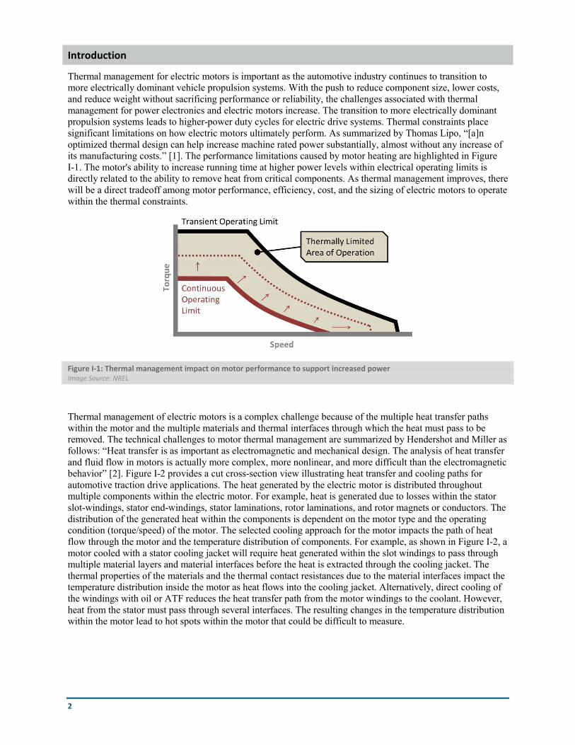
Thermal management for electric motors is important as the automotive industry continues to transition to more electrically dominant vehicle propulsion systems. With the push to reduce component size, lower costs, and reduce weight without sacrificing performance or reliability, the challenges associated with thermal management for power electronics and electric motors increase. The transition to more electrically dominant propulsion systems leads to higher-power duty cycles for electric drive systems. Thermal constraints place significant limitations on how electric motors ultimately perform. As summarized by Thomas Lipo, “[a]n optimized thermal design can help increase machine rated power substantially, almost without any increase of its manufacturing costs.” [1]. The performance limitations caused by motor heating are highlighted in Figure I-1. The motor's ability to increase running time at higher power levels within electrical operating limits is directly related to the ability to remove heat from critical components. As thermal management improves, there will be a direct tradeoff among motor performance, efficiency, cost, and the sizing of electric motors to operate within the thermal constraints.
Figure I-1: Thermal management impact on motor performance to support increased power Image Source: NREL
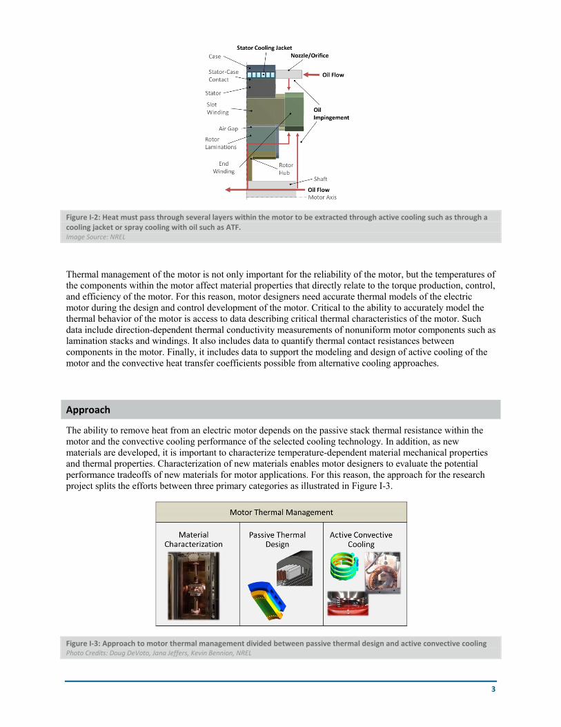
Thermal management of electric motors is a complex challenge because of the multiple heat transfer paths within the motor and the multiple materials and thermal interfaces through which the heat must pass to be removed. The technical challenges to motor thermal management are summarized by Hendershot and Miller as follows: “Heat transfer is as important as electromagnetic and mechanical design. The analysis of heat transfer and fluid flow in motors is actually more complex, more nonlinear, and more difficult than the electromagnetic behavior” [2]. Figure I-2 provides a cut cross-section view illustrating heat transfer and cooling paths for automotive traction drive applications. The heat generated by the electric motor is distributed throughout multiple components within the electric motor. For example, heat is generated due to losses within the stator slot-windings, stator end-windings, stator laminations, rotor laminations, and rotor magnets or conductors. The distribution of the generated heat within the components is dependent on the motor type and the operating condition (torque/speed) of the motor. The selected cooling approach for the motor impacts the path of heat flow through the motor and the temperature distribution of components. For example, as shown in Figure I-2, a motor cooled with a stator cooling jacket will require heat generated within the slot windings to pass through multiple material layers and material interfaces before the heat is extracted through the cooling jacket. The thermal properties of the materials and the thermal contact resistances due to the material interfaces impact the temperature distribution inside the motor as heat flows into the cooling jacket. Alternatively, direct cooling of the windings with oil or ATF reduces the heat transfer path from the motor windings to the coolant. However, heat from the stator must pass through several interfaces. The resulting changes in the temperature distribution within the motor lead to hot spots within the motor that could be difficult to measure.
3
Figure I-2: Heat must pass through several layers within the motor to be extracted through active cooling such as through a cooling jacket or spray cooling with oil such as ATF. Image Source: NREL
Thermal management of the motor is not only important for the reliability of the motor, but the temperatures of the components within the motor affect material properties that directly relate to the torque production, control, and efficiency of the motor. For this reason, motor designers need accurate thermal models of the electric motor during the design and control development of the motor. Critical to the ability to accurately model the thermal behavior of the motor is access to data describing critical thermal characteristics of the motor. Such data include direction-dependent thermal conductivity measurements of nonuniform motor components such as lamination stacks and windings. It also includes data to quantify thermal contact resistances between components in the motor. Finally, it includes data to support the modeling and design of active cooling of the motor and the convective heat transfer coefficients possible from alternative cooling approaches.
Approach
The ability to remove heat from an electric motor depends on the passive stack thermal resistance within the motor and the convective cooling performance of the selected cooling technology. In addition, as new materials are developed, it is important to characterize temperature-dependent material mechanical properties and thermal properties. Characterization of new materials enables motor designers to evaluate the potential performance tradeoffs of new materials for motor applications. For this reason, the approach for the research project splits the efforts between three primary categories as illustrated in Figure I-3.
Figure I-3: Approach to motor thermal management divided between passive thermal design and active convective cooling Photo Credits: Doug DeVoto, Jana Jeffers, Kevin Bennion, NREL
4
Passive thermal design refers to the geometrical layout, material selection, and thermal interfaces that affect the heat-spreading capabilities within the motor. The ability for heat to spread through the motor affects the thermal temperature gradients within the motor. The active convective cooling technology is the cooling mechanism that ultimately removes the heat from the motor and transfers the heat to another location to reject the heat to the ambient environment. The material characterization work focuses on the measurement of mechanical and thermal properties, in collaboration with project partners, of new individual materials relevant to motor applications.
Active cooling The two common approaches highlighted in Figure I-2 for active cooling include: 1) directly cooling the motor with ATF, and 2) cooling the motor with a cooling jacket surrounding the stator. The advantages of either cooling approach depend on the application's coolant availability, the motor geometry, the motor winding configuration, and the motor loss distribution. The advantage of cooling using ATF is that it is possible to directly cool the motor windings or rotor. Past work focused on measurement of average convection coefficients of ATF jets passing through a circular orifice directly impinging on target surfaces representative of motor end windings. In the area of active cooling, the focus during FY16 emphasized an alternative spray pattern and spatial mapping of the heat transfer coefficients at the stator winding scale.
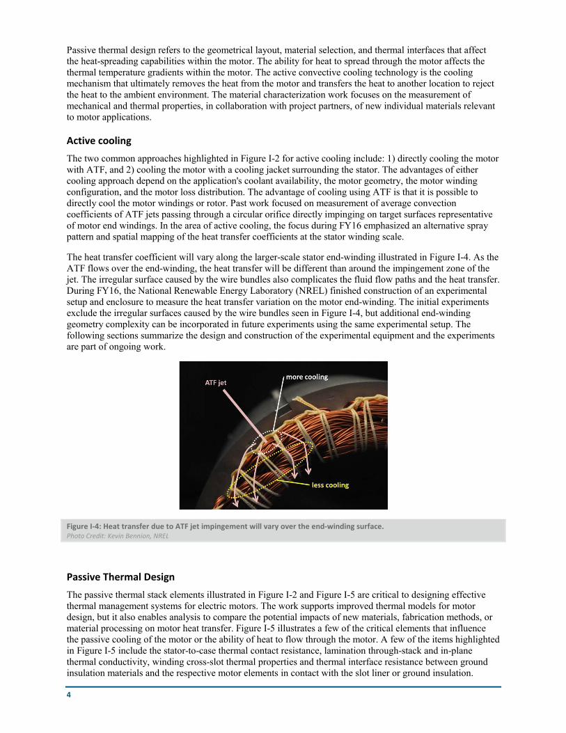
The heat transfer coefficient will vary along the larger-scale stator end-winding illustrated in Figure I-4. As the ATF flows over the end-winding, the heat transfer will be different than around the impingement zone of the jet. The irregular surface caused by the wire bundles also complicates the fluid flow paths and the heat transfer. During FY16, the National Renewable Energy Laboratory (NREL) finished construction of an experimental setup and enclosure to measure the heat transfer variation on the motor end-winding. The initial experiments exclude the irregular surfaces caused by the wire bundles seen in Figure I-4, but additional end-winding geometry complexity can be incorporated in future experiments using the same experimental setup. The following sections summarize the design and construction of the experimental equipment and the experiments are part of ongoing work.
Figure I-4: Heat transfer due to ATF jet impingement will vary over the end-winding surface. Photo Credit: Kevin Bennion, NREL
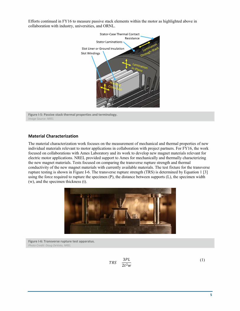
Passive Thermal Design The passive thermal stack elements illustrated in Figure I-2 and Figure I-5 are critical to designing effective thermal management systems for electric motors. The work supports improved thermal models for motor design, but it also enables analysis to compare the potential impacts of new materials, fabrication methods, or material processing on motor heat transfer. Figure I-5 illustrates a few of the critical elements that influence the passive cooling of the motor or the ability of heat to flow through the motor. A few of the items highlighted in Figure I-5 include the stator-to-case thermal contact resistance, lamination through-stack and in-plane thermal conductivity, winding cross-slot thermal properties and thermal interface resistance between ground insulation materials and the respective motor elements in contact with the slot liner or ground insulation.
5
Efforts continued in FY16 to measure passive stack elements within the motor as highlighted above in collaboration with industry, universities, and ORNL.
Figure I-5: Passive stack thermal properties and terminology. Image Source: NREL
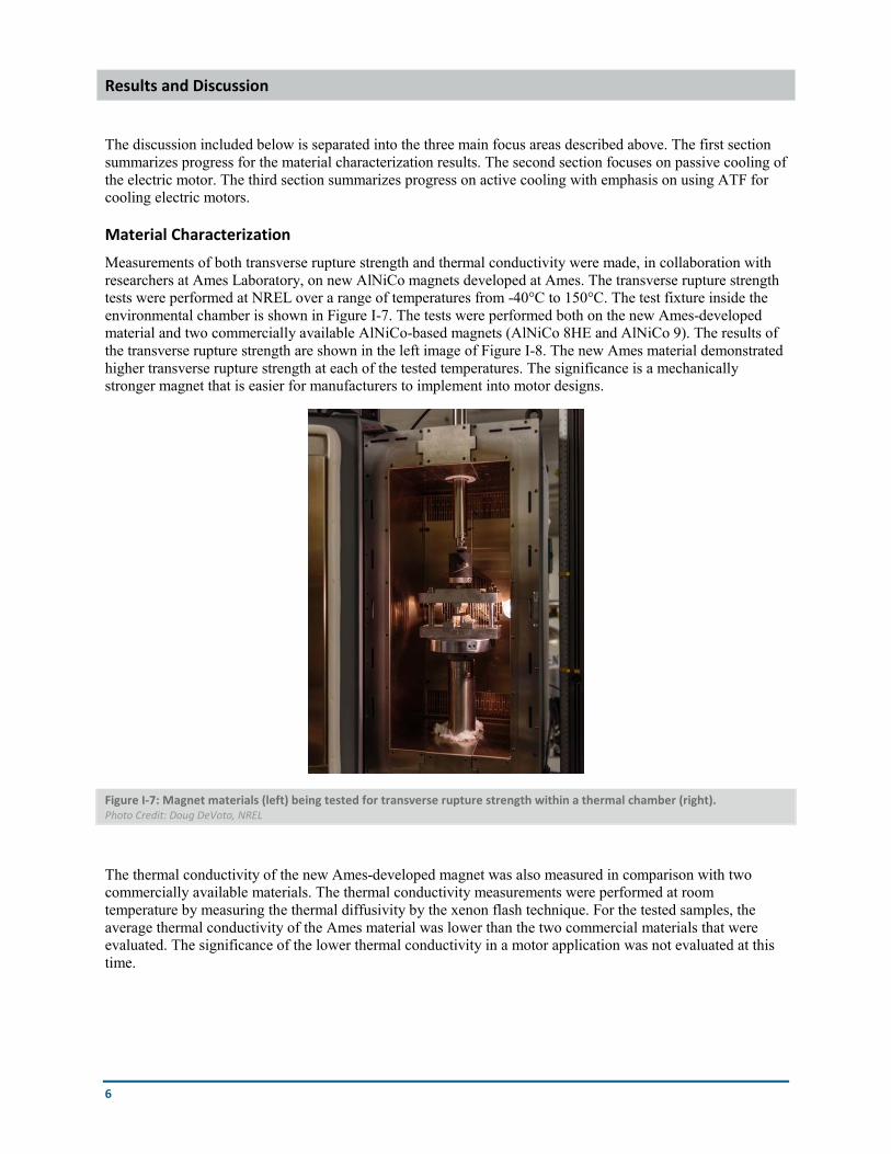
Material Characterization The material characterization work focuses on the measurement of mechanical and thermal properties of new individual materials relevant to motor applications in collaboration with project partners. For FY16, the work focused on collaborations with Ames Laboratory and its work to develop new magnet materials relevant for electric motor applications. NREL provided support to Ames for mechanically and thermally characterizing the new magnet materials. Tests focused on comparing the transverse rupture strength and thermal conductivity of the new magnet materials with currently available materials. The test fixture for the transverse rupture testing is shown in Figure I-6. The transverse rupture strength (TRS) is determined by Equation 1 [3] using the force required to rupture the specimen (P), the distance between supports (L), the specimen width (w), and the specimen thickness (t).
Figure I-6: Transverse rupture test apparatus. Photo Credit: Doug DeVoto, NREL
𝑇𝑇𝑇𝑇𝑇𝑇 =3𝑃𝑃𝑃𝑃
2𝑡𝑡2𝑤𝑤
(1)
6
Results and Discussion
The discussion included below is separated into the three main focus areas described above. The first section summarizes progress for the material characterization results. The second section focuses on passive cooling of the electric motor. The third section summarizes progress on active cooling with emphasis on using ATF for cooling electric motors.
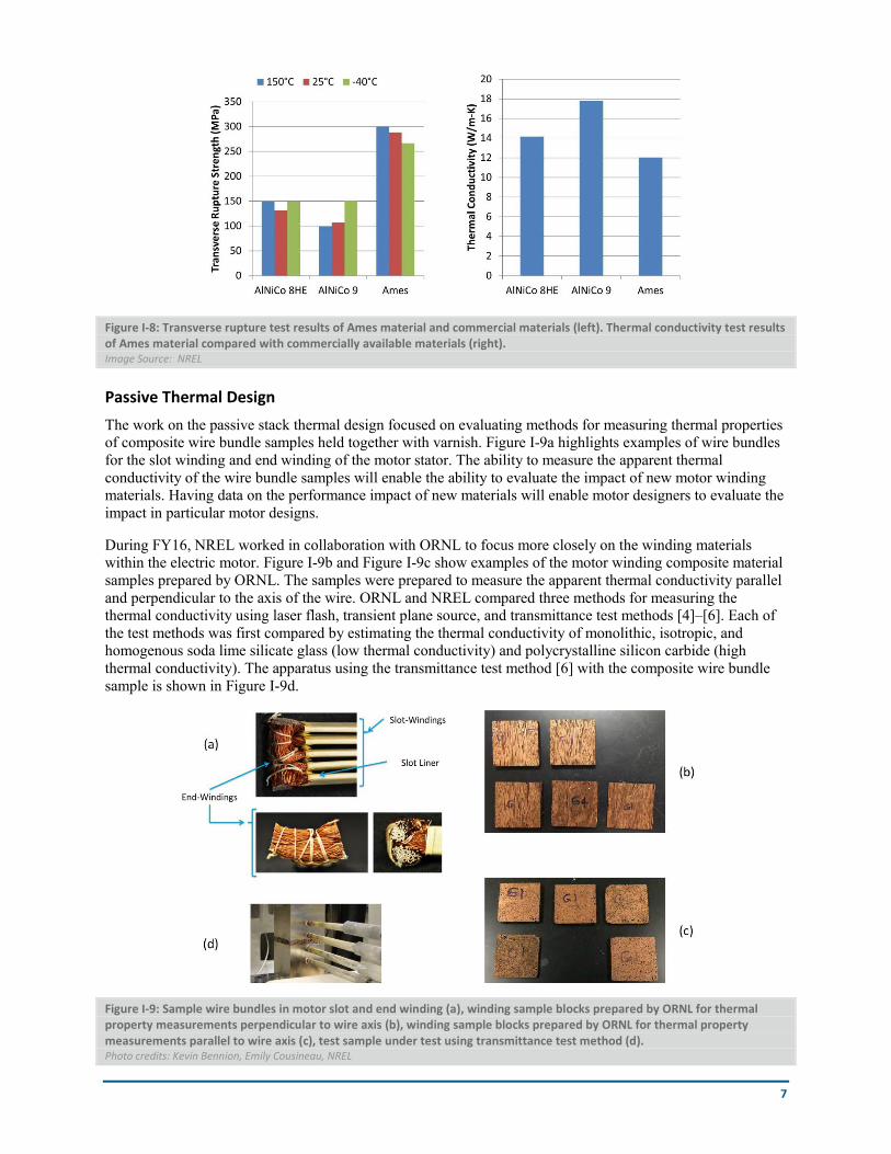
Material Characterization Measurements of both transverse rupture strength and thermal conductivity were made, in collaboration with researchers at Ames Laboratory, on new AlNiCo magnets developed at Ames. The transverse rupture strength tests were performed at NREL over a range of temperatures from -40°C to 150°C. The test fixture inside the environmental chamber is shown in Figure I-7. The tests were performed both on the new Ames-developed material and two commercially available AlNiCo-based magnets (AlNiCo 8HE and AlNiCo 9). The results of the transverse rupture strength are shown in the left image of Figure I-8. The new Ames material demonstrated higher transverse rupture strength at each of the tested temperatures. The significance is a mechanically stronger magnet that is easier for manufacturers to implement into motor designs.
Figure I-7: Magnet materials (left) being tested for transverse rupture strength within a thermal chamber (right). Photo Credit: Doug DeVoto, NREL
The thermal conductivity of the new Ames-developed magnet was also measured in comparison with two commercially available materials. The thermal conductivity measurements were performed at room temperature by measuring the thermal diffusivity by the xenon flash technique. For the tested samples, the average thermal conductivity of the Ames material was lower than the two commercial materials that were evaluated. The significance of the lower thermal conductivity in a motor application was not evaluated at this time.
7
Figure I-8: Transverse rupture test results of Ames material and commercial materials (left). Thermal conductivity test results of Ames material compared with commercially available materials (right). Image Source: NREL
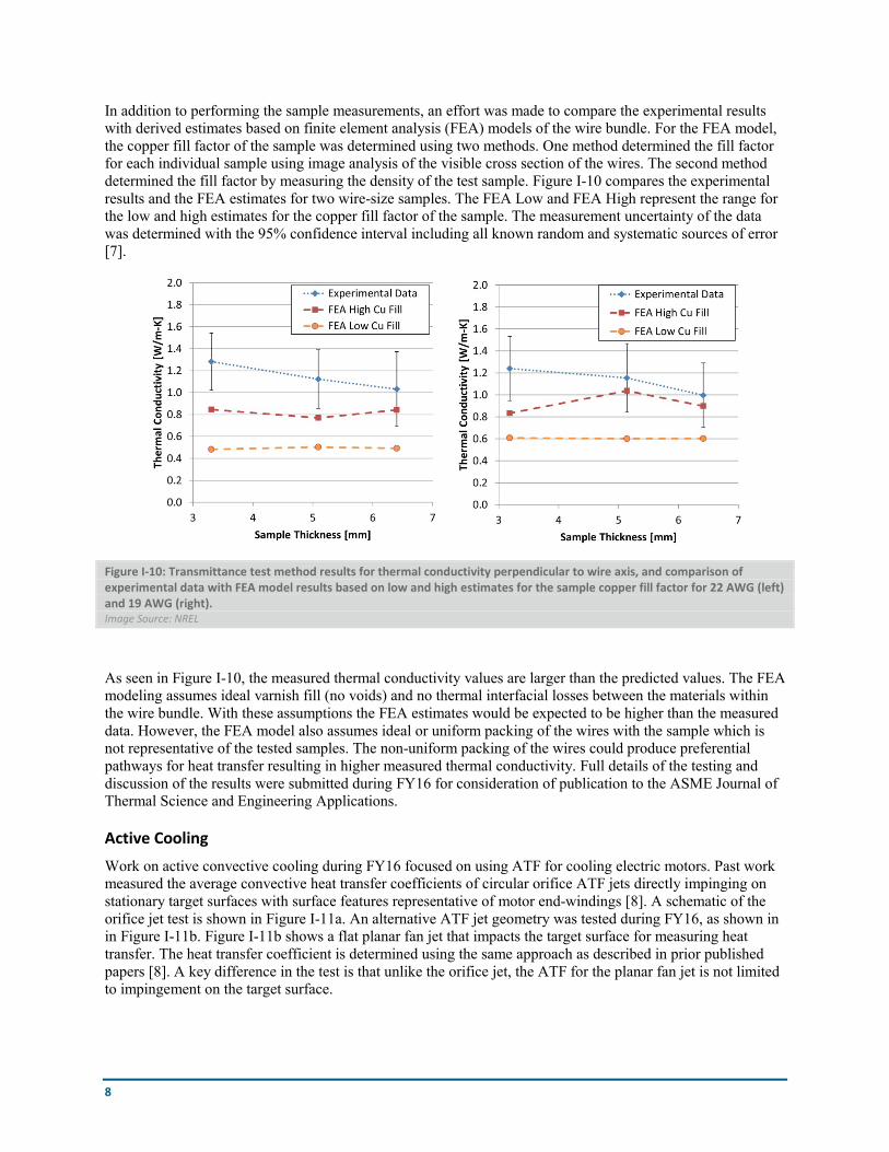
Passive Thermal Design The work on the passive stack thermal design focused on evaluating methods for measuring thermal properties of composite wire bundle samples held together with varnish. Figure I-9a highlights examples of wire bundles for the slot winding and end winding of the motor stator. The ability to measure the apparent thermal conductivity of the wire bundle samples will enable the ability to evaluate the impact of new motor winding materials. Having data on the performance impact of new materials will enable motor designers to evaluate the impact in particular motor designs.
During FY16, NREL worked in collaboration with ORNL to focus more closely on the winding materials within the electric motor. Figure I-9b and Figure I-9c show examples of the motor winding composite material samples prepared by ORNL. The samples were prepared to measure the apparent thermal conductivity parallel and perpendicular to the axis of the wire. ORNL and NREL compared three methods for measuring the thermal conductivity using laser flash, transient plane source, and transmittance test methods [4]–[6]. Each of the test methods was first compared by estimating the thermal conductivity of monolithic, isotropic, and homogenous soda lime silicate glass (low thermal conductivity) and polycrystalline silicon carbide (high thermal conductivity). The apparatus using the transmittance test method [6] with the composite wire bundle sample is shown in Figure I-9d.
Figure I-9: Sample wire bundles in motor slot and end winding (a), winding sample blocks prepared by ORNL for thermal property measurements perpendicular to wire axis (b), winding sample blocks prepared by ORNL for thermal property measurements parallel to wire axis (c), test sample under test using transmittance test method (d). Photo credits: Kevin Bennion, Emily Cousineau, NREL
8
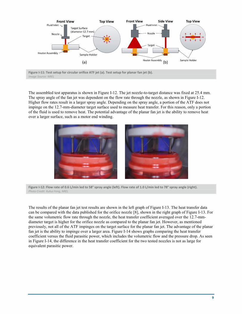
In addition to performing the sample measurements, an effort was made to compare the experimental results with derived estimates based on finite element analysis (FEA) models of the wire bundle. For the FEA model, the copper fill factor of the sample was determined using two methods. One method determined the fill factor for each individual sample using image analysis of the visible cross section of the wires. The second method determined the fill factor by measuring the density of the test sample. Figure I-10 compares the experimental results and the FEA estimates for two wire-size samples. The FEA Low and FEA High represent the range for the low and high estimates for the copper fill factor of the sample. The measurement uncertainty of the data was determined with the 95% confidence interval including all known random and systematic sources of error [7].
Figure I-10: Transmittance test method results for thermal conductivity perpendicular to wire axis, and comparison of experimental data with FEA model results based on low and high estimates for the sample copper fill factor for 22 AWG (left) and 19 AWG (right). Image Source: NREL
As seen in Figure I-10, the measured thermal conductivity values are larger than the predicted values. The FEA modeling assumes ideal varnish fill (no voids) and no thermal interfacial losses between the materials within the wire bundle. With these assumptions the FEA estimates would be expected to be higher than the measured data. However, the FEA model also assumes ideal or uniform packing of the wires with the sample which is not representative of the tested samples. The non-uniform packing of the wires could produce preferential pathways for heat transfer resulting in higher measured thermal conductivity. Full details of the testing and discussion of the results were submitted during FY16 for consideration of publication to the ASME Journal of Thermal Science and Engineering Applications.
Active Cooling Work on active convective cooling during FY16 focused on using ATF for cooling electric motors. Past work measured the average convective heat transfer coefficients of circular orifice ATF jets directly impinging on stationary target surfaces with surface features representative of motor end-windings [8]. A schematic of the orifice jet test is shown in Figure I-11a. An alternative ATF jet geometry was tested during FY16, as shown in in Figure I-11b. Figure I-11b shows a flat planar fan jet that impacts the target surface for measuring heat transfer. The heat transfer coefficient is determined using the same approach as described in prior published papers [8]. A key difference in the test is that unlike the orifice jet, the ATF for the planar fan jet is not limited to impingement on the target surface.
9
Figure I-11: Test setup for circular orifice ATF jet (a). Test setup for planar fan jet (b). Image Source: NREL
The assembled test apparatus is shown in Figure I-12. The jet nozzle-to-target distance was fixed at 25.4 mm. The spray angle of the fan jet was dependent on the flow rate through the nozzle, as shown in Figure I-12. Higher flow rates result in a larger spray angle. Depending on the spray angle, a portion of the ATF does not impinge on the 12.7-mm-diameter target surface used to measure heat transfer. For this reason, only a portion of the fluid is used to remove heat. The potential advantage of the planar fan jet is the ability to remove heat over a larger surface, such as a motor end winding.
Figure I-12: Flow rate of 0.6 L/min led to 58° spray angle (left). Flow rate of 1.0 L/min led to 78° spray angle (right). Photo Credit: Xuhui Feng, NREL
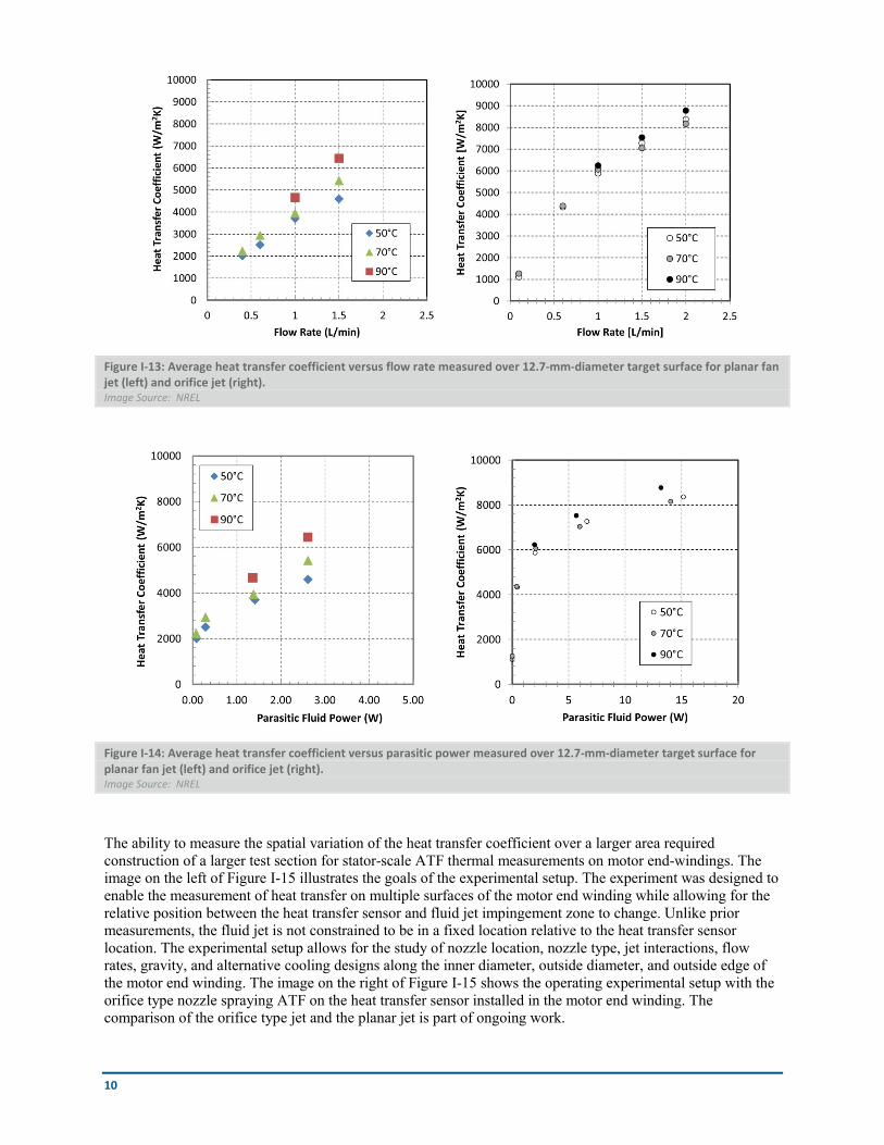
The results of the planar fan jet test results are shown in the left graph of Figure I-13. The heat transfer data can be compared with the data published for the orifice nozzle [8], shown in the right graph of Figure I-13. For the same volumetric flow rate through the nozzle, the heat transfer coefficient averaged over the 12.7-mm-diameter target is higher for the orifice nozzle as compared to the planar fan jet. However, as mentioned previously, not all of the ATF impinges on the target surface for the planar fan jet. The advantage of the planar fan jet is the ability to impinge over a larger area. Figure I-14 shows graphs comparing the heat transfer coefficient versus the fluid parasitic power, which includes the volumetric flow and the pressure drop. As seen in Figure I-14, the difference in the heat transfer coefficient for the two tested nozzles is not as large for equivalent parasitic power.
10
Figure I-13: Average heat transfer coefficient versus flow rate measured over 12.7-mm-diameter target surface for planar fan jet (left) and orifice jet (right). Image Source: NREL
Figure I-14: Average heat transfer coefficient versus parasitic power measured over 12.7-mm-diameter target surface for planar fan jet (left) and orifice jet (right). Image Source: NREL
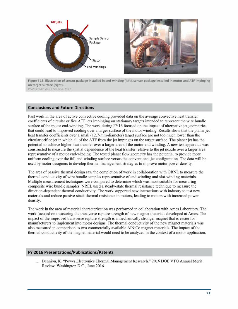
The ability to measure the spatial variation of the heat transfer coefficient over a larger area required construction of a larger test section for stator-scale ATF thermal measurements on motor end-windings. The image on the left of Figure I-15 illustrates the goals of the experimental setup. The experiment was designed to enable the measurement of heat transfer on multiple surfaces of the motor end winding while allowing for the relative position between the heat transfer sensor and fluid jet impingement zone to change. Unlike prior measurements, the fluid jet is not constrained to be in a fixed location relative to the heat transfer sensor location. The experimental setup allows for the study of nozzle location, nozzle type, jet interactions, flow rates, gravity, and alternative cooling designs along the inner diameter, outside diameter, and outside edge of the motor end winding. The image on the right of Figure I-15 shows the operating experimental setup with the orifice type nozzle spraying ATF on the heat transfer sensor installed in the motor end winding. The comparison of the orifice type jet and the planar jet is part of ongoing work.
11
Figure I-15: Illustration of sensor package installed in end-winding (left), sensor package installed in motor and ATF impinging on target surface (right). Photo Credit: Kevin Bennion, NREL
Conclusions and Future Directions
Past work in the area of active convective cooling provided data on the average convective heat transfer coefficients of circular orifice ATF jets impinging on stationary targets intended to represent the wire bundle surface of the motor end-winding. The work during FY16 focused on the impact of alternative jet geometries that could lead to improved cooling over a larger surface of the motor winding. Results show that the planar jet heat transfer coefficients over a small (12.7-mm-diameter) target surface are not too much lower than the circular orifice jet in which all of the ATF from the jet impinges on the target surface. The planar jet has the potential to achieve higher heat transfer over a larger area of the motor end winding. A new test apparatus was constructed to measure the spatial dependence of the heat transfer relative to the jet nozzle over a larger area representative of a motor end-winding. The tested planar flow geometry has the potential to provide more uniform cooling over the full end-winding surface versus the conventional jet configuration. The data will be used by motor designers to develop thermal management strategies to improve motor power density.
The area of passive thermal design saw the completion of work in collaboration with ORNL to measure the thermal conductivity of wire bundle samples representative of end-winding and slot-winding materials. Multiple measurement techniques were compared to determine which was most suitable for measuring composite wire bundle samples. NREL used a steady-state thermal resistance technique to measure the direction-dependent thermal conductivity. The work supported new interactions with industry to test new materials and reduce passive-stack thermal resistance in motors, leading to motors with increased power density.
The work in the area of material characterization was performed in collaboration with Ames Laboratory. The work focused on measuring the transverse rupture strength of new magnet materials developed at Ames. The impact of the improved transverse rupture strength is a mechanically stronger magnet that is easier for manufacturers to implement into motor designs. The thermal conductivity of the new magnet materials was also measured in comparison to two commercially available AlNiCo magnet materials. The impact of the thermal conductivity of the magnet material would need to be analyzed in the context of a motor application.
FY 2016 Presentations/Publications/Patents
1. Bennion, K. “Power Electronics Thermal Management Research.” 2016 DOE VTO Annual Merit Review, Washington D.C., June 2016.
12
Acknowledgments
The author would like to acknowledge the support provided by Susan Rogers, Technology Development Manager for the Electric Drive Technologies Program, Vehicle Technologies Office, U.S. Department of Energy Office of Energy Efficiency and Renewable Energy.
The significant contributions from Emily Cousineau, Xuhui Feng, Gilbert Moreno, and Doug DeVoto (NREL) to the project are acknowledged. The support, collaboration, and sample motor materials provided by Andrew Wereszczak and Tim Burress (ORNL) are acknowledged as well. The support and collaboration with Emma White, Liangfa Hu, and Iver Anderson of Ames Laboratory are also acknowledged.
References
[1] T. A. Lipo, Introduction to AC Machine Design, 3rd ed. Wisconsin Power Electronics Research Center, University of Wisconsin, 2007. [2] J. R. Hendershot and T. J. E. Miller, Design of Brushless Permanent-Magnet Motors. Oxford, UK: Magna Physics Publishing, 1994. [3] “Standard Test Method for Transverse Rupture Strength of Powder Metallurgy (PM) Specimens.” ASTM B524-12, ASTM International, West Conshohocken, PA. [4] “Standard Test Method for Thermal Diffusivity by the Flash Method.” ASTM E1461, ASTM International, West Conshohocken, PA, 2013. [5] “Transient Plane Heat Source (Hot Disc) Method.” ISO 22007-2, International Organization for Standardization, Geneva, Switzerland, 2008. [6] “Standard Test Method for Thermal Transmission Properties of Thin Thermally Conductive Solid Electrical Insulation Materials.” ASTM D5470, ASTM International, West Conshohocken, PA, 2012. [7] R. H. Dieck, Measurement Uncertainty: Methods and Applications. ISA, 2007. [8] K. Bennion and G. Moreno, “Convective Heat Transfer Coefficients of Automatic Transmission Fluid Jets with Implications for Electric Machine Thermal Management,” in ASME 2015 International Technical Conference and Exhibition on Packaging and Integration of Electronic and Photonic Microsystems and ASME 2015 12th International Conference on Nanochannels, Microchannels, and Minichannels, San Francisco, CA, United States, 2015.


![Applied Thermal Engineering - DiscreteHeat · 2018. 2. 28. · Applied Thermal Engineering 62 (2014) 382e389. converting from electric to alternative heating systems [3].Asa result](https://img.pdfslide.net/doc/110x75/60bf03726fceba0be61d4dd1/applied-thermal-engineering-discreteheat-2018-2-28-applied-thermal-engineering.jpg)