Embed Size (px)
Citation preview

Philips tech. Rev. 33, 215-234,1973, No. 8/9 215
Electric motors
E. M. H. Kamerbeek
Types of electric motor
The function of an electric motor is to convert elec-trical energy into mechanical work. The electrical ener-gy supplied is usually obtained from mechanical workapplied simultaneously somewhere else in a conversionin the other direction by means of generators. Electricmotors and generators are both referred to as electricalmachines and are essentially the same in construction;in principle the sarne electrical machine can performboth functions.
In this article a description will be given of the fun-damental principles of the operation of the electricalmachine. Various types of machine will be considered,all of them types that can be applied as small electricmotors. Here small motors are taken to be motors witha rating of I kilowatt or less.
Most electric motors carry out the energy conversionby way of a rotating movement - exceptions are thelinear electric motor, in which the movement is a linearone, and the vibrator rn The rotating part of themachine is called the rotor, and the stationary part thestator. At least one of these is provided with one ormore windings that are connected to the source ofelectric power. Depending on the type of source, themachine will be a d.c. motor or an a.c. motor.
In both cases the operation of the motor can oftenbe described by starting with the Lorentz force - theforce experienced by a conductor carrying a current ina magnetic field (see jig. J). If we imagine that themagnetic field in a d.c. motor is stationary, then toensure that the Lorentz force on a cond uctor at thecircumference of the rotor has the correct directionduring the whole of each revolution, the current mustbe regularly reversed. This is the function of the com-mutator, an essential feature of every d.c. motor [21.
The commutator is usually a mechanical device andgenerally consists of a cylinder formed by insulatedconducting segments mounted on the shaft; the wind-ings are connected to the segments and the current isfed to the segments by brushes (jig. 2).
A commutator of this type is subject to wear, par-ticularly when there is sparking between brushes andsegments. The sparking also causes radio-frequencyinterference. For these reasons there has been consider-
Dr Ir E. M. H. Kamerbeek is with Philips Research Laboratories,Eindhoven.
able interest recently in developing electronic methodsof commutation; motors with an 'electronic commuta-tor' are also called brushless d.c. motors.
The d.c. motor is the obvious choice when batterysu pplies have to be used. A characteristic feature of thed.c. motor is that its speed of rotation can be variedover a wide range. When this is a requirement, d.c.motors are sometimes used even though power has tobe taken from a.c. mains [31. The current then has to berectified; modern circuits for rectification and controlinclude semiconductor diodes, transistors and thyris-tors.
Fig. 1. The Lorentz force. A conductor carrying a current i ina magnetic field of flux density B is subject to a force F, theLorentz force. In the diagram the conductor is assumed to bestraight. F is at right angles to the plane of the vectors i and B;the magnitude F of the force is proportional to the sine of theangle a between i and B, the length I of the conductor, thestrength of the current and the magnetic flux density. In vectornotation F = li x.B. In motors i and B are usually perpendicularso that the magnitude of the force is given by F = liB.
Fig. 2. Commutator. Each segment is connected to a part of therotor winding. The current is supplied via two stationary brushes,which make a sliding contact with the segments.
[1] J. Timmerman, Two electromagnetic vibrators; this issue,p.249.
[2] An exception is the unipolar machine, but this is rarely used.A special form of this machine, which made use of supercon-ductivity, has been described by J. Volger in: A dynamo forgenerating a persistent current in a superconducting circuit,Philips tech. Rev. 25, 16-19, 1963/64.
[3] See the article by R. Raes and J. Schellekens about a d.c.motor with speed control for a washing machine, to appearin the second issue on electric motors.

216 Eo M. H. KAMERBEEK Philips tech. Rev: 33, No. 8/9
In a.c. machines there is no need for a commutator;use can be made here of the periodic change in>thedirection of the current in the a.c. mains. This meansthat a relation must exist between the frequency of thea.c. current and the speed of revolution of the machine.In synchronous machines the number of revolutions persecond is proportional to the frequency of the current.Synchronous machines are therefore widely appliedwhere constant speed is a first requirement. Then thereis the group of asynchronous motors; these motors runat a speed a little lower than the 'synchronous' value,and the difference (the slip speed) increases with the
load on the motor. Because of this difference in speedcurrents areinduced in closed circuits in the rotor; thisinduction is essential to the operation of this type,which is therefore usually referred to as the inductionmotor. The induction motor is the most common typeof a.c. motor.In some applications the relation between the speed
and the mains frequency is a nuisance. One way aroundthe difficulty is to use a commutator, even though thesupply is a.c. This is because a commutator motor inthe correct kind of circuit can operate from a mainssupply of any frequency - and not just if that fre-
Table J. Survey of the most important types of motor. The torque-speed characteristics show thevariation of the electromagnetic torque Te as a function of the rotational speed 11 of the motor.
I TypeI
Torque-speed characteristic I Special features See page
~----"'I ~ ti IAlso applied as 217stepping motor and
Motor withbrushless d.c. motor
permanent-magnet rotor _n
~~ @I I
Also applied asSynchronous motors . stepping motor and 223
brushless d.c. motorReluctance motor o:
I~----"'I I Self-starting 224Hysteresis motor
~----"'I~ P<\ An external resistance Rext0
in the rotor circuit can beMotor with '" used for startingslip-ring rotor Rext
Asynchronous or ~~ @~
Torque-speed characteristic 226induction motors
0 affected by shape of cage(double cage, skin-effect cage)
Squirrel-cage motor
~----"'I CO~
Skin effect in the rotoris of major importance
Motor withsolid rotor
=----"'1 QI \ Permanent magnet
often used in small motorsSeparately instead of field windingexcited motor
Commutator motors Ll Q =
I \ 230Shunt motor
I~~-l~ I ~Can also be used for a.c.(universal motor)
Series motor

Philips tech. Rev. 33, No. 8/9 ELECTRIC MOTORS 217
,quency is zero, as for a d.c. motor. In practice a motorto be used in this way has to be specially designed, andis called a universal motor. If such a motor is run froman a.c. supply the currents in the rotor and stator wind-ings continually change sign simultaneously. Thismeans that the interactive force, which is proportionalto the product of the two currents, maintains the samesign.
The speed of a synchronous or asynchronous motor can alsobe varied over a wide range if it is supplied from a source ofvariable frequency. This requires the mains frequency to be con-verted to another frequency; there are rotary frequency conver-ters (a motor driving a generator) and static (or electronic)frequency converters. In fact the operation of the commutatorin a d.c. or universal motor can also be considered as a frequencyconversion. This is why the combination of a synchronous motorand a frequency converter is found to behave in a similar way toa d.c. commutator motor under certain conditions.
Finally, there is the stepping motor [*l. This isessentially a motor of the synchronous type, suppliedby electronically generated pulses of current. Eachpulse produces a constant angular rotation. The num-ber of angular rotations (the 'steps') is equal to thenumber of pulses applied, so that a digital signal isconverted into a mechanical displacement. Steppingmotors are used in applications such as numericallycontrolled machine tools.Motors of the various basic types listed here, except
perhaps the stepping motor, were in existence long be-
fore the end of the nineteenth century [**l. Neverthe-less, new developments are still under way. The maintrends are:- Improvement of the various characteristic features
(the efficiency, the variation of torque with speed,the starting characteristic, etc.).
- Increasing the power/weight and power/volumeratios.
- Improving reliability and safety.- Improving methods of motor control.These developments are possible since improvedmagnetic and insulating materials are now available,computers can be used in design work, and new pro-duction techniques can be used, such as sintering ofrotors. The availability of electronic components, inparticular thyristors and transistors, has also increasedthe range of possibilities, especially in motor control.We shall now examine the operation and character-
istics of the most important types of motor in more de-tail, and derive an expression for the delivered torque.Table I shows a diagrammatic survey of the motortypes examined in this article, with the page references.Types with an external rotor, sometimes used in smallmotors, are not described separately as they do notdiffer in principle from the types with an internal rotor.Since the synchronous motors to be discussed in thisarticle are of simple configuration, we shall start withthese. Asynchronous or induction motors and thecommutator motors will then follow.
I. Synchronous motors
The kinds of synchronous motor to be discussed hereall have a rotor with no windings. This rotor can be apermanent magnet, in which case its magnetization willgive it a preferential position with respect to themagnetic field produced by the stator windings. Inanother type, the reluctance motor, the rotor is notpermanently magnetized, but is made from a materialof high permeability; this rotor is not cylindrical andtherefore has a preferential position for which themagnetic resistance - the reluctance - ofthe magneticfield is at a minimum. In both motors the stator wind-ings excite a rotating magnetic field; the rotor tries tomaintain the preferential position with respect to thefield and rotates with it, provided that it is not pre-vented from doing so by too great a load on the shaft.In the third type of motor to be discussed, the hysteresismotor, there is also a rotating stator field. This inducesa magnetization in the rotor, as in the reluctance motor.The rotor is now cylindrical, however, and made of amaterial that has considerable magnetic hysteresis. Be-
cause of this hysteresis the magnetization always lagsbehind the direction of the rotating stator field, thusgiving a torque.
Synchronous motor with permanent-magnet rotor andcylindrical stator bore
Let us now pass on to a calculation of the torqueoperating on the rotor of a synchronous motor with apermanent-magnet rotor. We shall assume here thatthe motor is constructed as in the cross-sectional dia-gram of fig. 3. A cylindrical rotor can rotate in thecylindrical bore of the stator. The stator - usuallylaminated in practice to reduce eddy currents, i.e. madefrom a stack of thin stampings insulated from eachother - carries two 'diametral' windings 1, l' and 2,2'.In fig. 3 these are shown in the air gap, but in practice[*1 We intend to publish a separate article on this subject in the
third issue on electric motors. (Ed.)[**1 We intend to include an article on the history of hte electric
motor in the third issue on electric motors. (Ed.)

218 E. M. H. KAMERBEEK Philips tech. Rev. 33, No. 8/9
they can be mounted in slots in the stator. The rotor ishomogeneously magnetized parallel to a diameter.It is not difficult to calculate the forces experienced by
the sides of the coils in the magnetic field of the rotorwhen a current flows. These forces taken together give atorque on each coil. The reaction torque on the rotoris then equal in magnitude to the sum of the torqueson the two coils but of opposite sense. The only com-ponent of the magnetic field that contributes to thetorque is the radial component that crosses the air gap.This component is therefore the only one consideredin the rest of the discussion. Similarly, the forces ex-perienced by the coils from their own and one another'sfield will not be taken into account, since they do notcontribute to the torque.
Fig. 3. Schematic cross-section of a synchronous motor with acylindrical permanent-magnet rotor (N north pole, S south pole).The rotor rotates inside the cylindrical bore of a stator carryingtwo 'diarnetral' coils 1,1' and 2,2' When current flows in thecoils in the magnetic field of the rotor they experience a torque;a reaction torque Te of the sarne magnitude but opposite signthen operates on the rotor. If suitable a.c. currents flow in thecoils and the rotor has the correct angular velocity, the torqueon the rotor then always has the same sign and the rotation ismaintained. The position of the rotor is given by the angle e;a rotation in the direction of increasing e is taken as positive.The angle cp is the coordinate used in the calculation for positionon the stator circumference.
If a current IS(1) flows in the coil I, then a side ofthis coilof length l (at right angles to the plane of thedrawing in fig. 3) will experience a Lorentz forceF = Js(l)NslB, where B is the magnetic flux densityin the air gap and N; is the number of turns in the coil.Using B everywhere for the radial component, as indi-cated above, then whatever the position of the rotor Fis always perpendicular to the plane of the coil. Themagnitude of B varies sinusoidally along the circum-ference of the rotor: B = Ê cos ,pr, where ,pr is theangle in radians with respect to the plane of symmetryof the rotor. For an arbitrary angle e of the rotor withrespect to the stator the variation of B around the stator
is given by B = Ê cos (,ps - e); here ,ps is the coor-dinate along the circumference of the stator (see fig. 3).The force on the side of the winding at <Ps= nl2 isthen F = IS(1)NslÊ sin e; the force on the other side(at <Ps= -nI2) is equal in magnitude but of oppositesense. The torque resulting from the two forces is 2aF,where 2a is the width across the coil. If the second wind-ing shown in fig. 3 is not taken into account this is theelectromagnetic torque acting in the motor. With thedirections of current and magnetization of the rotor asshown in fig. 3 the sense of the reaction torque on therotor is opposite to the direction of increasing e, i.e.it is negative, so that for this torque we have:
Te(l) = -2alls(1)NsÊ sin IJ. (1)
The torque is zero in the two positions opposite eachother for which e is equal to zero or n radians. In thefirst position the equilibrium is stable; for a small de-viation of the rotor it experiences a torque tending toreturn it to this position. This is the preferential posi-tion referred to above. In the second position the eq ui-librium is unstable; the sense of the torque is such thata small deviation will increase.
By making use of the coil 2, which is rotated by nl2radians with respect to the first coil, the rotor can begiven another stable final position nl2 radians aheadof or behind the first one. In this way the rotor can bekept rotating in 'steps'. This is the essential principleof a stepping motor with a permanent-magnet rotorand a 'stepping angle' of nl2 radians.
However, what is usually required is a steady con-tinuous rotation of the rotor. This can be obtained bysupplying the coils / and 2 with sinusoidally varyinga.c. currents of eq ual magnitude and differing in phaseby nl2 radians. To calculate the torque in this case theexpressions for the two currents, iS(1) = Îs cos wt andiS(2) = Îs sin cot (where w is the angular frequency ofthe a.c. currents and t the time) can be substituted inequation (1). Summing the torques produced by thetwo coils will give the total torque Te. If it is now furtherassumed that the rotor rotates at a constant angularvelocity Wr, so that e = Wrt + eo, then for the totaltorque we have:
Te = -2alÎsNsB sin{(wr - w)t + eo}. (2)
The time-average value of this torque can only differfrom zero if Wr is equal to t», i.e. if the rotor runs atsynchronous speed. This means that the motor will notoperate as a motor at any speed other than the syn-chronous speed. It also means that the motor will notstart of its own accord, since the time average of thetorque at zero speed is also zero. This is an importantpractical difficulty; to avoid it synchronous motors areoften provided with a second rotor of another type on

Philips tech. Rev. 33, No. 8/9 ELECTRIC MOTORS 219
the same shaft and rotating in the same stator. Thesecond rotor can be for example a squirrel-cage rotor,as used in induction motors (see below).
At the synchronous speed the torque is constant:
Te = -2alisNsÊ sin Bo.
With the motor rotating at constant speed, theaccelerating torque acting on the rotor is apparentlyzero. This means that the magnitude of the electro-magnetic torque is exactly large enough to compensatethe torques produced by the load and by friction. At agiven current the only variable in (3) that could enablethe motor to match the electromagnetic torque to theload is the angle eo between the rotor and the statorfield. For motor operation eo is negative; the rotor lagsbehind the rotating stator field, falling further back asthe load increases. When eo is equal to -n/2 the electro-magnetic torque has reached its maximum; if the loadincreases further the motor will be unable to maintainits constant speed of rotation; it will 'fall out of step',and come to rest. This shows the limited flexibility ofthe synchronous motor, which cannot maintain theequilibrium between the electromagnetic and mechan-ical torque by a reduction in speed.
The synchronous motor will operate as a generatorwhen the rotor is externally driven. The effect of theelectromagnetic forces on the rotor is then to prod ucea braking torq ue, of the opposite sense to that in motoroperation. In this arrangement eo in equation (3) isnow positive.
Higher harmonics
So far it has been assumed that the magnetic fieldoriginating from the rotor is sinusoidally distributedalong its circumference. This is usually only approxi-mately true. Terms of higher order are therefore pres-ent; these give rise to fluctuations in the torque atevery revolution of the rotor, which interfere with theeven running of the motor.
These fluctuations can be counteracted by using dis-tributed windings 1 and 2 instead of the diametral coils1 and 2. A distributed winding consists of a number ofcoils at various points of the stator circumference, allconnected in series. In this case it is more convenientto replace the quantity Nsis(l) by the current-densitydistribution SS(l)( <Ps), expressed in amperes per unit oflength along the stator circumference. Since all theturns are in series, SS(l) is equal to iS(l)Zs(<Ps), where Zs
is the number of turns per unit of length. This quantityZs is called the copper-density distribution. The sign ofthis function indicates whether the current at the loca-tion <Ps flows in the positive or negative direction(@ or 0 in fig. 3) when a positive current is appliedat the terminals.
(3)
In many cases a distributed winding in which SS(l)
is distributed sinusoidally around the stator circum-ference is ideal. As we saw above, a uniform torquecan be obtained with a purely sinusoidal distribution ofthe rotor flux density and a non-sin usoidal current-density distribution. An even torque is also obtainedwith a sinusoidal current-density distribution and amagnetic flux density that is not sinusoidally distrib-uted, since the current i and the magnetic flux den-sity B are equivalent factors in the expression F = liBfor the Lorentz force.
In practice only an approxirnation to a sinusoidalcurrent-density distribution is attempted. The coils ofthe winding are usually arranged in equidistant slotsin the stator circurnference. Fig. 4 shows a stator with
Fig. 4. Schematic cross-section of a synchronous motor in whichthe two windings 1,1' and 2,2' each consist of three coils. Thestator has twelve equidistant slots for the coils. This arrangementis used to give an approximation to a sinusoidal current-densitydistribution.
twelve slots, in which there are two windings, each con-sisting of three coils. Usually two to five coils per wind-ing are considered sufficient, with equal numbers ofturns in each coil. This approach gives a considerablereduction in the torque fluctuation.
If the distribution of the rotor flux density Be around the statorcircurnference is symmetrical but not sinusoidal, it will containhigher harmonics and we can write:
Br(<ps) = Brl cos (<Ps - e) + Br2 cos 2 (<Ps - e) ++ Br3 cos 3 (<Ps - IJ) + ." .
At the synchronous angular velocity w the torque is then
Te = - 2aUsNs{ Bri. sin eo - Br3 sin (4wt + 3IJo) ++ Br5 sin (4wt + Seo) - ... }.
This shows that the torque will pulsate at angular frequenciesof 4w and higher. At the same time it can be seen that only theodd harmonics in the spatial distribution of B, will contributeto the pulsation of the torque.
If the winding is distributed, the calculation of the torque ismore complicated. Fig. 5 shows the variation around the circum-

220 E. M. H. KAMERBEEK Philips tech. Rev. 33, No. 8/9
copper-distribution function zs(<Ps). Such a machine iscalled a two-phase machine. A current-density wavecan also be excited by using three stator coils, separatedby angles of 2n/3 radians (seefig. 6), and supplied by
0ol------,r-r--r-r-....-;~-----L.--_-...L.Jcp-s...L..IL-L..L"-~27r a.c. currents similarly separated in phase by 2n/3radians: ÎS(l) = is cos cot, ÎS(2) = is cos (wt - 2n/3),iS(3) = is cos (wt - 4n/3). This is called a three-phasesystem. The fundamental of the current-density waveproduced in such a three-phase machine is given by--1(31.-
Fig. 5. The variation of the current-density distribution SS(l) ofstator winding 1 around the stator circumference of the motorshown in fig. 4. The other curve shows a possible curve for therotor flux density Be around the stator circumference. The angle IXcharacterizes this trapezoidal curve and the angle fl representsthe width of the slots.
ference of the stator of the current-density distribution SS(l),
applying to stator coil}, for the motor of fig. 4. The 'current-density pulses' have the width of the slot opening and are reck-oned as positive when the current flows 'into the paper' in fig. 4.The other curve shown in fig. 5 is an example of a possible non-sinusoidal flux-density distribution. A general method for thecalculation of the torque on stator coil} starts with the expres-sion, assuming certain symmetries, of both the rotor flux densityand the current-density distribution in terms of a series in <Ps.This has already been done above for the rotor flux density, andfor the current-density distribution we obtain:
SS(l) = ÎS(l)ZS<q,S) = -is(l)(Zsl sin ,ps + Zs3 sin 3,ps ++ zss sin 5,ps + ...).
The total torque, for which the general expression:z"
Tc = al J (SS(l) + SS(2»)Bra d,pso
is applicable, is then given by
Tc = -na2lts {zslBr1 sin 00 + zs3Br3 sin (300 + 4wt) ++ zssBr5 sin (500 + 4wt) + ... }.
For a purely sinusoidally distributed winding Zs3, Zs5 and higherterms are zero. This cannot be achieved for all the terms. How-ever, some degree of compensation for this can be obtained bychoosing a distribution for the rotor flux that will make theremaining troublesome terms in the series for Be very small.With the configuration shown in fig. 5, for IX = n/3 and fl = n/60radians:
IZS3
1 = 0.37Zsl
I!::I =0
Izssl = 0.27Zsl
I!::I = 0.04
IZS?I = 0.27Zsl
I!::I = 0.02
The amplitudes of the terms in 300, 500 and 700 are thus respec-tively 0%, 1% and 0.5% of the maximum value of the first term.
Three-phase and single-phase machines
The machine shown in fig. 4 has two windings thattogether set up a current-density wave whose funda-mental spatial harmonic is given by
Ss = i'szSl sin (wt - <ps).
Here Zsl is the amplitude of the fundamental of the
Ss = ~.i'szSl sin (wt - <ps).
The current-density wave around the stator circum-ference produces a magnetic field in the air gap. For a
Jt,/'
//II\\ /" /'-----
Fig. 6. Winding of a synchronous motor operating from a th ree-phase supply. The rotating stator field Bs is excited by the threestator coils carrying a.c. currents separated in phase by 2n/3radians.
purely sinusoidal current-density wave the magneticfield wave excited around the stator circumference (therotating field) is also sinusoidal, provided that the airgap is uniform or the rotor consists of a material whosepermeability is equal or nearly equal to that of air (e.g.permanently magnetized ferroxdure). The flux-densitywave Bs is then always displaced in phase by n/2 ra-dians with respect to the current-density wave Ss.A special case arises in a synchronous motor when
only one stator winding is energized, say winding 1.The conditions for a current-density wave of constantamplitude and angularvelocity are then no longer satis-fied. The fundamental of the current-density distribu-tion then has the form -ÎS(l)ZSl sin <ps and is zero for<Ps = 0 and CPs = st, This 'standing' wave can howeverbe resolved into two travelling waves rotating in op-posite directions:
-iS(l)ZSl sin <ps cos tot = t is(l)Zsl sin (wt - <Ps)++ t ÎS(l)ZSl sin (-wt - <Ps).

Philips tech. Rev. 33, No. 8/9 ELECTRIC MOTORS 221
The motor - it is called a single-phase motor - canthus rotate clockwise or anticlockwise at the synchro-nous speed. However, because of the current-densitywave in the opposite sense the torq ue is not constant,but pulsates at twice the mains frequency.
Multipele machines
In all the machines so far discussed the air-gap fieldhas a single pair of poles, and they are therefore knownas two-pole rotating-field machines; the angular veloc-ity of the rotating field is equal to the angular fre-quency w of the supply mains.
A stator can also be wound in such a way that theair-gap field has four poles; alternate north and southpoles are then obtained around the stator with n/2radians between poles. Fig. 7 shows how the statorwindings are arranged in the four-pole version of themotor of fig. 3. Winding 2 is now displaced by n/4radians with respect to winding 1, which means thatthe angular velocity of the rotating field, and thereforethe synchronous angular velocity of the motor, is equalto half the angular frequency of the mains. The rotoris magnetized in such a way that it also has four poles.
This provides a way of reducing the speed of a syn-chronous motor by a factor of two. The procedure canbe extended to give six-pole and eight-pole motors, orin general terms 2p-pole motors, where p is the numberof pairs of poles.
Supply from a constant-voltage source
In all the calculations given above for the torque thesituation has been simplified by the assurnption that themagnitude of the stator currents is given. In practicethis is rarely the case. The motor is almost always con-nected to a source of supply whose voltage at the ter-minals is given; the magnitude of the currents thenvaries with the load on the motor.
To derive an expression for the torque in terms ofthe terminal voltage instead of the stator currents wemust calculate the currents that flow for a given voltageat the terminals. The voltage induced in the statorwinding by the alternating magnetic fields is an impor-tant quantity in these calculations. Part of this voltagewill be related to the magnetic field produced by thestator winding itself and will depend upon the induct-ance L« of the winding; there is also a magnetic fieldproduced by the rotor that will induce a voltage in thestator winding when the rotor is rotating. A usefulrepresentation is given by the equivalent circuit shownin fig. 8 for a stator winding. This equivalent circuitcorresponds to the equation in complex notation:
V.s = (Rs + jwLs)/s + Esr.
Here Vs, Is and Esr are complex numbers whose moduli
are equal to the r.m.s. values of the terminal voltage,the current and the motional e.m.f. or 'speed voltage'induced by the rotor field respectively, and with argu-ments equal to the appropriate phase angles. R; is theresistance of the stator winding, and as previously wis the angular frequency of the mains supply.
Equation (4) gives the desired relation between ap-plied voltage and current; if we introduce the param-eter ), = I Esr/ Vs I then Is can be expressed in explicitterms:
Is = - ~ II- Àej(lJo + n12) J. (5)n, + JwLs
The parameter À has a constant value for a synchro-nously operating motor; for a terminal voltage of givenamplitude and frequency À depends only on the con-struction of the motor. When the rotor is stationary À
in equation (5) is equal to zero; the stator current thentakes the value corresponding to the impedanceRs + jwLs of the stator winding. The angle (Jo + n/2is the phase angle of the voltage induced by the rotorfield with respect to the applied voltage; (Jo is the rotorposition at the instant when the voltage across thewinding reaches its maximum value. As we saw earl ier,(Jo varies with the load on the motor; equation (5) showshow h then varies.
1---: ;Ps2 ...
Fig. 7. Stator windings and magnetization of the rotor in a four-pole synchronous motor. The two halves of the stator winding 1and 2 carry the same current. T n each cycle of the a.c. supplythe motor makes half a revolution.
(4)Fig. 8. Equivalent circuit of a synchronous motor with statorresistance R« and stator inductance L«. Vs supply voltage. Is cur-rent in the stator winding. The e.m.f. Es!" induced by the field ofthe rotating rotor is represented by a constant-voltage a.c. source.

222 E. M. H. KAMERBEEK Philips tech. Rev. 33, No. 8/9
The equations (4) and (5) apply to each stator wind-ing separately. The calculation of the torque, forexample for the motor shown in fig. 3 with two wind-ings, is most readily performed by setting up a powerbalance. The mechanical power Tew can then be setequal to the electrical power taken up by the two statorwindings, less the ohmic losses in the windings.
The power balance can be expressed in complex notation by:
Tew = 2 Re(/5(1)* V.(l) - 1.(1)*IS(l)Rs) = 2 Re(/s(l)* £5r(1)). (6)
Here the asterisk indicates the complex conjugate. The powerbalance is the same for both stator windings; it is therefore suf-ficient to take the electrical power for a single stator windingand double it.
With the aid of the two equations (4) and (5) the current IS(l)and the speed voltage £5r(1) can be expressed in terms of theterminal voltage Vs in (6). Returning now to real quantities andwriting Vs for the r.m.s. value of the terminal voltage, then fromthe power balance:
2 ÄVs2Tc = - V {cos (00 + n/2 + xs)- Äcos xs} •W R52 + w2L52
Here xs = arctan wLs1R5' the phase angle of the stator impe-dance.
If Rs is much smaller than wLs the stator resistancecan be neglected in the expression for the torque. Aconvenient expression for the torque at a given r.m.s.value Vs of the terminal voltage can then be obtainedfrom the power balance:
2ÀVs2Te = - -- cos 00•
w2Ls
For motor operation Te is positive and therefore
3n n- -< 00<--'2 2'for stable operation however 00 must not be smallerthan -n, since as soon as the motor falls behind bymore than n radians the torque decreases and the motorfalls out of step. Note that the angle 00 is the 'phaseangle' of the rotor with respect to the a.c. voltageacross winding 1, whereas in (3) 00 is a phase anglewith respect to the current in winding 1.
Synchronous motors with non-uniform air gap
There are also synchronous motors that do not havea cylindrical stator bore but have salient poles (fig. 9a).In these motors the rotor can be subject to a torqueeven when there is no current in the stator winding.This is because it tries to take up a position in whichthe reluctance (the 'magnetic resistance') to the flux ofthe permanent magnet is at a minimum. The torqueinvolved here is a stator-reluctance torque. In a motorlike the one in fig. 9a this makes no contribution to the
(7)
energy conversion, since on rotation its average valueis equal to zero.If the rotor is non-cylindrical (fig. 9b) instead of the
stator and also has a magnetic permeability greaterthan that of air, then a rotor-reluctance torque can beproduced under the influence of the stator field. Theoperation of the reluctance motor is based upon thistorque.In the treatment of both types of motor it is probably
best to start from energy considerations, since we canthen obtain some insight into their characteristicswithout previous knowledge of the complicated varia-tion of the magnetic field. Also, a direct calculation ofthe electromagnetic forces acting on the stator in thecase of fig. 9a would not only have to include theLorentz force on the conductors ofthe stator winding:it would also have to include the forces operating onthe stator core. Such a calculation would be a com-plicated exercise. To make the energy considerationsas general as possible it will be assumed that we havea kind of motor that combines the characteristic feat-ures of both types; with stator and rotor both non-cylindrical, and with a permanent-magnet rotor thatnevertheless has a higher permeability than that ofair (fig. 9c). In this motor we are concerned with energyin various forms: the applied electrical energy, whichin a short time ó't is equal to vsisf1l, the energy dissi-pated in the resistance of the stator winding, equal toRsis2ó't, the magnetic-field energy present in the motorWm, and the mechanical energy Teó'O supplied by theshaft to the load during a rotation ó,0. The appliedenergy is equal to the sum ofthe dissipated and suppliedenergy and the change in the magnetie-field energy; indifferential form:
Here Wm is a function of the stator current is and theangular position 0 of the rotor.To derive the torque from this energy balance we
make use of an expression for the voltage Vs across thestator winding:
d!PsVs = Rsis +-.
dt
where !Ps is the total magnetic flux linked with thestator winding. To a first approximation this linkedflux can be equated to the product ofthe total magneticflux through a stator pole and the total number ofturns. !Ps is also a function of both isand O.Substituting in the energy balance it follows that
à !Ps àWmTe = is--- --.M 00
(8)
Both terms on the right-hand side are connected with

Philips tech. Rev. 33, No. 8/9 ELECTRIC MOTORS 223
Fig. 9. a) Synchronous motor with anon-uniform air gap and salient po-les. The permanent-magnet rotor hasa preferential position, even whenthe stator winding is not energized.b) Non-cylindrical rotor in a cylin-drical stator. If the permeability ofthe rotor is greater than that of air,it takes up a preferential positionparallel to the existing stator field.c) A scheme for a motor combiningthe characteristics of (a) and (b).
g
the magnetic field. To be able to draw the correct con-clusions for the various types of motor from this equa-tion, we must separate the flux CPs linked with thestator winding and also the magnetie-field energy Wm
into a contribution from the stator current, character-ized by the inductance Ls, and a contribution from therotor. Both components vary with the angular posi-tion IJ of the rotor. We then have:
CPs = Ls( IJ) is + CPsr( IJ),Wm = -tLs(lJ)is2 + Wmr(IJ).
Substituting this in (8) gives the general expression forthe torque
d CPsr( IJ)Te = is
dIJdWmr(lJ) l_ i 2 dLs(lJ) 9
dIJ + 2 s dIJ . ()
The first term is equal to the calculated torque in equa-tion (6) for the motor with cylindrical stator and rotor.However, in the general case there are extra terms; thesecond term is related to the stator reluctance, the thirdto the rotor reluctance.
Single-phase synchronous motor with non-cylindricalstator
We now confine ourselves to the case shown infig. 9a, of a motor with a cylindrical rotor magnetizedalong a diameter and a non-cylindrical stator. This is asingle-phase synchronous motor, and therefore givesthe pulsating torque peculiar to this type. This is nogreat handicap in applications such as small domesticequipment, for which such motors are ideally suitedbecause of their simple construction. In the designhowever full account must be taken of the notableinstabilities that can appear in this motor [4].
Since the motor has a cylindrical rotor the induct-ance L; of the stator winding is not dependent on theangular position IJ of the rotor, and the last term inexpression (9) for the torque therefore disappears. Itcan be shown that the quantities appearing in the othertwo terms depend on IJ as follows:
CPsr(lJ) = »; cos (IJ + a),Wmr(lJ) = Wl - W2 cos 2(1J+ (3), Wl > W2.
The angles a and (3 are determined by the geometry of
~Ir »
the stator poles; they are both zero if the stator is sym-metrical about the plane <Ps = 0, as in fig. 9a. Ingeneral:
Te = -isCbs!' sin (8 + a)-2Wz sin 2(1J+ (3). (10)
The second term represents the torque for zero statorcurrent; this reluctance or 'detent' torque can be felton turning the shaft by hand. It pulls the rotor to oneofthe two stable rest positions (IJ = -(3 or e =- (3+ n)where it remains. If the current is then switched on, atorque is only produced if a is not equal to (3. In theconfiguration shown in fig. 9a (a = (3= 0) this torquedoes not arise and the motor will not run. By givingthe pole arcs of the pole pieces an asyrnmetrical shapea can be made unequal to (3, thus giving a self-startingmotor.
The torque pulsations found at twice the mains frequency inthis motor originate from two sources. The first is the backward-running rotating field already mentioned in the single-phasemotor with cylindrical stator; the second is the stator reluctance.This appears in the expression that we find for the torque whenwe express the time dependence of is = Îs cos cot anel fi = t»t + fioin (10):
Te = -t ts s; {sin (2wt + fio + 0:) + sin (fio + o:)} +- 2W2 sin 2(wt + fio + m.
Reluctance motor
Reluctance motors are characterized by a non-cylindrical rotor of high-permeability material. Thestator bore can be either cylindrical or non-cylindrical.Fig. la shows a single-phase two-pole reluctancemotor.
The rotor is not a permanent magnet and the quan-tities <Ps!'and Wm!, in expression (9) for the torque nowdisappear. The simple expression remaining is
dL (8)T - I . 2 se-z1s ~.
The variation of the stator inductance Ls with the rotorposition IJ is not in general easy to calculate. As a first
[4) These have been investigateel at the Philips Aachen laborator-ies; see: H. Schemmann, Stability of small single-phasesynchronous motors; this issue, p. 235.

224 E. M. H. KAMERBEEK Philips tech. Rev. 33, No. 8/9
approximation for the case shown here let us assumethat
From this we have for the torque:
This torque is zero for four positions of the rotor; thetwo positions perpendicular to the stator field (8 = n/2and 8 = 3n/2) are unstable and the two parallel tothe stator field (e = 0 and 8 = n) are stable. Whenthe stat or winding is energized with d.c. or a.c. cur-rent the rotor takes up one of the last two positions;the motor thus has a positioning effect but is not self-starting, even with a.c. current.
Motor operation will only occur if the motor runssynchronously with the stator current is = is cos wt;the torque is then given by
Te = -t Îs2Lz{2 sin (2wt + 280) ++ sin (4wt + 280) + sin 280}.
This is a pulsating torque with the average value:
The positioning effect of the reluctance motor ismade use of in a stepping motor of the reluctance type.An example with four stator poles and five rotor lobesis shown in fig. J J. The four stator windings are ener-gized in succession with d.c. current; each time thenext stator coil is energized the motor performs a step of(i - tJ x 3600 = 180
• The control pulses are producedelectronically. Fig. /2 is a photograph of a steppingmotor with eight lobes on the rotor and twelve poleson the stator. In this motor four poles spaced by 900
are energized at a time; the stepping angle is 150.
Hysteresis motor
The hysteresis motor is a special case of the syn-chronous motor, with the notable feature that itsaverage torque can differ from zero at all speeds, andnot just at the synchronous speed. This has the prac-tical advantage that no special provisions have to bemade for starting. If the load torque remains less thanthe maximum motor torque the motor runs synchro-nously.
We shall now look more closely at the hysteresismotor, starting with fig. J 3, which shows a two-phasehysteresis motor. The two stator windings are distrib-uted sinusoidally around the circumferences of thestator bore; the rotor consists of a homogeneous cylin-der ofa material such as cobalt steel. Let us first assumethat one of the windings is energized with a d.c. cur-rent. A stationary stator field is then prod uced, which
magnetizes the rotor homogeneously. If the rotor isnow made to rotate by external means at an angularvelocity Wr, every element of the rotor is exposed to arotating magnetic field. The field thus rotates wr/2ntimes per second.
....-./
//I/rI\\\ -,
-,<,
Fig. 10. Reluctance motor. The non-cylindrical rotor has a per-rneabi lity much greater than that of air.
(I J)
Fig. 11. Principle of the reluctance stepping motor. The fourstator coils I to 4 are successively energized with d.c. currentpulses; after a cycle of four pulses the rotor has rotated onelobe, and hence by a fifth of a revolution.
Fig.12. Reluctance stepping motor. There are eight lobes on therotor and twelve poles on the stator. Four stator poles spacedby 900 are energized at a time; the stepping angle is 150.

Philips tech. Rev. 33, No. 8/9 ELECTRIC MOTORS 225
In most hysteresis motors the rotor consists of a cylinder withmarked hysteresis properties, mounted around a core that canbe ferromagnetic or not. Here it is more difficult to describe thehysteresis, since it can no longer be assumed that each rotorelement is subjected to a rotating field of constant amplitudeand angular velocity. We shall not go further into this here.
The existence of hysteresis implies that the magnet-ization of each element is delayed in direction with re-spect to the inducing stator field.The angular differenceis independent of the speed of rotation, and is deter-mined only by the magnitude of the stator field and thehysteresis properties of the rotor material. Because ofthis angular difference a braking torque Te is exper-ienced when the rotor is driven; this braking torque isalso independent of the speed of rotation. Fig. 14ashows the torque as a function of the speed of rotation:the torque-speed characteristic. Mechanical power
\
-Tewr is thus applied to the motor; this is completelyconverted into the hysteresis losses Physt associated
JLFig. 13. Two-phase hysteresis motor. The rotor is a homogeneouscylinder of material with a high magnetic hysteresis, such ascobalt steel. Because of the hysteresis the direction of the magnet-ization in the rotor always lags behind that of the stator field,so that a torque is exercised on the rotor.
o -Wr W
Fig. 14. Torque-speed characteristic of a hysteresis motor whenthe stator windings are energized with Ca) d.c. currents, Cb) a.c.currents.
with the rotational magnetization ofthe rotor material:
The hysteresis losses are proportional to the speed,since in each rotor element the direction of magnetiza-tion rotates once per revolution of the rotor; it followsfrom this that the braking torque is independent of thespeed.In motor operation the stator is energized in such a
way as to produce a stator field that rotates once foreach period of the supply current. If the angular speedWr of the rotor is smaller than that of this rotating field,then the rotor will rotate in the opposite direction tothe field and a similar situation arises as described.above for the stationary stator field. If W is the angularvelocity of the rotating field, the direction of magnet-ization rotates in the rotor material (w-wr)/2n timesper second and we have:
Te(w - Wr) = Physt. (12)
The torque-speed characteristic is now that of fig. l4b.When the motor is running synchronously the
torque can take any value between the extreme valuesshown in fig. 14b. The hysteresis motor then behavesrather like a synchronous motor with a permanent-magnet rotor. This means that the angle at which therotor magnetization follows the rotating stator fieldnow depends upon the load. As soon as this angle tends.to become larger than the angle resulting from thehysteresis, the rotor starts to 'slip' and falls below thesynchronous speed. The angle between the magnetiza-tion and the rotating field then remains at the fixedvalue determined by the hysteresis.In practice there are deviations from the rectangular
curve shown in fig. 14b. These are due to the slots inthe stator bore for the winding, the associated higherharmonics in the current-distribution pattern, and theeddy currents in the rotor body.A hysteresis motor wound for two-phase operation
as in fig. 13 can easily be modified for operation fromthe ordinary single-phase mains. Usually one of thewindings (the main winding) is connected directly tothe mains, while the other (the auxiliary winding) isconnected through a capacitor. The effect of the capac-itor is to advance the phase of the current in theauxiliary winding with respect to the current in themain winding. This phase difference depends to someextent on the speed ofthe motor. By carefully choosingthe element values in the auxiliary circuit the phasedifferences can be made equal to nl2 at for examplezero or nominal speed. The motor will then operatelike. a true two-phase motor at this operating point.In the first case we have a 'starting capacitor', in thesecond a 'running capacitor'.

226 E. M. H. KAMERBEEK Philips tech. Rev. 33, No. 8/9
11. Asynchronous motors (induction motors)
So far we have been concerned with motors whoseoperation does not depend upon currents in the rotor.Now we shall look at motors that do depend on suchcurrents, and we shall begin with the motors in whichthese rotor currents are not supplied by an externalsource but are induced by the stator field. These arethe induction motors. An induction motor has a rotorwith closed current circuits. If these are not accessiblefrom outside it is a squirrel-cage rotor machine. Some-times the current circuits are given external access viaslip rings for control purposes; then we have a slip-ring-rotor (or 'wound-rotor') machine.
When an induction motor runs synchronously withthe rotating stator field, the rotor is stationary withrespect to the field and no rotor currents are induced;the torq ue is then zero. In normal operation the motor'slips' with respect to the rotating field; it is because ofthis slip that currents are induced in the rotor and atorque is produced. For this reason these motors arealso known as asynchronous motors. Within certainlimits they can suit their speed to the torque required,which in many applications is an advantage over therather inflexible behaviour of the synchronous motor.There is also a torque when the rotor is stationary, sothat induction motors are self-starting. These charac-teristics, and the little maintenance required - sincecurrent does not have to be supplied to the rotor viasliding contacts subject to wear - make the inductionmotor a tough and reliable drive unit that gives usefulservice in many applications.
To give a simple treatment, the torque will first bederived for known stator currents, and then for a knownterminal voltage. The torque is a function of the speed;in practice the torque-speed characteristic is very usefulin assessing the performance of a motor.
Derivation of the torque
With stator currents known
We shall assume a two-phase, two-pole inductionmotor whose rotor carries two short-circuited diametralcoils (fig. J 5). The stator windings are distributedaround the stator circumference in such a way thathigher harmonics in the stator field can be neglected.No account will be taken here of iron losses due toeddy currents and hysteresis. There are two ways ofcalculating the torque from the Lorentz forces. One isbased on the forces experienced by the stator conduc-tors as a result of the magnetic field excited by the rotorcurrents, and the other is based on the forces exper-
ienced by the rotor cond uctors as a result of thestator field. We shall use the second method.
The stator field is similar to the rotating stator fieldin the synchronous motor and is given by
Bs( <Ps) = n, cos (wt - <Ps).
The new feature is the calculation of the rotor currents.These have a frequency proportional to the differencebetween the angular velocities ofthe stator field and therotor, and hence proportional to the slip. We definethe slip s as
w- Wrs=---.
W
The rotor currents ir(l) and ir(2) can be calculated withthe aid of the voltage equation for the closed rotor cir-cuit. For rotor coil J the equation becomes:
. di1'(1) d (/JrS(l)0= Rrlr(l) + Lr + - (13)
dl dt
Here R; is the resistance of the coil, Lr is its inductanceand (/JrS(l) is the part of the stator flux linked with rotorcoil J. The magnitude of (/Jl's is proportional to themutual inductance M.
.//
///II\
_-"=-: '*'s.:«:\\\\II//
/./
.>
's(2)-u
\\\-, 7;,----
<,
Fig. IS. Two-phase, two-pole induction motor. The stator hastwo sinusoidally distributed windings, which together excite arotating field. The rotor has two short-circuited diametral coils1,1' and 2,2' in which currents are induced.
When the rotor currents are known, the torque canbe found as the sum of the torques on the two coils:
Te = 2bNrl{ir(1)Bs(e + n/2) + ir(2)Bs(8 + n)},
where b is the radius of the rotor, I is its length andN, is the number of turns on the rotor coil.

Philips tech. Rev. 33, No. 8/9
--_ ~ - ----------------.~'11
ELECTRIC MOTORS 227
The stator flux linked with the rotor coil 1 is
q)rs(l) = 2blNrBs cos (wt - 0).
We can also write:
q)rS(l) = isM cos (wt - 0),where
- BsM = 2blNr -:;-Is
is a quantity entirely determined by the construction of themotor. If we put
o = wft + 00 = (I - s)wt + 00,then we have
WrS(I) = isM cos (swt - (0).
When this is substituted in the differential equation (13), we ob-tain a solution
• sWÎsM sin (swt - 00 - ;Cr)Ir(l) = ,I Rr2 + (SWLr)2
where ;Cr = arctan (swLr/Rr) is the phase angle of the impe-dance of the rotor coil at the angular frequency so: of the rotorcurrents. Since the current in rotor coil 2 lags behind the currentin coil 1 by n/2 radians,
. -swisM cos (swt - 00 - ;Cr)Ir(2) =
,/ Rr2 + (8wLr)2
The following expression can be shown to apply forthe torque of the induction motor for known statorcurrents is:
Îg2jÇJ2Te = -- (16)
Lr Rr/swLr + swLr/Rr
The first factor of the right-hand side contains onlymotor constants besides the stator current; the secondfactor varies with the slip and has a maximum value atscol., = Re. This maximum torque
Tmax = Îs2lYJ2/2Lr,
is known as the pull-out torque and the correspondingslip Smax = Rr/wLr as the pull-out slip. If the loadtorque rises to a value higher than the pull-out torquethe speed suddenly falls and the motor comes to rest- this is the reason for the name 'pull-out torque'. Onaltering the resistance Rl' of the rotor circuit, the pull-out slip changes, but not the pull-out torque. This effectcan be applied in an induction motor that will give themaximum torque at a desired speed. In this kind ofmotor the rotor windings are brought out to slip rings,and an external control resistor completes the circuit,via brushes. This is a slip-ring-rotor or wound-rotormachine. Varying the control resistor gives differentshapes of torque-speed characteristics; seefig. 16. Thestarting behaviour can also be varied in this way.
With terminal voltage known
In the derivation above of the torque of the syn-chronous motor supplied from a constant-voltage
source, the quickest method was to set up a powerbalance: the electrical power supplied was set equalto the mechanical power supplied plus the heat pro-duced in the windings. This is again the quickestmethod here. It will also be convenient to make useof the similarity between the induction motor and atransformer. The stator windings can be comparedwith the primary winding of a transforrner connectedto the mains, and the rotor with the secondary winding.If the rotor is stationary the induction motor is effec-tively a transformer with a short-circuited secondary.Once the motor starts to rotate this situation changes;a load resistance appears in the secondary circuit torepresent the mechanical load (fig. 17). This resistancevaries with the slip and is equal to Rr(l - s)/s.
(14)
This expression can be derived by starting from the voltageequation for the stator windings. For winding 1:
. dis(l) dWS(I)rVS(I) = Rsls(l) + Ls dl + -d-t- .
(15) Here WS(I)r is the magnetic flux originating from the rotor cur-
Tmax
T-
is-
Ol 0.4- 0.20 -GJr
Fig. 16. Torque-speed characteristic of an induction motor. Thehorizontal axis indicates the slip 8 as well as the angular velocityWr of the rotor. The angular velocity of the rotating stator fieldis co, and the maximum torque (the pull-out torque) of the motoris Tm•x• The slip at which the pull-out torque is delivered can bemade larger (dashed curve) by increasing the resistance of therotor circuit. To enable the characteristic to be varied in thisway slip rings are sometimes provided to allow a control resistorto be included in the rotor circuit. If the resistance of the rotorcircuit is increased in this way from R» to 2Rr, the pull-out slipincreases from 0.2 to 0.4 in the diagram.
Fig.17. Equivalent circuit for the induction motor. This is similarto the equivalent circuit of a transformer ofmutual inductance M;the primary side, connected to the mains supply voltage Vs;also includes the inductance Ls and the resistance R« of the statorwindings. The secondary circuit includes the corresponding quan-tities for the rotor circuit and a load resistance Rr(l - S)/8,representing the mechanical load.

228 E. M. H. KAMERBEEK Philips tech. Rev. 33, No. 8/9
rents and linked with stator coil J. The magnetic field of the rotoris a rotating field; its distribution around the circumference ofthe rotor depends on the construction of the motor and is usuallynot sinusoidal. However, for an approximately sinusoidal cur-rent-density wave around the stator the only component of thisdistribution of any importance in calculating the torque is thefundamental. This is given by:
B, = ë; sin (SW!- 80 - XI' - </>1'),
as can be shown from eq uations (14) and (15). The field thereforerotates around the rotor at an angular freq uency st», Since therotor is itself rotating at an angular velocity (I - s)w, theangular velocity of the rotor field with respect to the stator isequal to w:
B, = ë, sin (wt - XI' - </>s).
This is also the angular velocity of the stator current-densitywave, and in fact the two angular velocities must be equal if theaverage value of the torque is to differ from zero.
This eq uation corresponds to the eq uation for a transformerwith a resistance Rr/s in the secondary circuit. Since the resist-ance of the rotor circuit is RI' there is a load resistance equal to
RI' _ RI' = I - sRI'.s s
The power taken up in this resistance, multiplied by2 since there are two rotor coils, is equal to themechanical power supplied:
[-sTe(1 - s)w = 2 -- Rrlr2.
s
(Ir is the r.m.s. value of the rotor current.) From this itfollows that the torque is equal to
2Rr1r2Te =--
sw
Fig. 18. Stator and rotor of a 50 watt induction motor. The rotor is a squirrel-cage rotor;bars and end rings are cast as a single piece of aluminium (together with the fan wheel, whichprovides internal air cooling).
The flux tbS(l)r is proportional to the amplitude of B, at thestator coil J, where </>s = O. Making use again of the mutualinductance M we have:
(Ps(l)r = ÎrM sin (W!- Xr),
and for the voltage eq uation:
. dis(l) - c , .Vs(l) = Rsls(l) + L« dr + M dt Ir sin (wt - XI') .
From (14) and (15) we see that
wÎsMtI' = - ,V (Rr/S)2 + (WLr)2
which can be substituted in the voltage equation to eliminate ÎI"The equation then becomes, in complex notation:
w2M2VS(l) = (Rs + jwLs - -R-/ + . L' ) IS(l),
I' S JW r
where as before the modulus of VS(l) and fS(l) indicates ther.rn.s. value.
The rotor current Ir can be expressed in terms of thestator voltage. This gives an expression for the torquethat is fairly complicated; it can be simplified if weassume that the stator resistance is negligible comparedwith the stator reactance, as we did for the synchronousmotor. We also introduce the leakage coefficient a,frequently used in transforrner analysis:
M2
This is a measure of the coupling between primary andsecondary: it approaches zero for tight coupling andunity for weak coupling. In practice a has a valuebetween 0 and 0.2 for induction motors and is a con-stant of the motor. We now obtain for the pull-outtorque and slip:

Philips tech. Rev. 33, No. 8/9 ELECTRIC MOTORS 229
Smax =awLr'
and for the torque in general:
2TmaxTe= -------
sls-s«« + Smax/S
Three kinds of rotor
Several kinds of rotor can be used for an inductionmotor. The slip-ring rotor (or wound rotor) was dis-cussed earlier; other important types are the squirrel-cage rotor and the solid rotor.
In the squirrel-cage rotor conducting bars embeddedin slots in the rotor iron are short-circuited togetherat their ends by two conducting rings (fig. 18). Thissturdy and relatively simple type of motor is widelyused.
The solid rotor consists of a homogeneous steel cylin-der or ring. Here the rotor material acts at the sametime as an electrical and a magnetic conductor. It isobviously the simplest and sturdiest kind of rotorimaginable. This kind of rotor is sometimes used inhigh-speed induction motors operated from a high-frequency supply [*].
If the skin effect is present, as in the solid rotor andin some types of squirrel-cage rotor, the rotor resist-ance Rr and the rotor inductance Lr become functionsof the slip. The torque-speed characteristic of thesemotors then differs from the curves shown in fig. 16.
Single-phase induction motor
An induction motor will also run with just one statorwinding; however, such a motor has no starting torque.This can be seen as follows. The current-density distri-bution of the stator winding can be resolved into twowaves, one rotating clockwise, and the other rotatinganticlockwise. Each wave produces a torque on therotor. Fig. 19 shows the corresponding torque-speedcharacteristics. The resultant torque-speed character-istic passes through the origin. Once the motor isrotating motor operation is possible, in either direction;the torque pulsates at twice the mains frequency.
Most single-phase induction motors are providedwith an auxiliary winding, which is connected in eithertemporarily for starting or permanently to improvenormal operation. The required phase difference be-
[*1 We intend to include an article on high-speed induction mo-tors in the third issue on electric motors. (Ed.)
[51 See th earticle by K. Rennicke about speed control of capac-itor motors, to appear in the second issue on electric motors.
tween the current in the main winding and the currentin the auxiliary winding can be obtained by includinga capacitance in series with the auxiliary winding [5]
(see also p. 225), or giving the auxiliary winding a rela-tively high resistance.
A special type of single-phase induction motor withan auxiliary winding is the 'shaded-pole' motor. Theconstruction of this motor is shown in the schematicdiagram of fig. 20. The main winding consists of twocoils wound on the stator poles and connected in seriesor parallel. The auxiliary winding merely consists ofone or more short-circuited turns or shading coils sesurrounding a portion of the pole. Currents flow inthese coils even when the rotor is stationary, since theyare magnetically coupled to the main winding. Thesecurrents lag behind the main current and their fields
GJ
Fig. 19. Torque-speed characteristic of a single-phase inductionmotor. This has a pulsating stator field, which can be resolvedinto two rotating components, one clockwise and the other anti-clockwise. The two rotating components produce two opposingtorque-speed characteristics (dashed curves); the resultant curveis the torque-speed characteristic of the motor (solid curve).
Fig. 20. Single-phase induction motor of the 'shaded-pole' type.This kind of motor is fitted with auxiliary windings se, the'shading coils'. The currents induced in these produce a localmagnetic field that lags behind the main field; this gives rise toa primitive kind of rotating field in the air gap, so that the motoris self-starting. Sq squirrel-cage rotor.
230 E. M. H. KAMERBEEK Philips tech. Rev. 33, No. 8/9
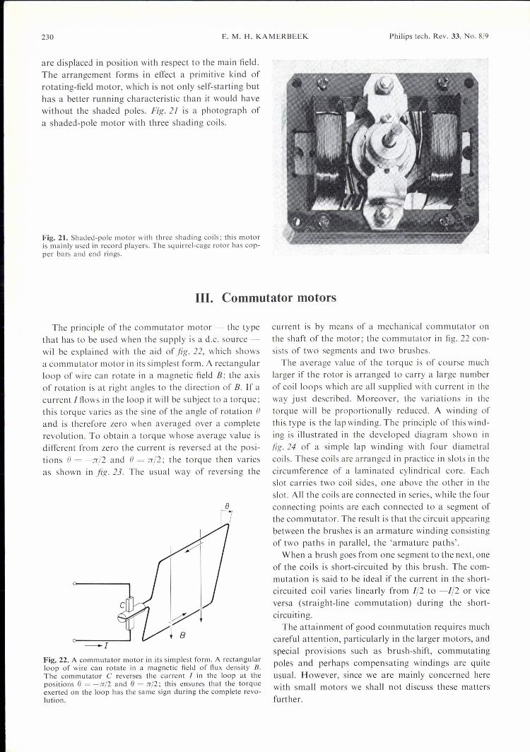
are displaced in position with respect to the main field.The arrangement forms in effect a primitive kind ofrotating-field motor, which is not only self-starting buthas a better running characteristic than it would havewithout the shaded poles. Fig. 2/ is a photograph ofa shaded-pole motor with three shading coils.
Fig. 21. Shaded-pole motor with three shading coils; this motoris mainly used in record players. The squirrel-cage rotor has cop-per bars and end rings.
Ill. Commutator motors
The principle of the commutator motor - the typethat has to be used when the supply is a d.c. source -wil be explained with the aid of fig. 22, which showsa commutator motor in its simplest form. A rectangularloop of wire can rotate in a magnetic field B; the axisof rotation is at right angles to the direction of B. If acurrent Itlows in the loop it will be subject to a torque;this torque varies as the sine of the angle of rotation ()and is therefore zero when averaged over a completerevolution. To obtain a torque whose average value isdifferent from zero the current is reversed at the posi-tions ()= -n/2 and ()= n/2; the torq ue then variesas shown in fig. 23. The usual way of reversing the
-I
Fig. 22. A commutator motor in its simplest form. A rectangularloop of wire can rotate in a magnetic field of flux density B.The commutator C reverses the current 1 in the loop at thepositions e = -n/2 and e = n/2; this ensures that the torqueexerted on the loop has the same sign during the complete revo-lution.
current is by means of a mechanical commutator onthe shaft of the motor; the commutator in fig. 22 con-sists of two segments and two brushes.
The average value of the torque is of course muchlarger if the rotor is arranged to carry a large numberof coilloops which are all supplied with current in theway just described. Moreover, the variations in thetorque will be proportionally reduced. A winding ofthis type is the lap winding. The principle of this wind-ing is illustrated in the developed diagram shown infig. 24 of a simple lap winding with four diametralcoils. These coils are arranged in practice in slots in thecircurnference of a laminated cylindrical core. Eachslot carries two coil sides, one above the other in theslot. All the coils are connected in series, while the fourconnecting points are each connected to a segment ofthe commutator. Tbe result is that the circuit appearingbetween the brushes is an armature winding consistingof two paths in parallel, the 'armature paths'.
When a brush goes from one segment to the next, oneof the coils is short-circuited by this brush. The com-mutation is said to be ideal if the current in the short-circuited coil varies linearly from 1/2 to -1/2 or viceversa (straight-line cornrnutation) during the short-circuiti ng.
The attainment of good commutation requires muchcareful attention, particularly in the larger motors, andspecial provisions such as brush-shift, commutatingpoles and perhaps cornpensating windings are quiteusual. However, since we are mainly concerned herewith small motors we shall not discuss these mattersfurther.

Philips tech. Rev. 33, No. 8/9 ELECTRIC MOTORS 231
If a d.c. current is applied to the brushes, then eachcoil ofthe armature winding takes an a.c. current whosewaveform is approximately a square wave. The com-mutator ensures that the angular frequency of thissquare wave always corresponds to the angular velocityof the rotor; it functions effectively as a frequency con-verter. In this case it converts the zero frequency of thed.c. current into a frequency corresponding to the rotorspeed.
lt\r\/o _ e 2rr
Fig. 23. The torque exerted on the loop of fig. 22, as a functionof the angle e.
IIo
III
2rr
Fig. 24. Development of a lap winding consisting of four dia-metral coils. Each coil is uppermost in a slot on one side of therotor (solid lines), and at the bottom of a slot on the other side(dashed lines). The connection between each pair of coils is con-nected to a commutator segment Seg. The rotor winding givestwo armature paths, which appear in parallel between thebrushes; half the rotor current I,. Rows in each path. Nand Sindicate the north and south poles.
Torque and speed voltage
Fig.25a is a schematic diagram of a commutatormotor with a field winding on salient poles. In a motorof this construction the main field around the circum-ference of the rotor is approximately trapezoidal. If thecurrent distribution around the rotor is uniform- which means that there must be a large number ofrotor windings and hence a large num ber of segments-then the 'current packet' present in the stator field willalways be the same and the torque will be practicallyconstant. The general expression for this torque is
2"
Te = -b2f f SrBsd,pr,
o
where as before b is the radius, I the length and Sr is
the current density of the rotor. For the present it willbe sufficient to derive from this the relation
(17)
Here epI'S is the magnetic flux penetrating the rotorfrom a stator pole and C is a constant determined bythe construction of the motor.
As soon as the rotor is in motion a voltage is inducedin its conductors. The sign and magnitude of this volt-age is given by the general vector relation E = Iv X Bwhere v is the velocity of the conductor. In our casethe magnitude is equal to wrblBs, since the rotor speedat the circurnference is co-b, This voltage can be meas-ured at the rotor terminals when there is no current inthe rotor and it is externally driven. It is called thespeed voltage Er_ and from the above it is proportionalto wJep,":
The proportionality constant is the same as in (17);this follows from the power balance
Tew!' = E,.JI',
which is the same as that discussed on p. 222 for thesynchronous motor, since Erlr is equal to the electricalpower supplied less the copper losses
Here RI' is the rotor-circuit resistance, including thebrush-contact resistance (see fig. 25b).
mek~
+ --Ir
b
Fig. 25. a) D.e. commutator motor with a field winding onsalient poles. VI' voltage at rotor terminals. II' rotor current.b) Equivalent circuit for a d.c. motor. R" resistance of rotorwinding and commutator. E,. speed voltage.
To say more about the behaviour of the torque forvarying supply current, voltage or speed, we need toknow more about the motor circuit. This is because,unlike the types discussed earlier, this kind of motorhas two windings that have to be connected to thesource. There are three ways of doing this.

232 E. M. H. KAMERBEEK Philips tech. Rev. 33, No. 8/9
Three types of commutator motor
Commutator motors can be divided into three typeswith different circuits: the separately excited motor,the shunt motor and the series motor (fig. 26). In theseparately excitedmotor the field winding and the rotoreach have a separate supply that can be independentlyoperated. Motors with permanent-magnet excitationcan be included in this class, in which there is of courseno question of controlling the main field. Permanent-magnet excitation is usually only employed in smallmotors.Even though the motor with independent energiza-
tion of the field winding already has appreciable scopefor control, a starting resistance Rext is often used inthe rotor circuit, as with the other types. In largermotors the starting resistance is in fact necessary tolimit the current when starting at full mains voltage;at the instant when the motor is connected to the supplyno speed voltage has as yet appeared to oppose thesupply voltage and with no extra resistance there wouldbe a very large surge of current. From the equationsgiven earlier it followsthat the general relation betweentorque and angular velocity for the d.c. motor is
m Vr - CWrcj)rsTe = C'Prs s, + Rext
This relation can be altered by varying the three param-eters cj)rs, Vr and Rext; independent variation is onlypossible for the separately excited motor with fieldwinding. The effect of such independent variation ofthe three parameters on the torque-speed characteristicis shown diagrammatically infig. 27. It is clear from thisfigure that the d.c. motor is basically very adaptable;it is therefore very suitable for control systems.In the shunt and series motors the three parameters
cannot be varied independently. In the shunt motor thefield winding and the rotor are connected in parallelacross the supply voltage Vr (fig. 26b). If this voltagehas a constant value, cj)rs is constant and the torque-
+~t_;:___jIs
+~
~ Rext
f
Fig. 26. The three circuit arrangements that can be used with acommutator motor. a) Separately excited motor; field windingand rotor are connected to two independent sources of supply.A starting resistance Rext is connected in series with the rotor.Motors with permanent-magnet energization are also includedunder this type. b) Shunt motor; field winding and rotor areconnected in parallel across the same supply voltage. c) Seriesmotor; field winding and rotor carry the same current.
Te
1
rl>rs=2'P
(18)
Fig. 27. The changes in the torque-speed characteristic of thecommutator motor for variation of a) the stator flux rprs, b) therotor terminal voltage Vr and c) the starting resistance Rext inthe rotor circuit.
speed characteristic is a straight line with a negativeslope that can be varied by means of Rea (fig. 27c).In the series motor the field winding is in series withthe rotor (fig.26c); the main-field flux cj)rs now varieswith the rotor current Ir. When the loading torque is in-creased the speed decreases and the rotor current in-creases; consequently cj)rs also increases at lowerspeeds. Curve Se infig. 28 is an example ofthe torque-speed characteristic of a series motor; it shows thesame variation of the slope when cj)rs is varied as infig. 27a.
To determine the torque-speed characteristic of a shunt orseries motor completely we must know the relation between themain-field flux rprs and the excitation current Is. This relation isonly linear for small values; at higher values it is affected bymagnetic saturation. The relation can be measured by drivingthe motor at constant speed and measuring the voltage producedat the rotor terminals as a function of the excitation current;this gives the relation since the speed voltage is proportionalto the main field. The curve obtained in this way is called the

Philips tech. Rev. 33, No. 8/9 ELECTRIC MOTORS 233
open-circuit characteristic; jig. 29 gives a typical example. O.C.motors are usually designed to allowasmall amount of magneticsaturation under nominal operating conditions.
Te
1Se
-CVr
Fig. 28. Torque-speed characteristics for a shunt motor (curve Sh)and a series motor (curve Se) with the same nominal operatingpoint P. When the load on the motors is greater than the nominaltorque the operating point moves upwards along the curves,which in the figure are continued to the point at which the rotorcurrent has increased to the maximum permissible value (assumedto be the same for both motors). The diagram shows that theshunt motor reaches this limit at a lower torque; the shunt motoris therefore less able to withstand overload than the series motor.
Fig. 29. The main-field flux (_{JrsCPrsas a function of the energizing tcurrent Is (the 'open-circuitcharacteristic' of a d.c. mo-tor). The magnetic saturationof the stator iron for increas-ing energizing current affectsthe shape of this characteristic.
Shunt and series motors behave quite differentlywhen the load is varied. When the load is increased,the speed of a shunt motor falls only slightly. The extrapower then delivered requires a proportional increasein the rotor current. The heavy portion of the curve Shin fig. 28 indicates how the operating point moves inthis case. The heavy portion of the curve Se indicatesthe shift of the operating point for a series motor whenits rotor current increases by the same factor. Thisincrease in the rotor current also results in a highervalue for the main field, which contributes to anincrease in the delivered torque; if the torque isdoubled the rotor current only increases by about40 %, as against 100% for the shunt motor. This meansthat the series motor is more able to withstand over-load than the shunt motor. Since the applied electricalpower increases less for a series motor, the greatertorque required can only be supplied at a significantlylower speed. A particular point to note is that if theloading torque is removed the motor speed rises sharplyand will generally 'run away' to a speed above themaximum rated value.
If the series motor is supplied with a.c. current itgives a pulsating torque; with the field and rotor wind-ings connected in series the main field and the rotorcurrent are always in phase, so that their product al-
ways has the same sign. It is more difficult in this caseto achieve good commutation, since the time-varyingmain field induces an additional voltage in the rotorcoils. The stator core, and not just the rotor, also hasto be laminated to prevent eddy-current losses. A seriesmotor designed for use on either d.c. or a.c. current isknown as a universal motor. Such motors are widelyused in domestic equipment.
Brushless d.e. motor
A mechanical commutator requires periodic main-tenance, is subject to wear, is noisy in operation andcauses vibration and electrical interference. In manyapplications these effects are a nuisance or prevent theuse of a mechanical commutator. For these reasonsbrushless d.c. motors have been under development forseveral years [*l. In these motors the commutation isobtained with electronic devices.
The rotor of a small brushless d.c. motor consists ofa permanent magnet, while the stator has a multiphasewinding. The windings can be wound on salient polesor in slots in the stator circumference. In small motorsthat have to provide a pulsation-free torque, i.e. no'cogging', the windings are attached to a smooth stat orbore in the form of 'air-gap coils'. Fig. 30 gives a
+
Fig. 30. Brushless d.c. motor. Opening and closing the switchesof the four stator coils in succession produces a rotating statorfield, which pulls the permanent-magnet rotor round with it.In practice the switches are transistors or thyristors. The controlsignals for these devices are derived from the position of therotor, which can be monitored optically with' photodiodes ormagnetically with Hall elements. .
[*l We intend to include an articleoon brushless d.e. motors inthe second issue on electric motors. (Ed.)

234 - ELECTRIC MOTORS Philips tech. Rev. 33, No. 8/9
schematic diagram of a brushless d.c. motor with atwo-pole rotor and four stator windings; this arrange-ment of stat or and rotor shows considerable similarityto a four-phase synchronous motor with a permanent-magnet rotor. However, in the motor of fig. 30 thefour stator windings are supplied from a d.c. source,in a way that recalls the supply arrangements for thestepping motor. The notable difference, however, isthat the opening and closing of the switches betweenthe windings and the source are determined only bythe position of the rotor and the desired direction ofrotation. This is shown schematically infig. 31 for thecase of clockwise rotation. Apart from brief transienteffects, only two of the four windings are in use at anyone moment. In small motors the switches consistof transistors, in large motors the rather less easilyquenched thyristors are used.There are various types of brushless d.c. motor,
which can be classified by the nature of the elementsfor detecting the position of the rotor. First of all thereare the Hall elements or field-dependent resistors.These are located in the rotor field, which varies withthe position of the rotor [6]. The position of the rotorcan also be established with the aid of photoelectricdevices (photocells), magnetic [7] or electrostatic sens-ing elements. The electronic circuit is usually providedwith a speed control and current limiting, giving a veryadaptable d.c. motor that is particularly suitable forcontrol purposes. Brushless motors are very suitablefor applications where torque has to be uniform and[6) See: G. Bosch and J. H. H. Janssen, Integrated circuit with
Hall device for brushless d.c. motors, Philips tech. Rev. 31,366-368, 1970.
[7) W. Radziwill, A highly efficient small brushless d.c. motor,Philips tech. Rev. 30, 7-12, 1969.
titititi I0 11: 211:
-8
Fig. 31. Schematic representation of the cyclical variation of thefour stator currents It to f4 for the brushless d.c. motor shownin fig. 30.
efficiency high; they can be used for the drive in bat-tery-operated tape recorders and record players with-out the need for an intermediate transmission system.
Summary. The most important types of electric motor are de-scribed and the main characteristics are derived. Electric motorscan be classified as a.c. or d.c. motors. A.C. motors are eithersynchronous or asynchronous. In synchronous motors the num-ber of revolutions per second is equal to the frequency of thesupply divided by the number of pairs of poles. The stator wind-ings maintain a rotating stator field, which the rotor follows;the rotor can be either a permanent-magnet rotor or made froma materialof high permeability (and non-cylindrical) in thereluctance motor, or of material with considerable hysteresis(hysteresis motor). In the asynchronous or induction motor therotor has closed current circuits in which currents are induced;the rotor 'slips' with respect to the rotating stator field. O.C.motors have a commutator, which reverses the current in thewindings after every half-revolution. The commutator usuallyconsists of brushes and sliding-contact segments, but electroniccommutation is sometimes employed (brushless d.c. motor). Ifthe commutator motor is series wound it can also be run on a.c.current (universal motor).