Embed Size (px)
Citation preview

Eco TechELECTRIC STEAM COOKER
MODELS:ET-3EET-5EET-6ESB-ET-3ESB-ET-6E
COVERING• INSTALLATION• OPERATION• SERVICE & PARTS
INSTALLATION AND OPERATION MANUAL
An Employee-Owned Company
35 Garvey Street • Everett, MA 02149-4422 USATel: (617) 387-4100 • Fax: (617) 387-4456Outside MA Fax: 1-800-227-2659 E-mail: [email protected] Web site: www.mfii.comForm No. S-2501 REV. E 5/03 Printed In U.S.A
®

Table of ContentsPARAGRAPH PAGE
SECTION 1 INTRODUCTION
1.1 Description ................................................... 1-11.2 Basic Functioning ........................................ 1-11.3 Service .......................................................... 1-1
SECTION 2 INSTALLATION
2.1 Assembly ..................................................... 2-12.2 Setting in Place ............................................. 2-12.3 Service Connections .................................... 2-12.3.1 Electrical Connections .................................. 2-12.4 Reversing the Doors .................................... 2-1
SECTION 3 INITIAL SYSTEMS INSPECTION
3.1 General ......................................................... 3-13.2 Warm-up ...................................................... 3-13.3 Timed Steam Mode ...................................... 3-13.4 Constant Steam Mode .................................. 3-13.5 Hold Mode ................................................... 3-13.6 High / Low Power Mode .............................. 3-13.7 Low Water Warning ..................................... 3-13.8 Shut Down ................................................... 3-1
PARAGRAPH PAGE
SECTION 4 OPERATION
4.1 Controls and Indicators ............................... 4-14.2 Operating Procedures .................................. 4-14.2.1 Startup and Preheating ................................. 4-14.2.2 Cooking—Mechanical Controls ................... 4-14.2.3 Shutdown and Daily Cleaning ...................... 4-24.3 Periodic Cleaning ......................................... 4-2
SECTION 5 TROUBLESHOOTING
5.1 General ......................................................... 5-1
SECTION 6 MAINTENANCE
6.1 General ......................................................... 6-16.2 Daily Cleaning .............................................. 6-16.3 Preventive Maintenance .............................. 6-16.4 Periodic Cleaning ......................................... 6-16.5 Control Panel Electrical Service Access ....... 6-26.6 Door Adjustment ......................................... 6-26.6.1 Door Alignment ........................................... 6-26.6.2 Door Latch Tension Adjustment ................. 6-26.6.3 Door Handle Tension Adjustment ............... 6-36.7 Door Gasket Replacement ............................ 6-36.8 Heating Element Replacement ....................... 6-116.9 Ship-Board Assembly Replacement.............. 6-13
i
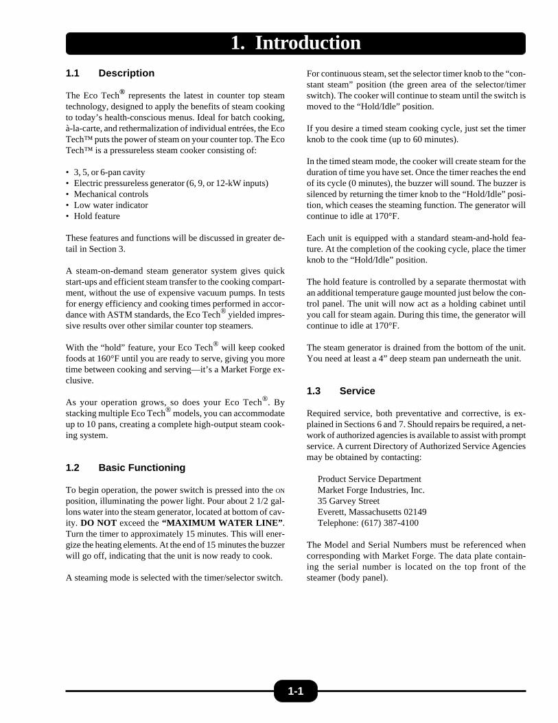
1. Introduction1.1 Description
The Eco Tech® represents the latest in counter top steamtechnology, designed to apply the benefits of steam cookingto today’s health-conscious menus. Ideal for batch cooking,à-la-carte, and rethermalization of individual entrées, the EcoTech™ puts the power of steam on your counter top. The EcoTech™ is a pressureless steam cooker consisting of:
• 3, 5, or 6-pan cavity• Electric pressureless generator (6, 9, or 12-kW inputs)• Mechanical controls• Low water indicator• Hold feature
These features and functions will be discussed in greater de-tail in Section 3.
A steam-on-demand steam generator system gives quickstart-ups and efficient steam transfer to the cooking compart-ment, without the use of expensive vacuum pumps. In testsfor energy efficiency and cooking times performed in accor-dance with ASTM standards, the Eco Tech® yielded impres-sive results over other similar counter top steamers.
With the “hold” feature, your Eco Tech® will keep cookedfoods at 160°F until you are ready to serve, giving you moretime between cooking and serving—it’s a Market Forge ex-clusive.
As your operation grows, so does your Eco Tech®. Bystacking multiple Eco Tech® models, you can accommodateup to 10 pans, creating a complete high-output steam cook-ing system.
1.2 Basic Functioning
To begin operation, the power switch is pressed into the ON
position, illuminating the power light. Pour about 2 1/2 gal-lons water into the steam generator, located at bottom of cav-ity. DO NOT exceed the “MAXIMUM WATER LINE”.Turn the timer to approximately 15 minutes. This will ener-gize the heating elements. At the end of 15 minutes the buzzerwill go off, indicating that the unit is now ready to cook.
A steaming mode is selected with the timer/selector switch.
For continuous steam, set the selector timer knob to the “con-stant steam” position (the green area of the selector/timerswitch). The cooker will continue to steam until the switch ismoved to the “Hold/Idle” position.
If you desire a timed steam cooking cycle, just set the timerknob to the cook time (up to 60 minutes).
In the timed steam mode, the cooker will create steam for theduration of time you have set. Once the timer reaches the endof its cycle (0 minutes), the buzzer will sound. The buzzer issilenced by returning the timer knob to the “Hold/Idle” posi-tion, which ceases the steaming function. The generator willcontinue to idle at 170°F.
Each unit is equipped with a standard steam-and-hold fea-ture. At the completion of the cooking cycle, place the timerknob to the “Hold/Idle” position.
The hold feature is controlled by a separate thermostat withan additional temperature gauge mounted just below the con-trol panel. The unit will now act as a holding cabinet untilyou call for steam again. During this time, the generator willcontinue to idle at 170°F.
The steam generator is drained from the bottom of the unit.You need at least a 4” deep steam pan underneath the unit.
1.3 Service
Required service, both preventative and corrective, is ex-plained in Sections 6 and 7. Should repairs be required, a net-work of authorized agencies is available to assist with promptservice. A current Directory of Authorized Service Agenciesmay be obtained by contacting:
Product Service DepartmentMarket Forge Industries, Inc.35 Garvey StreetEverett, Massachusetts 02149Telephone: (617) 387-4100
The Model and Serial Numbers must be referenced whencorresponding with Market Forge. The data plate contain-ing the serial number is located on the top front of thesteamer (body panel).
1-1
2.1 Assembly
The assembled Eco Tech® Pressureless Steam Cooker isshipped in a carton on a skid. Steps required for assembly areas follows:
1. Remove the carton and the unit off the skid.
2. Install the feet into the threaded mounting locations onthe bottom of the unit.
3. Install a rack supports to the left & right insideof thecooking cavity mounting holes.
4. Install the vent strainer in the back inside the cookingcavity.
5. Mount the drip trough to the front of the unit.
6. Slide the ala-carte shelf into place on the slide guides.
2.2 Setting in Place
If possible, a location should be selected under an exhausthood which will remove small amounts of vapor emitted fromthe cooker during normal operation. Next, level the unit afterit is placed in its final location. This is accomplished by turn-ing the bottom part of the adjustable feet. Using the cabinettop as a reference, obtain level adjustment left-to-right andfront-to-back. MAKE SURE UNIT IS LEVEL
2.3 Service Connections
The only service connection at the back of the unit is theelectrical connection. Please see the illustrations and tablelocated in Table 2.1 for service connections, details, and di-mensions.
2.3.1 Electrical Connections
CAUTION: USE COPPER WIRE ONLY FOR POWERSUPPLY CONNECTIONS.
Please refer to Table 2.1 for details of electrical service con-nections.
Electrical connection power supply should utilize wire suit-able for 90°C.
2.4 Reversing the Doors
The Eco Tech® Pressureless Steam Cooker has a reversiblecooking compartment door for your convenience. This sec-tion contains instructions for reversing this door.
1. Turn off power to the unit.
2. Open the cooking compartment door
3. Remove the two screws that attach the top hinge to thefront of the unit.
4. Slide the door upwards, off the bottom hinge.
5. Remove the two screws that attach the bottom hinge tothe front of the units.
6. Remove the right and left side panels by unscrewing the1 screw on each panel and sliding the panel down.
2-1
2. Installation
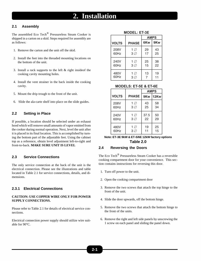
Note: ET-3E 9kW & ET-5/6E 12kW factory options
Table 2.0
VOLTS
208V60Hz
240V60Hz
480V60Hz
6Kw
29�17�
25�15�
13�7
9Kw
43�25�
�38�22�
�19�11
PHASE
1 E�3 E�
�1 E�3 E�
�1 E�3 E
MODEL: ET-3EAMPS
VOLTS
208V60Hz
240V60Hz
480V60Hz
9Kw
43�25�
�37.5�22�
�19�11
12Kw
58�34�
�50�29�
�25�15
PHASE
1 E�3 E�
�1 E�3 E�
�1 E�3 E
MODELS: ET-5E & ET-6EAMPS
VOLTS
208V60Hz
240V60Hz
480V60Hz
6Kw
29�17�
25�15�
13�7
9Kw
43�25�
�38�22�
�19�11
PHASE
1 E�3 E�
�1 E�3 E�
�1 E�3 E
MODEL: ET-3EAMPS
VOLTS
208V60Hz
240V60Hz
480V60Hz
9Kw
43�25�
�37.5�22�
�19�11
12Kw
58�34�
�50�29�
�25�15
PHASE
1 E�3 E�
�1 E�3 E�
�1 E�3 E
MODELS: ET-5E & ET-6EAMPS
VOLTS
VOLTS
6Kw
208V60Hz
208V
9Kw
9Kw
29�17�
60Hz
25�15�
240V
12Kw
43�25�
�37.5�22�
�19�11
PHASE
43�25�
�38�22�
�19�11
13�7
60Hz
240V
MODEL: ET-3E
60Hz
PHASE
58�34�
�50�29�
�25�15
1 E�3 E�
�1 E�3 E�
�1 E�3 E
480V
AMPS
60Hz
480V
1 E�3 E�
�1 E�3 E�
�1 E�3 E60Hz
AMPS
VOLTS
208V60Hz
240V60Hz
480V60Hz
6Kw
29�17�
25�15�
13�7
9Kw
43�25��
38�22��
19�11
PHASE
1 E�3 E�
�1 E�3 E�
�1 E�3 E
MODEL: ET-3EAMPS
VOLTS
208V60Hz
240V60Hz
480V60Hz
9Kw
43�25��
37.5�22��
19�11
12Kw
58�34��
50�29��
25�15
PHASE
1 E�3 E�
�1 E�3 E�
�1 E�3 E
MODELS: ET-5E & ET-6EAMPS

2. Installation (continued)
7. Remove the door interlock assembly by unscrewing thetwo nuts that hold it in place (assembly is attached to thescrews in the top right hinge mounting holes,see fig. 2-1).
8. Remove the four screws in the right side hinge mountingholes and install them in the left side hinge mountingholes (where the hinges were originally mounted).
9. Using the nuts removed in step #6, reinstall the door in-terlock assembly onto the 2 screws in the lower left hingemounting holes (see fig. 2-1) by moving the assemblyover the cooking cavity to the other side of the unit.Rotate the door interlock assembly 180° for installa-tion, so that the switch is now facing up.
10. Reinstall the top hinge and screws into the right lowerhinge mounting holes. Rotate the hinge 180° for in-stallation, so that the pin which the door rides on is nowfacing up. The hinge must be rotated because it will nowfunction as the bottom hinge. DO NOT COMPLETELYTIGHTEN THE HINGE MOUNTING SCREWS YET.These will be used later for adjusting the door.
11. Remove the door latch assembly from the face of the unit.The 2 nuts mounting the door latch are located behindthe face of the unit and must be accessed where the rightside panel was removed.
12. Remove the two white hole plugs from the left door latchmounting holes, and insert them into the right door latchmounting holes (where the door latch assembly wasoriginally mounted).
13. Rotate the door latch assembly 180°, and install intothe left door latch mounting holes.
NOTE: Each stud on the latch assemblyshould have a plastic washer, a spring, a plasticwasher and a Nyloc type nut,
14. To adjust the tension of the door latch, tighten both nutsdown until the springs are fully compressed, then backeach nut off 1 1/2 turn.
15. Rotate the door 180° for mounting.
16. Slide the remaining hinge into the top door bearing.
17. Slide the door and hinge assembly down onto the hingewhich you have already mounted to the front of the unit.Use the two screws to mount the top hinge into the rightupper hinge mounting holes. DO NOT COMPLETELYTIGHTEN THE HINGE MOUNTING SCREWS YET.
18. Slowly push the cooking compartment door closed untilit is latched.
19. The cooking compartment door can now be raised, low-ered, and/or rotated into position by bumping it with thepalm of your hand or by using a small rubber mallet.
20. First, check the alignment at the front of the door bymaking sure that the striker in the door is centered withthe latch mechanism on the front of the unit.
21. Square the door to the unit by raising or lowering thehinge side of the door, keeping the latch centered withthe striker.
22. Visually inspect the door. Be sure that the door is squareto the unit, the striker is centered with the latch, and thegasket is in contact with the entire lip of the cookingcompartment.
23. Gently open the cooking compartment door, taking carenot to move it out of position.
24. Tighten all 4 door hinge bracket mounting screws.
25. Close and visually inspect the door again, as describedin step 22.
26. Reinstall the left and right side panels, using the screwsfor each panel.
2-2

2. Installation (continued)
TOP LEFT HINGEMOUNTING HOLES
LEFT DOOR LATCHMOUNTING HOLES
INTERLOCK ASSEMBLYPOSITION WHEN DOOR ISREVERSED
LOWER LEFT HINGEMOUNTING HOLES
TOP RIGHT HINGEMOUNTING HOLES
INTERLOCK ASSEMBLYORIGINAL POSITION
DOOR LATCH ASSEMBLYORIGINAL POSITION
LOWER RIGHT HINGEMOUNTING HOLES
Fig. 2.1: Door Reversability
2-3

INTERNAL DIMENSIONSModel Height Width Depth
ET-3E10.7" 14.0" 22.5"271 mm 356 mm 571 mm
ET-5 & 6E17.2" 14.0" 22.5"436 mm 356 mm 571 mm
2. Installation (continued)
Table 2.1: Service Connections
2-4
Note: Water used in this unit, should have hardness of no greater than 2.0 grains per gallon and pH level iswithin the range of 7.0-8.5. Water which fails to meet these standards should be treated by installation of awater conditioner. Equipment failure caused by inadequate water quality is not covered under warranty.
CAPACITYPan Size Number of Pans
ET-3E ET-5E ET-6E
12" x 20" x 1" 6 8 10
12" x 20" x 21/2" 3 5 6
12" x 20" x 4" 2 3 4
30"[762 mm]
1.5"[38 mm]
24"[610 mm]
3"[76 mm]
EECW Optional - Auto Water
Feed (Cold)
18.8"(447 mm)
4"[102 mm]
2"[51 mm]
SEEBELOW
Model5 & 6 Pan
3 Pan
Height28" [712 mm]
21.5" [546 mm]
TOP VIEW
REAR VIEW
D Optional - Drain Kit
CW
D
6.5" (165mm)9.63" (245mm)
E = Electrical ConnectionCW = Semi-Auto Water Feed (Factory Option)
D = Drain Kit (Factory Option)

2. Installation (continued)
Fig. 2.2: Wiring Diagram
2-5
FRONT PANEL

3. Initial Systems Inspection3.1 General
This section contains information for you to test and familiar-ize yourself with the operation of the Eco Tech™.
After the cooker is completely assembled, all packaging mate-rials removed, and all service connections are made, all sys-tems must be given a thorough checkout before being putinto operation. We begin by making sure that the drain valveis closed and the empty drain pan is in its proper position.Pour about 2 1/2 gallons of water into the bottom of the cook-ing cavity or up to the “MAXIMUM WATER LINE”.Mount both racks and the Ala - Carte - Shelf in place.Confirm that all service connections are correct. Close thecooking compartment door, and turn the timer knob to15 minutes.
3.2 Warm-up
Push the power switch to the “ON” position. The heaters willenergize. After 15 minutes the buzzer will go off, indicatingthat the steamer is ready to cook. The temperature gauge willindicate a 212°F temperature. At this time you may chooseeither to load food to cook or turn the timer knob to “hold /idle” mode prior to actual cooking. In the hold / idle mode,the temperature gauge will show a temperature of around170°F.
3.3 Timed Steam Mode
Set the selector/timer knob to 10 minutes and close the door.The temperature gauge will slowly register increasing tem-peratures up to 212°F.
When the timer reaches 0 minutes, the buzzer will sound.The buzzer is silenced by returning the selector/timer knobto the “hold / idle” position.
3.4 Constant Steam Mode
The constant steam mode overrides all other cooking modes.This mode is entered by turning the selector/timer knob tothe “constant steam” position on the dial (green area). Withthe knob set for constant steam, and the door closed, the tem-perature gauge should indicate a temperature of 212°F.
3.5 Hold / Idle Mode
You enter this mode by placing the selector/timer knob to the“Hold / Idle” position. This mode only works if the steamingcycle has been completed and the door has been left closed.The cooking cavity will hold product between 150°F - 190°F
3.6 High / Low Power Switch
Your Eco-Tech® comes with a unique “High / Low Power”system. This feature allows smaller portions to be cookedwith less power. If your menu demands are reduced, theEco - Tech allows you to save energy. This is a Market Forgeexclusive!
3.7 Low Water Signal
During cooking, the water in the steam generator will keepevaporating. When the generator is nearly empty, the heat-ers, for safety reasons, will be turned off and a beeper willsound, indicating an abrupt end to the cooking mode and aneed to add water until the beeper turns off.
3.8 Shut Down
No special procedure is necessary for shutting the unit down.Simply press the power switch into the “OFF” position, andopen the drain valve at the bottom. The indicator lights onthe control panel will go out, and the generator will drain.Then empty the drain pan.
Caution: When the unit is not in use, leave the cookingcompartment door slightly ajar to prolong the life of thedoor gasket.
3-1

4. Operation4.1 Controls and Indicators
The controls and indicators used to operate the Eco Tech®
pressureless steam cooker are listed and described inTable 4.1.
4.2 Operating Procedures
This section includes general instructions for daily operationof the Eco Tech™ pressureless steam cooker. You should re-view Sections 3.1 through 3.6 of this manual if you are unfa-miliar with the functions of the Eco Tech™. If you requiremore detailed technical information on the various EcoTech™ systems and their functions, please refer to Section 5of this manual, “Principles of Operation.”
4.2.1 Startup and Preheating
The Eco Tech™ pressureless steam cooker requires a simplestartup procedure:
1. With the drain closed, pour clean water into the emptysteam generator up to the “ MAXIMUM WATERLINE”
2. Press the power switch into the “on” position.
3. With the door closed, turn the timer knob to 15 minutes.
The heaters will be energized. After 15 minutes, the buzzer willgo off, indicating that the steamer is ready to cook. You mayat this time either decide to cook in a constant steam/timermode or turn the timer knob to “hold/idle” mode to idle thesteamer around 170°F.
4.2.2 Cooking—Mechanical Controls
Note: The temperature gauge needs to indicatetemperatures above 150°F before cooking.
1. Slide pans of food into the cooking compartment pansupport racks.
2. Firmly close the cooking compartment door.
3. Begin steaming by rotating the selection/timer knob toeither the constant steam position or a desired cookingtime.
4. At the end of the cook cycle (the buzzer will sound whenthe timer has timed out to zero), return the timer knob tothe “Hold/Idle” position, which will turn off the buzzer.
5. If the unit is in constant steam mode, it will continue toprovide steam to the cavity until the selector/timer isturned to the “Hold/Idle” position. Opening the door willinterrupt the flow of steam to the cavity.
4-1
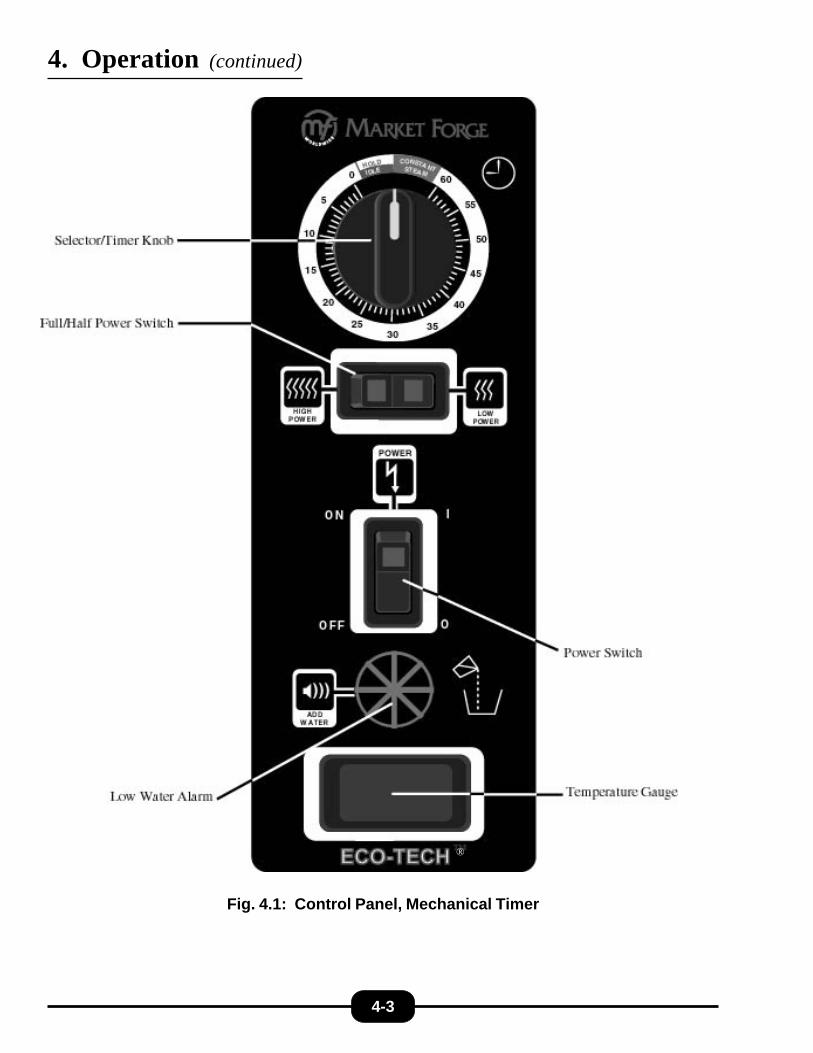
Power SwitchLocated in the middle of the control panel. Pressing this button into the “on” position willsupply power to the unit. Pressing this button into the “off” position will cut off power tothe generator.
Timer Knob Located near the top of the control panel. Turn the timer knob to set the cook time.
Temperature GaugeLocated at the bottom of the control panel, it is used to monitor the internal temperatureof the cooking compartment during the steam or “Hold/Idle” mode.
Constant Steam PositionLocated on the timer knob (selection/timer switch), the constant steam feature is enteredby turning the knob clockwise to the green area (marked constant steam).
No Water AlarmLocated below the power switch of the control panel. This will give an audible signalwhen the generator needs to be refilled with clean water.
Table 4.1: Controls and Indicators
High & Low Power SwitchLocated on the control panel just below the 60 Minute Timer. This switch allows theend user to choose between power options. “HIGH” mode is for full capacity.“LOW” mode is for reduced capacity.

4. Operation (continued)
4.2.3 Shutdown and Daily Cleaning
After each period of daily operation, the steamer should bedrained and cleaned. Simply press the power switch into the“OFF” position, and follow the cleaning steps outlined below.
1. Place an empty 4" deep steam pan under the steamer,and turn drain valve to “OPEN.” Allow all water to drain& cool before emptying the pan.
2. Allow the steamer to cool before removing rear strainer,left and right racks, and ala-carte shelf.
3. Wash cooking compartment and steam generator interi-ors using a mild detergent. Rinse and dry thoroughly.
4. Remove drip/spill trough.
5. Wash all removed pieces with a mild detergent and non-abrasive pad. Rinse and dry thoroughly.
6. Replace all removed parts.
7. Leave the door slightly ajar to prolong life of the doorgasket.
4.3 Periodic Cleaning
If you should experience build up of lime or mineral depositsin the steam generator, it may be cleaned easily using vin-egar & water. If dealing with severe scaling use MarketForge’s descaling product, “Total Concept™” with water.
1. With drain closed, fill generator with 2 gallons waterand 1/2 gallon vinegar. Close door
2. Turn power switch to “ON”.
3. Place timer into “HOLD” mode. Let run for one hour.
4. Open door. Turn the drain valve to “OPEN.” Allow Vin-egar/Water solution to drain into the pan. Empty asneeded.
5. Refill steamer with water, and drain again flushing outany remaining vinegar/water solution. Empty as needed.
6. Replace any removed parts, close valve, and refillsteamer. Steamer is now ready for use.
7. If “Total Concept” is needed repeat above procedure, replacing vinegar with “Total Concept”.
4-2
4. Operation (continued)
Fig. 4.1: Control Panel, Mechanical Timer
4-3
®

5. Troubleshooting5.1 General
The information in this section is intended to assist the op-erator, maintenance and the service personnel in locating thesource of problems which may occur with the cooker. Be-fore following any of the procedures given in this section,
the operator/maintenance person should be thoroughly fa-miliar with Section 4 (“Operation”) of this manual.
If the problem cannot be readily corrected without the use oftools, the operator/maintenance person should contact thenearest Market Forge service agency for assistance.
5-1
TROUBLE POSSIBLE CAUSE REMEDY
POWER light does not come onwhen the POWER switch ispressed into the on position.
1. No power to unit.
2. Fuse blown.
3. Faulty POWER switch.
1. Be sure the power supply is on.
2. Replace fuse.
3. Check/replace POWER switch(P/N 08-6549).
Steam continuously leaksthrough the door gasket.
1. Misaligned door.
2. Faulty pressure switch.
1. Check to be sure cooking compart-ment door is properly aligned. (SeeSection 6.7.)
2. Replace the pressure switch(P/N 08-6502).
Steam generator will not fill. 1. Open drain valve. 1. Close drain valve.
Generator will not createsteam.
1. 208/240/480 power supply is notconnected or not turned on.
2. Cooking compartment door is ajar.
3. Cooking compartment door is ajar.
4. Faulty door magnet or magnetic reedswitch.
5. Lime buildup in the steam generator.
6. Faulty circuit breaker.
7. Faulty control panel TIMER.
1. Check to be sure 208/240/480 poweris connected and on.
2. Check to be sure that the cookingcompartment door is closed andlatched.
3. Check to be sure cooking compart-ment door is properly aligned.
4. Check magnet (P/N 08-5027) and reedswitch (P/N 08-6308). Replace ifneeded.
5. Clean the generator per Section 4.3.
6. Check circuit breaker at your 208/240/480 volt service connection. Reset ifnecessary.
7. Check/replace control panel Timer ifnecessary (P/N 08-6563).

5. Troubleshooting (continued)
5-2
TROUBLE POSSIBLE CAUSE REMEDYGenerator will not create steam
(continued)8. Faulty heaters. 8. Check/replace heaters.
9. Wiring short. 9. Check wiring at terminals.
10. No water in generator. 10. Add 2 gallons of water.
Generator continues to createsteam when the cookingcompartment door isopened.
1. Faulty magnet reed switch (contactsfailed closed).
1. Check magnetic reed switch Replaceif neccesary (P/N 08-6308).
11. Faulty exhaust valve.. 11. Check/replace exhaust valve (P/N 08-4952).
12. Faulty preheat thermostat. 12. Check/replace preheat thermostat (P/N 08-6586)
13. Faulty pressure switch. 13. Check/replace w.c. pressure switch(P/N’s 08-6502 & 08-6580)
2. Wiring short.. 2. Checking wiring at terminals.
Generator dosen’t drain whenthe drain valve is opened.
1. Clogged or kinked generator drainline.
1. Check to be sure that the generatordrain line is not kinked and is free ofdebris.
2. Clogged generator drain hole. 2. Check to be sure the generator drainhole is free of debris.
Steamer fails to hold. 1. Faulty hold thermostat. 1. Replace (P/N 08-6588).
2. Faulty contactor. 2. Replace (P/N 10-5944)
2. Faulty timer. 3. Replace (P/N 08-6464)
6. Maintenance6.1 General
This section contains both preventive and corrective mainte-nance information. Preventive maintenance may be per-formed by maintenance personnel at the establishment inwhich the cooker is installed. It is recommended that userpersonnel never attempt to make repairs or replacements tothe equipment. Assistance in service methods or a currentdirectory of authorized agencies may be obtained from Mar-ket Forge Industries.
6.2 Daily Cleaning
After each period of daily operation (more frequently as re-quired to maintain cleanliness), the cooker should be thor-oughly cleaned by completing the following steps:
1. Place a 4" deep steam pan under the steamer, and turndrain valve to “OPEN.” Allow all water to drain beforeemptying the pan.
2. Allow the steamer to cool before removing rear strainer,left and right racks, and ala-carte shelf..
3. Wash cooking compartment and steam generator interi-ors using a mild detergent. Rinse and dry thoroughly.
4. Remove drip/spill trough.
5. Wash all removed pieces with a mild detergent and non-abrasive pad. Rinse and dry thoroughly.
6. Replace all removed parts.
7. Leave the door slightly ajar to prolong life of the doorgasket.
6.3 Preventive Maintenance
A good preventive maintenance program begins with thedaily cleaning procedure described above. Additional pre-ventive maintenance operations are presented in this section.In establishments that employ full-time maintenance person-nel, the tasks described can be assigned to them. For otherinstallations, tasks requiring mechanical or electrical experi-ence must be performed by an authorized service agency.
CAUTION: Under no circumstances should hardware (orparts) be replaced with a different size or type other than asspecified in the parts list. The hardware used in the cookerhas been selected or designed specifically for its application,and the use of other hardware may damage the equipment,can present a safety hazard, and will void any warranty.
The following sections set forth minimum preventive mainte-nance procedures that must be completed periodically to as-sure continued trouble-free operation.
6.4 Periodic Cleaning
If you should experience build up of lime or mineral depositsin the steam generator, it may be cleaned easily using vin-egar & water. if dealing with severe scaling use MarketForge's descaling product, “Total Concept™” with water.
1. With drain closed, fill generator with 2 gallons waterand 1/2 gallon vinegar. Close door.
2. Turn power switch to “ON”.
3. Place timer into “HOLD” mode. Let run for one hour.
4. Open door. Turn the drain valve to “OPEN”. Allow Vin-egar/Water solution to drain into the pan. Empty asneeded.
5. Refill steamer with water, and drain again flushing outany remaining vinegar/water solution. Empty as needed.
6. Replace any removed parts, close valve, and refillsteamer. Steamer is now ready for use.
7. If “Total Concept™” is needed repeat above procedure,replacing vinegar with “Total Concept™”.
6-1

6. Maintenance (continued)
6.5 Control Panel ElectricalService Access
The control panel assembly is mounted on the front of theunit. It houses all the controls and indicators that are used tooperate the Eco Tech®. In order to service any of the controlpanel electrical components, the control panel assembly mustbe removed from the front of the unit.
CAUTION: Be sure to disconnect the power supply fromthe unit before servicing any electrical components.
PROCEDURE
1. Remove the 6 screws that fasten the control panel as-sembly onto the front of the unit.
2. Gently move control panel assembly out away from unit.
NOTE: A ground strap acting as a restraint prevents thecontrol panel from putting unnecessary strain on wiresand connections.
6.6 Door Adjustment
The cooking compartment door alignment, door handle ten-sion, and latch tension are preadjusted at the factory duringassembly. During normal usage, these should not need anyattention. Note that when the cooking compartment doorsare reversed, as described in Section 2.3 of this manual, thedoors will need to be aligned and the door latch tension willneed to be adjusted (the door handle will not need adjust-ment when the door is reversed).
6.6.1 Door Alignment
The cooking compartment doors are prealigned at the fac-tory during assembly and should not need adjusting unlessthey are reversed. Should the doors need realignment, theprocedure is as follows:
PROCEDURE
1. Open the cooking compartment door.
2. Loosen all screws (2 per hinge) that mount the upperand lower hinge brackets to the face of the unit using aflathead screwdriver. DO NOT REMOVE THESCREWS.
3. Begin to retighten all 4 screws so that they are snugagainst the face of the unit. DO NOT COMPLETELYTIGHTEN THE SCREWS.
4. Slowly push the cooking compartment door closed untilit is latched.
5. The cooking compartment door can now be raised, low-ered, and/or rotated into position by bumping it with thepalm of your hand or by using a small rubber mallet.
6. First, check the alignment at the front of the door bymaking sure that the striker in the door is centered withthe latch mechanism on the front of the unit.
7. Square the door to the unit by raising or lowering thehinge side of the door, keeping the latch centered withthe striker.
8. Visually inspect the door. Be sure that the door is squareto the unit, the striker is centered with the latch, and thegasket is in contact with the entire lip of the cookingcompartment.
9. Gently open the cooking compartment door, taking carenot to move it out of position.
10. Tighten all 4 door hinge bracket mounting screws usinga flathead screwdriver.
11. Close and visually inspect the door again, as describedin Step 8.
6-2
6. Maintenance (continued)
6.6.2 Door Latch Tension Adjustment
Caution: Shut off main electrical power to unit.
PROCEDURE
1. Open the cooking compartment door.
2. Remove the control panel as described in section 6.5.
3. Tighten both nuts on the back of the latch until thesprings are fully compressed.
4. Back each nut off 1 1/2 turn.
5. Remount the control panel.
6.6.3 Door Handle Tension Adjustment
PROCEDURE
1. Open the cooking compartment door.
2. Remove the 6 screws and washers from the top edge andfrom the bottom edge of the door.
3. Remove the inner door gasket mounting plate assemblyfrom the outer door. Do not disassemble these three com-ponents—remove them as an assembly.
4. Tighten both nuts on the back of the handle until thesprings are fully compressed.
5. Back each nut off 1 1/2 turn.
6. Remount the inner door gasket mounting plate assemblyby assembling the 6 screws and washers.
6.7 Door Gasket Replacement
The cooking compartment door gaskets are made of a siliconetype rubber material, which is very durable but subject towear during normal operation. Should the gasket leak, read-just the door gasket to the unit or replace it.
PROCEDURE: REPLACE GASKET
1. Open the cooking compartment door.
2. Remove the (3) screws from the top of the door, and the(3) screws from the bottom of the door.
3. Remove the inner door, gasket plate and gasket.
4. Remove the (6) nuts on the back of the inner door.
5. Remove the door gasket mounting plate and the doorgasket.
6. Install the new door gasket (REF. Table 7.3 for part num-ber) to the mounting plate.
7. Reassemble the mounting plate with gasket to the innerdoor using the (6) nuts.
NOTE: Remember that the lip on the door gasketmounting plate must fit into the channel on the insideedge of the gasket to insure a proper seal.
8. Reassemble the inner door, mounting plate, and gasketwith the outer door using the (3) screws on the top andbottom of the dooor.
PROCEDURE: TO ADJUST GASKET TO UNIT
To prevent steam leaks around the door, adjust the gaskettension to cavity. Adjust the gasket by loosening the 6 screwson top and bottom of door, move inner door plate in or out,left side or right side, and tighten the 6 screws.
6-3
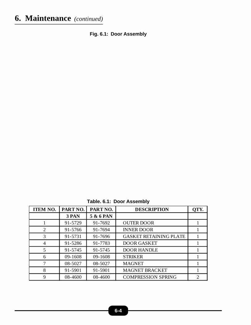
ITEM NO. PART NO. PART NO. DESCRIPTION QTY.3 PAN 5 & 6 PAN
1 91-5729 91-7692 OUTER DOOR 12 91-5766 91-7694 INNER DOOR 13 91-5731 91-7696 GASKET RETAINING PLATE 14 91-5286 91-7783 DOOR GASKET 15 91-5745 91-5745 DOOR HANDLE 16 09-1608 09-1608 STRIKER 17 08-5027 08-5027 MAGNET 18 91-5901 91-5901 MAGNET BRACKET 19 08-4600 08-4600 COMPRESSION SPRING 2
6. Maintenance (continued)
Fig. 6.1: Door Assembly
6-4
Table. 6.1: Door Assembly

ITEM NO. PART NO. DESCRIPTION QTY.1 91-7690 BRACKET, REED SWITCH 12 08-6308 REED SWITCH 13 10-2512 WASHER, STAR 24 10-1979 SCREW, 4-40 X 7/16" LG 25 10-2524 LOCK WASHER 26 10-2380 NUT, 4-40 2
Table 6.2: Reed Switch Subassembly Part List
6. Maintenance (continued)
6-5
NOTE: REED SWITCH ASSEMBLY IS LOCATED ON INSIDE OF FRONT FRAME
Fig 6.2: Reed Switch Subassembly Part List

ITEM NO. PART NO. PART NO. DESCRIPTION QTY.3-PAN 5 & 6-PAN
1 91-5700 91-7699 RACK 12 91-6910 91-6911 PANEL, SIDE 23 91-6914 91-6915 REAR POST 24 91-7660 91-7660 PANEL, TOP 15 08-5894 08-5894 NAME PLATE CASTING 16 91-6976 91-6976 COVER, CLEAN PORT 17 08-7520 08-7520 LEG, ADJUSTABLE 48 08-6587 08-6587 DRAIN PAN 19 91-7684 91-7684 STRAINER 110 91-7660 91-7660 PANEL, TOP 111 91-6475 91-6475 HINGE, TOP 112 91-6912 91-6913 PANEL. REAR (NOT SHOWN) 113 91-6476 91-6476 HINGE, BOTTOM 114 91-6492 91-6492 LATCH, DOOR 115 REF REF MANUAL DRAIN VALVE, ASSEMBLY 116 91-6979 91-6979 SHELF, ALA CARTE 117 08-6586 08-6586 THERMOSTAT, PRE-HEAT 200°F 118 91-7497 91-7497 DRIP TROUGH 119 91-6886 91-6886 BRACKET, PAN HOLDER 120 91-7668 91-7668 REAR, ACCESS PANEL (NOT SHOWN) 121 98-1572 98-1572 STRAINER, MANUAL DRAIN (NOT SHOWN) 122 08-6588 08-6588 THERMOSTAT, HOLD 175°F 1
Table 6.3: Front View Assembly Parts List
6. Maintenance (continued)
6-6

6-7
6. Maintenance (continued)
Fig 6.3: Front View Assembly Parts List

ITEM NO. PART NO. DESCRIPTION QTY.1 91-6936 ELECTRIC MOUNTING PLATE 12 10-5944 CONTACTOR 23 08-6469 FUSE HOLDER 24 08-6468 FUSE, 250 V, 5A 25 08-6472 RELAY 26 08-6475 RELAY BASE 27 08-5229 CLIP HOLD DOWN RELAY 28 08-6566 RELAY, TIME DELAY 19 08-6552 TERMINAL 1
6. Maintenance (continued)
Table 6.4: Electric Subassembly Part List
6-8
Fig 6.4: Electric Sub-Assembly Part List

ITEM NO. PART NO. DESC RIPTION QTY.1 91-7681 JUNCTION BOX 12 10-7356 TRANSFORMER, 208V ONLY 12 10-7355 TRANSFORMER, 240V & 480V 13 08-6555 TERMINAL BLOCK 1
Table. 6.5: Junction Box Assembly
6. Maintenance (continued)
Fig. 6.5: Junction Box Assembly
6-9

6. Maintenance (continued)
Fig. 6.6: Control Panel Assembly
6-10
ITEM NO. PART NO. PART NO. DESCRIPTION QTY.3-PAN 5 & 6-PAN
1 91-6891 91-6892 PLATE, CONTROL PANEL 12 91-7288 91-7288 LEXAN, CONTROL PANEL 13 08-6464 08-6464 TIMER, 60 MIN 14 08-6552 08-6552 TERMINAL STRIP 15 10-7395 10-7395 BUZZER 16 08-7521 08-7521 THERMOMETER 17 08-6549 08-6549 POWER SWITCH (ON/OFF) 18 09-6516 09-6516 LOW WATER ALARM 19 08-6575 08-6575 ALARM DECIBEL ADJUSTER 110 08-6597 08-6597 POWER SELECTION SWITCH 111 08-7516 08-7516 TIMER KNOB 1
Table. 6.6: Control Panel Assembly

6. Maintenance (continued)
ITEM NO. PART NO. DES CRIPTION QTY.1 SEE CHA RT ELECTRIC ELEM ENT 12 08-6598 GA SKET, ELEM ENT 13 91-6983 ELEM ENT SUPPORT FRA M E 14 91-6945 BRA CKET, HI-LIM ITS 25 08-6578 THERM OSTA T, SECONDA RY HI-LIM IT 375°F 16 08-6576 THERM OSTA T, PRIM A RY HI-LIM IT 300°F 17 08-7836 SPA CER, HI-LIM IT 28 08-7938 SCREW , HEX HEA D, 8-32 X 1/2" LG, S.S. 49 10-2336 NUT, 1/4-20 THD, S.S. 12
10 10-2500 W A SHER, LOCK, 1/4" , S.S. 12
Fig. 6.7: Heating Element Assembly
6-11
P A R T N O . M O D E L K W R A T IN G V O L T A G E0 8 - 6 5 6 7 E T - 3 E 6 2 0 80 8 - 6 5 6 8 E T - 3 E 6 2 4 00 8 - 6 5 6 9 E T - 3 E 6 4 8 00 8 - 6 5 7 0 E T -3 ,5 & 6 E 9 2 0 80 8 - 6 5 7 1 E T -3 ,5 & 6 E 9 2 4 00 8 - 6 5 7 2 E T -3 ,5 & 6 E 9 4 8 00 8 - 7 9 6 4 E T - 5 & 6 E 1 2 2 0 80 8 - 7 9 6 5 E T - 5 & 6 E 1 2 2 4 00 8 - 7 9 6 6 E T - 5 & 6 E 1 2 4 8 0
Table. 6.7: Heating Element Assembly & Part No. Chart
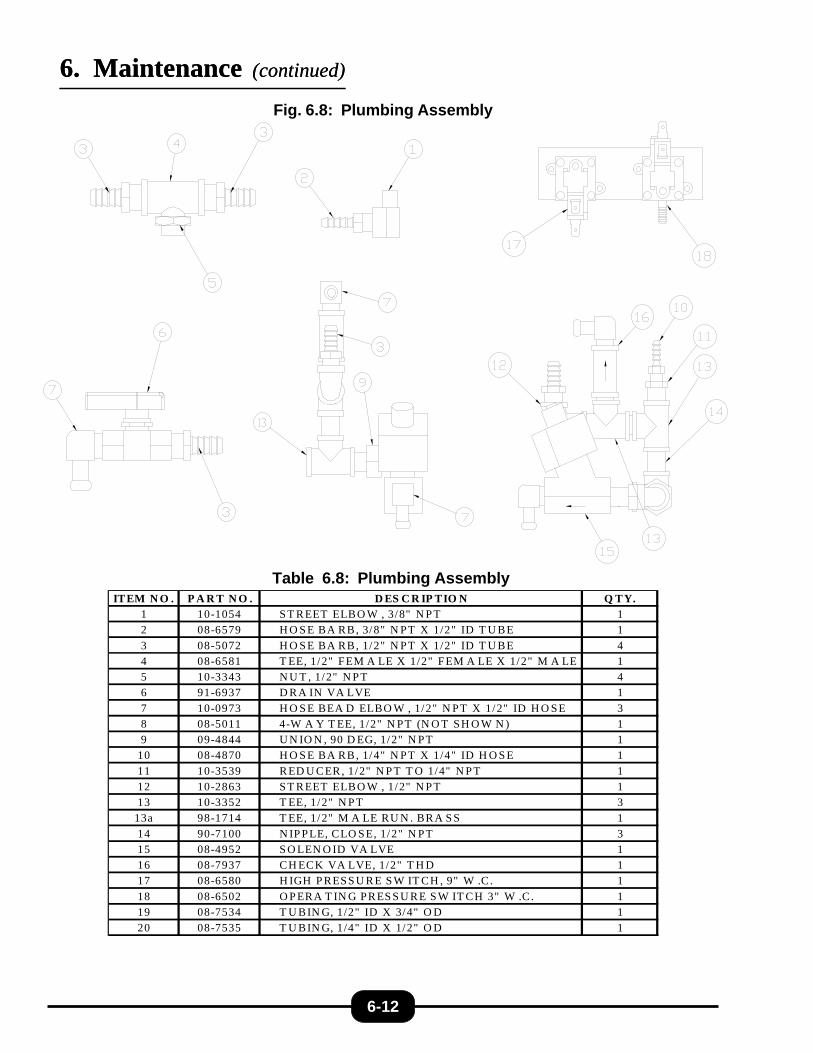
Fig. 6.8: Plumbing Assembly
6-12
ITEM N O . P A R T N O . D ES C R IP TIO N Q TY.1 10-1054 S T REET ELBO W , 3/8" N P T 12 08-6579 H O S E BA RB, 3/8" N PT X 1/2" ID T U BE 1
3 08-5072 H O S E BA RB, 1/2" N PT X 1/2" ID T U BE 44 08-6581 T EE, 1/2" FEM A LE X 1/2" FEM A LE X 1/2" M A LE 15 10-3343 N U T , 1/2" N P T 46 91-6937 D RA IN VA LVE 1
7 10-0973 H O S E BEA D ELBO W , 1/2" N PT X 1/2" ID H O SE 38 08-5011 4-W A Y T EE, 1/2" N PT (N O T SH O W N ) 19 09-4844 U N IO N , 90 D EG, 1/2" N PT 1
10 08-4870 H O S E BA RB, 1/4" N PT X 1/4" ID H O S E 1
11 10-3539 RED U CER, 1/2" N P T T O 1/4" N P T 112 10-2863 S T REET ELBO W , 1/2" N P T 113 10-3352 T EE, 1/2" N P T 3
13a 98-1714 T EE, 1/2" M A LE RU N . BRA S S 1
14 90-7100 N IP PLE, CLO SE, 1/2" N PT 315 08-4952 S O LEN O ID VA LVE 116 08-7937 CH ECK VA LVE, 1/2" T H D 117 08-6580 H IGH P RESS U RE S W IT CH , 9" W .C . 1
18 08-6502 O P ERA T IN G PRES S U RE S W IT CH 3" W .C . 119 08-7534 T U BIN G, 1/2" ID X 3/4" O D 120 08-7535 T U BIN G, 1/4" ID X 1/2" O D 1
6. Maintenance (continued)6. Maintenance (continued)
Table 6.8: Plumbing Assembly
6-13
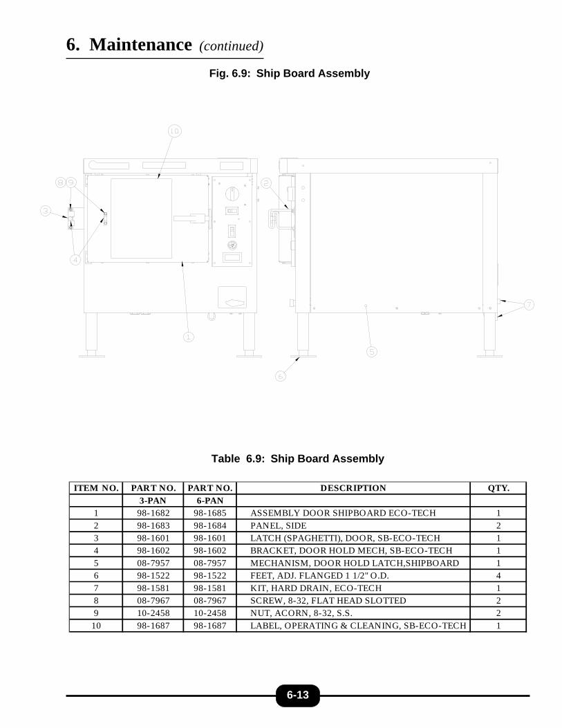
ITEM NO. PART NO. PART NO. DESCRIPTION QTY.3-PAN 6-PAN
1 98-1682 98-1685 ASSEMBLY DOOR SHIPBOARD ECO-TECH 12 98-1683 98-1684 PANEL, SIDE 23 98-1601 98-1601 LATCH (SPAGHETTI), DOOR, SB-ECO-TECH 14 98-1602 98-1602 BRACKET, DOOR HOLD MECH, SB-ECO-TECH 15 08-7957 08-7957 MECHANISM, DOOR HOLD LATCH,SHIPBOARD 16 98-1522 98-1522 FEET, ADJ. FLANGED 1 1/2" O.D. 47 98-1581 98-1581 KIT, HARD DRAIN, ECO-TECH 18 08-7967 08-7967 SCREW, 8-32, FLAT HEAD SLOTTED 29 10-2458 10-2458 NUT, ACORN, 8-32, S.S. 2
10 98-1687 98-1687 LABEL, OPERATING & CLEANING, SB-ECO-TECH 1
Table 6.9: Ship Board Assembly
Fig. 6.9: Ship Board Assembly
6. Maintenance (continued)