Embed Size (px)
Citation preview
– 2 –
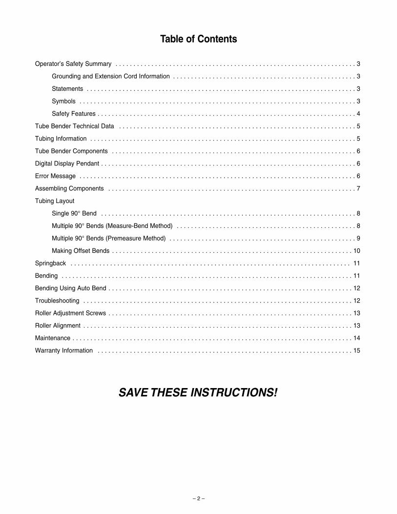
Table of Contents
Operator’s Safety Summary . . . . . . . . . . . . . . . . . . . . . . . . . . . . . . . . . . . . . . . . . . . . . . . . . . . . . . . . . . . . . . . . . . . 3
Grounding and Extension Cord Information . . . . . . . . . . . . . . . . . . . . . . . . . . . . . . . . . . . . . . . . . . . . . . . . . . . 3
Statements . . . . . . . . . . . . . . . . . . . . . . . . . . . . . . . . . . . . . . . . . . . . . . . . . . . . . . . . . . . . . . . . . . . . . . . . . . . 3
Symbols . . . . . . . . . . . . . . . . . . . . . . . . . . . . . . . . . . . . . . . . . . . . . . . . . . . . . . . . . . . . . . . . . . . . . . . . . . . . . 3
Safety Features . . . . . . . . . . . . . . . . . . . . . . . . . . . . . . . . . . . . . . . . . . . . . . . . . . . . . . . . . . . . . . . . . . . . . . . . 4
Tube Bender Technical Data . . . . . . . . . . . . . . . . . . . . . . . . . . . . . . . . . . . . . . . . . . . . . . . . . . . . . . . . . . . . . . . . . . 5
Tubing Information . . . . . . . . . . . . . . . . . . . . . . . . . . . . . . . . . . . . . . . . . . . . . . . . . . . . . . . . . . . . . . . . . . . . . . . . . . 5
Tube Bender Components . . . . . . . . . . . . . . . . . . . . . . . . . . . . . . . . . . . . . . . . . . . . . . . . . . . . . . . . . . . . . . . . . . . . 6
Digital Display Pendant . . . . . . . . . . . . . . . . . . . . . . . . . . . . . . . . . . . . . . . . . . . . . . . . . . . . . . . . . . . . . . . . . . . . . . . 6
Error Message . . . . . . . . . . . . . . . . . . . . . . . . . . . . . . . . . . . . . . . . . . . . . . . . . . . . . . . . . . . . . . . . . . . . . . . . . . . . . 6
Assembling Components . . . . . . . . . . . . . . . . . . . . . . . . . . . . . . . . . . . . . . . . . . . . . . . . . . . . . . . . . . . . . . . . . . . . . 7
Tubing Layout
Single 90° Bend . . . . . . . . . . . . . . . . . . . . . . . . . . . . . . . . . . . . . . . . . . . . . . . . . . . . . . . . . . . . . . . . . . . . . . . 8
Multiple 90° Bends (Measure-Bend Method) . . . . . . . . . . . . . . . . . . . . . . . . . . . . . . . . . . . . . . . . . . . . . . . . . . 8
Multiple 90° Bends (Premeasure Method) . . . . . . . . . . . . . . . . . . . . . . . . . . . . . . . . . . . . . . . . . . . . . . . . . . . . 9
Making Offset Bends . . . . . . . . . . . . . . . . . . . . . . . . . . . . . . . . . . . . . . . . . . . . . . . . . . . . . . . . . . . . . . . . . . . 10
Springback . . . . . . . . . . . . . . . . . . . . . . . . . . . . . . . . . . . . . . . . . . . . . . . . . . . . . . . . . . . . . . . . . . . . . . . . . . . . . . 11
Bending . . . . . . . . . . . . . . . . . . . . . . . . . . . . . . . . . . . . . . . . . . . . . . . . . . . . . . . . . . . . . . . . . . . . . . . . . . . . . . . . . 11
Bending Using Auto Bend . . . . . . . . . . . . . . . . . . . . . . . . . . . . . . . . . . . . . . . . . . . . . . . . . . . . . . . . . . . . . . . . . . . . 12
Troubleshooting . . . . . . . . . . . . . . . . . . . . . . . . . . . . . . . . . . . . . . . . . . . . . . . . . . . . . . . . . . . . . . . . . . . . . . . . . . . 12
Roller Adjustment Screws . . . . . . . . . . . . . . . . . . . . . . . . . . . . . . . . . . . . . . . . . . . . . . . . . . . . . . . . . . . . . . . . . . . . 13
Roller Alignment . . . . . . . . . . . . . . . . . . . . . . . . . . . . . . . . . . . . . . . . . . . . . . . . . . . . . . . . . . . . . . . . . . . . . . . . . . . 13
Maintenance . . . . . . . . . . . . . . . . . . . . . . . . . . . . . . . . . . . . . . . . . . . . . . . . . . . . . . . . . . . . . . . . . . . . . . . . . . . . . . 14
Warranty Information . . . . . . . . . . . . . . . . . . . . . . . . . . . . . . . . . . . . . . . . . . . . . . . . . . . . . . . . . . . . . . . . . . . . . . . 15
SAVE THESE INSTRUCTIONS!
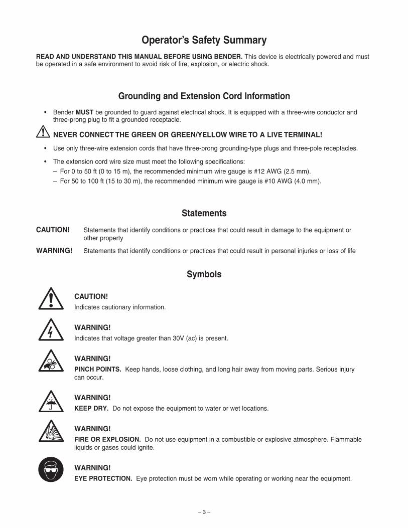
Operator’s Safety SummaryREAD AND UNDERSTAND THIS MANUAL BEFORE USING BENDER. This device is electrically powered and mustbe operated in a safe environment to avoid risk of fire, explosion, or electric shock.
Grounding and Extension Cord Information
• Bender MUST be grounded to guard against electrical shock. It is equipped with a three-wire conductor and three-prong plug to fit a grounded receptacle.
NEVER CONNECT THE GREEN OR GREEN/YELLOW WIRE TO A LIVE TERMINAL!
• Use only three-wire extension cords that have three-prong grounding-type plugs and three-pole receptacles.
• The extension cord wire size must meet the following specifications:
– For 0 to 50 ft (0 to 15 m), the recommended minimum wire gauge is #12 AWG (2.5 mm).
– For 50 to 100 ft (15 to 30 m), the recommended minimum wire gauge is #10 AWG (4.0 mm).
Statements
CAUTION! Statements that identify conditions or practices that could result in damage to the equipment or other property
WARNING! Statements that identify conditions or practices that could result in personal injuries or loss of life
CAUTION! Indicates cautionary information.
WARNING!Indicates that voltage greater than 30V (ac) is present.
WARNING!PINCH POINTS. Keep hands, loose clothing, and long hair away from moving parts. Serious injury can occur.
WARNING!KEEP DRY. Do not expose the equipment to water or wet locations.
WARNING!FIRE OR EXPLOSION. Do not use equipment in a combustible or explosive atmosphere. Flammableliquids or gases could ignite.
WARNING!EYE PROTECTION. Eye protection must be worn while operating or working near the equipment.
– 3 –
!
Symbols
44
l
!-
G
~
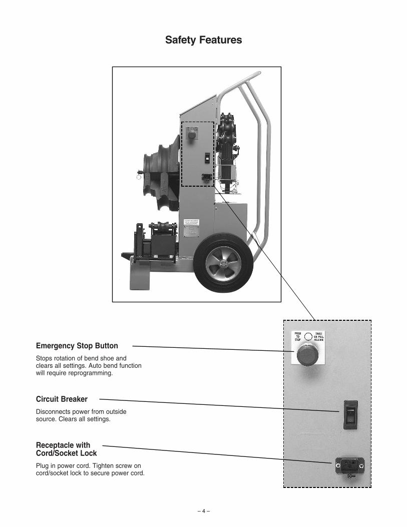
Emergency Stop Button
Stops rotation of bend shoe andclears all settings. Auto bend function will require reprogramming.
Circuit Breaker
Disconnects power from outside source. Clears all settings.
Receptacle with Cord/Socket Lock
Plug in power cord. Tighten screw on cord/socket lock to secure power cord.
Safety Features
– 4 –
– 5 –
Tube Bender Technical DataBENDING RANGE: 1° to 110°, in 1° increments. Bending in excess of 110° may damage bender.
DIMENSIONS: Vertical Position: 44 in. (112 cm) high, 29 in. (74 cm) wide, 30 in. (76 cm) deep
WEIGHT: 420 lb (191 kg)
POWER REQUIREMENTS: MS-TBE-1 MS-TBE-2115 V (ac) 50/60 Hz 230 V (ac) 50/60 HzMaximum current: 13 A Maximum current: 7 A
Tubing Information
• All tubing should be free of scratches and suitable for bending.
• Bends 1, 1 1/4, 1 1/2, and 2 in.; 25, 32, 38, and 50 mm OD tubing in a variety of wall thicknesses.
• Carbon steel tubing should be soft (annealed), seamless (ASTM A179), or welded and drawn, DIN 2391-1 andDIN 2391-2 or equivalent, with a hardness of 72 HRB, HV (VPN) 130 or less.
• Stainless steel tubing should be fully annealed, seamless, or welded and drawn, meeting ASTM A269, ASTM A213, EN ISO 1127, or equivalent specification, with a hardness of 90 HRB, HV (VPN) 180 or less.
• The following information for bending annealed tubing is listed below in Table 1: bend radius, wall thickness limits,and minimum straight length required to make a 90° bend using the tail roller.
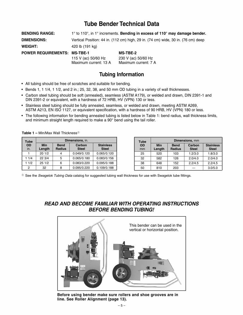
This bender can be used in thevertical or horizontal position.
Before using bender make sure rollers and shoe grooves are inline. See Roller Alignment (page 13).
READ AND BECOME FAMILIAR WITH OPERATING INSTRUCTIONS BEFORE BENDING TUBING!
TubeODin.
MinLength
BendRadius
CarbonSteel
StainlessSteel
1 20 1/2 4 0.049/0.120 0.065/0.120
1 1/4
1 1/2
2
22 3/4
25 1/2
32
5
6
8
0.095/0.188
0.065/0.180
0.083/0.220
0.095/0.220
0.083/0.156
0.109/0.188
TubeODmm
MinLength
BendRadius
CarbonSteel
StainlessSteel
25 520 103 1.2/3.0 1.8/3.0
32
38
50
582
648
810
126
152
203
2.2/4.5
2.0/4.0
2.2/4.5
—
2.0/4.0
3.0/5.0
Dimensions, in. Dimensions, mm
Table 1 – Min/Max Wall Thickness➀
➀ See the Swagelok Tubing Data catalog for suggested tubing wall thickness for use with Swagelok tube fittings.
– 6 –
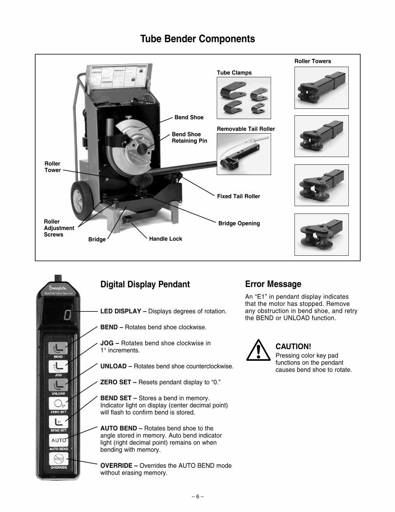
CAUTION!Pressing color key padfunctions on the pendantcauses bend shoe to rotate.
Error MessageAn “E1” in pendant display indicatesthat the motor has stopped. Removeany obstruction in bend shoe, and retry the BEND or UNLOAD function.
Digital Display Pendant
LED DISPLAY – Displays degrees of rotation.
BEND – Rotates bend shoe clockwise.
JOG – Rotates bend shoe clockwise in1° increments.
UNLOAD – Rotates bend shoe counterclockwise.
ZERO SET – Resets pendant display to “0.”
BEND SET – Stores a bend in memory. Indicator light on display (center decimal point) will flash to confirm bend is stored.
AUTO BEND – Rotates bend shoe to the angle stored in memory. Auto bend indicator light (right decimal point) remains on whenbending with memory.
OVERRIDE – Overrides the AUTO BEND modewithout erasing memory.
!
Roller Towers
Tube Clamps
Removable Tail Roller
Fixed Tail Roller
Bend Shoe
Bridge Opening
Handle Lock
Roller AdjustmentScrews
Bend ShoeRetaining Pin
Bridge
Roller Tower
Tube Bender Components
– 7 –
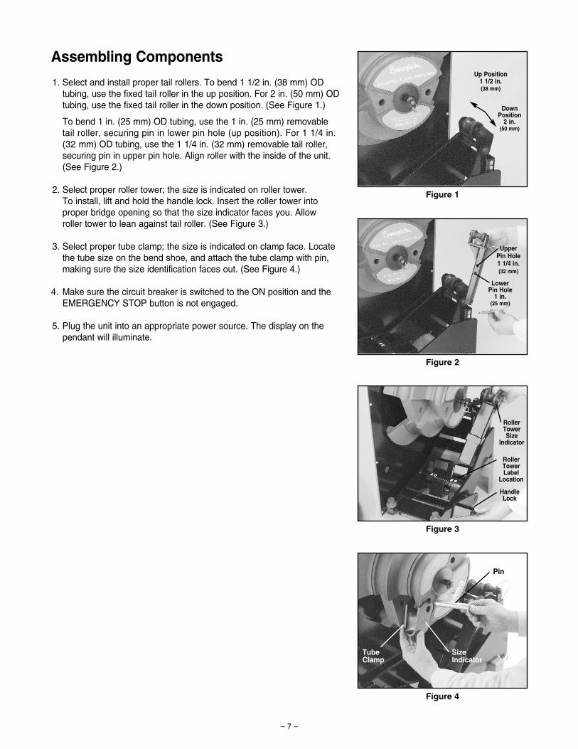
Assembling Components
1. Select and install proper tail rollers. To bend 1 1/2 in. (38 mm) ODtubing, use the fixed tail roller in the up position. For 2 in. (50 mm) ODtubing, use the fixed tail roller in the down position. (See Figure 1.)
To bend 1 in. (25 mm) OD tubing, use the 1 in. (25 mm) removabletail roller, securing pin in lower pin hole (up position). For 1 1/4 in.(32 mm) OD tubing, use the 1 1/4 in. (32 mm) removable tail roller,securing pin in upper pin hole. Align roller with the inside of the unit.(See Figure 2.)
2. Select proper roller tower; the size is indicated on roller tower. To install, lift and hold the handle lock. Insert the roller tower intoproper bridge opening so that the size indicator faces you. Allow roller tower to lean against tail roller. (See Figure 3.)
3. Select proper tube clamp; the size is indicated on clamp face. Locatethe tube size on the bend shoe, and attach the tube clamp with pin,making sure the size identification faces out. (See Figure 4.)
4. Make sure the circuit breaker is switched to the ON position and theEMERGENCY STOP button is not engaged.
5. Plug the unit into an appropriate power source. The display on thependant will illuminate.
Figure 1
Figure 2
Figure 3
Figure 4
Roller TowerSize
Indicator
Roller TowerLabel
Location
Handle Lock
Pin
Upper Pin Hole 1 1/4 in.(32 mm)
Up Position1 1/2 in.(38 mm)
DownPosition
2 in.(50 mm)
LowerPin Hole
1 in.(25 mm)
TubeClamp
SizeIndicator
CenterLine
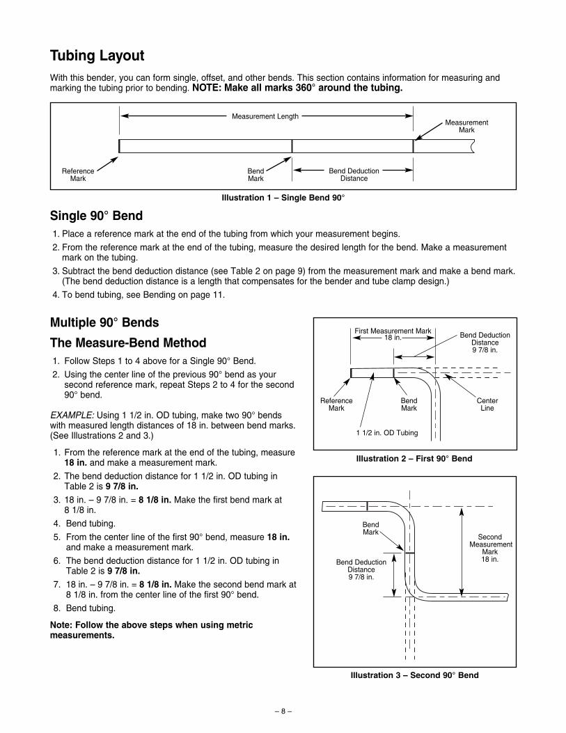
Tubing LayoutWith this bender, you can form single, offset, and other bends. This section contains information for measuring andmarking the tubing prior to bending. NOTE: Make all marks 360° around the tubing.
Single 90° Bend1. Place a reference mark at the end of the tubing from which your measurement begins.
2. From the reference mark at the end of the tubing, measure the desired length for the bend. Make a measurementmark on the tubing.
3. Subtract the bend deduction distance (see Table 2 on page 9) from the measurement mark and make a bend mark.(The bend deduction distance is a length that compensates for the bender and tube clamp design.)
4. To bend tubing, see Bending on page 11.
MeasurementMark
Measurement Length
Reference Mark
Bend DeductionDistance
Bend Mark
First Measurement Mark18 in.
SecondMeasurement
Mark18 in.
Bend DeductionDistance9 7/8 in.
Bend DeductionDistance9 7/8 in.
ReferenceMark
BendMark
BendMark
1 1/2 in. OD Tubing
Multiple 90° Bends
The Measure-Bend Method1. Follow Steps 1 to 4 above for a Single 90° Bend.
2. Using the center line of the previous 90° bend as yoursecond reference mark, repeat Steps 2 to 4 for the second90° bend.
EXAMPLE: Using 1 1/2 in. OD tubing, make two 90° bendswith measured length distances of 18 in. between bend marks.(See Illustrations 2 and 3.)
1. From the reference mark at the end of the tubing, measure18 in. and make a measurement mark.
2. The bend deduction distance for 1 1/2 in. OD tubing inTable 2 is 9 7/8 in.
3. 18 in. – 9 7/8 in. = 8 1/8 in. Make the first bend mark at8 1/8 in.
4. Bend tubing.
5. From the center line of the first 90° bend, measure 18 in.and make a measurement mark.
6. The bend deduction distance for 1 1/2 in. OD tubing inTable 2 is 9 7/8 in.
7. 18 in. – 9 7/8 in. = 8 1/8 in. Make the second bend mark at8 1/8 in. from the center line of the first 90° bend.
8. Bend tubing.
Note: Follow the above steps when using metricmeasurements.
Illustration 1 – Single Bend 90°
Illustration 2 – First 90° Bend
Illustration 3 – Second 90° Bend
– 8 –
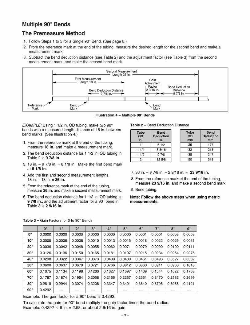
Multiple 90° Bends
The Premeasure Method1. Follow Steps 1 to 3 for a Single 90° Bend. (See page 8.)2. From the reference mark at the end of the tubing, measure the desired length for the second bend and make a
measurement mark.3. Subtract the bend deduction distance (see Table 2) and the adjustment factor (see Table 3) from the second
measurement mark, and make the second bend mark.
– 9 –
First MeasurementLength 18 in.
Bend Deduction Distance9 7/8 in.
Gain Adjustment
Factor2 9/16 in.
ReferenceMark
BendMark
BendMark
Second MeasurementLength 36 in.
Bend DeductionDistance9 7/8 in.
Illustration 4 – Multiple 90° Bends
EXAMPLE: Using 1 1/2 in. OD tubing, make two 90°bends with a measured length distance of 18 in. betweenbend marks. (See Illustration 4.)
1. From the reference mark at the end of the tubing,measure 18 in. and make a measurement mark.
2. The bend deduction distance for 1 1/2 in. OD tubing inTable 2 is 9 7/8 in.
3. 18 in. – 9 7/8 in. = 8 1/8 in. Make the first bend markat 8 1/8 in.
4. Add the first and second measurement lengths. 18 in. + 18 in. = 36 in.
5. From the reference mark at the end of the tubing,measure 36 in. and make a second measurement mark.
6. The bend deduction distance for 1 1/2 in. OD tubing is9 7/8 in., and the adjustment factor for a 90° bend inTable 3 is 2 9/16 in.
BendDeduction
in.
6 1/2
TubeODin.
1
1 1/4
1 1/2
2
8 3/16
9 7/8
12 5/8
BendDeduction
mm
177
TubeODmm
25
32
38
50
213
247
318
Table 2 – Bend Deduction Distance
0° 1°
0°
10°
20°
30°
40°
50°
0.0000
0.0005
0.0036
0.0126
0.0298
0.0600
0.0000
0.0006
0.0042
0.0136
0.0322
0.0637
Table 3 – Gain Factors for 0 to 90° Bends
60°
70°
80°
90°
0.1075
0.1787
0.2819
0.4292
0.1134
0.1874
0.2944
—
2° 3° 4°
0.0000 0.0000 0.0000
0.0008
0.0048
0.0150
0.0347
0.0679
0.1196
0.1964
0.3074 0.3208
0.2058
0.1260
0.0721
0.0373
0.0165
0.0055
0.0010 0.0013
0.0062
0.0181
0.0400
0.0766
0.1327
0.2156
0.3347
5° 6° 7°
0.0197
0.0000
8° 9°
0.0001 0.0001 0.0003
0.0031
0.0003
0.0026
0.0100
0.0254
0.0527
0.0963
0.1622
0.2582
0.3955 0.4121
0.1703
0.1018
0.0562
0.0276
0.0111
0.26990.24700.23610.2257
0.1397 0.15440.1469
0.0860
0.0461
0.0215
0.0079
0.0018 0.0022
0.0090
0.0234
0.0493
0.0911
0.37950.36400.3491
0.0812
0.0430
0.0071
0.0015
— — — — — — — —
Example: The gain factor for a 90° bend is 0.4292.
To calculate the gain for 90° bend multiply the gain factor times the bend radius.Example: 0.4292 � 6 in. = 2.58, or about 2 9/16 in. gain
7. 36 in. – 9 7/8 in. – 2 9/16 in. = 23 9/16 in.
8. From the reference mark at the end of the tubing,measure 23 9/16 in. and make a second bend mark.
9. Bend tubing.
Note: Follow the above steps when using metricmeasurements.
– 10 –
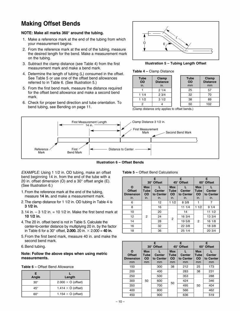
Making Offset BendsNOTE: Make all marks 360° around the tubing.
1. Make a reference mark at the end of the tubing from whichyour measurement begins.
2. From the reference mark at the end of the tubing, measurethe desired length for the bend. Make a measurement markon the tubing.
3. Subtract the clamp distance (see Table 4) from the firstmeasurement mark and make a bend mark.
4. Determine the length of tubing (L) consumed in the offset.See Table 5 or use one of the offset bend allowances referred to in Table 6. (See Illustration 5.)
5. From the first bend mark, measure the distance requiredfor the offset bend allowance and make a second bendmark.
6. Check for proper bend direction and tube orientation. Tobend tubing, see Bending on page 11.
L
O E
First Measurement Length14 in.
Clamp Distance 3 1/2 in.
First Measurement Mark Second Bend Mark
Distance to CenterFirstBend Mark
ReferenceMark
(Clamp distance only applies to offset bends.)
Illustration 5 – Tubing Length Offset
Illustration 6 – Offset Bends
EXAMPLE: Using 1 1/2 in. OD tubing, make an offsetbend beginning 14 in. from the end of the tube with a20 in. offset dimension (O) and a 30° offset angle (E).(See Illustration 6.)
1.From the reference mark at the end of the tubing,measure 14 in. and make a measurement mark.
2.The clamp distance for 1 1/2 in. OD tubing in Table 4 is3 1/2 in.
3.14 in. – 3 1/2 in. = 10 1/2 in. Make the first bend mark at10 1/2 in.
4.The 20 in. offset bend is not in Table 5. Calculate thecenter-to-center distance by multiplying 20 in. by the factorin Table 6 for a 30° offset, 2.000. 20 in. � 2.000 = 40 in.
5.From the first bend mark, measure 40 in. and make thesecond bend mark.
6.Bend tubing.
Note: Follow the above steps when using metricmeasurements.
EAngle
LLength
30°
45°
60°
2.000 � O (offset)
1.414 � O (offset)
1.154 � O (offset)
ClampDistance
in.
2 1/4
TubeODin.
1
1 1/4
1 1/2
2
2 3/4
3 1/2
4
ClampDistance
mm
57
TubeODmm
25
32
38
50
70
89
102
OOffset
Dimensionin.
MaxTubeODin.
LCenter
to Centerin.
MaxTubeODin.
LCenter
to Centerin.
MaxTubeODin.
LCenter
to Centerin.
E30° Offset
E45° Offset
E60° Offset
6
8
10
12
14
16
18
2
12
16
20
24
28
32
36
1 1/2
2
8 3/8
11 1/4
14
16 3/4
19 5/8
22 3/8
25 1/4
1
1 1/2
2
7
9 1/4
11 1/2
13 3/4
16 1/8
18 3/8
20 3/4
OOffset
Dimensionmm
MaxTubeODmm
LCenter
to Centermm
MaxTubeODmm
LCenter
to Centermm
MaxTubeODmm
LCenter
to Centermm
E30° Offset
E45° Offset
E60° Offset
150
200
250
300
350
400
450
50
300
400
500
600
700
800
900
38
50
212
283
353
424
495
566
636
25
38
50
173
231
288
346
404
462
519
Table 4 – Clamp Distance
Table 5 – Offset Bend Calculations
Table 6 – Offset Bend Allowance
– 11 –
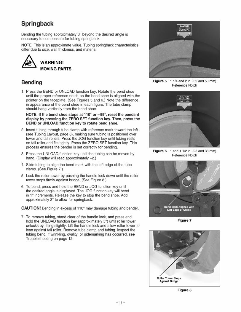
Springback
Bending the tubing approximately 3° beyond the desired angle isnecessary to compensate for tubing springback.
NOTE: This is an approximate value. Tubing springback characteristicsdiffer due to size, wall thickness, and material.
Bending
1. Press the BEND or UNLOAD function key. Rotate the bend shoeuntil the proper reference notch on the bend shoe is aligned with thepointer on the faceplate. (See Figures 5 and 6.) Note the differencein appearance of the bend shoe in each figure. The tube clampshould hang vertically from the bend shoe.
NOTE: If the bend shoe stops at 110° or – 99°, reset the pendantdisplay by pressing the ZERO SET function key. Then, press theBEND or UNLOAD function key to rotate bend shoe.
2. Insert tubing through tube clamp with reference mark toward the left(see Tubing Layout, page 8), making sure tubing is positioned overtower and tail rollers. Press the JOG function key until tubing rests on tail roller and fits tightly. Press the ZERO SET function key. Thisprocess ensures the bender is set correctly for bending.
3. Press the UNLOAD function key until the tubing can be moved byhand. (Display will read approximately –2.)
4. Slide tubing to align the bend mark with the left edge of the tubeclamp. (See Figure 7.)
5. Lock the roller tower by pushing the handle lock down until the rollertower stops firmly against bridge. (See Figure 8.)
6. To bend, press and hold the BEND or JOG function key until the desired angle is displayed. The JOG function key will bend in 1° increments. Release the key to stop the bend shoe. Add approximately 3° to allow for springback.
CAUTION! Bending in excess of 110° may damage tubing and bender.
7. To remove tubing, stand clear of the handle lock, and press and hold the UNLOAD function key (approximately 5°) until roller towerunlocks by lifting slightly. Lift the handle lock and allow roller tower tolean against tail roller. Remove tube clamp and tubing. Inspect thetubing bend; if wrinkling, ovality, or sidemarking has occurred, seeTroubleshooting on page 12.
Figure 5 1 1/4 and 2 in. (32 and 50 mm)Reference Notch
Figure 6 1 and 1 1/2 in. (25 and 38 mm)Reference Notch
Bend Mark Aligned withLeft Edge of Clamp
Roller Tower Stops Against Bridge
Figure 7
Figure 8
WARNING!MOVING PARTS.
4~
– 12 –
Bending Using Auto BendUse the auto bend feature to program a bend angle into the bender’smemory for applications where a single bend angle must be repeated.
NOTE: A bend setting will be stored in memory until power is disconnected or a new bend is set.
1. Follow steps 1–3 under Bending (see page 11), then slide tubingcompletely away from tube clamp and bend shoe.
2. Press the BEND or JOG function key until the desired angle isdisplayed. Add approximately 3° to allow for springback. Press the BEND SET function key to store the bend angle. The BENDSET light (center decimal point) on the display pendant will flash momentarily. Press the UNLOAD function key until the display readsapproximately –2.
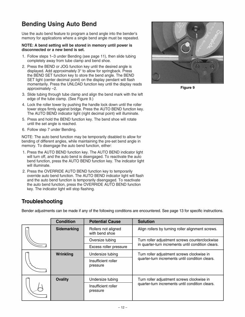
3. Slide tubing through tube clamp and align the bend mark with the leftedge of the tube clamp. (See Figure 9.)
4. Lock the roller tower by pushing the handle lock down until the rollertower stops firmly against bridge. Press the AUTO BEND function key.The AUTO BEND indicator light (right decimal point) will illuminate.
5. Press and hold the BEND function key. The bend shoe will rotateuntil the set angle is reached.
6. Follow step 7 under Bending.
NOTE: The auto bend function may be temporarily disabled to allow forbending of different angles, while maintaining the pre-set bend angle inmemory. To disengage the auto bend function, either:
1. Press the AUTO BEND function key. The AUTO BEND indicator lightwill turn off, and the auto bend is disengaged. To reactivate the autobend function, press the AUTO BEND function key. The indicator lightwill illuminate.
2. Press the OVERRIDE AUTO BEND function key to temporarilyoverride auto bend function. The AUTO BEND indicator light will flashand the auto bend function is temporarily disengaged. To reactivatethe auto bend function, press the OVERRIDE AUTO BEND functionkey. The indicator light will stop flashing.
Figure 9
Troubleshooting
Bender adjustments can be made if any of the following conditions are encountered. See page 13 for specific instructions.
Sidemarking
Ovality
Wrinkling
Rollers not aligned with bend shoe
Oversize tubing
Excess roller pressure
Undersize tubing
Insufficient roller pressure
Undersize tubing
Insufficient roller pressure
Align rollers by turning roller alignment screws.
Turn roller adjustment screws counterclockwise in quarter-turn increments until condition clears.
Turn roller adjustment screws clockwise inquarter-turn increments until condition clears.
Turn roller adjustment screws clockwise inquarter-turn increments until condition clears.
Condition Potential Cause Solution
Roller AlignmentThe two roller alignment screws, located on the rear side plate of the bridge assembly (see Figure 11), allow adjustmentof the bridge assembly to keep the roller towers and bend shoe aligned. Misalignment can lead to sidemarking.
To Check Alignment:
• Viewing the bender from the side, look between the roller towers and the bend shoe. If the roller tower appears to be misaligned withthe bend shoe, loosen the lock nuts on the roller alignment screwswith a 9/16 in. wrench.
• Using a 3/16 in. hex key, turn the roller alignment screws until theroller tower aligns with the bend shoe. Tighten the lock nuts.
• Always set the roller alignment screws evenly to keep the bridgeassembly parallel with the bend shoe.
Figure 11
– 13 –
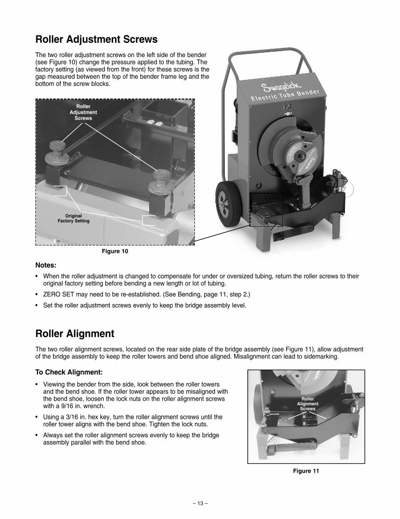
Roller Adjustment ScrewsThe two roller adjustment screws on the left side of the bender (see Figure 10) change the pressure applied to the tubing. The factory setting (as viewed from the front) for these screws is the gap measured between the top of the bender frame leg and thebottom of the screw blocks.
Notes:
• When the roller adjustment is changed to compensate for under or oversized tubing, return the roller screws to theiroriginal factory setting before bending a new length or lot of tubing.
• ZERO SET may need to be re-established. (See Bending, page 11, step 2.)
• Set the roller adjustment screws evenly to keep the bridge assembly level.
Figure 10
RollerAdjustment
Screws
OriginalFactory Setting
RollerAlignment
Screws
MaintenanceIf this bender is subjected to flooding, severe impact, fire, or otherextreme conditions, it should be inspected thoroughly by a trainedtechnician before use.
Front ChainThe front chain requires no routine adjustment. However, it will stretchslightly after making the first 10 to 20 bends of 1 1/2 or 2 in.; or 38 or50 mm OD heavy wall tubing. If there is any slack in the chain:
1. Disconnect the bender from the power source and remove the roller tower.
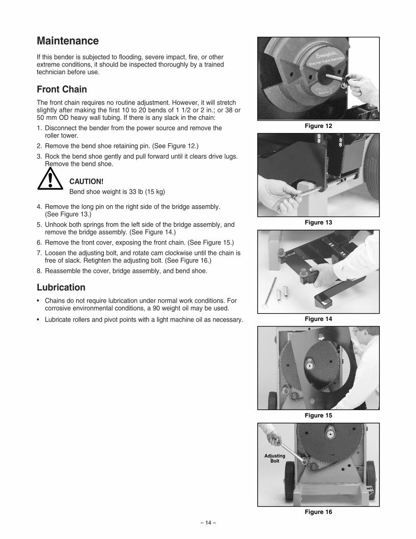
2. Remove the bend shoe retaining pin. (See Figure 12.)
3. Rock the bend shoe gently and pull forward until it clears drive lugs.Remove the bend shoe.
CAUTION!Bend shoe weight is 33 lb (15 kg)
4. Remove the long pin on the right side of the bridge assembly. (See Figure 13.)
5. Unhook both springs from the left side of the bridge assembly, andremove the bridge assembly. (See Figure 14.)
6. Remove the front cover, exposing the front chain. (See Figure 15.)
7. Loosen the adjusting bolt, and rotate cam clockwise until the chain isfree of slack. Retighten the adjusting bolt. (See Figure 16.)
8. Reassemble the cover, bridge assembly, and bend shoe.
Lubrication• Chains do not require lubrication under normal work conditions. For
corrosive environmental conditions, a 90 weight oil may be used.
• Lubricate rollers and pivot points with a light machine oil as necessary.
– 14 –
Figure 12
Figure 13
Figure 14
Figure 15
Figure 16
Adjusting Bolt
!

THE SWAGELOK LIMITED LIFETIME WARRANTY
Swagelok hereby warrants to the purchaser of this Product that the non-electrical components of the Product shall be freefrom defects in material and workmanship for the life of the Product. All electrical components installed in or on theProduct are warranted to be free from defects in material and workmanship for twelve months from the date of purchase.
The purchaser’s remedies shall be limited to replacement and installation of any parts that fail through a defect in materialor workmanship.
MANUFACTURER SPECIFICALLY DISAVOWS ANY OTHER REPRESENTATION, EXPRESS OR IMPLIED,WARRANTY, OR LIABILITY RELATING TO THE CONDITION OF USE OF THE PRODUCT, AND IN NO EVENTSHALL SWAGELOK BE LIABLE TO PURCHASER, OR ANY THIRD PARTY, FOR ANY DIRECT OR INDIRECTCONSEQUENTIAL OR INCIDENTAL DAMAGES.
SWAGELOK COMPANY29500 Solon Road. Solon, Ohio 44139-3492 U.S.A.Telephone: 1-440-248-4600 FAX: 1-440-349-5970
– 15 –

Swagelok—TM Swagelok Company©1999, 2002, 2004 Swagelok CompanyPrinted in U.S.A.October 2004, R4MS-13-138