Embed Size (px)
Citation preview
International Journal of Advances in Engineering Research http://www.ijaer.com
(IJAER) 2015, Vol. No. 10, Issue No. VI, December e-ISSN: 2231-5152/ p-ISSN: 2454-1796
1
INTERNATIONAL JOURNAL OF ADVANCES IN ENGINEERING RESEARCH
ELECTRIC VEHICLE PROPULSION SYSTEM
* Karim N. Mobariz, ** Ahmed M. Youssef,
*** Mohamed Abdel-Rahman
* Ph.D. Candidate,
Ain Shams University, Cairo, Egypt
** Associate Professor,
Egyptian Armed Forces, Cairo, Egypt
*** Associate Professor, Electrical Power Engineering,
Ain Shams University, Cairo, Egypt
ABSTRACT
Global pollution and radiations due to greenhouse gases are of serious concern in densely populated
urban areas. Electric vehicles are considered one of the pillars of eco-friendly solutions since they produce
no exhaust gases. Therefore this paper carries out the study and the improvement in overall performance of
an electric vehicle propulsion system, which consists of electric energy supply and traction systems. The
supply system constitutes the fuel-cell stack and the DC-DC buck converter, while the traction system
constitutes the Brushless Direct Current (BLDC) motor, its voltage source inverter and drive system.
Keywords: buck converter; fuel cell; BLDC; fuzzy logic controller; speed control; current control
INTRODUCTION
Fossil-fuel pollutants being pumped into the atmosphere and greenhouse gas emissions are
estimated to be responsible for around 1.3 million deaths every year. The environmental impact of
combustion of gasoline and other fossil fuels has renewed the researchers to focus on electric
vehicles. Mass adoption of electric vehicles would lead to substantial reductions in greenhouse gas
emissions, according to a study from Newcastle University and reports from the Electric Power
Research Institute (EPRI) and the Natural Resources Defense Council (NRDC) [1, 2].
Electric vehicle propulsion system consists of electric energy supply and traction systems.
Although batteries are probably the most widely used energy storage devices [3], they are not
universal solutions for powering electric vehicles due to inherent limitations in recharging time and
lifetime. Considering the role of hydrogen in our future society, clean fuel cell technology is an
attractive alternative since fuel cells emit essentially no pollutants and have high-power density and
quick start. Unfortunately, fuel cells are sensitive to sudden changes in the loads; i.e. when the load
increases, the fuel cell stacks voltage will drop steeply, which will affect the output voltage.
Therefore, a DC-DC buck converter is proposed to maintain the fuel cell stacks output voltage to a
desired value. An optimized proportional-integral-derivative (PID) controller is suggested for the
International Journal of Advances in Engineering Research http://www.ijaer.com
(IJAER) 2015, Vol. No. 10, Issue No. VI, December e-ISSN: 2231-5152/ p-ISSN: 2454-1796
2
INTERNATIONAL JOURNAL OF ADVANCES IN ENGINEERING RESEARCH
DC-DC buck converter to ensure a constant output voltage and to reject the disturbance from load
and fuel cells stacks. Hence, a fuel cell stack, a DC-DC buck converter and its associated controller
will constitute the electric energy supply system.
Electric motors play significant role in electric vehicles. Mainly, there are two types of DC motors
used in industry. The first one is the conventional DC motor where the flux is produced by the
current through the field coil of the stationary pole structure. The second type is the BLDC motor
where the permanent magnet provides the necessary air gap flux instead of the wire-wound field
poles [4]. Unlike conventional DC motor which uses mechanical commutator and brushes, BLDC
motor uses electronic commutation system which consists of an inverter and a position sensor that
detects rotor position for proper commutation of current. According to this structure, brush
maintenance free operation is achieved, and problems resulting from mechanical wear of brushes
and commutators are improved by changing the position of rotor and stator in DC motor. Therefore
BLDC motors have gained many advantages over conventional DC motors such as higher
reliability and efficiency, compactness, longer operating life, higher dynamic response, better speed
versus torque characteristics, noiseless operation, and higher torque-to-weight ratio. Due to these
advantages, BLDC motors are preferred for the electric vehicle application as traction motors, and
hence the electric vehicle traction system is constituted of the BLDC traction motor together with
voltage source inverter.
High performance electric motor drive systems are central to modern electric vehicle propulsion
systems [5]. The benefits accruing from the application of such drives are precision control of
torque, speed and position which promote superior electric vehicle dynamical performance [6].
Designing and controlling of a BLDC motor drive system requires an accurate model of the motor,
therefore modeling of a BLDC motor with a trapezoidal back-Electro Magnetic Force (back-EMF)
waveform shape along with a control system for its speed and current is presented. A fuzzy logic
controller is used for designing the speed control system due to its robustness to plant parameter
changes and to its better noise rejection capabilities, while an optimized PI controller is used for
designing the current control system.
The paper is organized in six sections: Section 2 describes briefly the components of the electric
vehicle propulsion system. Section 3explains the principle of operation of the traction system
components. Designing the controllers of the BLDC motor drive is detailed and simulation results
are explained in Section 4.Section 5 details the operational characteristics and the mathematical
modeling of the supply system components, followed by the design of the buck converter controller
and its simulation results. Finally, the paper concludes with a brief summary in Section 6.
ELECTRIC VEHICLE PROPULSION SYSTEM DESCRIPTION
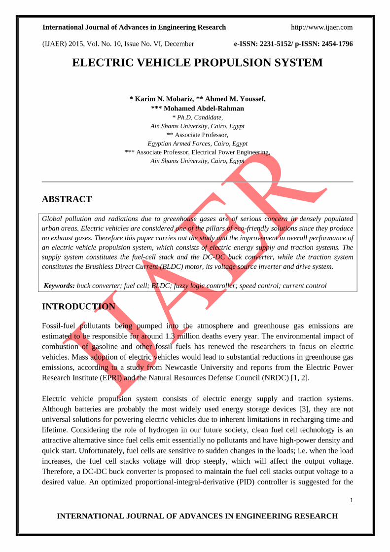
Fig. 1 shows the proposed electric vehicle propulsion system. It consists of electric energy supply
and traction systems. The supply system constitutes the fuel-cell stack and the DC-DC buck
International Journal of Advances in Engineering Research http://www.ijaer.com
(IJAER) 2015, Vol. No. 10, Issue No. VI, December e-ISSN: 2231-5152/ p-ISSN: 2454-1796
3
INTERNATIONAL JOURNAL OF ADVANCES IN ENGINEERING RESEARCH
converter, while the traction system constitutes the BLDC motor, its voltage source inverter and
drive system.
Figure 1 Electric vehicle propulsion system
TRACTION SYSTEM COMPONENTS
Complete electric vehicle traction system usually consists of BLDC motor, inverter bridge, rotor
position sensor, controller and driver circuit. A BLDC motor is synchronous motor with permanent
magnets on the rotor and armature windings on the stator. It is powered by a DC electric source via
an integrated inverter/switching power supply, which produces an AC electric signal to drive the
motor, i.e. the motor accomplishes commutation electronically. The commutation instants are
determined by the rotor position. Detecting the rotor position in BLDC motors is performed either
by position sensors like Hall sensor, position encoder and resolver etc. or by sensorless techniques.
A three-phase BLDC motor has three stator windings, which are oriented 120o apart. When the
motor rotates, each winding generates a voltage called back-EMF, which has an opposite polarity
to the energized voltage. There are two types of stator windings: trapezoidal and sinusoidal, which
refers to the shape of the back-EMF signal. Trapezoidal motor is a more attractive alternative for
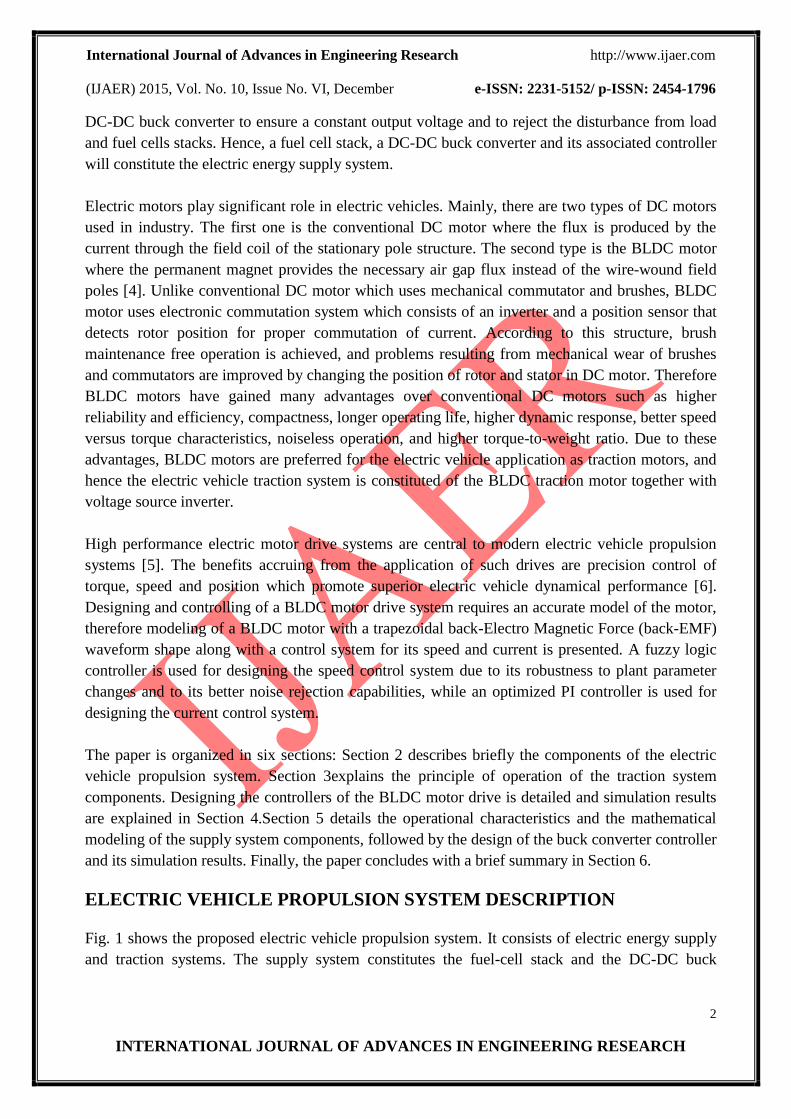
most applications due to its simplicity, lower price and higher efficiency [7]. The Simulink
diagram; Fig. 2, is drawn based on the standard electrical and mechanical equations of the BLDC
motor found in a variety of standard references (see for example [8, 9]).
Figure 2 Simulink model of BLDC motor
International Journal of Advances in Engineering Research http://www.ijaer.com
(IJAER) 2015, Vol. No. 10, Issue No. VI, December e-ISSN: 2231-5152/ p-ISSN: 2454-1796
4
INTERNATIONAL JOURNAL OF ADVANCES IN ENGINEERING RESEARCH
A three-phase trapezoidal stator windings BLDC motor requires three Hall sensors to detect its
rotor position, each hall sensor is typically mounted 120o apart and produces “1” whenever it faces
the North pole of the rotor, i.e. every 60o rotation. Therefore, it takes six steps to complete an
electrical cycle. The Hall sensor signals are fed to the control circuit which controls the direction
and speed of the motor by producing PWM signals for triggering the electronic switches; MOSFET
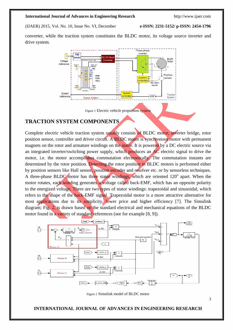
or IGBT, of the six-step inverter bridge via an interface driver. The inverter bridge structure is
shown in Fig. 3. In six-step inverter operation, only two winding are energized at a time. Each step
rotates at 60o, which six paths make a full 360
o rotation. One full 360
o loop is able to control the
current, due to the fact that there is only one current path. The switching sequence, the current
direction and the position signals are shown in Table I.
Table I Switching sequence of BLDC motor
Switching
interval
Sequence
no.
Position sensors Switch
closed
Phase current
Hall a Hall b Hall c a b C
330-30 I 1 0 1 S5 S4 off - +
30-90 II 1 0 0 S1 S4 + - off
90-150 III 1 1 0 S1 S6 + off -
150-210 IV 0 1 0 S3 S6 off + -
210-270 V 0 1 1 S3 S2 - + off
270-330 VI 0 0 1 S5 S2 - off +
Figure 3. Inverter bridge structure
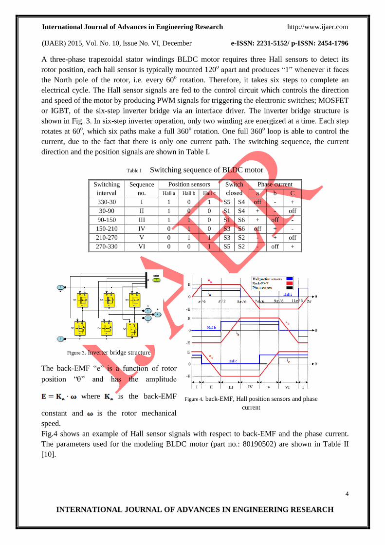
The back-EMF “e” is a function of rotor
position “” and has the amplitude
where is the back-EMF
constant and is the rotor mechanical
speed.
Figure 4. back-EMF, Hall position sensors and phase
current
Fig.4 shows an example of Hall sensor signals with respect to back-EMF and the phase current.
The parameters used for the modeling BLDC motor (part no.: 80190502) are shown in Table II
[10].
International Journal of Advances in Engineering Research http://www.ijaer.com
(IJAER) 2015, Vol. No. 10, Issue No. VI, December e-ISSN: 2231-5152/ p-ISSN: 2454-1796
5
INTERNATIONAL JOURNAL OF ADVANCES IN ENGINEERING RESEARCH
Table II BLDC motor technical specifications
Max. speed 8000 rpm Number of poles 4
Torque peak in 1160 mN.m Terminal resistance 0.24
Max. continuous torque 463 mN.m Torque constant 50.4 mN.m/A
Motor constant 103 mN.m/W1/2
Back-EMF constant 0.0504 V/(rad/s)
Rotor inertia 230 g.cm2
Inductance 0.6mH
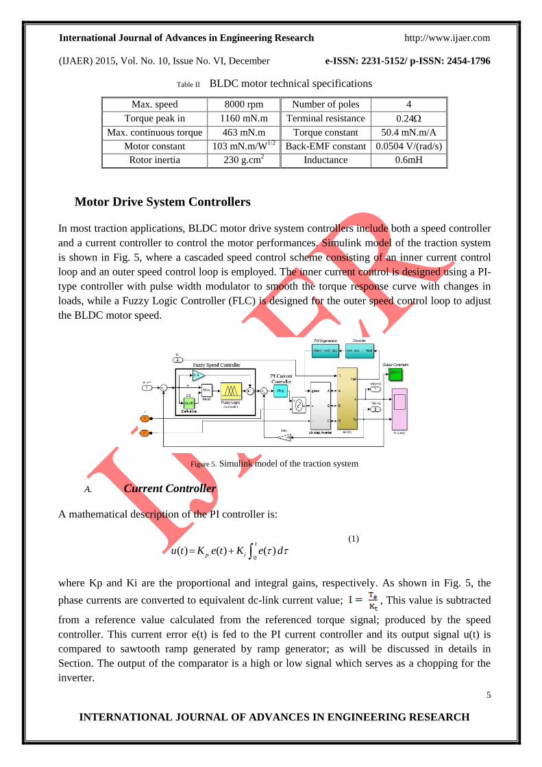
Motor Drive System Controllers
In most traction applications, BLDC motor drive system controllers include both a speed controller
and a current controller to control the motor performances. Simulink model of the traction system
is shown in Fig. 5, where a cascaded speed control scheme consisting of an inner current control
loop and an outer speed control loop is employed. The inner current control is designed using a PI-
type controller with pulse width modulator to smooth the torque response curve with changes in
loads, while a Fuzzy Logic Controller (FLC) is designed for the outer speed control loop to adjust
the BLDC motor speed.
Figure 5. Simulink model of the traction system
A. Current Controller
A mathematical description of the PI controller is:
0( ) ( ) ( )
t
p iu t K e t K e d
(1)
where Kp and Ki are the proportional and integral gains, respectively. As shown in Fig. 5, the
phase currents are converted to equivalent dc-link current value; , This value is subtracted
from a reference value calculated from the referenced torque signal; produced by the speed
controller. This current error e(t) is fed to the PI current controller and its output signal u(t) is
compared to sawtooth ramp generated by ramp generator; as will be discussed in details in
Section. The output of the comparator is a high or low signal which serves as a chopping for the
inverter.
International Journal of Advances in Engineering Research http://www.ijaer.com
(IJAER) 2015, Vol. No. 10, Issue No. VI, December e-ISSN: 2231-5152/ p-ISSN: 2454-1796
6
INTERNATIONAL JOURNAL OF ADVANCES IN ENGINEERING RESEARCH
Unlike traditional trial-and-error methods for obtaining PI parameters, a GUI provided by
Simulink Response Optimization Software (SROS) is used to tune the parameters within a
Simulink model to meet time-domain performance requirements by graphically placing constraints
within a time-domain window; as shown in Fig. 5 [11]. SROS automatically converts time-
domain constraints into a constrained optimization problem and then solves the problem using any
optimization technique. In this paper, gradient descent optimization technique is used.
After a few iterations, the optimal and feasible PI gains obtained were 9 and 0.015 related to Kp
and Ki, respectively.
B. Speed Controller
The speed controller is used to compare the desired reference speed (ωref) value with the actual
speed of the motor (ω). The angular velocities used as referenced velocities are shown in Table III.
Table III. Motor angular velocities
Process Time interval [min] Rotor speeds (rpm)
1 0 – 2 1800
2 2 – 10 2500
3 10 – 20 1800
3 20 – 65 3000
4 65 – 110 1800
5 110–118 2500
6 118–120 1800
7 120 0
A combination between FLC and proportional controller is used to control the speed of the BLDC
motor. FLC is designed using Mamdani style fuzzy inference system. FLC is chosen for its
robustness to plant parameter changes than classical controllers and for its capability to reject
noises. The basic structure of a FLC includes four blocks: (1) fuzzifire which converts input data
(real number or crisp variables) to suitable linguistic values, (2) rule base, (3) inference engine
which infer a fuzzy control action from knowledge of the rule base and the linguistic variable
definition, and (4) defuzzifier which transforms the linguistic variables again to crisp output.
Here FLC has two inputs and one output. These are speed error (E) and change in speed error (CE)
and reference current control signal, respectively. As shown in Fig. 5, speed error is the difference
between reference speed (ωref) and the actual speed of the motor (ω). There are seven clusters in the
membership functions as shown in Fig. 6. The definitions of the seven linguistic variables as well
as the rule base are presented in Table IV.
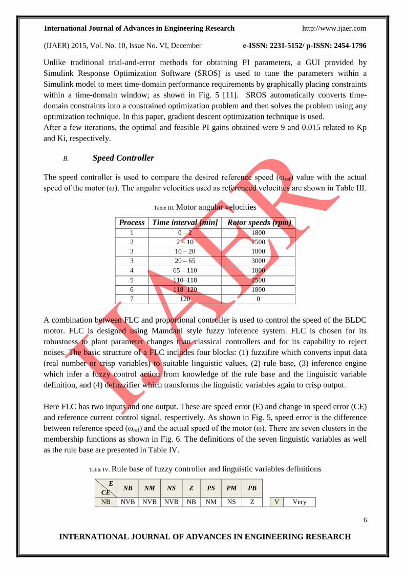
Table IV. Rule base of fuzzy controller and linguistic variables definitions
E
CE NB NM NS Z PS PM PB
NB NVB NVB NVB NB NM NS Z V Very
International Journal of Advances in Engineering Research http://www.ijaer.com
(IJAER) 2015, Vol. No. 10, Issue No. VI, December e-ISSN: 2231-5152/ p-ISSN: 2454-1796
7
INTERNATIONAL JOURNAL OF ADVANCES IN ENGINEERING RESEARCH
NM NVB NVB NB NM NS Z PS N Negative
NS NVB NB NM NS Z PS PM P Positive
Z NB NM NS Z PS PM PB S Small
PS NM NS Z PS PM PB PVB M Medium
PM NS Z PS PM PB PVB PVB B Big
PB Z PS PM PB PVB PVB PVB Z Zero
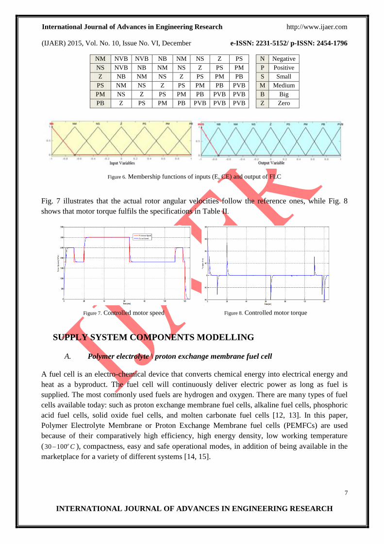
Figure 6. Membership functions of inputs (E, CE) and output of FLC
Fig. 7 illustrates that the actual rotor angular velocities follow the reference ones, while Fig. 8
shows that motor torque fulfils the specifications in Table II.
Figure 7. Controlled motor speed
Figure 8. Controlled motor torque
SUPPLY SYSTEM COMPONENTS MODELLING
A. Polymer electrolyte \ proton exchange membrane fuel cell
A fuel cell is an electro-chemical device that converts chemical energy into electrical energy and
heat as a byproduct. The fuel cell will continuously deliver electric power as long as fuel is
supplied. The most commonly used fuels are hydrogen and oxygen. There are many types of fuel
cells available today: such as proton exchange membrane fuel cells, alkaline fuel cells, phosphoric
acid fuel cells, solid oxide fuel cells, and molten carbonate fuel cells [12, 13]. In this paper,
Polymer Electrolyte Membrane or Proton Exchange Membrane fuel cells (PEMFCs) are used
because of their comparatively high efficiency, high energy density, low working temperature
( C10030 ), compactness, easy and safe operational modes, in addition of being available in the
marketplace for a variety of different systems [14, 15].
International Journal of Advances in Engineering Research http://www.ijaer.com
(IJAER) 2015, Vol. No. 10, Issue No. VI, December e-ISSN: 2231-5152/ p-ISSN: 2454-1796
8
INTERNATIONAL JOURNAL OF ADVANCES IN ENGINEERING RESEARCH
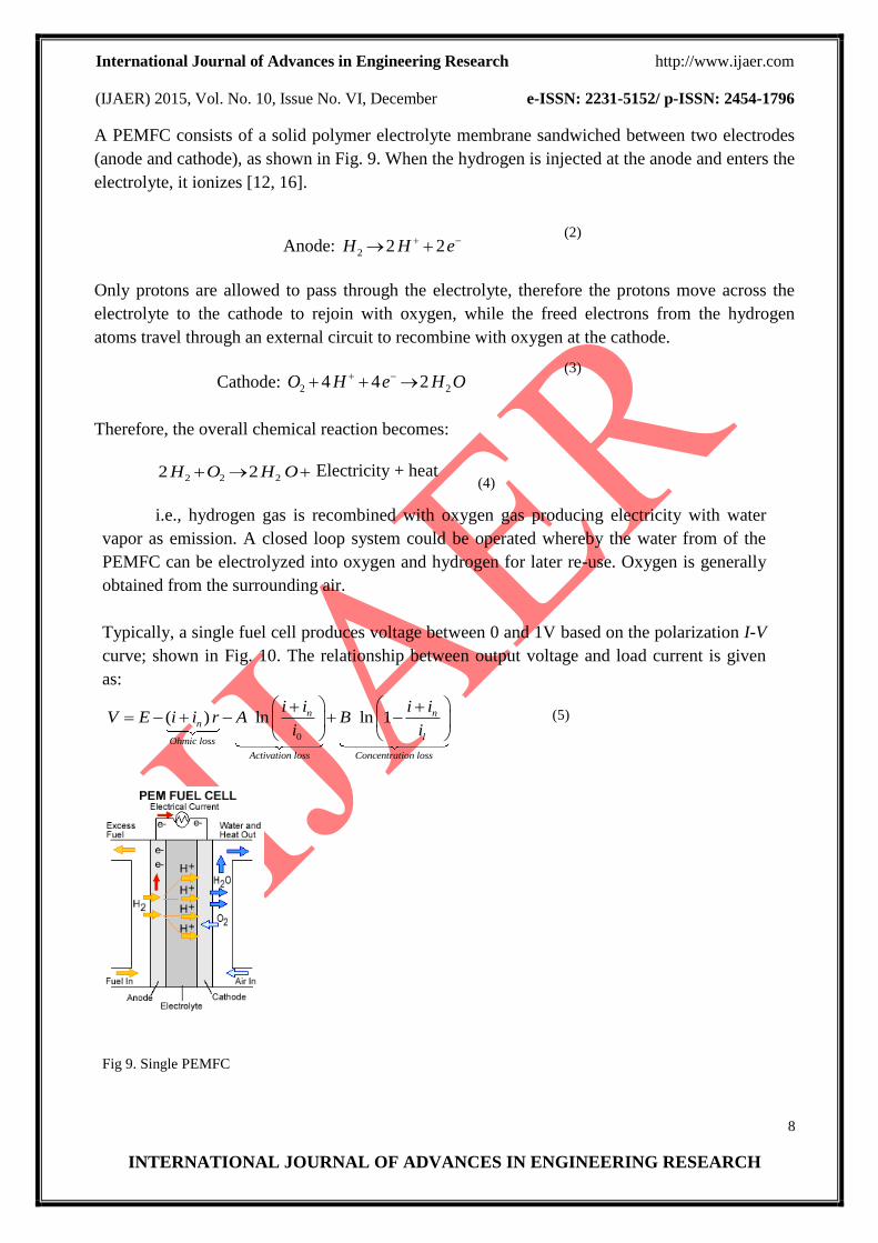
A PEMFC consists of a solid polymer electrolyte membrane sandwiched between two electrodes
(anode and cathode), as shown in Fig. 9. When the hydrogen is injected at the anode and enters the
electrolyte, it ionizes [12, 16].
Anode: eHH 222 (2)
Only protons are allowed to pass through the electrolyte, therefore the protons move across the
electrolyte to the cathode to rejoin with oxygen, while the freed electrons from the hydrogen
atoms travel through an external circuit to recombine with oxygen at the cathode.
Cathode: OHeHO 22 244
(3)
Therefore, the overall chemical reaction becomes:
OHOH 222 22 Electricity + heat
(4)
i.e., hydrogen gas is recombined with oxygen gas producing electricity with water
vapor as emission. A closed loop system could be operated whereby the water from of the
PEMFC can be electrolyzed into oxygen and hydrogen for later re-use. Oxygen is generally
obtained from the surrounding air.
Typically, a single fuel cell produces voltage between 0 and 1V based on the polarization I-V
curve; shown in Fig. 10. The relationship between output voltage and load current is given
as:
0
( ) ln ln 1n nn
lOhmic loss
Activation loss Concentration loss
i i i iV E i i r A B
i i
(5)
Fig 9. Single PEMFC
International Journal of Advances in Engineering Research http://www.ijaer.com
(IJAER) 2015, Vol. No. 10, Issue No. VI, December e-ISSN: 2231-5152/ p-ISSN: 2454-1796
9
INTERNATIONAL JOURNAL OF ADVANCES IN ENGINEERING RESEARCH
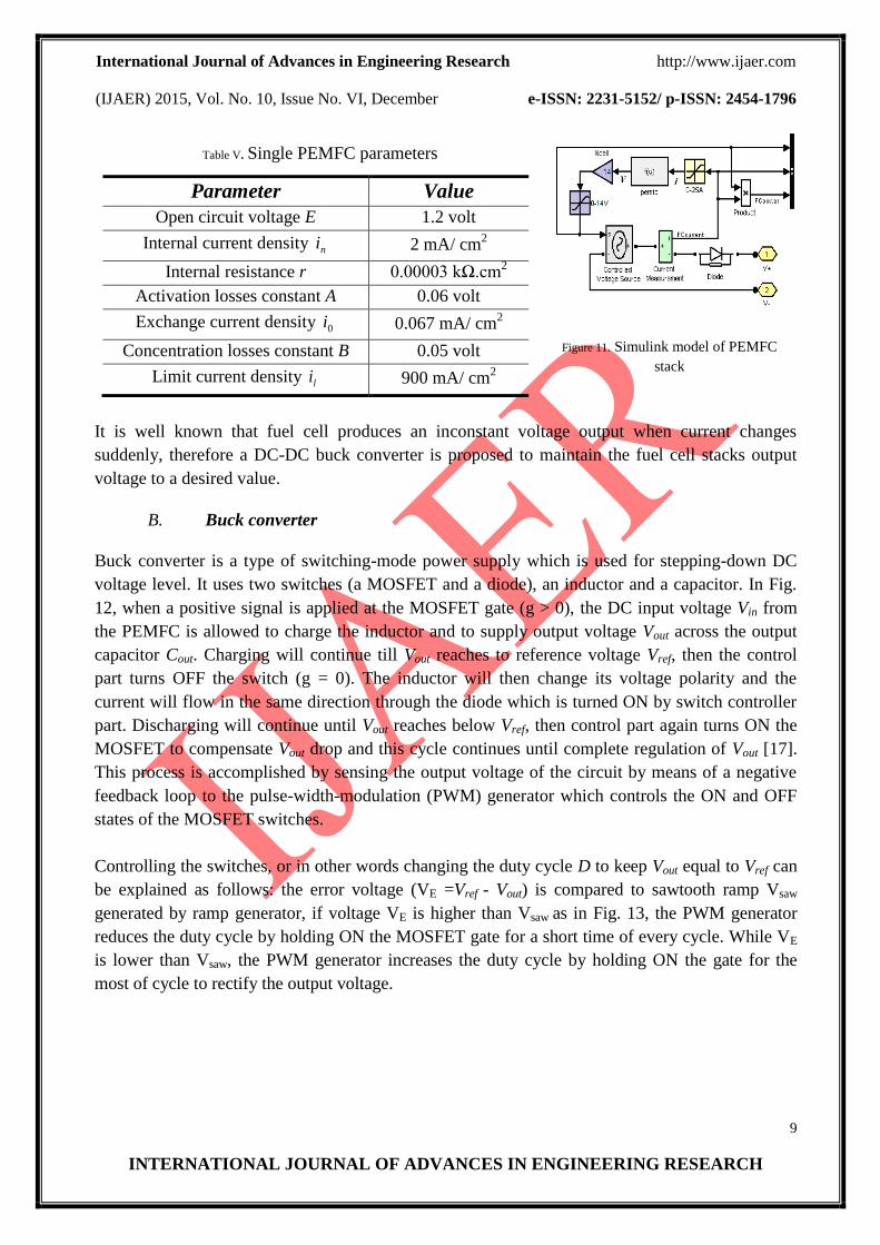
Table V. Single PEMFC parameters
Parameter Value
Open circuit voltage E 1.2 volt
Internal current density ni 2 mA/ cm2
Internal resistance r 0.00003 kΩ.cm2
Activation losses constant A 0.06 volt
Exchange current density 0i 0.067 mA/ cm2
Concentration losses constant B 0.05 volt
Limit current density li 900 mA/ cm2
Figure 11. Simulink model of PEMFC
stack
It is well known that fuel cell produces an inconstant voltage output when current changes
suddenly, therefore a DC-DC buck converter is proposed to maintain the fuel cell stacks output
voltage to a desired value.
B. Buck converter
Buck converter is a type of switching-mode power supply which is used for stepping-down DC
voltage level. It uses two switches (a MOSFET and a diode), an inductor and a capacitor. In Fig.
12, when a positive signal is applied at the MOSFET gate (g > 0), the DC input voltage Vin from
the PEMFC is allowed to charge the inductor and to supply output voltage Vout across the output
capacitor Cout. Charging will continue till Vout reaches to reference voltage Vref, then the control
part turns OFF the switch (g = 0). The inductor will then change its voltage polarity and the
current will flow in the same direction through the diode which is turned ON by switch controller
part. Discharging will continue until Vout reaches below Vref, then control part again turns ON the
MOSFET to compensate Vout drop and this cycle continues until complete regulation of Vout [17].
This process is accomplished by sensing the output voltage of the circuit by means of a negative
feedback loop to the pulse-width-modulation (PWM) generator which controls the ON and OFF
states of the MOSFET switches.
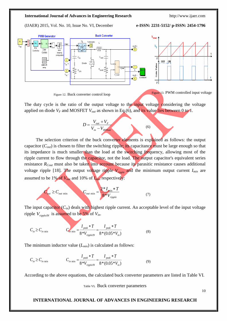
Controlling the switches, or in other words changing the duty cycle D to keep Vout equal to Vref can
be explained as follows: the error voltage (VE =Vref - Vout) is compared to sawtooth ramp Vsaw
generated by ramp generator, if voltage VE is higher than Vsaw as in Fig. 13, the PWM generator
reduces the duty cycle by holding ON the MOSFET gate for a short time of every cycle. While VE
is lower than Vsaw, the PWM generator increases the duty cycle by holding ON the gate for the
most of cycle to rectify the output voltage.
International Journal of Advances in Engineering Research http://www.ijaer.com
(IJAER) 2015, Vol. No. 10, Issue No. VI, December e-ISSN: 2231-5152/ p-ISSN: 2454-1796
10
INTERNATIONAL JOURNAL OF ADVANCES IN ENGINEERING RESEARCH
Figure 12. Buck converter control loop
Figure 13. PWM controlled input voltage
The duty cycle is the ratio of the output voltage to the input voltage considering the voltage
applied on diode VF and MOSFET Vout as shown in Eq.(6), and its value lies between 0 to 1.
RDSonin
Fout
VV
VVD
(6)
The selection criterion of the buck converter elements is explained as follows: the output
capacitor (Cout) is chosen to filter the switching ripple; its capacitance must be large enough so that
its impedance is much smaller than the load at the switching frequency, allowing most of the
ripple current to flow through the capacitor, not the load. The output capacitor's equivalent series
resistance RCout must also be taken into account because its parasitic resistance causes additional
voltage ripple [18]. The output voltage ripple rippleV and the minimum output current Imin are
assumed to be 1% of Vout and 10% of Iout, respectively:
ripple
outoutoutV
TICCC
*8
*2 minminmin
(7)
The input capacitor (Cin) deals with highest ripple current. An acceptable level of the input voltage
ripple INrippleV is assumed to be 5% of Vin.
)*05.0(*8*8minmin
in
peak
INripple
peak
inininV
TI
V
TICCC
(8)
The minimum inductor value (Lmin) is calculated as follows:
)*05.0(*8*8minmin
in
peak
INripple
peak
inininV
TI
V
TICCC
(9)
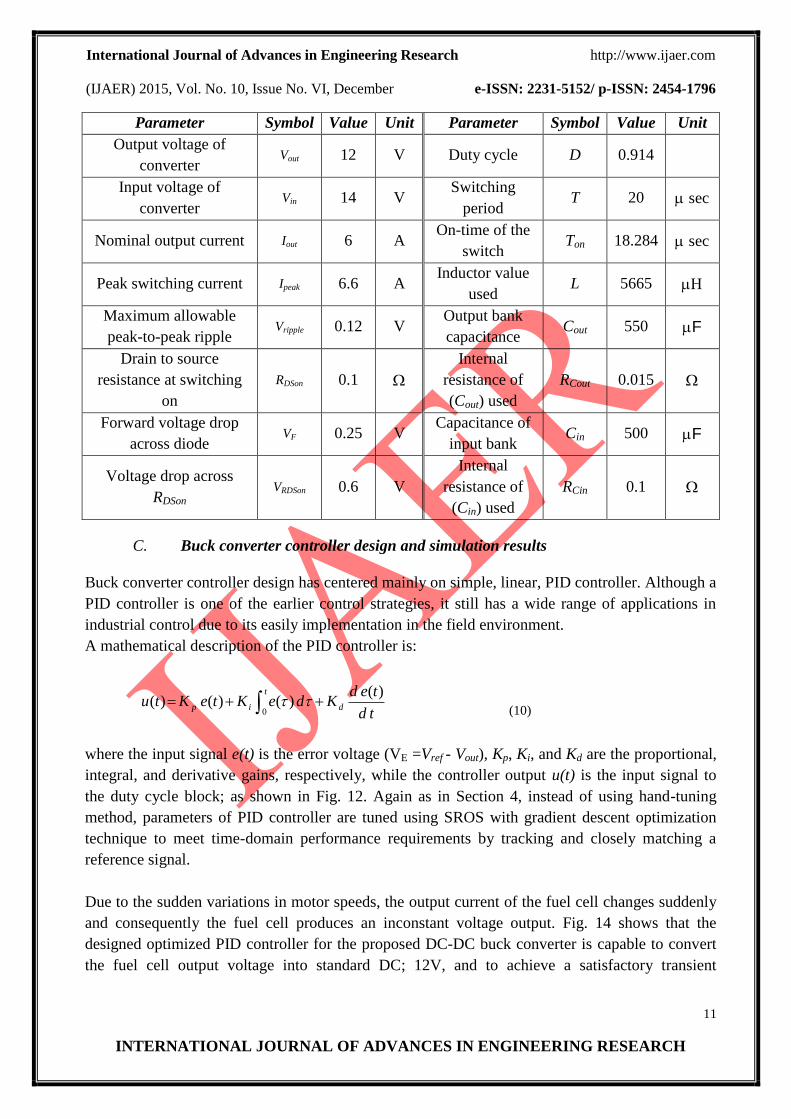
According to the above equations, the calculated buck converter parameters are listed in Table VI.
Table VI. Buck converter parameters
International Journal of Advances in Engineering Research http://www.ijaer.com
(IJAER) 2015, Vol. No. 10, Issue No. VI, December e-ISSN: 2231-5152/ p-ISSN: 2454-1796
11
INTERNATIONAL JOURNAL OF ADVANCES IN ENGINEERING RESEARCH
Parameter Symbol Value Unit Parameter Symbol Value Unit
Output voltage of
converter Vout 12 V Duty cycle D 0.914
Input voltage of
converter Vin 14 V
Switching
period T 20 sec
Nominal output current Iout 6 A On-time of the
switch Ton 18.284 sec
Peak switching current Ipeak 6.6 A Inductor value
used L 5665
Maximum allowable
peak-to-peak ripple Vripple 0.12 V
Output bank
capacitance Cout 550 F
Drain to source
resistance at switching
on
RDSon 0.1
Internal
resistance of
(Cout) used
RCout 0.015
Forward voltage drop
across diode VF 0.25 V
Capacitance of
input bank Cin 500 F
Voltage drop across
RDSon VRDSon 0.6 V
Internal
resistance of
(Cin) used
RCin 0.1
C. Buck converter controller design and simulation results
Buck converter controller design has centered mainly on simple, linear, PID controller. Although a
PID controller is one of the earlier control strategies, it still has a wide range of applications in
industrial control due to its easily implementation in the field environment.
A mathematical description of the PID controller is:
td
tedKdeKteKtu d
t
ip
)()()()(
0
(10)
where the input signal e(t) is the error voltage (VE =Vref - Vout), Kp, Ki, and Kd are the proportional,
integral, and derivative gains, respectively, while the controller output u(t) is the input signal to
the duty cycle block; as shown in Fig. 12. Again as in Section 4, instead of using hand-tuning
method, parameters of PID controller are tuned using SROS with gradient descent optimization
technique to meet time-domain performance requirements by tracking and closely matching a
reference signal.
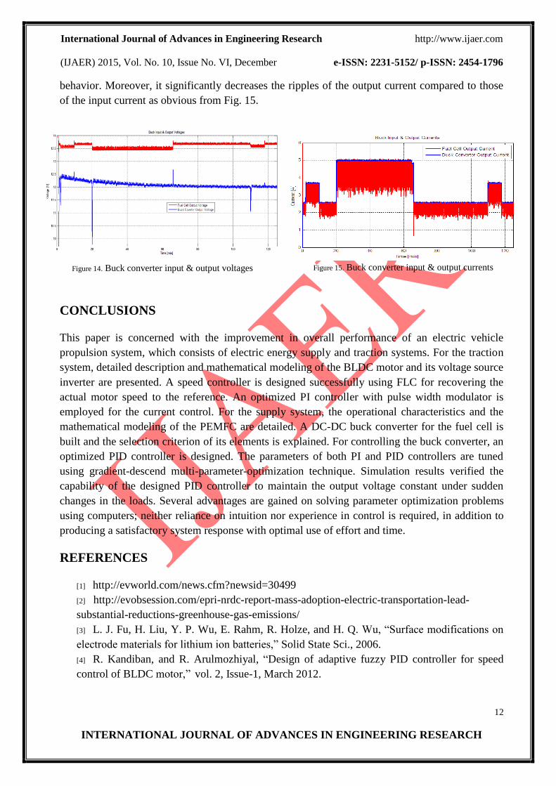
Due to the sudden variations in motor speeds, the output current of the fuel cell changes suddenly
and consequently the fuel cell produces an inconstant voltage output. Fig. 14 shows that the
designed optimized PID controller for the proposed DC-DC buck converter is capable to convert
the fuel cell output voltage into standard DC; 12V, and to achieve a satisfactory transient
International Journal of Advances in Engineering Research http://www.ijaer.com
(IJAER) 2015, Vol. No. 10, Issue No. VI, December e-ISSN: 2231-5152/ p-ISSN: 2454-1796
12
INTERNATIONAL JOURNAL OF ADVANCES IN ENGINEERING RESEARCH
behavior. Moreover, it significantly decreases the ripples of the output current compared to those
of the input current as obvious from Fig. 15.
Figure 14. Buck converter input & output voltages
Figure 15. Buck converter input & output currents
CONCLUSIONS
This paper is concerned with the improvement in overall performance of an electric vehicle
propulsion system, which consists of electric energy supply and traction systems. For the traction
system, detailed description and mathematical modeling of the BLDC motor and its voltage source
inverter are presented. A speed controller is designed successfully using FLC for recovering the
actual motor speed to the reference. An optimized PI controller with pulse width modulator is
employed for the current control. For the supply system, the operational characteristics and the
mathematical modeling of the PEMFC are detailed. A DC-DC buck converter for the fuel cell is
built and the selection criterion of its elements is explained. For controlling the buck converter, an
optimized PID controller is designed. The parameters of both PI and PID controllers are tuned
using gradient-descend multi-parameter-optimization technique. Simulation results verified the
capability of the designed PID controller to maintain the output voltage constant under sudden
changes in the loads. Several advantages are gained on solving parameter optimization problems
using computers; neither reliance on intuition nor experience in control is required, in addition to
producing a satisfactory system response with optimal use of effort and time.
REFERENCES
[1] http://evworld.com/news.cfm?newsid=30499
[2] http://evobsession.com/epri-nrdc-report-mass-adoption-electric-transportation-lead-
substantial-reductions-greenhouse-gas-emissions/
[3] L. J. Fu, H. Liu, Y. P. Wu, E. Rahm, R. Holze, and H. Q. Wu, “Surface modifications on
electrode materials for lithium ion batteries,” Solid State Sci., 2006.
[4] R. Kandiban, and R. Arulmozhiyal, “Design of adaptive fuzzy PID controller for speed
control of BLDC motor,” vol. 2, Issue-1, March 2012.
International Journal of Advances in Engineering Research http://www.ijaer.com
(IJAER) 2015, Vol. No. 10, Issue No. VI, December e-ISSN: 2231-5152/ p-ISSN: 2454-1796
13
INTERNATIONAL JOURNAL OF ADVANCES IN ENGINEERING RESEARCH
[5] A. Emadi, M. Ehsani, and Miller, J. M, “Vehicular electric power systems: land, sea, air,
and space vehicles,” CRC Press, 2003.
[6] J. Miller, “Propulsion Systems for Hybrid Vehicles,” IET, Renewable Energy, 2nd Edition,
2010.
[7] C. P. Singh, SS. Kulkarni, S.C. Rana, and K. Deo, “State-Space based simulink modeling
of BLDC motor and its speed control using fuzzy PID controller,” International Journal of
Advances in Engineering Science and Technology, Vol. 2, Number 3, pp. 359-369,2013.
[8] P. C. K. Luk and C. K. Lee, “Efficient modeling for a brushless DC motor drive,” In
Industrial Electronics, Control and Instrumentation, 1994. IECON'94., 20th International
Conference on. vol. 1. IEEE, 1994.
[9] P. C. Sen, “Principles of electric machines and power electronics,” John Wiley & Sons,
1997.
[10] http://media.oem.se/Archive/FilesArchive/29384.pdf
[11] A. Youssef, “Optimized PID tracking controller for piezoelectric hysteretic actuator
model,” World Journal of Modelling and Simulation, 2013, pp.223-234.
[12] L. Karunarathne, “An Intelligent Power Management System for Unmanned Aerial Vehicle
Propulsion Applications,” Ph.D. Thesis, Cranfield University, 2012.
[13] S. Mantravadi, “Modeling, Simulation and Implementation of Li-ion Battery Powered
Electric and Plug-in Hybrid Vehicles,” Master’s Thesis, University of Akron, 2011.
[14] J. Meyer, F. Plessis, et al. Aerial Vehicles, “ Design considerations for long endurance
unmanned aerial vehicles,” Intech, 2009.
[15] Committee on Materials, Structures, and Aeronautics Uninhabited Air Vehicles,
Uninhabited air vehicles enabling science for military systems, 2000.
[16] N. Safari, “Design of a DC/DC Buck Converter for Ultra-Low Power Applications in 65nm
CMOS Process,” Master’s Thesis, Linköping University, Sweden, 2012.
[17] EG&G Services, “Incorporation Fuel Cell Handbook, Science Applications International
Corporation,” 2004.
[18] R. Smith, “Design of a control strategy for a fuel cell-battery hybrid power supply,”
Master’s Thesis, Texas A & M University, USA, 2009.