Embed Size (px)
Citation preview

1
ELECTRIC WINCH WF08
WITH A CAPACITY OF 12000lb
2
SAFETY PRECAUTIONS Warning! Observe safety precautions for personal safety and the safety of others. Improper equipment operation may cause personal injury and equipment damage. Read the following carefully before attempting to operate your winch and keep the instructions for future reference. 1. Dress Properly: -Don’t wear loose clothing or jewellery. They can be caught in moving parts. -Wear leather gloves when handing winch cable. Do not handle cable with bare hands as broken
wires can cause injuries. -Non-skid footwear is recommended. -Protective hair covering to contain long hair. 2. Keep a Safe Distance: -Ensure that all persons stand well clear of winch cable and load during winch operation; 1.5 times
the cable length recommended .If a cable pulls loose or breaks under load it can lash back and cause serious personal injury or death.
-Don’t step over the cable. -All visitors and onlookers should be kept away from the work area. -Keep proper footing and balance at all times. 3. Don’t Abuse the Cord: -Never carry your winch by the cord or yank it to disconnect it from the receptacle. -Keep cord from heat, oil and sharp edges. 4. Don’t overwork the winch: -If the motor becomes uncomfortable hot to touch, stop and let it cool for a few minutes. -Don’t maintain power to the winch if the motor stalls. -Don’t exceed maximum line pull ratings shown in tables. Shock loads must not exceed these ratings. 5. Avoid Unintentional Starting: -Winch clutch should be disengaged when not in use and fully engaged when in use. 6. Check Damaged Parts: -Before using, you should check your winch carefully. And part that is damaged should be properly repaired or replaced by an authorized service centre. 7. Repair Your winch: -When repairing, use only identical replacement part or it may cause considerable dander for the user. -8.Respool the Cable: -Leather gloves must be worn while respooling. To respool correctly, it is necessary to keep a slight load on the cable. Hold the cable with one hand and the remote control switch with the other. Start as far back and in the centre as you can. Walk up keeping load on the cable as the winch is powered in. -Don not allow the cable to slop through your hand and do not approach the winch too closely. -Turn off the winch and repeat the procedure until all the cable except 1m is in. -Disconnect the remote control switch and finish spooling in cable by rotating the drum by hand with clutch disengaged. -On hidden winches, spool in cable under power but keep hands clear. Warning: The use of any other accessory or attachment other than those recommended in the instruction manual may present a risk of personal injury.

3
- WINCH OPERATION WARNINGS Read the following carefully before attempting to operate your winch and keep the instructions for future reference.
1. The uneven spooling of cable, while pulling a load, is not a problem, unless there is a cable pile up on one end of the drum. If this happens reverse the winch to relieve the load and move your anchor point further to the centre of the vehicle. After the job is done you can unspool and rewind for a neat lay of the cable.
2. Store the remote control switch inside your vehicle where it will not become damaged, inspect it before you plug it in.
3. When ready to begin spooling in, plug in remote control switch with clutch disengaged, do not engage clutch with motor running.
4. Never connect the hook back to the cable. This causes cable damage. Always use a sling or chain of suitable strength.
5. Observe your winch while winching, if possible while standing at a safe distance. Stop the winching process every meter or so to assure the cable is not pulling up in one corner. Jamming the cable can break your winch.
6. Do not attach tow hooks to winch mounting appartus. They must be attached to vehicle frame.
7. The use of a snatch block will aid recovery operations by providing a doubling of the winch capacity and a halving of the winching speed, and the means to maintain a direct line pull to the centre of the rollers. When double loading during stationary winching, the winch hook should be attached to the chassis of the vehicle.
8. Ensure rated “D” or bow shackles are used in conjunction with an approved tree trunk protector to provide a safe anchor point.
9. When extending winch cable, ensure that at least five wraps of cable remain on drum at all times. Failure to do this could result in the cable parting from the drum under load. Serious personal injury or property damage may result.
10. All the winches are provided with a Red Cable marking to identify that 5 cable wraps remain on the Winch drum when this mark appears at the rollers. No recovery should be attempted beyond this marking.
11. Since the greatest pulling power is achieved on the innermost layer of your winch, it is desireable to pull off as much line as you can for heavy pulls (you must leave at least 5 wraps minimum on the drum-red cable). If this is not practical use a snatch block and double line arrangement.
12. Draping a heavy blanket or similar object over the extended winch cable is recommended as it will dampen any back lash should a failure occur.
13. Neat, tight spooling avoids cable binding, which is caused when a load is applied and the cable is pinched between the others. If this happens, alternatively power the winch in and out. Do not attempt to work a bound cable under load, free by hand.
14. Apply blocks to wheels when vehicles are on an incline. 15. Battery:
-Be sure that the battery is in good condition. Avoid contact with battery acid or other contaminants.
-Always wear eye protection when working around a battery.

4
16.Winch Cable:
-Be sure that the cable is in good condition and is attached properly. -Do not use the winch if cable is frayed. -Do not move the vehicle to pull a load. -Do not replace the cable with a cable of lesser strength. -The life of the cable is directly related to the use and care it receives. Following its first and
subsequent uses, a cable must be wound on to the drum under a load of at least 500lbs(230kg) or the outer wraps will draw into the inner wraps and severely damage the cable during winching. The first winch use should be a familiarisations run while in a relaxed, non-recovery situation. Spool out the cable until the red cable mark appears (about five wraps on the drum), then rewind the cable on to the drum under a load of 500lbs(230kg) or more. This will slightly tension and stretch the new cable and create a tight cable wrap around the drum. Failure to do so may result in cable damage and reduced cable life.
-When the cable is replaced, be sure to apply loctite, or an equal compound, to the cable clamp thread. Tighten the clamp screw properly but do not overtighten. The locktite will prevent loosening of the screw in arduous conditions. Loctite 7471Primer and 222 Threadlocker are recommended.
17.Do not attempt to exceed the pulling limits of this winch. 18.DO NOT drive your vehicle to assist the winch in any way. Vehicle movement in
combination with operation may overload the cable, the winch itself or cause damaging shock loads.
19.Shock loads when winching are dangerous! A shock load occurs when an increased force is suddenly applied to the cable. A vehicle rolling back on a slack cable may induce a damaging shock load.
20.The winches shown in this manual are solely for vehicle and boat mounted, non-industrial applications.
21.Do not use winch in hoisting applications due to required hoist safety factors and features. 22.Do not use the winch to life, support or otherwise transport personnel. ATTENTION: 1. The cable stop spooling auotomatically while overloading. The sound of grating or alarm
tone means the pull has overed 12000lb and over-load protection is working. Please disconnect the remote control switch and power off, using pully block to increase the winch disconnect operation affects life span of winch.
2. Rubber sealers are installed between the drum and two brackets, which protect winch from dust and water.

5
INSTALLATION MOUNTING YOUR WINCH 1a)The winch is to be mounted into a suitable steel mounting frame using the 4 point foot mounting system in either a horizontal or vertical plane. b) It’s very important that the winch be mounted on a flat surface so that three sections (motor, cable drum and gear housing) are properly aligned. c)Before commencing installation ensure the mounting facility being used is capable of withstanding the winches rated capacity. d) The fitment of winched and / or a frontal protection system may affect the triggering of SRS air bags. Check that the mounting system has been tested and approved for winch fitment in the airbag equipped vehicle. 2. Winch mounting frames and / or Frontal Protection system are suggested to suit most popular vehicles. Winch frames are packaged with detailed fitting instructions. 3. Should you wish to manufacture your own mounting plate the dimensions below will assist. A steel mount plate 6mm thick is recommended. Fasteners should be steel high tensile grade 5 or better. A poorly designed mount may void warranty. 4. The winch should be secured to the mounting with 3/8〞UNC*1-1/4〞stainless steel bolts and spring washers provided. 5. The roller fairlead is to be mounted so as to guide the rope onto the drum evenly.
LUBRICATION INSTALLATION All moving parts in the winch are permanently lubricated with high temperature lithium grease at the time of assembly. Under normal conditions factory lubrication will surfice. Lubricate cable periodically using light penetrating oil. Inspect for broken strands and replace if necessary. If the cable becomes worn or damaged it must be replaced. Cable installation Unwind the new cable by rolling it along the ground, to prevent kinking. Remove old cable and observe the manner in which it is attached to the cable drum flange.

6
LECTRICAL CONNECTION For normal self-recovery work, your existing electrical system is adequate. A fully charged battery and proper connections are essential. Run the vehicle engine during winching operations to keep battery charged. Pay chose attention to proper electrical cable connection as follows (refer to Diagram 1) 1. Short red cable (B’) connecting to the red terminal (B) of the motor. 2. Short black cable with yellow jacket(C’) connecting to the yellow terminal (C) of the motor 3. Short black cable with black jacket(D’) connecting to the black terminal (D) of the motor 4. Thin black cable (a’) connecting to bottom terminal (A) of the motor. 5. Long black cable (1.8m), one terminal (A’) connecting to the bottom terminal (A) of the motor,
and the other terminal negative(-) connecting to negative(-) terminal of battery. 6. Long red cable positive (+) connecting to positive (+) terminal of battery.
NOTE: 1. Your battery must be kept in good condition. 2. Be sure battery cables are not drawn taught across any surfaces, which could possibly damage
them. 3. Corrosion on electrical connections will reduce performance or may cause a short. 4. Clean all connections especially in remote control switch and receptacle. 5. In salty environments use a silicone sealer to protect from corrosion. 6. Index the heads of the plate studs into the keyhole slots on the back of the winch. 7. Attach the winch/Adaptor Plate assembly to your trailer hitch, by inserting the trailer hitch
ball through the shaped hole in the Adaptor Plate. WARNING: Winches of 12V can ONLY be connected to 12V batteries; and winches of 24V can ONLY be connected to 24V batteries.

7

8
WINCH OPERATION SUGGESTION: The best way to get acquainted with how your winch operates is to make a few test runs before you actually need to use it. Plan your test in advance. Remember you can hear your winch as well as you can see it operate. Get to recognize the sound of a light steady pull, a heavy pull, and sounds caused by load jerking or shifting. Soon you will gain confidence in operating your winch and its use will become second nature to you. OPERATION 1. Ensure the vehicle is secure by applying the parking brake or chocking the wheels. 2. Pull out the winch cable the desired length and connect to an anchor point. The winch clutch allows rapid uncoiling of the cable for hooking onto the load or anchor point. The shifter tab located on the gear housing of the winch operates the clutch as follows: a) To disengage the clutch, move the clutch shifter tab to the “free spool” position. Cable may
not be free spooled off the drum. b) To engage the clutch, move the clutch shifter tab into the “engaged” position. The winch is
now ready for pulling. 3. Recheck all cable rigging before proceeding. 4. Plug in the winch hand control. It is recommended that the winching operation takes place
from the driver’s position to ensure safe operation. 5. To commence winching operation, start vehicle engine, select neutral in transmission,
maintain engine speed at idle. 6. Operate the remote control switch to IN or OUT until the vehicle has been retrieved.
Regularly check the winch to ensure cable is winching onto the drum evenly. 7. Operate the wireless remote control switch to “enter” or “let out” until the vehicle has been
retrieved. Note: 1. Never winch with your vehicle in gear or in park, which would damage your vehicle’s
transmission. 2. Never wrap the cable around the object and hook onto the cable itself. This can cause damage
to the object being pulled, and kink or fray the cable. 3. Keep hands, clothing, hair and jewellery clear of the drum area and cable when winching. 4. Never use the winch if the cable is frayed, kinked or damaged. 5. Never allow anyone to stand near the cable, or in line with the cable behind the winch while it
is under power. If the cable should slip or brake, it can suddenly whip back towards the winch, causing a hazard for anyone in the area. Always stand well to the side while winding.
6. Don’t leave the switch plugged in when winch is not in use. CHECK THE WINCH CAREFULLY AND THOROUGHLY BEFORE OPERATION! MAINTENANCE It is highly recommended that the winch be used regularly (once a month). Simply power the cable out 15m, free spool 5m and then power back in. This will keep all components in good working condition so that the winch can be relied on when needed. Contact your authorised outlet for technical assistance and repairs. SPARE PARTS: A comprehensive range of spare parts is available.

9
Winching capacity 1. This winch has a capacity of 12000lbs 2. Pulling capacity is reduced as the incline increases. Recommended safe loads for various
inclines are listed in table below: Rated Line Pull 10% 20% 40% 60% 80% 100%
1500lb 7538 5102 3233 2496 2134 1928 2000lb 10050 6803 6347 2816 2407 2175 2500lb 12563 8503 5388 4160 3556 3213 3500lb 17588 11905 7543 5824 4979 4499 6000lb 30151 20408 12931 9983 8535 7712 8500lb 42670 28900 18275 14110 12070 10880 9000lb 42714 28912 18319 14167 12093 10925 9500lb 47690 32300 20425 15770 13490 12160
10000lb 47739 32313 20474 15833 13515 12211 12000lb 60240 40800 25800 19920 17040 15360
Note: 1. This guide is recommended for average vehicle rolling loads. Some applications require a
larger winch than indicated. 2. The weight the winch could pull perpendicular to the ground with a single line on the first
layer of cable on the drum. 3. A 10% grade is a rise of one metre in ten metre. 4. Winch is not intended as a load securing device. NOTE: The safety precautions and instructions discussed in this manual can’t cover all possible conditions and situations that may occur. It must be understood by the operator that common sense and caution are factors, which cannot be built into this product, but must be applied by the operator.

10
Press “►” on control box, use hand remote control. Level the Shift switch when winch is not in use
Press “◄”on control box, use wireless remote control level the Shift switch when winch is not in use

11
12000LBS FEATURES AND SPECIFICATIONS Single Line Rated Pull 12000lb (5440kg) Motor 12V 6.6hp/ 4.8kw, 24V 4.0hp/3.0kw,series wound control Remote Switch, 12ft (3.7m) lead Gear train 3 Stage Planetary Gear reduction ration 187.2:1 Braking Action Automatic In-The-Drum Cable 94ft of 3/8〞diameter (28m of 9.1mm diameter) Main body Sealed Effected protection 5600kg-5750kg Fairlead 4-Way Roller Fairlead Battery Leads 2gauge,72〞(1.83m) Overall dimensions (L*W*H)20.4〞*6.3〞*8.6〞(537*160*218mm) Mounting Bolt Pattern 10.00 ± 0.015〞*4.50±0.010〞(254*114.3mm)
12V DC LINE SPEED AND AMP DRAW(FIRST LAYER) Line Pull (lbs./kg) Line Speed FPM(m/min) Motor(Amps)
0 33.3ft(10.3m) 85 4000(1810) 16.8ft(5.1m) 158 6000(2720) 12.8ft(3.9m) 231 8000(3630) 10.1ft(3.1m) 302
10000(4540) 8.8ft(2.7m) 371 12000(5440) 7.6ft(2.3m) 450 12300(5590) 0ft(0m) 200
24V LINE SPEEED AND AMP DRAW(FIRST LAYER) Line Pull(lbs./kg) Line Speed FPM(m/min) Motor(Amps)
0 35.0ft(10.8m) 50 4000(1810) 18.5ft(5.6m) 130 6000(2720) 14.4ft(4.4m) 170 8000(3630) 11.5ft(3.5m) 210
10000(4540) 10.0ft(3.1m) 240 12000(5440) 8.9ft(2.7m) 280 12300(5590) 0ft(0m) 100
12
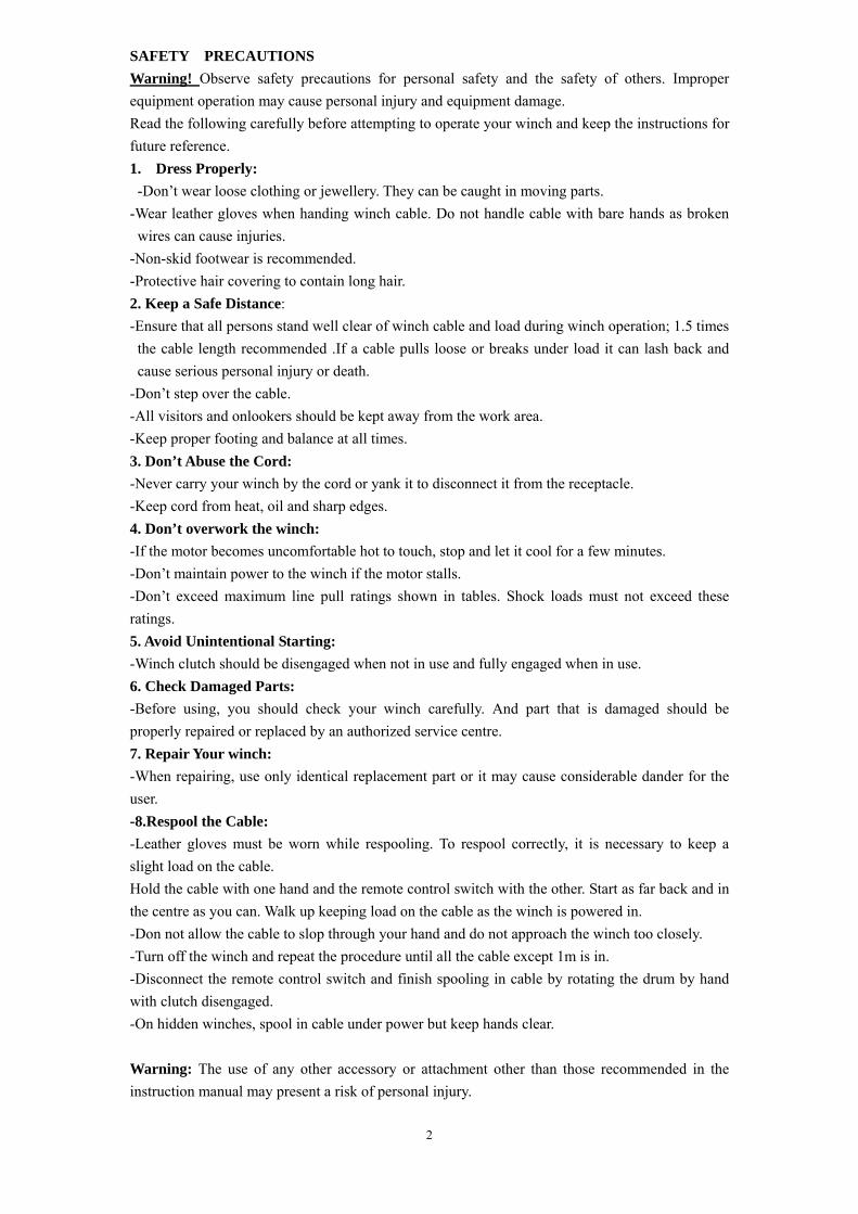
12000LBS LINE PULL AND CABLE CAPACITY Layer of cable 1 2 3 4
Lbs 12000 9210 8030 6894 Rated line pull per layer Kgs 5440 4170 3640 3125
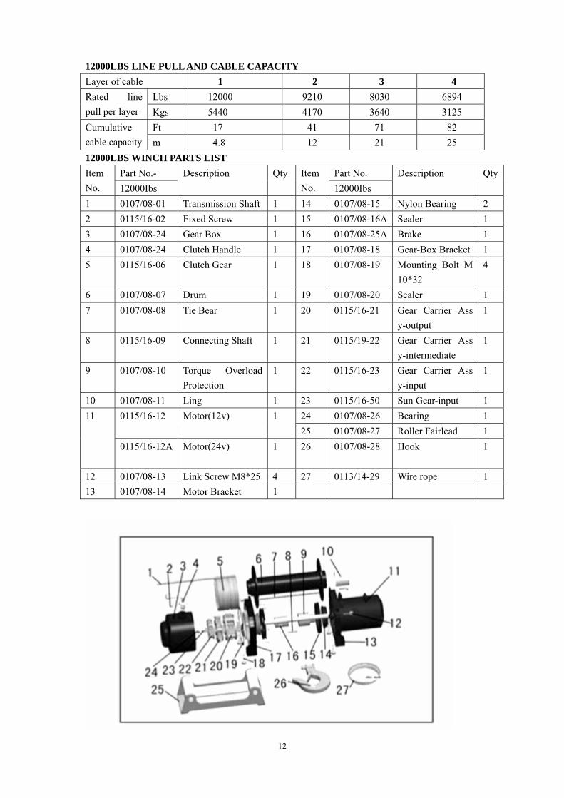
Ft 17 41 71 82 Cumulative cable capacity m 4.8 12 21 25 12000LBS WINCH PARTS LIST
Part No.- Part No. Item No. 12000Ibs
Description Qty Item No. 12000Ibs
Description
Qty
1 0107/08-01 Transmission Shaft 1 14 0107/08-15 Nylon Bearing 2 2 0115/16-02 Fixed Screw 1 15 0107/08-16A Sealer 1 3 0107/08-24 Gear Box 1 16 0107/08-25A Brake 1 4 0107/08-24 Clutch Handle 1 17 0107/08-18 Gear-Box Bracket 1 5 0115/16-06 Clutch Gear 1 18 0107/08-19 Mounting Bolt M
10*32 4
6 0107/08-07 Drum 1 19 0107/08-20 Sealer 1 7 0107/08-08 Tie Bear 1 20 0115/16-21 Gear Carrier Ass
y-output 1
8 0115/16-09 Connecting Shaft 1 21 0115/19-22 Gear Carrier Ass y-intermediate
1
9 0107/08-10 Torque Overload Protection
1 22 0115/16-23 Gear Carrier Ass y-input
1
10 0107/08-11 Ling 1 23 0115/16-50 Sun Gear-input 1 24 0107/08-26 Bearing 1 0115/16-12 Motor(12v) 1
25 0107/08-27 Roller Fairlead 1 11
0115/16-12A Motor(24v)
1 26 0107/08-28 Hook 1
12 0107/08-13 Link Screw M8*25 4 27 0113/14-29 Wire rope 1 13 0107/08-14 Motor Bracket 1

13
OLENOID BOX ASSEMBLY (12V/24V) PARTS LIST Item No. Part No. Description Qty
1 So107/08-30 Cover-solenoid Ass’y 1 2 So107/08-31 Cable(Brown 0.75mm2X25cm; to the battery”+”) 1 3 So107/08-32 Cable(Brown 0.75mm2X25cm; Power in) 1 4 So107/08-33 0.425m Short Black Cable with Yellow Terminal Sleeve 1 5 So107/08-34 Bracket 1 6 So107/08-35 ScrewM5X12 3
So107/08-36 Solenoid-Power in 12V 1 7 So107/08-36A Solenoid-Power in 24V 1
8 So107/08-37 0.425m Short Red Cable with Red Terminal Sleeve 1 9 So107/08-38 1.8m Long Red Cable 1
10 So107/08-39 Black Cable with Black Sleeve(0.75mmx0.45m;earth) 1 11 So107/08-40 Strap-Aluminum 1 12 So107/08-41 U Type Strap-Aluminum 1
So107/08-42 Solenoid-Power in 12V 1 13 So107/08-42A Solenoid-Power in 24V 1
14 So107/08-43 0.425m Short Black Cable with Black Terminal Sleeve 1 15 So107/08-44 Cable(Black 0.75mm2X25cm; Power Out) 1 16 So107/08-45 Female Connector Ass’y 1