Embed Size (px)
Citation preview
51
Electrical and Electronic Components
Chapter 3
Explain the purpose of circuit protection devices. ■
Describe the most common types in use.
Defi ne circuit defects, including opens, shorts, ■
grounds, and excessive resistance.
Explain the eff ects that each type of circuit defect has ■
on the operation of the electrical system.
Upon completion and review of this chapter, you should be able to:
Describe the common types of electrical system ■
components used and how they aff ect the electrical system.
Explain the operation of the electrical controls, ■
including switches, relays, and variable resistors.
Describe the basic operating principles of ■
electronic components.
Explain the use of electronic components in the ■
circuit.
IntroductionIn this chapter you will be introduced to electrical and electronic components. These components include circuit protection devices, switches, relays, variable resistors, diodes, and different forms of transistors. Today’s technician must comprehend the oper-ation of these components and the ways they affect electrical system operation. With this knowledge, the technician will be able to accurately and quickly diagnose many electrical failures.
To be able to properly diagnose the components and circuits, the technician must be able to use the test equipment that is designed for electrical system diagnosis. In this chapter you will learn about the various types of test equipment used for diagnosing electrical systems. You will learn the appropriate equipment to use to locate the fault based on the symptoms. In addition, the various types of defects that cause the system to operate improperly are discussed.
Electrical ComponentsElectrical circuits require diff erent components depending on the type of work they do and how they are to perform it. A light may be wired directly to the battery, but it will remain on until the battery drains. A switch will provide for control of the light circuit. However, if vari-able dimming of the light is required, a rheostat is also needed.
Th ere are several electrical components that may be incorporated into a circuit to achieve the desired results from the system. Th ese components include switches, relays, buzzers, and various types of resistors.
52
Switches
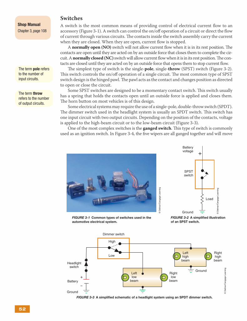
A switch is the most common means of providing control of electrical current fl ow to an accessory (Figure 3-1). A switch can control the on/off operation of a circuit or direct the fl ow of current through various circuits. Th e contacts inside the switch assembly carry the current when they are closed. When they are open, current fl ow is stopped.
A normally open (NO) switch will not allow current fl ow when it is in its rest position. Th e contacts are open until they are acted on by an outside force that closes them to complete the cir-cuit. A normally closed (NC) switch will allow current fl ow when it is in its rest position. Th e con-tacts are closed until they are acted on by an outside force that opens them to stop current fl ow.
Th e simplest type of switch is the single-pole, single-throw (SPST) switch (Figure 3-2). Th is switch controls the on/off operation of a single circuit. Th e most common type of SPST switch design is the hinged pawl. Th e pawl acts as the contact and changes position as directed to open or close the circuit.
Some SPST switches are designed to be a momentary contact switch. Th is switch usually has a spring that holds the contacts open until an outside force is applied and closes them. Th e horn button on most vehicles is of this design.
Some electrical systems may require the use of a single-pole, double-throw switch (SPDT). Th e dimmer switch used in the headlight system is usually an SPDT switch. Th is switch has one input circuit with two output circuits. Depending on the position of the contacts, voltage is applied to the high-beam circuit or to the low-beam circuit (Figure 3-3).
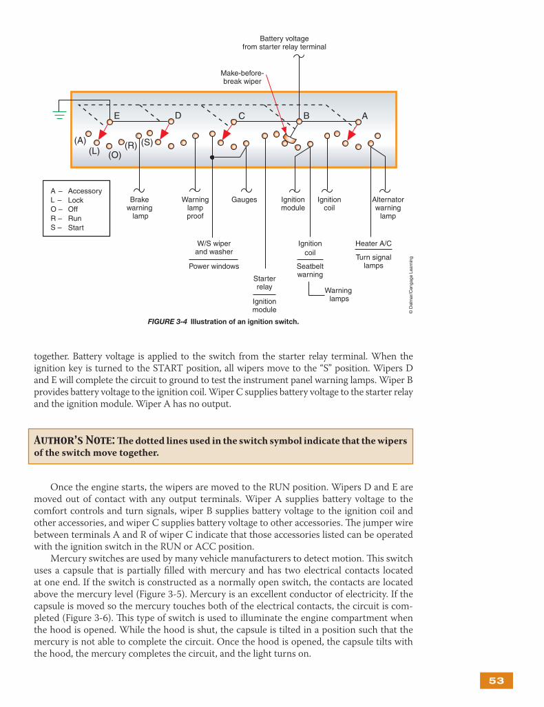
One of the most complex switches is the ganged switch. Th is type of switch is commonly used as an ignition switch. In Figure 3-4, the fi ve wipers are all ganged together and will move
Shop Manual
Chapter 3, page 108
The term pole refers to the number of input circuits.
The term throw refers to the number of output circuits.
FIGURE 3-1 Common types of switches used in the
automotive electrical system.
© D
elm
ar/C
enga
ge L
earn
ing
+Batteryvoltage
SPSTswitch
Load
Ground
FIGURE 3-2 A simplifi ed illustration
of an SPST switch.
© D
elm
ar/C
enga
ge L
earn
ing
FIGURE 3-3 A simplifi ed schematic of a headlight system using an SPDT dimmer switch.
+Battery
GroundLeftlow
beam
High
Low
Ground
Headlightswitch
Lefthigh
beam
Righthigh
beam
Rightlow
beam
Dimmer switch
© D
elm
ar/C
enga
ge L
earn
ing
53
together. Battery voltage is applied to the switch from the starter relay terminal. When the ignition key is turned to the START position, all wipers move to the “S” position. Wipers D and E will complete the circuit to ground to test the instrument panel warning lamps. Wiper B provides battery voltage to the ignition coil. Wiper C supplies battery voltage to the starter relay and the ignition module. Wiper A has no output.
Once the engine starts, the wipers are moved to the RUN position. Wipers D and E are moved out of contact with any output terminals. Wiper A supplies battery voltage to the comfort controls and turn signals, wiper B supplies battery voltage to the ignition coil and other accessories, and wiper C supplies battery voltage to other accessories. Th e jumper wire between terminals A and R of wiper C indicate that those accessories listed can be operated with the ignition switch in the RUN or ACC position.
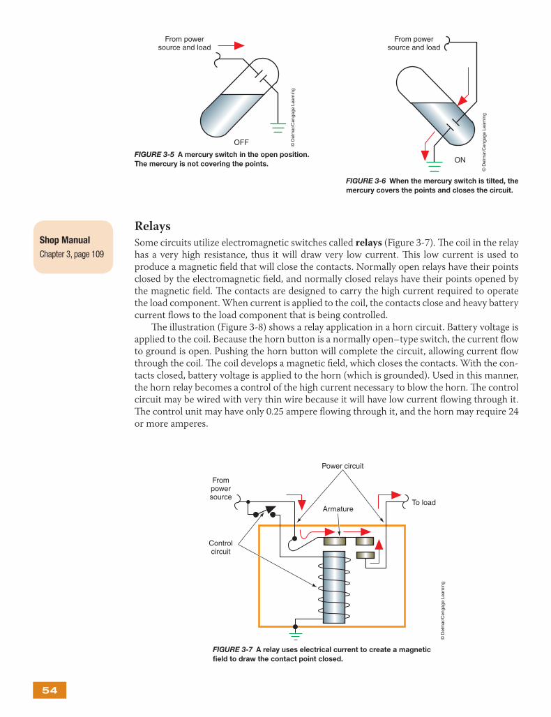
Mercury switches are used by many vehicle manufacturers to detect motion. Th is switch uses a capsule that is partially fi lled with mercury and has two electrical contacts located at one end. If the switch is constructed as a normally open switch, the contacts are located above the mercury level (Figure 3-5). Mercury is an excellent conductor of electricity. If the capsule is moved so the mercury touches both of the electrical contacts, the circuit is com-pleted (Figure 3-6). Th is type of switch is used to illuminate the engine compartment when the hood is opened. While the hood is shut, the capsule is tilted in a position such that the mercury is not able to complete the circuit. Once the hood is opened, the capsule tilts with the hood, the mercury completes the circuit, and the light turns on.
Author’s Note: Th e dotted lines used in the switch symbol indicate that the wipers of the switch move together.
FIGURE 3-4 Illustration of an ignition switch.
Warninglampproof
Brake warning
lamp
Gauges Ignitionmodule
W/S wiperand washer
Power windows
Ignitioncoil
Seatbeltwarning
Ignitioncoil
A –L –O –R –S –
AccessoryLockOffRunStart
Heater A/C
Turn signallamps
Starterrelay
Ignitionmodule
Warning lamps
Alternatorwarning
lamp
Make-before-break wiper
Battery voltagefrom starter relay terminal
(A)(L) (O)
(R) (S)
E D C B A
© D
elm
ar/C
enga
ge L
earn
ing
54
Relays
Some circuits utilize electromagnetic switches called relays (Figure 3-7). Th e coil in the relay has a very high resistance, thus it will draw very low current. Th is low current is used to produce a magnetic fi eld that will close the contacts. Normally open relays have their points closed by the electromagnetic fi eld, and normally closed relays have their points opened by the magnetic fi eld. Th e contacts are designed to carry the high current required to operate the load component. When current is applied to the coil, the contacts close and heavy battery current fl ows to the load component that is being controlled.
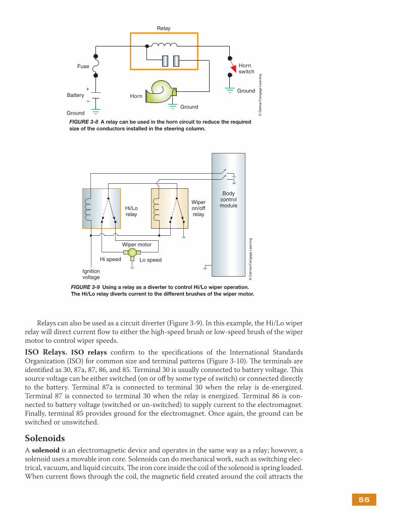
Th e illustration (Figure 3-8) shows a relay application in a horn circuit. Battery voltage is applied to the coil. Because the horn button is a normally open–type switch, the current fl ow to ground is open. Pushing the horn button will complete the circuit, allowing current fl ow through the coil. Th e coil develops a magnetic fi eld, which closes the contacts. With the con-tacts closed, battery voltage is applied to the horn (which is grounded). Used in this manner, the horn relay becomes a control of the high current necessary to blow the horn. Th e control circuit may be wired with very thin wire because it will have low current fl owing through it. Th e control unit may have only 0.25 ampere fl owing through it, and the horn may require 24 or more amperes.
Shop Manual
Chapter 3, page 109
From powersource and load
OFF
FIGURE 3-5 A mercury switch in the open position.
The mercury is not covering the points.
© D
elm
ar/C
enga
ge L
earn
ing
From powersource and load
ON
FIGURE 3-6 When the mercury switch is tilted, the
mercury covers the points and closes the circuit.
© D
elm
ar/C
enga
ge L
earn
ing
Armature
Power circuit
Frompowersource
Controlcircuit
To load
FIGURE 3-7 A relay uses electrical current to create a magnetic
fi eld to draw the contact point closed.
© D
elm
ar/C
enga
ge L
earn
ing
55
Relays can also be used as a circuit diverter (Figure 3-9). In this example, the Hi/Lo wiper relay will direct current fl ow to either the high-speed brush or low-speed brush of the wiper motor to control wiper speeds.
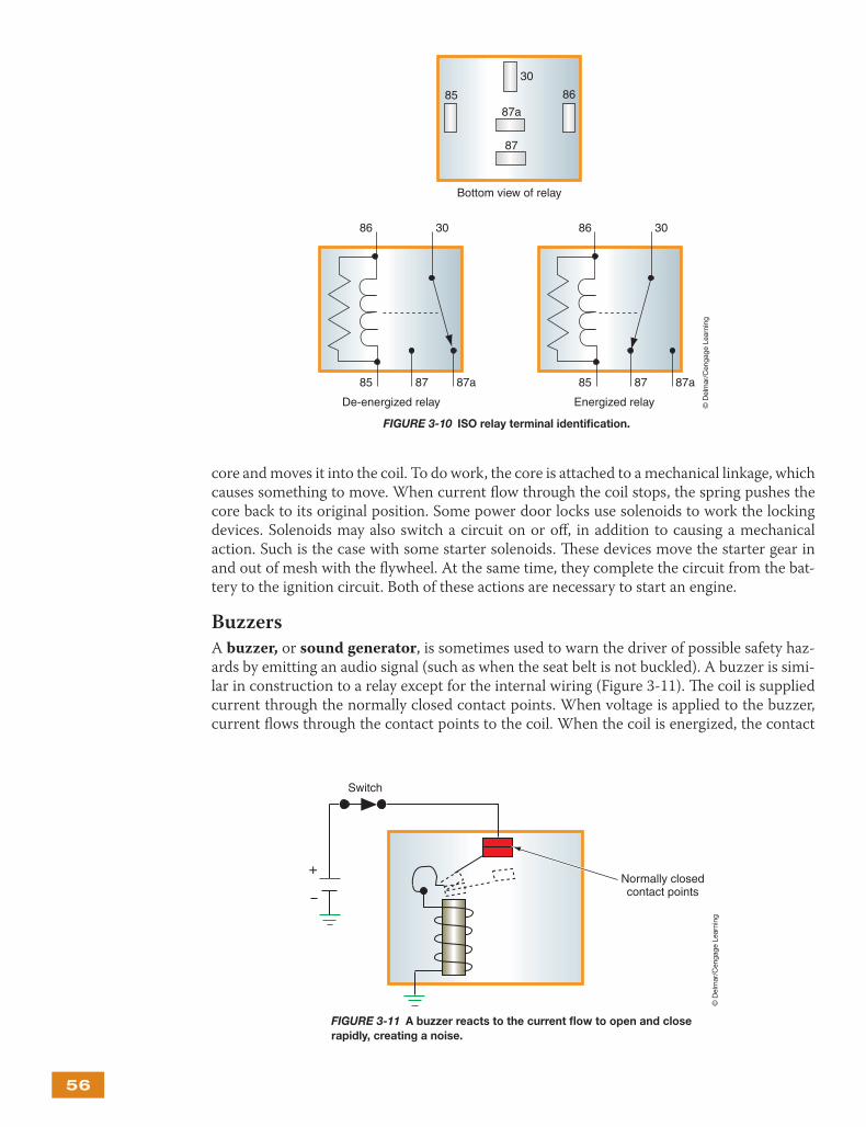
ISO Relays. ISO relays confi rm to the specifi cations of the International Standards Organization (ISO) for common size and terminal patterns (Figure 3-10). Th e terminals are identifi ed as 30, 87a, 87, 86, and 85. Terminal 30 is usually connected to battery voltage. Th is source voltage can be either switched (on or off by some type of switch) or connected directly to the battery. Terminal 87a is connected to terminal 30 when the relay is de- energized. Terminal 87 is connected to terminal 30 when the relay is energized. Terminal 86 is con-nected to battery voltage (switched or un-switched) to supply current to the electromagnet. Finally, terminal 85 provides ground for the electromagnet. Once again, the ground can be switched or unswitched.
Solenoids
A solenoid is an electromagnetic device and operates in the same way as a relay; however, a solenoid uses a movable iron core. Solenoids can do mechanical work, such as switching elec-trical, vacuum, and liquid circuits. Th e iron core inside the coil of the solenoid is spring loaded. When current fl ows through the coil, the magnetic fi eld created around the coil attracts the
+Battery
Ground
Fuse
Horn
Ground
Ground
Hornswitch
Relay
FIGURE 3-8 A relay can be used in the horn circuit to reduce the required
size of the conductors installed in the steering column.
© D
elm
ar/C
enga
ge L
earn
ing
FIGURE 3-9 Using a relay as a diverter to control Hi/Lo wiper operation.
The Hi/Lo relay diverts current to the different brushes of the wiper motor.
Ignitionvoltage
Hi speed Lo speed
Wiper motor
Hi/Lorelay
Wiperon/offrelay
Bodycontrolmodule
© D
elm
ar/C
enga
ge L
earn
ing
56
core and moves it into the coil. To do work, the core is attached to a mechanical linkage, which causes something to move. When current fl ow through the coil stops, the spring pushes the core back to its original position. Some power door locks use solenoids to work the locking devices. Solenoids may also switch a circuit on or off , in addition to causing a mechanical action. Such is the case with some starter solenoids. Th ese devices move the starter gear in and out of mesh with the fl ywheel. At the same time, they complete the circuit from the bat-tery to the ignition circuit. Both of these actions are necessary to start an engine.
Buzzers
A buzzer, or sound generator, is sometimes used to warn the driver of possible safety haz-ards by emitting an audio signal (such as when the seat belt is not buckled). A buzzer is simi-lar in construction to a relay except for the internal wiring (Figure 3-11). Th e coil is supplied current through the normally closed contact points. When voltage is applied to the buzzer, current fl ows through the contact points to the coil. When the coil is energized, the contact
86
86
85
85
87
87
30
30
87a
87a
86
85 87
30
87a
Bottom view of relay
De-energized relay Energized relay
FIGURE 3-10 ISO relay terminal identifi cation.
© D
elm
ar/C
enga
ge L
earn
ing
FIGURE 3-11 A buzzer reacts to the current fl ow to open and close
rapidly, creating a noise.
+Normally closedcontact points
Switch
© D
elm
ar/C
enga
ge L
earn
ing
57
arm is attracted to the magnetic fi eld. As soon as the contact arm is pulled down, the current fl ow to the coil is opened, and the magnetic fi eld is dissipated. Th e contact arm then closes again, and the circuit to the coil is closed. Th is opening and closing action occurs very rapidly. It is this movement that generates the vibrating signal.
Resistors
All circuits require resistance in order to operate. If the resistance performs a useful function, it is referred to as the load device. However, resistance can also be used to control current fl ow and as sensing devices for computer systems. Th ere are several types of resistors that may be used within a circuit. Th ese include fi xed resistors, stepped resistors, and variable resistors.
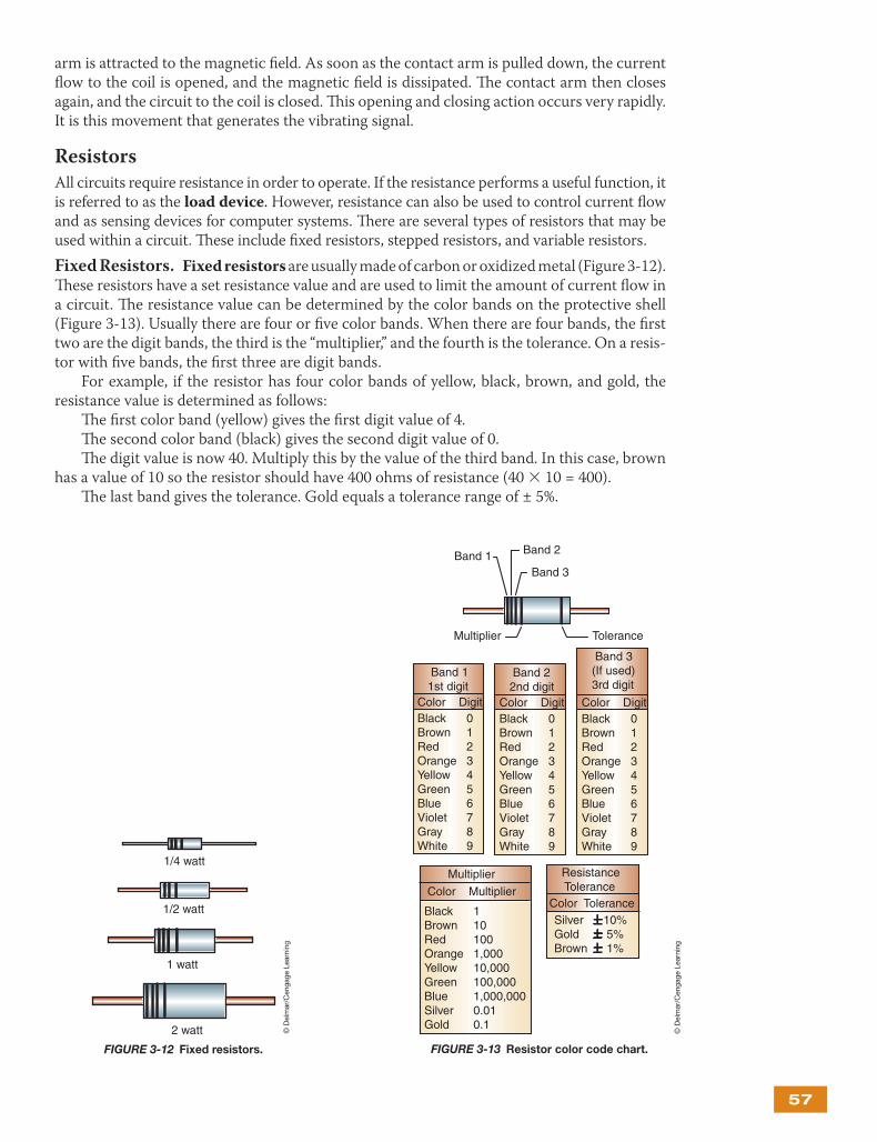
Fixed Resistors. Fixed resistors are usually made of carbon or oxidized metal (Figure 3-12). Th ese resistors have a set resistance value and are used to limit the amount of current fl ow in a circuit. Th e resistance value can be determined by the color bands on the protective shell (Figure 3-13). Usually there are four or fi ve color bands. When there are four bands, the fi rst two are the digit bands, the third is the “multiplier,” and the fourth is the tolerance. On a resis-tor with fi ve bands, the fi rst three are digit bands.
For example, if the resistor has four color bands of yellow, black, brown, and gold, the resistance value is determined as follows:
Th e fi rst color band (yellow) gives the fi rst digit value of 4.Th e second color band (black) gives the second digit value of 0.Th e digit value is now 40. Multiply this by the value of the third band. In this case, brown
has a value of 10 so the resistor should have 400 ohms of resistance (40 × 10 = 400).Th e last band gives the tolerance. Gold equals a tolerance range of ± 5%.
FIGURE 3-12 Fixed resistors.
1 watt
1/2 watt
1/4 watt
2 watt © D
elm
ar/C
enga
ge L
earn
ing
Band 1 Band 2
Band 3
Multiplier Tolerance
Band 11st digit
Color DigitBlack 0Brown 1Red 2Orange 3Yellow 4Green 5Blue 6Violet 7 Gray 8 White 9
Band 3(If used)3rd digit
Color DigitBlack 0Brown 1Red 2Orange 3Yellow 4Green 5Blue 6Violet 7 Gray 8 White 9
Band 22nd digit
Color DigitBlack 0Brown 1Red 2Orange 3Yellow 4Green 5Blue 6Violet 7 Gray 8 White 9
Multiplier
Color Multiplier
Black 1Brown 10 Red 100Orange 1,000Yellow 10,000Green 100,000Blue 1,000,000 Silver 0.01Gold 0.1
Resistance Tolerance
Color ToleranceSilver 10%Gold 5%Brown 1%
FIGURE 3-13 Resistor color code chart.
© D
elm
ar/C
enga
ge L
earn
ing
58
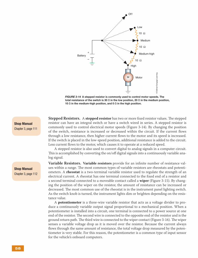
Stepped Resistors. A stepped resistor has two or more fi xed resistor values. Th e stepped resistor can have an integral switch or have a switch wired in series. A stepped resistor is commonly used to control electrical motor speeds (Figure 3-14). By changing the position of the switch, resistance is increased or decreased within the circuit. If the current fl ows through a low resistance, then higher current fl ows to the motor and its speed is increased. If the switch is placed in the low-speed position, additional resistance is added to the circuit. Less current fl ows to the motor, which causes it to operate at a reduced speed.
A stepped resistor is also used to convert digital to analog signals in a computer circuit. Th is is accomplished by converting the on/off digital signals into a continuously variable ana-log signal.
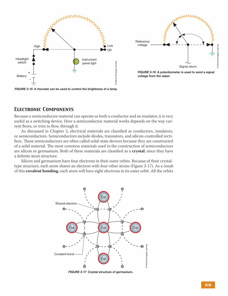
Variable Resistors. Variable resistors provide for an infi nite number of resistance val-ues within a range. Th e most common types of variable resistors are rheostats and potenti-ometers. A rheostat is a two-terminal variable resistor used to regulate the strength of an electrical current. A rheostat has one terminal connected to the fi xed end of a resistor and a second terminal connected to a moveable contact called a wiper (Figure 3-15). By chang-ing the position of the wiper on the resistor, the amount of resistance can be increased or decreased. Th e most common use of the rheostat is in the instrument panel lighting switch. As the switch knob is turned, the instrument lights dim or brighten depending on the resis-tance value.
A potentiometer is a three-wire variable resistor that acts as a voltage divider to pro-duce a continuously variable output signal proportional to a mechanical position. When a potentiometer is installed into a circuit, one terminal is connected to a power source at one end of the resistor. Th e second wire is connected to the opposite end of the resistor and is the ground return path. Th e third wire is connected to the wiper contact (Figure 3-16). Th e wiper senses a variable voltage drop as it is moved over the resistor. Because the current always fl ows through the same amount of resistance, the total voltage drop measured by the poten-tiometer is very stable. For this reason, the potentiometer is a common type of input sensor for the vehicle’s onboard computers.
Shop Manual
Chapter 3, page 111
Shop Manual
Chapter 3, page 112
FIGURE 3-14 A stepped resistor is commonly used to control motor speeds. The
total resistance of the switch is 30 Ω in the low position, 20 Ω in the medium position,
10 Ω in the medium-high position, and 0 Ω in the high position.
+Battery
Of f
M
Low
Medium
Medium-high
High
Motor
10 Ω
10 Ω
10 Ω
© D
elm
ar/C
enga
ge L
earn
ing
59
Electronic ComponentsBecause a semiconductor material can operate as both a conductor and an insulator, it is very useful as a switching device. How a semiconductor material works depends on the way cur-rent fl ows, or tries to fl ow, through it.
As discussed in Chapter 2, electrical materials are classifi ed as conductors, insulators, or semiconductors. Semiconductors include diodes, transistors, and silicon-controlled recti-fi ers. Th ese semiconductors are often called solid-state devices because they are constructed of a solid material. Th e most common materials used in the construction of semiconductors are silicon or germanium. Both of these materials are classifi ed as a crystal, since they have a defi nite atom structure.
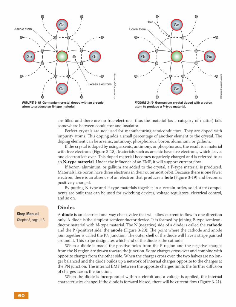
Silicon and germanium have four electrons in their outer orbits. Because of their crystal-type structure, each atom shares an electron with four other atoms (Figure 3-17). As a result of this covalent bonding, each atom will have eight electrons in its outer orbit. All the orbits
FIGURE 3-17 Crystal structure of germanium.
FIGURE 3-15 A rheostat can be used to control the brightness of a lamp.
+Battery
Off
LowHigh
Instrumentpanel light
Headlightswitch
© D
elm
ar/C
enga
ge L
earn
ing
FIGURE 3-16 A potentiometer is used to send a signal
voltage from the wiper.
Referencevoltage
Signal return © D
elm
ar/C
enga
ge L
earn
ing
Ge
Ge
Ge
GeGe
– –
– –
–
–
–
–
–
–
–
–
– –
– –
Shared electron
Covalent bond
© D
elm
ar/C
enga
ge L
earn
ing
60
are fi lled and there are no free electrons, thus the material (as a category of matter) falls somewhere between conductor and insulator.
Perfect crystals are not used for manufacturing semiconductors. Th ey are doped with impurity atoms. Th is doping adds a small percentage of another element to the crystal. Th e doping element can be arsenic, antimony, phosphorous, boron, aluminum, or gallium.
If the crystal is doped by using arsenic, antimony, or phosphorous, the result is a material with free electrons (Figure 3-18). Materials such as arsenic have fi ve electrons, which leaves one electron left over. Th is doped material becomes negatively charged and is referred to as an N-type material. Under the infl uence of an EMF, it will support current fl ow.
If boron, aluminum, or gallium are added to the crystal, a P-type material is produced. Materials like boron have three electrons in their outermost orbit. Because there is one fewer electron, there is an absence of an electron that produces a hole (Figure 3-19) and becomes positively charged.
By putting N-type and P-type materials together in a certain order, solid-state compo-nents are built that can be used for switching devices, voltage regulators, electrical control, and so on.
Diodes
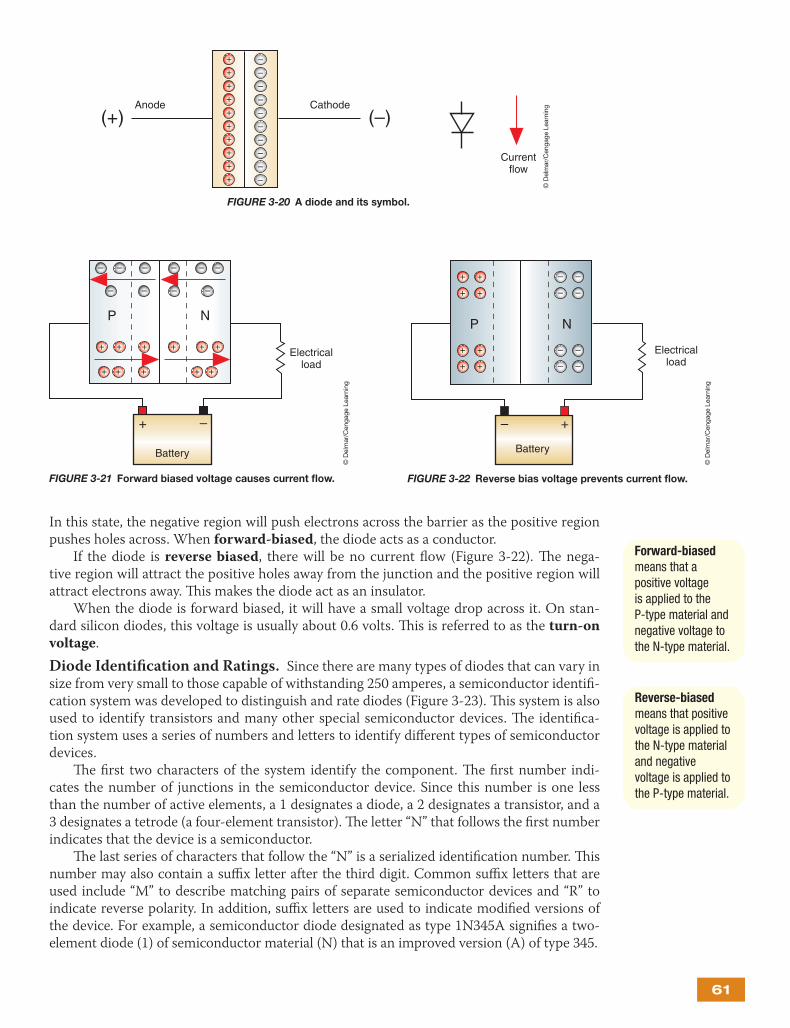
A diode is an electrical one-way check valve that will allow current to fl ow in one direction only. A diode is the simplest semiconductor device. It is formed by joining P-type semicon-ductor material with N-type material. Th e N (negative) side of a diode is called the cathode and the P (positive) side, the anode (Figure 3-20). Th e point where the cathode and anode join together is called the PN junction. Th e outer shell of the diode will have a stripe painted around it. Th is stripe designates which end of the diode is the cathode.
When a diode is made, the positive holes from the P region and the negative charges from the N region are drawn toward the junction. Some charges cross over and combine with opposite charges from the other side. When the charges cross over, the two halves are no lon-ger balanced and the diode builds up a network of internal charges opposite to the charges at the PN junction. Th e internal EMF between the opposite charges limits the further diff usion of charges across the junction.
When the diode is incorporated within a circuit and a voltage is applied, the internal characteristics change. If the diode is forward biased, there will be current fl ow (Figure 3-21).
Shop Manual
Chapter 3, page 113
Ge
Ge
GeGe
– –
– –
–
–
–
–
–
–
–
–
–
– –
– –
Excess electrons
Asenic atom
FIGURE 3-18 Germanium crystal doped with an arsenic
atom to produce an N-type material.
© D
elm
ar/C
enga
ge L
earn
ing
Ge
Ge
GeGe
– –
– –
–
–
–
–
–
–
–
–
– –
–
Boron atom
Hole
FIGURE 3-19 Germanium crystal doped with a boron
atom to produce a P-type material.
© D
elm
ar/C
enga
ge L
earn
ing
61
In this state, the negative region will push electrons across the barrier as the positive region pushes holes across. When forward-biased, the diode acts as a conductor.
If the diode is reverse biased, there will be no current fl ow (Figure 3-22). Th e nega-tive region will attract the positive holes away from the junction and the positive region will attract electrons away. Th is makes the diode act as an insulator.
When the diode is forward biased, it will have a small voltage drop across it. On stan-dard silicon diodes, this voltage is usually about 0.6 volts. Th is is referred to as the turn-on voltage.
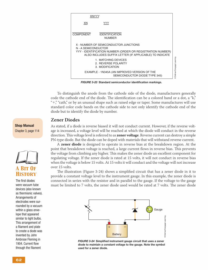
Diode Identifi cation and Ratings. Since there are many types of diodes that can vary in size from very small to those capable of withstanding 250 amperes, a semiconductor identifi -cation system was developed to distinguish and rate diodes (Figure 3-23). Th is system is also used to identify transistors and many other special semiconductor devices. Th e identifi ca-tion system uses a series of numbers and letters to identify diff erent types of semiconductor devices.
Th e fi rst two characters of the system identify the component. Th e fi rst number indi-cates the number of junctions in the semiconductor device. Since this number is one less than the number of active elements, a 1 designates a diode, a 2 designates a transistor, and a 3 designates a tetrode (a four-element transistor). Th e letter “N” that follows the fi rst number indicates that the device is a semiconductor.
Th e last series of characters that follow the “N” is a serialized identifi cation number. Th is number may also contain a suffi x letter after the third digit. Common suffi x letters that are used include “M” to describe matching pairs of separate semiconductor devices and “R” to indicate reverse polarity. In addition, suffi x letters are used to indicate modifi ed versions of the device. For example, a semiconductor diode designated as type 1N345A signifi es a two- element diode (1) of semiconductor material (N) that is an improved version (A) of type 345.
Forward-biased means that a positive voltage is applied to the P-type material and negative voltage to the N-type material.
Reverse-biased means that positive voltage is applied to the N-type material and negative voltage is applied to the P-type material.
Anode Cathode(+) (–)
Currentflow
––
++++++++
++
––––––––
FIGURE 3-20 A diode and its symbol.
© D
elm
ar/C
enga
ge L
earn
ing
Electricalload
+ –
Battery
N
–
+
– – – – –
– – – –
++ +++
++ + ++
P
FIGURE 3-21 Forward biased voltage causes current fl ow.
© D
elm
ar/C
enga
ge L
earn
ing
Electricalload
+–
Battery
NP
+ +
+ +
– –
– –
– –
– –
+ +
+ +
FIGURE 3-22 Reverse bias voltage prevents current fl ow.
© D
elm
ar/C
enga
ge L
earn
ing
62
To distinguish the anode from the cathode side of the diode, manufacturers generally code the cathode end of the diode. Th e identifi cation can be a colored band or a dot, a “k,” “+,” “cath,” or by an unusual shape such as raised edge or taper. Some manufactures will use standard color code bands on the cathode side to not only identify the cathode end of the diode but to identify the diode by number.
Zener Diodes
As stated, if a diode is reverse biased it will not conduct current. However, if the reverse volt-age is increased, a voltage level will be reached at which the diode will conduct in the reverse direction. Th is voltage level is referred to as zener voltage. Reverse current can destroy a simple PN-type diode. But the diode can be doped with materials that will withstand reverse current.
A zener diode is designed to operate in reverse bias at the breakdown region. At the point that breakdown voltage is reached, a large current fl ows in reverse bias. Th is prevents the voltage from climbing any higher. Th is makes the zener diode an excellent component for regulating voltage. If the zener diode is rated at 15 volts, it will not conduct in reverse bias when the voltage is below 15 volts. At 15 volts it will conduct and the voltage will not increase over 15 volts.
Th e illustration (Figure 3-24) shows a simplifi ed circuit that has a zener diode in it to provide a constant voltage level to the instrument gauge. In this example, the zener diode is connected in series with the resistor and in parallel to the gauge. If the voltage to the gauge must be limited to 7 volts, the zener diode used would be rated at 7 volts. Th e zener diode
A Bit Of HistoryThe fi rst diodes were vacuum tube devices (also known as thermionic valves). Arrangements of electrodes were sur-rounded by a vacuum within a glass enve-lope that appeared similar to light bulbs. This arrangement of a fi lament and plate to create a diode was invented by John Ambrose Fleming in 1904. Current fl ow through the fi lament
Shop Manual
Chapter 3, page 114
FIGURE 3-23 Standard semiconductor identifi cation markings.
XNYYY
XN
COMPONENT IDENTIFICATIONNUMBER
X - NUMBER OF SEMICONDUCTOR JUNCTIONSN - A SEMICONDUCTORYYY - IDENTIFICATION NUMBER (ORDER OR REGISTRATION NUMBER)
ALSO INCLUDES SUFFIX LETTER (IF APPLICABLE) TO INDICATE
1. MATCHING DEVICES2. REVERSE POLARITY3. MODIFICATION
EXAMPLE - 1N345A (AN IMPROVED VERSION OF THE SEMICONDUCTOR DIODE TYPE 345)
YYY
© D
elm
ar/C
enga
ge L
earn
ing
+ –
Battery
Gauge
FIGURE 3-24 Simplifi ed instrument gauge circuit that uses a zener
diode to maintain a constant voltage to the gauge. Note the symbol
used for a zener diode.
© D
elm
ar/C
enga
ge L
earn
ing
63
maintains a constant voltage drop, and the total voltage drop in a series circuit must equal the amount of source voltage, thus voltage that is greater than the zener voltage must be dropped over the resistor. Even though source voltage may vary (as a normal result of the charging system), causing diff erent currents to fl ow through the resistor and zener diode, the voltage that the zener diode drops remains the same.
Th e zener breaks down when system voltage reaches 7 volts. At this point, the zener diode conducts reverse current, causing an additional voltage drop across the resistor. Th e amount of voltage to the instrument gauge will remain at 7 volts because the zener diode “makes” the resistor drop the additional voltage to maintain this limit.
Here we see the diff erence between the standard diode and the zener diode. When the zener diode is reverse biased, the zener holds the available voltage to a specifi c value.
Avalanche Diodes
Avalanche diodes are diodes that conduct in the reverse direction when the reverse-bias voltage exceeds the breakdown voltage, similar to zener diodes in operation. However, break-down is done by the avalanche eff ect. Th is occurs when the reverse electric fi eld moves across the PN junction and causes a wave of ionization (like an avalanche), leading to a large current. Avalanche diodes are designed to break down at a well-defi ned reverse voltage without being destroyed. Th e reverse breakdown voltage is about 6.2 volts or higher. Avalanche diodes are commonly used in automobile AC generators (alternators).
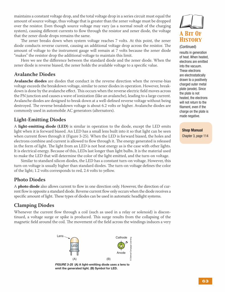
Light-Emitting Diodes
A light-emitting diode (LED) is similar in operation to the diode, except the LED emits light when it is forward biased. An LED has a small lens built into it so that light can be seen when current fl ows through it (Figure 3-25). When the LED is forward biased, the holes and electrons combine and current is allowed to fl ow through it. Th e energy generated is released in the form of light. Th e light from an LED is not heat energy as is the case with other lights. It is electrical energy. Because of this, LEDs last longer than light bulbs. It is the material used to make the LED that will determine the color of the light emitted, and the turn-on voltage.
Similar to standard silicon diodes, the LED has a constant turn-on voltage. However, this turn-on voltage is usually higher than standard diodes. Th e turn-on voltage defi nes the color of the light; 1.2 volts corresponds to red, 2.4 volts to yellow.
Photo Diodes
A photo diode also allows current to fl ow in one direction only. However, the direction of cur-rent fl ow is opposite a standard diode. Reverse current fl ow only occurs when the diode receives a specifi c amount of light. Th ese types of diodes can be used in automatic headlight systems.
Clamping Diodes
Whenever the current fl ow through a coil (such as used in a relay or solenoid) is discon-tinued, a voltage surge or spike is produced. Th is surge results from the collapsing of the magnetic fi eld around the coil. Th e movement of the fi eld across the windings induces a very
A Bit Of History(Continued)results in generation of heat. When heated, electrons are emitted into the vacuum. These electrons are electrostatically drawn to a positively charged outer metal plate (anode). Since the plate is not heated, the electrons will not return to the fi lament, even if the charge on the plate is made negative.
Shop Manual
Chapter 3, page 114
FIGURE 3-25 (A) A light-emitting diode uses a lens to
emit the generated light. (B) Symbol for LED.
(A)
Cathode
LED
Lens
(B)
Anode
© D
elm
ar/C
enga
ge L
earn
ing
64
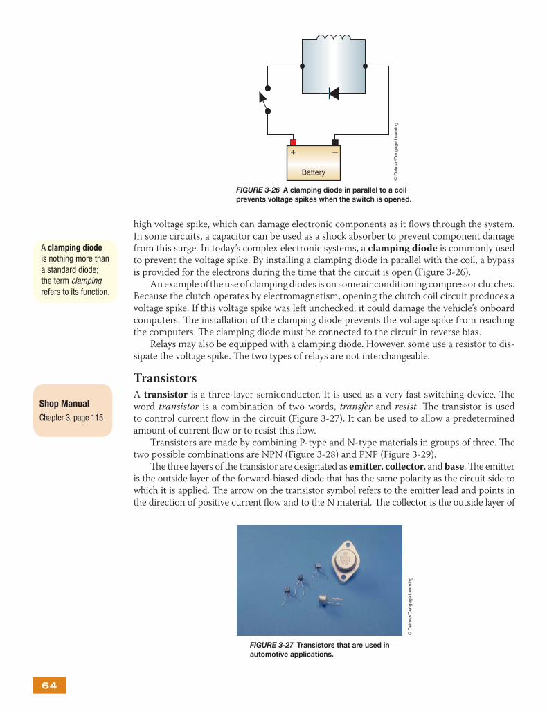
high voltage spike, which can damage electronic components as it fl ows through the system. In some circuits, a capacitor can be used as a shock absorber to prevent component damage from this surge. In today’s complex electronic systems, a clamping diode is commonly used to prevent the voltage spike. By installing a clamping diode in parallel with the coil, a bypass is provided for the electrons during the time that the circuit is open (Figure 3-26).
An example of the use of clamping diodes is on some air conditioning compressor clutches. Because the clutch operates by electromagnetism, opening the clutch coil circuit produces a voltage spike. If this voltage spike was left unchecked, it could damage the vehicle’s onboard computers. Th e installation of the clamping diode prevents the voltage spike from reaching the computers. Th e clamping diode must be connected to the circuit in reverse bias.
Relays may also be equipped with a clamping diode. However, some use a resistor to dis-sipate the voltage spike. Th e two types of relays are not interchangeable.
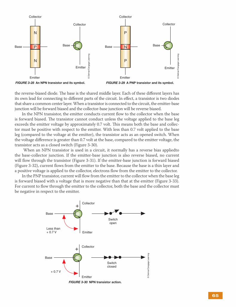
Transistors
A transistor is a three-layer semiconductor. It is used as a very fast switching device. Th e word transistor is a combination of two words, transfer and resist. Th e transistor is used to control current fl ow in the circuit (Figure 3-27). It can be used to allow a predetermined amount of current fl ow or to resist this fl ow.
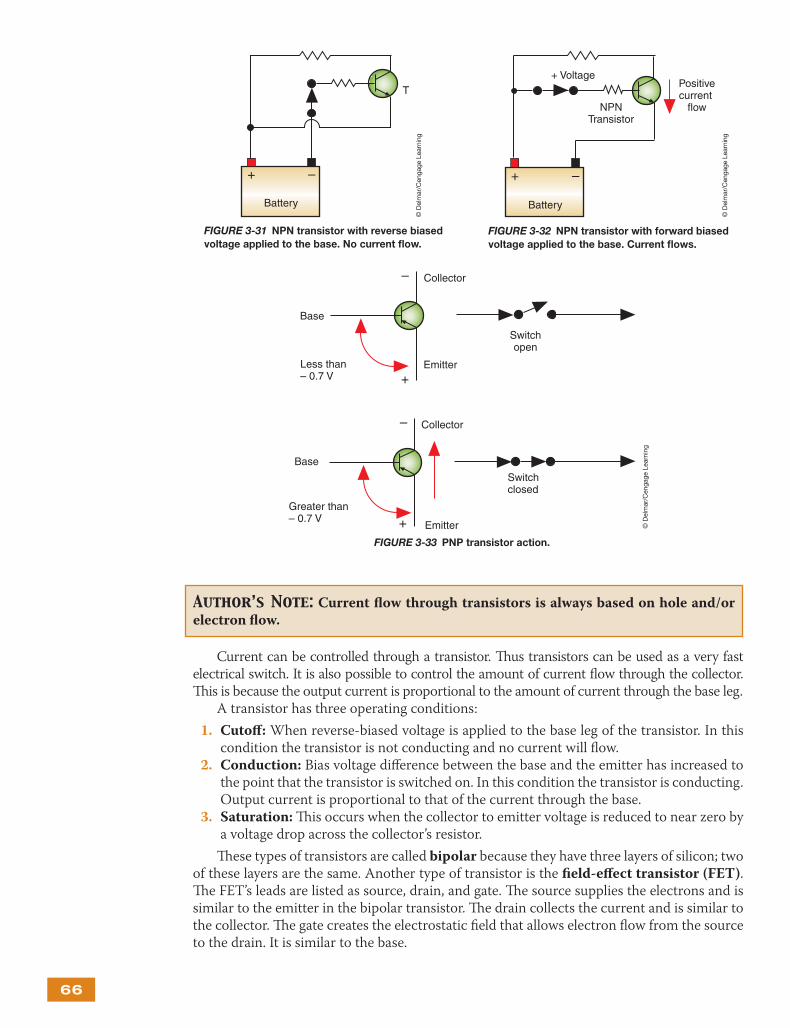
Transistors are made by combining P-type and N-type materials in groups of three. Th e two possible combinations are NPN (Figure 3-28) and PNP (Figure 3-29).
Th e three layers of the transistor are designated as emitter, collector, and base. Th e emitter is the outside layer of the forward-biased diode that has the same polarity as the circuit side to which it is applied. Th e arrow on the transistor symbol refers to the emitter lead and points in the direction of positive current fl ow and to the N material. Th e collector is the outside layer of
A clamping diode is nothing more than a standard diode; the term clamping refers to its function.
Shop Manual
Chapter 3, page 115
+ –
Battery
FIGURE 3-26 A clamping diode in parallel to a coil
prevents voltage spikes when the switch is opened.
© D
elm
ar/C
enga
ge L
earn
ing
FIGURE 3-27 Transistors that are used in
automotive applications.
© D
elm
ar/C
enga
ge L
earn
ing
65
the reverse-biased diode. Th e base is the shared middle layer. Each of these diff erent layers has its own lead for connecting to diff erent parts of the circuit. In eff ect, a transistor is two diodes that share a common center layer. When a transistor is connected to the circuit, the emitter-base junction will be forward biased and the collector-base junction will be reverse biased.
In the NPN transistor, the emitter conducts current fl ow to the collector when the base is forward biased. Th e transistor cannot conduct unless the voltage applied to the base leg exceeds the emitter voltage by approximately 0.7 volt. Th is means both the base and collec-tor must be positive with respect to the emitter. With less than 0.7 volt applied to the base leg (compared to the voltage at the emitter), the transistor acts as an opened switch. When the voltage diff erence is greater than 0.7 volt at the base, compared to the emitter voltage, the transistor acts as a closed switch (Figure 3-30).
When an NPN transistor is used in a circuit, it normally has a reverse bias appliedto the base-collector junction. If the emitter-base junction is also reverse biased, no current will fl ow through the transistor (Figure 3-31). If the emitter-base junction is forward biased (Figure 3-32), current fl ows from the emitter to the base. Because the base is a thin layer and a positive voltage is applied to the collector, electrons fl ow from the emitter to the collector.
In the PNP transistor, current will fl ow from the emitter to the collector when the base leg is forward biased with a voltage that is more negative than that at the emitter (Figure 3-33). For current to fl ow through the emitter to the collector, both the base and the collector must be negative in respect to the emitter.
© D
elm
ar/C
enga
ge L
earn
ing
N
P
N
Collector
Base
Emitter
Base
Collector
Emitter
FIGURE 3-28 An NPN transistor and its symbol. FIGURE 3-29 A PNP transistor and its symbol.
Base
Collector
Emitter
P
N
P
Collector
Base
Emitter © D
elm
ar/C
enga
ge L
earn
ing
Base
Collector
Emitter
Switchopen
Less than+ 0.7 V
+
Base
Collector
Emitter
Switchclosed
+ 0.7 V
+
FIGURE 3-30 NPN transistor action.
© D
elm
ar/C
enga
ge L
earn
ing
66
Current can be controlled through a transistor. Th us transistors can be used as a very fast electrical switch. It is also possible to control the amount of current fl ow through the collector. Th is is because the output current is proportional to the amount of current through the base leg.
A transistor has three operating conditions:
1. Cutoff : When reverse-biased voltage is applied to the base leg of the transistor. In this condition the transistor is not conducting and no current will fl ow.
2. Conduction: Bias voltage diff erence between the base and the emitter has increased to the point that the transistor is switched on. In this condition the transistor is conducting. Output current is proportional to that of the current through the base.
3. Saturation: Th is occurs when the collector to emitter voltage is reduced to near zero by a voltage drop across the collector’s resistor.
Th ese types of transistors are called bipolar because they have three layers of silicon; two of these layers are the same. Another type of transistor is the fi eld-eff ect transistor (FET). Th e FET’s leads are listed as source, drain, and gate. Th e source supplies the electrons and is similar to the emitter in the bipolar transistor. Th e drain collects the current and is similar to the collector. Th e gate creates the electrostatic fi eld that allows electron fl ow from the source to the drain. It is similar to the base.
Author’s Note: Current fl ow through transistors is always based on hole and/or electron fl ow.
Base
Collector
Emitter
Switchopen
Less than– 0.7 V
–
Base
Collector
Emitter
Switchclosed
–
+
Greater than– 0.7 V +
FIGURE 3-33 PNP transistor action.
© D
elm
ar/C
enga
ge L
earn
ing
+ –
Battery
+ Voltage
NPNTransistor
Positivecurrent
flow
FIGURE 3-32 NPN transistor with forward biased
voltage applied to the base. Current fl ows.
© D
elm
ar/C
enga
ge L
earn
ing
+ –
Battery
T
FIGURE 3-31 NPN transistor with reverse biased
voltage applied to the base. No current fl ow.
© D
elm
ar/C
enga
ge L
earn
ing
67
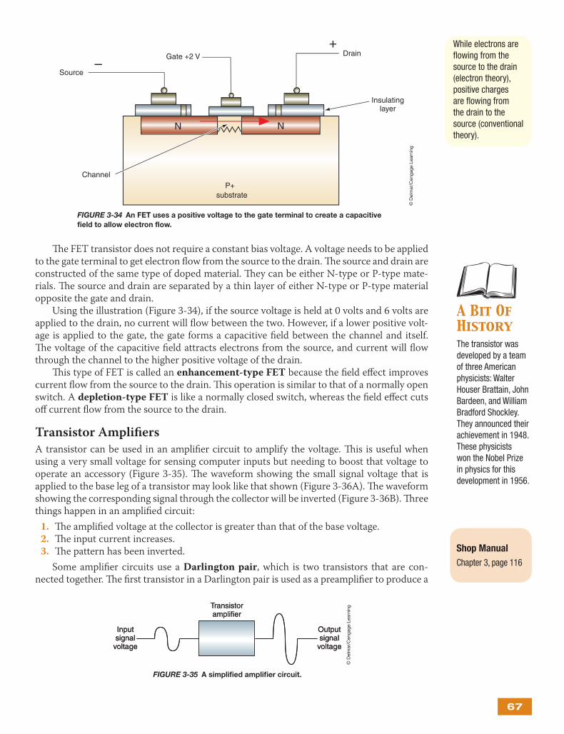
Th e FET transistor does not require a constant bias voltage. A voltage needs to be applied to the gate terminal to get electron fl ow from the source to the drain. Th e source and drain are constructed of the same type of doped material. Th ey can be either N-type or P-type mate-rials. Th e source and drain are separated by a thin layer of either N-type or P-type material opposite the gate and drain.
Using the illustration (Figure 3-34), if the source voltage is held at 0 volts and 6 volts are applied to the drain, no current will fl ow between the two. However, if a lower positive volt-age is applied to the gate, the gate forms a capacitive fi eld between the channel and itself. Th e voltage of the capacitive fi eld attracts electrons from the source, and current will fl ow through the channel to the higher positive voltage of the drain.
Th is type of FET is called an enhancement-type FET because the fi eld eff ect improves current fl ow from the source to the drain. Th is operation is similar to that of a normally open switch. A depletion-type FET is like a normally closed switch, whereas the fi eld eff ect cuts off current fl ow from the source to the drain.
Transistor Amplifi ers
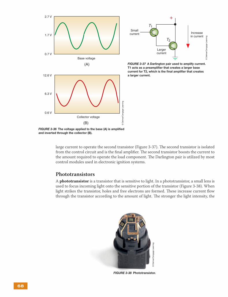
A transistor can be used in an amplifi er circuit to amplify the voltage. Th is is useful when using a very small voltage for sensing computer inputs but needing to boost that voltage to operate an accessory (Figure 3-35). Th e waveform showing the small signal voltage that is applied to the base leg of a transistor may look like that shown (Figure 3-36A). Th e waveform showing the corresponding signal through the collector will be inverted (Figure 3-36B). Th ree things happen in an amplifi ed circuit:
1. Th e amplifi ed voltage at the collector is greater than that of the base voltage. 2. Th e input current increases. 3. Th e pattern has been inverted.
Some amplifi er circuits use a Darlington pair, which is two transistors that are con-nected together. Th e fi rst transistor in a Darlington pair is used as a preamplifi er to produce a
A Bit Of HistoryThe transistor was developed by a team of three American physicists: Walter Houser Brattain, John Bardeen, and William Bradford Shockley. They announced their achievement in 1948. These physicists won the Nobel Prize in physics for this development in 1956.
Shop Manual
Chapter 3, page 116
While electrons are fl owing from the source to the drain (electron theory), positive charges are fl owing from the drain to the source (conventional theory).
FIGURE 3-34 An FET uses a positive voltage to the gate terminal to create a capacitive
fi eld to allow electron fl ow.
Channel
N N
P+substrate
Source
Gate +2 V Drain
Insulatinglayer
–
+
© D
elm
ar/C
enga
ge L
earn
ing
Inputsignal
voltage
Transistoramplifier
Outputsignal
voltage
Inputsignal
voltage
Transistoramplifier
Outputsignal
voltage
FIGURE 3-35 A simplifi ed amplifi er circuit.
© D
elm
ar/C
enga
ge L
earn
ing
68
large current to operate the second transistor (Figure 3-37). Th e second transistor is isolated from the control circuit and is the fi nal amplifi er. Th e second transistor boosts the current to the amount required to operate the load component. Th e Darlington pair is utilized by most control modules used in electronic ignition systems.
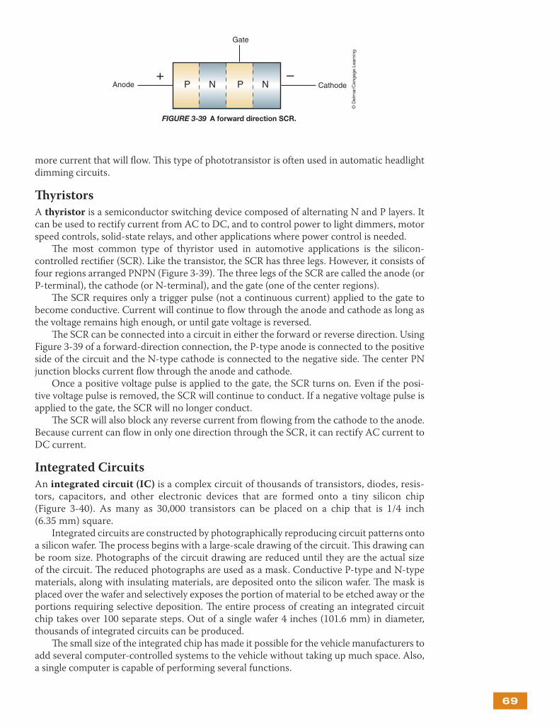
Phototransistors
A phototransistor is a transistor that is sensitive to light. In a phototransistor, a small lens is used to focus incoming light onto the sensitive portion of the transistor (Figure 3-38). When light strikes the transistor, holes and free electrons are formed. Th ese increase current fl ow through the transistor according to the amount of light. Th e stronger the light intensity, the
2.7 V
1.7 V
0.7 V
(A)
12.6 V
6.3 V
0.6 V
(B)
Base voltage
Collector voltage
FIGURE 3-36 The voltage applied to the base (A) is amplifi ed
and inverted through the collector (B).
© D
elm
ar/C
enga
ge L
earn
ing
+T1
T2
Smallcurrent
Largercurrent
Increasein current
FIGURE 3-37 A Darlington pair used to amplify current.
T1 acts as a preamplifi er that creates a larger base
current for T2, which is the fi nal amplifi er that creates
a larger current.
© D
elm
ar/C
enga
ge L
earn
ing
FIGURE 3-38 Phototransistor.
© D
elm
ar/C
enga
ge L
earn
ing
69
more current that will fl ow. Th is type of phototransistor is often used in automatic headlight dimming circuits.
Th yristors
A thyristor is a semiconductor switching device composed of alternating N and P layers. It can be used to rectify current from AC to DC, and to control power to light dimmers, motor speed controls, solid-state relays, and other applications where power control is needed.
Th e most common type of thyristor used in automotive applications is the silicon- controlled rectifi er (SCR). Like the transistor, the SCR has three legs. However, it consists of four regions arranged PNPN (Figure 3-39). Th e three legs of the SCR are called the anode (or P-terminal), the cathode (or N-terminal), and the gate (one of the center regions).
Th e SCR requires only a trigger pulse (not a continuous current) applied to the gate to become conductive. Current will continue to fl ow through the anode and cathode as long as the voltage remains high enough, or until gate voltage is reversed.
Th e SCR can be connected into a circuit in either the forward or reverse direction. Using Figure 3-39 of a forward-direction connection, the P-type anode is connected to the positive side of the circuit and the N-type cathode is connected to the negative side. Th e center PN junction blocks current fl ow through the anode and cathode.
Once a positive voltage pulse is applied to the gate, the SCR turns on. Even if the posi-tive voltage pulse is removed, the SCR will continue to conduct. If a negative voltage pulse is applied to the gate, the SCR will no longer conduct.
Th e SCR will also block any reverse current from fl owing from the cathode to the anode. Because current can fl ow in only one direction through the SCR, it can rectify AC current to DC current.
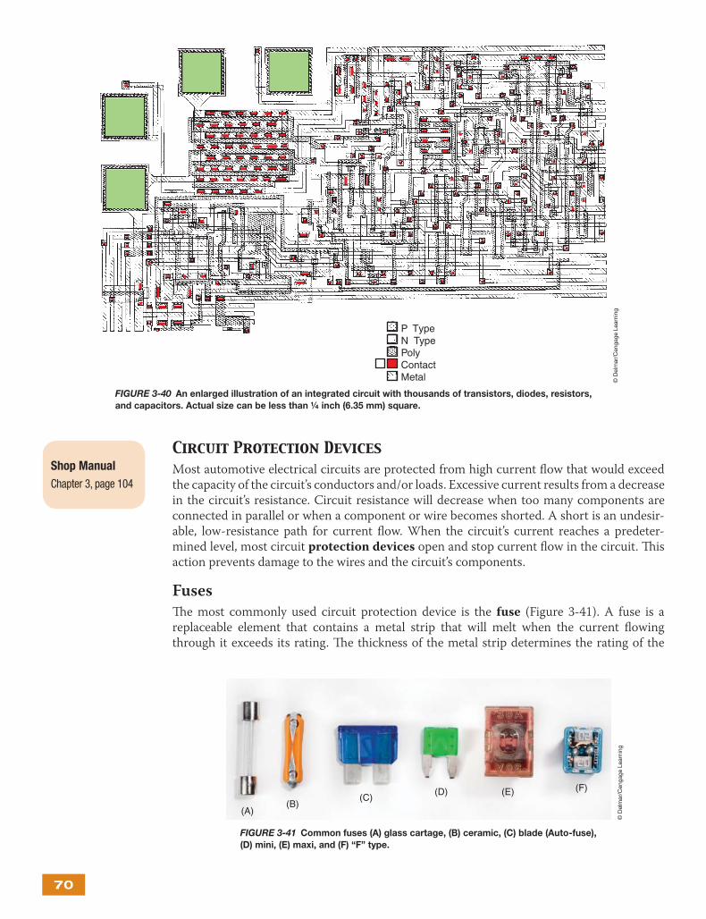
Integrated Circuits
An integrated circuit (IC) is a complex circuit of thousands of transistors, diodes, resis-tors, capacitors, and other electronic devices that are formed onto a tiny silicon chip (Figure 3-40). As many as 30,000 transistors can be placed on a chip that is 1/4 inch (6.35 mm) square.
Integrated circuits are constructed by photographically reproducing circuit patterns onto a silicon wafer. Th e process begins with a large-scale drawing of the circuit. Th is drawing can be room size. Photographs of the circuit drawing are reduced until they are the actual size of the circuit. Th e reduced photographs are used as a mask. Conductive P-type and N-type materials, along with insulating materials, are deposited onto the silicon wafer. Th e mask is placed over the wafer and selectively exposes the portion of material to be etched away or the portions requiring selective deposition. Th e entire process of creating an integrated circuit chip takes over 100 separate steps. Out of a single wafer 4 inches (101.6 mm) in diameter, thousands of integrated circuits can be produced.
Th e small size of the integrated chip has made it possible for the vehicle manufacturers to add several computer-controlled systems to the vehicle without taking up much space. Also, a single computer is capable of performing several functions.
Anode
Gate
Cathode+ –
P N P N
FIGURE 3-39 A forward direction SCR.
© D
elm
ar/C
enga
ge L
earn
ing
70
Circuit Protection DevicesMost automotive electrical circuits are protected from high current fl ow that would exceed the capacity of the circuit’s conductors and/or loads. Excessive current results from a decrease in the circuit’s resistance. Circuit resistance will decrease when too many components are connected in parallel or when a component or wire becomes shorted. A short is an undesir-able, low-resistance path for current fl ow. When the circuit’s current reaches a predeter-mined level, most circuit protection devices open and stop current fl ow in the circuit. Th is action prevents damage to the wires and the circuit’s components.
Fuses
Th e most commonly used circuit protection device is the fuse (Figure 3-41). A fuse is a replaceable element that contains a metal strip that will melt when the current fl owing through it exceeds its rating. Th e thickness of the metal strip determines the rating of the
P TypeN TypePolyContactMetal
FIGURE 3-40 An enlarged illustration of an integrated circuit with thousands of transistors, diodes, resistors,
and capacitors. Actual size can be less than ¼ inch (6.35 mm) square.
Shop Manual
Chapter 3, page 104
(A)(B)
(C)(D) (E) (F)
FIGURE 3-41 Common fuses (A) glass cartage, (B) ceramic, (C) blade (Auto-fuse),
(D) mini, (E) maxi, and (F) “F” type.
© D
elm
ar/C
enga
ge L
earn
ing
© D
elm
ar/C
enga
ge L
earn
ing
71
fuse. When the metal strip melts, excessive current is indicated. Th e cause of the overload must be found and repaired; then a new fuse of the same rating should be installed. Th e most commonly used automotive fuses are rated from 3 to 30 amps.
Th ere are three basic types of fuses: glass or ceramic fuses, blade-type fuses, and bullet or cartridge fuses. Glass and ceramic fuses are found mostly on older vehicles. Sometimes, however, you can fi nd them in a special holder connected in series with a circuit. Glass fuses are small glass cylinders with metal caps. Th e metal strip connects the two caps. Th e rating of the fuse is normally marked on one of the caps.
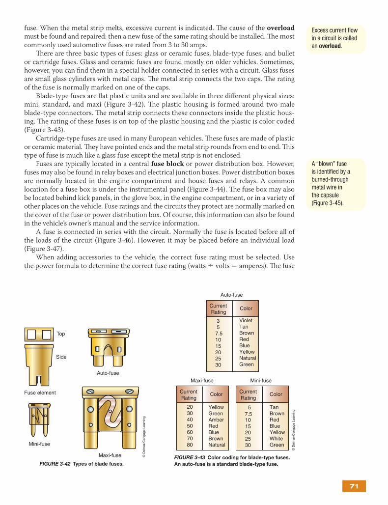
Blade-type fuses are fl at plastic units and are available in three diff erent physical sizes: mini, standard, and maxi (Figure 3-42). Th e plastic housing is formed around two male blade-type connectors. Th e metal strip connects these connectors inside the plastic hous-ing. Th e rating of these fuses is on top of the plastic housing and the plastic is color coded (Figure 3-43).
Cartridge-type fuses are used in many European vehicles. Th ese fuses are made of plastic or ceramic material. Th ey have pointed ends and the metal strip rounds from end to end. Th is type of fuse is much like a glass fuse except the metal strip is not enclosed.
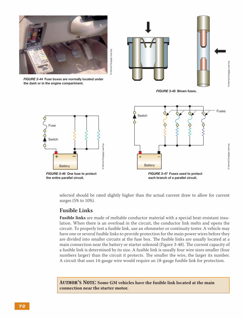
Fuses are typically located in a central fuse block or power distribution box. However, fuses may also be found in relay boxes and electrical junction boxes. Power distribution boxes are normally located in the engine compartment and house fuses and relays. A common location for a fuse box is under the instrumental panel (Figure 3-44). Th e fuse box may also be located behind kick panels, in the glove box, in the engine compartment, or in a variety of other places on the vehicle. Fuse ratings and the circuits they protect are normally marked on the cover of the fuse or power distribution box. Of course, this information can also be found in the vehicle’s owner’s manual and the service information.
A fuse is connected in series with the circuit. Normally the fuse is located before all of the loads of the circuit (Figure 3-46). However, it may be placed before an individual load (Figure 3-47).
When adding accessories to the vehicle, the correct fuse rating must be selected. Use the power formula to determine the correct fuse rating (watts ÷ volts = amperes). Th e fuse
A “blown” fuse is identifi ed by a burned-through metal wire in the capsule (Figure 3-45).
Excess current fl ow in a circuit is called an overload.
Auto-fuse
Current Rating
Color
3 57.51015202530
VioletTanBrownRedBlueYellowNaturalGreen
Maxi-fuse
Current Rating
Color
20 30 40 50 60 70 80
YellowGreenAmberRedBlueBrownNatural
Mini-fuse
Current Rating
Color
5
1015202530
7.5TanBrownRedBlueYellowWhiteGreen
FIGURE 3-43 Color coding for blade-type fuses.
An auto-fuse is a standard blade-type fuse.
Fuse element
Top
Side
Auto-fuse
Mini-fuse
Maxi-fuse
FIGURE 3-42 Types of blade fuses.
© D
elm
ar/C
enga
ge L
earn
ing
© D
elm
ar/C
enga
ge L
earn
ing
72
selected should be rated slightly higher than the actual current draw to allow for current surges (5% to 10%).
Fusible Links
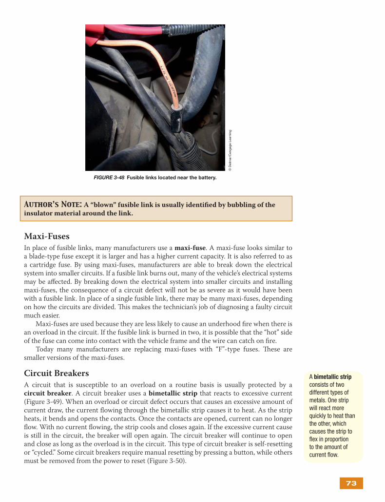
Fusible links are made of meltable conductor material with a special heat-resistant insu-lation. When there is an overload in the circuit, the conductor link melts and opens the circuit. To properly test a fusible link, use an ohmmeter or continuity tester. A vehicle may have one or several fusible links to provide protection for the main power wires before they are divided into smaller circuits at the fuse box. Th e fusible links are usually located at a main connection near the battery or starter solenoid (Figure 3-48). Th e current capacity of a fusible link is determined by its size. A fusible link is usually four wire sizes smaller (four numbers larger) than the circuit it protects. Th e smaller the wire, the larger its number. A circuit that uses 14-gauge wire would require an 18-gauge fusible link for protection.
Author’s Note: Some GM vehicles have the fusible link located at the main connection near the starter motor.
FIGURE 3-44 Fuse boxes are normally located under
the dash or in the engine compartment.
© D
elm
ar/C
enga
ge L
earn
ing
FIGURE 3-45 Blown fuses.
© D
elm
ar/C
enga
ge L
earn
ing
FIGURE 3-46 One fuse to protect
the entire parallel circuit.
+ –
Fuse
Battery
Switch
© D
elm
ar/C
enga
ge L
earn
ing
Fuses
+ –
Battery
Switch
FIGURE 3-47 Fuses used to protect
each branch of a parallel circuit.
© D
elm
ar/C
enga
ge L
earn
ing
73
Maxi-Fuses
In place of fusible links, many manufacturers use a maxi-fuse. A maxi-fuse looks similar to a blade-type fuse except it is larger and has a higher current capacity. It is also referred to as a cartridge fuse. By using maxi-fuses, manufacturers are able to break down the electrical system into smaller circuits. If a fusible link burns out, many of the vehicle’s electrical systems may be aff ected. By breaking down the electrical system into smaller circuits and installing maxi-fuses, the consequence of a circuit defect will not be as severe as it would have been with a fusible link. In place of a single fusible link, there may be many maxi-fuses, depending on how the circuits are divided. Th is makes the technician’s job of diagnosing a faulty circuit much easier.
Maxi-fuses are used because they are less likely to cause an underhood fi re when there is an overload in the circuit. If the fusible link is burned in two, it is possible that the “hot” side of the fuse can come into contact with the vehicle frame and the wire can catch on fi re.
Today many manufacturers are replacing maxi-fuses with “F”-type fuses. Th ese are smaller versions of the maxi-fuses.
Circuit Breakers
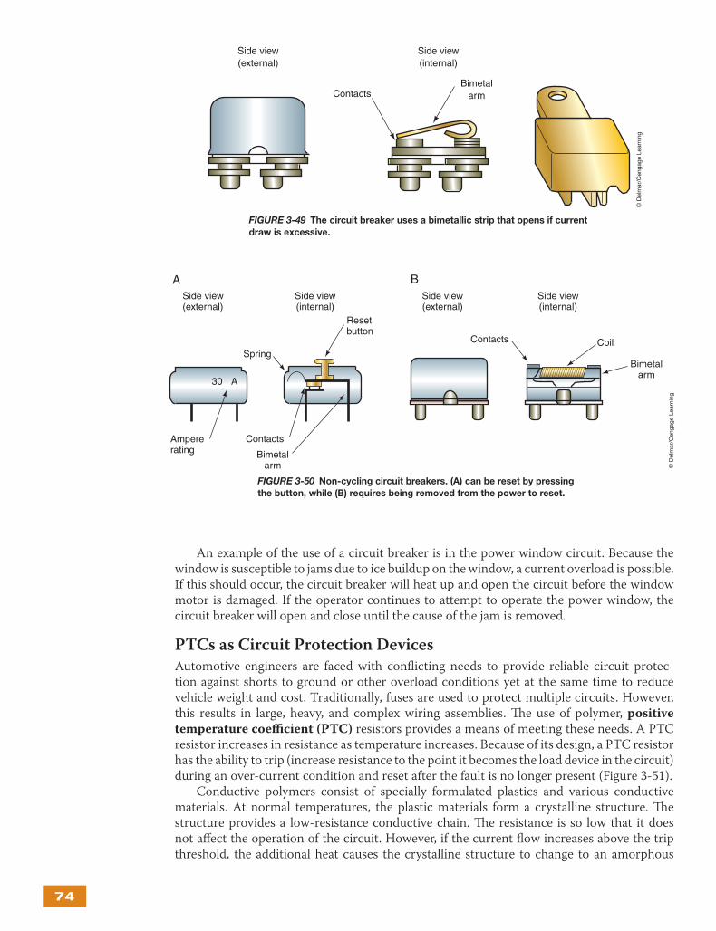
A circuit that is susceptible to an overload on a routine basis is usually protected by a circuit breaker. A circuit breaker uses a bimetallic strip that reacts to excessive current (Figure 3-49). When an overload or circuit defect occurs that causes an excessive amount of current draw, the current fl owing through the bimetallic strip causes it to heat. As the strip heats, it bends and opens the contacts. Once the contacts are opened, current can no longer fl ow. With no current fl owing, the strip cools and closes again. If the excessive current cause is still in the circuit, the breaker will open again. Th e circuit breaker will continue to open and close as long as the overload is in the circuit. Th is type of circuit breaker is self-resetting or “cycled.” Some circuit breakers require manual resetting by pressing a button, while others must be removed from the power to reset (Figure 3-50).
Author’s Note: A “blown” fusible link is usually identifi ed by bubbling of the insulator material around the link.
A bimetallic strip consists of two diffe rent types of metals. One strip will react more quickly to heat than the other, which causes the strip to fl ex in proportion to the amount of current fl ow.
FIGURE 3-48 Fusible links located near the battery.
© D
elm
ar/C
enga
ge L
earn
ing
74
An example of the use of a circuit breaker is in the power window circuit. Because the window is susceptible to jams due to ice buildup on the window, a current overload is possible. If this should occur, the circuit breaker will heat up and open the circuit before the window motor is damaged. If the operator continues to attempt to operate the power window, the circuit breaker will open and close until the cause of the jam is removed.
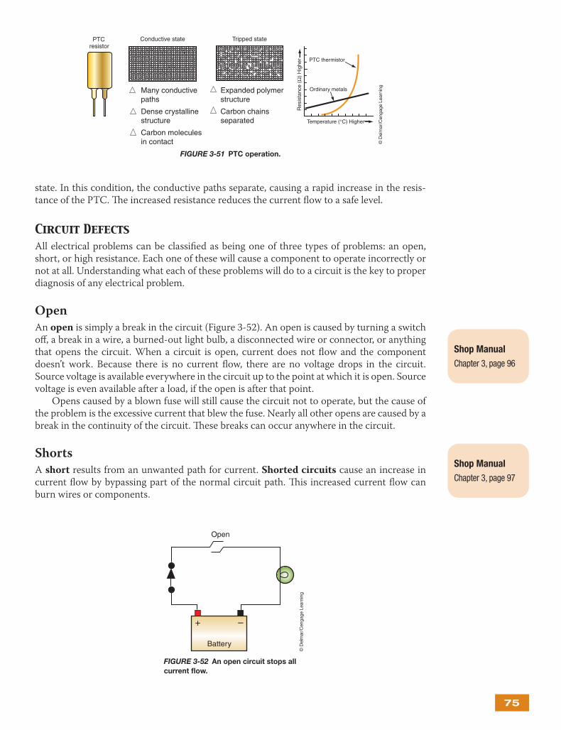
PTCs as Circuit Protection Devices
Automotive engineers are faced with confl icting needs to provide reliable circuit protec-tion against shorts to ground or other overload conditions yet at the same time to reduce vehicle weight and cost. Traditionally, fuses are used to protect multiple circuits. However, this results in large, heavy, and complex wiring assemblies. Th e use of polymer, positive temperature coeffi cient (PTC) resistors provides a means of meeting these needs. A PTC resistor increases in resistance as temperature increases. Because of its design, a PTC resistor has the ability to trip (increase resistance to the point it becomes the load device in the circuit) during an over-current condition and reset after the fault is no longer present (Figure 3-51).
Conductive polymers consist of specially formulated plastics and various conductive materials. At normal temperatures, the plastic materials form a crystalline structure. Th e structure provides a low-resistance conductive chain. Th e resistance is so low that it does not aff ect the operation of the circuit. However, if the current fl ow increases above the trip threshold, the additional heat causes the crystalline structure to change to an amorphous
ContactsBimetal
arm
Side view(external)
Side view(internal)
FIGURE 3-49 The circuit breaker uses a bimetallic strip that opens if current
draw is excessive.
© D
elm
ar/C
enga
ge L
earn
ing
Side view(external)
Side view(internal)
Contacts Coil
Bimetalarm
30 A
Contacts
Bimetalarm
Ampererating
Side view(external)
Side view(internal)
BA
Spring
Resetbutton
FIGURE 3-50 Non-cycling circuit breakers. (A) can be reset by pressing
the button, while (B) requires being removed from the power to reset.
© D
elm
ar/C
enga
ge L
earn
ing
75
state. In this condition, the conductive paths separate, causing a rapid increase in the resis-tance of the PTC. Th e increased resistance reduces the current fl ow to a safe level.
Circuit DefectsAll electrical problems can be classifi ed as being one of three types of problems: an open, short, or high resistance. Each one of these will cause a component to operate incorrectly or not at all. Understanding what each of these problems will do to a circuit is the key to proper diagnosis of any electrical problem.
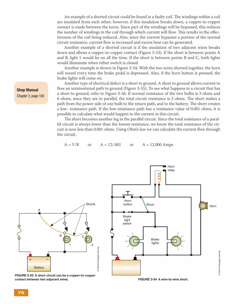
Open
An open is simply a break in the circuit (Figure 3-52). An open is caused by turning a switch off , a break in a wire, a burned-out light bulb, a disconnected wire or connector, or anything that opens the circuit. When a circuit is open, current does not fl ow and the component doesn’t work. Because there is no current fl ow, there are no voltage drops in the circuit. Source voltage is available everywhere in the circuit up to the point at which it is open. Source voltage is even available after a load, if the open is after that point.
Opens caused by a blown fuse will still cause the circuit not to operate, but the cause of the problem is the excessive current that blew the fuse. Nearly all other opens are caused by a break in the continuity of the circuit. Th ese breaks can occur anywhere in the circuit.
Shorts
A short results from an unwanted path for current. Shorted circuits cause an increase in current fl ow by bypassing part of the normal circuit path. Th is increased current fl ow can burn wires or components.
Shop Manual
Chapter 3, page 96
Shop Manual
Chapter 3, page 97
Temperature (°C) Higher
Res
ista
nce
(Ω)
Hig
her
Ordinary metals
PTC thermistor
Conductive state Tripped state PTCresistor
Expanded polymerstructure
Carbon chainsseparated
Many conductivepaths
Dense crystallinestructure
Carbon moleculesin contact
FIGURE 3-51 PTC operation.
© D
elm
ar/C
enga
ge L
earn
ing
+ –
Battery
Open
FIGURE 3-52 An open circuit stops all
current fl ow.
© D
elm
ar/C
enga
ge L
earn
ing
76
An example of a shorted circuit could be found in a faulty coil. Th e windings within a coil are insulated from each other; however, if this insulation breaks down, a copper-to-copper contact is made between the turns. Since part of the windings will be bypassed, this reduces the number of windings in the coil through which current will fl ow. Th is results in the eff ec-tiveness of the coil being reduced. Also, since the current bypasses a portion of the normal circuit resistance, current fl ow is increased and excess heat can be generated.
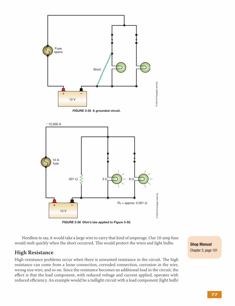
Another example of a shorted circuit is if the insulation of two adjacent wires breaks down and allows a copper-to-copper contact (Figure 3-53). If the short is between points A and B, light 1 would be on all the time. If the short is between points B and C, both lights would illuminate when either switch is closed.
Another example is shown in Figure 3-54. With the two wires shorted together, the horn will sound every time the brake pedal is depressed. Also, if the horn button is pressed, the brake lights will come on.
Another type of electrical defect is a short to ground. A short to ground allows current to fl ow an unintentional path to ground (Figure 3-55). To see what happens in a circuit that has a short to ground, refer to Figure 3-56. If normal resistance of the two bulbs is 3 ohms and 6 ohms, since they are in parallel, the total circuit resistance is 2 ohms. Th e short makes a path from the power side of one bulb to the return path, and to the battery. Th e short creates a low- resistance path. If the low-resistance path has a resistance value of 0.001 ohms, it is possible to calculate what would happen to the current in this circuit.
Th e short becomes another leg in the parallel circuit. Since the total resistance of a paral-lel circuit is always lower than the lowest resistance, we know the total resistance of the cir-cuit is now less than 0.001 ohms. Using Ohm’s law we can calculate the current fl ow through the circuit.
A = V/R or A = 12/.001 or A = 12,000 Amps
Shop Manual
Chapter 3, page 100
+ –
Battery
A
B C
1 2
Shorts
FIGURE 3-53 A short circuit can be a copper-to-copper
contact between two adjacent wires.
© D
elm
ar/C
enga
ge L
earn
ing
Brakelights
Brakelight
switch
Hornrelay
Horn
Hornbutton Short
FIGURE 3-54 A wire-to-wire short.
© D
elm
ar/C
enga
ge L
earn
ing
77
Needless to say, it would take a large wire to carry that kind of amperage. Our 10-amp fuse would melt quickly when the short occurred. Th is would protect the wires and light bulbs.
High Resistance
High-resistance problems occur when there is unwanted resistance in the circuit. Th e high resistance can come from a loose connection, corroded connection, corrosion in the wire, wrong size wire, and so on. Since the resistance becomes an additional load in the circuit, the eff ect is that the load component, with reduced voltage and current applied, operates with reduced effi ciency. An example would be a taillight circuit with a load component (light bulb)
Shop Manual
Chapter 3, page 101
12 V
+ –
Fuseopens
Short
FIGURE 3-55 A grounded circuit.
© D
elm
ar/C
enga
ge L
earn
ing
12 V
+ –
10 Afuse
.001 Ω 3 Ω
RT = approx. 0.001 Ω
˜ 12,000 A
6 Ω
FIGURE 3-56 Ohm’s law applied to Figure 3-55.
© D
elm
ar/C
enga
ge L
earn
ing
78
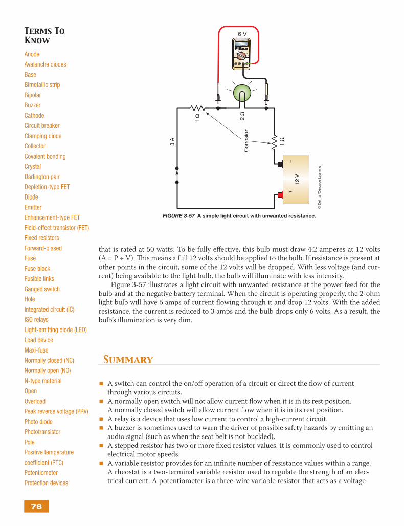
that is rated at 50 watts. To be fully eff ective, this bulb must draw 4.2 amperes at 12 volts (A = P ÷ V). Th is means a full 12 volts should be applied to the bulb. If resistance is present at other points in the circuit, some of the 12 volts will be dropped. With less voltage (and cur-rent) being available to the light bulb, the bulb will illuminate with less intensity.
Figure 3-57 illustrates a light circuit with unwanted resistance at the power feed for the bulb and at the negative battery terminal. When the circuit is operating properly, the 2-ohm light bulb will have 6 amps of current fl owing through it and drop 12 volts. With the added resistance, the current is reduced to 3 amps and the bulb drops only 6 volts. As a result, the bulb’s illumination is very dim.
Summary
A switch can control the on/off operation of a circuit or direct the fl ow of current ■
through various circuits.A normally open switch will not allow current fl ow when it is in its rest position. ■
A normally closed switch will allow current fl ow when it is in its rest position.A relay is a device that uses low current to control a high-current circuit. ■
A buzzer is sometimes used to warn the driver of possible safety hazards by emitting an ■
audio signal (such as when the seat belt is not buckled).A stepped resistor has two or more fi xed resistor values. It is commonly used to control ■
electrical motor speeds.A variable resistor provides for an infi nite number of resistance values within a range. ■
A rheostat is a two-terminal variable resistor used to regulate the strength of an elec-trical current. A potentiometer is a three-wire variable resistor that acts as a voltage
Terms To KnowAnode
Avalanche diodes
Base
Bimetallic strip
Bipolar
Buzzer
Cathode
Circuit breaker
Clamping diode
Collector
Covalent bonding
Crystal
Darlington pair
Depletion-type FET
Diode
Emitter
Enhancement-type FET
Field-effect transistor (FET)
Fixed resistors
Forward-biased
Fuse
Fuse block
Fusible links
Ganged switch
Hole
Integrated circuit (IC)
ISO relays
Light-emitting diode (LED)
Load device
Maxi-fuse
Normally closed (NC)
Normally open (NO)
N-type material
Open
Overload
Peak reverse voltage (PRV)
Photo diode
Phototransistor
Pole
Positive temperature
coeffi cient (PTC)
Potentiometer
Protection devices
12 V
+
–
Cor
rosi
on
1Ω
3 A
2Ω
1Ω
COMA mA A
mV
V
V
mAA
A
V
DIGITAL MULTIMETERRECORD MAX MIN
HZ
%
10 2 3 4 5 6 7 8 9 0
HZ
MAXMIN
6 V
FIGURE 3-57 A simple light circuit with unwanted resistance.
© D
elm
ar/C
enga
ge L
earn
ing
79
divider to produce a continuously variable output signal proportional to a mechanical position.
A diode is an electrical one-way check valve that will allow current to fl ow in one ■
direction only.
Forward bias means that a positive voltage is applied to the P-type material and ■
negative voltage to the N-type material. Reverse bias means that positive voltage is applied tothe N-type material and negative voltage is applied to the P-type material.
A transistor is a three-layer semiconductor that is commonly used as a very fast switching ■
device.
An integrated circuit is a complex circuit of thousands of transistors, diodes, resis- ■
tors, capacitors, and other electronic devices that are formed onto a tiny silicon chip.
Th e protection device is designed to “turn off ” the system it protects. Th is is done by ■
creating an open (like turning off a switch) to prevent a complete circuit.
Fuses are rated by amperage. Never install a larger rated fuse into a circuit than the ■
one that was designed by the manufacturer. Doing so may damage or destroy the circuit.
An open circuit is a circuit in which there is a break in continuity. ■
A shorted circuit is a circuit that allows current to bypass part of the normal path. ■
A short to ground is a condition that allows current to return to ground before it has ■
reached the intended load component.
Relays
Reverse-biased
Rheostat
Short
Short circuits
Solenoid
Sound generator
Stepped resistor
Throw
Thyristor
Transistor
Turn-on voltage
Variable resistors
Wiper
Zener diode
Zener voltage
Terms to Know(continued)
Review Questions
Short-Answer Essays
1. Describe the use of three types of semiconductors.
2. What types of mechanical variable resistors are used on automobiles?
3. Defi ne what is meant by opens, shorts, grounds, and excessive resistance.
4. Explain the eff ects that each type of circuit defect will have on the operation of the electrical system.
5. Explain the purpose of a circuit protection device.
6. Describe the most common types of circuit protec-tion devices.
7. Describe the common types of electrical system (non-electric) components used and how they aff ect the electrical system.
8. Describe the diff erence between a rheostat and a potentiometer.
9. Explain the diff erence between normally open (NO) and normally closed (NC) switches.
10. Explain the diff erences between forward biasing and reverse biasing a diode.
Fill in the Blanks
1. Never install a larger rated into a circuit than the one that was designed by the manufacturer.
2. A can control the on/off operation of a circuit or direct the fl ow of current through various circuits.
3. A normally switch will not allow current fl ow when it is in its rest position. A normally switch will allow current fl ow when it is in its rest position.
4. An is a complex circuit of many transistors, diodes, resistors, capacitors, and other electronic devices that are formed onto a tiny silicon chip.
5. When a voltage is applied to the P-material of a diode and voltage is applied to the N-material, the diode is reverse biased. When a voltage is applied to the N-material of a diode and voltage is applied to the P-material, the diode is forward biased.

80
6. A is used in electronic circuits as a very fast switching device.
7. A is an electrical one-way check valve that will allow current to fl ow in one direction only.
8. A is an electromechanical device that uses low current to control a high-current circuit.
9. A is a three-wire variable resistor that acts as a voltage divider. A is a two-terminal variable resistor used to regulate the strength of an electrical current.
10. Th e requires only a trigger pulse applied to the gate to become conductive.
1. All of the following are true concerning electrical shorts, EXCEPT:A. A short can add a parallel leg to the circuit, which
lowers the entire circuit’s resistance.
B. A short can result in a blown fuse.
C. A short decreases amperage in the circuit.
D. A short bypasses the circuit’s intended path.
2. Which statement is true concerning circuit protection devices?A. A fuse automatically resets after the cause of the
overload is repaired.
B. Circuit protection devices create an open when an overload occurs.
C. An open circuit can cause a blown fuse.
D. Fuses are rated according to the voltage limits.
3. All of the statements concerning circuit components are true, EXCEPT:A. A switch can control the on/off operation of a circuit.
B. A switch can direct the fl ow of current through various circuits.
C. A relay can be an SPDT-type switch.
D. A potentiometer changes voltage drop due to the function of temperature.
4. Which of the following statements is/are correct?A. A zener diode is an excellent component for regu-
lating voltage.
B. A reverse-biased diode lasts longer than a forward-biased diode.
C. Th e switches of a transistor last longer than those of a relay.
D. Both a and c.
5. Th e light-emitting diode (LED):A. Emits light when it is reverse biased.
B. Has a variable turn-on voltage.
C. Has a light color that is defi ned by the materials used to construct the diode.
D. Has a turn-on voltage that is usually less than stan-dard diodes.
6. Which of the following is the correct statement?A. An open means that there is continuity in the
circuit.
B. A short bypasses a portion of the circuit.
C. High amperage draw indicates an open circuit.
D. High resistance in a circuit increases current fl ow.
7. Transistors:A. Can be used to control the switching on/off of
a circuit.
B. Can be used to amplify voltage.
C. Control high current with low current.
D. All of the above.
8. All of the following are true, EXCEPT:A. Voltage drop can cause a lamp in a parallel circuit
to burn brighter than normal.
B. Excessive voltage drop may appear on either the insulated or grounded return side of a circuit.
C. Increased resistance in a circuit decreases current.
D. A diode is used as an electrical one-way check valve.
Multiple Choice
81
9. Which statement is correct concerning diodes?A. Diodes are aligned to allow current fl ow in one
direction only.
B. Diodes can be used to rectify DC voltages into AC voltages.
C. Th e stripe is on the anode side of the diode.
D. Normal turn-on voltage of a standard diode is 1.5 volts.
10. A “blown” fusible link is identifi ed by:A. A burned-through metal wire in the capsule.
B. A bubbling of the insulator material around the link.
C. All of the above.
D. None of the above.