Embed Size (px)
Citation preview

ELECTRICAL AND ELECTRONICS ENGINEERING LABORATORY
1
ELECTRICAL AND ELECTRONICS
ENGINEERING LABORATROY
MANUAL
P MABUHUSSAIN
Assistant Professor
Department of Electrical and Electrical Engineering
D KUMAR
Assistant Professor
Department of Electrical and Electrical Engineering
INSTITUTE OF AERONAUTICAL ENGINEERING
DUNDIGAL – 500 043, HYDERABAD

ELECTRICAL AND ELECTRONICS ENGINEERING LABORATORY
2
INSTITUTE OF AERONAUTICAL ENGINEERING
Dundigal, Hyderabad - 500 043
DEPARTMENT OF ELECTRICAL AND ELECTRONICS
ENGINEERING
ELECTRICAL AND ELECTRONICS ENGINEERING
LABARATORY
LIST OF EXPERIMENTS
S.No EXPERIMENT TITLE Page No
1. VERIFICATION OF KVL AND KCL 3
2. SWINBURNE’S TEST ON DC SHUNT MOTOR 7
3. MAGNETIZATION CHARACTERISTICS OR OPEN CIRCUIT
CHARACTERISTICS OF A DC SHUNT GENERATOR
11
4. BRAKE TEST ON DC SHUNT MOTOR 16
5. OC & SC TESTS ON SINGLE PHASE TRANSFORMER 20
6. BRAKE TEST ON THREE PHASE INDUCTION MOTOR 27
7. REGULATION OF ALTERNATOR USING SYNCHRONOUS
IMPEDANCE METHOD
32
8. SPEED CONTROL OF A D.C.SHUNT MOTOR 38
ELECTRICAL AND ELECTRONICS ENGINEERING LABORATORY
3
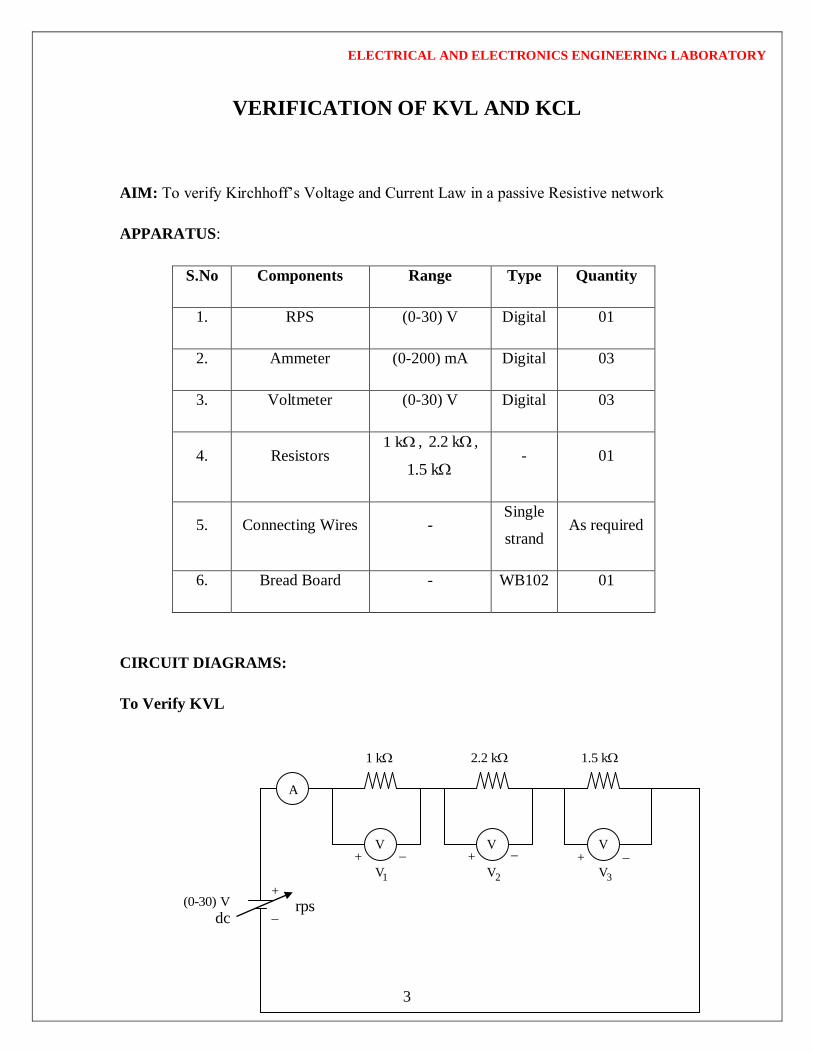
VERIFICATION OF KVL AND KCL
AIM: To verify Kirchhoff’s Voltage and Current Law in a passive Resistive network
APPARATUS:
S.No Components Range Type Quantity
1. RPS (0-30) V Digital 01
2. Ammeter (0-200) mA Digital 03
3. Voltmeter (0-30) V Digital 03
4. Resistors 1 k , 2.2 k ,
1.5 k - 01
5. Connecting Wires - Single
strand As required
6. Bread Board - WB102 01
CIRCUIT DIAGRAMS:
To Verify KVL
VVV
+
1V 2V 3V
rpsdc
(0-30) V
1 k 2.2 k 1.5 k
A
+ + +

ELECTRICAL AND ELECTRONICS ENGINEERING LABORATORY
4
To Verify KCL
PROCEDURE:
1. To verify KVL:
Connect the circuit diagram as shown in figure[1]
Switch ON the supply to RPS.
Apply the voltage (say 5v) and note the voltmeter readings
gradually increase the supply voltage in steps
note the readings of voltmeters
sum up the voltmeter readings(voltage drops) , that should be equal to applied
voltage(e.m.f)
Thus KVL is Verified practically
2. To verify KCL:
Connect the circuit diagram as shown in figure[2]
Switch ON the supply to RPS.
Apply the voltage (say 5v) and note the Ammeter readings
gradually increase the supply voltage in steps
note the readings of Ammeters
sum up the Ammeter readings(I1 and I2) , that should be equal to total current(I)
Thus KCL is Verified practically
2.2 k
(0-30) V
dc
(0-200) mA (0-200) mA1 k
1I
1.5 k
2I
rps
I
A A
A (0-200) mA

ELECTRICAL AND ELECTRONICS ENGINEERING LABORATORY
5
TABULAR COLUMN: 1
S. No.
Applied Voltage
(Volts)
Volt Meter Readings
1V
(Volts)
2V
(Volts)
3V
(Volts)
1 2 3V + V + V
(Volts)
1.
2.
3.
4.
5.
TABULAR COLUMN: 2
S. No. Applied Voltage (V)
Ammeter Readings
I
(Amps)
I1
(Amps)
I2
(Amps)
I1+I2
(Amps)
1.
2.
3.
4.
5.

ELECTRICAL AND ELECTRONICS ENGINEERING LABORATORY
6
PRECAUTIONS:
1. Check for proper connections before switching the supply ON
2. make sure of proper color coding of resistors
3. Avoid parallax errors in measuring instruments.
RESULT:
At 15V supply Theoretical value Practical value
1 2 3V + V + V
I1+I2

ELECTRICAL AND ELECTRONICS ENGINEERING LABORATORY
7
MAGNETIZATION CHARACTERISTIC OF A D.C. SHUNT
GENERATOR
AIM:
To determine experimentally the magnetization or open circuit characteristic of a
D.C Shunt generator and to determine the critical field resistance and critical speed.
APPARATUS:
S.No. Item Type Range Quantity
1 Ammeter (M.C) 0 – 2 A 1 No
2 Voltmeter (M.C) 0 – 300 Volts 1 No
3 Rheostat Wire
wound 370 ohms / 1.7 A 2 No
4 Tachometer Digital 0-3000 rpm 1 No
NAME PLATE DETAILS:
MOTOR GENERATOR
Voltage
Current
Output
Speed
Voltage
Current
Output
Speed

ELECTRICAL AND ELECTRONICS ENGINEERING LABORATORY
8
CIRCUIT DIAGRAM:
PROCEDURE:
1. Choose the proper ranges of meters after noting the name plate details of the
given machine and make the connections as per the circuit diagram.
2. Keep the motor field rheostat (Rfm) in the minimum position. The jockey [J]
of the potential divider should be at the minimum voltage position [P] and start
the MG set.
3. Observe the speed of the generator using a tachometer and adjust to the rated
value by varying the motor field rheostat. Keep the same speed through out the
experiment.
4. Note down the terminal voltage of the generator. This is the e.m.f. due to residual
magnetism.
5. Increase the generator field current If (ammeter) by gradually moving the jockey J
in the direction P to Q. for every value of If, field resistance of the generator note
down the corresponding voltmeter reading. Increase the field current till induced
e.m.f is about 120% of rated value.
6. Repeat the same procedure for decreasing values of the same field currents (Ifg)
and finally note down the emf generated due to residual magnetism.
P
Q J
RFm

ELECTRICAL AND ELECTRONICS ENGINEERING LABORATORY
9
7. Draw the characteristics of generated emf (Efg) versus field current for both
increasing and decreasing values of field current. Draw the average O.C.C
8. Draw a tangent to the initial portion of average O.C.C from the origin. The slope
of this straight line gives the critical field resistance.
TABULAR COLUMN:
S.No.
ASCENDING DESCENDING
Field current
(amp)
Generated voltage
(volts)
Field current
(amp)
Generated voltage
(volts)
PRECAUTIONS:-
1. The experiment should be done at constant speed.
2. The jockey should be moved only in one direction (i.e., from P to Q or Q to P). It
should not be moved back and forth for obtaining a particular field current.
3. At zero field there would be some emf due to residual magnetism
4. Avoid parallax errors and loose connections
MODEL GRAGH:

ELECTRICAL AND ELECTRONICS ENGINEERING LABORATORY
10
VIVA Questions:
1. Under what conditions does the DC shunt generator fail to self-excite?
2. Define critical field resistance?
3. OCC is also known as magnetization characteristic, why?
4. How do you get the maximum voltage to which the generator builds up from
OCC?
5. What does the flat portion of OCC indicate?
6. Why OCC does not start from origin?
7. Does the OCC change with speed?
RESULT:
IfDecreasing
IfIncreasing

ELECTRICAL AND ELECTRONICS ENGINEERING LABORATORY
11
SWINBURNE’S TEST ON A D.C. SHUNT MACHINE
AIM:
To pre-determine the efficiency of a DC shunt machine when run both as generator and
motor.
APPARATUS REQUIRED:
S. No. Name of the Equipment Range Type Quantity
1. Voltmeter M.C 01
M.C 01
2. Ammeter 0-15A M.C 01
3. Rheostat - 01
- 01
4. Tachometer
- DIGITAL 01
Motor
Voltage Output
Current Speed

ELECTRICAL AND ELECTRONICS ENGINEERING LABORATORY
12
CIRCUIT DIAGRAM:
PROCEDURE:
1. Choose the proper ranges of meters after noting the name plate details of the
given machine and make the connections as per the circuit diagram.
2. Keep the motor field rheostat (Rfm) in the minimum position, Start the motor by
closing the switch and operating the starter slowly.
3. Run the motor at rated speed by adjusting the motor field rheostat.
4. Note down the voltage, no load current and field current.
TABULAR COLUMN:
S. No. V ILo If
Model Graph:
20A

ELECTRICAL AND ELECTRONICS ENGINEERING LABORATORY
13
CALCULATIONS FOR SWINBURNE’S TEST
From the no load test results,
Supply voltage = VL Volts.
No load line current = ILoAmperes.
Field current= If Amperes.
Therefore No load Armature Current = Iao = IL-If Amperes.
Resistance cold = Rm
Effective resistance Re = 1.25 x Rm ohms.
No load copper losses are =Iao2 Re
No load power input=VLIL
Constant losses = (No load power input - No load copper losses). ------------ (1)
Efficiency as motor:
Efficiency=output/input = (input – total losses)/ input.
Where total losses = constant losses + variable losses.
Constant losses are known value from the equation (1)
Variable loss = Ia2 Re , where Ia= IL-If
Input = VL IL..VL is rated voltage of the machine
Assume line currents (IL) as 2, 4,6,----20A and find corresponding efficiency
Efficiency as generator:

ELECTRICAL AND ELECTRONICS ENGINEERING LABORATORY
14
Efficiency=output/input = output / (output + total losses).
Where losses = constant losses + variable losses
Constant losses are same for both motor and Generator
Armature Current = Ia = IL + IF
Variable loss = Ia2 Re
Output power = VLIL .VL is rated voltage of the machine
Assume load currents (IL) as 2, 4,6,----20A and find corresponding efficiencies
TABULAR COLUMN:
As a Motor: Rated voltage VL = Rated speed N =
S. No. IL
VLIL
INPUT
Power
Constant
losses
W const.
Copper
losses
Wcu = Ia2 Re
Total losses
=
(Wcons. +
Wcu)
Output power =
(input power –
losses)
As a Generator: Rated voltage VL = Rated speed N =
S. IL VLIL
Out
Constant
losses W const.
Copper losses
Wcu = Ia2 Re
Total loss =
(Wcons. +
Input power =
(output power +

ELECTRICAL AND ELECTRONICS ENGINEERING LABORATORY
15
No. power Wcu) losses)
PRECAUTIONS:
Run the motor at rated speed and rated voltage
Avoid loose connections and parallax errors
RESULTS:
VIVA Questions:
1. Will the values deduced from the Swinburne’s method exactly coincide with the
value realized by direct loading on the machine? Why?
2. Why are the constant losses calculated by this method less than the actual losses?
3. Can we conduct Swinburne’s test on dc series motor?
4. What are the drawbacks of Swinburne’s test?
ELECTRICAL AND ELECTRONICS ENGINEERING LABORATORY
16
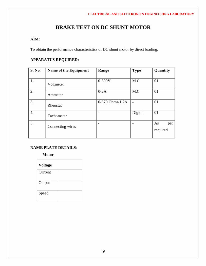
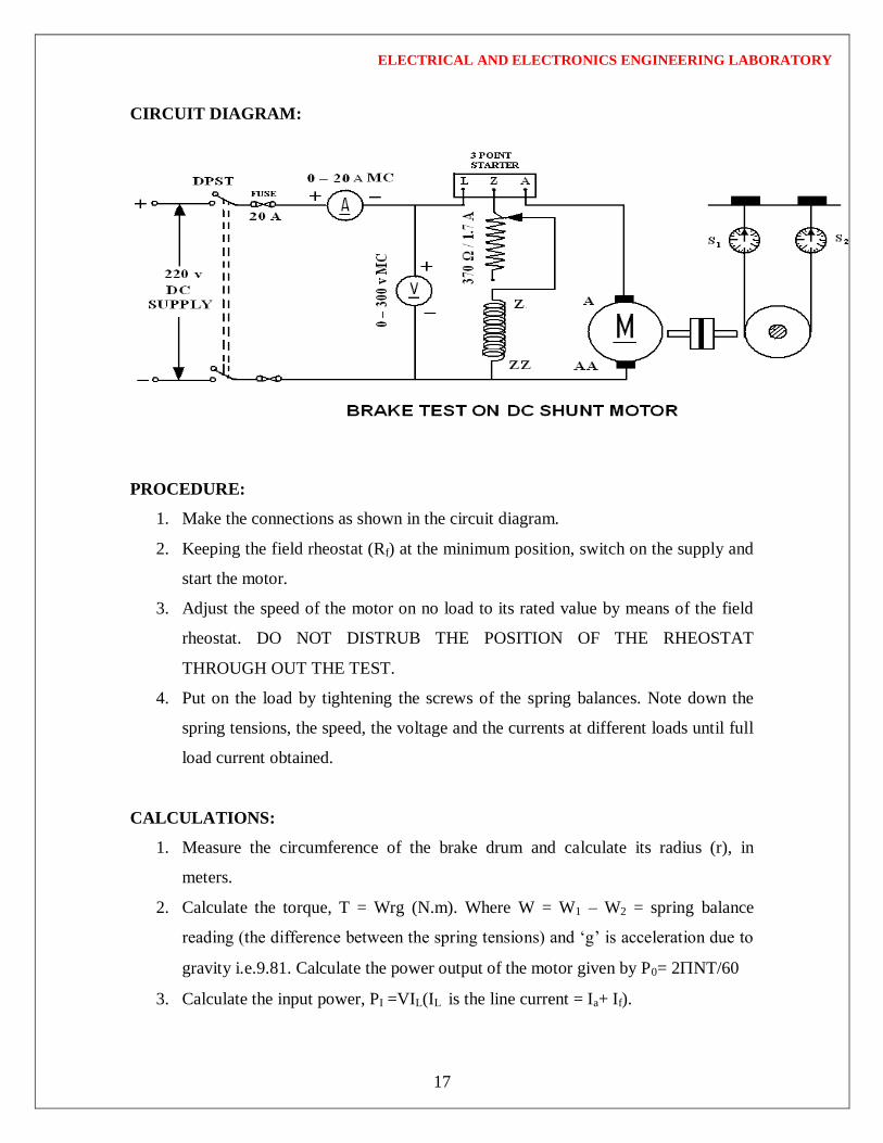
BRAKE TEST ON DC SHUNT MOTOR
AIM:
To obtain the performance characteristics of DC shunt motor by direct loading.
APPARATUS REQUIRED:
S. No. Name of the Equipment Range Type Quantity
1. Voltmeter
0-300V M.C 01
2. Ammeter
0-2A M.C 01
3. Rheostat
0-370 Ohms/1.7A - 01
4. Tachometer
- Digital 01
5. Connecting wires
- - As per
required
NAME PLATE DETAILS:
Motor
Voltage
Current
Output
Speed
ELECTRICAL AND ELECTRONICS ENGINEERING LABORATORY
17
CIRCUIT DIAGRAM:
PROCEDURE:
1. Make the connections as shown in the circuit diagram.
2. Keeping the field rheostat (Rf) at the minimum position, switch on the supply and
start the motor.
3. Adjust the speed of the motor on no load to its rated value by means of the field
rheostat. DO NOT DISTRUB THE POSITION OF THE RHEOSTAT
THROUGH OUT THE TEST.
4. Put on the load by tightening the screws of the spring balances. Note down the
spring tensions, the speed, the voltage and the currents at different loads until full
load current obtained.
CALCULATIONS:
1. Measure the circumference of the brake drum and calculate its radius (r), in
meters.
2. Calculate the torque, T = Wrg (N.m). Where W = W1 – W2 = spring balance
reading (the difference between the spring tensions) and ‘g’ is acceleration due to
gravity i.e.9.81. Calculate the power output of the motor given by P0= 2NT/60
3. Calculate the input power, PI =VIL(IL is the line current = Ia+ If).

ELECTRICAL AND ELECTRONICS ENGINEERING LABORATORY
18
4. Calculate the percentage efficiency, = P0/PIx 100
TABULAR COLUMN
For Load Test:
Radius of Brake Drum:
S.No. VL
(V)
IL
(A)
Speed
(r.p.m.)
Spring Balance
readings
(Kgs)
Torque
(N-m)
I.P
(KW)
O.P
(KW)
0.P / I.P
(%) S1 S2 S1S2
Model graphs:

ELECTRICAL AND ELECTRONICS ENGINEERING LABORATORY
19
RESULT:
VIVA Questions:
1. Why did you use a 3-point starter for starting a D.C shunt motor?
2. If starter is not available, how can you start a D.C motor?
3. What is the efficiency range of a D.C motor?
4. Where can you use the D.C shunt motor?
5. Why is it considered as a constant speed motor?

ELECTRICAL AND ELECTRONICS ENGINEERING LABORATORY
20
OPEN CIRCUIT & SHORT CIRCUIT TEST ON A SINGLE
PHASE TRANSFORMER
AIM:
To perform open circuit and short circuit test on a single phase transformer and to
pre-determine the efficiency, regulation and equivalent circuit of the transformer.
APPARATUS REQUIRED:
Sl.
No. equipment Type Range Quantity
1 Voltmeter MI
(0-300)V
(0-30)V
1 no
1 no
2 Ammeter MI
(0-1)A
(0-10)A
1 no
1 no
3 Wattmeter Dynamo type
(0-300)V LPF
(0-2.5)A
1 no
4 Wattmeter Dynamo type
(0-150)V UPF
(0-10)A
1 no
5 Connecting Wires ***** ***** Required
Transformer Specifications:
Transformer Rating :( in KVA) _________
Winding Details:
LV (in Volts): _______________________
LV side current:_____________________
HV (in Volts): ______________________
HV side Current:___________________

ELECTRICAL AND ELECTRONICS ENGINEERING LABORATORY
21
Type (Shell/Core):___________________
Auto transformer Specifications:
Input Voltage (in Volts):______________
Output Voltage (in Volts): ____________
frequency (in Hz):____________________
Current rating (in Amp):_____________
CIRCUIT DIAGRAM:
OPEN CIRCUIT:
SHORT CIRCUIT:

ELECTRICAL AND ELECTRONICS ENGINEERING LABORATORY
22
PROCEDURE:
Open circuit test:
1. Connections are made as per the circuit diagram.
2. Ensure that variac is set to zero output voltage position before starting the
experiment.
3. Switch ON the supply. Now apply the rated voltage to the Primary winding by
using Variac.
4. The readings of the Voltmeter, ammeter and wattmeter are noted down in Tabular
form.
5. Then Variac is set to zero output position and switch OFF the supply.
6. Calculate Ro and Xo from the readings.
Short Circuit Test:
1. Connections are made as per the circuit diagram.
2. Ensure that variac is set to zero output voltage position before starting the
experiment.
3. Switch ON the supply. Now apply the rated Current to the Primary winding by
using Variac.
4. The readings of the Voltmeter, ammeter and wattmeter are noted down in Tabular
form.
5. Then Variac is set to zero output position and switch OFF the supply.
6. Calculate Ro1 and Xo1 from the readings.
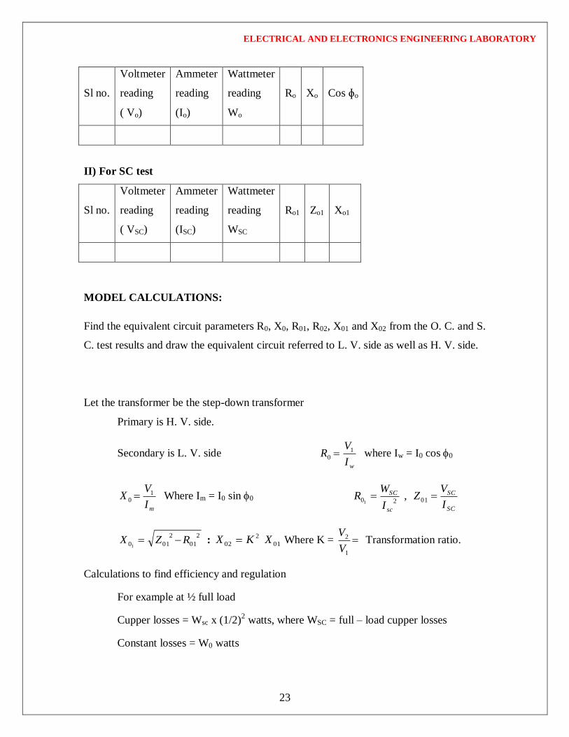
OBSERVATIONS:
1) For OC test
ELECTRICAL AND ELECTRONICS ENGINEERING LABORATORY
23
Sl no.
Voltmeter
reading
( Vo)
Ammeter
reading
(Io)
Wattmeter
reading
Wo
Ro Xo Cos ɸo
II) For SC test
Sl no.
Voltmeter
reading
( VSC)
Ammeter
reading
(ISC)
Wattmeter
reading
WSC
Ro1 Zo1 Xo1
MODEL CALCULATIONS:
Find the equivalent circuit parameters R0, X0, R01, R02, X01 and X02 from the O. C. and S.
C. test results and draw the equivalent circuit referred to L. V. side as well as H. V. side.
Let the transformer be the step-down transformer
Primary is H. V. side.
Secondary is L. V. side wI
VR 1
0 where Iw = I0 cos 0
mI
VX 1
0 Where Im = I0 sin 0
SC
SC
sc
SC
I
VZ
I
WR 0120 ,
1
2
01
2
0101RZX : 01
2
02 XKX Where K = 1
2
V
V Transformation ratio.
Calculations to find efficiency and regulation
For example at ½ full load
Cupper losses = Wsc x (1/2)2 watts, where WSC = full – load cupper losses
Constant losses = W0 watts

ELECTRICAL AND ELECTRONICS ENGINEERING LABORATORY
24
Output = ½ KVA x cos [cos may be assumed]
Input = output + Cu. Loss + constant loss
% 100xInput
Outputefficiency
Efficiency at different loads and P.f’s
cos = ___________
Regulation: From open circuit and Short circuit test
100sincos
Re%2
022022 xV
XIRIgulation
‘+’ for lagging power factors
‘-‘ for leading power factor
S.No p.f. % reg
Lag Lead
Cos = 1.0
S.No Load Wcu (W) O/P (W) I/P (W) (%)

ELECTRICAL AND ELECTRONICS ENGINEERING LABORATORY
25
Cos = 0.8
S.No Load Wcu (W) O/P (W) I/P (W) (%)
GRAPHS: Plots drawn between
(i) % efficiency Vs output

ELECTRICAL AND ELECTRONICS ENGINEERING LABORATORY
26
(ii) % Regulation Vs Power factor
PRECAUTIONS:
(i) Connections must be made tight
(ii) Before making or breaking the circuit, supply must be switched off
RESULT:

ELECTRICAL AND ELECTRONICS ENGINEERING LABORATORY
27
BRAKE TEST ON 3- ɸ SQUIRREL CAGE INDUCTION
MOTOR
AIM:
To determine the efficiency of 3- ɸ induction motor by performing load test. To
obtain the performance curves for the same.
APPARATUS REQUIRED:
Sl.
No. Equipment Type Range Quantity
1 Voltmeter MI (0-600)V 1 no
2 Ammeter MI (0-10)A 1 no
3 Wattmeter Electro dynamo meter type
10A/600V UPF
10A/600V LPF
1 no
1 no
4 Tachometer Digital ***** 1 no
5 Connecting Wires ***** ***** Required
NAME PLATE DETAILS:
Power rating
Voltage
Current
Speed(RPM)

ELECTRICAL AND ELECTRONICS ENGINEERING LABORATORY
28
Frequency
PF
3- ɸ Auto transformer Details:
Input Voltage: __________________ (Volt)
OutputVoltage:__________________(Volt)
Current:_______________________(Amp.)
Freq.:___________________________(Hz)
CIRCUIT DIAGRAM:
PROCEDURE:
1. Connections are made as per the circuit diagram.
2. Ensure that the 3- ɸ variac is kept at minimum output voltage position and belt is
freely suspended.

ELECTRICAL AND ELECTRONICS ENGINEERING LABORATORY
29
3. Switch ON the supply. Increase the variac output voltage gradually until rated
voltage is observed in voltmeter. Note that the induction motor takes large current
initially, so, keep an eye on the ammeter such that the starting current current
should not exceed 7 Amp.
4. By the time speed gains rated value, note down the readings of voltmeter,
ammeter, and wattmeter at no-load.
5. Now the increase the mechanical load by tightening the belt around the brake
drum gradually in steps.
6. Note down the various meters readings at different values of load till the ammeter
shows the rated current.
7. Reduce the load on the motor finally, and switch OFF the supply.
MODEL CALCULATIONS:
Input power drawn by the motor W = (W1 + W2) watts
Shaft Torque, Tsh = 9.81 (S1 ~ S2) R N-m R Radius of drum in mts.
Output power in watts = wattsTN sh
60
2
100% xwattsinpowerInput
wattsinpoweroutputefficiency
p
fxNwherex
N
NNslip s
s
s 120100%
power factor of the induction motor LL IV
W
3cos

ELECTRICAL AND ELECTRONICS ENGINEERING LABORATORY
30
MODEL GRAPHS:
1. Speed or slip Vs output power
2. Torque Vs output power
3. % efficiency Vs output power
OBSERVATIONS:
S.
No.
V
(Volts)
I
(Amps)
Power,
W
(Watts)
Speed
(RPM)
Torque
(N-m)
Spring
balance
(Kg)
% Slip Cos Ø Output
Power
(W)
%η
W1 W2 S1 S2

ELECTRICAL AND ELECTRONICS ENGINEERING LABORATORY
31
VIVA Questions:
1. Why starter is used? What are different types of starters?
2. Compare a slip ring induction motor with cage induction motor?
3. Why the starting torque is zero for a Single Phase induction motor and non-zero
of 3phase induction motor?
4. What are the disadvantages of this method?
5. Can we use rotor resistance method for starting?
PRECAUTIONS:
1. Connections must be made tight
2. Before making or breaking the circuit, supply must be switched off
RESULT

ELECTRICAL AND ELECTRONICS ENGINEERING LABORATORY
32
REGULATION OF ALTERNATOR USING SYNCHRONOUS
IMPEDANCE METHOD
AIM:
To find the regulation of a 3 - ɸ alternator by using synchronous impedance
method.
APPARATUS REQUIRED:
Sl.
No. Equipment Type Range Quantity
1 Voltmeter MI (0-300/600)V 1 no
2 Ammeter MI (0-5/10)A 1 no
3 Ammeter MI (0-2.5/5)A 1 no
3 Rheostat Wire-wound
400 Ω /1.7A
145Ω /2A
1 no
2 no
4 Tachometer Digital ***** 1 no
5 Connecting Wires ***** ***** Required
NAME PLATE DETAILS:
DC Motor(prime mover) 3- ɸ Alternator
KW : Power Rating:
Voltage : PF :
Current : Line voltage:
Speed : Speed
Exctn : Shunt Exctn Voltage:
Voltage : Rated Current :
Field current::

ELECTRICAL AND ELECTRONICS ENGINEERING LABORATORY
33
CIRCUIT DIAGRAM:
PROCEDURE:
Open Circuit Test:
1. Make the connections as per the circuit diagram.
2. Before starting the experiment, the potential divider network in the alternator field
circuit and field regulator rheostat of motor circuit is set minimum resistance
position.
3. Switch ON the supply and close the DPST switch. The DC motor is started by
moving starter handle.
4. Adjust the field rheostat of DC motor to attain rated speed (equal to synchronous
speed of alternator)
5. By decreasing the field resistance of Alternator, the excitation current of
alternator is increased gradually in steps.
6. Note the readings of field current, and its corresponding armature voltage in a
tabular column.
7. The voltage readings are taken upto and 10% beyond the rated voltage of the
machine.

ELECTRICAL AND ELECTRONICS ENGINEERING LABORATORY
34
Short Circuit Test:
1. For Short circuit test, before starting the experiment the potential divider is
brought back to zero output position, i.e., resistance should be zero in value.
2. Now close the TPST switch.
3. The excitation of alternator is gradually increased in steps until rated current
flows in the machine and note down the readings of excitation current and load
current (short circuit current)
4. Switch OFF the supply.
OBSERVATIONS:
Sl
no.
OC test Sl
no.
S.C. test
Field current in
Amp.(I f)
OC voltage
per phase (Vo)
Field current
If( Amp.)
SC current
Isc Amp.
Procedure to find Armature resistance of alternator:
1. Connections are made as per the circuit diagram.
2. Switch ON the supply. By varying the rheostat, take different readings of
ammeter and voltmeter in a tabular column.
3. From the above readings, average resistance Ra of a armature is found out.
ELECTRICAL AND ELECTRONICS ENGINEERING LABORATORY
35
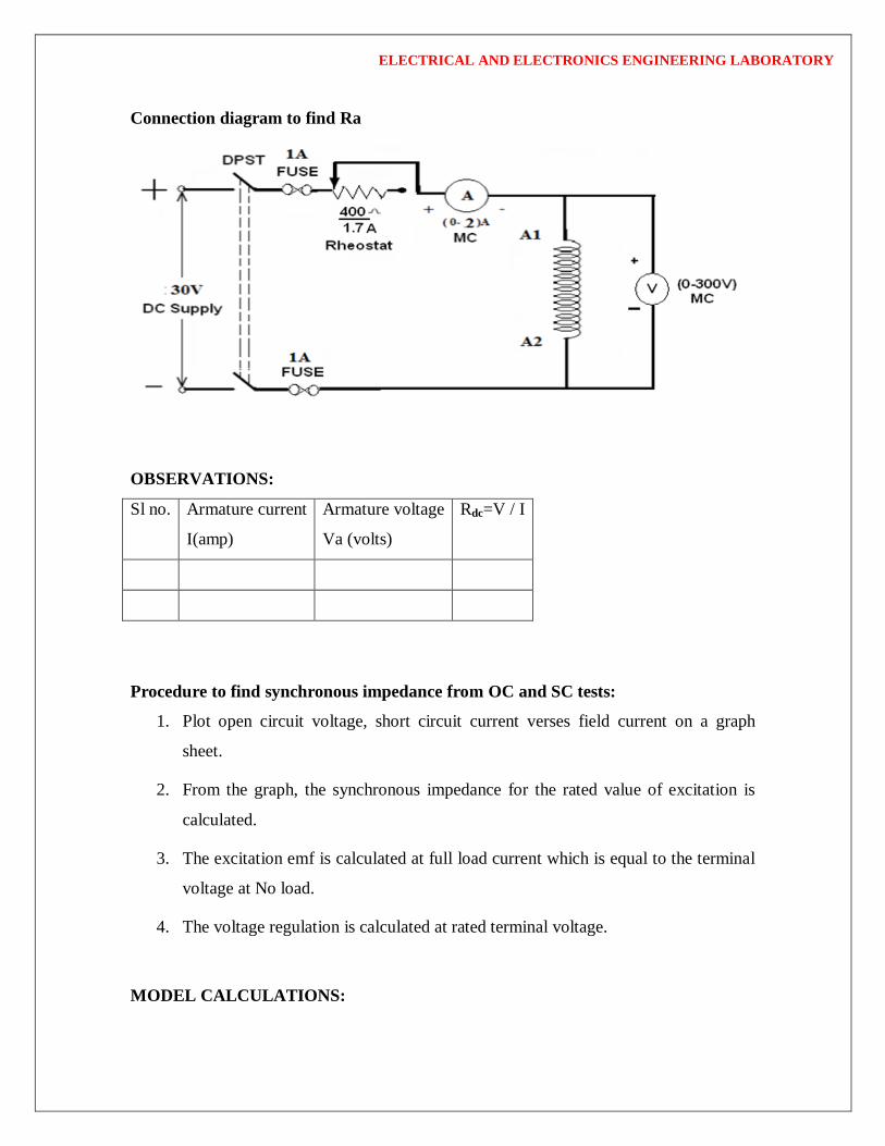
Connection diagram to find Ra
OBSERVATIONS:
Sl no. Armature current
I(amp)
Armature voltage
Va (volts)
Rdc=V / I
Procedure to find synchronous impedance from OC and SC tests:
1. Plot open circuit voltage, short circuit current verses field current on a graph
sheet.
2. From the graph, the synchronous impedance for the rated value of excitation is
calculated.
3. The excitation emf is calculated at full load current which is equal to the terminal
voltage at No load.
4. The voltage regulation is calculated at rated terminal voltage.
MODEL CALCULATIONS:

ELECTRICAL AND ELECTRONICS ENGINEERING LABORATORY
36
SC
OC
SI
VZ for the same If and speed: 22
aSS RZX [Ra RdC]
Generated emf of alternator on no load is
22
0 sincos Saaa XIvRIvE
+ for lagging p.f.
- for leading p.f.
The percentage regulation of alternator for a given p.f. is
100Re% 0 xV
VEg
Where
E0 – generated emf of alternator (or excitation voltage per phase)
V – full load, rated terminal voltage per phase.
MODEL GRAPHS:
Draw the graph between If VS E0 per phase
and If VS ISC

ELECTRICAL AND ELECTRONICS ENGINEERING LABORATORY
37
PRECAUTIONS:
(iii) Connections must be made tight
(iv) Before making or breaking the circuit, supply must be switched off
RESULT:

ELECTRICAL AND ELECTRONICS ENGINEERING LABORATORY
38
SPEED CONTROL OF A D.C.SHUNT MOTOR
AIM:
To vary the speed of the given d. c. shunt motor by armature control & field
control methods and to pre-determine the efficiency of a D.C. Shunt Motor by
Swinburne’s method.
NAME PLATE DETAILS:
Motor
Voltage Output
Current Speed
CIRCUIT DIAGRAMS:
20A

ELECTRICAL AND ELECTRONICS ENGINEERING LABORATORY
39
APPARATUS:
S.No. Item Type Range Quantity
1 Ammeter (M.C)
0 – 2 A
0- 20 A
1 No
1 No
2 Voltmeter (M.C) 0 – 300 Volts 1 No
3 Rheostat Wire wound 370 ohms / 1.7 A 2 No
4 Tachometer Digital 0-3000 rpm 1 No
Procedure of Speed control:
Part-A: Armature control method
1. Choose the proper ranges of meters after noting the name plate details of the given
machine and make the connections as per the circuit diagram.
2. Keep the motor field rheostat (Rfm) in the minimum position and the armature
rheostat (Rfg) in the maximum position, start the MG set.
3. Give supply and accelerate the motor by cutting out the armature circuit resistance
(Ra) until rated voltage is applied to the armature.
4. Adjust the field rheostat (Rf ) to make the motor run at its rated speed(Ns ) when rated
voltage is applied to the armature. This field current corresponds to normal excitation.
5. Keeping normal excitation, vary the armature voltage (Va) by varying the armature
resistance and note down the speed of the motor (N) for different voltages. Note down the
field current also.
6. Tabulate these readings and plot the graph Va Vs N.
ELECTRICAL AND ELECTRONICS ENGINEERING LABORATORY
40
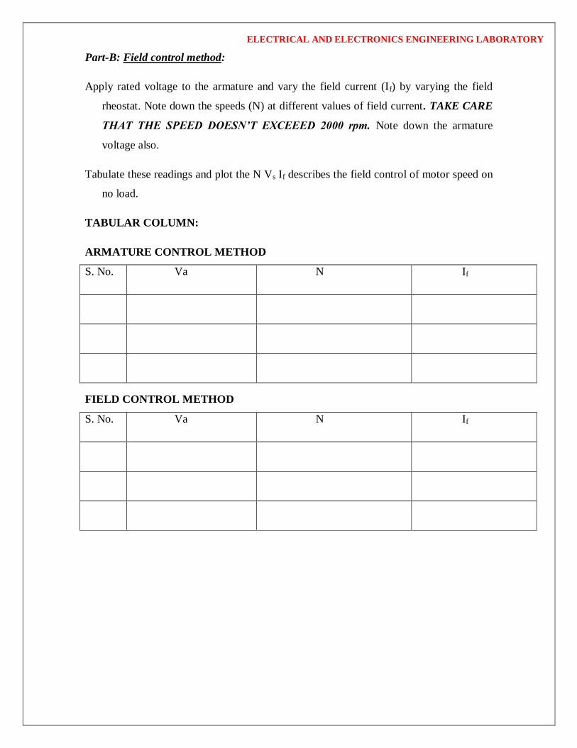
Part-B: Field control method:
Apply rated voltage to the armature and vary the field current (If) by varying the field
rheostat. Note down the speeds (N) at different values of field current. TAKE CARE
THAT THE SPEED DOESN’T EXCEEED 2000 rpm. Note down the armature
voltage also.
Tabulate these readings and plot the N Vs If describes the field control of motor speed on
no load.
TABULAR COLUMN:
ARMATURE CONTROL METHOD
S. No. Va N If
FIELD CONTROL METHOD
S. No. Va N If

ELECTRICAL AND ELECTRONICS ENGINEERING LABORATORY
41
MODEL GRAPH:
Viva Questions:
Speed control:
1 Explain why the graph of armature speed control of motor is linear?
2 What is the shape of the curve of field control of method motor speed? Explain
why is it so?
3 What is the disadvantage of using armature control of speed on load?
4 How do you change the direction of rotation of a D.C. motor?
5 What are the limitations of shunt field control?
6 Comment on the efficiency calculated by this method.
7 Why do you need a starter in a dc motor?
8 What is meant by rated speed?
9 Can we start the dc shunt motor and series motor without load?
10 What is meant by speed regulation?
11 Can we operate a dc motor an ac supply?
12 Can we conduct continuity test on ac supply?
13 What are the other methods of controlling the speed of dc shunt motor?
14 While running if the field winding gets disconnected, what will happen?

ELECTRICAL AND ELECTRONICS ENGINEERING LABORATORY
42
RESULT:-