Embed Size (px)
Citation preview
8/19/2019 Electrical Breaker
http://slidepdf.com/reader/full/electrical-breaker 1/50
8/19/2019 Electrical Breaker
http://slidepdf.com/reader/full/electrical-breaker 2/50
8/19/2019 Electrical Breaker
http://slidepdf.com/reader/full/electrical-breaker 3/50
8/19/2019 Electrical Breaker
http://slidepdf.com/reader/full/electrical-breaker 4/50
8/19/2019 Electrical Breaker
http://slidepdf.com/reader/full/electrical-breaker 5/50

8/19/2019 Electrical Breaker
http://slidepdf.com/reader/full/electrical-breaker 6/50
8/19/2019 Electrical Breaker
http://slidepdf.com/reader/full/electrical-breaker 7/50
8/19/2019 Electrical Breaker
http://slidepdf.com/reader/full/electrical-breaker 8/50
8/19/2019 Electrical Breaker
http://slidepdf.com/reader/full/electrical-breaker 9/50
8/19/2019 Electrical Breaker
http://slidepdf.com/reader/full/electrical-breaker 10/50
8/19/2019 Electrical Breaker
http://slidepdf.com/reader/full/electrical-breaker 11/50
8/19/2019 Electrical Breaker
http://slidepdf.com/reader/full/electrical-breaker 12/50
8/19/2019 Electrical Breaker
http://slidepdf.com/reader/full/electrical-breaker 13/50
8/19/2019 Electrical Breaker
http://slidepdf.com/reader/full/electrical-breaker 14/50
8/19/2019 Electrical Breaker
http://slidepdf.com/reader/full/electrical-breaker 15/50
8/19/2019 Electrical Breaker
http://slidepdf.com/reader/full/electrical-breaker 16/50
8/19/2019 Electrical Breaker
http://slidepdf.com/reader/full/electrical-breaker 17/50
8/19/2019 Electrical Breaker
http://slidepdf.com/reader/full/electrical-breaker 18/50
8/19/2019 Electrical Breaker
http://slidepdf.com/reader/full/electrical-breaker 19/50
8/19/2019 Electrical Breaker
http://slidepdf.com/reader/full/electrical-breaker 20/50
8/19/2019 Electrical Breaker
http://slidepdf.com/reader/full/electrical-breaker 21/50
8/19/2019 Electrical Breaker
http://slidepdf.com/reader/full/electrical-breaker 22/50
8/19/2019 Electrical Breaker
http://slidepdf.com/reader/full/electrical-breaker 23/50
8/19/2019 Electrical Breaker
http://slidepdf.com/reader/full/electrical-breaker 24/50
8/19/2019 Electrical Breaker
http://slidepdf.com/reader/full/electrical-breaker 25/50
8/19/2019 Electrical Breaker
http://slidepdf.com/reader/full/electrical-breaker 26/50
8/19/2019 Electrical Breaker
http://slidepdf.com/reader/full/electrical-breaker 27/50
8/19/2019 Electrical Breaker
http://slidepdf.com/reader/full/electrical-breaker 28/50
8/19/2019 Electrical Breaker
http://slidepdf.com/reader/full/electrical-breaker 29/50
8/19/2019 Electrical Breaker
http://slidepdf.com/reader/full/electrical-breaker 30/50
8/19/2019 Electrical Breaker
http://slidepdf.com/reader/full/electrical-breaker 31/50
8/19/2019 Electrical Breaker
http://slidepdf.com/reader/full/electrical-breaker 32/50
8/19/2019 Electrical Breaker
http://slidepdf.com/reader/full/electrical-breaker 33/50
8/19/2019 Electrical Breaker
http://slidepdf.com/reader/full/electrical-breaker 34/50
8/19/2019 Electrical Breaker
http://slidepdf.com/reader/full/electrical-breaker 35/50
8/19/2019 Electrical Breaker
http://slidepdf.com/reader/full/electrical-breaker 36/50
8/19/2019 Electrical Breaker
http://slidepdf.com/reader/full/electrical-breaker 37/50
Medium Voltage Circuit Breaker Course Chapter 2.0
Student Manual Circuit Breaker Mechanical Components and Operation
USNRC 2-1 Rev 0
2.0 CIRCUIT BREAKER COMPONENTS and OPERATION
Learning Objectives
This chapter will provide a general overview of the mechanical components of acircuit breaker. A brief description of the components and their function will beprovided along with a contrast between manufactures where applicable.
As a result of this lesson you will be able to:
1. Describe different breaker closing methods
2. Be able to recognize and describe the function of breaker mechanical
components3. Know the difference between the line and load side primary conductors
4. Understand how the breakers are inserted into the switchboard
5. Understand the difference between Primary and Secondary current carryingcomponents
6. Understand the difference between main and arcing contacts
7. Understand the function of a puffer
8. Understand the operating sequence of an operating mechanism
2.1 CIRCUIT BREAKER OPERATION
Medium voltage breakers are designed to be operated electrically by a closingsolenoid or a stored energy mechanism. Manual operation is used primarily forbreaker maintenance.
2.1.1 Manual operation
Only low voltage circuit breakers (600V and under) are designed with manualoperation as their primary method of closing and tripping.
2.1.1.1 Manual breakers are closed by operating a handle on the front ofthe breaker, which will prime a closing spring, which closes thebreaker contacts or may move the contacts to a closed position viaan operating linkage.
8/19/2019 Electrical Breaker
http://slidepdf.com/reader/full/electrical-breaker 38/50
Medium Voltage Circuit Breaker Course Chapter 2.0
Student Manual Circuit Breaker Mechanical Components and Operation
USNRC 2-2 Rev 0
2.1.1.2 Medium voltage breaker manual operation
Manual operation is primarily for maintenance and is performedby compressing the closing spring with a manual closing springcharging device, closing and tripping mechanisms are normallydual operating and manual closing and tripping operation isperformed from the breaker front plate.
2.1.2 Electrical operation
2.1.2.1 Solenoid operated:
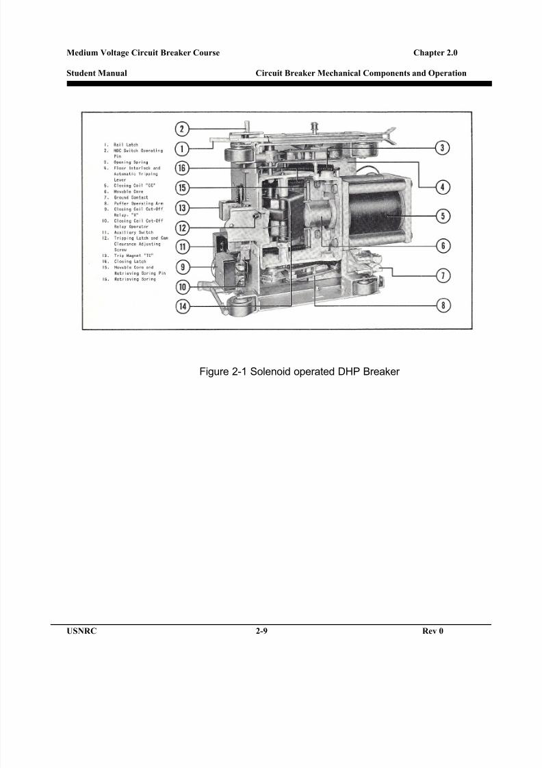
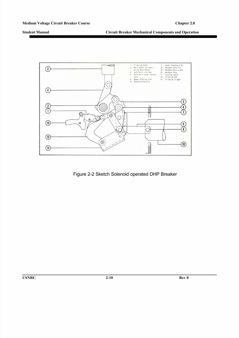
The first electrically operated breakers were closed by asolenoid close coil. The coil pulled a solenoid slug, whichactuated the closing mechanism. Figures 2-1 and 2-2 show thefirst generation Westinghouse DHP circuit breaker with asolenoid-closing coil. Solenoid closing operation was replacedby stored energy breakers.
2.1.2.2 Stored energy closing:
Stored energy design breakers utilize a charging motor tocharge a closing spring to a primed position ready to close. Aclosing coil or manual close button unlatches the closing springholding latch, which discharges the spring closing the breakercontacts.
2.2 MAIN CURRENT CARRYING COMPONENTS
The complete current carrying assembly is called a phase or pole. Medium
voltage breakers are primarily used in Alternating Current (AC) applications, butthere are some Direct Current (DC) applications.
Alternating current (AC) breakers have three phases and are normallydesignated as A, B, and C phase, looking at the front of the breaker and goingleft to right.
8/19/2019 Electrical Breaker
http://slidepdf.com/reader/full/electrical-breaker 39/50
Medium Voltage Circuit Breaker Course Chapter 2.0
Student Manual Circuit Breaker Mechanical Components and Operation
USNRC 2-3 Rev 0
Direct Current (DC) breakers are usually used in low voltage applications andnormally are two Pole design. There are also applications in the mining and rail
industries, which use single-pole DC breakers.
The phase or pole design in all breakers is essentially the same and will consist ofsome or all of the following components.
1) Primary disconnects.2) Primary conductors (Bushing)3) Moving contact arm4) Contacts5) Puffer device
2.2.1 Primary Disconnects
The circuit breaker “plugs into” the switchboard compartment using a primarydisconnect (Main Current Carrying) and secondary disconnect (ControlPower).
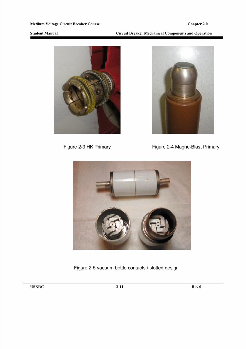
The primary disconnects connect the breaker phase to the switchboard sidebus. The primary disconnects are a set of silver plated copper fingers heldtogether with springs and are permanently mounted to the breaker bushings(Figure 2-3). On some breaker designs such as a GE Magne-Blast (Figure 2-4) the bushing is a silver plated copper stud and the primary disconnects arepermanently attached to the to switchboard side conductor.
The disconnect is designed to float, which means they are not rigidlymounted, and allows for any minor misalignment of the breaker to cubicle.The opening on the disconnect is wider on the outside and tapers smaller atthe point where the breaker is fully racked into the connected position.
The primary disconnect does not exert full spring tension on the bus when outof the cubicle, only when inserted into the cubicle. The switchboard sideconductor expands the fingers and causes the springs to exert pressure onboth the breaker and cubicle pole.
As the breaker is racked into the cubicle the primary will be in line with theswitchboard side conductor and self aligns as the breaker is moving to theconnect position. The fingers of the primary disconnects are also coated witha lubrication to allow for a smooth insertion and also to protect the silver-plating from friction wear.
8/19/2019 Electrical Breaker
http://slidepdf.com/reader/full/electrical-breaker 40/50
Medium Voltage Circuit Breaker Course Chapter 2.0
Student Manual Circuit Breaker Mechanical Components and Operation
USNRC 2-4 Rev 0
2.2.2 Primary Conductor
The primary conductor, also referred to as a bushing, is a solid copperbus with silver-plating on both ends. Some manufactures also braise athin silver coating at the moving contact pivot or connection surface forbetter conductivity. Each conductor is covered with or encased in aninsulating material to isolate it from the breaker frame.
Each phase will have a “Line” side and a “Load” side bushing. The loadSide bushing is normally attached to the moving contact arm and the lineside is normally the stationary contact. An exception to this is a Bus TieBreaker, which can feed from both bushings depending on which side ofthe switchboard it, is feeding.
2.2.3 Moving Contact Arm
The moving contact arm is silver plated copper and connects to theprimary bushing at a pivot point on the load side primary conductor. Thearms are held by a bolt and nut assembly, which exerts a set tension on aspring or springs to provide pressure for a good electrical connection.
The moving contacts are attached to one end of the contact arm and theother end is connected to an insulated push link that connects the moving
arm to the operating mechanism.
2.2.4 Contacts
• Air Circuit Breakers (ACB): The contact assembly of most mediumvoltage ACB’s consists of two contact types: main contacts and arcingcontacts.o Arcing Contacts: During the close operation of the breaker, the arc
contact touches first and when tripped (opened) break last. Thearcing contacts are designed to be strong enough to withstand the
heat of the arc, and are normally a silver tungsten alloy. Arccontacts are considered sacrificial and it is not unusual to haveminor burning and arcing damage. The silver provides somecurrent carrying characteristics, but the tungsten is not a goodconductor. Therefore, arc contacts cannot carry the normal breakerloads.
8/19/2019 Electrical Breaker
http://slidepdf.com/reader/full/electrical-breaker 41/50
Medium Voltage Circuit Breaker Course Chapter 2.0
Student Manual Circuit Breaker Mechanical Components and Operation
USNRC 2-5 Rev 0
o Main Contacts: The main contacts carry the breaker load. Air circuitbreaker main contacts are normally a silver plated copper body with a
silver cadmium oxide contact material attached at the connection pointof the moving and the stationary contacts.
Pure silver or silver plated copper could not withstand the force ofopening and closing the breaker, and therefore the contact tip is asilver alloy; silver cadmium oxide is commonly used for this applicationbecause it is a good conductor and adds enough strength to minimizethe wear from the opening and closing impact.
The contact surfaces of the arcing and main contacts are not silver-plated. The plating deposited during the plating process is removed, as
it would burn off during arcing.
• Vacuum Breakers: There are only main contacts within a vacuum bottle.The commonly used materials for vacuum breakers are either copper-bismuth or copper-chrome alloys. The shape is also important and twobasic shapes are used cupped axial magnetic design and a slotteddesign. Figure 2-5 shows the slotted design.
• SF6 Gas Breakers: Have a main and arcing contact design similar to ACB’s.
2.2.5 Puffer Device
A puffer device is used in most medium voltage air breakers to helpaccelerate the arc into the arc chute. The puffer will have a tube positionedunder the stationary contacts and uses the movement of the mechanism orcontact arm to displace air from a chamber on the breaker into the arc path.
2.3 CLOSING SHAFT AND CONNECTING LINKS
The closing shaft is the device that connects the operating mechanism to theinsulated links that operate the moving contacts. The closing shaft has differentnames depending on the breaker manufacturer:
• General Electric refers to it as “crank shaft “and “Jack shaft”,
• Westinghouse/Cutler Hammer a “Pole Operating Shaft”, (See Figure 1-2, Item 2)

8/19/2019 Electrical Breaker
http://slidepdf.com/reader/full/electrical-breaker 42/50
Medium Voltage Circuit Breaker Course Chapter 2.0
Student Manual Circuit Breaker Mechanical Components and Operation
USNRC 2-6 Rev 0
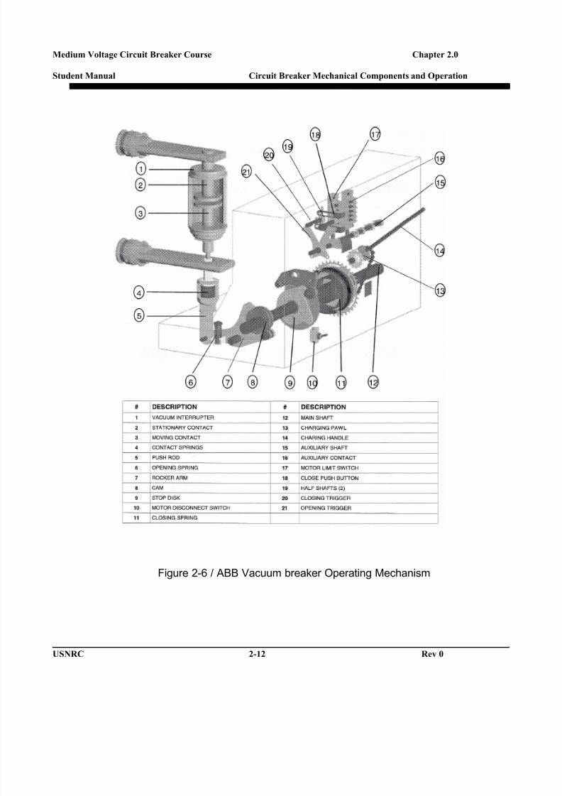
• ABB calls it a “Jack shaft” and the on the new vacuum breakers it is called a“Main Shaft”. (See Figure 2- 6, Item 12)
The closing shaft has three-connection pivot points where the phase insulatedlinks are connected. The operating mechanism driving link is also connected tothe operating shaft under the center phase.
2.4 OPERATING MECHANISM
All stored energy breakers operate on the same principle. Before discussing theoperating mechanism the following are common terms used for mechanismcomponents:
• Closing arms/lever or closing cranks: The arms attached to the closing shaft.
• Trip Latch: The latch, which rests on the trip latch roller when the breaker isclosed. Trips the breaker when closed.
• Trip Latch Roller: Roller that rests on the trip latch.
• Closing Roller: The roller on the mechanism linkage. The closing roller rideson the closing cam during the close operation.
• Closing Cam: The closing cam is a drop cam shape design and pushes the
breaker linkage to the close position.
• Prop Latch (DHP = Tripping cam): Latch used to hold the mechanism in theclosed position after closing to allow the mechanism to recharge.
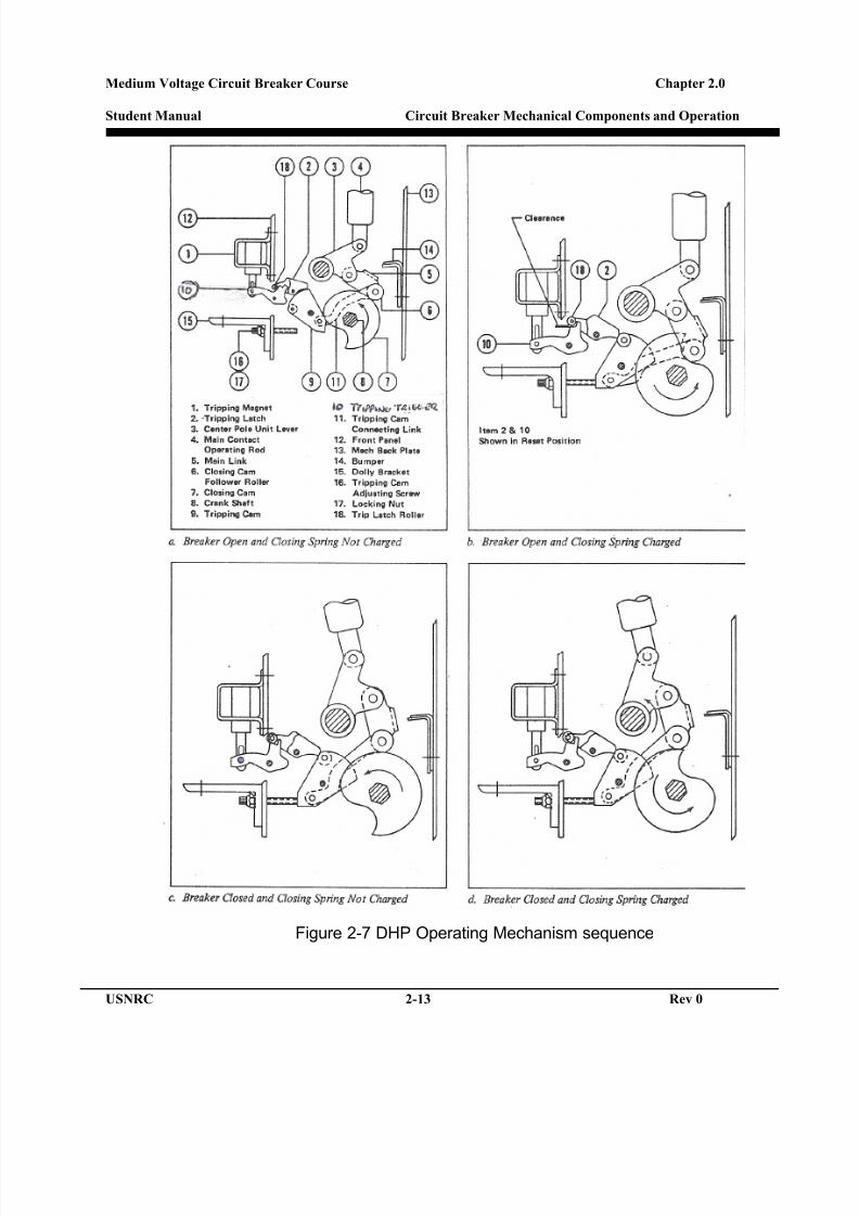
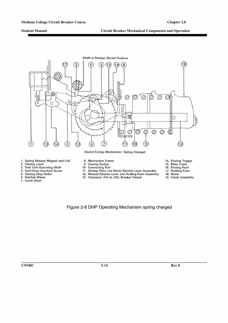
2.4.1 Breaker operating sequence:
See Figure 2-7 and 2-8 for mechanism position.
• A charging motor or manual charge handle operates the chargingcrank and pushes a ratchet wheel to compress the closing spring.When the breaker reaches the charged position and the closing latchis holding the closing spring in a fully compressed position (Figure 2-8Item 2 and 5).
8/19/2019 Electrical Breaker
http://slidepdf.com/reader/full/electrical-breaker 43/50
Medium Voltage Circuit Breaker Course Chapter 2.0
Student Manual Circuit Breaker Mechanical Components and Operation
USNRC 2-7 Rev 0
• The trip latch will now be in a position to hold the mechanism in a closedposition when the close operation is initiated. (Figure 2-6b Item 10 and 18)
• When the close latch is moved the closing spring will drive a closing camand engages the closing mechanism linkage, the mechanism linkage isattached to the operating shaft, which in turn is attached to the movingcontacts, and the breaker will close. (Figure 2-7c)
• For the breaker to remain in the closed position the linkage has to be heldin a closed position by the trip latch.
• To allow the breaker to recharge and remain closed the breaker will use aprop latch (DHP = Tripping Cam) in conjunction with the trip latch to hold
the mechanism in a closed position. This will allow the mechanism torecharge. (Figure 2-8d)
• To trip the breaker the trip latch is moved allowing the mechanism togglesto collapse.
2.5 BREAKER SPRINGS
2.5.1 Closing Spring
The closing spring provide the energy to close the contacts and is the largestspring on any stored energy breaker. It is sized according to the continuousamperage and interrupting amperage of the breaker. There can be one ortwo closing springs depending on the type and size of the breaker.
2.5.2 Opening springs
The opening spring or springs open the breaker during a trip operation. Thequantity and size of the opening springs will depend on the interruptingrequirements of the circuit breaker. Opening springs are normally located onthe outside phases and are attached to the closing shaft.
The springs are compressed or stretched during the close operation andremain stretched until a close signal is given to the breaker. Most breakershave two large springs but some breakers will have more.

8/19/2019 Electrical Breaker
http://slidepdf.com/reader/full/electrical-breaker 44/50
Medium Voltage Circuit Breaker Course Chapter 2.0
Student Manual Circuit Breaker Mechanical Components and Operation
USNRC 2-8 Rev 0
2.5.3 Contact Springs
The contact springs (Arcing and Main) provide the pressure required to give atight connection between the moving and stationary contacts. The maincontact springs are normally located on the stationary main contacts and arecompressed when the contacts are closed. The arcing contact springs canbe on the stationary or moving contacts and also are compressed when thecontacts are closed.
2.5.4 Mechanism Springs
The operating mechanism has several springs associated with latch actuationand resetting operations. Significant springs normally found in all
mechanisms are:
• Trip Latch Spring: Resets and holds trip latch in position.
• Close Latch Spring: Resets and holds close latch in position.
• Prop Latch Spring: Pulls the prop on to latch.
2.6 RACKING MECHANISM
A racking mechanism or levering system is used to insert and remove the circuitbreaker from the circuit breaker compartment.
Most breakers use a mechanism mounted on the breaker and rack the breaker intoposition horizontally. The GE Magna-Blast Model AM is the only breaker that hasits racking mechanism in the switchboard cubicle and racks the breaker intoposition vertically.
8/19/2019 Electrical Breaker
http://slidepdf.com/reader/full/electrical-breaker 45/50
Medium Voltage Circuit Breaker Course Chapter 2.0
Student Manual Circuit Breaker Mechanical Components and Operation
USNRC 2-9 Rev 0
Figure 2-1 Solenoid operated DHP Breaker
8/19/2019 Electrical Breaker
http://slidepdf.com/reader/full/electrical-breaker 46/50
Medium Voltage Circuit Breaker Course Chapter 2.0
Student Manual Circuit Breaker Mechanical Components and Operation
USNRC 2-10 Rev 0
Figure 2-2 Sketch Solenoid operated DHP Breaker
8/19/2019 Electrical Breaker
http://slidepdf.com/reader/full/electrical-breaker 47/50
Medium Voltage Circuit Breaker Course Chapter 2.0
Student Manual Circuit Breaker Mechanical Components and Operation
USNRC 2-11 Rev 0
Figure 2-3 HK Primary Figure 2-4 Magne-Blast Primary
Figure 2-5 vacuum bottle contacts / slotted design
8/19/2019 Electrical Breaker
http://slidepdf.com/reader/full/electrical-breaker 48/50
Medium Voltage Circuit Breaker Course Chapter 2.0
Student Manual Circuit Breaker Mechanical Components and Operation
USNRC 2-12 Rev 0
Figure 2-6 / ABB Vacuum breaker Operating Mechanism
8/19/2019 Electrical Breaker
http://slidepdf.com/reader/full/electrical-breaker 49/50
Medium Voltage Circuit Breaker Course Chapter 2.0
Student Manual Circuit Breaker Mechanical Components and Operation
USNRC 2-13 Rev 0
Figure 2-7 DHP Operating Mechanism sequence
8/19/2019 Electrical Breaker
http://slidepdf.com/reader/full/electrical-breaker 50/50
Medium Voltage Circuit Breaker Course Chapter 2.0
Student Manual Circuit Breaker Mechanical Components and Operation
Figure 2-8 DHP Operating Mechanism spring charged