Embed Size (px)
Citation preview
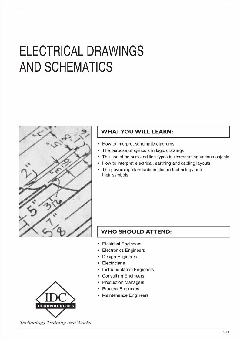
• How to interpret schematic diagrams
• The purpose of symbols in logic drawings
• The use of colours and line types in representing various objects
• How to interpret electrical, earthing and cabling layouts
• The governing standards in electro-technology andtheir symbols
• Electrical Engineers
• Electronics Engineers
• Design Engineers
• Electricians
• Instrumentation Engineers
• Consulting Engineers
• Production Managers
• Process Engineers
• Maintenance Engineers
ELECTRICAL DRAWINGS
AND SCHEMATICS
WHAT YOU WILL LEARN:
WHO SHOULD ATTEND:
2.63
DAY TWO
LOGIC DIAGRAMS
• Purpose
• Typical examples
• Use of symbols
• Applications
• Logic diagrams spread over a number ofsheets
• Cross-referencing
Practical exercises involving reading and interpretation of logic diagrams
CABLING AND WIRING DRAWINGS
• Purpose
• Typical examples
• Sub types of cabling drawings
• Applications
• Conventions used
Practical exercises involving reading and interpretation of cabling drawings
LAYOUT DRAWINGS
• Purpose
• Typical examples
• Sub types of layout drawings
• Applications
• Conventions used
Practical exercises involving reading and interpretation of layout drawings
ADVANCES ARISING FROMCOMPUTER AIDED DRAFTING (CAD)
• Drawing office revolution by CAD and therole of PC based CAD applications
• 2-D and 3-D CAD applications and linksto CAM
• Drawing to true dimensions in CADapplications
• Use of symbols, attributes and symbollibraries
• Automated bill of material generationfrom a CAD drawing
• Information sharing on multi-disciplinarydrawings
• Concept of layers and their use in sharinginformation
• Automation of drawing throughprogramming
• Linking imagery with drawings - GISrelated applications
MANAGEMENT OF DRAWINGS
• Planning and assigning of drawings
• Need for drawing numbering standards
• Drawing process flow
• Revision control and ownership ofdrawing
• Comments and their marking
• Drawing management system for workflow control
• On-line distribution of drawings - the endof the era of paper drawings?
• Drawing as a database for engineeringand construction - the future
SUMMARY AND OPEN FORUM
DAY ONE
INTRODUCTION
• Drawings - their relevance to engineering
• Origin of worldwide standards inelectro-technology
• Purposes served by different types ofdrawings
• Standards in a drawing office
• Organisation of a typical drawing office
• Printing and distribution - different optionsfor making multiple copies
COMPONENTS OF A DRAWING,DRAWING SIZES AND SCALES
• What is a typical engineering drawingmade up of?
• Various categories of electrical drawings
• Planning a drawing
• Title block in a drawing and what shoulda title block contain?
• Legend block
• Bill of materials block
• Drawing notes block
• Revision history, revision numbering anduse of revision marks
SYMBOLS USED IN ELECTROTECHNOLOGY AND GOVERNINGSTANDARDS
• Which are the drawings that needsymbols?
• Symbols as per electro-technologystandards - particularly IEC
• Non-standard symbols - when and why?
• Use of colors and line types inrepresenting various services
• Company standards for drawings - why?
SINGLE LINE AND THREE LINEDIAGRAMS
• Purpose
• Typical examples
• Use of symbols
• The differences between single line andthree line diagrams
• Applications
• Conventions used
Practical exercises involving reading and interpretation of single line diagrams
SCHEMATIC DIAGRAMS
• Purpose
• Typical examples
• Use of symbols
• Applications
• Schematics spread over a number ofsheets
• Cross-referencing between coils andcontacts
Practical exercises involving reading and interpretation of schematic drawings
The Program
The objective of this workshop is to familiarise
engineers and technicians with the various
standards and practices used for reading and
interpreting electrical drawings and schematics.
It will help you understand the symbols and the
language used in electrical drawings in line with
the international standards and practices, giving
you a detailed insight into the various types of
electrical drawings used in the industry, their
purpose and applications and also to differentiate
between the types of drawings.
The workshop observes the practices being
followed by drawing offices for the development,
management and control of drawings.
This workshop will be helpful for those from the
electrical discipline - in the field of design,
project or maintenance.
The Workshop
Practical Sessions
This is a practical, hands on workshop enabling
you to work through practical exercises which
reinforce the concepts discussed.
To gain full value from this workshop, please
bring your laptop/notebook computer.
[email protected] • www.idc-online.com
✔ SAVE over 50% byhaving an IDC workshoppresented at yourpremises.
✔ Customise the trainingto YOUR workplace.
✔ Have the trainingdelivered when andwhere you need it.
Contact us for aFREE proposal.
On-Site Training