Embed Size (px)
Citation preview

51
Chapter 16
Electrical Energy and Capacitance
Problem Solutions
16.1 (a) Because the electron has a negative charge, it experiences a force in the d irection
opposite to the field and, when released from rest, will move in the negative x-
d irection. The work done on the electron by the field is
19 2 181.60 10 C 375 N C 3.20 10 m 1.92 10 Jx xW F x qE x
(b) The change in the electric potential energy is the negative of the work done on the
particle by the field . Thus,
181.92 10 JPE W
(c) Since the Coulomb force is a conservative force, conservation of energy gives
0KE PE , or conservation of linear momentum. , and
18
6
31
2 1.92 10 J22.05 10 m s in the -direction
9.11 10 kgf
e
PEv x
m
16.2 (a) The change in the electric potential energy is the negative of the work done on the
particle by the field . Thus,
6 2 40 5.40 10 C 327 N C 32.0 10 m 5.65 10 J
x yPE W qE x qE y
q x
(b) The change in the electrical potential is the change in electric potential energy per
unit charge, or
4
-6
5.65 10 J105 V
+5.40 10 C
PEV
q

Electrical Energy and Capacitance 52
16.3 The work done by the agent moving the charge out of the cell is
input field
19 3 20J1.60 10 C 90 10 1.4 10 J
C
eW W PE q V
16.4 p
p
mv v
m, so
17191.92 10 J
3.20 10 C+60.0 J C
e
f i
PEq
V V
16.5 6
2
25 000 J C1.7 10 N C
1.5 10 m
VE
d
16.6 Since potential d ifference is work per unit charge W
Vq
, the work done is
27
7 6
27
1.67 10 kg1.05 10 m s 2.64 10 m s
6.64 10 kg
p
p
mv v
m
16.7 (a) ek QV
r
(b) 19 5 141.60 10 C 1.13 10 N C 1.80 10 NF q E
(c)
14 3 17
cos
1.80 10 N 5.33 2.90 10 m cos0 4.38 10 J
W F s
16.8 (a) Using conservation of energy, 0KE PE , with 0fKE since the particle is
“ stopped” , we have
0s
The required stopping potential is then
16
3
19
3.70 10 J2.31 10 V 2.31 kV
1.60 10 C
PEV
q

Electrical Energy and Capacitance 53
(b) Being more massive than electrons, protons traveling at the same initial speed will
have more initial kinetic energy and require a greater magnitude stopping potential.
(c) Since cos 0 , the ratio of the stopping potential for a proton to that for an electron
having the same initial speed is
cos 0
16.9 (a) Use conservation of energy
s e s ef i
KE PE PE KE PE PE
or 0s eKE PE PE
2 2
2 79 22 eef
i i
k e ek Qqr
m v m v since the block is at rest at both beginning and end.
22
9 19
2
14
227 7
N m2 8.99 10 158 1.60 10 C
C2.74 10 m
6.64 10 kg 2.00 10 m sfr , where
2 2 2
2 2 2 2
diagonal a a a ar is the maximum stretch of the spring.
total singlecharge
4 4 4 4 22
e ee
k Q k Q QV V k
r aa
Thus, 2
max max
10 0
2kx QE x , giving
6 4
2
max
2 35.0 10 C 4.86 10 V m24.36 10 m 4.36 cm
78.0 N m
QEx
k
(b) At equilibrium, max maxmax
8 61.11 10 F 3.0 10 N C 800 m 27 C
Q C V C E d
Therefore, 27.0 C
3.00 F9.00 V
QC
V
The amplitude is the d istance from the equilibrium position to each of the turning
points at 0 and 4.36 cmx x , so max2.18 cm 2A x

Electrical Energy and Capacitance 54
(c) From conservation of energy, eq 1 2 25.0 F+40.0 F 65.0 FC C C . Since
3 3
40 25 2.00 10 C 1.25 10 C 750 CQ Q Q , this gives
22
max2
2 2
k AkxV
Q Q or
6 64.00 10 F 1.50 V 6.00 10 C 6.00 CQ C V
16.10 Using 2
0
1
2y yy v t a t for the full flight gives
2
0
10
2y yv t a t , or 2 2 2 2 10.0 F 20.0 FpC C C
Then, using
1 1
eq
1 2
1 1 1 16.04 F
8.66 F 20.0 Fp p
CC C
for the upward part
of the flight gives
2 2
0 0 0
max
0
0 20.1 m s 4.10 s20.6 m
2 4 42 2
y y y
y y
v v v ty
a v t
From Newton’ s second law, y
y
F mg qE qEa g
m m m. Equating
this to the earlier result gives 1 , so the electric field strength is
3 3 12.00 F 41.8 V 83.6 C
pQ C V
Thus, 3 4
maxmax20.6 m 1.95 10 N C 4.02 10 V 40.2 kVV y E
16.11 (a)
9 2 2 19
7
2
8.99 10 N m C 1.60 10 C5.75 10 V
0.250 10 m
eA
A
k qV
r
(b) previous answers will be decreased.
2 12Q Q

Electrical Energy and Capacitance 55
(c) The original electron will be repelled by the negatively charged particle which
suddenly appears at point A . Unless the electron is fixed in place, it will move in the
opposite d irection, away from points A and B, thereby lowering the potential
d ifference between these points.
16.12 (a) At the origin, the total potential is
1 2 1 2 10.0 CQ Q Q Q
(b) At point B located at 1 12 10.0 CQ Q , the needed d istances are
1
10 C
3Q
and
2 2 2 2
2 2 2 1.50 cm 1.80 cm 2.34 cmB Br x x y y
giving
66
9 2 61 2
2 2
1 2
2.24 10 C4.50 10 C8.99 10 N m C 1.21 10 V
1.95 10 m 2.34 10 m
e eB
k q k qV
r r
16.13 (a) Calling the 4.00 F charge 6.00 F ,
31 2
2 21 2 1 2
2 6 6 69
2 2 2
6
N m 8.00 10 C 4.00 10 C 2.00 10 C8.99 10
0.060 0 m 0.030 0 mC 0.060 0 0.030 0 m
2.67 10 V
e ie
i i
k q qq qV k
r r r r r
V
(b) Replacing eq 1.79 F 6.00 V 10.7 CQ C V in part (a) yields
eq
1 1 1 2 1
18.0 F 36.0 F 36.0 FC

Electrical Energy and Capacitance 56
16.14 f iW q V q V V , and
0fV since the 8.00 C is infinite d istance from other charges.
2 6 6
91 2
2 2 21 2
6
N m 2.00 10 C 4.00 10 C8.99 10
0.030 0 mC 0.030 0 0.060 0 m
1.135 10 V
i e
q qV k
r r
Thus, 6 68.00 10 C 0 1.135 10 V 9.08 JW
16.15 (a)
2 9 99
2
N m 5.00 10 C 3.00 10 C8.99 10 103 V
0.175 m 0.175 mC
e i
i i
k qV
r
(b) 2
12
9 929 7
2
5.00 10 C 3.00 10 CN m8.99 10 3.85 10 J
0.350 mC
e ik q qPE
r
The negative sign means that positive work must be done to separate the charges
(that is, bring them up to a state of zero potential energy).
16.16 The potential at d istance 0.300 mr from a charge 99.00 10 CQ is
9 2 2 98.99 10 N m C 9.00 10 C270 V
0.300 m
ek QV
r
Thus, the work required to carry a charge 93.00 10 Cq from infinity to this location
is
9 73.00 10 C 270 V 8.09 10 JW qV

Electrical Energy and Capacitance 57
16.17 The Pythagorean theorem gives the d istance from the midpoint of the base to the charge
at the apex of the triangle as
2 2 2
3 4.00 cm 1.00 cm 15 cm 15 10 mr
Then, the potential at the midpoint of the base is e i i
i
V k q r , or
9 9 929
2 2
4
7.00 10 C 7.00 10 C 7.00 10 CN m8.99 10
0.010 0 m 0.010 0 mC 15 10 m
1.10 10 V 11.0 kV
V
16.18 Outside the spherical charge d istribution, the potential is the same as for a point charge
at the center of the sphere,
eV k Q r , where 91.00 10 CQ
Thus, 1 1
e e
f i
PE q V ek Qr r
and from conservation of energy eKE PE ,
or 21 1 10
2e e
f i
m v ek Qr r
This gives 2 1 1e
e f i
k Qev
m r r, or
29 9 19
2
31
N m2 8.99 10 1.00 10 C 1.60 10 C
C 1 1
0.020 0 m 0.030 0 m9.11 10 kgv
67.25 10 m sv
Electrical Energy and Capacitance 58
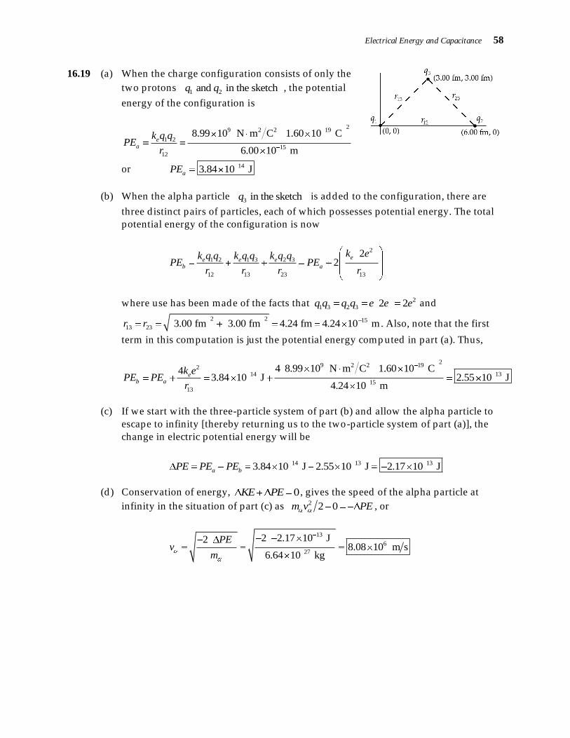
16.19 (a) When the charge configuration consists of only the
two protons 1 2 and in the sketchq q , the potential
energy of the configuration is
2
9 2 2 19
1 2
15
12
8.99 10 N m C 1.60 10 C
6.00 10 m
ea
k q qPE
r
or 143.84 10 JaPE
(b) When the alpha particle 3 in the sketchq is added to the configuration, there are
three d istinct pairs of particles, each of which possesses potential energy. The total
potential energy of the configuration is now
2
1 2 1 3 2 3
12 13 23 13
22
ee e eb a
k ek q q k q q k q qPE PE
r r r r
where use has been made of the facts that 2
1 3 2 3 2 2q q q q e e e and
2 2 15
13 23 3.00 fm 3.00 fm 4.24 fm 4.24 10 mr r . Also, note that the first
term in this computation is just the potential energy comp uted in part (a). Thus,
29 2 2 192
14 13
15
13
4 8.99 10 N m C 1.60 10 C43.84 10 J 2.55 10 J
4.24 10 m
eb a
k ePE PE
r
(c) If we start with the three-particle system of part (b) and allow the alpha particle to
escape to infinity [thereby returning us to the two-particle system of part (a)], the
change in electric potential energy will be
14 13 133.84 10 J 2.55 10 J 2.17 10 Ja bPE PE PE
(d) Conservation of energy, 0KE PE , gives the speed of the alpha particle at
infinity in the situation of part (c) as 2 2 0m v PE , or
13
6
27
2 2.17 10 J28.08 10 m s
6.64 10 kg
PEv
m

Electrical Energy and Capacitance 59
(e) When, starting with the three-particle system, the two protons are both allowed to
escape to infinity, there will be no remaining pairs of particles and hence no
remaining potential energy. Thus, 0 b bPE PE PE , and conservation of energy
gives the change in kinetic energy as bKE PE PE . Since the protons are
identical particles, this increase in kinetic energy is split equally between them
giving
21 1
2 2proton p p bKE m v PE
or 13
7
-27
2.55 10 J1.24 10 m s
1.67 10 kg
bp
p
PEv
m
16.20 (a) If a proton and an alpha particle, initially at rest 4.00 fm apart, are released and
allowed to recede to infinity, the final speeds of the two particles will d iffer because
of the d ifference in the masses of the particles. Thus, attempting to solve for the
final speeds by use of conservation of energy alone leads to a situation of having
one equation with two unknowns , and does not permit a solution.
(b) In the situation described in part (a) above, one can obtain a second equation with
the two unknown final speeds by using conservation of linear momentum. Then, one
would have two equations which could be solved simultaneously both unknowns.
(c) From conservation of energy: 2 21 1
0 0 02 2
e p
p p
i
k q qm v m v
r
or
9 2 2 19 19
2 2
15
2 8.99 10 N m C 3.20 10 C 1.60 10 C2
4.00 10 m
e p
p p
i
k q qm v m v
r
yield ing 2 2 132.30 10 Jp pm v m v [1]
From conservation of linear momentum,
0p pm v m v or p
p
mv v
m [2]
Substituting Equation [2] into Equation [1] gives
2
2 2 132.30 10 Jp
p p p
mm v m v
m or
2 131 2.30 10 Jp
p p
mm v
m

Electrical Energy and Capacitance 60
and
13 137
27 27 27
2.30 10 J 2.30 10 J1.05 10 m s
1 1.67 10 6.64 10 +1 1.67 10 kgp
p p
vm m m
Then, Equation [2] gives the final speed of the alpha particle as
27
7 6
27
1.67 10 kg1.05 10 m s 2.64 10 m s
6.64 10 kg
p
p
mv v
m
16.21 ek QV
r so
9 2 2 98.99 10 N m C 8.00 10 C 71.9 V mek Qr
V V V
For 100 V, 50.0 V, and 25.0 V, V 0.719 m, 1.44 m, and 2.88 mr
The radii are inversely proportional to the potential.
16.22 By definition, the work required to move a charge from one point to any other point on
an equipotential surface is zero. From the definition of work, cosW F s , the work
is zero only if 0s or cos 0F . The d isplacement s cannot be assumed to be zero in
all cases. Thus, one must require that cos 0F . The force F is given by F qE and
neither the charge q nor the field strength E can be assumed to be zero in all cases.
Therefore, the only way the work can be zero in all cases is if cos 0 . But if cos 0 ,
then 90 or the force (and hence the electric field) must be perpendicular to the
d isplacement s (which is tangent to the surface). That is, the field must be
perpendicular to the equipotential surface at all points on that surface.
16.23 From conservation of energy, e ef iKE PE KE PE , which gives
21
0 02
ei
f
k Qqm v
r or
2 2
2 79 22 eef
i i
k e ek Qqr
m v m v
22
9 19
2
14
227 7
N m2 8.99 10 158 1.60 10 C
C2.74 10 m
6.64 10 kg 2.00 10 m sfr

Electrical Energy and Capacitance 61
16.24 (a) The d istance from any one of the corners of the square to the point at the center is
one half the length of the d iagonal of the square, or
2 2 2
2 2 2 2
diagonal a a a ar
Since the charges have equal magnitudes and are all the same distance from the
center of the square, they make equal contributions to the total potential. Thus,
total singlecharge
4 4 4 4 22
e ee
k Q k Q QV V k
r aa
(b) The work required to carry charge q from infinity to the point at the center of the
square is equal to the increase in the electric potential energy of the charge, or
center total 0 4 2 4 2e e
Q qQW PE PE qV q k k
a a
16.25 (a)
6 2212 8
0 2
1.0 10 mC8.85 10 1.1 10 F
800 mN m
AC
d
(b) max maxmax
8 61.11 10 F 3.0 10 N C 800 m 27 C
Q C V C E d
16.26 (a) 27.0 C
3.00 F9.00 V
QC
V
(b) Q C V
16.27 (a) The capacitance of this air filled dielectric constant, 1.00 parallel plate capacitor
is
3
40 40.0 F 50.0 V 2.00 10 C 2.00 mCQ
(b) eq 1 2 25.0 F+40.0 F 65.0 FC C C
(c) 3 3
40 25 2.00 10 C 1.25 10 C 750 CQ Q Q

Electrical Energy and Capacitance 62
16.28 (a) eq
750 C11.5 V
65.0 F
QV
C
(b) 6 64.00 10 F 1.50 V 6.00 10 C 6.00 CQ C V
16.29 (a) 40 25 750 C 288 C 462 CQ Q Q d irected toward the negative plate
(b)
12 2 2 4 2
0
-3
8.85 10 C N m 7.60 10 m
1.80 10 m
AC
d
1 3 2 3.33 F 2.00 F 8.66 Fp s sC C C C
(c) 2 2 2 2 10.0 F 20.0 FpC C C on one plate and
1 1
eq
1 2
1 1 1 16.04 F
8.66 F 20.0 Fp p
CC C
on the other plate.
16.30 total eq 6.04 F 60.0 V 362 Cab
Q C V , so
12 2 2 12 2
90
-15
8.85 10 C N m 21.0 10 m3.10 10 m
60.0 10 F
Ad
C
1
11
362 C41.8 V
8.66 F
p
pp
QV
C
16.31 (a) Assuming the capacitor is air-filled 1 , the capacitance is
3 3 12.00 F 41.8 V 83.6 C
pQ C V
(b) Q C V
(c) 1 1.00 F 10.0 V 10.0 CQ
(d) 2 2.00 F 0 0Q
(e) Increasing the d istance separating the plates decreases the capacitance, the charge
stored , and the electric field strength between the plates. This means that all of the
previous answers will be decreased.

Electrical Energy and Capacitance 63
16.32 2 12Q Q
0 sin15.0 tan15.0xF qE T mg
or 1 12 10.0 CQ Q
tan15.0mgd
V Edq
6 2
3
9
350 10 kg 9.80 m s 0.040 0 m tan15.01.23 10 V 1.23 kV
30.0 10 CV
16.33 (a) Capacitors in a series combination store the same charge, 7.00 F and the 5.00 F,
where eqC is the equivalent capacitance and 4.00 F is the potential d ifference
maintained across the series combination. The equivalent capacitance for the given
series combination is eq 1 2
1 1 1
C C C, or 1 2
eq
1 2
C CC
C C, giving
2
2 26 41 1Energy stored 4.50 10 F 12.0 V 3.24 10 J
2 2 2
QC V
C
so the charge stored on each capacitor in the series combination is
eq 1.79 F 6.00 V 10.7 CQ C V
(b) When connected in parallel, each capacitor has the same potential difference,
eq
1 1 1 2 1
18.0 F 36.0 F 36.0 FC, maintained across it. The charge stored on each
capacitor is then
For 1 2.50 FC : 1 1 2.50 F 6.00 V 15.0 CQ C V
For 2 6.25 FC : 2 2 6.25 F 6.00 V 37.5 CQ C V
16.34 (a) When connected in series, the equivalent capacitance is eq 1 2
1 1 1
C C C, or
1 2eq
1 2
4.20 F 8.50 F2.81 F
4.20 F 8.50 F
C CC
C C

Electrical Energy and Capacitance 64
(b) When connected in parallel, the equivalent capacitance is
if the computed equivalent capacitance is truly equivalent to the original combination.
16.35 (a) First, we replace the parallel combination
between points b and c by its equivalent
capacitance, 2.00 F 6.00 F 8.00 FbcC .
Then, we have three capacitors in series
between points a and d . The equivalent
capacitance for this circuit is therefore
eq ab bc cd
1 1 1 1 3
8.00 FC C C C
giving eq
8.00 F2.67 F
3C
(b) The charge store on each capacitor in the series combination is
ab bc cd eq ad 2.67 F 9.00 V 24.0 CQ Q Q C V
Then, note that bcbc
bc
24.0 C3.00 V
8.00 F
QV
C. The charge on each capacitor in the
original circuit is:
On the 8.00 F between a and b: 8 ab 24.0 CQ Q
On the 8.00 F between c and d : 8 cd 24.0 CQ Q
On the 2.00 F between b and c: 2 2 bc 2.00 F 3.00 V 6.00 CQ C V
On the 6.00 F between b and c: 6 6 bc 6.00 F 3.00 V 18.0 CQ C V
(c) Note that 2 2
3
1 1Energy stored 1.50 F 6.00 V 27.0 J
2 2f i
C V , and that
8
750.0 C 1.00 10 V1 1
2.50 10 J100 2 200
W Q V . We earlier found that
bc 3.00 VV , so we conclude that the potential d ifference across each capacitor in
the circuit is
8 2 6 8 3.00 VV V V V

Electrical Energy and Capacitance 65
16.36 0Q [1]
V Q C
Thus, using Equation [1], 2 2
series
2 2
9.00 pF 2.00 pF
9.00 pF
C CC
C C which reduces to
22
2 29.00 pF 18.0 pF 0C C , or nylon
Therefore, either 2 6.00 pFC and , from Equation [1], 3.40
or 85.0 Vi
V and 1 6.00 pFC .
We conclude that the two capacitances are 3.00 pF and 6.00 pF .
16.37 (a) The equivalent capacitance of the series combination
in the upper branch is
370 pCfQ
or 80 See Table 16.1
Likewise, the equivalent capacitance of the series combination in the lower branch
is
0 80 1.48 pF 118 pFfC C or lower 1.33 FC
These two equivalent capacitances are connected in parallel with each other, so the
equivalent capacitance for the entire circuit is
eq upper lowerC 2.00 F 1.33 F 3.33 FC C
Electrical Energy and Capacitance 66
(b) Note that the same potential d ifference, equal to the potential d ifference of the
battery, exists across both the upper and lower branches. The charge stored on each
capacitor in the series combination in the upper branch is
3 6 upper upper 2.00 F 90.0 V 180 CQ Q Q C V
and , the charge stored on each capacitor in the series combination in the lower
branch is
12 2 2 4 2
0
-3
2.1 8.85 10 C N m 175 10 m
0.040 0 10 m
AC
d
(c) The potential d ifference across each of the capacitors in the circuit is:
22
2
120 C60.0 V
2.00 F
QV
C 4
4
4
120 C30.0 V
4.00 F
QV
C
33
3
180 C60.0 V
3.00 F
QV
C
00w LA
Cd d
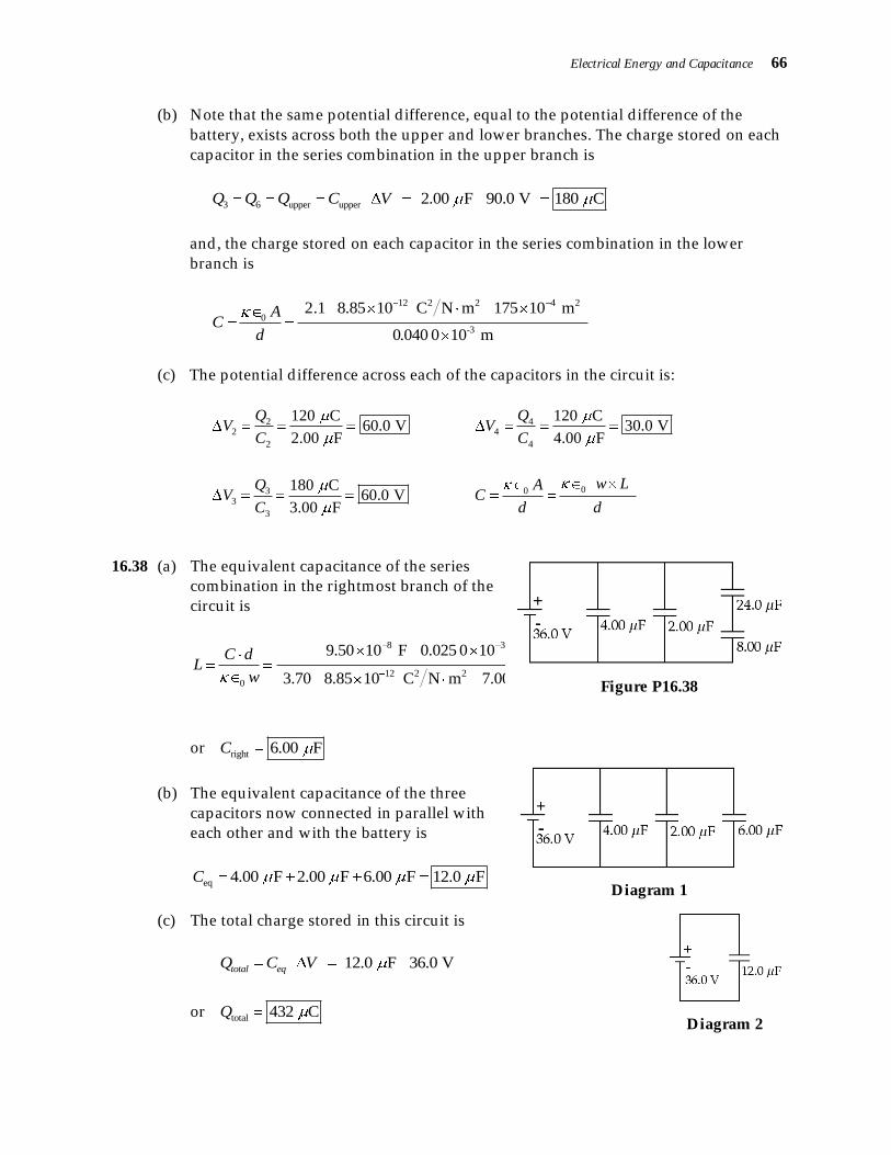
16.38 (a) The equivalent capacitance of the series
combination in the rightmost branch of the
circuit is
8 3
12 2 2 20
9.50 10 F 0.025 0 10 m1.04 m
3.70 8.85 10 C N m 7.00 10 m
C dL
w
or right 6.00 FC
Figure P16.38
(b) The equivalent capacitance of the three
capacitors now connected in parallel with
each other and with the battery is
eq 4.00 F 2.00 F 6.00 F 12.0 FC
Diagram 1
(c) The total charge stored in this circuit is
12.0 F 36.0 Vtotal eqQ C V
or total 432 CQ
Diagram 2

Electrical Energy and Capacitance 67
(d) The charges on the three capacitors shown in Diagram 1 are:
13 -3 142.01 10 F 100 10 V 2.01 10 CQ C V
14
5
-19
2.01 10 C1.26 10
1.60 10 C
Qn
e
right right 6.00 F 36.0 V 216 CQ C V
4 2Yes. as it should.right totalQ Q Q Q
(e) The charge on each capacitor in the series combination in the rightmost branch of
the original circuit (Figure P16.38) is
0eq 1 2 3 where
AC d d d d
d
(f) eqC 3.33 F
(g) 88
8
216 C27.0 V
8.00 F
QV
C Note that
8 24 36.0 VV V V as it should .
16.39
The circuit may be reduced in steps as shown above.
Using the Figure 3, 4.00 F 24.0 V 96.0 CacQ
Then, in Figure 2, 96.0 C
16.0 V6.00 F
ac
abab
QV
C
and 24.0 V 16.0 V 8.00 Vbc ac ab
V V V

Electrical Energy and Capacitance 68
Finally, using Figure 1, 1 1 1.00 F 16.0 V 16.0 Cab
Q C V
262
34
4 64
120 10 CEnergy stored 1.80 10 J 1.80 mJ
2 2 4.00 10 F
Q
C, 6.00 F
and 4 4.00 F 32.0 Cbc
Q V
16.40 From Q C V , the initial charge of each capacitor is
10 10.0 F 12.0 V 120 CQ and
2C
After the capacitors are connected in parallel, the potential d ifference across each is
3.00 VV , and the total charge of 10 120 CxQ Q Q is d ivided between the two
capacitors as
10 10.0 F 3.00 V 30.0 CQ and
10 120 C 30.0 C 90.0 CxQ Q Q
Thus, 90.0 C
30.0 F3.00 V
xx
QC
V
16.41 (a) From Q C V , 3
25 25.0 F 50.0 V 1.25 10 C 1.25 mCQ
and 3
40 40.0 F 50.0 V 2.00 10 C 2.00 mCQ
(b) When the two capacitors are connected in parallel, the equivalent capacitance is
eq 1 2 25.0 F+40.0 F 65.0 FC C C .
Since the negative plate of one was connected to the positive plate of the other, the
total charge stored in the parallel combination is
3 3
40 25 2.00 10 C 1.25 10 C 750 CQ Q Q
The potential d ifference across each capacitor of the parallel combination is
eq
750 C11.5 V
65.0 F
QV
C

Electrical Energy and Capacitance 69
and the final charge stored in each capacitor is
25 1 25.0 F 11.5 V 288 CQ C V
and 40 25 750 C 288 C 462 CQ Q Q
16.42 (a) The original circuit reduces to a single equivalent capacitor in the steps shown
below.
1 1
1 2
1 1 1 13.33 F
5.00 F 10.0 FsC
C C
1 3 2 3.33 F 2.00 F 8.66 Fp s sC C C C
2 2 2 2 10.0 F 20.0 FpC C C
1 1
eq
1 2
1 1 1 16.04 F
8.66 F 20.0 Fp p
CC C
Electrical Energy and Capacitance 70
(b) The total charge stored between points a and b is
total eq 6.04 F 60.0 V 362 Cab
Q C V
Then, looking at the third figure, observe that the charges of the series capacitors of
that figure are 1 2 total 362 Cp pQ Q Q . Thus, the potential d ifference across the
upper parallel combination shown in the second figure is
1
11
362 C41.8 V
8.66 F
p
pp
QV
C
Finally, the charge on 3C is
3 3 12.00 F 41.8 V 83.6 C
pQ C V
16.43 From Q C V , the initial charge of each capacitor is
1 1.00 F 10.0 V 10.0 CQ and
2 2.00 F 0 0Q
After the capacitors are connected in parallel, the potential d ifference across one is the
same as that across the other. This gives
1 2
1.00 F 2.00 F
Q QV or
2 12Q Q [1]
From conservation of charge, 1 2 1 2 10.0 CQ Q Q Q . Then, substituting from
Equation [1], this becomes
1 12 10.0 CQ Q , giving 1
10 C
3Q
Finally, from Equation [1], 2
20 C
3Q

Electrical Energy and Capacitance 71
16.44 Recognize that the 7.00 F and the 5.00 F of the
center branch are connected in series. The total
capacitance of that branch is
11 1
2.92 F5.00 7.00
sC
Then recognize that this capacitor, the 4.00 F
capacitor, and the 6.00 F capacitor are all connected
in parallel between points a and b. Thus, the equivalent
capacitance between points a and b is
eq 4.00 F 2.92 F+6.00 F 12.9 FC
16.45 2
2 26 41 1Energy stored 4.50 10 F 12.0 V 3.24 10 J
2 2 2
QC V
C
16.46 (a) The equivalent capacitance of a series combination of 1 2 and C C is
eq
1 1 1 2 1
18.0 F 36.0 F 36.0 FC or eq 12.0 FC
When this series combination is connected to a 12.0-V battery, the total stored
energy is
2 26 4
eq
1 1Total energy stored 12.0 10 F 12.0 V 8.64 10 J
2 2C V
(b) The charge stored on each of the two capacitors in the series combination is
4
1 2 total eq 12.0 F 12.0 V 144 C 1.44 10 CQ Q Q C V
and the energy stored in each of the individual capacitors is
242
411 6
1
1.44 10 CEnergy stored in 5.76 10 J
2 2 18.0 10 F
QC
C
and
242
422 6
2
1.44 10 CEnergy stored in 2.88 10 J
2 2 36.0 10 F
QC
C

Electrical Energy and Capacitance 72
4 4 4
1 2Energy stored in Energy stored in 5.76 10 J 2.88 10 J 8.64 10 JC C , which
is the same as the total stored energy found in part (a). This must be true
if the computed equivalent capacitance is truly equivalent to the original combination.
(c) If 1 2 and C C had been connected in parallel rather than in series, the equivalent
capacitance would have been eq 1 2 18.0 F 36.0 F 54.0 FC C C . If the total
energy stored 2
eq
1
2C V in this parallel combination is to be the same as was
stored in the original series combination, it is necessary that
4
6
eq
2 8.64 10 J2 Total energy stored5.66 V
54.0 10 FV
C
Since the two capacitors in parallel have the same potential d iffer ence across them,
the energy stored in the individual capacitors 21
2C V is d irectly proportional
to their capacitances. 2The larger capacitor, , stores the most energy in this case.C
16.47 (a) The energy initially stored in the capacitor is
2
2 2
1
1 1Energy stored 3.00 F 6.00 V 54.0 J
2 2 2
ii i
i
QC V
C
(b) When the capacitor is d isconnected from the battery, the stored charge becomes
isolated with no way off the plates. Thus, the charge remains constant at the value
iQ as long as the capacitor remains d isconnected . Since the capacitance of a parallel
plate capacitor is e0C A d , when the d istance d separating the plates is doubled ,
the capacitance is decreased by a factor of 2 2 1.50 Ff iC C . The stored energy
(with Q unchanged) becomes
2 2 2
2 1Energy stored 2 2 Energy stored 108 J
2 2 2 2
i i i
f i f
Q Q Q
C C C
(c) When the capacitor is reconnected to the battery, the potential d ifference between
the plates is reestablished at the original value of 6.00 Vi
V V , while the
capacitance remains at 2 1.50 Ff iC C . The energy stored under these
conditions is
2 2
3
1 1Energy stored 1.50 F 6.00 V 27.0 J
2 2f i
C V

Electrical Energy and Capacitance 73
16.48 The energy transferred to the water is
8
750.0 C 1.00 10 V1 1
2.50 10 J100 2 200
W Q V
Thus, if m is the mass of water boiled away,
vW m c T L becomes
7 6J2.50 10 J 4186 100 C 30.0 C 2.26 10 J kg
kg Cm
giving 72.50 10 J
9.79 kg2.55 J kg
m
16.49 (a) Note that the charge on the plates remains constant at the original value, 0Q , as the
d ielectric is inserted . Thus, the change in the potential d ifference, V Q C , is due
to a change in capacitance alone. The ratio of the final and initial capacitances is
0
0
f
i
C A d
C A d and
0
0
85.0 V3.40
25.0 V
f f i
i i f
Q V VC
C Q V V
Thus, the d ielectric constant of the inserted material is 3.40 , and the material is
probably nylon (see Table 16.1).
(b) If the d ielectric only partially filled the space between the plates, leaving the
remaining space air-filled , the equivalent d ielectric constant would be somewhere
between 1.00 (air) and 3.40 . The resulting potential d ifference would then
lie somewhere between 85.0 Vi
V and 25.0 Vf
V .

Electrical Energy and Capacitance 74
16.50 (a) The capacitance of the capacitor while air-filled is
12 2 2 4 2
1200 2
8.85 10 C N m 25.0 10 m1.48 10 F 1.48 pF
1.50 10 m
AC
d
The original charge stored on the plates is
-12 2 12
0 0 01.48 10 F 2.50 10 V 370 10 C 370 pCQ C V
Since d istilled water is an insulator, introducing it between the isolated capacitor
plates does not allow the charge to change. Thus, the final charge is 370 pCfQ .
(b) After immersion d istilled water 80 See Table 16.1 , the new capacitance is
0 80 1.48 pF 118 pFfC C
and the new potential d ifference is 370 pC
3.14 V118 pF
f
ff
QV
C
(c) The energy stored in a capacitor is: 2Energy stored 2Q C . Thus, the change in the
stored energy due to immersion in the d istilled water is
2122 2 2
0 0
12 12
8 9
370 10 C1 1 1 1E
2 2 2 2 118 10 F 1.48 10 F
4.57 10 J 45.7 10 J 45.7 nJ
f
f i f i
Q Q Q
C C C C
16.51 (a) The d ielectric constant for Teflon ® is 2.1 , so the capacitance is
12 2 2 4 2
0
-3
2.1 8.85 10 C N m 175 10 m
0.040 0 10 m
AC
d
98.13 10 F 8.13 nFC
(b) For Teflon®, the d ielectric strength is 660.0 10 V mmaxE , so the maximum voltage
is
6 -3
max max 60.0 10 V m 0.040 0 10 m V E d
3
max 2.40 10 V 2.40 kVV

Electrical Energy and Capacitance 75
16.52 Before the capacitor is rolled , the capacitance of this parallel plate capacitor is
00
w LAC
d d
where A is the surface area of one side of a foil strip. Thus, the required length is
8 3
12 2 2 20
9.50 10 F 0.025 0 10 m1.04 m
3.70 8.85 10 C N m 7.00 10 m
C dL
w
16.53 (a) 12
16 3
3
1.00 10 kg9.09 10 m
1100 kg m
mV
Since 34
3
rV , the radius is
1 33
4
Vr , and the surface area is
2 316 32 3
2 10 23 9.09 10 m3
4 4 4 4.54 10 m4 4
VA r
(b) 0 AC
d
12 2 2 10 2
13
9
5.00 8.85 10 C N m 4.54 10 m2.01 10 F
100 10 m
(c) 13 -3 142.01 10 F 100 10 V 2.01 10 CQ C V
and the number of electronic charges is
14
5
-19
2.01 10 C1.26 10
1.60 10 C
Qn
e
16.54 Since the capacitors are in parallel, the equivalent capacitance is
0 1 2 30 1 0 2 0 3
eq 1 2 3
A A AA A AC C C C
d d d d
or 0eq 1 2 3 where
AC A A A A
d

Electrical Energy and Capacitance 76
16.55 Since the capacitors are in series, the equivalent capacitance is given by
3 1 2 31 2
eq 1 2 3 0 0 0 0
1 1 1 1 d d d dd d
C C C C A A A A
or 0eq 1 2 3 where
AC d d d d
d
16.56 (a) Please refer to the solution of Problem 16.37 where the
following results were obtained:
eqC 3.33 F 3 6 180 CQ Q
2 4 120 CQ Q
The total energy stored in the full circuit is then
2 26
eqtotal
2 3
1 1Energy stored C 3.33 10 F 90.0 V
2 2
1.35 10 J 13.5 10 J 13.5 mJ
V
(b) The energy stored in each individual capacitor is
For 2.00 F:
262
32
2 62
120 10 CEnergy stored 3.60 10 J 3.60 mJ
2 2 2.00 10 F
Q
C
For 3.00 F :
262
33
3 63
180 10 CEnergy stored 5.40 10 J 5.40 mJ
2 2 3.00 10 F
Q
C
For 4.00 F:
262
34
4 64
120 10 CEnergy stored 1.80 10 J 1.80 mJ
2 2 4.00 10 F
Q
C
For 6.00 F :
262
36
6 66
180 10 CEnergy stored 2.70 10 J 2.70 mJ
2 2 6.00 10 F
Q
C
(c) The total energy stored in the individual capacitors is
totalEnergy stored= 3.60 5.40 1.80 2.70 mJ 13.5 mJ Energy stored
Thus, the sums of the energies stored in the individual capacitors equals the total
energy stored by the system.

Electrical Energy and Capacitance 77
Electrical Energy and Capacitance 78
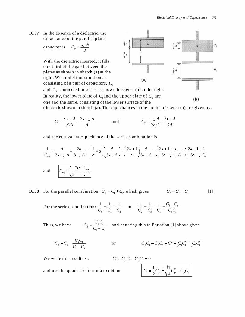
16.57 In the absence of a d ielectric, the
capacitance of the parallel plate
capacitor is 00
AC
d
With the d ielectric inserted , it fills
one-third of the gap between the
plates as shown in sketch (a) at the
right. We model this situation as
consisting of a pair of capacitors, 1C
(a)
(b)
and 2C , connected in series as shown in sketch (b) at the right.
In reality, the lower plate of 1C and the upper plate of
2C are
one and the same, consisting of the lower surface of the
dielectric shown in sketch (a). The capacitances in the model of sketch (b) are given by:
0 01
3
3
A AC
d d and 0 0
2
3
2 3 2
A AC
d d
and the equivalent capacitance of the series combination is
0 0 0 0 0 0
1 2 1 2 1 2 1 2 1 12
3 3 3 3 3 3eq
d d d d d
C A A A A A C
and eq 0
3
2 1C C
16.58 For the parallel combination: 1 2pC C C which gives 2 1pC C C [1]
For the series combination: 1
1 2 2 1 1
1 1 1 1 1 1 or s
s s s
C C
C C C C C C C C
Thus, we have 12
1
s
s
C CC
C C and equating this to Equation [1] above gives
11
1
sp
s
C CC C
C C or 2
1 1 1p p s sC C C C C C C 1sC C
We write this result as : 2
1 1 0p p sC C C C C
and use the quadratic formula to obtain 2
1
1 1
2 4p p p sC C C C C

Electrical Energy and Capacitance 79
Then, Equation [1] gives 2
2
1 1
2 4p p p sC C C C C
16.59 The charge stored on the capacitor by the battery is
1
100 VQ C V C
This is also the total charge stored in the parallel combination when this charged
capacitor is connected in parallel with an uncharged 10.0- F capacitor. Thus, if 2
V is
the resulting voltage across the parallel combination, 2pQ C V gives
100 V 10.0 F 30.0 VC C or 70.0 V 30.0 V 10.0 FC
and 30.0 V
10.0 F 4.29 F70.0 V
C
16.60 (a) The 1.0- C is located 0.50 m from point P, so its contribution to the potential at P is
6
9 2 2 411
1
1.0 10 C8.99 10 N m C 1.8 10 V
0.50 me
qV k
r
(b) The potential at P due to the 2.0- C charge located 0.50 m away is
6
9 2 2 422
2
2.0 10 C8.99 10 N m C 3.6 10 V
0.50 me
qV k
r
(c) The total potential at point P is 4 4
1 2 1.8 3.6 10 V 1.8 10 VPV V V
(d) The work required to move a charge 3.0 Cq to point P from infinity is
6 4 23.0 10 C 1.8 10 V 0 5.4 10 JPW q V q V V

Electrical Energy and Capacitance 80
16.61 The stages for the reduction of this circuit are shown below.
Thus, 6.25 FeqC
16.62 (a) Due to spherical symmetry, the charge on each of the concentric spherical shells will
be uniformly d istributed over that shell. Inside a spherical surface having a uniform
charge d istribution, the electric field due to the charge on that surface is zero. Thus ,
in this region, the potential due to the charge on that surface is constant and equal
to the potential at the surface. Outside a spherical surface having a uniform charge
d istribution, the potential due to the charge on that surface is given by ek qV
r
where r is the d istance from the center of that surface and q is the charge on that
surface.
In the region between a pair of concentric spherical shells, with the inner shell
having charge Q and the outer shell having radius b and charge Q , the total
electric potential is given by
due to due toinner shell outer shell
1 1eee
k Qk QV V V k Q
r b r b
The potential d ifference between the two shells is therefore,
1 1 1 1
e e er a r b
b aV V V k Q k Q k Q
a b b b ab
The capacitance of this device is given by
e
Q abC
V k b a

Electrical Energy and Capacitance 81
(b) When b a , then b a b . Thus, in the limit as b , the capacitance found
above becomes
04e e
ab aC a
k b k
16.63 The energy stored in a charged capacitor is 21
2W C V . Hence,
3
-6
2 300 J24.47 10 V 4.47 kV
30.0 10 F
WV
C
16.64 From Q C V , the capacitance of the capacitor with air between the plates is
00
150 CQC
V V
After the d ielectric is inserted , the potential d ifference is held to the original value, but
the charge changes to 0 200 C=350 CQ Q . Thus, the capacitance with the d ielectric
slab in place is
350 CQ
CV V
The d ielectric constant of the d ielectric slab is therefore
0
350 C 3502.33
150 C 150
C V
C V
16.65 The charges initially stored on the capacitors are
3
1 1 6.0 F 250 V 1.5 10 Ci
Q C V
and 2
2 2 2.0 F 250 V 5.0 10 Ci
Q C V
When the capacitors are connected in parallel, with the negative plate of one connected
to the positive plate of the other, the net stored charge is
3 2 3
1 2 1.5 10 C 5.0 10 C=1.0 10 CQ Q Q

Electrical Energy and Capacitance 82
The equivalent capacitance of the parallel combination is eq 1 2 8.0 FC C C . Thus, the
final potential d ifference across each of the capacitors is
3
eq
1.0 10 C125 V
8.0 F
QV
C
and the final charge on each capacitor is
1 1 6.0 F 125 V 750 C 0.75 mCQ C V
and 2 2 2.0 F 125 V 250 C 0.25 mCQ C V
16.66 The energy required to melt the lead sample is
Pb
6 36.00 10 kg 128 J kg C 327.3 C 20.0 C 24.5 10 J kg
0.383 J
fW m c T L
The energy stored in a capacitor is 21
2W C V , so the required potential d ifference is
-6
2 0.383 J2121 V
52.0 10 F
WV
C
16.67 When excess charge resides on a spherical surface that is far removed from any other
charge, this excess charge is uniformly d istributed over the spherical surface, an d the
electric potential at the surface is the same as if all the excess charge were concentrated
at the center of the spherical surface.
In the given situation, we have two charged spheres, initially isolated from each other,
with charges and potentials of: 1 6.00 CQ ,
1 1 1eV k Q R where 1 12.0 cmR ,
2 4.00 CQ , and 2 2 2eV k Q R with
2 18.0 cmR .

Electrical Energy and Capacitance 83
When these spheres are then connected by a long conducting thread , the charges are
redistributed 1 2yielding charges of and respectivelyQ Q until the two surfaces come to a
common potential 1 1 1 2 2 2V kQ R V kQ R . When equilibrium is established , we have:
From conservation of charge: 1 2 1 2 Q Q Q Q
1 2 2.00 CQ Q [1]
From equal potentials: 1 2 22 1
1 2 1
kQ kQ R
Q QR R R
or 2 11.50Q Q [2]
Substituting Equation [2] into [1] gives: 1
2.00 C0.800 C
2.50Q
Then, Equation [2] gives: 2 1.50 0.800 C 1.20 CQ
16.68 The electric field between the plates is d irected downward with magnitude
4
-3
100 V5.00 10 N m
2.00 10 my
VE
d
Since the gravitational force experienced by the electron is negligible in comparison to
the electrical force acting on it, the vertical acceleration is
19 4
15 2
31
1.60 10 C 5.00 10 N m8.78 10 m s
9.11 10 kg
y y
y
e e
F qEa
m m
(a) At the closest approach to the bottom plate, 0yv . Thus, the vertical displacement
from point O is found from 2 2
0 2y y yv v a y as
262
0 0
15 2
5.6 10 m s sin 450 sin0.89 mm
2 2 8.78 10 m sy
vy
a
The minimum distance above the bottom plate is then
1.00 mm 0.89 mm 0.11 mm2
Dd y

Electrical Energy and Capacitance 84
(b) The time for the electron to go from point O to the upper plate is found from
2
0
1
2y yy v t a t as
3 6 15 2
2
m 1 m1.00 10 m 5.6 10 sin 45 8.78 10
s 2 st t
Solving for t gives a positive solution of 91.11 10 st . The horizontal
d isplacement from point O at this time is
6 9
0 5.6 10 m s cos45 1.11 10 s 4.4 mmxx v t