Embed Size (px)
Citation preview
Electrical Engineering Department
Basic Electrical Engineering Laboratory
EENUGES02
EENUGES02
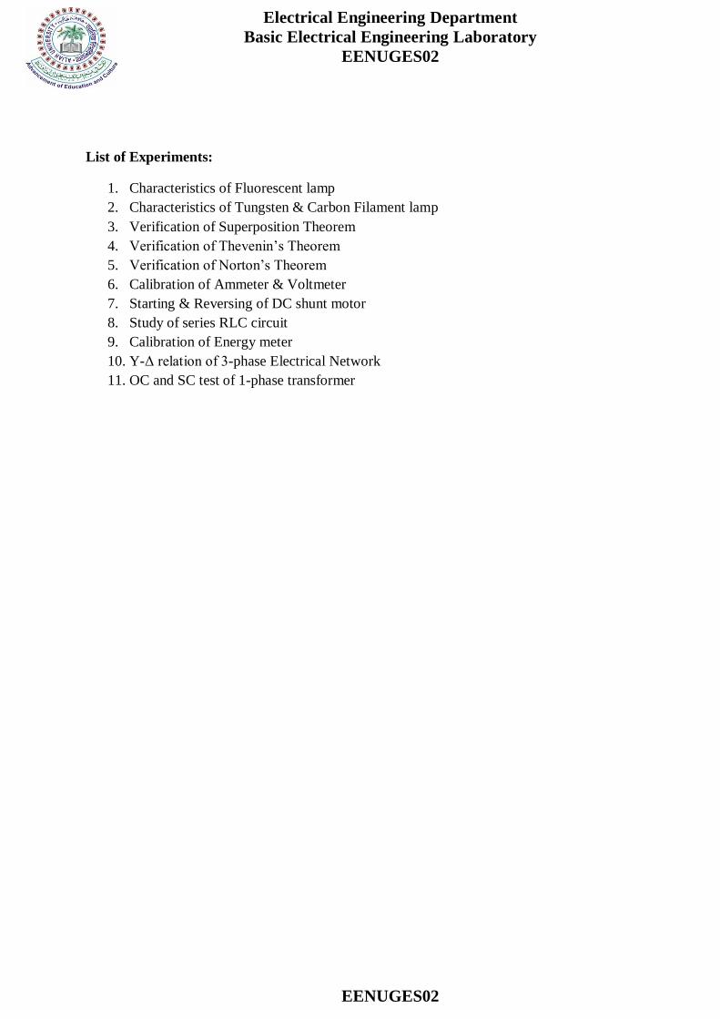
List of Experiments:
1. Characteristics of Fluorescent lamp
2. Characteristics of Tungsten & Carbon Filament lamp
3. Verification of Superposition Theorem
4. Verification of Thevenin’s Theorem
5. Verification of Norton’s Theorem
6. Calibration of Ammeter & Voltmeter
7. Starting & Reversing of DC shunt motor
8. Study of series RLC circuit
9. Calibration of Energy meter
10. Y-Δ relation of 3-phase Electrical Network
11. OC and SC test of 1-phase transformer
Electrical Engineering Department
Basic Electrical Engineering Laboratory
EENUGES02
EENUGES02
Experiment no: 1
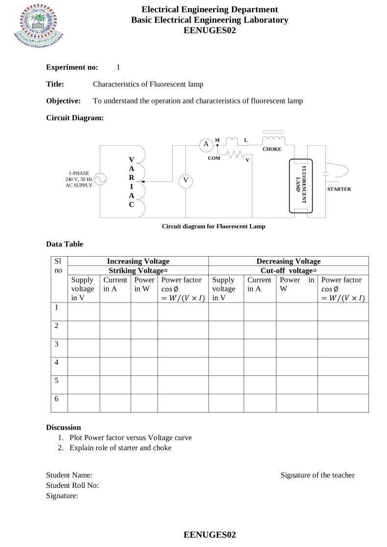
Title: Characteristics of Fluorescent lamp
Objective: To understand the operation and characteristics of fluorescent lamp
Circuit Diagram:
1-PHASE
240 V, 50 Hz
AC SUPPLY
A
V
V
A
R
I
A
C
M L
COM V
CHOKE
STARTER
FL
UO
RE
SC
EN
T
LA
MP
Circuit diagram for Fluorescent Lamp
Data Table
Sl
no
Increasing Voltage Decreasing Voltage
Striking Voltage= Cut-off voltage=
Supply
voltage
in V
Current
in A
Power
in W
Power factor
cos∅= 𝑊 (𝑉 × 𝐼)
Supply
voltage
in V
Current
in A
Power in
W
Power factor
cos∅= 𝑊 (𝑉 × 𝐼)
1
2
3
4
5
6
Discussion
1. Plot Power factor versus Voltage curve
2. Explain role of starter and choke
Student Name: Signature of the teacher
Student Roll No:
Signature:
Electrical Engineering Department
Basic Electrical Engineering Laboratory
EENUGES02
EENUGES02
Experiment no: 2
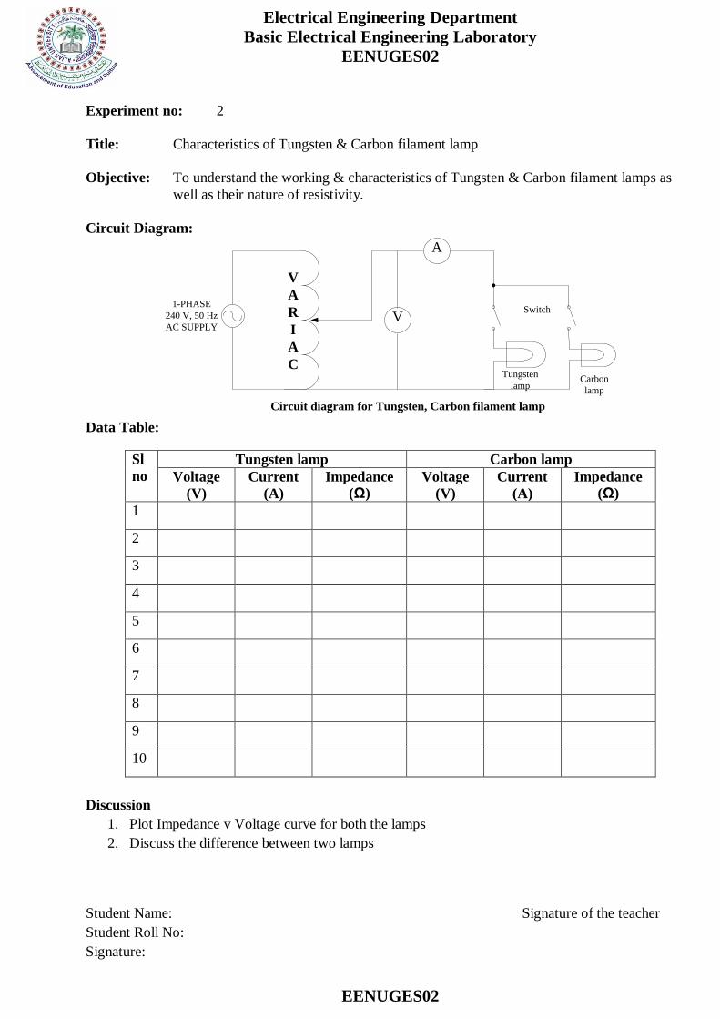
Title: Characteristics of Tungsten & Carbon filament lamp
Objective: To understand the working & characteristics of Tungsten & Carbon filament lamps as
well as their nature of resistivity.
Circuit Diagram:
1-PHASE
240 V, 50 Hz
AC SUPPLY
A
V
Tungsten
lampCarbon
lamp
V
A
R
I
A
C
Switch
Circuit diagram for Tungsten, Carbon filament lamp Data Table:
Sl
no
Tungsten lamp Carbon lamp
Voltage
(V)
Current
(A)
Impedance
(Ω)
Voltage
(V)
Current
(A)
Impedance
(Ω)
1
2
3
4
5
6
7
8
9
10
Discussion
1. Plot Impedance v Voltage curve for both the lamps
2. Discuss the difference between two lamps
Student Name: Signature of the teacher
Student Roll No:
Signature:
Electrical Engineering Department
Basic Electrical Engineering Laboratory
EENUGES02
EENUGES02
Experiment no: 3
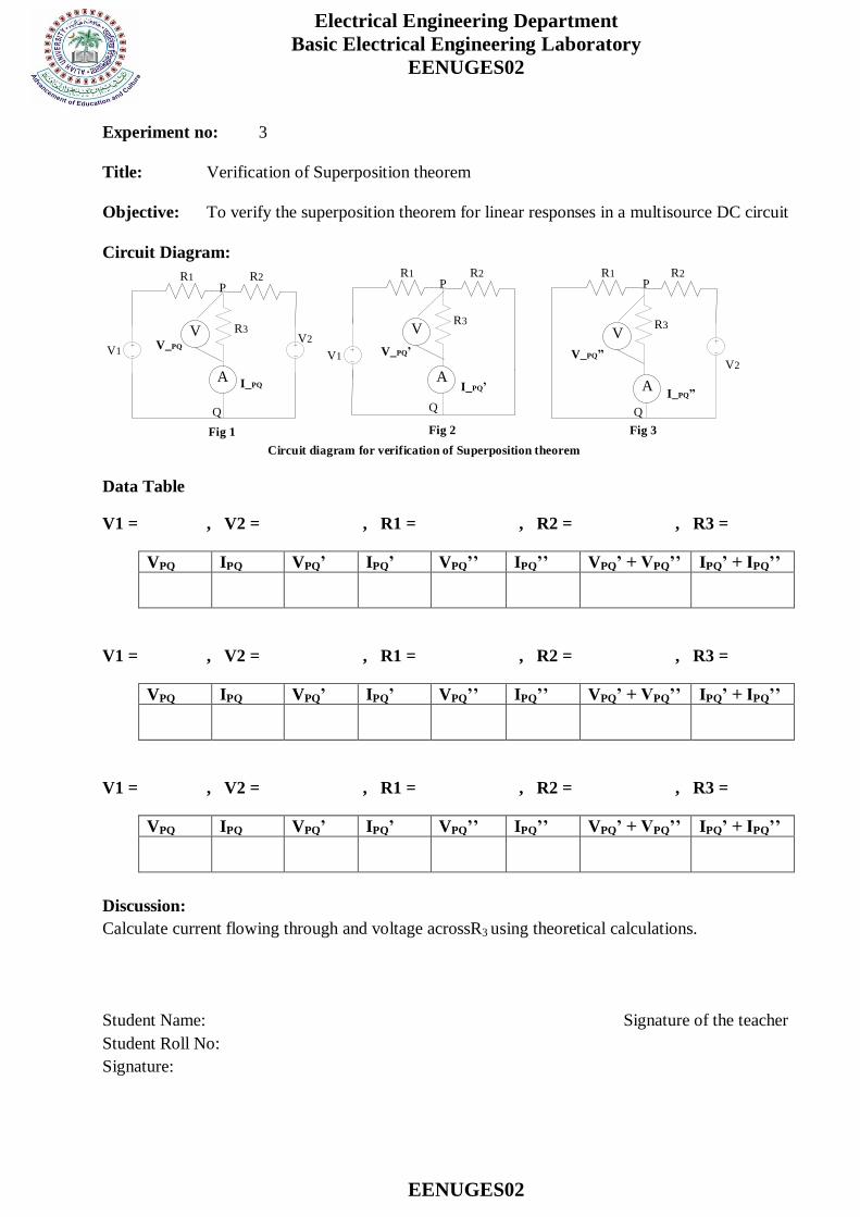
Title: Verification of Superposition theorem
Objective: To verify the superposition theorem for linear responses in a multisource DC circuit
Circuit Diagram:
V1
A
V2
R1 R2
R3
Fig 1
V1
A
R1 R2
R3
Fig 2
A
R1 R2
R3
Fig 3
V2
Circuit diagram for verification of Superposition theorem
V V V
P P P
Q Q Q
V_PQV_PQ V_PQ
I_PQ I_PQ I_PQ
Data Table
V1 = , V2 = , R1 = , R2 = , R3 =
VPQ IPQ VPQ’ IPQ’ VPQ’’ IPQ’’ VPQ’ + VPQ’’ IPQ’ + IPQ’’
V1 = , V2 = , R1 = , R2 = , R3 =
VPQ IPQ VPQ’ IPQ’ VPQ’’ IPQ’’ VPQ’ + VPQ’’ IPQ’ + IPQ’’
V1 = , V2 = , R1 = , R2 = , R3 =
VPQ IPQ VPQ’ IPQ’ VPQ’’ IPQ’’ VPQ’ + VPQ’’ IPQ’ + IPQ’’
Discussion:
Calculate current flowing through and voltage acrossR3 using theoretical calculations.
Student Name: Signature of the teacher
Student Roll No:
Signature:

Electrical Engineering Department
Basic Electrical Engineering Laboratory
EENUGES02
EENUGES02
Experiment no: 4
Title: Verification of Thevenin’s theorem
Objective: To verify the Thevenin’s Theorem in a linear DC circuit.
Circuit Diagram:
V1
A
V2
R1 R2
R3
Fig 1
V1
Eth
R1 R2
Fig 2
Circuit diagram for verification of Thevenin s theorem
R1 R2
Rth
Fig 3
Eth
Rth
Fig 4
R3
I
V2
Data table
V1 =
As per Fig 1:
Imeasured=
Verification
As per Fig 4
Iverified= Eth /(Rth + R3)
% Error= 100 ×(Imeasured – Iverifired)/
Imeasured V2 =
R1 =
As per Fig 2:
Eth =
R2 =
R3 = As per Fig 3:
Rth=
Discussion:
Verify all steps through theoretical calculations.
Student Name: Signature of the teacher
Student Roll No:
Signature:
Electrical Engineering Department
Basic Electrical Engineering Laboratory
EENUGES02
EENUGES02
Experiment no: 5
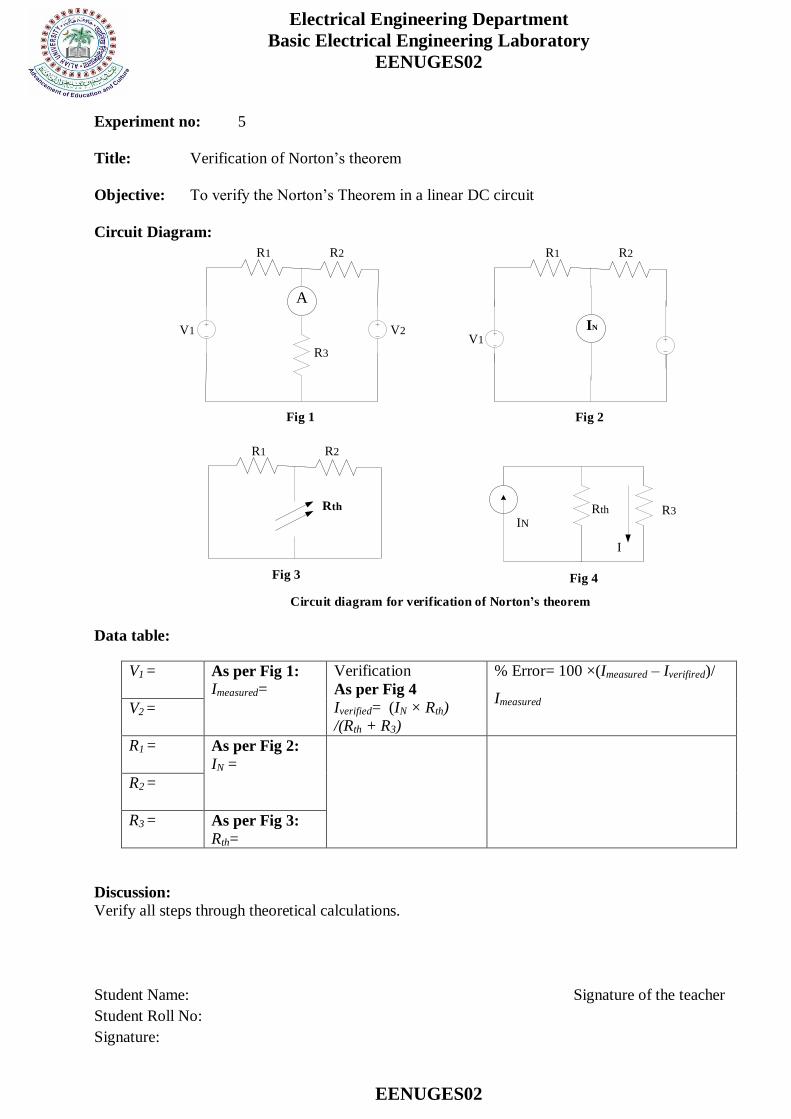
Title: Verification of Norton’s theorem
Objective: To verify the Norton’s Theorem in a linear DC circuit
Circuit Diagram:
V1
A
V2
R1 R2
R3
Fig 1
V1
IN
R1 R2
Fig 2
Circuit diagram for verification of Norton s theorem
R1 R2
Rth
Fig 3
Rth
Fig 4
R3
I
IN
Data table:
V1 =
As per Fig 1:
Imeasured=
Verification
As per Fig 4
Iverified= (IN × Rth)
/(Rth + R3)
% Error= 100 ×(Imeasured – Iverifired)/
Imeasured V2 =
R1 =
As per Fig 2:
IN =
R2 =
R3 = As per Fig 3:
Rth=
Discussion:
Verify all steps through theoretical calculations.
Student Name: Signature of the teacher
Student Roll No:
Signature:
Electrical Engineering Department
Basic Electrical Engineering Laboratory
EENUGES02
EENUGES02
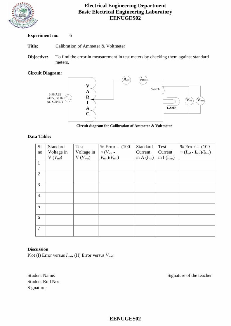
Experiment no: 6
Title: Calibration of Ammeter & Voltmeter
Objective: To find the error in measurement in test meters by checking them against standard
meters.
Circuit Diagram:
1-PHASE
240 V, 50 Hz
AC SUPPLY
Astd
Vstd
LAMP
V
A
R
I
A
C
Switch
Circuit diagram for Calibration of Ammeter & Voltmeter
Atest
Vtest
Data Table:
Sl
no
Standard
Voltage in
V (Vstd)
Test
Voltage in
V (Vtest)
% Error = (100
× (Vstd -
Vtest)/Vtest)
Standard
Current
in A (Istd)
Test
Current
in I (Itest)
% Error = (100
× (Istd - Itest)/Itest)
1
2
3
4
5
6
7
Discussion
Plot (I) Error versus Itest, (II) Error versus Vtest.
Student Name: Signature of the teacher
Student Roll No:
Signature:
Electrical Engineering Department
Basic Electrical Engineering Laboratory
EENUGES02
EENUGES02
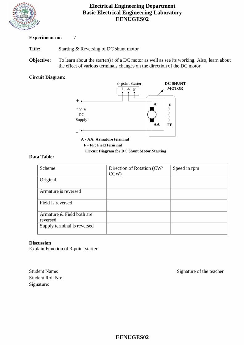
Experiment no: 7
Title: Starting & Reversing of DC shunt motor
Objective: To learn about the starter(s) of a DC motor as well as see its working. Also, learn about
the effect of various terminals changes on the direction of the DC motor.
Circuit Diagram:
L A F
A
AA
F
FF
220 V
DC
Supply
DC SHUNT
MOTOR
A - AA: Armature terminal
F - FF: Field terminal
Circuit Diagram for DC Shunt Motor Starting
3- point Starter
+
-
Data Table:
Scheme Direction of Rotation (CW/
CCW)
Speed in rpm
Original
Armature is reversed
Field is reversed
Armature & Field both are
reversed
Supply terminal is reversed
Discussion
Explain Function of 3-point starter.
Student Name: Signature of the teacher
Student Roll No:
Signature:
Electrical Engineering Department
Basic Electrical Engineering Laboratory
EENUGES02
EENUGES02
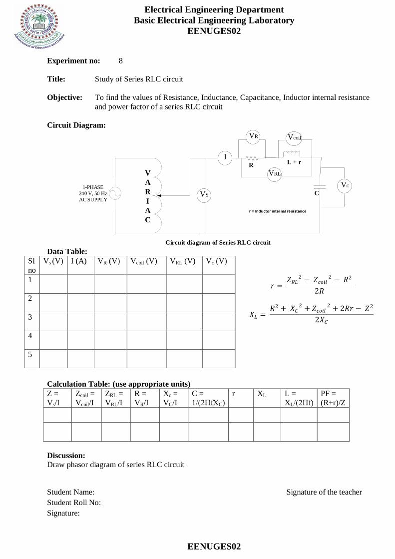
Experiment no: 8
Title: Study of Series RLC circuit
Objective: To find the values of Resistance, Inductance, Capacitance, Inductor internal resistance
and power factor of a series RLC circuit
Circuit Diagram:
1-PHASE
240 V, 50 Hz
AC SUPPLY
I
VS
V
A
R
I
A
C
VR Vcoil
VRL
VC
RL + r
C
Circuit diagram of Series RLC circuit
r = Inductor internal resistance
Data Table:
𝑟 = 𝑍𝑅𝐿
2 − 𝑍𝑐𝑜𝑖𝑙2 − 𝑅2
2𝑅
𝑋𝐿 = 𝑅2 + 𝑋𝐶
2 + 𝑍𝑐𝑜𝑖𝑙2 + 2𝑅𝑟 − 𝑍2
2𝑋𝐶
Calculation Table: (use appropriate units)
Z =
Vs/I
Zcoil =
Vcoil/I
ZRL =
VRL/I
R =
VR/I
Xc =
VC/I
C =
1/(2ΠfXC)
r XL L =
XL/(2Πf)
PF =
(R+r)/Z
Discussion:
Draw phasor diagram of series RLC circuit
Student Name: Signature of the teacher
Student Roll No:
Signature:
Sl
no
Vs (V) I (A) VR (V) Vcoil (V) VRL (V) Vc (V)
1
2
3
4
5
Electrical Engineering Department
Basic Electrical Engineering Laboratory
EENUGES02
EENUGES02
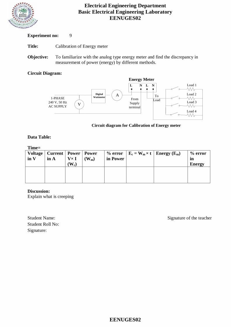
Experiment no: 9
Title: Calibration of Energy meter
Objective: To familiarize with the analog type energy meter and find the discrepancy in
measurement of power (energy) by different methods.
Circuit Diagram:
Circuit diagram for Calibration of Energy meter
V
A
Load 1
Load 2
Load 3
Load 4
Energy Meter
1-PHASE
240 V, 50 Hz
AC SUPPLY
Digital
Wattmeter
L N L N
From
Supply
terminal
To
Load
Data Table:
Time=
Voltage
in V
Current
in A
Power
V× I
(Wc)
Power
(Wm)
% error
in Power
Ec = Wm × t Energy (Em) % error
in
Energy
Discussion:
Explain what is creeping
Student Name: Signature of the teacher
Student Roll No:
Signature:
Electrical Engineering Department
Basic Electrical Engineering Laboratory
EENUGES02
EENUGES02
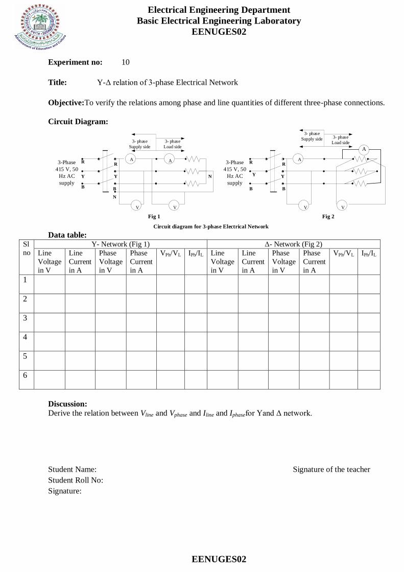
Experiment no: 10
Title: Y-Δ relation of 3-phase Electrical Network
Objective:To verify the relations among phase and line quantities of different three-phase connections.
Circuit Diagram:
3-Phase
415 V, 50
Hz AC
supply
A A
VV
3-Phase
415 V, 50
Hz AC
supply
A
A
VV
Fig 1 Fig 2
Circuit diagram for 3-phase Electrical Network
3- phase
Load side
3- phase
Supply side
3- phase
Load side
3- phase
Supply side
N
N
B
Y
RR
Y
B
R R
Y
B B
Y
Data table:
Sl no
Y- Network (Fig 1) Δ- Network (Fig 2)
Line
Voltage
in V
Line
Current
in A
Phase
Voltage
in V
Phase
Current
in A
VPh/VL IPh/IL Line
Voltage
in V
Line
Current
in A
Phase
Voltage
in V
Phase
Current
in A
VPh/VL IPh/IL
1
2
3
4
5
6
Discussion:
Derive the relation between Vline and Vphase and Iline and Iphasefor Yand Δ network.
Student Name: Signature of the teacher
Student Roll No:
Signature:
Electrical Engineering Department
Basic Electrical Engineering Laboratory
EENUGES02
EENUGES02
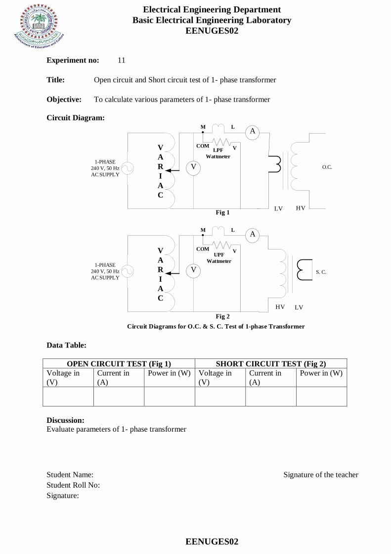
Experiment no: 11
Title: Open circuit and Short circuit test of 1- phase transformer
Objective: To calculate various parameters of 1- phase transformer
Circuit Diagram:
1-PHASE
240 V, 50 Hz
AC SUPPLY
V
A
R
I
A
C
M L
VCOM
A
V O.C.
HVLVFig 1
LPF
Wattmeter
1-PHASE
240 V, 50 Hz
AC SUPPLY
V
A
R
I
A
C
M L
VCOM
A
V
Fig 2
S. C.
HV LV
Circuit Diagrams for O.C. & S. C. Test of 1-phase Transformer
UPF
Wattmeter
Data Table:
OPEN CIRCUIT TEST (Fig 1) SHORT CIRCUIT TEST (Fig 2)
Voltage in
(V)
Current in
(A)
Power in (W) Voltage in
(V)
Current in
(A)
Power in (W)
Discussion:
Evaluate parameters of 1- phase transformer
Student Name: Signature of the teacher
Student Roll No:
Signature: