Embed Size (px)
Citation preview
Prince Sattam bin Abdulaziz University College of Engineering
Electrical Engineering Department EE 3360 Electrical Machines (II)
1 Dr. AHMED MOSTAFA HUSSEIN
Chapter # 4 Three-Phase Induction Machines
1- Introduction (General Principles)
Generally, conversion of electrical power into mechanical power takes place in the
rotating part of an electric motor. In DC motors, the electric power is conducted
directly to the armature (i.e. rotating part) through brushes and commutator. Hence,
in this sense, a DC motor is called a conduction motor. However, in AC motors, the
rotor receives its electric power by induction in exactly the same way as the
secondary of a 2-winding transformer receives its power from the primary. That is
why such motors are known as induction motors. In fact, an induction motor can be
treated as a rotating transformer i.e. one in which primary winding is stationary but
the secondary is free to rotate.
2- Construction
An induction motor consists essentially of two main parts: (a) stator and (b) rotor.
(a) Stator
The stator of an induction motor is the same as that of a synchronous motor or
generator. It is made up of a number of stampings, which are slotted to receive the
Prince Sattam bin Abdulaziz University College of Engineering
Electrical Engineering Department EE 3360 Electrical Machines (II)
2 Dr. AHMED MOSTAFA HUSSEIN
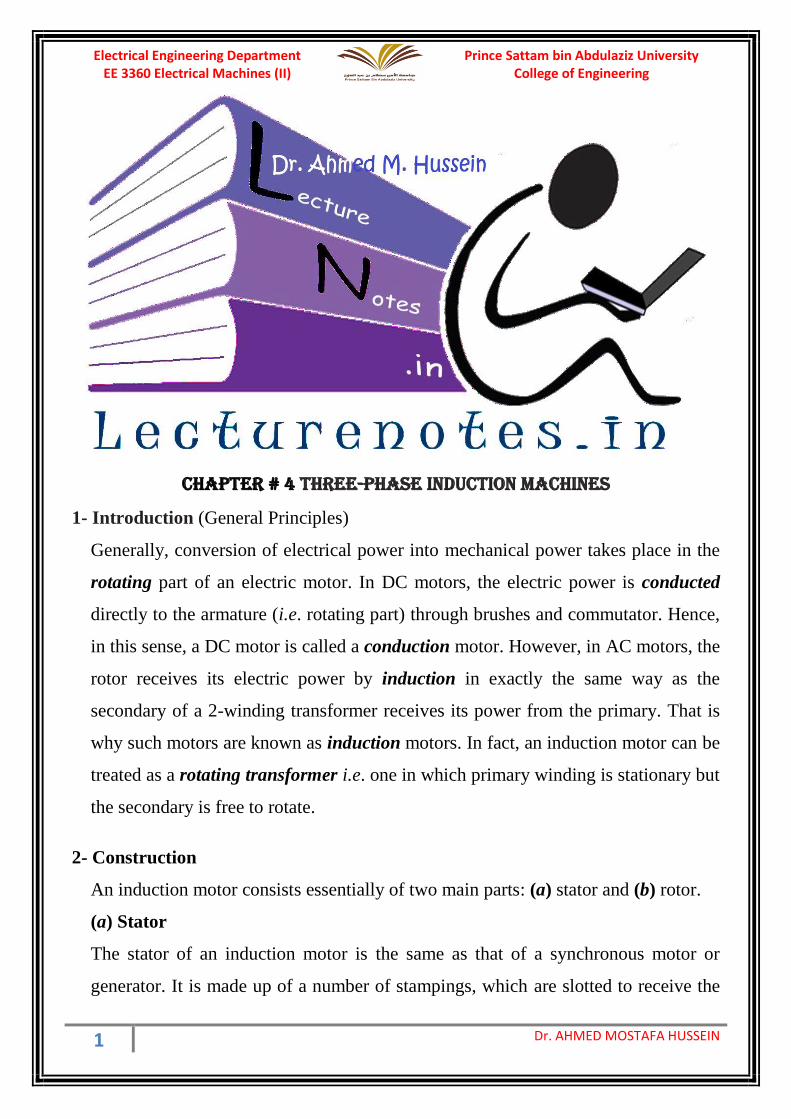
windings as shown in Fig. 1. The stator carries a 3-phase winding and is fed from a
3-phase supply. It is wound for a definite number of poles, the exact number of
poles being determined by the requirements of speed. Greater the number of poles,
lesser the speed and vice versa. As explained in chapter 1, that the stator windings,
when supplied with 3-phase currents, produce a magnetic flux, which is of constant
magnitude and revolves (rotates) at synchronous speed (Ns = 60 f/P). This revolving
magnetic flux induces an e.m.f. in the rotor by mutual induction.
Fig. 1, Stator of three-phase Induction Machines
(b) Rotor
There are two main types of rotor:
(i) Squirrel-cage rotor : Motors employing this type of rotor are known as squirrel-
cage induction motors. Almost 90 per cent of induction motors are squirrel-cage
type, because this type of rotor has the simplest and most rugged construction and
is almost indestructible. The rotor consists of a cylindrical laminated core with
parallel slots for carrying the rotor conductors which are not wires but consist of
heavy bars of copper, aluminium or alloys. One bar is placed in each slot, rather
Prince Sattam bin Abdulaziz University College of Engineering
Electrical Engineering Department EE 3360 Electrical Machines (II)
3 Dr. AHMED MOSTAFA HUSSEIN
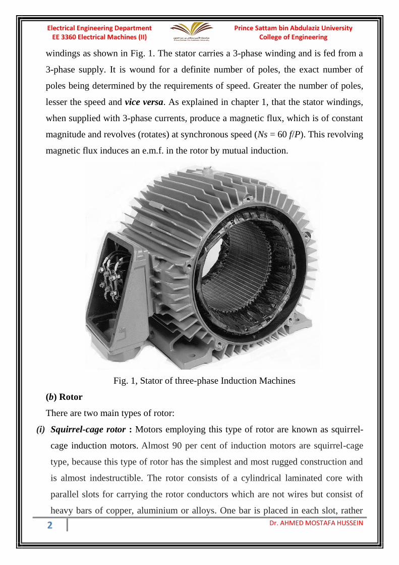
the bars are inserted from the end when semi-closed slots are used. The rotor bars
are brazed or electrically welded or bolted to two heavy and solid short-circuiting
end-rings, thus giving us, what is so called, a squirrel-cage construction (Fig. 2).
(a) (b) (c)
Fig. 2, Squirrel-cage Rotor
It should be noted that the rotor bars are permanently short-circuited on themselves,
hence it is not possible to add any external resistance in series with the rotor circuit for
starting purposes. The rotor slots are usually not quite parallel to the shaft but are
purposely given a slight skew (Fig. 2-a). This is useful in two ways :
• it helps to make the motor run quietly by reducing the magnetic hum and
• it helps in reducing the locking tendency of the rotor i.e. the tendency of the
rotor teeth to remain under the stator teeth due to direct magnetic attraction
between the stator and rotor.
In small motors, another method of construction of the squirrel-cage rotor is used. It
consists of placing the entire rotor core in a mould and casting all the bars and end-
rings in one piece. The metal commonly used is an aluminum alloy (Fig. 2-b).
Another form of rotor consists of a solid cylinder of steel without any conductors or
slots at all. The motor operation depends upon the production of eddy currents in the
steel rotor (Fig. 2-c).
(ii) Wound rotor: Motors employing this type of rotor are variously known as
‘wound’ motors or as ‘slip-ring’ motors as shown in Fig. 3.
Prince Sattam bin Abdulaziz University College of Engineering
Electrical Engineering Department EE 3360 Electrical Machines (II)
4 Dr. AHMED MOSTAFA HUSSEIN
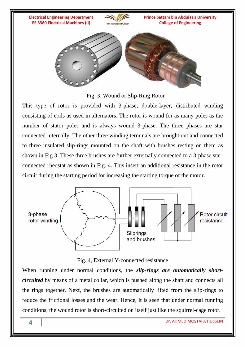
Fig. 3, Wound or Slip-Ring Rotor
This type of rotor is provided with 3-phase, double-layer, distributed winding
consisting of coils as used in alternators. The rotor is wound for as many poles as the
number of stator poles and is always wound 3-phase. The three phases are star
connected internally. The other three winding terminals are brought out and connected
to three insulated slip-rings mounted on the shaft with brushes resting on them as
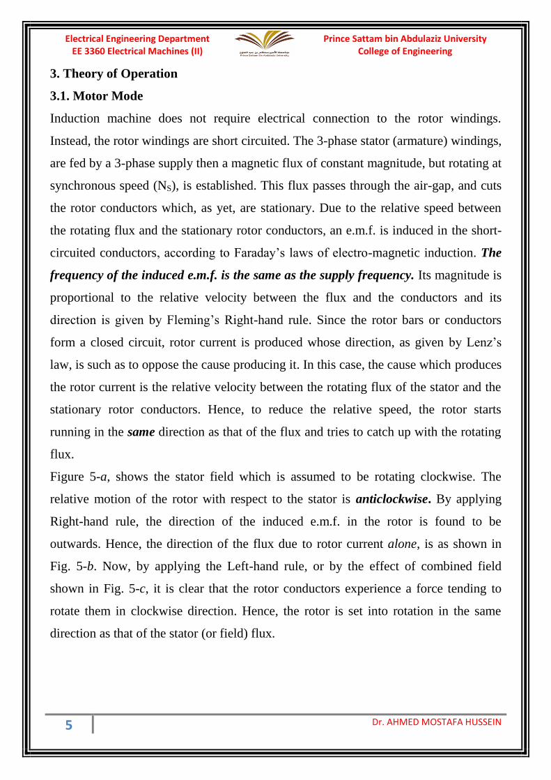
shown in Fig 3. These three brushes are further externally connected to a 3-phase star-
connected rheostat as shown in Fig. 4. This insert an additional resistance in the rotor
circuit during the starting period for increasing the starting torque of the motor.
Fig. 4, External Y-connected resistance
When running under normal conditions, the slip-rings are automatically short-
circuited by means of a metal collar, which is pushed along the shaft and connects all
the rings together. Next, the brushes are automatically lifted from the slip-rings to
reduce the frictional losses and the wear. Hence, it is seen that under normal running
conditions, the wound rotor is short-circuited on itself just like the squirrel-cage rotor.
Prince Sattam bin Abdulaziz University College of Engineering
Electrical Engineering Department EE 3360 Electrical Machines (II)
5 Dr. AHMED MOSTAFA HUSSEIN
3. Theory of Operation
3.1. Motor Mode
Induction machine does not require electrical connection to the rotor windings.
Instead, the rotor windings are short circuited. The 3-phase stator (armature) windings,
are fed by a 3-phase supply then a magnetic flux of constant magnitude, but rotating at
synchronous speed (NS), is established. This flux passes through the air-gap, and cuts
the rotor conductors which, as yet, are stationary. Due to the relative speed between
the rotating flux and the stationary rotor conductors, an e.m.f. is induced in the short-
circuited conductors, according to Faraday’s laws of electro-magnetic induction. The
frequency of the induced e.m.f. is the same as the supply frequency. Its magnitude is
proportional to the relative velocity between the flux and the conductors and its
direction is given by Fleming’s Right-hand rule. Since the rotor bars or conductors
form a closed circuit, rotor current is produced whose direction, as given by Lenz’s
law, is such as to oppose the cause producing it. In this case, the cause which produces
the rotor current is the relative velocity between the rotating flux of the stator and the
stationary rotor conductors. Hence, to reduce the relative speed, the rotor starts
running in the same direction as that of the flux and tries to catch up with the rotating
flux.
Figure 5-a, shows the stator field which is assumed to be rotating clockwise. The
relative motion of the rotor with respect to the stator is anticlockwise. By applying
Right-hand rule, the direction of the induced e.m.f. in the rotor is found to be
outwards. Hence, the direction of the flux due to rotor current alone, is as shown in
Fig. 5-b. Now, by applying the Left-hand rule, or by the effect of combined field
shown in Fig. 5-c, it is clear that the rotor conductors experience a force tending to
rotate them in clockwise direction. Hence, the rotor is set into rotation in the same
direction as that of the stator (or field) flux.

Prince Sattam bin Abdulaziz University College of Engineering
Electrical Engineering Department EE 3360 Electrical Machines (II)
6 Dr. AHMED MOSTAFA HUSSEIN
Fig. 5, Direction of rotor motion
3.2 Slip
In practice, in motor mode, the rotor never succeeds in ‘catching up’ with the stator
field. If it really did so, then there would be no relative speed between the two, hence
no rotor e.m.f., no rotor current and so no torque to maintain rotation. That is why the
rotor runs at a speed which is always less than the speed of the stator field. The
difference in speeds depends upon the load on the motor. The difference between the
synchronous speed Ns and the actual speed N of the rotor is known as the slip (S), that
can be expressed as a percentage of the synchronous speed as follows:
Sometimes, Ns − N is called the slip speed.
Obviously, rotor (or motor) speed is N = Ns (1 − s).
It may be kept in mind that revolving flux is rotating synchronously, relative to the
stator (i.e. stationary space) but at slip speed relative to the rotor.
3.3. Generator Mode
Induction machines are usually operated in motor mode. So they are usually called
induction motors. In normal motor operation, stator flux rotation is faster than the
rotor rotation. This causes the stator flux to induce rotor currents, which create a rotor
flux with magnetic polarity opposite to stator. In this way, the rotor is dragged along
behind stator flux, at a value equal to the slip.
Prince Sattam bin Abdulaziz University College of Engineering
Electrical Engineering Department EE 3360 Electrical Machines (II)
7 Dr. AHMED MOSTAFA HUSSEIN
On the other hand, in case of generator mode, a prime mover (turbine, engine) drives
the rotor above the synchronous speed. The stator flux still induces currents in the
rotor, but since the opposing rotor flux is now cutting the stator coils, an active current
is produced in stator coils, and the motor now operates as a generator, sending power
back to the electrical grid.
Therefore, the induction generators are not self-exciting. This means, they need an
initial electrical supply to produce the rotating magnetic flux. Practically, an induction
generator will often self start due to residual magnetism. The rotating magnetic flux
from the stator induces currents in the rotor, which also produces a magnetic field. If
the rotor turns slower than the rate of the rotating flux, the machine acts like an
induction motor. If the rotor is turned faster, it acts like a generator, producing power
at the synchronous frequency.
3.4 Frequency of Rotor Current
When the rotor is stationary, the frequency of rotor current is the same as the supply
frequency. But when the rotor starts revolving, then the frequency depends upon the
relative speed or on slip speed. Let the stator or supply frequency is f1 also let the
frequency of the rotor current at any slip-speed is f2 . Then
𝑠𝑙𝑖𝑝 𝑠𝑝𝑒𝑒𝑑 = 𝑁𝑠 − 𝑁 = 60 𝑓2
𝑃
𝑁𝑠 = 60 𝑓1
𝑃
Dividing the above two equations,
𝑁𝑠 − 𝑁
𝑁𝑠=
𝑓2
𝑓1= 𝑆
𝑟𝑜𝑡𝑜𝑟 𝑓𝑟𝑒𝑞𝑢𝑒𝑛𝑐𝑦 𝑓2 = 𝑆 𝑓1
When the rotor current flows through the individual phases of the rotor winding,
produces the rotor magnetic fields. These individual rotor magnetic fields produce a
combined rotating magnetic field, whose speed relative to rotor is
60 𝑓2
𝑃=
60 𝑆𝑓1
𝑃= 𝑆 𝑁𝑆
Prince Sattam bin Abdulaziz University College of Engineering
Electrical Engineering Department EE 3360 Electrical Machines (II)
8 Dr. AHMED MOSTAFA HUSSEIN
Example (1): A slip-ring induction motor runs at 290 r.p.m. at full load, when
connected to 50-Hz supply. Determine the number of poles and slip.
Since N is 290 rpm; Ns has to be somewhere near it, NS = 300 rpm.
Therefore 300 = 60 × f1/P =60×50/P. Hence, P = 10 and total number of poles is 2P =
20. ∴S = (300 − 290)/300 = 3.33%
Example (2): The stator of a 3-φ induction motor has 3 slots per pole per phase. If
supply frequency is 50 Hz, if the number of poles is double the coil groups; calculate:
(i) number of stator slots (ii) speed of the rotating stator flux (or magnetic field).
2P = 2Q = 2 × 3 = 6 poles
Total No. of slots = 3 slots/pole/phase × 6 poles × 3 phases = 54
(ii) Ns = 60 f/P = 60 × 50/3 = 1000 r.p.m.
Example (3): A 4-pole, 3-phase induction motor operates from a supply whose
frequency is 50 Hz. Calculate : (i) the speed at which the magnetic field of the stator is
rotating. (ii) the speed of the rotor when the slip is 0.04. (iii) the frequency of the rotor
currents when the slip is 0.03. (iv) The frequency of the rotor currents at standstill.
(i) Stator field revolves at synchronous speed, given by
Ns = 60 f1/P = 60 × 50/2 = 1500 r.p.m.
(ii) rotor (or motor) speed, N = Ns (1 − s) = 1500(1 − 0.04) = 1440 r.p.m.
(iii) frequency of rotor current, f 2 = sf1 = 0.03 × 50 = 1.5 c.p.s = 1.5 Hz
(iv) Since at standstill, s = 1, f 2 = sf1 = 1 × f1 = 50Hz
Example (4): A 3-φ induction motor is wound for 4 poles and is supplied from 50-Hz
system. Calculate (i) the synchronous speed (ii) the rotor speed, when slip is 4% and
(iii) rotor frequency when rotor runs at 600 rpm.
(i) Ns = 60 f1/P = 60 × 50/2 = 1500 rpm
(ii) rotor speed, N = Ns (1 − s) = 1500 (1 − 0.04) = 1440 rpm
(iii) when rotor speed is 600 rpm, slip is s = (Ns − N)/Ns = (1500 − 600)/1500 = 0.6
rotor current frequency, f2 = sf1 = 0.6 × 50 = 30 Hz
Prince Sattam bin Abdulaziz University College of Engineering
Electrical Engineering Department EE 3360 Electrical Machines (II)
9 Dr. AHMED MOSTAFA HUSSEIN
Example (5): A 12-pole, 3-phase alternator driven at a speed of 500 r.p.m. supplies
power to an 8-pole, 3-phase induction motor. If the slip of the motor, at full-load is
3%, calculate the full-load speed of the motor.
Let N = actual motor speed; Supply frequency, f1 = 6 × 500/60 = 50 Hz.
Synchronous speed Ns = 60 × 50/4 = 750 r.p.m.
Slip s = 0.03 = (Ns – N)/Ns = (750 – N)/750
Rotor speed N = 750 – 0.03 × 750 = 727.5 r.p.m.
4. Equivalent Circuit per phase for Induction Motor
we can derive the equivalent circuit for one phase of the 3-phase induction machine,
with the understanding that the voltages and currents in the remaining phases can be
found simply by an appropriate phase shift of those of the phase under study (±120°).
First, consider conditions of operation of induction motor whose stator is supplied by a
terminal voltage V1. The stator terminal voltage differs from the generated back emf
(E1) by the voltage drop in the stator leakage impedance Z1 = R1 + j X1.
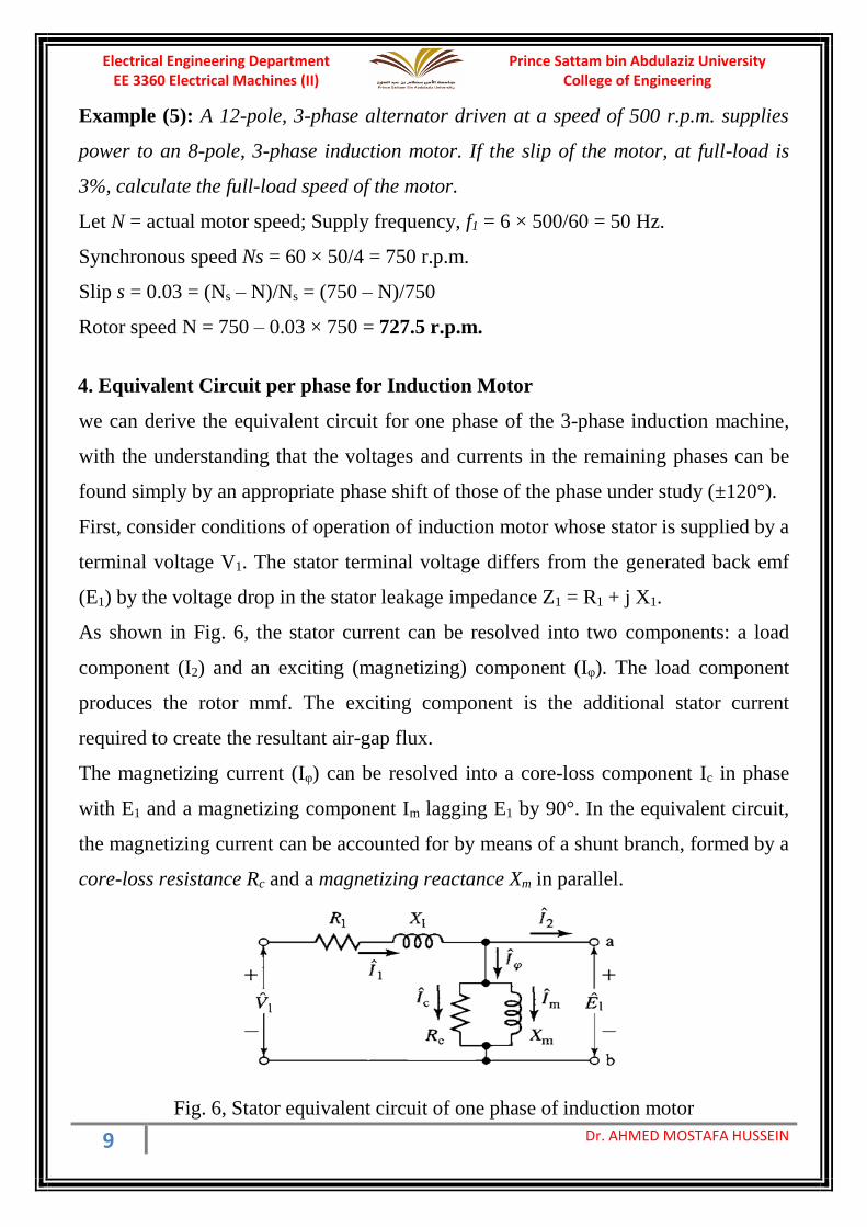
As shown in Fig. 6, the stator current can be resolved into two components: a load
component (I2) and an exciting (magnetizing) component (Iφ). The load component
produces the rotor mmf. The exciting component is the additional stator current
required to create the resultant air-gap flux.
The magnetizing current (Iφ) can be resolved into a core-loss component Ic in phase
with E1 and a magnetizing component Im lagging E1 by 90°. In the equivalent circuit,
the magnetizing current can be accounted for by means of a shunt branch, formed by a
core-loss resistance Rc and a magnetizing reactance Xm in parallel.
Fig. 6, Stator equivalent circuit of one phase of induction motor
Prince Sattam bin Abdulaziz University College of Engineering
Electrical Engineering Department EE 3360 Electrical Machines (II)
10 Dr. AHMED MOSTAFA HUSSEIN
Where
V1 Stator line-to-neutral terminal voltage
E1 Back emf (line-to-neutral) generated by the resultant air-gap flux
Il Stator current
R1 Stator effective resistance
X1 Stator leakage reactance
Rc Core loss resistance
Xm magnetizing branch reactance
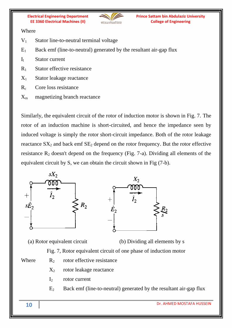
Similarly, the equivalent circuit of the rotor of induction motor is shown in Fig. 7. The
rotor of an induction machine is short-circuited, and hence the impedance seen by
induced voltage is simply the rotor short-circuit impedance. Both of the rotor leakage
reactance SX2 and back emf SE2 depend on the rotor frequency. But the rotor effective
resistance R2 doesn't depend on the frequency (Fig. 7-a). Dividing all elements of the
equivalent circuit by S, we can obtain the circuit shown in Fig (7-b).
(a) Rotor equivalent circuit (b) Dividing all elements by s
Fig. 7, Rotor equivalent circuit of one phase of induction motor
Where R2 rotor effective resistance
X2 rotor leakage reactance
I2 rotor current
E2 Back emf (line-to-neutral) generated by the resultant air-gap flux
Prince Sattam bin Abdulaziz University College of Engineering
Electrical Engineering Department EE 3360 Electrical Machines (II)
11 Dr. AHMED MOSTAFA HUSSEIN
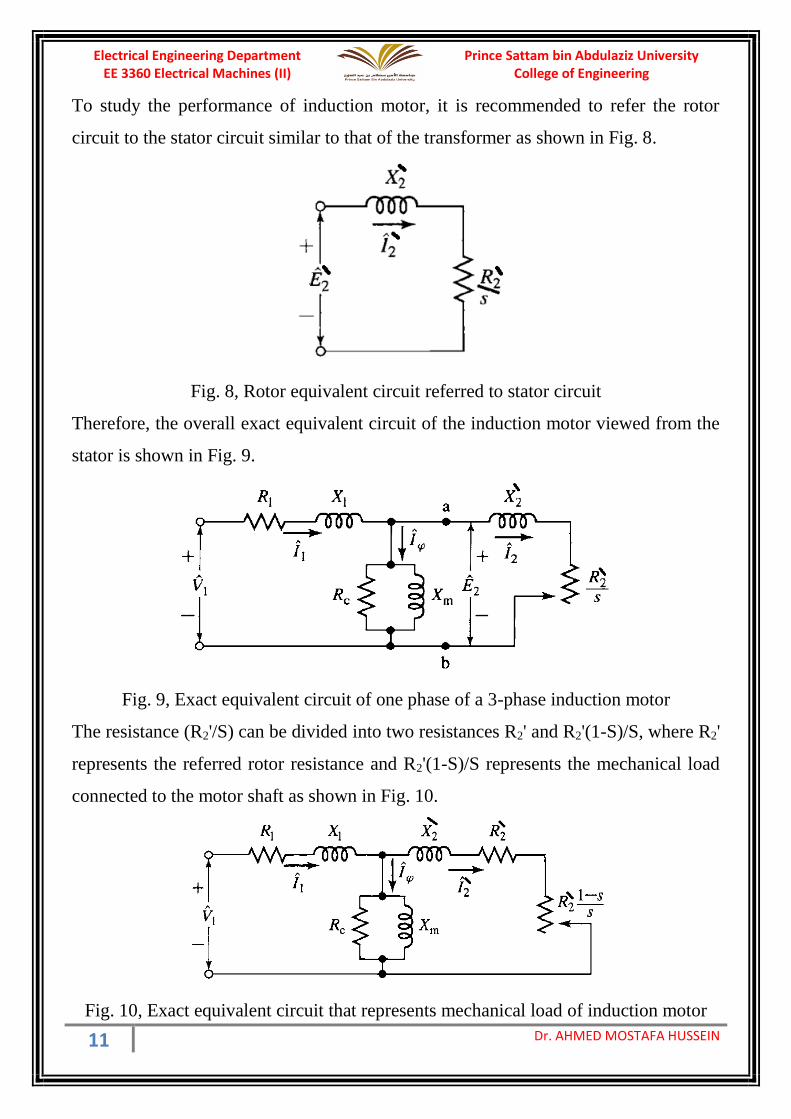
To study the performance of induction motor, it is recommended to refer the rotor
circuit to the stator circuit similar to that of the transformer as shown in Fig. 8.
Fig. 8, Rotor equivalent circuit referred to stator circuit
Therefore, the overall exact equivalent circuit of the induction motor viewed from the
stator is shown in Fig. 9.
Fig. 9, Exact equivalent circuit of one phase of a 3-phase induction motor
The resistance (R2'/S) can be divided into two resistances R2' and R2'(1-S)/S, where R2'
represents the referred rotor resistance and R2'(1-S)/S represents the mechanical load
connected to the motor shaft as shown in Fig. 10.
Fig. 10, Exact equivalent circuit that represents mechanical load of induction motor
Prince Sattam bin Abdulaziz University College of Engineering
Electrical Engineering Department EE 3360 Electrical Machines (II)
12 Dr. AHMED MOSTAFA HUSSEIN
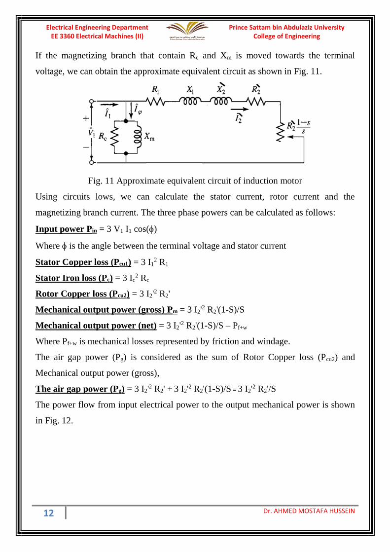
If the magnetizing branch that contain Rc and Xm is moved towards the terminal
voltage, we can obtain the approximate equivalent circuit as shown in Fig. 11.
Fig. 11 Approximate equivalent circuit of induction motor
Using circuits lows, we can calculate the stator current, rotor current and the
magnetizing branch current. The three phase powers can be calculated as follows:
Input power Pin = 3 V1 I1 cos()
Where is the angle between the terminal voltage and stator current
Stator Copper loss (Pcu1) = 3 I12 R1
Stator Iron loss (Pc) = 3 Ic2 Rc
Rotor Copper loss (Pcu2) = 3 I2'2 R2'
Mechanical output power (gross) Pm = 3 I2'2 R2'(1-S)/S
Mechanical output power (net) = 3 I2'2 R2'(1-S)/S – Pf+w
Where Pf+w is mechanical losses represented by friction and windage.
The air gap power (Pg) is considered as the sum of Rotor Copper loss (Pcu2) and
Mechanical output power (gross),
The air gap power (Pg) = 3 I2'2 R2' + 3 I2'
2 R2'(1-S)/S = 3 I2'2 R2'/S
The power flow from input electrical power to the output mechanical power is shown
in Fig. 12.
Prince Sattam bin Abdulaziz University College of Engineering
Electrical Engineering Department EE 3360 Electrical Machines (II)
13 Dr. AHMED MOSTAFA HUSSEIN
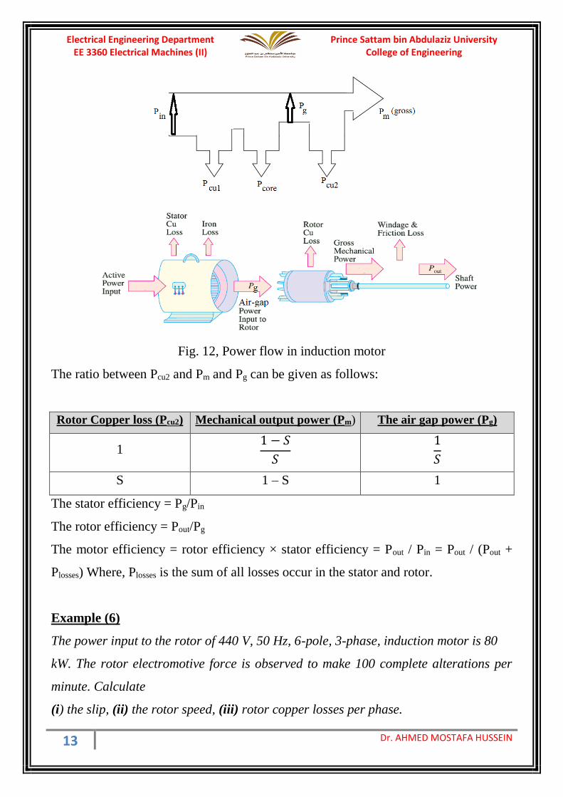
Fig. 12, Power flow in induction motor
The ratio between Pcu2 and Pm and Pg can be given as follows:
Rotor Copper loss (Pcu2) Mechanical output power (Pm) The air gap power (Pg)
1 1 − 𝑆
𝑆
1
𝑆
S 1 – S 1
The stator efficiency = Pg/Pin
The rotor efficiency = Pout/Pg
The motor efficiency = rotor efficiency × stator efficiency = Pout / Pin = Pout / (Pout +
Plosses) Where, Plosses is the sum of all losses occur in the stator and rotor.
Example (6)
The power input to the rotor of 440 V, 50 Hz, 6-pole, 3-phase, induction motor is 80
kW. The rotor electromotive force is observed to make 100 complete alterations per
minute. Calculate
(i) the slip, (ii) the rotor speed, (iii) rotor copper losses per phase.
Prince Sattam bin Abdulaziz University College of Engineering
Electrical Engineering Department EE 3360 Electrical Machines (II)
14 Dr. AHMED MOSTAFA HUSSEIN
Solution:
Rotor alternation per minutes = 100
Rotor alternation per second (f2) = 100/60 = 1.6667 = Sf1
S = 1.6667/50 = 0.03333 = 3.33%
Ns = 60 × 50 / 3 = 1000 rpm
N = Ns(1-s) = 1000 (1-0.0333) = 966.67 rpm
The rotor input power is the air gap power = 80 kW
The rotor copper loss Pcu2 = S Pg = 0.0333 × 80000 = 2.667 kW (for the 3 phase)
= 2667/3 = 888.8 W
Example (7)
A three-phase, Y-connected, 220-V (line-to-line), 7.5-kW, 60-Hz, 6-pole induction
motor has the following parameter values in Ω/phase referred to the stator:
R1 = 0.294Ω R2' = 0.144 Ω Rc = 415 Ω
X1 = 0.503 Ω X2' = 0.209 Ω Xm = 13.25 Ω
The total friction and windage losses may be assumed to be constant at 403 W,
independent of load. For a slip of 2 %, and based on approximate equivalent circuit,
compute the rotor speed, output torque and power, stator current, power factor, iron
loss, electromagnetic torque and efficiency when the motor is operated at rated voltage
and frequency.
Solution
Refer to the approximate equivalent circuit shown in Fig. 11,
S = 0.02 Ns = 60×f / P = 60×60 / 3 = 1200 rpm
** The rotor speed (N) = Ns (1-S) = 1200 (1-0.02) = 1176 rpm #
𝑅2′
𝑆=
0.144
0.02= 7.2 Ω
Z = (R1 + R2'/S) + J(X1+X2') = 7.494+J0.712 = 7.5277∟5.4273 Ω
𝐼2′ =
𝑉1
𝑍=
220/√3
7.5277∠5.4273= 16.8732∠ − 5.4273 𝐴
Zm = Rc // JXm = (Rc × JXm) / (Rc + JXm) = 13.2433∟88.1713 Ω
Prince Sattam bin Abdulaziz University College of Engineering
Electrical Engineering Department EE 3360 Electrical Machines (II)
15 Dr. AHMED MOSTAFA HUSSEIN
𝐼𝜙 = 𝑉1
𝑍𝑚=
220/√3
13.2433∠88.1713= 9.5911∠ − 88.1713 𝐴
** The stator current can be obtained as: I1 = I2' + I = 20.4346∟-33.1761 A
** The input P.F. is considered as cosine the angle between the input voltage and
stator current i.e. cos(33.1761) = 0.837 lag.
The output mech. Power (Gross) = 3 I2'2 R2'(1-S)/S = 3×(16.8732)2×0.144(1-
0.02)/0.02
= 6026.633 W
** The output mech. Power (Net) = The output mech. Power (Gross) – Pf+w
= 6026.633 – 403 = 5623.633 W
ω = 2π N/60 = 2π × 1176 / 60 = 123.1504 rad/s
** the developed (output) torque (T) = The output mech. Power (Net)/ω
= 5623.633 / 123.1504 = 45.6647 N.m
** Air-gap power (Pg) = 3 I2'2 R2'/S = 3×(16.8732)2×0.144/0.02 = 6149.6254 W
ωS = 2π NS/60 = 2π × 1200 / 60 = 125.6637 rad/s
** electromagnetic torque (Tem) = Air-gap power (Pg) / ωS
= 6149.6254 / 125.6637 = 48.9372 N.m
Iron loss (Piron) = 3× V12 / Rc = 3×(220/3)2/415 = 116.6265 W
Input power (Pin) = 3 V1 I1 cos() = 3× (220/3) × 20.4346 × 0.837 = 6517.408 W
Efficiency = Pout / Pin = 5623.633 / 6517.408 = 86.286 %
Example (8):
A 100-kW (net output), 3300-V, 50-Hz, 3-phase, star-connected induction motor has a
synchronous speed of 500 r.p.m. The full-load slip is 1.8% and full-load power factor
is 0.85 lag. If the stator copper loss is 2440 W, the iron loss is 3500 W, and the friction
and windage loss is 1200 W.
Calculate (i) Rotor copper loss and the gross mechanical power
(ii) Rotor efficiency, stator efficiency, and motor efficiency
(iii) Input line current
Pmech(Gross) = 100000+1200 = 101200 W
Prince Sattam bin Abdulaziz University College of Engineering
Electrical Engineering Department EE 3360 Electrical Machines (II)
16 Dr. AHMED MOSTAFA HUSSEIN
𝑃𝑔 =𝑃𝑚𝑒𝑐ℎ(𝐺𝑟𝑜𝑠𝑠)
1 − 𝑆=
101200
1 − 0.018= 103055 𝑊
Pcu2 = Pg – Pmech (Gross) = 103055 – 101200 = 1855 W
Pin = Pg + Piron + Pcu1 = 103055+3500+2440=108995 W
𝑟𝑜𝑡𝑜𝑟 𝑒𝑓𝑓𝑖𝑐𝑖𝑒𝑛𝑐𝑦 =𝑃𝑜𝑢𝑡(𝑛𝑒𝑡)
𝑃𝑔=
100000
103055×100% = 97.0356%
𝑠𝑡𝑎𝑡𝑜𝑟 𝑒𝑓𝑓𝑖𝑐𝑖𝑒𝑛𝑐𝑦 =𝑃𝑔
𝑃𝑖𝑛=
103055
108995×100% = 94.55%
𝑚𝑜𝑡𝑜𝑟 𝑒𝑓𝑓𝑖𝑐𝑖𝑒𝑛𝑐𝑦 =𝑃𝑜𝑢𝑡(𝑛𝑒𝑡)
𝑃𝑖𝑛=
100000
108995×100% = 91.747%
𝐼𝑎 =108995
√3×3300×0.85= 22.434 𝐴
Example (9)
A 400 V, 3-phase, 50 Hz, 4-pole, star-connected induction-motor takes a line current
of 10 A with 0.86 p. f. lagging. If the total stator losses are 5 % of the its input. Rotor
copper losses are 4 % of the rotor input, and mechanical losses are 3 % of the input of
the rotor. Calculate (i) slip and rotor speed, (ii) torque developed in the rotor, and
(iii) shaft-torque. (iv) motor efficiency
Input to motor (Pin) = √3 × 400 × 10 × 0.86 = 5958 Watts
Total stator losses (Pcu1 + Piron) = 0.05 × 5958 = 298 Watts
Stator Output = 5958 − 298 = 5660 Watts
Rotor input (Pg) = Stator Output = 5660 Watts
Rotor Copper-loss (Pcu2) = 0.04 × 5660 = 226.4 Watts
Mechanical losses (Pf+w) = 0.03 × 5660 = 169.8 Watts
Mechanical output (Net) = 5660 − (226.4 + 169.8) = 5264 Watts
(i) slip, s = Rotor-copper-loss / rotor-input = 4 %
Synchronous speed, Ns = 60 × f/P =1500 rpm
Prince Sattam bin Abdulaziz University College of Engineering
Electrical Engineering Department EE 3360 Electrical Machines (II)
17 Dr. AHMED MOSTAFA HUSSEIN
Rotor speed, N = Ns (1 − s) = 1500 (1 − 0.04) = 1440 rpm
(ii) Let the torque developed in the rotor = Td
ωr Angular speed of rotor = 2π N/60 = 150.72 rad/sec
ωs Angular speed of flux = 2π Ns/60 = 157 rad/sec
Mechanical output (Gross) = Rotor input − Rotor-copper-loss
= 5660 − 226.4 = 5433.6 watts
the developed torque can be obtained either by:
Td = 5433.6 / 150.72 = 36.05 Nw-m
Td = 5660 / 157 = 36.05 Nw-m
(iii) Shaft-torque = Tm = Pm (Net) /ωr
= 5264 / 150.72 = 34.93 Nw-m.
(iv) motor Efficiency = Pm(net)/Pin = 5264/5958 = 88.35%
5. Torque-Speed Characteristics
If there is no rotational loss and the rotor copper loss is also ignored, the developed
torque and the electromagnetic torque are equal. There are two ways to calculate that
torque
𝑇(𝑑𝑒𝑣𝑒𝑙𝑜𝑝𝑒𝑑) = 𝑀𝑒𝑐ℎ. 𝑝𝑜𝑤𝑒𝑟 (𝑔𝑟𝑜𝑠𝑠)
𝜔=
3 𝐼2′ 2
𝑅2′ (1 − 𝑆)/𝑆
𝜔
𝑇(𝑒𝑙𝑒𝑐𝑡𝑟𝑜𝑚𝑎𝑔𝑛𝑒𝑡𝑖𝑐) = 𝐴𝑖𝑟 − 𝑔𝑎𝑝 𝑝𝑜𝑤𝑒𝑟
𝜔𝑆=
3 𝐼2′ 2
𝑅2′ /𝑆
𝜔/(1 − 𝑠)=
3 𝐼2′ 2
𝑅2′ (1 − 𝑆)/𝑆
𝜔
Considering the approximate equivalent circuit,
𝐼2′ =
𝑉1
√(𝑅1 +𝑅2
′
𝑆 )2
+ (𝑋1 + 𝑋2′ )2
𝑇 = 3 𝑉1
2 𝑅2
′
𝑆
𝜔𝑆 (𝑅1 +𝑅2
′
𝑆 )2
+ (𝑋1 + 𝑋2′ )2
Prince Sattam bin Abdulaziz University College of Engineering
Electrical Engineering Department EE 3360 Electrical Machines (II)
18 Dr. AHMED MOSTAFA HUSSEIN
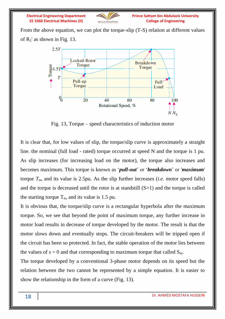
From the above equation, we can plot the torque-slip (T-S) relation at different values
of R2' as shown in Fig. 13.
Fig. 13, Torque – speed characteristics of induction motor
It is clear that, for low values of slip, the torque/slip curve is approximately a straight
line. the nominal (full load - rated) torque occurred at speed N and the torque is 1 pu.
As slip increases (for increasing load on the motor), the torque also increases and
becomes maximum. This torque is known as ‘pull-out’ or ‘breakdown’ or 'maximum'
torque Tm, and its value is 2.5pu. As the slip further increases (i.e. motor speed falls)
and the torque is decreased until the rotor is at standstill (S=1) and the torque is called
the starting torque Tst, and its value is 1.5 pu.
It is obvious that, the torque/slip curve is a rectangular hyperbola after the maximum
torque. So, we see that beyond the point of maximum torque, any further increase in
motor load results in decrease of torque developed by the motor. The result is that the
motor slows down and eventually stops. The circuit-breakers will be tripped open if
the circuit has been so protected. In fact, the stable operation of the motor lies between
the values of s = 0 and that corresponding to maximum torque that called Sm.
The torque developed by a conventional 3-phase motor depends on its speed but the
relation between the two cannot be represented by a simple equation. It is easier to
show the relationship in the form of a curve (Fig. 13).
Prince Sattam bin Abdulaziz University College of Engineering
Electrical Engineering Department EE 3360 Electrical Machines (II)
19 Dr. AHMED MOSTAFA HUSSEIN
6. Maximum Torque
As we said before, T=Pg/ωS. Since the synchronous speed is constant, the maximum
torque (Tm) occurs at the same slip as maximum air-gap power. This slip is called (Sm)
and can be obtained as:
𝑆𝑚 = 𝑅2
′
√(𝑅1)2 + (𝑋1 + 𝑋2′ )2
To obtain the expression for the maximum torque (Tm), substituting the value of Sm in
the torque equation,
𝑇𝑚 = 3 𝑉1
2 √𝑅12 + (𝑋1 + 𝑋2
′ )2
𝜔𝑆 (𝑅1 + √𝑅12 + (𝑋1 + 𝑋2
′ )2)2
+ (𝑋1 + 𝑋2′ )2
𝑇𝑚 = 3 𝑉1
2
2𝜔𝑆 𝑅1 + √𝑅12 + (𝑋1 + 𝑋2
′ )2
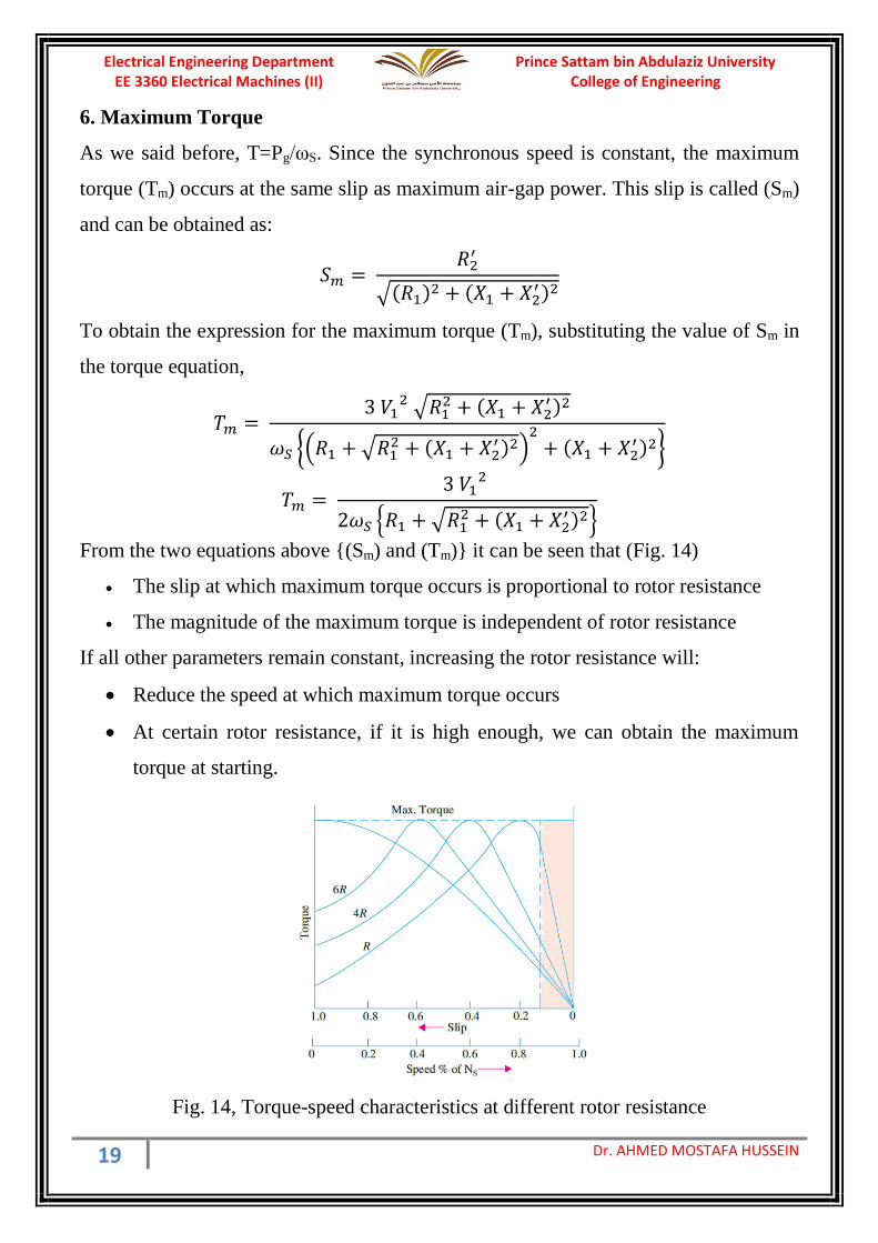
From the two equations above (Sm) and (Tm) it can be seen that (Fig. 14)
• The slip at which maximum torque occurs is proportional to rotor resistance
• The magnitude of the maximum torque is independent of rotor resistance
If all other parameters remain constant, increasing the rotor resistance will:
• Reduce the speed at which maximum torque occurs
• At certain rotor resistance, if it is high enough, we can obtain the maximum
torque at starting.
Fig. 14, Torque-speed characteristics at different rotor resistance
Prince Sattam bin Abdulaziz University College of Engineering
Electrical Engineering Department EE 3360 Electrical Machines (II)
20 Dr. AHMED MOSTAFA HUSSEIN
Example (10)
A 440-V, 3-φ, 50-Hz, 4-pole, Y-connected induction motor has a full-load speed of
1425 rpm. The rotor has an impedance of (0.4 + J 4) Ω and rotor/stator turns ratio of
0.8. Based on approximate equivalent circuit referred to stator, calculate
(i) full-load torque
(ii) rotor current and full-load rotor Cu loss
(iii ) power output if windage and friction losses amount to 500 W
(iv) maximum torque and the speed at which it occurs
(v) starting current and
(vi) starting torque.
Solution
Ns = 60 × 50/2 = 1500 rpm and ωS = 2π×1500/60 = 157.08 rad/s
S = (1500 – 1425) / 1500 = 0.05 (full-load slip)
R2' = 0.4/(0.8)2 = 0.625 Ω
X2' = 4.0/(0.8)2 = 6.25 Ω
Rotor impedance Z2' = R2'/S + J X2' = 12.5 + J6.25 = 13.9754∟26.5651 Ω
Rotor current I2' = (440/3)/13.9754 = 18.177 A (full-load current)
T = 3 (I2')2 (R2'/S)/ωs = 3×(18.177)2×12.5/157.08 = 78.878 N.m (full-load torque)
Air-gap power (Pg) = T×ωS = 78.878×157.08 = 12.390 kW
Rotor copper loss (Pcu2) = S×Pg = 0.05×12390 = 619.51 W
Mechanical power (Gross) = Pg(1-S) = 12390 (1-0.05) = 11.77 kW
Mechanical power (Net) = 11770 – 500 = 11.27 kW
If the stator impedance is neglected
𝑆𝑚 = 𝑅2
′
𝑋2′ =
0.625
6.25= 0.1
Rotor speed (N) at maximum torque = 1500×(1-0.1) = 1350 rpm
At maximum torque,
Rotor impedance Z2' = R2'/S + J X2' = 6.25 + J6.25 =8.839∟45

Prince Sattam bin Abdulaziz University College of Engineering
Electrical Engineering Department EE 3360 Electrical Machines (II)
21 Dr. AHMED MOSTAFA HUSSEIN
Rotor Current I2' = (440/3)/8.839 = 28.74 A (Rotor current at Tm)
Tm = 3 (I2')2 (R2'/S)/ωs = 3×(28.74)2×6.25/157.08 = 98.6 N.m
At starting, (S=1)
Rotor impedance Z2' = R2'/S + J X2' = 0.625 + J6.25 =6.2812∟84.29 Ω
Rotor Current I2' = (440/3)/6.2812 = 40.444 A (Rotor current at starting)
Tst = 3 (I2')2 (R2'/S)/ωs = 3×(40.444)2×0.625/157.08 = 19.525 N.m
7. Relation Between Torques
As we know that, the torque = 3 (I2')2 (R2'/S)/ωs, therefore,
𝑇𝑓.𝑙 = 3× 𝐼2𝑓𝑙′ 2
×𝑅2
′
𝑆𝑓𝑙/𝜔𝑠
𝑇𝑠𝑡 = 3× 𝐼2𝑠𝑡′ 2
×𝑅2
′
1/𝜔𝑠
𝑇𝑚 = 3× 𝐼2𝑚′ 2
×𝑅2
′
𝑆𝑚/𝜔𝑠
From the above equations, we can obtain the following torque relation:
𝑇𝑚
𝑇𝑓.𝑙= (
𝐼2𝑚′
𝐼2𝑓𝑙′ )
2𝑆𝑓𝑙
𝑆𝑚
𝑇𝑠𝑡
𝑇𝑓.𝑙= (
𝐼2𝑠𝑡′
𝐼2𝑓𝑙′ )
2
𝑆𝑓𝑙
By knowing the slips, we can find another set of relations
𝑇𝑓𝑙
𝑇𝑚=
2 𝑆𝑓𝑙 𝑆𝑚
𝑆𝑓𝑙2 + 𝑆𝑚
2
𝑇𝑠𝑡
𝑇𝑚=
2 𝑆𝑚
1 + 𝑆𝑚2
Example (11)
For a 3-phase induction motor having a full-load slip of 3%, the stator impedance and
the referred rotor impedance are identical. Also, in each impedance, the leakage
reactance is five times the resistance. Determine the P.U. value of the starting torque
and maximum torque.
Sf.l = 0.03 Also Z1 = Z2' This means R1 + jX1 = R2' + JX2'
Prince Sattam bin Abdulaziz University College of Engineering
Electrical Engineering Department EE 3360 Electrical Machines (II)
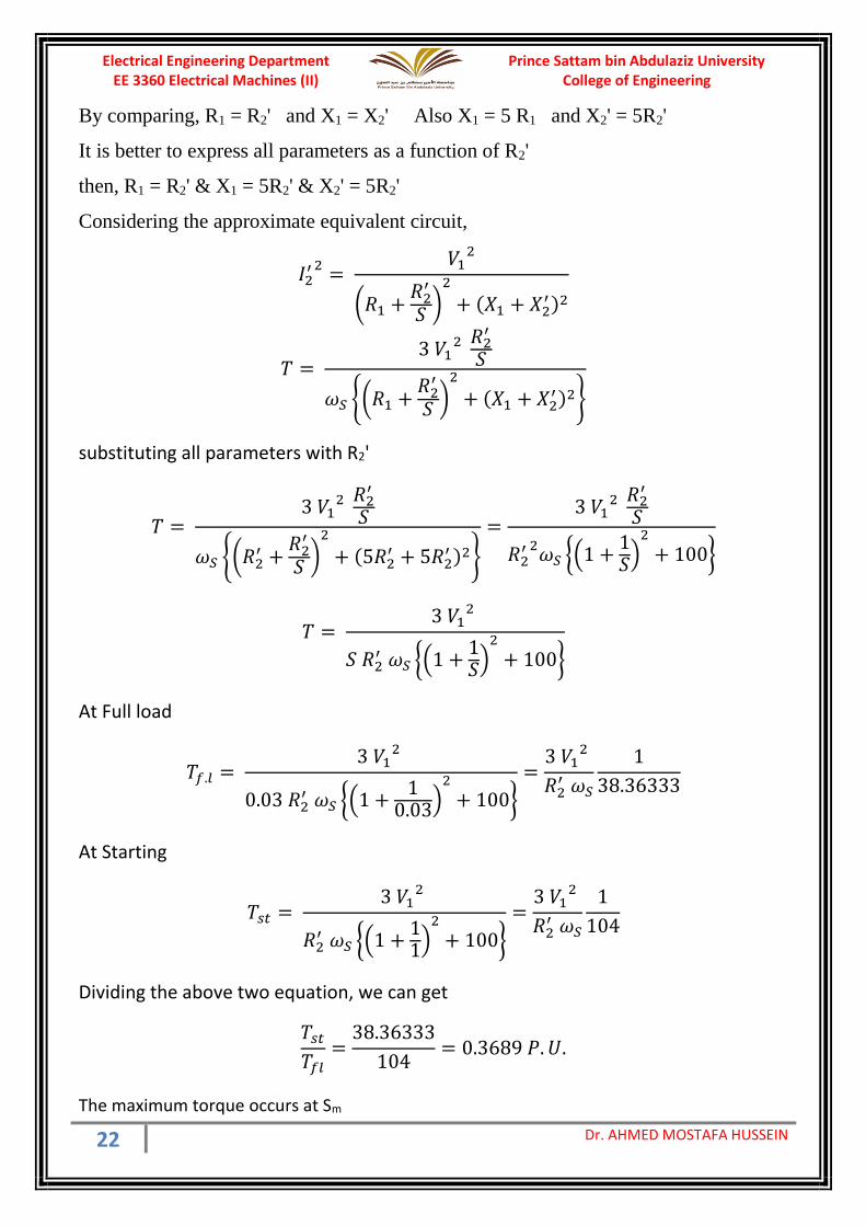
22 Dr. AHMED MOSTAFA HUSSEIN
By comparing, R1 = R2' and X1 = X2' Also X1 = 5 R1 and X2' = 5R2'
It is better to express all parameters as a function of R2'
then, R1 = R2' & X1 = 5R2' & X2' = 5R2'
Considering the approximate equivalent circuit,
𝐼2′ 2
= 𝑉1
2
(𝑅1 +𝑅2
′
𝑆 )2
+ (𝑋1 + 𝑋2′ )2
𝑇 = 3 𝑉1
2 𝑅2
′
𝑆
𝜔𝑆 (𝑅1 +𝑅2
′
𝑆 )2
+ (𝑋1 + 𝑋2′ )2
substituting all parameters with R2'
𝑇 = 3 𝑉1
2 𝑅2
′
𝑆
𝜔𝑆 (𝑅2′ +
𝑅2′
𝑆 )2
+ (5𝑅2′ + 5𝑅2
′ )2
=3 𝑉1
2 𝑅2
′
𝑆
𝑅2′ 2
𝜔𝑆 (1 +1𝑆)
2
+ 100
𝑇 = 3 𝑉1
2
𝑆 𝑅2′ 𝜔𝑆 (1 +
1𝑆)
2
+ 100
At Full load
𝑇𝑓.𝑙 = 3 𝑉1
2
0.03 𝑅2′ 𝜔𝑆 (1 +
10.03)
2
+ 100
=3 𝑉1
2
𝑅2′ 𝜔𝑆
1
38.36333
At Starting
𝑇𝑠𝑡 = 3 𝑉1
2
𝑅2′ 𝜔𝑆 (1 +
11)
2
+ 100
=3 𝑉1
2
𝑅2′ 𝜔𝑆
1
104
Dividing the above two equation, we can get
𝑇𝑠𝑡
𝑇𝑓𝑙=
38.36333
104= 0.3689 𝑃. 𝑈.
The maximum torque occurs at Sm
Prince Sattam bin Abdulaziz University College of Engineering
Electrical Engineering Department EE 3360 Electrical Machines (II)
23 Dr. AHMED MOSTAFA HUSSEIN
𝑆𝑚 = 𝑅2
′
√(𝑅1)2 + (𝑋1 + 𝑋2′ )2
=𝑅2
′
√(𝑅2′ )2 + (5𝑅2
′ + 5𝑅2′ )2
=1
√101= 0.0995
𝑇𝑚𝑎𝑥 = 3 𝑉1
2
0.0995 𝑅2′ 𝜔𝑆 (1 +
10.0995)
2
+ 100
=3 𝑉1
2
𝑅2′ 𝜔𝑆
1
22.1
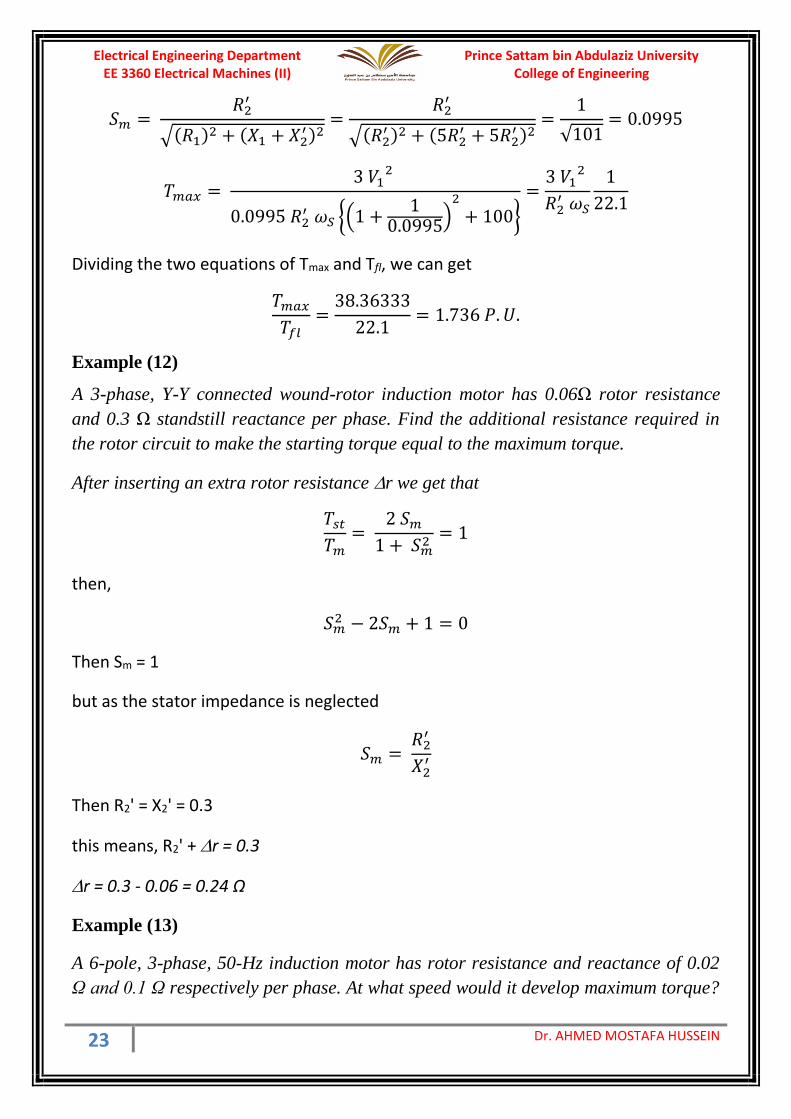
Dividing the two equations of Tmax and Tfl, we can get
𝑇𝑚𝑎𝑥
𝑇𝑓𝑙=
38.36333
22.1= 1.736 𝑃. 𝑈.
Example (12)
A 3-phase, Y-Y connected wound-rotor induction motor has 0.06Ω rotor resistance
and 0.3 Ω standstill reactance per phase. Find the additional resistance required in
the rotor circuit to make the starting torque equal to the maximum torque.
After inserting an extra rotor resistance r we get that
𝑇𝑠𝑡
𝑇𝑚=
2 𝑆𝑚
1 + 𝑆𝑚2
= 1
then,
𝑆𝑚2 − 2𝑆𝑚 + 1 = 0
Then Sm = 1
but as the stator impedance is neglected
𝑆𝑚 = 𝑅2
′
𝑋2′
Then R2' = X2' = 0.3
this means, R2' + r = 0.3
r = 0.3 - 0.06 = 0.24 Ω
Example (13)
A 6-pole, 3-phase, 50-Hz induction motor has rotor resistance and reactance of 0.02
Ω and 0.1 Ω respectively per phase. At what speed would it develop maximum torque?
Prince Sattam bin Abdulaziz University College of Engineering
Electrical Engineering Department EE 3360 Electrical Machines (II)
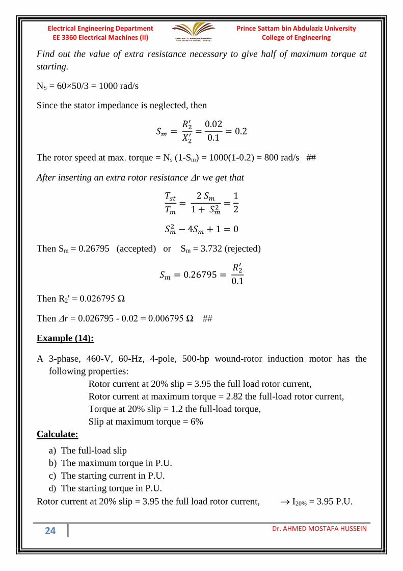
24 Dr. AHMED MOSTAFA HUSSEIN
Find out the value of extra resistance necessary to give half of maximum torque at
starting.
NS = 60×50/3 = 1000 rad/s
Since the stator impedance is neglected, then
𝑆𝑚 = 𝑅2
′
𝑋2′ =
0.02
0.1= 0.2
The rotor speed at max. torque = Ns (1-Sm) = 1000(1-0.2) = 800 rad/s ##
After inserting an extra rotor resistance r we get that
𝑇𝑠𝑡
𝑇𝑚=
2 𝑆𝑚
1 + 𝑆𝑚2
=1
2
𝑆𝑚2 − 4𝑆𝑚 + 1 = 0
Then Sm = 0.26795 (accepted) or Sm = 3.732 (rejected)
𝑆𝑚 = 0.26795 = 𝑅2
′
0.1
Then R2' = 0.026795 Ω
Then r = 0.026795 - 0.02 = 0.006795 Ω ##
Example (14):
A 3-phase, 460-V, 60-Hz, 4-pole, 500-hp wound-rotor induction motor has the
following properties:
Rotor current at 20% slip = 3.95 the full load rotor current,
Rotor current at maximum torque = 2.82 the full-load rotor current,
Torque at 20% slip = 1.2 the full-load torque,
Slip at maximum torque = 6%
Calculate:
a) The full-load slip
b) The maximum torque in P.U.
c) The starting current in P.U.
d) The starting torque in P.U.
Rotor current at 20% slip = 3.95 the full load rotor current, I20% = 3.95 P.U.

Prince Sattam bin Abdulaziz University College of Engineering
Electrical Engineering Department EE 3360 Electrical Machines (II)
25 Dr. AHMED MOSTAFA HUSSEIN
Rotor current at maximum torque = 2.82 the full-load rotor current, Im=2.82 P.U.
Torque at 20% slip = 1.2 the full-load torque, T20% = 1.2 P.U.
Slip at maximum torque = 6% Sm = 0.06
𝑇20%
𝑇𝑓𝑙= 1.2 = (
𝐼20%
𝐼𝑓𝑙)
2𝑆𝑓𝑙
𝑆20%= (3.95)2
𝑆𝑓𝑙
0.2
𝑆𝑓𝑙 = 0.0154 #
𝑇𝑚
𝑇𝑓𝑙= (
𝐼𝑚
𝐼𝑓𝑙)
2𝑆𝑓𝑙
𝑆𝑚= (2.82)2
0.0154
0.06= 2.041116
Tm = 2.041116 P.U. #
𝑇𝑓𝑙
𝑇𝑚=
2 𝑆𝑚𝑆𝑓𝑙
𝑆𝑚2 + 𝑆𝑓𝑙
2 = 2×0.06×0.0154
0.062 + 0.01542= 0.4816
𝑇𝑠𝑡
𝑇𝑚=
2 𝑆𝑚
𝑆𝑚2 + 1
= 2×0.06
0.062 + 1= 0.11957
Tst = 0.11957 × Tm = 0.11957 × Tfl/ 0.4816 = 0.2483
Tst = 0.2483 P.U. #
𝑇𝑠𝑡
𝑇𝑓𝑙= 0.2483 = (
𝐼𝑠𝑡
𝐼𝑓𝑙)
2𝑆𝑓𝑙
1= (
𝐼𝑠𝑡
𝐼𝑓𝑙)
2
0.0154 Ist = 4.015 P.U. #
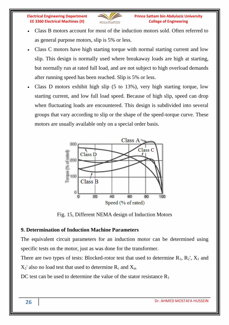
8. NEMA Design (Induction Motor Classes)
NEMA (National Electrical Manufacturers Association) have classified electrical
induction motors into four different NEMA Classes where torques and starting-load
inertia are important criterions as shown in Fig 15. This figure illustrates typical speed
torque curves for Class A, B, C, and D motors.
• Class A motors have a higher breakdown torque than Class B motors and are
usually designed for a specific use. Slip is 5%, or less.
Prince Sattam bin Abdulaziz University College of Engineering
Electrical Engineering Department EE 3360 Electrical Machines (II)
26 Dr. AHMED MOSTAFA HUSSEIN
• Class B motors account for most of the induction motors sold. Often referred to
as general purpose motors, slip is 5% or less.
• Class C motors have high starting torque with normal starting current and low
slip. This design is normally used where breakaway loads are high at starting,
but normally run at rated full load, and are not subject to high overload demands
after running speed has been reached. Slip is 5% or less.
• Class D motors exhibit high slip (5 to 13%), very high starting torque, low
starting current, and low full load speed. Because of high slip, speed can drop
when fluctuating loads are encountered. This design is subdivided into several
groups that vary according to slip or the shape of the speed-torque curve. These
motors are usually available only on a special order basis.
Fig. 15, Different NEMA design of Induction Motors
9. Determination of Induction Machine Parameters
The equivalent circuit parameters for an induction motor can be determined using
specific tests on the motor, just as was done for the transformer.
There are two types of tests: Blocked-rotor test that used to determine R1, R2', X1 and
X2' also no load test that used to determine Rc and Xm
DC test can be used to determine the value of the stator resistance R1

Prince Sattam bin Abdulaziz University College of Engineering
Electrical Engineering Department EE 3360 Electrical Machines (II)
27 Dr. AHMED MOSTAFA HUSSEIN
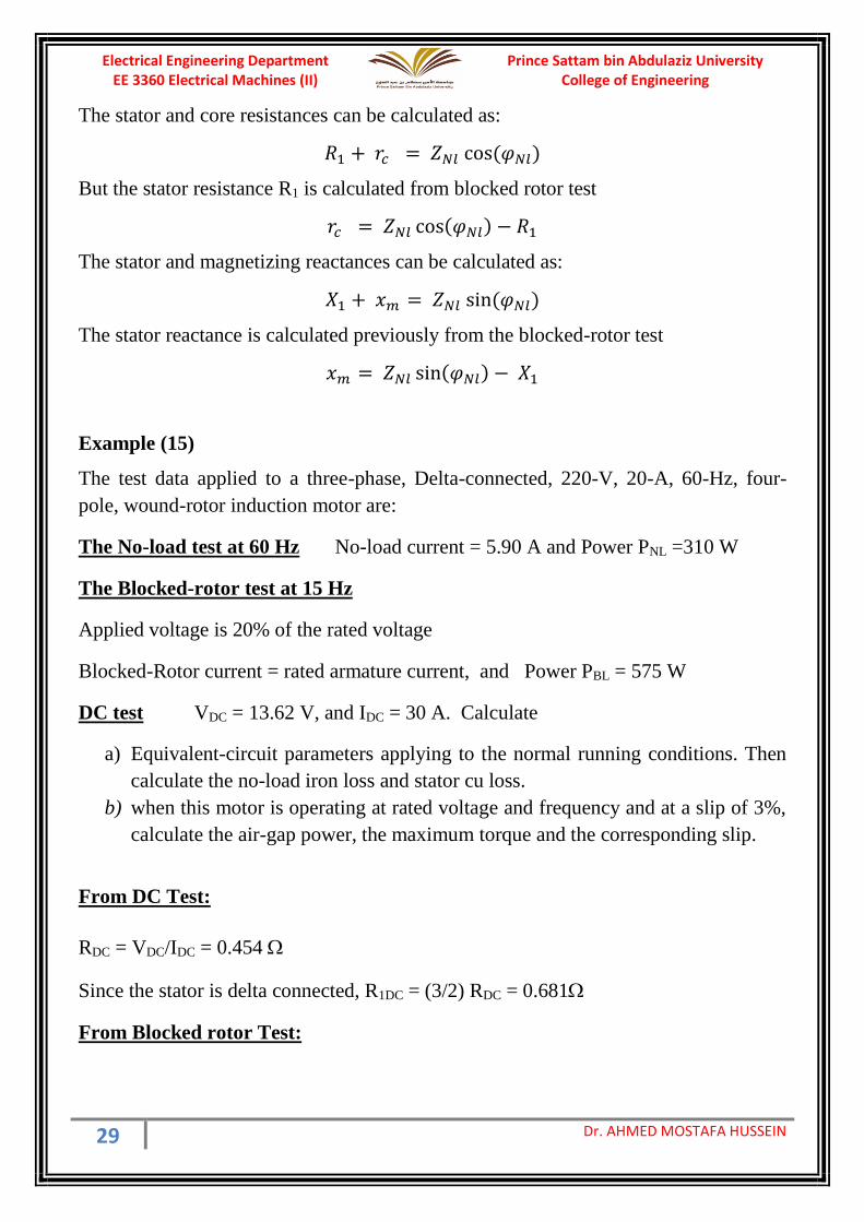
9.1 Blocked Rotor (Short-Circuit) Test
The rotor is blocked to prevent rotation and balanced voltages are applied to the stator
terminals at a frequency of 25 percent of the rated frequency (ftest) at a reduced voltage
such that the rated current is achieved. Current, voltage and power are measured at the
motor input.
Since the rotor is standstill, the slip is unity. Thus, the value of the load R2'(1-S)/S is
zero and the rotor circuit is considered as short circuit and the rotor current is much
larger than the magnetizing current, so the magnetizing branch can be neglected as
shown in Fig. 16. On the other hand, since the slip is unity, then the rotor frequency
equals the stator frequency (ftest).
Fig. 16, Induction motor equivalent circuit at blocked rotor test
The power (PBl) & the voltage (VBl) and current (IBl) at blocked rotor test are
measured.
The motor impedance ZBl can be calculated from
𝑍𝐵𝑙 =𝑉𝐵𝑙
𝐼𝐵𝑙
The motor power factor can be calculated as
cos(𝜑𝐵𝑙) = 𝑃𝐵𝑙
3 𝑉𝐵𝑙𝐼𝐵𝑙
The stator and rotor resistances can be calculated as:
𝑅1 + 𝑅2′ = 𝑍𝐵𝑙 cos (𝜑𝐵𝑙)
Assuming R1 and R2' are equal
𝑅1 = 𝑅2′ =
𝑍𝐵𝑙 cos (𝜑𝐵𝑙)
2
The stator and rotor reactances can be calculated as
𝑋𝐵𝑙 = 𝑋1 + 𝑋2′ = 𝑍𝐵𝑙 sin (𝜑𝐵𝑙)

Prince Sattam bin Abdulaziz University College of Engineering
Electrical Engineering Department EE 3360 Electrical Machines (II)
28 Dr. AHMED MOSTAFA HUSSEIN
According to the motor class X1 and X2' can be calculated as
Squirrel-cage Class A X1 = 0.5XBl X2 = 0.5 XBl
Squirrel-cage Class B X1 = 0.4 XBl X2 = 0.6 XBl
Squirrel-cage Class C X1 = 0.3 XBl X2 = 0.7 XBl
Squirrel-cage Class D X1 = 0.5 XBl X2 = 0.5 XBl
Wound rotor X1 = 0.5 XBl X2 = 0.5 XBl
9.2 No-Load (Open-Circuit) Test
Balanced voltages are applied to the stator terminals at the rated frequency with the
rotor uncoupled from any mechanical load. Current, voltage and power are measured
at the motor input. The losses in the no-load test are those due to core losses, copper
losses, windage and friction losses.
The slip of the induction motor at no-load is very small. Thus, the value of the load
resistance R2'(1-S)/S is very high and the rotor circuit is considered as open circuit as
shown in Fig. 17.
Fig. 17, motor equivalent circuit at no load
The input power measured in the no-load test is equal to the stator copper losses plus
the core loss plus the rotational losses.
The power (PNl) & the voltage (VNl) and current (INl) at No-Load test are measured.
The motor impedance ZNl can be calculated from
𝑍𝑁𝑙 =𝑉𝑁𝑙
𝐼𝑁𝑙
The motor power factor can be calculated as
cos(𝜑𝑁𝑙) = 𝑃𝑁𝑙
3 𝑉𝑁𝑙𝐼𝑁𝑙
Prince Sattam bin Abdulaziz University College of Engineering
Electrical Engineering Department EE 3360 Electrical Machines (II)
29 Dr. AHMED MOSTAFA HUSSEIN
The stator and core resistances can be calculated as:
𝑅1 + 𝑟𝑐 = 𝑍𝑁𝑙 cos (𝜑𝑁𝑙)
But the stator resistance R1 is calculated from blocked rotor test
𝑟𝑐 = 𝑍𝑁𝑙 cos(𝜑𝑁𝑙) − 𝑅1
The stator and magnetizing reactances can be calculated as:
𝑋1 + 𝑥𝑚 = 𝑍𝑁𝑙 sin (𝜑𝑁𝑙)
The stator reactance is calculated previously from the blocked-rotor test
𝑥𝑚 = 𝑍𝑁𝑙 sin(𝜑𝑁𝑙) − 𝑋1
Example (15)
The test data applied to a three-phase, Delta-connected, 220-V, 20-A, 60-Hz, four-
pole, wound-rotor induction motor are:
The No-load test at 60 Hz No-load current = 5.90 A and Power PNL =310 W
The Blocked-rotor test at 15 Hz
Applied voltage is 20% of the rated voltage
Blocked-Rotor current = rated armature current, and Power PBL = 575 W
DC test VDC = 13.62 V, and IDC = 30 A. Calculate
a) Equivalent-circuit parameters applying to the normal running conditions. Then
calculate the no-load iron loss and stator cu loss.
b) when this motor is operating at rated voltage and frequency and at a slip of 3%,
calculate the air-gap power, the maximum torque and the corresponding slip.
From DC Test:
RDC = VDC/IDC = 0.454
Since the stator is delta connected, R1DC = (3/2) RDC = 0.681
From Blocked rotor Test:
Prince Sattam bin Abdulaziz University College of Engineering
Electrical Engineering Department EE 3360 Electrical Machines (II)
30 Dr. AHMED MOSTAFA HUSSEIN
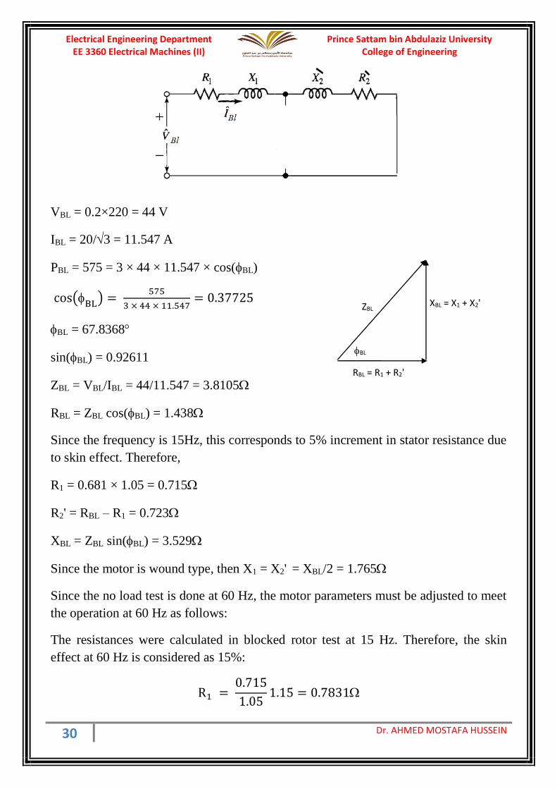
VBL = 0.2×220 = 44 V
IBL = 20/3 = 11.547 A
PBL = 575 = 3 × 44 × 11.547 × cos(BL)
cos(BL
) = 575
3 × 44 × 11.547= 0.37725
BL = 67.8368
sin(BL) = 0.92611
ZBL = VBL/IBL = 44/11.547 = 3.8105
RBL = ZBL cos(BL) = 1.438
Since the frequency is 15Hz, this corresponds to 5% increment in stator resistance due
to skin effect. Therefore,
R1 = 0.681 × 1.05 = 0.715
R2' = RBL – R1 = 0.723
XBL = ZBL sin(BL) = 3.529
Since the motor is wound type, then X1 = X2' = XBL/2 = 1.765
Since the no load test is done at 60 Hz, the motor parameters must be adjusted to meet
the operation at 60 Hz as follows:
The resistances were calculated in blocked rotor test at 15 Hz. Therefore, the skin
effect at 60 Hz is considered as 15%:
R1 = 0.715
1.051.15 = 0.7831
RBL = R1 + R2'
XBL = X1 + X2' ZBL
BL
Prince Sattam bin Abdulaziz University College of Engineering
Electrical Engineering Department EE 3360 Electrical Machines (II)
31 Dr. AHMED MOSTAFA HUSSEIN
R′2 = 0.723
1.051.15 = 0.792
X1 = X′2 = 1.765
1560 = 7.06
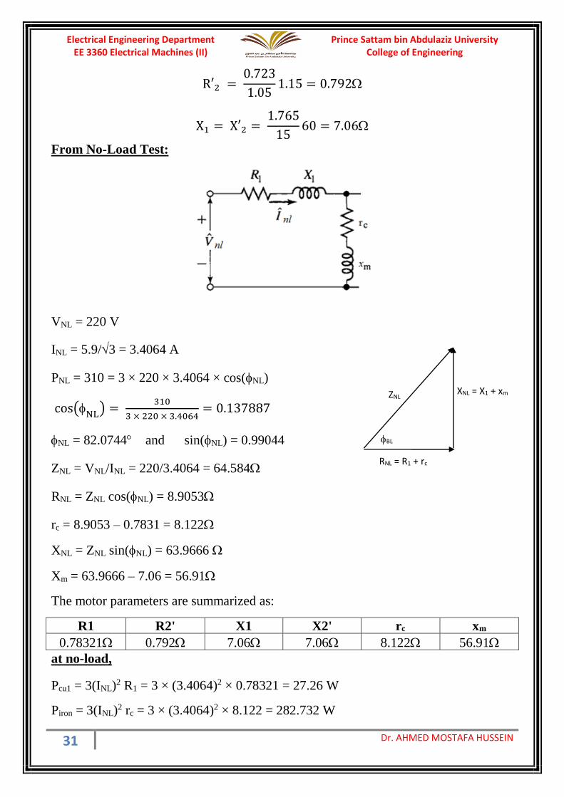
From No-Load Test:
VNL = 220 V
INL = 5.9/3 = 3.4064 A
PNL = 310 = 3 × 220 × 3.4064 × cos(NL)
cos(NL
) = 310
3 × 220 × 3.4064= 0.137887
NL = 82.0744 and sin(NL) = 0.99044
ZNL = VNL/INL = 220/3.4064 = 64.584
RNL = ZNL cos(NL) = 8.9053
rc = 8.9053 – 0.7831 = 8.122
XNL = ZNL sin(NL) = 63.9666
Xm = 63.9666 – 7.06 = 56.91
The motor parameters are summarized as:
R1 R2' X1 X2' rc xm
0.78321 0.792 7.06 7.06 8.122 56.91
at no-load,
Pcu1 = 3(INL)2 R1 = 3 × (3.4064)2 × 0.78321 = 27.26 W
Piron = 3(INL)2 rc = 3 × (3.4064)2 × 8.122 = 282.732 W
RNL = R1 + rc
XNL = X1 + xm ZNL
BL
Prince Sattam bin Abdulaziz University College of Engineering
Electrical Engineering Department EE 3360 Electrical Machines (II)
32 Dr. AHMED MOSTAFA HUSSEIN
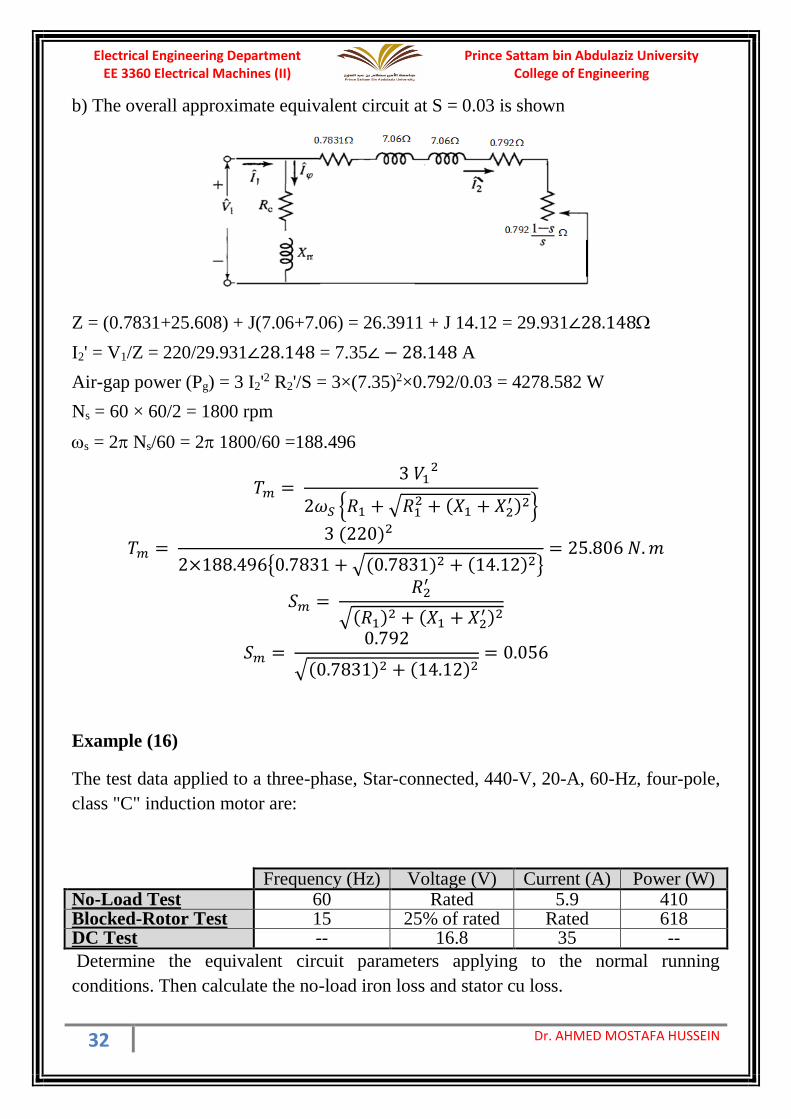
b) The overall approximate equivalent circuit at S = 0.03 is shown
Z = (0.7831+25.608) + J(7.06+7.06) = 26.3911 + J 14.12 = 29.931∠28.148
I2' = V1/Z = 220/29.931∠28.148 = 7.35∠ − 28.148 A
Air-gap power (Pg) = 3 I2'2 R2'/S = 3×(7.35)2×0.792/0.03 = 4278.582 W
Ns = 60 × 60/2 = 1800 rpm
s = 2 Ns/60 = 2 1800/60 =188.496
𝑇𝑚 = 3 𝑉1
2
2𝜔𝑆 𝑅1 + √𝑅12 + (𝑋1 + 𝑋2
′ )2
𝑇𝑚 = 3 (220)2
2×188.4960.7831 + √(0.7831)2 + (14.12)2= 25.806 𝑁. 𝑚
𝑆𝑚 = 𝑅2
′
√(𝑅1)2 + (𝑋1 + 𝑋2′ )2
𝑆𝑚 = 0.792
√(0.7831)2 + (14.12)2= 0.056
Example (16)
The test data applied to a three-phase, Star-connected, 440-V, 20-A, 60-Hz, four-pole,
class "C" induction motor are:
Frequency (Hz) Voltage (V) Current (A) Power (W) No-Load Test 60 Rated 5.9 410 Blocked-Rotor Test 15 25% of rated Rated 618 DC Test -- 16.8 35 --
Determine the equivalent circuit parameters applying to the normal running
conditions. Then calculate the no-load iron loss and stator cu loss.
Prince Sattam bin Abdulaziz University College of Engineering
Electrical Engineering Department EE 3360 Electrical Machines (II)
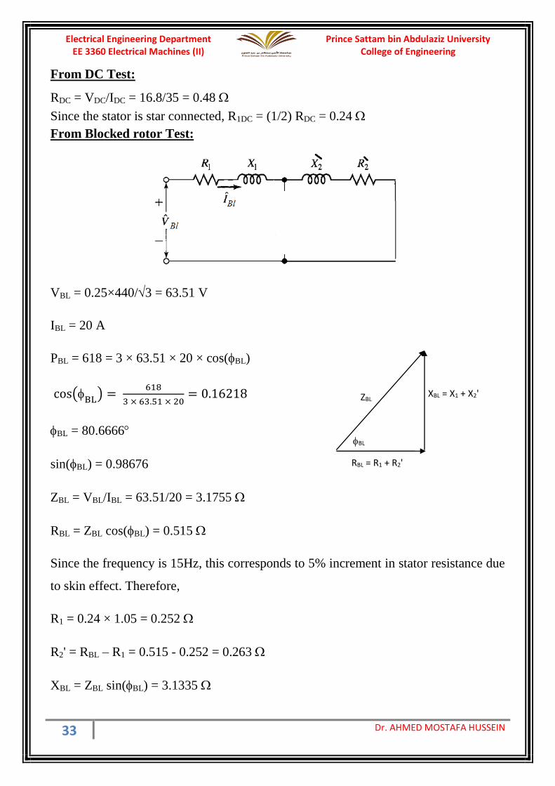
33 Dr. AHMED MOSTAFA HUSSEIN
From DC Test:
RDC = VDC/IDC = 16.8/35 = 0.48
Since the stator is star connected, R1DC = (1/2) RDC = 0.24
From Blocked rotor Test:
VBL = 0.25×440/3 = 63.51 V
IBL = 20 A
PBL = 618 = 3 × 63.51 × 20 × cos(BL)
cos(BL
) = 618
3 × 63.51 × 20= 0.16218
BL = 80.6666
sin(BL) = 0.98676
ZBL = VBL/IBL = 63.51/20 = 3.1755
RBL = ZBL cos(BL) = 0.515
Since the frequency is 15Hz, this corresponds to 5% increment in stator resistance due
to skin effect. Therefore,
R1 = 0.24 × 1.05 = 0.252
R2' = RBL – R1 = 0.515 - 0.252 = 0.263
XBL = ZBL sin(BL) = 3.1335
RBL = R1 + R2'
XBL = X1 + X2' ZBL
BL

Prince Sattam bin Abdulaziz University College of Engineering
Electrical Engineering Department EE 3360 Electrical Machines (II)
34 Dr. AHMED MOSTAFA HUSSEIN
Since the motor is class "C", then
X1 = 0.3 XBL = 0.3× 3.1335 = 0.94 Ω
X2' = 0.7 XBL = 0.7× 3.1335 = 2.19345 Ω
Since the no load test is done at 60 Hz, the motor parameters must be adjusted to meet
the operation at 60 Hz as follows:
The resistances were calculated in blocked rotor test at 15 Hz. Therefore, the skin
effect at 60 Hz is considered as 15%:
R1 = 0.252
1.051.15 = 0.276
R′2 = 0.263
1.051.15 = 0.288
X1 = 0.94
1560 = 3.76
X′2 =2.19345
1560 = 8.7738
From No-Load Test:
VNL = 440 /3 = 254.034V
INL = 5.9 A
PNL = 410 = 3 × 254.034 × 5.9 × cos(NL)
cos(NL
) = 410
3 × 254.034 × 5.9= 0.0912
RNL = R1 + rc
XNL = X1 + xm ZNL
BL
Prince Sattam bin Abdulaziz University College of Engineering
Electrical Engineering Department EE 3360 Electrical Machines (II)
35 Dr. AHMED MOSTAFA HUSSEIN
NL = 84.7683 and sin(NL) = 0.9958
ZNL = VNL/INL = 254.034/5.9 = 43.0566
RNL = ZNL cos(NL) = 3.9268
rc = 3.9268 – 0.276 = 3.6508
XNL = ZNL sin(NL) = 42.8758
Xm = 42.8758 – 3.76 = 39.1158
The motor parameters are summarized as:
R1 R2' X1 X2' rc xm
0.276 0.288 3.76 8.7738 3.6508 39.1158
at no-load,
Pcu1 = 3(INL)2 R1 = 3 × (5.9)2 × 0.276 = 28.823 W
Piron = 3(INL)2 rc = 3 × (5.9)2 × 3.6508 = 381.253 W
Example:
The following data apply to a 125-kW, 2300-V, 3-phase, Y-connected, 4-pole, 60-Hz
squirrel-cage class B, induction motor:
DC Test: DC resistance between stator terminals is 2.24
No-load test (60 Hz): Line current = 7.7 A, Three-phase power = 2870 W
Blocked-rotor test (15 Hz): Line current = 50.3 A, and Three-phase power = 18.2 kW
a) Calculate the equivalent-circuit parameters in ohms.
b) Based on approximate equivalent circuit, compute the rotor current, input power
factor, air-gap power and the maximum slip when the motor is operating at rated
voltage & frequency at slip of 2.95 %.
(Consider the skin effect at 60 Hz is 20% and at 15 Hz is 7%)
From DC Test:
RDC = VDC/IDC = 2.24
Since the stator is star connected, R1DC = (1/2) RDC = 1.12
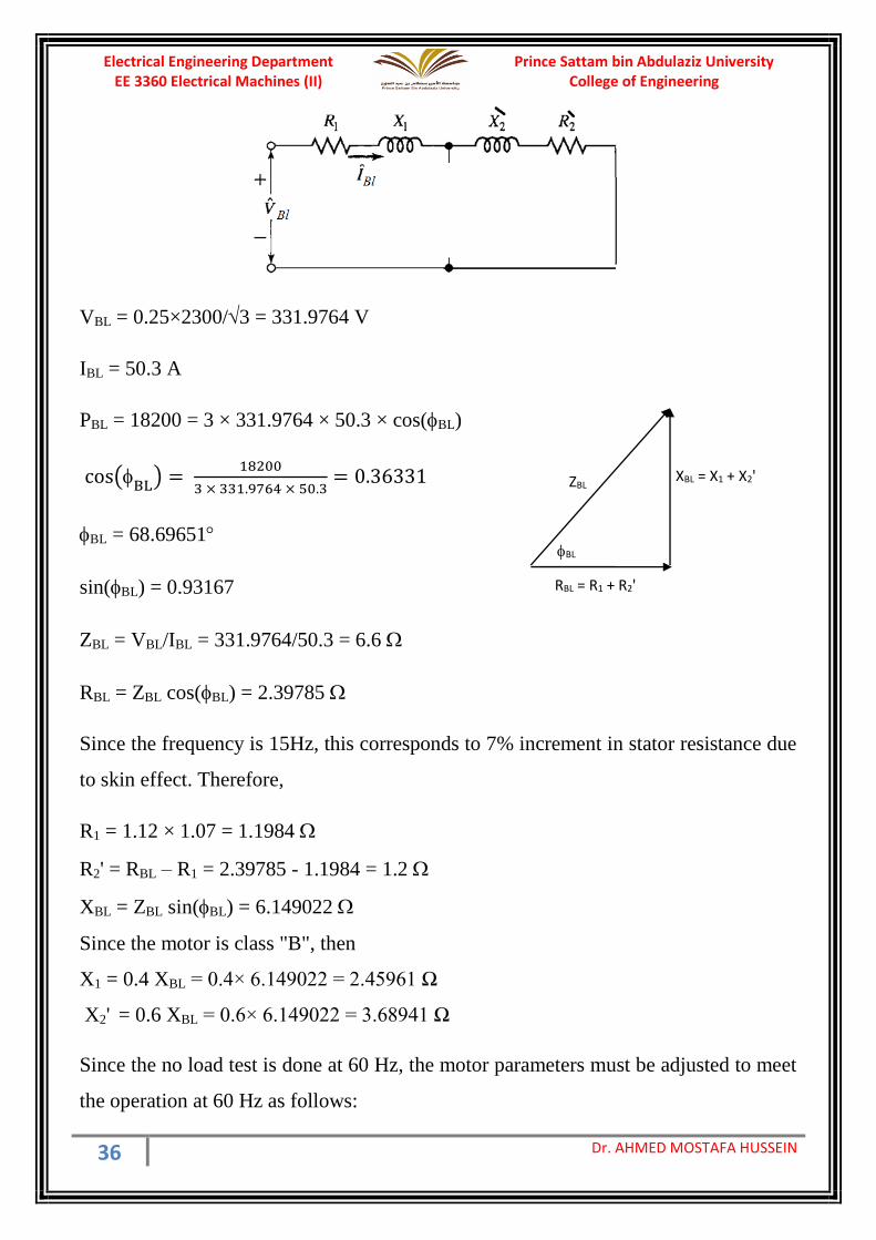
From Blocked rotor Test:
Prince Sattam bin Abdulaziz University College of Engineering
Electrical Engineering Department EE 3360 Electrical Machines (II)
36 Dr. AHMED MOSTAFA HUSSEIN
VBL = 0.25×2300/3 = 331.9764 V
IBL = 50.3 A
PBL = 18200 = 3 × 331.9764 × 50.3 × cos(BL)
cos(BL
) = 18200
3 × 331.9764 × 50.3= 0.36331
BL = 68.69651
sin(BL) = 0.93167
ZBL = VBL/IBL = 331.9764/50.3 = 6.6
RBL = ZBL cos(BL) = 2.39785
Since the frequency is 15Hz, this corresponds to 7% increment in stator resistance due
to skin effect. Therefore,
R1 = 1.12 × 1.07 = 1.1984
R2' = RBL – R1 = 2.39785 - 1.1984 = 1.2
XBL = ZBL sin(BL) = 6.149022
Since the motor is class "B", then
X1 = 0.4 XBL = 0.4× 6.149022 = 2.45961 Ω
X2' = 0.6 XBL = 0.6× 6.149022 = 3.68941 Ω
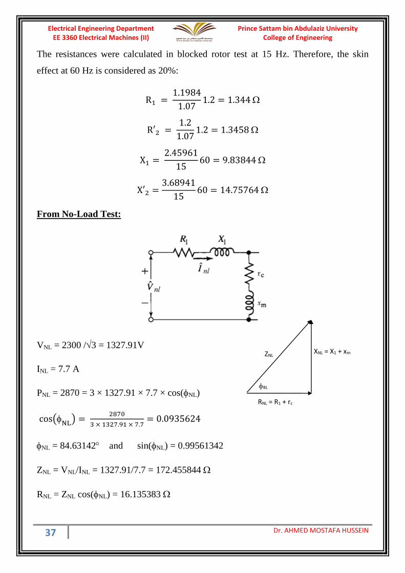
Since the no load test is done at 60 Hz, the motor parameters must be adjusted to meet
the operation at 60 Hz as follows:
RBL = R1 + R2'
XBL = X1 + X2' ZBL
BL
Prince Sattam bin Abdulaziz University College of Engineering
Electrical Engineering Department EE 3360 Electrical Machines (II)
37 Dr. AHMED MOSTAFA HUSSEIN
The resistances were calculated in blocked rotor test at 15 Hz. Therefore, the skin
effect at 60 Hz is considered as 20%:
R1 = 1.1984
1.071.2 = 1.344
R′2 = 1.2
1.071.2 = 1.3458
X1 = 2.45961
1560 = 9.83844
X′2 =3.68941
1560 = 14.75764
From No-Load Test:
VNL = 2300 /3 = 1327.91V
INL = 7.7 A
PNL = 2870 = 3 × 1327.91 × 7.7 × cos(NL)
cos(NL
) = 2870
3 × 1327.91 × 7.7= 0.0935624
NL = 84.63142 and sin(NL) = 0.99561342
ZNL = VNL/INL = 1327.91/7.7 = 172.455844
RNL = ZNL cos(NL) = 16.135383
RNL = R1 + rc
XNL = X1 + xm ZNL
BL
Prince Sattam bin Abdulaziz University College of Engineering
Electrical Engineering Department EE 3360 Electrical Machines (II)
38 Dr. AHMED MOSTAFA HUSSEIN
rc = RNL – R1 = 16.135383 – 1.344 = 14.7914
XNL = ZNL sin(NL) = 171.7
xm = XNL – X1 = 171.7 – 9.83844 = 161.86156
The motor parameters are summarized as:
R1 R2' X1 X2' rc xm
1.344 1.3458 9.83844 14.75764 14.7914 161.86156
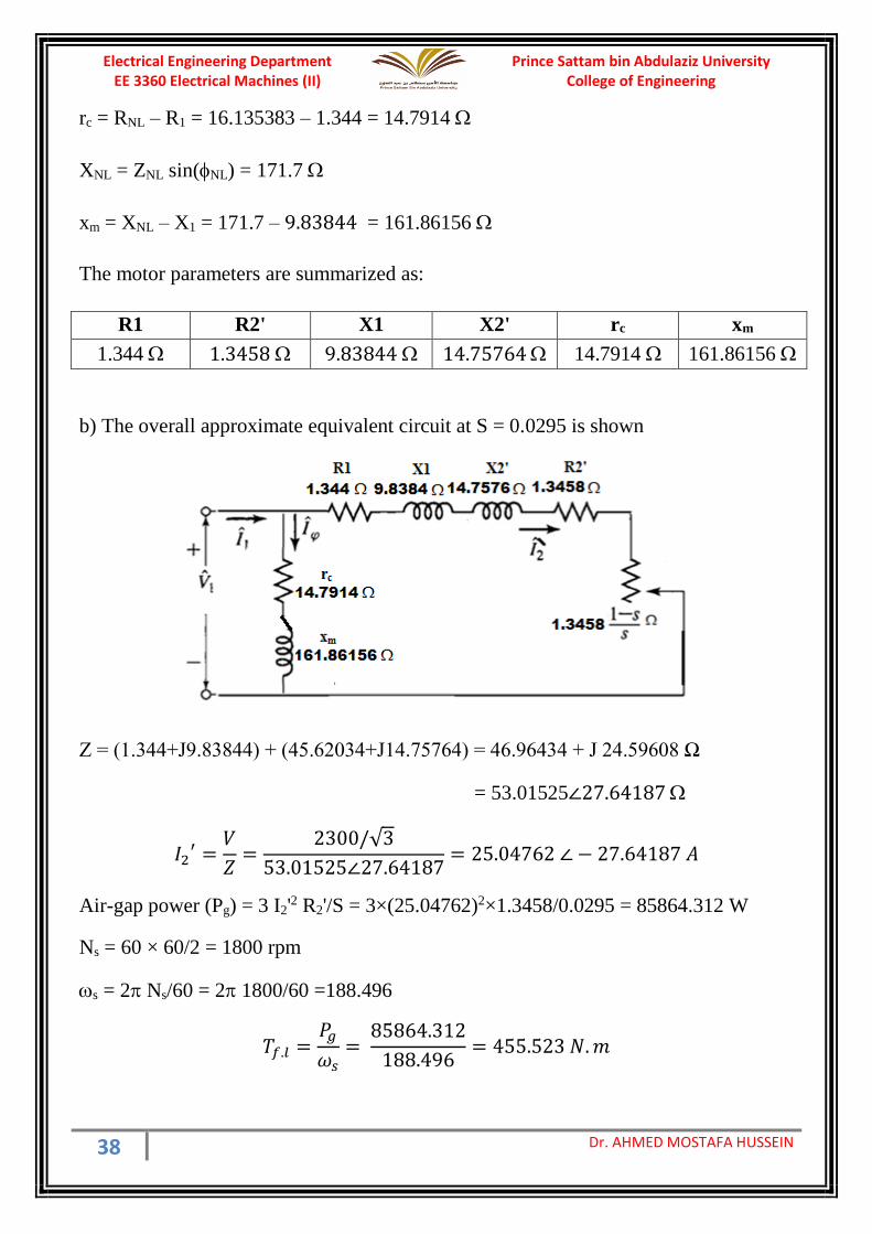
b) The overall approximate equivalent circuit at S = 0.0295 is shown
Z = (1.344+J9.83844) + (45.62034+J14.75764) = 46.96434 + J 24.59608 Ω
= 53.01525∠27.64187
𝐼2′ =
𝑉
𝑍=
2300/√3
53.01525∠27.64187= 25.04762 ∠ − 27.64187 𝐴
Air-gap power (Pg) = 3 I2'2 R2'/S = 3×(25.04762)2×1.3458/0.0295 = 85864.312 W
Ns = 60 × 60/2 = 1800 rpm
s = 2 Ns/60 = 2 1800/60 =188.496
𝑇𝑓.𝑙 =𝑃𝑔
𝜔𝑠=
85864.312
188.496= 455.523 𝑁. 𝑚
Prince Sattam bin Abdulaziz University College of Engineering
Electrical Engineering Department EE 3360 Electrical Machines (II)
39 Dr. AHMED MOSTAFA HUSSEIN
𝑇𝑚 = 3 𝑉1
2
2𝜔𝑆 𝑅1 + √𝑅12 + (𝑋1 + 𝑋2
′ )2
𝑇𝑚 = 3 (1327.91)2
2×188.4961.344 + √(1.344)2 + (24.59608)2= 540.18334 𝑁. 𝑚
𝑆𝑚 = 𝑅2
′
√(𝑅1)2 + (𝑋1 + 𝑋2′ )2
𝑆𝑚 = 1.3458
√(1.344)2 + (24.59608)2= 0.0546
Example (17):
A 460-V, 60-Hz, four-pole, Y-connected wound-rotor induction motor has the
following parameters in ohms per phase referred to the stator circuit:
R1 = 0.641Ω R2' = 0.332 Ω X1 = 1.106 Ω X2' = 0.464 Ω Xm= 26.3 Ω
Based on approximate equivalent circuit, and neglecting the iron loss:
a) What is the maximum torque of this motor? At what speed and slip does it occur?
b) What is the starting torque of this motor?
c) If the rotational loss is 350W, what is the full-load efficiency? Consider Sf.l=0.05
d) If the rotor resistance is doubled, what is the maximum torque and max slip?
e) What is the new starting torque of the motor?
a) the maximum slip:
𝑆𝑚 = 𝑅2
′
√(𝑅1)2 + (𝑋1 + 𝑋2′ )2
=0.332
√(0.641)2 + (1.57)2= 0.1958
Ns = 60×f / P = 60×60 / 2 = 1800 rpm
** The rotor speed (N) = Ns (1-S) = 1800 (1-0.1958) = 1447.6 rpm #
s = 188.496 rad/s
𝑇𝑚 = 3 𝑉1
2
2𝜔𝑆 𝑅1 + √𝑅12 + (𝑋1 + 𝑋2
′ )2=
3×(265.5811)2
2×188.496 0.641 + √(0.641)2 + (1.57)2
= 240.1925 𝑁. 𝑚
b) At starting, S=1
Prince Sattam bin Abdulaziz University College of Engineering
Electrical Engineering Department EE 3360 Electrical Machines (II)
40 Dr. AHMED MOSTAFA HUSSEIN
𝐼2′ =
𝑉1
√(𝑅1 +𝑅2
′
𝑆 )2
+ (𝑋1 + 𝑋2′ )2
=265.5811
√(0.973)2 + (1.57)2= 143.7859 𝐴
𝑇𝑠𝑡 = 3 𝐼2
′ 2 𝑅2′
𝑆
𝜔𝑆=
3×(143.7859)2×0.332
188.496= 109.242 𝑁. 𝑚
c) At full load, S=0.05
𝐼2′ =
𝑉1
√(𝑅1 +𝑅2
′
𝑆 )2
+ (𝑋1 + 𝑋2′ )2
=265.5811
√(7.281)2 + (1.57)2= 35.6564 𝐴
𝑃𝑔 = 3 𝐼2′ 2 𝑅2
′
𝑆= 3×(35.6564)2×
0.332
0.05= 25325.867 𝑊
𝑃𝑚𝑒𝑐ℎ(𝐺𝑟𝑜𝑠𝑠) = 3 𝐼2′ 2 𝑅2
′ (1 − 𝑆)
𝑆= 3×(35.6564)2×
0.332(1 − 0.05)
0.05= 24059.5736 𝑊
𝑃𝑚𝑒𝑐ℎ(𝑁𝑒𝑡) = 24059.5736 − 350 = 23709.5736 𝑊
𝑃𝑐𝑢1 = 3 𝐼2′ 2
𝑅1 = 3×(35.6564)2×0.641 = 2444.8616 𝑊
𝜂 =23709.5736
25325.867 + 2444.8616×100 = 85.3761%
d) The rotor resistance is doubled R2' = 0.664 Ω
𝑆𝑚 = 𝑅2
′
√(𝑅1)2 + (𝑋1 + 𝑋2′ )2
=0.664
√(0.641)2 + (1.57)2= 0.3916
Max. torque is not changed Tm = 240.1925 N.m
e) At starting, S=1
𝐼2′ =
𝑉1
√(𝑅1 +𝑅2
′
𝑆 )2
+ (𝑋1 + 𝑋2′ )2
=265.5811
√(1.305)2 + (1.57)2= 130.088 𝐴
𝑇𝑠𝑡 = 3 𝐼2
′ 2 𝑅2′
𝑆
𝜔𝑆=
3×(130.088)2×0.664
188.496= 178.8387 𝑁. 𝑚

Prince Sattam bin Abdulaziz University College of Engineering
Electrical Engineering Department EE 3360 Electrical Machines (II)
41 Dr. AHMED MOSTAFA HUSSEIN
Sheet 4(Three-Phase Induction Machines)
Problem (1)
A three-phase, Y-connected, 220-V (line-to-line), 7.5-kW, 60-Hz, 6-pole induction
motor has the following parameter values in Ω/phase referred to the stator:
R1 = 0.294Ω R2' = 0.144 Ω Rc = 415 Ω
X1 = 0.503 Ω X2' = 0.209 Ω Xm = 13.25 Ω
The total friction and windage losses may be assumed to be constant at 403 W,
independent of load. For a slip of 2 %, and based on EXACT equivalent circuit,
compute the rotor speed, output torque and power, stator current, power factor, iron
loss, electro-magnetic torque & efficiency when the motor is operated at rated voltage
and frequency.
Problem (2)
A three-phase, four-pole, 30hp, 220V, 60Hz, Y-connected induction motor draws a
current of 77A from the line source at a power factor of 0.88. At this operating
condition, the motor losses are known to be the following:
Stator copper losses: PCu1=1,033W
Rotor copper losses: PCu2=1,299W
Stator core losses: Piron=485W
Rotational losses: Pf+w=540W (friction, windage). Determine:
a) power transferred across the air gap,
b) slip expressed per unit and in rpm,
c) mechanical power developed in watts,
d) horsepower output,
e) motor speed in rpm and radians per second,
f) torque at the output shaft,
g) efficiency of operation at the stated condition.
Problem (3)
A three-phase, four-pole, 50hp, 480V, 60Hz, Y-connected induction motor has the
following parameters per phase:

Prince Sattam bin Abdulaziz University College of Engineering
Electrical Engineering Department EE 3360 Electrical Machines (II)
42 Dr. AHMED MOSTAFA HUSSEIN
Rc =190Ω, Xm =15Ω, R1 = 0.10Ω, X1 = 0.35Ω, R2′= 0.12Ω, X2′= 0.40Ω .
It is known that the rotational losses amount is 950W. Calculate:
a) the starting line current when starting from rest under full line voltage,
b) the input line current under no load conditions,
c) the slip under no load conditions expressed per unit and in rpm.
When the motor operates at a slip of 3.9%, find:
d) the input line current and power factor,
e) the horsepower output,
f) the efficiency.
Problem (4)
A three-phase, Y-connected, 460-V (line-line), 25-kW, 60-Hz, four-pole induction
motor has the following equivalent-circuit parameters in ohms per phase referred to
the stator:
R1=0.103 R2'=0.225 X1=1.10 X2'=1.13 Xm=59.4
The total friction and windage losses may be assumed constant at 265 W, and the core
loss may be assumed to be equal to 220 W. With the motor connected directly to a
460-V source, compute the speed, output shaft torque and power, input power and
power factor and efficiency for slips of 1, 2 and 3 percent.
Hint: You can represent the core loss by a resistance Rc connected in parallel with the
magnetizing reactance Xm.
Problem (5)
A 15-kW, 230-V, three-phase, Y-connected, 60-Hz, four-pole squirrel-cage induction
motor develops full-load torque at a slip of 3.5 percent when operated at rated voltage
and frequency. If the rotational and core losses are neglected. The following motor
parameters, in ohms per phase, have been obtained:
R1 = 0.21 X1= X2' = 0.26 Xm = 10.1
Determine the maximum torque at rated voltage and frequency, the slip at maximum
torque, and the starting torque at rated voltage and frequency.
Problem (6)

Prince Sattam bin Abdulaziz University College of Engineering
Electrical Engineering Department EE 3360 Electrical Machines (II)
43 Dr. AHMED MOSTAFA HUSSEIN
A three-phase induction motor, operating at rated voltage and frequency, has a starting
torque of 135 percent and a maximum torque of 220 percent, both with respect to its
rated-load torque. Neglecting the effects of stator resistance and rotational losses and
assuming constant rotor resistance, determine:
a. the slip at maximum torque.
b. the slip at rated load.
c. the rotor current at starting (as a percentage of rotor current at rated load).
Problem (7)
When operated at rated voltage and frequency, a three-phase squirrel-cage induction
motor delivers full load at a slip of 8.7 percent and develops a maximum torque of 230
percent of full load at a slip of 55 percent. Neglect core and rotational losses and
assume that the rotor resistance and inductance remain constant, independent of slip.
Determine the torque at starting, with rated voltage and frequency, in per unit based
upon its full-load value.
Problem (8)
A 50 Hz, 8 pole induction motor has full load slip of 4%. The rotor resistance and
stand still reactance are 0.01 and 0.1 Ω per phase respectively. Find:
i) The speed at which maximum torque occurs
ii) The ratio of maximum torque to full load torque
Problem (9)
The following test data apply to a 7.5-hp, 3-phase Y, 220-V, 19-A, 60-Hz, 4-pole
induction motor of design class C (high-starting-torque, low-starting current type):
Test 1: No-load test at 60 Hz
Applied Line voltage V = 220 V, No-load current = 5.70 A and Power PNL =380 W
Test 2: Blocked-rotor test at 15 Hz
Applied voltage V = 26.5 V line-to-line
Blocked-Rotor current = 18.57 A and Power PBL = 675 W
Test 3: DC resistance per stator phase (measured immediately after test 2)
R1 = 0.262

Prince Sattam bin Abdulaziz University College of Engineering
Electrical Engineering Department EE 3360 Electrical Machines (II)
44 Dr. AHMED MOSTAFA HUSSEIN
Compute the no-load rotational loss and the equivalent-circuit parameters applying to
the normal running conditions. Neglect any effect of core losses.
Problem (10)
The following data apply to a 125-kW, 2300-V, three-phase, four pole, 60-Hz squirrel-
cage induction motor:
Stator-resistance between phase terminals = 2.23
No-load test at rated frequency and voltage:
Line current = 7.7 A, Three-phase power = 2870 W
Blocked-rotor test at 15 Hz:
Line voltage = 268 V, Line current = 50.3 A, and Three-phase power = 18.2 kW
a. Calculate the rotational losses.
b. Calculate the equivalent-circuit parameters in ohms. Assume that Xl =X2'.
c. Compute the stator current, input power and power factor, output power and
efficiency when this motor is operating at rated voltage and frequency at a slip of 2.95
percent.