Embed Size (px)
Citation preview
Univerza v Ljubljani
Fakulteta za elektrotehniko
Electrical Equipment and
Installations in Hazardous
Areas
Student: Tiago da Silva Oliveira;
Student Number: 70080035;
Subject: Electrical Installations and Lighting;
Professor: dr. Grega Bizjak;
Academic year: 2017/2018.
2
Index
1. Introduction 03
2. Area Classification of Hazardous Areas 05
2.1 Safety principles 05
2.2 Hazards and hazardous areas 06
2.3 Basis of area classification 07
2.4 Zonal classification 07
3. Design Philosophy for Equipment and Installations 09
3.1 Equipment definition 10
3.2 Apparatus grouping 11
3.3 Surface temperature classification 12
3.4 Concepts and techniques of explosion protection 14
3.5 Final considerations 16
4. Different Protection Concepts 17
4.1 Intrinsic safety Ex I 17
4.2 Protection type "n" 22
4.3 Increased safety Ex e 24
4.4 Flameproof enclosure Ex d 24
4.5 Molded, sand or oil encapsulation Ex m, Ex q, Ex o 25
4.6 Pressurization Ex p 26
5. Safe Working Practice 27
5.1 Safety observations 28
5.2 Need for inspection and maintenance 29
6. Bibliography 31
3
1
Introduction
Our Industry free from injuries and accidents.
Industrial accidents are as old as industry itself and so are preventive
measures. The Standards for Explosive Areas or Atmospheres have also
evolved diversely worldwide, based on the local needs of the industries for
the overall safe operation of the plants.
Explosion and fire are two of the major constituents of these mishaps.
Depending upon the environment, these can be termed ‘Accidents’ or fade
away as simply ‘incidents’ or ‘Near Misses’ in the safety officers’ statistics.
The first step logically is to start defining and understanding some of the
terms used in the whole scope of the loss prevention in accidents due to
explosion and fire.
FIRE is a rapid oxidation–reduction reaction (combustion) which results in
the production of heat and generally visible light.
EXPLOSION is a violent and sudden expansion of gases produced by rapid
combustion; that very strong force when shut in a small space and generally
associated with a loud, sharp noise and a supersonic shock wave.
For example – bursting of balloons, boiler explosion, combustion of a gas
mixture, detonation of high explosives.
Invariably, electricity is required to run the production processes in any
industry. The fundamental nature of electricity to create a spark or generate
energy leads to a situation where, in an ‘explosive atmosphere’, ignition is
triggered leading to explosion or fire.
4
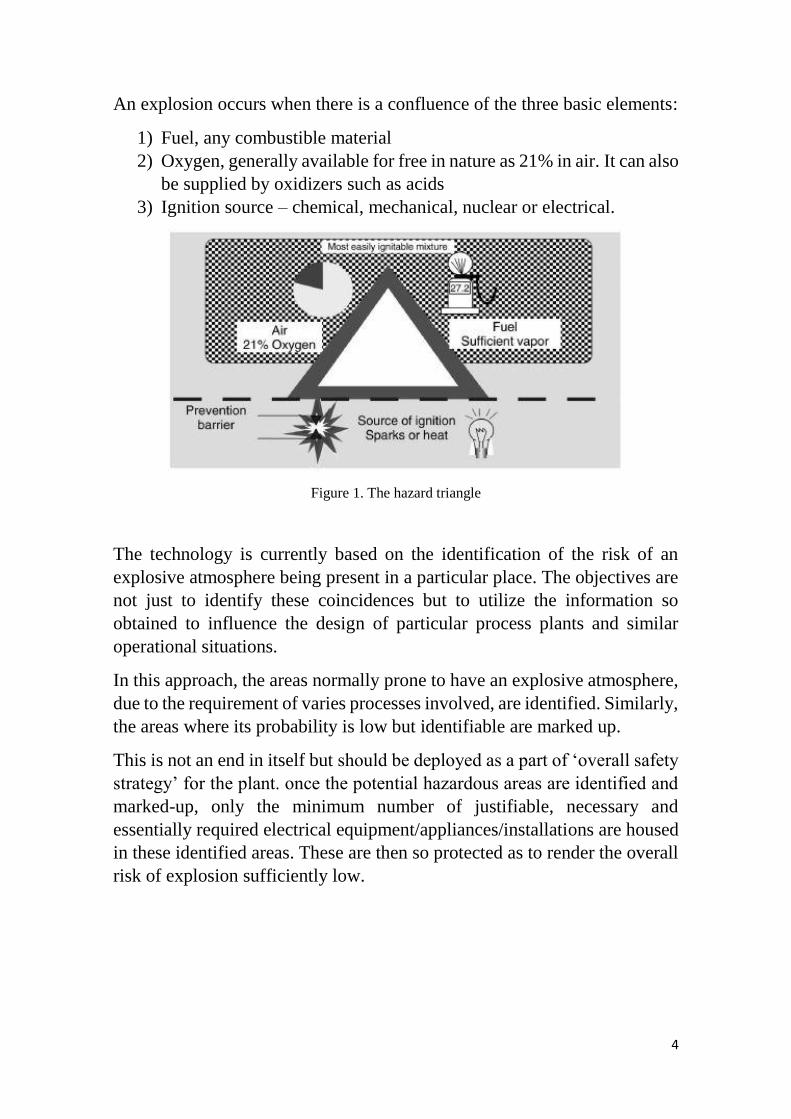
An explosion occurs when there is a confluence of the three basic elements:
1) Fuel, any combustible material
2) Oxygen, generally available for free in nature as 21% in air. It can also
be supplied by oxidizers such as acids
3) Ignition source – chemical, mechanical, nuclear or electrical.
Figure 1. The hazard triangle
The technology is currently based on the identification of the risk of an
explosive atmosphere being present in a particular place. The objectives are
not just to identify these coincidences but to utilize the information so
obtained to influence the design of particular process plants and similar
operational situations.
In this approach, the areas normally prone to have an explosive atmosphere,
due to the requirement of varies processes involved, are identified. Similarly,
the areas where its probability is low but identifiable are marked up.
This is not an end in itself but should be deployed as a part of ‘overall safety
strategy’ for the plant. once the potential hazardous areas are identified and
marked-up, only the minimum number of justifiable, necessary and
essentially required electrical equipment/appliances/installations are housed
in these identified areas. These are then so protected as to render the overall
risk of explosion sufficiently low.
5
2
Area Classification of
Hazardous Areas
What is Area Classification, in relation to hazardous areas?
The process list and identify the areas in the plant where there is possibility
of a conducive atmosphere for explosion or fire to occur. The design,
selection and operation of the equipment has to be influenced in such a way
that the risk of fire or explosion taking place is minimized.
The area classification needs to be used as a tool to achieve the ultimate
objective of ensuring overall plant safety and minimizing the risk of loss to
life and property.
The balance needs to be struck between presence of an explosive and
ignitable environment in an unrestricted area, and the limits prescribed for
its classification, because a too-conservative approach may make the whole
exercise so costly that the viability of the project might be questioned.
It is useful to understand what a non-hazardous (unrestricted) area is. An area
classified as non-hazardous has a small probability of a flammable mixture
being present.
2.1 Safety principles
Hazard and operability studies are carried out during initial design,
renovation and modernization stages. These need to be followed up with
‘periodic risk assessment studies’ during operation of the plant.
6
The ‘safety first’ principle dictates that the quantity of release of flammable
material in and around electrical installations is to be kept to a minimum, in
case it is not possible to eliminate it, so that the extent of area under influence
of hazardous classification is also kept to a minimum.
Even in emergency conditions, emphasis should be placed on weeding out
and eliminating the root cause of the manifestation of ignitable or
combustible atmosphere, i.e.
• Disconnection or isolation of defective electrical equipment;
• Shutdown of processes;
• Isolation of process vessels having ignitable material;
• Containment of spillage.
Then a review needs to be done to augment with additional ventilation,
wherever the process and location of the installation permit, to quickly
reduce the intensity of hazardous atmosphere or environment.
Safety and minimization of risk to life and property demand,
• That ignitable, explosive or hazardous environments be isolated from
the ‘ignition source’;
• That the source of ignition be eliminated.
Whenever it is not possible to reliably and safely implement at least one of
the above, then steps should be taken to put in place procedures whereby the
operations are implemented in such a way so as to minimize the above
conditions occurring simultaneously to an acceptable safe level.
2.2 Hazards and hazardous areas
Hazards can be:
• Urban structure fires;
• Boiling liquid expanding vapor explosions;
• Other explosions;
• Toxic emission;
• The use of electrical equipment in the vicinity of water;
• The risk of personal injury from moving or falling parts;
• The presence of biological hazards.
7
The determination that areas can be classified as hazardous locations is based
on the following:
• The possible presence of an explosive atmosphere such as flammable
gases, vapors or liquids, combustible dusts or ignitable fibers and
flyings;
• The probability that the explosive atmosphere is present when
equipment is operating;
• The ignition-related properties of the explosive atmosphere that is
present.
2.3 Basis of area classification
Area classification cannot be set rigidly into any standard. Each installation
will be different in some respect and therefore each site must be examined
on its individual merits.
There are three situations that can occur in an operating plant with reference
to hazardous areas:
1) A situation where an explosive atmosphere is present always or for
long periods because of operational requirement, i.e. continuous.
2) A situation where explosive atmosphere occurs frequently, or if
infrequently may persist for a considerable time, i.e. primary.
3) A situation in which explosive atmosphere occurs rarely and normally
result from failure of equipment or procedures, i.e. secondary.
The above criteria are used in classifying the areas under ‘Source of Release’
methodology of classification.
2.4 Zonal Classification
Hazardous places are classified in terms of zones on the basis of the
frequency and duration of the occurrence of an explosive atmosphere.
The higher the number in this ‘zonal classification’ the smaller is the risk of
an explosion.
8
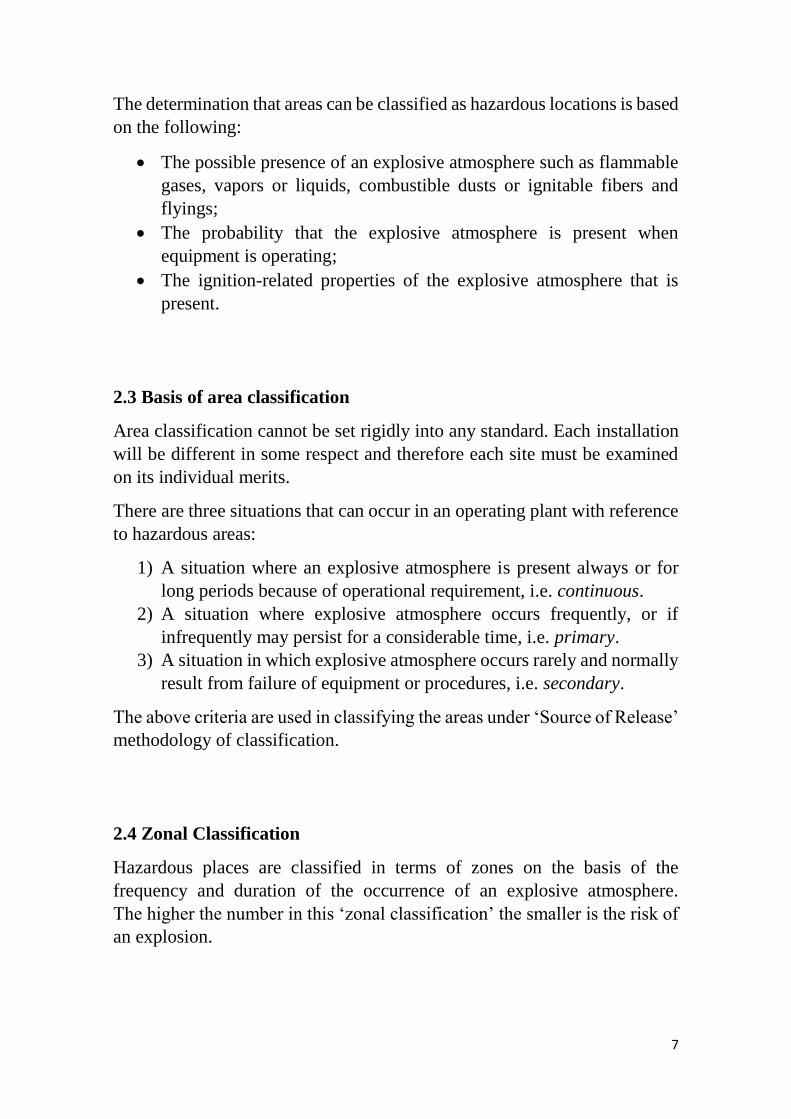
2.4.1 Gases, vapor and mists
For gases, vapours and mists the zone classifications are:
Zone 0
A place in which an explosive atmosphere consisting of a mixture with
air of dangerous substances in the form of gas, vapour or mist is present
continuously or for long periods or frequently.
Zone 1
A place in which an explosive atmosphere consisting of a mixture with
air of dangerous substances in the form of gas, vapour or mist is likely
to occur in normal operation occasionally.
Zone 2
A place in which an explosive atmosphere consisting of a mixture with
air of dangerous substances in the form of gas, vapour or mist is not
likely to occur in normal operation but, if it does occur, will persist for
a short period only.
Table 1. Gases, vapours and mists zone classifications
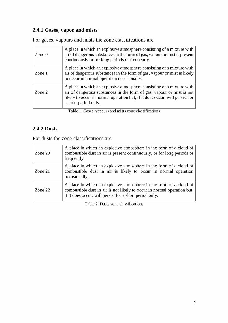
2.4.2 Dusts
For dusts the zone classifications are:
Zone 20
A place in which an explosive atmosphere in the form of a cloud of
combustible dust in air is present continuously, or for long periods or
frequently.
Zone 21
A place in which an explosive atmosphere in the form of a cloud of
combustible dust in air is likely to occur in normal operation
occasionally.
Zone 22
A place in which an explosive atmosphere in the form of a cloud of
combustible dust in air is not likely to occur in normal operation but,
if it does occur, will persist for a short period only.
Table 2. Dusts zone classifications
9
3
Design Philosophy for
Equipment and installations
The use of electricity in potentially explosive areas has been a concern since
the beginning of the 20th century, when these areas were encountered in
mines. To avoid the danger of explosions, protective regulations in the form
of laws, specifications and standards have been developed in most countries
and are aimed at ensuring that a high level of safety is observed. Due to
growing international economic links, extensive progress has been made in
harmonizing the regulations for explosion protection.
In mining, miners underground have always lived under the threat of
firedamp explosions. Herein lies the origin of explosion protection, which
has been consistently developed in industrialized countries and now provides
a high level of safety.
The hazardous areas can vary greatly in size, based on explosive fuel, or use
of equipment. The explosive atmosphere may contain fumes, dust or fibers.
Therefore, it becomes imperative to look into the constructional details of
electrical equipment to be installed in hazardous areas, in order to minimize
the risk of fire or explosion. It is to be noted that despite how well the
construction is, there always remains a residual risk, however small it may
be.
Electrical installations in hazardous areas, involve high initial capital costs
on methods of safeguarding and continuing high inspection and maintenance
costs relative to comparable installations in non-hazardous areas.
Engineers have, that way, a special responsibility, if need be by influencing
basic plant layout and design, to ensure that the need for electrical apparatus
in hazardous areas is kept to a minimum.
10
Where the installation of electrical apparatus in hazardous areas is
unavoidable, special methods of safeguarding must be adopted to avoid
danger.
3.1 Equipment definition
The term ‘equipment’ is defined as:
Any item which contains or constitutes a potential ignition source and which
requires special measures to be incorporated in its design and/or its
installation in order to prevent the ignition source from initiating an
explosion in the surrounding atmosphere.
Also included in the term ‘equipment’ are safety or control devices installed
outside the hazardous area but having an explosion-protection function.
‘Protective systems’ are defined as items that prevent an explosion that has
been initiated from spreading or causing damage. They include flame
arresters, quenching systems, pressure-relief panels and fast-acting shut-off
valves.
Equipment is classified according to:
• The maximum (spark) energy it can produce;
• Its maximum surface temperature.
For equipment to be considered safe for use on a plant, the categories of
classification on the equipment must be the same or ‘better’ than that
required by the plant. The statement of the categories to be encountered on a
plant (by its owner or user) provides any potential supplier of equipment (or
contractor) with a clear understanding of the limits that must not be exceeded
if the equipment is to be operated safely. The suppliers may have their
equipment tested for conformance with these limits and then gain official
approval or certification for those categories met. In this way, the system
helps to match plant and equipment together in a safe way.
11
Table 3. Match plant and equipment
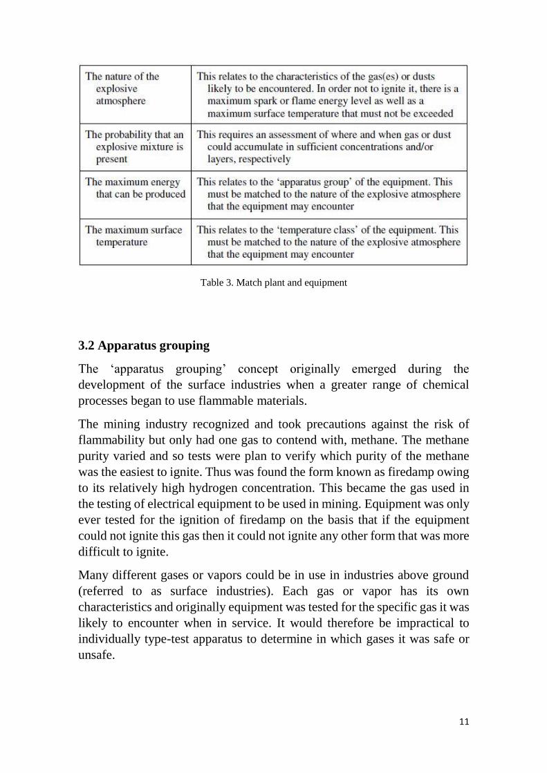
3.2 Apparatus grouping
The ‘apparatus grouping’ concept originally emerged during the
development of the surface industries when a greater range of chemical
processes began to use flammable materials.
The mining industry recognized and took precautions against the risk of
flammability but only had one gas to contend with, methane. The methane
purity varied and so tests were plan to verify which purity of the methane
was the easiest to ignite. Thus was found the form known as firedamp owing
to its relatively high hydrogen concentration. This became the gas used in
the testing of electrical equipment to be used in mining. Equipment was only
ever tested for the ignition of firedamp on the basis that if the equipment
could not ignite this gas then it could not ignite any other form that was more
difficult to ignite.
Many different gases or vapors could be in use in industries above ground
(referred to as surface industries). Each gas or vapor has its own
characteristics and originally equipment was tested for the specific gas it was
likely to encounter when in service. It would therefore be impractical to
individually type-test apparatus to determine in which gases it was safe or
unsafe.
12
Consequently, a grouping system was developed. Electrical equipment for
explosive gas atmosphere is now grouped according to the type of industry
in which they are used:
Table 4. Electrical equipment for explosive gas atmosphere
3.3 Surface temperature classification
The ignition temperature, i.e. the temperature at which an ignition could
occur, for example due to a hot surface of the apparatus, is dependent on the
type of existing gases or vapors. This ignition temperature is influenced by
several factors and is thus dependent on the stipulated testing order.
Depending on the measuring system the results can thus differ in the various
countries.
The maximum temperature of the exposed surface of electrical apparatus
must always be lower than the ignition temperature of the dust, gas or vapor
mixture, where it is to be used.
3.3.1 Group I: Electrical equipment
• With deposits of coal dust on the item of equipment … 150 °C.
• Without deposits of coal dust on the item of equipment … 450 °C.
3.3.2 Group II: Electrical equipment
In order to be able to mark and select electrical apparatus simply in regard to
its maximum surface temperature, there are several temperature classes. The
gases can be classified into the temperature classes according to their ignition
temperature, whereby the maximum surface temperature of the respective
class must be lower than the ignition temperature of the corresponding gases.
13
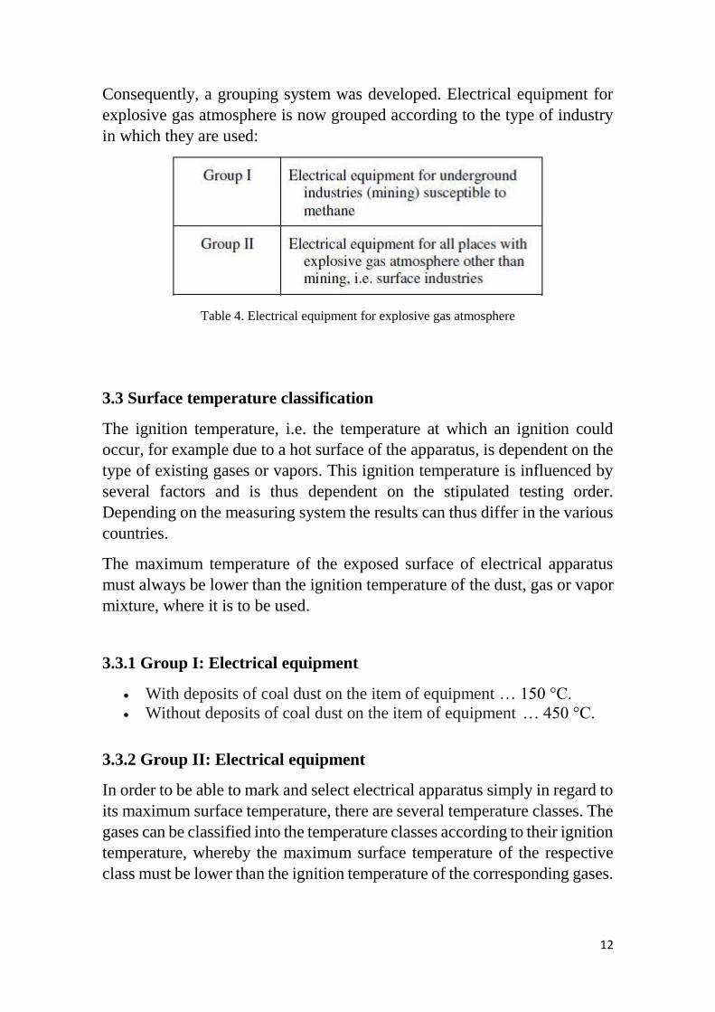
The standards define temperature classification as:
Table 5. Definition of temperature classification
The ignition temperature of gases and vapors are in no way related to the
ease of ignition by energy. Ignition temperature has to be a completely
separate consideration. The temperature classification system requires that
the maximum surface temperature of the apparatus is measured or assessed.
The value must fall in between two temperature classes ‘T ratings’ in the
following list. The lower of the two is the rating given to the apparatus.
Table 6. Temperature classification as defined by standards
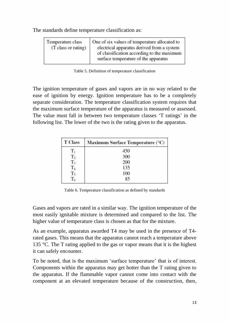
Gases and vapors are rated in a similar way. The ignition temperature of the
most easily ignitable mixture is determined and compared to the list. The
higher value of temperature class is chosen as that for the mixture.
As an example, apparatus awarded T4 may be used in the presence of T4-
rated gases. This means that the apparatus cannot reach a temperature above
135 °C. The T rating applied to the gas or vapor means that it is the highest
it can safely encounter.
To be noted, that is the maximum ‘surface temperature’ that is of interest.
Components within the apparatus may get hotter than the T rating given to
the apparatus. If the flammable vapor cannot come into contact with the
component at an elevated temperature because of the construction, then,
14
there is no need, be considered. Only the surfaces of the apparatus, which
come into contact with the vapor, are of concern.
Figure 1, gives a comparison of some common gases and vapors with a
temperature scale on which the T-rating values are placed.
Figure 2. Temperature rating system
3.4 Concepts and techniques of explosion protection
Electrical equipment can be designed, manufactured and operated in that if
they are in a hazardous area they will not contribute to causing an explosion
in several ways. Today, there are three basic approaches to providing
explosion protection to electrical circuits in hazardous location. They are as
follows:
• Explosion confinement;
• Ignition source isolation;
• Energy-release limitation.
Understanding these techniques starts with the combustion triangle.
In hazardous locations, the fuel source can be in the form of flammable
vapors, liquids, gases, combustible dust or fibers, with the oxidizer being
15
oxygen in the surrounding air. With these two ingredients present in their
most easily ignitable concentration and the introduction of sufficient
electrical or thermal energy, ignition will result. Either confining or
preventing this combustion from occurring can achieve a means of explosion
protection.
3.4.1 Explosion confinement
A common method of providing explosion protection allows the three basic
ingredients described above to coexist and potentially ignite; yet is confined
within an enclosure strong enough to withstand the explosion. All joints of
the enclosure are designed in such a manner that the resulting flame, sparks
or hot gases are sufficiently cooled before reaching the outside atmosphere.
In addition, all external surfaces must be kept below the auto ignition
temperature for the specific gas the enclosure will be exposed to.
Although a popular technique, this technology does pose many drawbacks.
Since the enclosures must contain an explosion, they are bulky, heavy and
difficult to install. All wiring entering and exiting this enclosure must also
be placed in a hardened conduit system, which requires special seals and
fittings installed according to strict regulations. This entire system must be
inspected frequently to ensure integrity. Loose bolts on the lid of an
enclosure effectively eliminate any explosion protection for the system.
3.4.2 Ignition source isolation
The second method of explosion protection is based upon the isolation of the
ignition source or energy ingredient, from the fuel/air mixture. Although
there are many acceptable methods to choose from, the most popular is
purging (internationally referred to as pressurization). This method reduces
the concentration of the fuel/air mixture initially inside the housing to an
acceptably safe level. By maintaining a high pressure inside the housing any
electrical device effectively becomes isolated from the surrounding
atmosphere.
Other ignition source isolation techniques include oil immersion, sealing,
encapsulation, sand, powder and inert gas filling.
16
3.4.3 Energy release limitation
This form of explosion protection permits the energy source to exist within
the fuel/air mixture but by design limits the amount of electrical and
thermal energy, which could be released to levels that are incapable of
causing ignition.
The most widely used forms of explosion protection, which utilize this
technique, are non-sparking and IS. While both share a common foundation,
they do differ greatly in many aspects. These differences deal mainly with
the application of safety factors. Each does have its merits, which is why it
is not uncommon to see the two techniques used together.
It should also be noted that non-sparking is not recognized outside of the
United States and Canada while IS is accepted worldwide. It is generally
regarded as the safest form of explosion protection. To date, no explosion
can be attributed to an intrinsically safe system.
By definition, IS is an explosion-protection technique applied to electrical
equipment and wiring intended for installation in hazardous locations. The
technique is based upon limiting both electrical and thermal energy to levels
which are incapable of igniting a hazardous mixture which is present in its
most easily ignitable concentration.
Intrinsic safety reduces the risk of ignition by electrical apparatus or
connecting wiring in hazardous locations. Requirements for an intrinsically
safe system do not include reducing risk of explosion related to mechanical
or electrostatic sparking, chemical action, radio waves or lightning strikes.
Protection against such events should be employed as well.
3.5 Final considerations
The certainty of protection working correctly has partly to do with the
integrity of each explosion-protection technique but is also concerned with
other installation-related topics such as fault tolerance and degree of
maintenance necessary. Safety in potentially explosive areas can only be
guaranteed by a close and effective working relationship amongst all parties
involved.
The operator is responsible for the safety of his equipment. It is his duty to
judge where there is a risk of explosion and then divide areas into zones
accordingly. He must ensure that the equipment is installed in accordance
17
with regulations and is tested before initial use. The equipment must be kept
in a fit state by regular inspection and maintenance.
The manufacturers of explosion-protected apparatus are responsible for
routine testing, certification and documentation, and are required to ensure
that each device manufactured complies with the design tested.
The installer must observe the installation requirements, and select and
install the electric apparatus correctly for its intended use.
4
Different Protection
Concepts
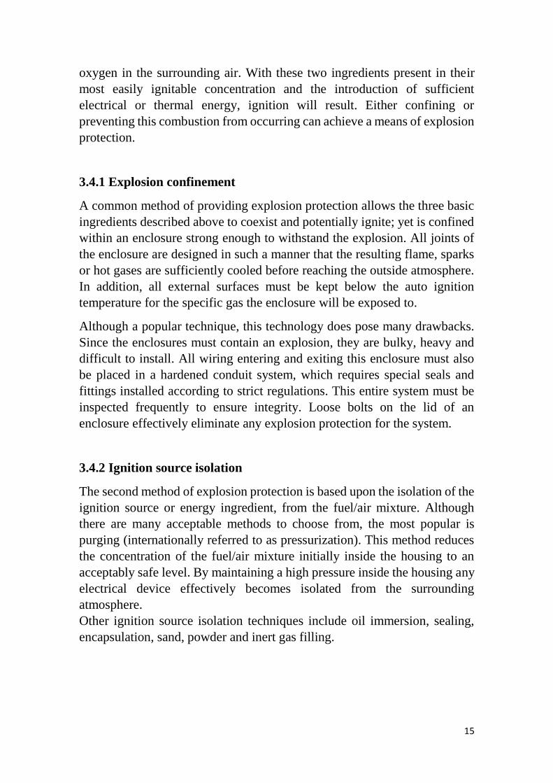
4.1 Intrinsic safety Ex i
The "intrinsic safety" protection type, as opposed to other protection types,
refers not only to individual items of equipment, but to the entire circuit. A
circuit is described as intrinsically safe if the current and voltage are limited
to such an extent that no spark or thermal effect can cause a potentially
explosive atmosphere to ignite.
Figure 3. Basic circuit diagram
18
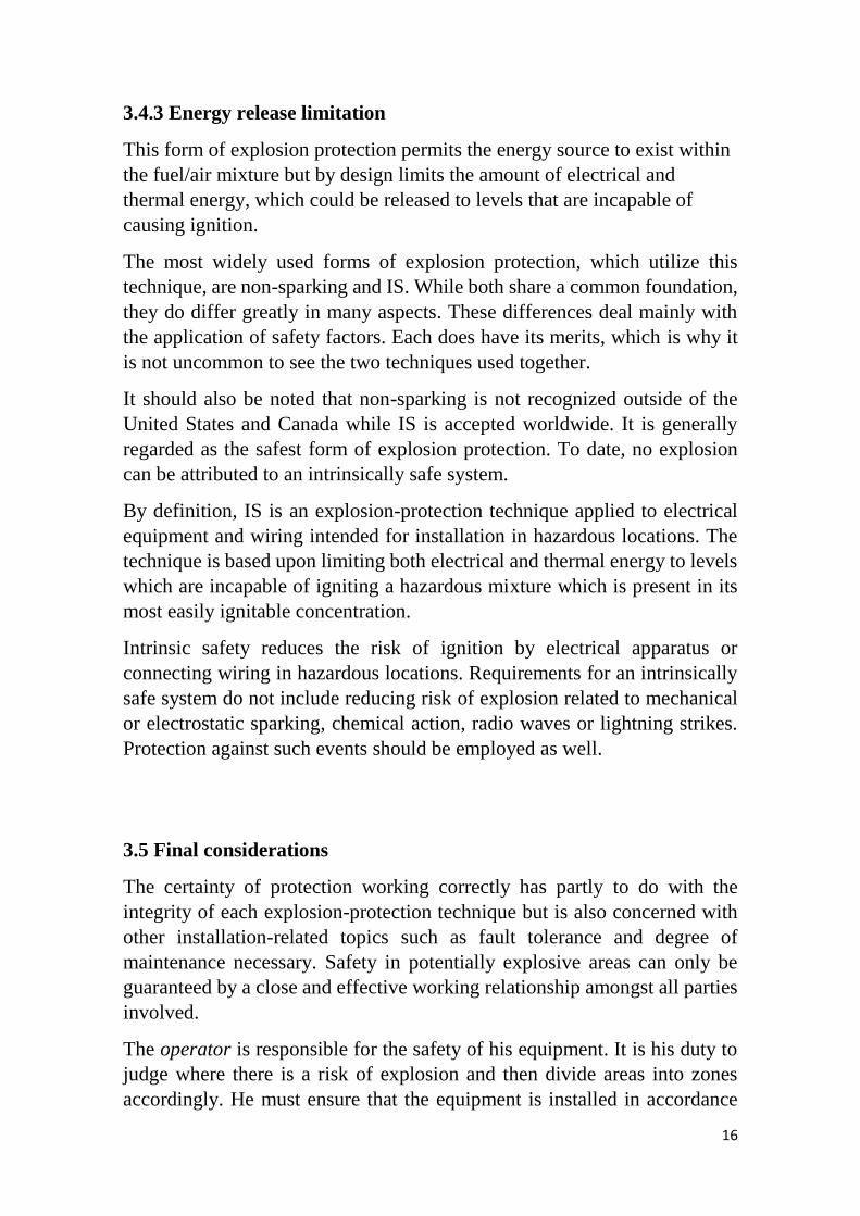
The voltage is limited in order to keep the energy of the spark below the
ignition energy of the surrounding gas. The thermal effect, i.e., excessively
hot surfaces, is prevented by limiting the current. This is also true of the
sensors connected to the intrinsically safe circuits. Energy may be stored in
the form of capacitances or inductances within the intrinsically safe circuit
and this must also be taken into account when examining said circuit.
Figure 4. Basic circuit diagram for limiting voltage and current
The Zener diode becomes conductive at a defined voltage level. This limits
the voltage Uo in the potentially explosive area. A resistor connected in
series limits the maximum current Io.
𝐼𝑚𝑎𝑥 = 𝐼𝑜 = 𝑈𝑜
𝑅
When limiting voltage and current, the following applies for the maximum
power:
𝑃𝑜 = 𝑈𝑜2
4𝑅
The maximum permissible values are determined by the ignition limit curves
laid down in standard EN 60079-11.
The ignition limit curves were determined using a spark tester, as described
in Annex B of EN 60079-11.
The ignition limit curves contain specifications for gas groups I and II.
19
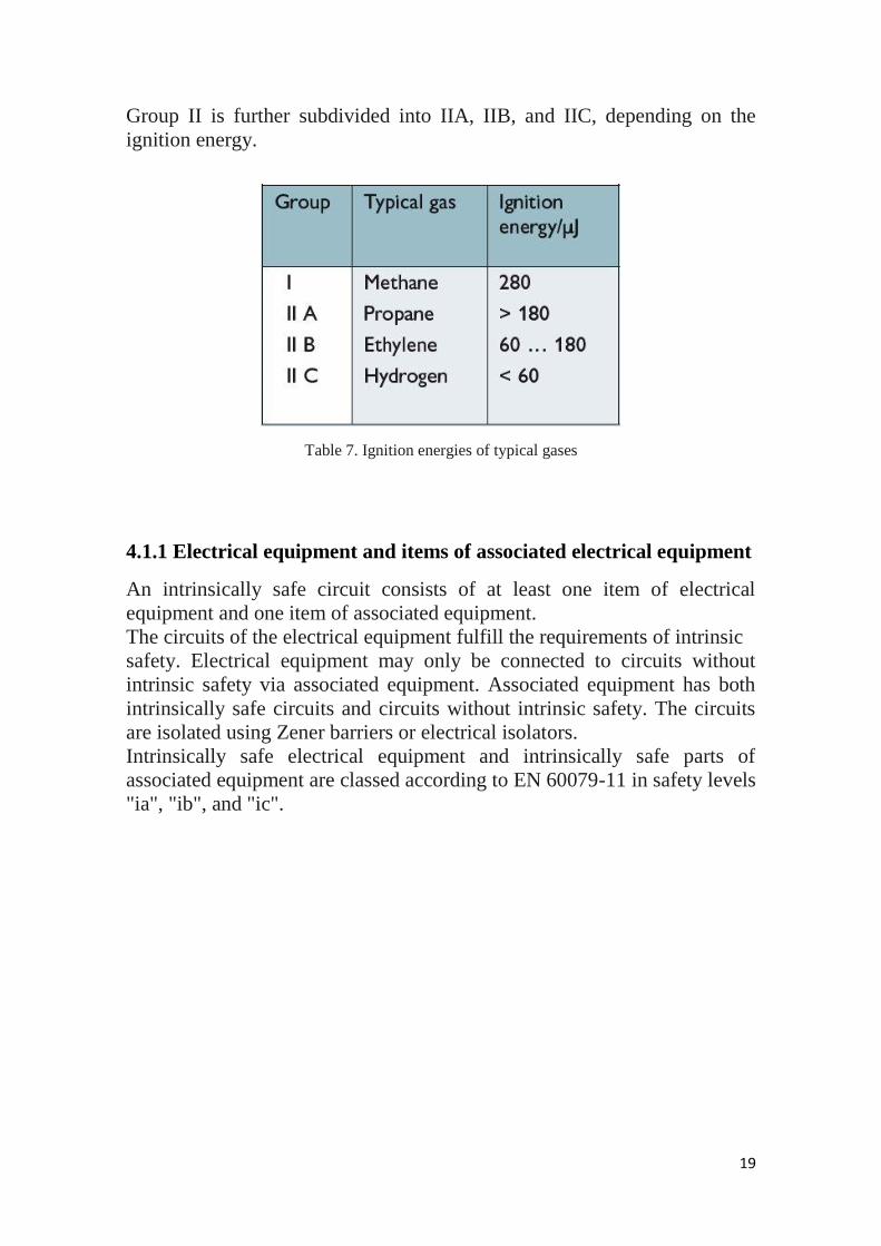
Group II is further subdivided into IIA, IIB, and IIC, depending on the
ignition energy.
Table 7. Ignition energies of typical gases
4.1.1 Electrical equipment and items of associated electrical equipment
An intrinsically safe circuit consists of at least one item of electrical
equipment and one item of associated equipment.
The circuits of the electrical equipment fulfill the requirements of intrinsic
safety. Electrical equipment may only be connected to circuits without
intrinsic safety via associated equipment. Associated equipment has both
intrinsically safe circuits and circuits without intrinsic safety. The circuits
are isolated using Zener barriers or electrical isolators.
Intrinsically safe electrical equipment and intrinsically safe parts of
associated equipment are classed according to EN 60079-11 in safety levels
"ia", "ib", and "ic".

20
Table 8. Safety level according to EN 60079-11
Safety level "ia", "ib" or "ic" defines whether protection is maintained with
two or one faults in the protective circuit, or whether no protection is
provided in the event of a fault.
Intrinsic safety is based on monitoring faults in order to rule out the danger
of explosion. This does not, however, provide any conclusions as to
operational reliability. This means that a total functional failure of the item
of equipment can be permissible from the point of view of explosion
protection.
Electrical equipment can be used right up to Zone 0 in accordance with the
safety level. Associated equipment is installed in the safe area. Only the
intrinsically safe circuits are routed into the potentially explosive area,
according to the safety level.
Associated equipment can always be designed in a different protection type
in order for it to be installed in Zone 2 or maybe even in Zone 1.
21
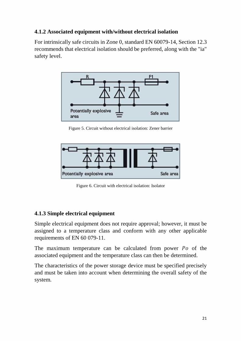
4.1.2 Associated equipment with/without electrical isolation
For intrinsically safe circuits in Zone 0, standard EN 60079-14, Section 12.3
recommends that electrical isolation should be preferred, along with the "ia"
safety level.
Figure 5. Circuit without electrical isolation: Zener barrier
Figure 6. Circuit with electrical isolation: Isolator
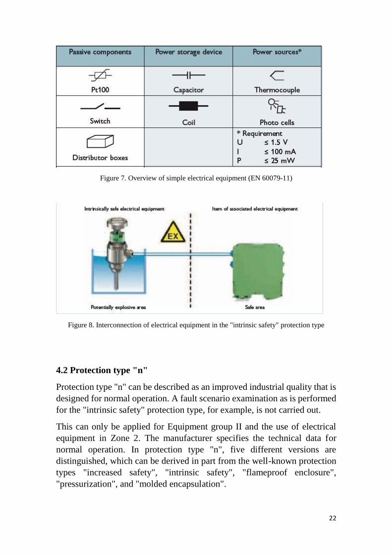
4.1.3 Simple electrical equipment
Simple electrical equipment does not require approval; however, it must be
assigned to a temperature class and conform with any other applicable
requirements of EN 60 079-11.
The maximum temperature can be calculated from power 𝑃𝑜 of the
associated equipment and the temperature class can then be determined.
The characteristics of the power storage device must be specified precisely
and must be taken into account when determining the overall safety of the
system.
22
Figure 7. Overview of simple electrical equipment (EN 60079-11)
Figure 8. Interconnection of electrical equipment in the "intrinsic safety" protection type
4.2 Protection type "n"
Protection type "n" can be described as an improved industrial quality that is
designed for normal operation. A fault scenario examination as is performed
for the "intrinsic safety" protection type, for example, is not carried out.
This can only be applied for Equipment group II and the use of electrical
equipment in Zone 2. The manufacturer specifies the technical data for
normal operation. In protection type "n", five different versions are
distinguished, which can be derived in part from the well-known protection
types "increased safety", "intrinsic safety", "flameproof enclosure",
"pressurization", and "molded encapsulation".
23
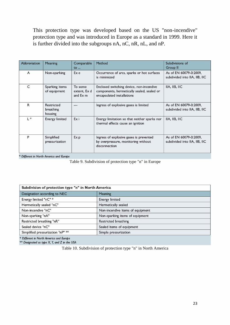
This protection type was developed based on the US "non-incendive"
protection type and was introduced in Europe as a standard in 1999. Here it
is further divided into the subgroups nA, nC, nR, nL, and nP.
Table 9. Subdivision of protection type "n" in Europe
Table 10. Subdivision of protection type "n" in North America
24
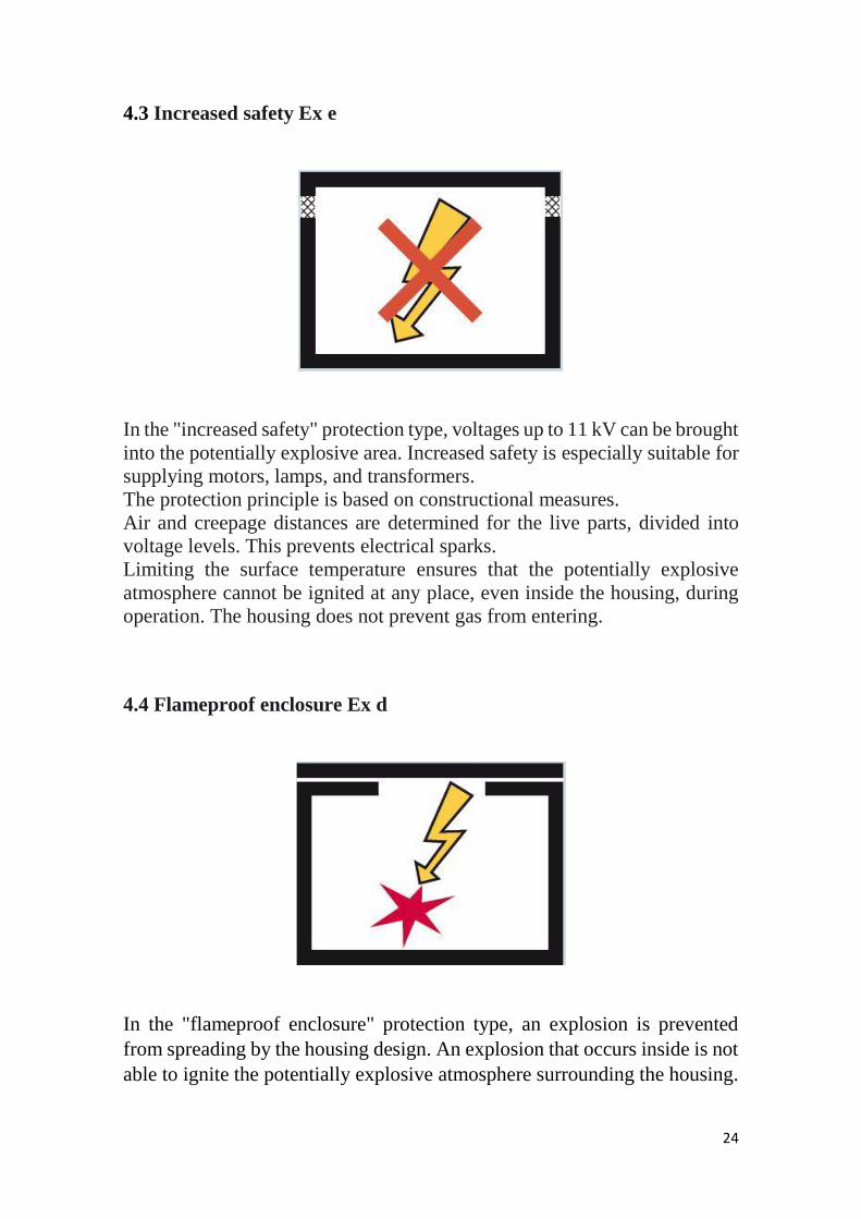
4.3 Increased safety Ex e
In the "increased safety" protection type, voltages up to 11 kV can be brought
into the potentially explosive area. Increased safety is especially suitable for
supplying motors, lamps, and transformers.
The protection principle is based on constructional measures.
Air and creepage distances are determined for the live parts, divided into
voltage levels. This prevents electrical sparks.
Limiting the surface temperature ensures that the potentially explosive
atmosphere cannot be ignited at any place, even inside the housing, during
operation. The housing does not prevent gas from entering.
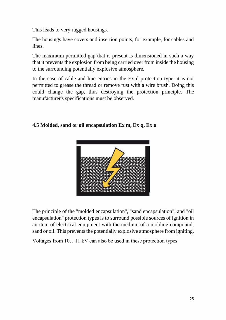
4.4 Flameproof enclosure Ex d
In the "flameproof enclosure" protection type, an explosion is prevented
from spreading by the housing design. An explosion that occurs inside is not
able to ignite the potentially explosive atmosphere surrounding the housing.
25
This leads to very rugged housings.
The housings have covers and insertion points, for example, for cables and
lines.
The maximum permitted gap that is present is dimensioned in such a way
that it prevents the explosion from being carried over from inside the housing
to the surrounding potentially explosive atmosphere.
In the case of cable and line entries in the Ex d protection type, it is not
permitted to grease the thread or remove rust with a wire brush. Doing this
could change the gap, thus destroying the protection principle. The
manufacturer's specifications must be observed.
4.5 Molded, sand or oil encapsulation Ex m, Ex q, Ex o
The principle of the "molded encapsulation", "sand encapsulation", and "oil
encapsulation" protection types is to surround possible sources of ignition in
an item of electrical equipment with the medium of a molding compound,
sand or oil. This prevents the potentially explosive atmosphere from igniting.
Voltages from 10…11 kV can also be used in these protection types.
26
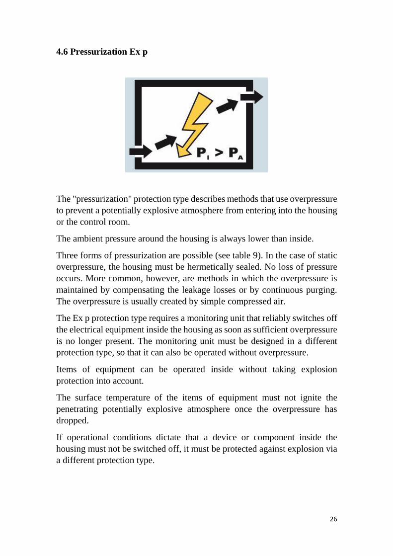
4.6 Pressurization Ex p
The "pressurization" protection type describes methods that use overpressure
to prevent a potentially explosive atmosphere from entering into the housing
or the control room.
The ambient pressure around the housing is always lower than inside.
Three forms of pressurization are possible (see table 9). In the case of static
overpressure, the housing must be hermetically sealed. No loss of pressure
occurs. More common, however, are methods in which the overpressure is
maintained by compensating the leakage losses or by continuous purging.
The overpressure is usually created by simple compressed air.
The Ex p protection type requires a monitoring unit that reliably switches off
the electrical equipment inside the housing as soon as sufficient overpressure
is no longer present. The monitoring unit must be designed in a different
protection type, so that it can also be operated without overpressure.
Items of equipment can be operated inside without taking explosion
protection into account.
The surface temperature of the items of equipment must not ignite the
penetrating potentially explosive atmosphere once the overpressure has
dropped.
If operational conditions dictate that a device or component inside the
housing must not be switched off, it must be protected against explosion via
a different protection type.
27
Table 11. Possibilities of pressurization
5
Safe Working Practice
Having a project designed and installed as per the regulations it is of utmost
importance to give adequate attention to the adoption of safe working
methods and practices that will ensure:
MISHAP PREVENTION AND LOSS PREVENTION OF MEN AND
MATERIAL
Most of who works with electricity take risks. Mishaps or injuries usually
result from an unclear understanding of a risk or danger.
It is important to look at some of the more obvious practices that any
electrical technician is supposed to follow in terms of:
• Safety
• Looking out for danger signals
• Inspection and maintenance requirements
• Maintenance and safe practices
28
• Safe methods of insulation testing and requirements for hazardous
area
• Safe methods of earth integrity checking and the specific requirements
for a hazardous area
• Safe practices after fire and electrical shock.
5.1 Safety observations
Working safely is the most important thing you can do. Of course, there are
more precautions, but these are some you should definitely care about. The
keyword here is think.
• Never work alone;
• Never receive an intentional shock (e.g. by testing);
• Only work on, operate or adjust equipment if you are authorized;
• Do not work on energized equipment unless absolutely necessary;
• Keep loose tools, metal parts and liquids from the electrical
equipment. Never use steel wool or emery cloth on electric and
electronic circuits;
• Never attempt to repair energized circuits except in an emergency;
• As a general rule, never measure voltages in excess of 300 V while
holding the meter wire or probe;
• Use only one hand when operating circuit breakers or switches;
• Use proper tag-out procedures for regular and preventive
maintenance;
• Be cautious when working in voids or unvented spaces;
• Beware of the dangers of working aloft. Never attempt to stop a
rotating antenna manually;
• Keep protective closures, fuse panels and circuit breaker boxes closed
unless you are actually working on them;
• Never bypass an interlock unless you are authorized to do so by the
authorized persons, and then properly tag the bypass.
Warning signs
They have been placed for your protection. To disregard them is to invite
personal injury as well as possible damage to equipment. Switches and
29
receptacles with a temporary warning tag, indicating work is being
performed, are not to be touched.
Working near electrical equipment
When work must be performed in the immediate vicinity of electrical
equipment, check with the technician responsible for the maintenance of the
equipment so you can avoid any potential hazard of which you may not be
immediately aware.
Authorized personnel only
Because of the danger of fire, damage to equipment and injury to personnel,
only authorized persons shall do maintenance work on electrical equipment.
Keep your hands off all equipment, which you have not been specifically
authorized to handle. Particularly stay clear of electrical equipment opened
for inspection, testing or servicing.
Circuit breakers and fuses
Covers for all fuse boxes, junction boxes, switch boxes and wiring
accessories should be kept closed. Any cover, which is not closed or is
missing, should be reported to the technician responsible for its maintenance.
Failure to do so may result in injury to personnel or damage to equipment in
the event accidental contact is made with exposed live circuits.
5.2 Need for inspection and maintenance
‘Loss prevention’ is one of the main objectives of any ongoing enterprise, it
is needless to emphasize that this can be only achieved if all the apparatus,
equipment and systems for hazardous area are designed, selected and
installed with great care. The equipment must also be maintained as close as
possible to the state it was when it was new.
Electrical installations, which comply with standards and regulations, or with
other statutory documents dealing with the same subject, possess features
specially designed to render them suitable for operation in hazardous areas.
It is essential for reasons of safety in those areas that throughout the life of
30
such installations the integrity of those special features is preserved. They
therefore require systematic inspection and if necessary, maintenance both
initially and at regular periodic intervals thereafter.
The above makes it imperative that a formal and exhaustive documentation
procedure should be put in place. This should also cover the requisite
procedures for inspection, testing and certification wherever necessary for
the following:
• Commissioning and test verification
• Operation
• Storage of flammable material
• Maintenance schedule
• Authorized modifications
• Overhaul and repair.
It should be noted that the required certificate/documentation needs to be
issued for the maintenance schedule and authorized modifications, and these
should be included in a hazardous area verification dossier.
Normal overhaul and other activities need also to be suitably documented.
The facility in charge shall nominate a person (or persons) having the
appropriate knowledge and experience of hazardous area installations to be
responsible for establishing and implementing a system of inspection and
maintenance, which shall keep the plant operating safely.

31
6
Bibliography
https://www.youtube.com/watch?v=4cYYzsBZDLE
https://www.youtube.com/watch?v=prXtKchQyPE
https://www.youtube.com/watch?v=S9gE8mbpjGY
https://www.youtube.com/watch?v=jm1L4b_XktM
https://www.youtube.com/watch?v=V7mYThsVvt8
https://www.youtube.com/watch?v=ymvfoNbSpXY
https://en.wikipedia.org/wiki/Electrical_equipment_in_hazardous_areas
https://www.bartec.de/en/downloads/safety-academy/ex-protection.pdf
http://www.iceweb.com.au/Ex-
web/Hazardous%20Areas%20Tech%20Guide.pdf
http://www.sourceiex.com/Catalogs/Chapter%2012%20EX%20Protection
%20Techniques.pdf
https://www.phoenixcontact.com/assets/downloads_ed/global/web_dwl_tec
hnical_info/5149416_EN_HQ_LR.pdf
http://www.dustexplosion.info/atex%20zones%20for%20dust.htm
http://www.hse.gov.uk/fireandexplosion/zoning.pdf
https://ec.europa.eu/growth/single-market/european-standards/harmonised-
standards/equipment-explosive-atmosphere_pt
Bottrill, Geoffrey; Cheyne, Derek; Vijayaraghavan, G. Practical Electrical
Equipment and Installations in Hazardous Areas. Elsevier, 2005.

![[Guía formativa del EIR1] · - Consulta de enfermería: educación en salud individual-grupal, actividades de prevención, consulta de demanda, atención al agudo: triaje, cuidados](https://img.pdfslide.net/doc/110x75/5bc3cd6809d3f248318d5df8/guia-formativa-del-eir1-consulta-de-enfermeria-educacion-en-salud-individual-grupal.jpg)