Embed Size (px)
DESCRIPTION
Steel Cable Dampers
Citation preview
The 14th
World Conference on Earthquake Engineering October 12-17, 2008, Beijing, China STUDY OF THE EFFECTIVENESS OF STEEL CABLE DAMPERS FOR THE
SEISMIC PROTECTION OF ELECTRICAL EQUIPMENT
F. Paolacci1 and R. Giannini
2
1 Assistant Professor, Department of Structures, University of Roma Tre, Rome. Italy
2 Full Professor, Department of Structures, University of Roma Tre, Rome. Italy
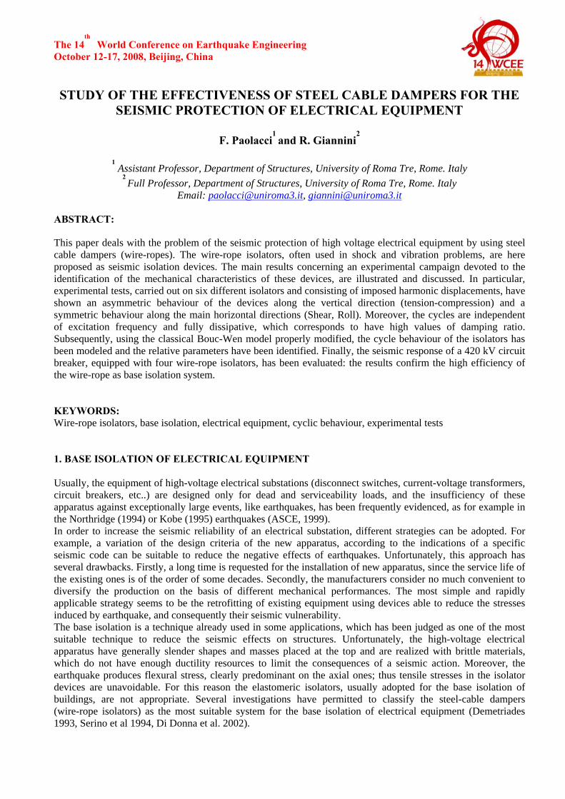
Email: [email protected], [email protected] ABSTRACT: This paper deals with the problem of the seismic protection of high voltage electrical equipment by using steel cable dampers (wire-ropes). The wire-rope isolators, often used in shock and vibration problems, are here proposed as seismic isolation devices. The main results concerning an experimental campaign devoted to the identification of the mechanical characteristics of these devices, are illustrated and discussed. In particular, experimental tests, carried out on six different isolators and consisting of imposed harmonic displacements, have shown an asymmetric behaviour of the devices along the vertical direction (tension-compression) and a symmetric behaviour along the main horizontal directions (Shear, Roll). Moreover, the cycles are independent of excitation frequency and fully dissipative, which corresponds to have high values of damping ratio. Subsequently, using the classical Bouc-Wen model properly modified, the cycle behaviour of the isolators has been modeled and the relative parameters have been identified. Finally, the seismic response of a 420 kV circuit breaker, equipped with four wire-rope isolators, has been evaluated: the results confirm the high efficiency of the wire-rope as base isolation system. KEYWORDS: Wire-rope isolators, base isolation, electrical equipment, cyclic behaviour, experimental tests 1. BASE ISOLATION OF ELECTRICAL EQUIPMENT Usually, the equipment of high-voltage electrical substations (disconnect switches, current-voltage transformers, circuit breakers, etc..) are designed only for dead and serviceability loads, and the insufficiency of these apparatus against exceptionally large events, like earthquakes, has been frequently evidenced, as for example in the Northridge (1994) or Kobe (1995) earthquakes (ASCE, 1999). In order to increase the seismic reliability of an electrical substation, different strategies can be adopted. For example, a variation of the design criteria of the new apparatus, according to the indications of a specific seismic code can be suitable to reduce the negative effects of earthquakes. Unfortunately, this approach has several drawbacks. Firstly, a long time is requested for the installation of new apparatus, since the service life of the existing ones is of the order of some decades. Secondly, the manufacturers consider no much convenient to diversify the production on the basis of different mechanical performances. The most simple and rapidly applicable strategy seems to be the retrofitting of existing equipment using devices able to reduce the stresses induced by earthquake, and consequently their seismic vulnerability. The base isolation is a technique already used in some applications, which has been judged as one of the most suitable technique to reduce the seismic effects on structures. Unfortunately, the high-voltage electrical apparatus have generally slender shapes and masses placed at the top and are realized with brittle materials, which do not have enough ductility resources to limit the consequences of a seismic action. Moreover, the earthquake produces flexural stress, clearly predominant on the axial ones; thus tensile stresses in the isolator devices are unavoidable. For this reason the elastomeric isolators, usually adopted for the base isolation of buildings, are not appropriate. Several investigations have permitted to classify the steel-cable dampers (wire-rope isolators) as the most suitable system for the base isolation of electrical equipment (Demetriades 1993, Serino et al 1994, Di Donna et al. 2002).
The 14th
World Conference on Earthquake Engineering October 12-17, 2008, Beijing, China
L
φ
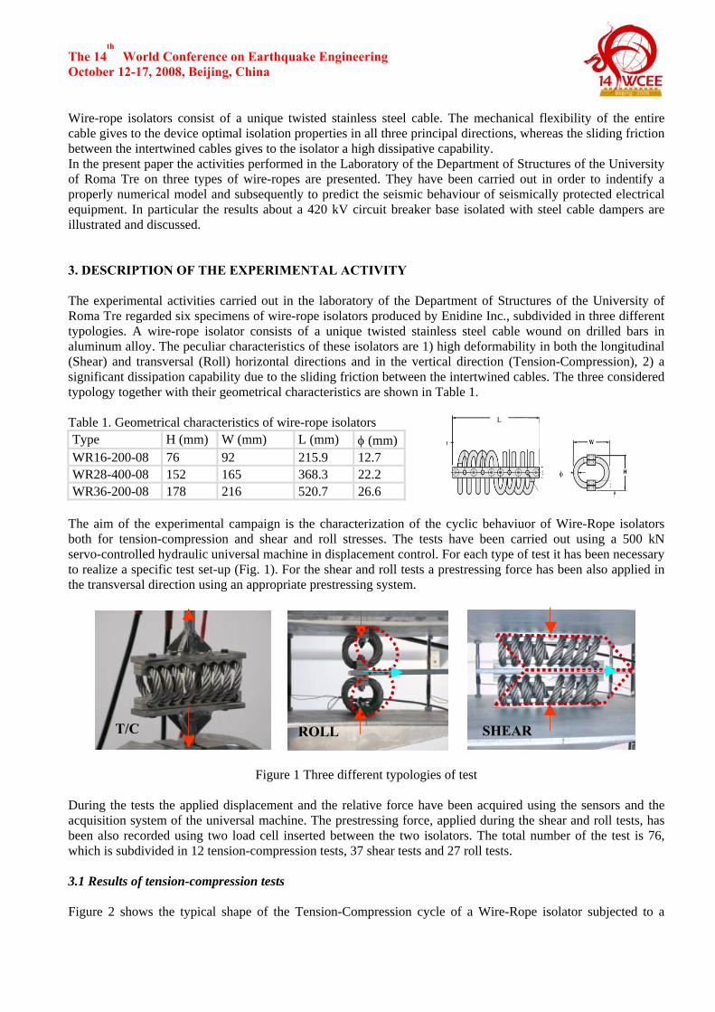
Wire-rope isolators consist of a unique twisted stainless steel cable. The mechanical flexibility of the entire cable gives to the device optimal isolation properties in all three principal directions, whereas the sliding friction between the intertwined cables gives to the isolator a high dissipative capability. In the present paper the activities performed in the Laboratory of the Department of Structures of the University of Roma Tre on three types of wire-ropes are presented. They have been carried out in order to indentify a properly numerical model and subsequently to predict the seismic behaviour of seismically protected electrical equipment. In particular the results about a 420 kV circuit breaker base isolated with steel cable dampers are illustrated and discussed. 3. DESCRIPTION OF THE EXPERIMENTAL ACTIVITY The experimental activities carried out in the laboratory of the Department of Structures of the University of Roma Tre regarded six specimens of wire-rope isolators produced by Enidine Inc., subdivided in three different typologies. A wire-rope isolator consists of a unique twisted stainless steel cable wound on drilled bars in aluminum alloy. The peculiar characteristics of these isolators are 1) high deformability in both the longitudinal (Shear) and transversal (Roll) horizontal directions and in the vertical direction (Tension-Compression), 2) a significant dissipation capability due to the sliding friction between the intertwined cables. The three considered typology together with their geometrical characteristics are shown in Table 1. Table 1. Geometrical characteristics of wire-rope isolators Type H (mm) W (mm) L (mm) φ (mm)WR16-200-08 76 92 215.9 12.7 WR28-400-08 152 165 368.3 22.2 WR36-200-08 178 216 520.7 26.6
The aim of the experimental campaign is the characterization of the cyclic behaviuor of Wire-Rope isolators both for tension-compression and shear and roll stresses. The tests have been carried out using a 500 kN servo-controlled hydraulic universal machine in displacement control. For each type of test it has been necessary to realize a specific test set-up (Fig. 1). For the shear and roll tests a prestressing force has been also applied in the transversal direction using an appropriate prestressing system.
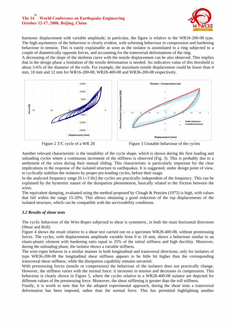
Figure 1 Three different typologies of test During the tests the applied displacement and the relative force have been acquired using the sensors and the acquisition system of the universal machine. The prestressing force, applied during the shear and roll tests, has been also recorded using two load cell inserted between the two isolators. The total number of the test is 76, which is subdivided in 12 tension-compression tests, 37 shear tests and 27 roll tests. 3.1 Results of tension-compression tests Figure 2 shows the typical shape of the Tension-Compression cycle of a Wire-Rope isolator subjected to a
T/C ROLL SHEAR
The 14th
World Conference on Earthquake Engineering October 12-17, 2008, Beijing, China harmonic displacement with variable amplitude; in particular, the figure is relative to the WR16-200-08 type. The high asymmetry of the behaviour is clearly evident, with softening behaviour in compression and hardening behaviour in tension. This is easily explainable as soon as the isolator is assimilated to a ring subjected to a couple of diametrically opposite forces, and accounting for the transversal deformations of the ring. A decreasing of the slope of the skeleton curve with the tensile displacement can be also observed. This implies that in the design phase a limitation of the tensile deformation is needed. An indicative value of this threshold is about 5-6% of the diameter of the coils. For example, the maximum tensile displacement could be lower than 4 mm, 10 mm and 12 mm for WR16-200-08, WR28-400-08 and WR36-200-08 respectively.
-15000
-10000
-5000
0
5000
10000
15000
-15 -10 -5 0 5
Spostamento ( mm )
Forz
a ( K
N )
Displacement (mm)
Force(N)
Prove di Compressione - Trazione
-4
-3
-2
-1
0
1
2
3
4
-1 -0,8 -0,6 -0,4 -0,2 0 0,2 0,4 0,6 0,8 1
Spostamento ( mm )
Forz
a C
ompr
essi
one
- Tra
zion
e ( K
N )
Comportamento instabileComportamento stabile
Displacement (mm)
Force(Ten
sion
‐Com
pression
) (kN
)
Tension – Compression test
Stable behaviourUnstable behaviour
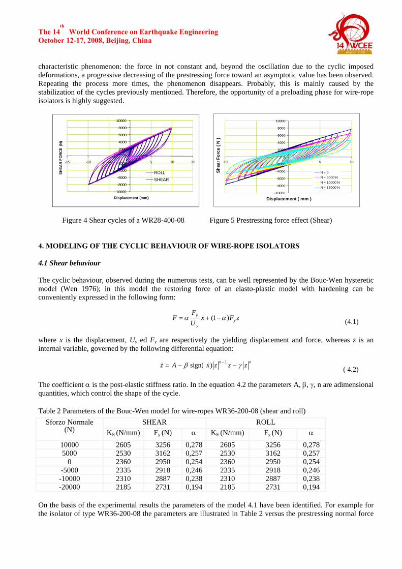
Figure 2 T/C cycle of a WR 28 Figure 3 Unstable behaviour of the cycles Another relevant characteristic is the instability of the cycle shape, which is shown during the first loading and unloading cycles where a continuous increment of the stiffness is observed (Fig. 3). This is probably due to a settlement of the wires during their mutual sliding. This characteristic is particularly important for the clear implications in the response of the isolated structure to earthquakes. It is suggested, under design point of view, to cyclically stabilize the isolators by proper pre-loading cycles, before their usage. In the analyzed frequency range [0.1÷3 Hz] the cycles are practically independent of the frequency. This can be explained by the hysteretic nature of the dissipation phenomenon, basically related to the friction between the wires. The equivalent damping, evaluated using the method proposed by Clough & Penzien (1975) is high, with values that fall within the range 15-20%. This allows obtaining a good reduction of the top displacements of the isolated structure, which can be compatible with the serviceability conditions. 3.2 Results of shear tests The cyclic behaviour of the Wire-Ropes subjected to shear is symmetric, in both the main horizontal directions (Shear and Roll). Figure 4 shows the result relative to a shear test carried out on a specimen WR28-400-08, without prestressing forces. The cycles, with displacements amplitude variable from 0 to 10 mm, shows a behaviour similar to an elasto-plastic element with hardening ratio equal to 25% of the initial stiffness and high ductility. Moreover, during the unloading phase, the isolator shows a variable stiffness. The wire-ropes behaves in a similar manner in both longitudinal and transversal directions; only for isolators of type WR36-200-08 the longitudinal shear stiffness appears to be little bit higher than the corresponding transversal shear stiffness, while the dissipation capability remains unvaried. With prestressing forces (tensile or compression) the behaviour of the isolators does not practically change. However, the stiffness varies with the normal force: it increases in tension and decreases in compression. This behaviour is clearly shown in Figure 5, where the cycles relative to a WR28-400-08 isolator are depicted for different values of the prestressing force. Moreover, the shear stiffening is greater than the roll stiffness. Finally, it is worth to note that for the adopted experimental approach, during the shear tests a transversal deformation has been imposed, rather than the normal force. This has permitted highlighting another
The 14th
World Conference on Earthquake Engineering October 12-17, 2008, Beijing, China characteristic phenomenon: the force in not constant and, beyond the oscillation due to the cyclic imposed deformations, a progressive decreasing of the prestressing force toward an asymptotic value has been observed. Repeating the process more times, the phenomenon disappears. Probably, this is mainly caused by the stabilization of the cycles previously mentioned. Therefore, the opportunity of a preloading phase for wire-rope isolators is highly suggested.
-10000
-8000
-6000
-4000
-2000
0
2000
4000
6000
8000
10000
-15 -10 -5 0 5 10 15
SHEA
R FO
RCE
(N)
Displacement (mm)
ROLLSHEAR
-10000
-8000
-6000
-4000
-2000
0
2000
4000
6000
8000
10000
-10 -5 0 5 10
Shea
r For
ce (
N )
Displacement ( mm )
N = 0N = 5000 NN = 10000 NN = 15000 N
Figure 4 Shear cycles of a WR28-400-08 Figure 5 Prestressing force effect (Shear) 4. MODELING OF THE CYCLIC BEHAVIOUR OF WIRE-ROPE ISOLATORS 4.1 Shear behaviour The cyclic behaviour, observed during the numerous tests, can be well represented by the Bouc-Wen hysteretic model (Wen 1976); in this model the restoring force of an elasto-plastic model with hardening can be conveniently expressed in the following form:
zFxUF
F yy
y )1( αα −+= (4.1) where x is the displacement, Uy ed Fy are respectively the yielding displacement and force, whereas z is an internal variable, governed by the following differential equation:
nn zzzxAz γβ −−= −1)sign( &&
( 4.2) The coefficient α is the post-elastic stiffness ratio. In the equation 4.2 the parameters A, β, γ, n are adimensional quantities, which control the shape of the cycle.
Table 2 Parameters of the Bouc-Wen model for wire-ropes WR36-200-08 (shear and roll) Sforzo Normale
(N) SHEAR ROLL
KE (N/mm) Fy (N) α KE (N/mm) Fy (N) α 10000 2605 3256 0,278 2605 3256 0,278 5000 2530 3162 0,257 2530 3162 0,257
0 2360 2950 0,254 2360 2950 0,254 -5000 2335 2918 0,246 2335 2918 0,246
-10000 2310 2887 0,238 2310 2887 0,238 -20000 2185 2731 0,194 2185 2731 0,194
On the basis of the experimental results the parameters of the model 4.1 have been identified. For example for the isolator of type WR36-200-08 the parameters are illustrated in Table 2 versus the prestressing normal force
The 14th
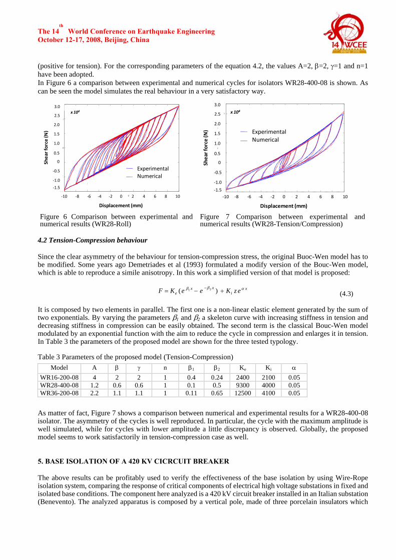
World Conference on Earthquake Engineering October 12-17, 2008, Beijing, China (positive for tension). For the corresponding parameters of the equation 4.2, the values A=2, β=2, γ=1 and n=1 have been adopted. In Figure 6 a comparison between experimental and numerical cycles for isolators WR28-400-08 is shown. As can be seen the model simulates the real behaviour in a very satisfactory way.
-10 -8 -6 -4 -2 0 2 4 6 8 10-1.5
-1
-0.5
0
0.5
1
1.5 x 10
SPOSTAMENTO ( MM )
FOR
ZA D
I TAG
LIO
RO
LL (
N )
CICLI SPERIMENTALI CICLI SIMULATI
SOLLECITAZIONE DI ROLL SENZA SFORZO DI COMPRESSIONE
WR 36 - 200 - 08
‐4‐10 ‐8 ‐6
Displacement (mm)
‐2 0 2 4 6 8 10
ExperimentalNumerical
Shearforce
(N)
‐1.5
‐1.0
‐0.5
0
0.5
1.0
1.5
2.0
2.5
3.0x 10⁴
-10 -8 -6 -4 -2 0 2 4 6 8 10-1.5
-1
-0.5
0
0.5
1
1.5
2
2.5
3
CICLO SPERIMENTALECICLO SIMULATO
SPOSTAMENTO ( mm )
FOR
ZA D
I CO
MPR
ESSI
ONE
- TR
AZIO
NE
( N )
Shearforce
(N)
‐4
ExperimentalNumerical
‐10 ‐8 ‐6
Displacement (mm)
‐2 0 2 4 6 8 10‐1.5
‐1.0
‐0.5
0
0.5
1.0
1.5
2.0
2.5
3.0
x 104
Figure 6 Comparison between experimental and numerical results (WR28-Roll)
Figure 7 Comparison between experimental and numerical results (WR28-Tension/Compression)
4.2 Tension-Compression behaviour Since the clear asymmetry of the behaviour for tension-compression stress, the original Buoc-Wen model has to be modified. Some years ago Demetriades et al (1993) formulated a modify version of the Bouc-Wen model, which is able to reproduce a simile anisotropy. In this work a simplified version of that model is proposed:
x
ixx
e ezKeeKF αββ +−= − )( 21
(4.3)
It is composed by two elements in parallel. The first one is a non-linear elastic element generated by the sum of two exponentials. By varying the parameters β1 and β2 a skeleton curve with increasing stiffness in tension and decreasing stiffness in compression can be easily obtained. The second term is the classical Bouc-Wen model modulated by an exponential function with the aim to reduce the cycle in compression and enlarges it in tension. In Table 3 the parameters of the proposed model are shown for the three tested typology.
Table 3 Parameters of the proposed model (Tension-Compression)
Model A β γ n β1 β2 Ke Ki α WR16-200-08 4 2 2 1 0.4 0.24 2400 2100 0.05 WR28-400-08 1.2 0.6 0.6 1 0.1 0.5 9300 4000 0.05 WR36-200-08 2.2 1.1 1.1 1 0.11 0.65 12500 4100 0.05
As matter of fact, Figure 7 shows a comparison between numerical and experimental results for a WR28-400-08 isolator. The asymmetry of the cycles is well reproduced. In particular, the cycle with the maximum amplitude is well simulated, while for cycles with lower amplitude a little discrepancy is observed. Globally, the proposed model seems to work satisfactorily in tension-compression case as well. 5. BASE ISOLATION OF A 420 KV CICRCUIT BREAKER The above results can be profitably used to verify the effectiveness of the base isolation by using Wire-Rope isolation system, comparing the response of critical components of electrical high voltage substations in fixed and isolated base conditions. The component here analyzed is a 420 kV circuit breaker installed in an Italian substation (Benevento). The analyzed apparatus is composed by a vertical pole, made of three porcelain insulators which
The 14th
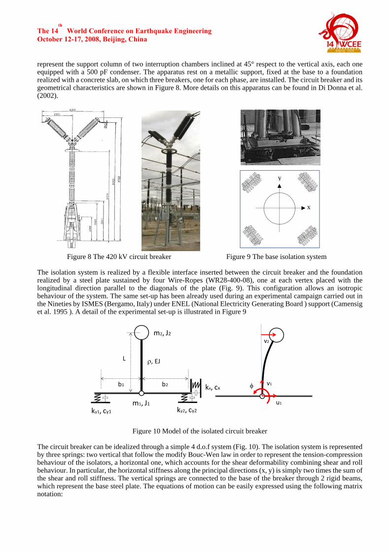
World Conference on Earthquake Engineering October 12-17, 2008, Beijing, China represent the support column of two interruption chambers inclined at 45° respect to the vertical axis, each one equipped with a 500 pF condenser. The apparatus rest on a metallic support, fixed at the base to a foundation realized with a concrete slab, on which three breakers, one for each phase, are installed. The circuit breaker and its geometrical characteristics are shown in Figure 8. More details on this apparatus can be found in Di Donna et al. (2002).
Figure 8 The 420 kV circuit breaker Figure 9 The base isolation system The isolation system is realized by a flexible interface inserted between the circuit breaker and the foundation realized by a steel plate sustained by four Wire-Ropes (WR28-400-08), one at each vertex placed with the longitudinal direction parallel to the diagonals of the plate (Fig. 9). This configuration allows an isotropic behaviour of the system. The same set-up has been already used during an experimental campaign carried out in the Nineties by ISMES (Bergamo, Italy) under ENEL (National Electricity Generating Board ) support (Camensig et al. 1995 ). A detail of the experimental set-up is illustrated in Figure 9
m2, J2
m1, J1ky1, cy1 ky2, cy2
kx, cx
v2
v1
u1
φb1 b2
L ρ, EJ
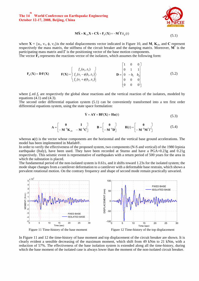
Figure 10 Model of the isolated circuit breaker The circuit breaker can be idealized through a simple 4 d.o.f system (Fig. 10). The isolation system is represented by three springs: two vertical that follow the modify Bouc-Wen law in order to represent the tension-compression behaviour of the isolators, a horizontal one, which accounts for the shear deformability combining shear and roll behaviour. In particular, the horizontal stiffness along the principal directions (x, y) is simply two times the sum of the shear and roll stiffness. The vertical springs are connected to the base of the breaker through 2 rigid beams, which represent the base steel plate. The equations of motion can be easily expressed using the following matrix notation:
y
x
The 14th
World Conference on Earthquake Engineering October 12-17, 2008, Beijing, China
)()( * tugdcb &&&&& ΓMXFXCXKXM −=+++ (5.1)
where X = {u1, v1, φ, v2}is the nodal displacements vector indicated in Figure 10, and M, Kcb, and C represent respectively the mass matrix, the stiffness of the circuit breaker and the damping matrix. Moreover, M* is the participating mass matrix and Γ is the positioning vector of the base motion components. The vector Fd represents the reactions vector of the isolators, which assumes the following form:
)()( XFDXF =d ⎪⎭
⎪⎬
⎫
⎪⎩
⎪⎨
⎧
+−=
),(),(
),()(
3211
2111
11
zbvfzbvf
zuf
y
y
x
φφXF
⎥⎥⎥⎥⎥⎥
⎦
⎤
⎢⎢⎢⎢⎢⎢
⎣
⎡
−=
000000
0110001
21 bbD (5.2)
where fx ed fy are respectively the global shear reactions and the vertical reaction of the isolators, modeled by equations (4.1) and (4.3). The second order differential equation system (5.1) can be conveniently transformed into a ten first order differential equations system, using the state space formulation:
)()( tHaXBFAYY ++=& (5.3)
⎥⎦
⎤⎢⎣
⎡−−
= −− CMKMI0
A 11cb
⎥⎦
⎤⎢⎣
⎡−
= − DM0
B 1 ⎥
⎦
⎤⎢⎣
⎡Γ−
= − *1MM0
H )(t (5.4)
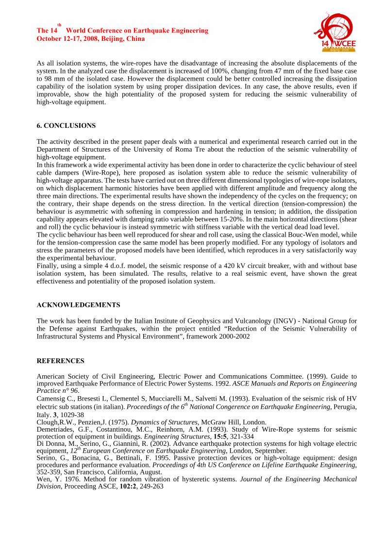
whereas a(t) is the vector whose components are the horizontal and the vertical base ground accelerations. The model has been implemented in Matlab®. In order to verify the effectiveness of the proposed system, two components (N-S and vertical) of the 1980 Irpinia earthquake (Italy), have been used. They have been recorded at Sturno and have a PGA=0.23g and 0.21g respectively. This seismic event is representative of earthquakes with a return period of 500 years for the area in which the substation is placed. The fundamental period of the non-isolated system is 0.61s, and it shifts toward 1.23s for the isolated system; the mode shape changes from a cantilever deformation to a cantilever with a deformable base restrain, which shows a prevalent rotational motion. On the contrary frequency and shape of second mode remain practically unvaried.
0 5 10 15 20 25 30-5
-4
-3
-2
-1
0
1
2
3
4
5x 10
4
Time (sec)
MO
ME
NT
( N
m )
FIXED BASEISOLATED BASE
0 5 10 15 20 25 30-100
-50
0
50
100
Time (sec)
DIS
PLA
CE
ME
NT
(mm
)
FIXED BASEISOLATED BASE
Figure 11 Time-history of the base moment Figure 12 Time-history of the top displacement In Figure 11 and 12 the time-history of base moment and top displacement of the circuit breaker are shown. It is clearly evident a sensible decreasing of the maximum moment, which shift from 49 kNm to 21 kNm, with a reduction of 57%. The effectiveness of the base isolation system is extended along all the time-history, during which the base moment of the isolated case is always lower than the moment of the non-isolated circuit breaker.
The 14th
World Conference on Earthquake Engineering October 12-17, 2008, Beijing, China As all isolation systems, the wire-ropes have the disadvantage of increasing the absolute displacements of the system. In the analyzed case the displacement is increased of 100%, changing from 47 mm of the fixed base case to 98 mm of the isolated case. However the displacement could be better controlled increasing the dissipation capability of the isolation system by using proper dissipation devices. In any case, the above results, even if improvable, show the high potentiality of the proposed system for reducing the seismic vulnerability of high-voltage equipment. 6. CONCLUSIONS The activity described in the present paper deals with a numerical and experimental research carried out in the Department of Structures of the University of Roma Tre about the reduction of the seismic vulnerability of high-voltage equipment. In this framework a wide experimental activity has been done in order to characterize the cyclic behaviour of steel cable dampers (Wire-Rope), here proposed as isolation system able to reduce the seismic vulnerability of high-voltage apparatus. The tests have carried out on three different dimensional typologies of wire-rope isolators, on which displacement harmonic histories have been applied with different amplitude and frequency along the three main directions. The experimental results have shown the independency of the cycles on the frequency; on the contrary, their shape depends on the stress direction. In the vertical direction (tension-compression) the behaviour is asymmetric with softening in compression and hardening in tension; in addition, the dissipation capability appears elevated with damping ratio variable between 15-20%. In the main horizontal directions (shear and roll) the cyclic behaviour is instead symmetric with stiffness variable with the vertical dead load level. The cyclic behaviour has been well reproduced for shear and roll case, using the classical Bouc-Wen model, while for the tension-compression case the same model has been properly modified. For any typology of isolators and stress the parameters of the proposed models have been identified, which reproduces in a very satisfactorily way the experimental behaviour. Finally, using a simple 4 d.o.f. model, the seismic response of a 420 kV circuit breaker, with and without base isolation system, has been simulated. The results, relative to a real seismic event, have shown the great effectiveness and potentiality of the proposed isolation system. ACKNOWLEDGEMENTS The work has been funded by the Italian Institute of Geophysics and Vulcanology (INGV) - National Group for the Defense against Earthquakes, within the project entitled “Reduction of the Seismic Vulnerability of Infrastructural Systems and Physical Environment”, framework 2000-2002 REFERENCES American Society of Civil Engineering, Electric Power and Communications Committee. (1999). Guide to improved Earthquake Performance of Electric Power Systems. 1992. ASCE Manuals and Reports on Engineering Practice n° 96. Camensig C., Bresesti L, Clementel S, Mucciarelli M., Salvetti M. (1993). Evaluation of the seismic risk of HV electric sub stations (in italian). Proceedings of the 6th National Congerence on Earthquake Engineering, Perugia, Italy. 3, 1029-38 Clough,R.W., Penzien,J. (1975). Dynamics of Structures, McGraw Hill, London. Demetriades, G.F., Costantinou, M.C., Reinhorn, A.M. (1993). Study of Wire-Rope systems for seismic protection of equipment in buildings. Engineering Structures, 15:5, 321-334 Di Donna, M., Serino, G., Giannini, R. (2002). Advance earthquake protection systems for high voltage electric equipment, 12th European Conference on Earthquake Engineering, London, September. Serino, G., Bonacina, G., Bettinali, F. 1995. Passive protection devices or high-voltage equipment: design procedures and performance evaluation. Proceedings of 4th US Conference on Lifeline Earthquake Engineering, 352-359, San Francisco, California, August. Wen, Y. 1976. Method for random vibration of hysteretic systems. Journal of the Engineering Mechanical Division, Proceeding ASCE, 102:2, 249-263