Embed Size (px)
Citation preview


This page intentionally left blank
ELECTRICALSAFETY
HANDBOOK
John Cadick, P.E.
Cadick Corporation, Garland, Texas
Mary Capelli-Schellpfeffer, M.D., M.P.A.
CapSchell, Inc., Chicago, Illinois
Dennis K. Neitzel, C.P.E.
AVO Training Institute, Inc., Dallas, Texas
Third Edition
McGRAW-HILL
New York Chicago San Francisco Lisbon London Madrid
Mexico City Milan New Delhi San Juan Seoul
Singapore Sydney Toronto

Copyright © 2006 by The McGraw-Hill Companies, Inc. All rights reserved. Manufactured in theUnited States of America. Except as permitted under the United States Copyright Act of 1976, no partof this publication may be reproduced or distributed in any form or by any means, or stored in a data-base or retrieval system, without the prior written permission of the publisher.
0-07-158912-0
The material in this eBook also appears in the print version of this title: 0-07-145772-0.
All trademarks are trademarks of their respective owners. Rather than put a trademark symbol afterevery occurrence of a trademarked name, we use names in an editorial fashion only, and to the benefit of the trademark owner, with no intention of infringement of the trademark. Where such designations appear in this book, they have been printed with initial caps.
McGraw-Hill eBooks are available at special quantity discounts to use as premiums and sales promotions, or for use in corporate training programs. For more information, please contact GeorgeHoare, Special Sales, at [email protected] or (212) 904-4069.
TERMS OF USE
This is a copyrighted work and The McGraw-Hill Companies, Inc. (“McGraw-Hill”) and its licensorsreserve all rights in and to the work. Use of this work is subject to these terms. Except as permittedunder the Copyright Act of 1976 and the right to store and retrieve one copy of the work, you may notdecompile, disassemble, reverse engineer, reproduce, modify, create derivative works based upon,transmit, distribute, disseminate, sell, publish or sublicense the work or any part of it withoutMcGraw-Hill’s prior consent. You may use the work for your own noncommercial and personal use;any other use of the work is strictly prohibited. Your right to use the work may be terminated if youfail to comply with these terms.
THE WORK IS PROVIDED “AS IS.” McGRAW-HILL AND ITS LICENSORS MAKE NO GUAR-ANTEES OR WARRANTIES AS TO THE ACCURACY, ADEQUACY OR COMPLETENESS OFOR RESULTS TO BE OBTAINED FROM USING THE WORK, INCLUDING ANY INFORMA-TION THAT CAN BE ACCESSED THROUGH THE WORK VIA HYPERLINK OR OTHERWISE, AND EXPRESSLY DISCLAIM ANY WARRANTY, EXPRESS OR IMPLIED,INCLUDING BUT NOT LIMITED TO IMPLIED WARRANTIES OF MERCHANTABILITY ORFITNESS FOR A PARTICULAR PURPOSE. McGraw-Hill and its licensors do not warrant or guarantee that the functions contained in the work will meet your requirements or that its operationwill be uninterrupted or error free. Neither McGraw-Hill nor its licensors shall be liable to you or anyone else for any inaccuracy, error or omission, regardless of cause, in the work or for any damagesresulting therefrom. McGraw-Hill has no responsibility for the content of any information accessedthrough the work. Under no circumstances shall McGraw-Hill and/or its licensors be liable for anyindirect, incidental, special, punitive, consequential or similar damages that result from the use of orinability to use the work, even if any of them has been advised of the possibility of such damages. Thislimitation of liability shall apply to any claim or cause whatsoever whether such claim or cause aris-es in contract, tort or otherwise.
DOI: 10.1036/0071457720

We hope you enjoy thisMcGraw-Hill eBook! If
you’d like more information about this book,its author, or related books and websites,please click here.
Professional
Want to learn more?

To my wife, Sheryl, for her love and support.
John Cadick
To my wife, Brenda Neitzel, who always believed inme and who encouraged me to continue my educationand strive to be the best that I could be; to the U.S.Air Force for giving me my start in an electricalcareer; to all of my employers, who gave mecountless opportunities to learn and progress; andto John Cadick, who believed in me enough to askme to contribute to this book.
Dennis Neitzel
In dedication especially to Michael Allen, the fatherof Sarah, Benjamin, Amelia, and Natalie, with myhope that each will continue to learn the most theycan from books.
Mary Capelli-Schellpfeffer

This page intentionally left blank
vii
CONTENTS
Foreword xvii
Preface xix
Acknowledgments xxi
Chapter 1. Hazards of Electricity 1.1
Introduction / 1.1Glossary / 1.1Hazard Analysis / 1.2Shock / 1.2
Description / 1.2Influencing Factors / 1.3
Arc / 1.7Definition and Description / 1.8Arc Energy Release / 1.9Arc Energy / 1.12Arc Energy Input / 1.12Arcing Voltage / 1.13Arc Surface Area / 1.13Incident Energy / 1.14Arc Burns / 1.16
Blast / 1.16Affected Body Parts / 1.17
General / 1.17Skin / 1.19The Nervous System / 1.20Muscular System / 1.21The Heart / 1.22The Pulmonary System / 1.23
Summary of Causes—Injury and Death / 1.23Shock Effect / 1.23Arc Flash Effect / 1.24Causes of Injury / 1.24Causes of Death / 1.25
Protective Strategies / 1.25References / 1.26
Chapter 2. Electrical Safety Equipment 2.1
Introduction / 2.1Glossary / 2.1General Inspection and Testing Requirements for Electrical
Safety Equipment / 2.2
For more information about this title, click here
Flash and Thermal Protection / 2.2A Note on When to Use Thermal Protective Clothing / 2.2Thermal Performance Evaluation / 2.3Clothing Materials / 2.4Non-Flame-Resistant Materials / 2.5Flame-Resistant Materials / 2.6Work Clothing / 2.9Flash Suits / 2.11Head, Eye, and Hand Protection / 2.13
Head and Eye Protection / 2.14Hard Hats / 2.14Safety Glasses, Goggles, and Face Shields / 2.15
Rubber-Insulating Equipment / 2.15Rubber Gloves / 2.16Rubber Mats / 2.20Rubber Blankets / 2.21Rubber Covers / 2.22Line Hose / 2.25Rubber Sleeves / 2.26In-Service Inspection and Periodic Testing of Rubber Goods / 2.29
Hot Sticks / 2.44Description and Application / 2.44When to Use / 2.47How to Use / 2.47Testing Requirements / 2.47
Insulated Tools / 2.48Description and Application / 2.48When to Use / 2.49How to Use / 2.49
Barriers and Signs / 2.49Barrier Tape / 2.49Signs / 2.49When and How to Use / 2.50
Safety Tags, Locks, and Locking Devices / 2.51Safety Tags / 2.51Locks and Multiple-Lock Devices / 2.52Locking Devices / 2.53When/Where to Use Lockout Tagout / 2.53
Voltage-Measuring Instruments / 2.54Safety Voltage Measurement / 2.54Proximity Testers / 2.55Contact Testers / 2.56Selecting Voltage-Measuring Instruments / 2.57Instrument Condition / 2.59Low Voltage Voltmeter Safety Standards / 2.60Three-Step Voltage Measurement Process / 2.60General Considerations for Low-Voltage Measuring Instruments / 2.62
Safety Grounding Equipment / 2.63The Need for Safety Grounding / 2.63Safety Grounding Switches / 2.64Safety Grounding Jumpers / 2.65Selecting Safety Grounding Jumpers / 2.70Installation and Location / 2.74
Ground Fault Circuit Interrupters / 2.74Operating Principles / 2.74Applications / 2.75
Safety Electrical One-Line Diagram / 2.78The Electrician’s Safety Kit / 2.78References / 2.79
viii CONTENTS
CONTENTS ix
Chapter 3. Safety Procedures and Methods 3.1
Introduction / 3.1The Six-Step Safety Method / 3.1
Think—Be Aware / 3.2Understand Your Procedures / 3.2Follow Your Procedures / 3.2Use Appropriate Safety Equipment / 3.2Ask If You Are Unsure, and Do Not Assume / 3.2Do Not Answer If You Do Not Know / 3.3
Pre-Job Briefings / 3.3Definition / 3.3What Should Be Included? / 3.3When Should Pre-Job Briefings Be Held? / 3.3
Energized or De-Energized? / 3.3The Fundamental Rules / 3.3A Hot-Work Decision Tree / 3.5After the Decision Is Made / 3.6
Safe Switching of Power Systems / 3.6Introduction / 3.6Remote Operation / 3.7Operating Medium-Voltage Switchgear / 3.7Operating Low-Voltage Switchgear / 3.11Operating Molded-Case Breakers and Panelboards / 3.15Operating Enclosed Switches and Disconnects / 3.17Operating Open-Air Disconnects / 3.18Operating Motor Starters / 3.20
Energy Control Programs / 3.23General Energy Control Programs / 3.23Specific Energy Control Programs / 3.24Basic Energy Control Rules / 3.24
Lockout-Tagout / 3.26Definition and Description / 3.26When to Use Locks and Tags / 3.26Locks without Tags or Tags without Locks / 3.26Rules for Using Locks and Tags / 3.27Responsibilities of Employees / 3.27Sequence / 3.28Lock and Tag Application / 3.28Isolation Verification / 3.28Removal of Locks and Tags / 3.28Safety Ground Application / 3.29Control Transfer / 3.31Nonemployees and Contractors / 3.31Lockout-Tagout Training / 3.31Procedural Reviews / 3.32
Voltage-Measurement Techniques / 3.32Purpose / 3.32Instrument Selection / 3.32Instrument Condition / 3.33Three-Step Measurement Process / 3.34What to Measure / 3.34How to Measure / 3.36
Placement of Safety Grounds / 3.37Safety Grounding Principles / 3.37Safety Grounding Location / 3.38Application of Safety Grounds / 3.38The Equipotential Zone / 3.43
Removal of Safety Grounds / 3.44Control of Safety Grounds / 3.44
Flash Hazard Calculations and Approach Distances / 3.46Introduction / 3.46Approach Distance Definitions / 3.46Determining Shock Hazard Approach Distances / 3.46Calculating the Flash Hazard Minimum Approach Distance (Flash Protection Boundary) / 3.49
Calculating the Required Level of Arc Protection (Flash Hazard Calculations) / 3.51Introduction / 3.51The Lee Method / 3.52Methods Outlined in NFPA 70E / 3.52IEEE Standard Std 1584-2002 / 3.53Software Solutions / 3.55Required PPE for Crossing the Flash Hazard Boundary / 3.55A Simplified Approach to the Selection of Protective Clothing / 3.56
Barriers and Warning Signs / 3.56Illumination / 3.61Conductive Clothing and Materials / 3.61Confined Work Spaces / 3.62
Tools and Test Equipment / 3.62General / 3.62Authorized Users / 3.62Visual Inspections / 3.63Electrical Tests / 3.63Wet and Hazardous Environments / 3.63
Field Marking of Potential Hazards / 3.65The One-Minute Safety Audit / 3.65References / 3.66
Chapter 4. Grounding of Electrical Systems and Equipment 4.1
Introduction / 4.1Electric Shock Hazard / 4.1General Requirements for Grounding and Bonding / 4.2
Definitions / 4.2Grounding of Electrical Systems / 4.3Grounding of Electrical Equipment / 4.6Bonding of Electrically Conductive Materials and Other Equipment / 4.6Performance of Fault Path / 4.8Arrangement to Prevent Objectionable Current / 4.8Alterations to Stop Objectionable Current / 4.8Temporary Currents Not Classified as Objectionable Current / 4.8Connection of Grounding and Bonding Equipment / 4.8Protection of Ground Clamps and Fittings / 4.9Clean Surfaces / 4.9
System Grounding / 4.9Purposes of System Grounding / 4.9Grounding Service-Supplied Alternating-Current Systems / 4.9Conductors to Be Grounded—Alternating-Current Systems / 4.11Main Bonding Jumper / 4.11Grounding Electrode System / 4.12Grounding Electrode System Resistance / 4.14Grounding Electrode Conductor / 4.14Grounding Conductor Connection to Electrodes / 4.16Bonding / 4.18
x CONTENTS
Equipment Grounding / 4.19Equipment to Be Grounded / 4.19Grounding Cord- and Plug-Connected Equipment / 4.19Equipment Grounding Conductors / 4.21Sizing Equipment Grounding Conductors / 4.22Use of Grounded Circuit Conductor for Grounding Equipment / 4.22Ferroresonance / 4.25
Summary / 4.27
Chapter 5. Electrical Maintenance and Its Relationship to Safety 5.1
Introduction / 5.1The Safety-Related Case for Electrical Maintenance / 5.1
Overview / 5.1Regulatory / 5.2Relationship of Improperly Maintained Electrical Equipment to the Hazards of Electricity / 5.2
Hazards Associated with Electrical Maintenance / 5.3The Economic Case for Electrical Maintenance / 5.3Reliability Centered Maintenance (RCM) / 5.4
What is Reliability Centered Maintenance? / 5.5A Brief History of RCM / 5.5RCM in the Industrial and Utility Arena / 5.5The Primary RCM Principles / 5.6Failure / 5.8Maintenance Actions in an RCM Program / 5.8Impact of RCM on a Facilities Life Cycle / 5.9Conclusion / 5.10
The Eight Step Maintenance Program / 5.10Introduction / 5.11Step 1—Plan / 5.11Step 2—Inspect / 5.11Step 3—Clean / 5.12Step 4—Tighten / 5.12Step 5—Lubricate / 5.12Step 6—Test / 5.13Step 7—Record / 5.13Step 8—Evaluate / 5.13
Frequency of Maintenance / 5.14Determining Testing Intervals / 5.14Summary / 5.14
Maintenance Requirements for Specific Equipment and Locations / 5.14General Maintenance Requirements / 5.14Substations, Switchgear, Panel Boards, Motor Control Centers, and Disconnect Switches / 5.15
Fuse Maintenance Requirements / 5.16Molded-Case Circuit Breakers / 5.16Low-Voltage Power Circuit Breakers / 5.18Medium Voltage Circuit Breakers / 5.20Protective Relays / 5.21Rotating Equipment / 5.23Portable Electric Tools and Equipment / 5.23Personal Safety and Protective Equipment / 5.24
Conclusion / 5.24References / 5.24
CONTENTS xi
Chapter 6. Regulatory and Legal Safety Requirements and Standards 6.1
Introduction / 6.1The Regulatory Bodies / 6.1
The American National Standards Institute (ANSI) / 6.1The Institute of Electrical and Electronic Engineers (IEEE) / 6.3National Fire Protection Association (NFPA) / 6.3American Society for Testing and Materials (ASTM) / 6.4American Society of Safety Engineers (ASSE) / 6.5The Occupational Safety and Health Administration (OSHA) / 6.6Other Electrical Safety Organizations / 6.12
The National Electrical Safety Code (NESC)—ANSI C-2 / 6.12General Description / 6.12Industries and Facilities Covered / 6.13Technical/Safety Items Covered / 6.13
The National Electrical Code (NEC)—ANSI/NFPA 70 / 6.14General Description / 6.14Industries and Facilities Covered / 6.15Technical and Safety Items Included / 6.15
Electrical Equipment Maintenance—ANSI/NFPA 70B / 6.15General Description / 6.15Industries and Facilities Covered / 6.16Technical and Safety Items Covered / 6.16
Standard for Electrical Safety in the Workplace—ANSI/NFPA 70E / 6.16General Description / 6.16Industries and Facilities Covered / 6.17Technical Safety Items Covered / 6.18
The American Society for Testing and Materials (ASTM) Standards / 6.19Occupational Safety and Health Administration (OSHA) Standards / 6.19
Overview / 6.19General Industry / 6.19Construction Industry / 6.22
Chapter 7. Accident Prevention, Accident Investigation,Rescue, and First Aid 7.1
Accident Prevention / 7.1Individual Responsibility / 7.1Installation Safety / 7.1Power System Studies / 7.3
First Aid / 7.7General First Aid / 7.8Resuscitation (Artificial Respiration) / 7.12Heart-Lung Resuscitation / 7.12
Rescue Techniques / 7.14General Rescue Procedures / 7.14Elevated Rescue / 7.18Confined-Space Rescue / 7.30Ground-Level Rescue / 7.31
Accident Investigation / 7.37Purpose / 7.37General Rules / 7.38Data Gathering / 7.38Accident Analysis / 7.40
xii CONTENTS
Chapter 8. Medical Aspects of Electrical Trauma 8.1
Introduction / 8.1Statistical Survey / 8.1
Non-Occupational Electrical Trauma / 8.4Fatality and Injury Related Costs / 8.4
Electrical Events / 8.6Electrocution and Electrical Fatalities / 8.7
Medical Aspects / 8.8Non-Electrical Effects in Electrical Events / 8.10Stabilization and Initial Evaluation / 8.13Medical and Surgical Intervention / 8.14
Rehabilitation Focus and Return to Work Planning / 8.16Reentry to Employment Settings / 8.16Plateau in Recovery / 8.16
References / 8.18
Chapter 9. Low-Voltage Safety Synopsis 9.1
Introduction / 9.1Low-Voltage Equipment / 9.1
Extension Cords / 9.2Plug- and Cord-Connected Equipment / 9.3Current Transformers / 9.5
Grounding Low-Voltage Systems / 9.5What Is a Ground? / 9.5Bonding Versus Grounding / 9.6Voltage Hazards / 9.6System Grounds / 9.8Equipment Grounds / 9.11Ground Fault Circuit Interrupters / 9.14
Safety Equipment / 9.14Overview / 9.14Hard Hats / 9.14Eye Protection / 9.15Arc Protection / 9.18Rubber Insulating Equipment / 9.18Voltage-Testing Devices / 9.18
Safety Procedures / 9.20General / 9.20Approach Distances / 9.20Voltage Measurement / 9.20Locking and Tagging / 9.21Closing Protective Devices After Operation / 9.21
Electrical Safety Around Electronic Circuits / 9.21The Nature of the Hazard / 9.21Special Safety Precautions / 9.22
Stationary Battery Safety / 9.23Introduction / 9.23Basic Battery Construction / 9.24Safety Hazards of Stationary Batteries / 9.25Battery Safety Procedures / 9.25
Chapter 10. Medium- and High-Voltage Safety Synopsis 10.1
Introduction / 10.1High-Voltage Equipment / 10.1
Current Transformers / 10.1
CONTENTS xiii
Grounding Systems of Over 1000 V / 10.3What Is a Ground? / 10.3Bonding Versus Grounding / 10.4Voltage Hazards / 10.5System Grounds / 10.5Equipment Grounds / 10.7
Safety Equipment / 10.7Overview / 10.7Hard Hats / 10.8Eye Protection / 10.8Arc Protection / 10.9Rubber Insulating Equipment / 10.9Voltage-Testing Devices / 10.9
Safety Procedures / 10.12General / 10.12Approach Distances / 10.12Voltage Measurement / 10.13Locking and Tagging / 10.13Closing Protective Devices After Operation / 10.13
Chapter 11. Human Factors in Electrical Safety 11.1
Introduction / 11.1Background / 11.1
Power Systems and Human Factors / 11.3Visualization / 11.4Cognitive Ergonomics / 11.4
Summary / 11.8References / 11.8
Chapter 12. Safety Management and Organizational Structure 12.1
Introduction / 12.1Electrical Safety Program Structure / 12.1Electrical Safety Program Development / 12.2
The Company Electrical Safety Team / 12.2Company Safety Policy / 12.4Assessing the Need / 12.4Problems and Solutions / 12.4Program Implementation / 12.5Examples / 12.5Company Safety Procedures / 12.7Results Assessment / 12.7
Employee Electrical Safety Teams / 12.8Reason / 12.8Method / 12.8
Safety Meetings / 12.9Who Attends / 12.9What Material Should Be Covered / 12.9When Meetings Should Be Held / 12.10Where Meetings Should Be Held / 12.10How Long Meetings Should Be / 12.10Evaluation of Safety Meetings / 12.10
Outage Reports / 12.11Safety Audits / 12.11
xiv CONTENTS
Description / 12.11Purposes / 12.12Procedure / 12.12The Audit Team / 12.14Audit Tools / 12.14Follow-Up / 12.14Internal versus External Audits / 12.14
Chapter 13. Safety Training Methods and Systems 13.1
Introduction / 13.1Safety Training Definitions / 13.1Training Myths / 13.2Conclusion / 13.3
Elements of a Good Training Program / 13.3Classroom Training / 13.3On-the-Job Training (OJT) / 13.5Self-training / 13.6Conclusion / 13.6
On-the-Job Training / 13.6Setup / 13.6Implementation / 13.8Evaluation / 13.8Conclusion / 13.9
Training Consultants and Vendors / 13.9Canned Programs and Materials / 13.9Tailored Programs / 13.10Training Analysis / 13.10Evaluating Training Vendors and Consultants / 13.11Conclusion / 13.11
Training Program Setup—A Step-By-Step Method / 13.12Introduction / 13.12Background / 13.12A Plan / 13.14Analyze / 13.14Design / 13.16Develop / 13.17Implementation / 13.18Evaluation / 13.18Modification / 13.19
Index I.1
CONTENTS xv

This page intentionally left blank
FOREWORD
Electricity has been recognized as dangerous since it began to be used for street lighting inlarge cities in the northeastern United States in the late 1800s. People received severe shocksand were frequently electrocuted as they made contact with energized electrical equipment.Inadequate electrical installation often resulted in fires, and standard installation methods didnot exist.
At that time, even though fires and electrocutions were occurring, the use of electricityquickly expanded to other parts of the United States. Electrical designs and installationsvaried widely from one facility to another. Injury data and economic losses illustrated thatboth fire and electrocution were hazards, and insurance companies recognized the impor-tance of standardization. If an installation standard could be developed, both electrocutionand fire could be reduced.
The system of voluntary electrical standards that currently exists was developed after fire,and electrocution became recognized electrical hazards. The system of codes and standardsthat guides installations consists of documents generated by standards-developing organizations,third-party inspection of electrical equipment, and enforcement by inspecting organizations.The system does a good job of keeping the public safe from both electrocution and fires, pro-vided the electrical equipment doors are latched, adequately maintained, and the equipmentis operating normally.
In recent years, the community has begun to recognize that in addition to fire and electro-cution, arc-flash and arc-blast hazards also result in injury. The knowledge base about thesehazards is expanding but is not yet complete. The community knows that as the distancebetween a worker and an electrical hazard decreases, the degree of exposure increases.Workers must understand that they are exposed to these hazards until an electrically safework condition has been established, as explained in this handbook.
Before an electrically safe work condition exists, workers are exposed to all hazards asso-ciated with electrical energy, in many different ways:
Electrical equipment, devices, and components have a life expectancy, and control devicessometimes malfunction. When a failure occurs, a worker is expected to identify the problem,repair the problem, and restore the equipment to normal service.
To extend the life of electrical equipment, the equipment must be maintained. Although theelectrical energy sometimes is removed before a worker begins a maintenance task, thosetasks often are executed while the source of electricity is energized.
Equipment and circuits sometimes are modified to add new devices or circuits. Short-termemployees may be expected to work in an environment that includes exposure to energizedelectrical circuits and components. Consultant and service employees are frequentlyexposed to energized electrical equipment and circuits.
When a problem exists that causes equipment to operate other than normally, a workermight open a door or remove a cover and expose an energized electrical conductor orcomponent. In many cases, the worker might troubleshoot while the circuit is energized.Components and conductors might be added within a piece of equipment while the equip-ment or parts of the equipment remain energized.
xvii
Copyright © 2006 by The McGraw-Hill Companies, Inc. Click here for terms of use.
xviii FOREWORD
After correcting a problem, workers sometimes create further hazardous conditions: leave anequipment door ajar, with latches open; replace covers with a minimum number of screws;and remove devices, leaving penetrations through a door.
In recent years, the electrical community has begun to understand that workers areexposed to many different electrical hazards. Workers certainly should not be unnecessarilyexposed to hazards. Workers should understand how and when they could be exposed to ahazard and how to assess the hazard and risk of injury. They must also understand how toselect and use work practices that minimize or eliminate risk of injury and how to select andwear protective equipment that will minimize or eliminate that risk.
Employees must be trained to understand the concepts discussed in each chapter. Theauthors of this handbook are warriors in the fight for electrical safe workplaces. This newedition provides critical, up-to-date information for employers about how to avoid injury. Allof the information is here in the handbook, and work practices, procedures, and the overallelectrical safety program should embody the ideas discussed herein. I highly recommend thisvaluable resource to employers as they join the growing effort to ensure that their workersremain safe. Providing a safe work place is not only an economical asset, it is the right thingto do.
Ray A. Jones, P.E.NFPA 70E Technical Committee Chair
PREFACE
It seems like only a few days since the second edition of this handbook was completed;however, in the five years that have passed, amazing things have happened in the world ofsafety. First, the 2000 edition of NFPA 70E has become the 2004 edition with a multitudeof changes. Second, the electrical world seems to have become much more aware of thehazards of electricity and has started to embrace many, if not all, of the more modernsafety requirements, such as flash-hazard evaluations. Finally, companies throughout theworld are starting to gear up to provide enhanced safety programs for their personnel andwork in teams to achieve that goal.
The Electrical Safety Handbook has continued to receive remarkably broad accep-tance in the electrical safety world, perhaps because it is the only independent refer-ence source for all of the various aspects of electrical safety. With this in mind, wehave expanded virtually all of the previous chapters in this edition as well as added abrand new chapter covering the safety aspects of electrical maintenance. We trulyhope that the increased detail in the old chapters and the addition of the new chapterwill be met with the same enthusiasm as the previous edition.
Chapters 1, 2, and 3 continue to serve as the central core of the book, by presentingthe case for electrical safety (Chapter 1), a broad coverage of electrical safety equip-ment (Chapter 2), and a detailed coverage of electrical safety procedures (Chapter 3).The changes in Chapter 3 should be of special interest to the reader since we haveupdated the arc energy calculations to be consistent with new industry innovations asintroduced in IEEE Standard Std 1584 and NFPA 70E.
Chapter 4 has been revised to include references to the 2005 edition of the NationalElectrical Code (NEC). Additional information has also been added that includes fer-roresonance. Chapter 4 continues to provide a detailed overview of the general require-ments for grounding and bonding electrical systems and equipment. This chapter alsoprovides some needed explanations, illustrations, and calculations necessary for applyingthe requirements of NEC Article 250 as well as OSHA 29 CFR 1910.304(f). It should beemphasized, however that this chapter is not intended to replace or be a substitute for therequirements of the current NEC or OSHA regulations. Always utilize the most currentstandards and regulations when designing, installing, and maintaining the grounding sys-tems within a facility.
Chapter 5, new to this edition, introduces a broad coverage of safety-related mainte-nance concepts. The chapter is not intended to be a maintenance reference, rather it intro-duces the economic and safety-related reasons for performing maintenance on an electri-cal power system. We also introduce the current philosophies on good maintenanceincluding discussions of topics such as reliability-centered, predictive, preventive, andcondition-based maintenance. Finally, the chapter covers the eight broad steps of a goodmaintenance program and introduces a cross section of maintenance and testing proce-dures for a variety of electrical equipment.
Chapter 6 (Chapter 5 in the second edition), updates the previous coverage on theconsensus and mandatory standards and regulations in the workplace. Also included areexplanations of several of the general industry OSHA regulations, which are quoted
xix
Copyright © 2006 by The McGraw-Hill Companies, Inc. Click here for terms of use.
directly from the Federal Registers preamble as well as the Directorate of Compliancedocuments.
The specific information reprinted from OSHA has been updated to the most recentversions as of the date of this publication. As before, the reader should always refer tothe OSHA publications (available at www.osha.gov) for the most recent information.
Chapter 7 (Chapter 6 in the second edition) has been expanded and rewritten in severalkey ways. New information, addressing the relationship of proper engineering and safety,has been added showing the reader how they can engineer safety hazards out of existence.Also, the section on first aid and CPR has been brought more up-to-date.
In Chapter 8, a statistical survey of electrical injuries and fatalities is added.Details about the possible medical scenarios following exposure to electrical hazardsare included to assist the reader in appreciating how survivors of a multivictim electri-cal incident may share an event, but not necessarily the same effects to their bodies.Graphs and tables, new to the handbook’s third edition, give quick summaries of enhancedinformation. Figures are presented to explain the basic principle that injury results with thetransformation and transfer of energy.
Chapters 9 and 10 (Chapters 8 and 9 in the second edition) have been updated withnew information taken from Chapters 2 and 3. As before, these two chapters serve as aquick reference to the reader for low-, medium-, and high-voltage safety.
Added to the topic of human factors now found in Chapter 11 is a historical per-spective. Insights regarding human factors engineering developed within the civiliannuclear power industry are also included.
Chapter 12 (Chapter 11 in the second edition) has been updated to include informa-tion garnered from the collective experience of the authors since the second editionwas published. Of special importance is the material covering the interrelationshipsamong management, labor, and legal counsel.
Chapter 13 (Chapter 12 in the second edition) has a significant new section covering amethod to develop a training that will provide a more consistent and compliant safety pro-gram. By using tried and tested educational methods, the new sections show the reader in astep-by-step manner how to create their training program.
John Cadick, P.E.
Mary Capelli-Schellpfeffer, M.D., M.P.A.
Dennis K. Neitzel, C.P.E.
xx PREFACE
ACKNOWLEDGMENTS
The authors gratefully acknowledge contributions, permissions, and assistance from thefollowing individuals and organizations:
Kathy Hooper, ASTM; Robert L. Meltzer, ASTM; Laura Hannan, TEGAM Incorporated;Raymond L. Erickson, Eaton Corporation, Cutler-Hammer Products; H.G. Brosz, Brosz andAssociates Archives; P. Eng, Brosz and Associates Archives; Ellis Lyons, W.H. Salisburyand Company; Tom Gerard, TIF Instruments, Inc., Miami, Florida; LaNelle Morris,Direct Safety Company, Phoenix, Arizona; Tony Quick, Santronics Inc.; Ed DaCruz,Siebe North, Inc.; Benjamin L. Bird, CIP Insulated Products; E.T. Thonson, AVO BiddleInstruments, Blue Bell, Pennsylvania; Terry Duchaine, Ideal Industries, Inc., Sycamore,Illinois; Mary Kay S. Kopf, DuPont Fibers; Stephen Gillette, Electrical ApparatusDivision of Siemens Energy and Automation, Inc.; Mary Beth Stahl, Mine SafetyAppliances Company; Debbie Prikryl, Encon Safety Products; Craig H. Seligman,NOMEX® III Work Clothing, Workrite Uniform Company, Oxnard, California; KareemM. Irfan, Square D Company, A.B. Chance Co., AVO Multi-Amp Institute; Dr. BrianStevens, Ph.D., Phelps Dodge Mining Company; Jason Saunders, Millennium InorganicChemicals; Cindy Chatman, Bulwark; Alan Mark Franks; Sandy Young; Bruce McClung;Dr. Raphael C. Lee, M.D., Sc.D., and Zoe G. Foundotos.
John Cadick
AVO Training Institute, Inc. (a Subsidiary of Megger); Erico, Inc. (Cadweld); Ronald P.O’Riley, Electrical Grounding (Delmar Publishers); National Fire Protection Association,2005 National Electrical Code Handbook (NFPA).
Dennis Neitzel
Dr. Capelli-Schellpfeffer’s research was supported in part by grant R01 OH04136-02from the U.S. Center for Disease Control and Prevention (CDC) and the NationalInstitute of Occupational Safety and Health (NIOSH). Her comments do not representofficial agency views.
Mary Capelli-Schellpfeffer
xxi
Copyright © 2006 by The McGraw-Hill Companies, Inc. Click here for terms of use.

This page intentionally left blank

ELECTRICALSAFETY
HANDBOOK

This page intentionally left blank
1.1
CHAPTER 1HAZARDS OF ELECTRICITY
INTRODUCTION
Modern society has produced several generations who have grown accustomed to electric-ity. This acclimatization has been made easier by the fact that electricity is silent, invisible,odorless, and has an “automatic” aspect to it. In the late 1800s, hotels had to place signsassuring their guests that electricity is harmless. By the late 1900s, signs had to be hung toremind us that electricity is a hazard. In fact, the transition of electricity from a silentcoworker to a deadly hazard is a change that many cannot understand until it happens tothem. Because of these facts, the total acceptance of an electrical safety procedure is arequirement for the health and welfare of workers.
Understanding the steps and procedures employed in a good electrical safety programrequires an understanding of the nature of electrical hazards. Although they may have trou-ble writing a concise definition, most people are familiar with electric shock. This oftenpainful experience leaves its memory indelibly etched on the human mind. However, shockis only one of the electrical hazards. There are two others—arc and blast. This chapterdescribes each of the three hazards and explains how each affects the human body.
Understanding the nature of the hazards is useless unless protective strategies are devel-oped to protect the worker. This chapter also includes a synopsis of the types of protectivestrategies that should be used to protect the worker.
GLOSSARY
Arc (electric) The heat and light energy release that is caused by the electrical breakdown of and subsequent electrical discharge through anelectrical insulator, such as air.
Arc energy input The total amount of energy delivered by the power system to the arc. This energy will be manifested in many forms includinglight, heat, and mechanical (pressure) energy.
Arc incident energy The amount of energy delivered by an electric arc to the clothing or body of a worker. This amount of energy will be somewhatless than the arc energy based on factors in the workplace.
Arc-flash See Arc
Arc-resistant Metal-clad switchgear which features strengthened mechanicalswitchgear construction as well as pressure relief systems. Arc-resistant
switchgear is designed to minimize the probability of an
Copyright © 2006 by The McGraw-Hill Companies, Inc. Click here for terms of use.
1.2 CHAPTER ONE
arc-flash as well as contain the energy in the event that oneoccurs.
Blast (electric) The explosive effect caused by the rapid expansion of air and other vaporized materials that are a superheated by the suddenpresence of an electric arc.
Contractor muscle A muscle whose contraction bends or closes a joint. The bicep is aflexor muscle.
Electrocution Death caused by the passage of electricity through the body. Death caused by electric shock.
Extensor muscle A muscle whose contraction extends or stretches a body part. The tricep is an extensor muscle.
Fibrillation Rapid and inefficient contraction of muscle fibers of the heart caused by disruption of nerve impulses.
Flash See Arc
Horny layer The commonly applied name for the stratum corneum layer of the epidermis. The stratum corneum is called the horny layerbecause its cells are toughened like an animal’s horn.
Plasma A high-temperature, electrically ionized gas. Because of the high temperatures and electrical characteristics of a plasma, it isusually identified as a fourth state of matter. The othersincluding solid, liquid, and gas.
Shock circuit The path that electric current takes through the body. If the shock circuit includes critical organs, severe trauma is more likelythan if it does not.
Shock (electric) The physical stimulation or trauma that occurs as a result of electric current passing through the body.
HAZARD ANALYSIS
The division of the electrical power hazard into three components is a classic approach usedto simplify the selection of protective strategies. The worker should always be aware thatelectricity is the single root cause of all of the injuries described in this and subsequentchapters. That is, the worker should treat electricity as the hazard and select protectionaccordingly.
SHOCK
Description
Electric shock is the physical stimulation that occurs when electric current flows throughthe human body. The distribution of current flow through the body is a function of the resis-tance of the various paths through which the current flows. The final trauma associated withthe electric shock is usually determined by the most critical path called the shock circuit.The symptoms may include a mild tingling sensation, violent muscle contractions, heartarrhythmia, or tissue damage. Detailed descriptions of electric current trauma are includedin Chap. 8. For the purposes of this chapter, tissue damage may be attributed to at least twomajor causes.
HAZARDS OF ELECTRICITY 1.3
Burning. Burns caused by electric current are almost always third-degree because theburning occurs from the inside of the body. This means that the growth centers aredestroyed. Electric-current burns can be especially severe when they involve vital internalorgans.
Cell Wall Damage. Research funded by the Electric Power Research Institute (EPRI) hasshown that cell death can result from the enlargement of cellular pores due to high-intensityelectric fields.1 This research has been performed primarily by Dr. Raphael C. Lee and hiscolleagues at the University of Chicago. This trauma called electroporation allows ions toflow freely through the cell membranes, causing cell death.
Influencing Factors
Several factors influence the severity of electrical shock. These factors include the physicalcondition and responses of the victim, the path of the current flow, the duration of the cur-rent flow, the magnitude of the current, the frequency of the current, and the voltage mag-nitude causing the shock.
Physical Condition and Physical Response. The physical condition of the individualgreatly influences the effects of current flow. A given amount of current flow will usuallycause less trauma to a person in good physical condition. Moreover, if the victim of theshock has any specific medical problems such as heart or lung ailments, these parts of thebody will be severely affected by relatively low currents. A diseased heart, for example, ismore likely to suffer ventricular fibrillation than a healthy heart.
Current Duration. The amount of energy delivered to the body is directly proportional tothe length of time that the current flows; consequently, the degree of trauma is also directlyproportional to the duration of the current. Three examples illustrate this concept:
1. Current flow through body tissues delivers energy in the form of heat. The magnitudeof energy may be approximated by
J = I 2Rt (1.1)
where J = energy, joulesI = current, amperes
R = resistance of the current path through the body, ohmst = time of current flow, seconds
If sufficient heat is delivered, tissue burning and/or organ shutdown can occur. Note that theamount of heat that is delivered is directly proportional to the duration of the current (t).
2. Some portion of the externally caused current flow will tend to follow the current pathsused by the body’s central nervous system. Since the external current is much larger thanthe normal current flow, damage can occur to the nervous system. Note that nervous sys-tem damage can be fatal even with relatively short durations of current; however,increased duration heightens the chance that damage will occur.
3. Generally, a longer duration of current through the heart is more likely to cause ven-tricular fibrillation. Fibrillation seems to occur when the externally applied electric fieldoverlaps with the body’s cardiac cycle. The likelihood of this event increases with time.
Frequency. Table 1.1 lists the broad relationships between frequency and the harmfuleffects of current flow through the body. Note that at higher frequencies, the effects of
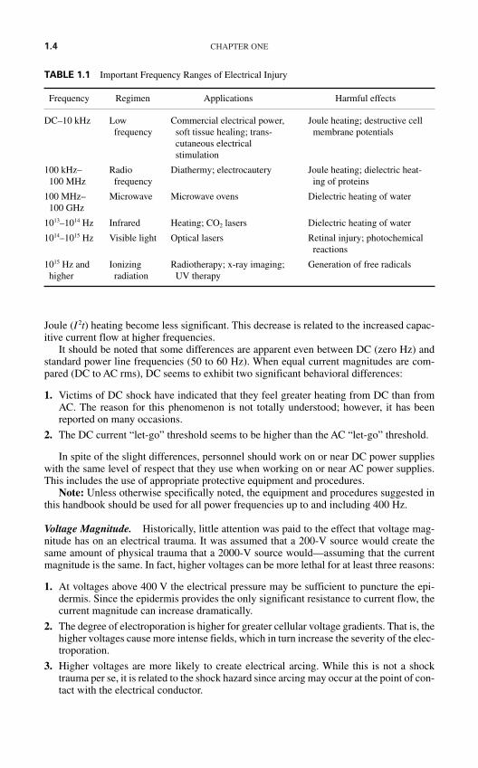
1.4 CHAPTER ONE
Joule (I 2t) heating become less significant. This decrease is related to the increased capac-itive current flow at higher frequencies.
It should be noted that some differences are apparent even between DC (zero Hz) andstandard power line frequencies (50 to 60 Hz). When equal current magnitudes are com-pared (DC to AC rms), DC seems to exhibit two significant behavioral differences:
1. Victims of DC shock have indicated that they feel greater heating from DC than fromAC. The reason for this phenomenon is not totally understood; however, it has beenreported on many occasions.
2. The DC current “let-go” threshold seems to be higher than the AC “let-go” threshold.
In spite of the slight differences, personnel should work on or near DC power supplieswith the same level of respect that they use when working on or near AC power supplies.This includes the use of appropriate protective equipment and procedures.
Note: Unless otherwise specifically noted, the equipment and procedures suggested inthis handbook should be used for all power frequencies up to and including 400 Hz.
Voltage Magnitude. Historically, little attention was paid to the effect that voltage mag-nitude has on an electrical trauma. It was assumed that a 200-V source would create thesame amount of physical trauma that a 2000-V source would—assuming that the currentmagnitude is the same. In fact, higher voltages can be more lethal for at least three reasons:
1. At voltages above 400 V the electrical pressure may be sufficient to puncture the epi-dermis. Since the epidermis provides the only significant resistance to current flow, thecurrent magnitude can increase dramatically.
2. The degree of electroporation is higher for greater cellular voltage gradients. That is, thehigher voltages cause more intense fields, which in turn increase the severity of the elec-troporation.
3. Higher voltages are more likely to create electrical arcing. While this is not a shocktrauma per se, it is related to the shock hazard since arcing may occur at the point of con-tact with the electrical conductor.
TABLE 1.1 Important Frequency Ranges of Electrical Injury
Frequency Regimen Applications Harmful effects
DC–10 kHz Low Commercial electrical power, Joule heating; destructive cell frequency soft tissue healing; trans- membrane potentials
cutaneous electrical stimulation
100 kHz– Radio Diathermy; electrocautery Joule heating; dielectric heat-100 MHz frequency ing of proteins
100 MHz– Microwave Microwave ovens Dielectric heating of water100 GHz
1013–1014 Hz Infrared Heating; CO2 lasers Dielectric heating of water
1014–1015 Hz Visible light Optical lasers Retinal injury; photochemical reactions
1015 Hz and Ionizing Radiotherapy; x-ray imaging; Generation of free radicalshigher radiation UV therapy
HAZARDS OF ELECTRICITY 1.5
Current Magnitude. The magnitude of the current that flows through the body obeysOhm’s law, that is,
(1.2)
where I = current magnitude, amperes (A)E = applied voltage, volts (V)R = resistance of path through which current flows, ohms (Ω)
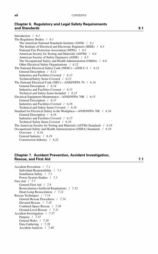
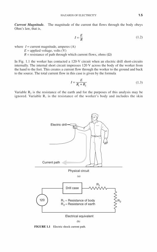
In Fig. 1.1 the worker has contacted a 120-V circuit when an electric drill short-circuitsinternally. The internal short circuit impresses 120 V across the body of the worker fromthe hand to the feet. This creates a current flow through the worker to the ground and backto the source. The total current flow in this case is given by the formula
(1.3)
Variable R2 is the resistance of the earth and for the purposes of this analysis may beignored. Variable R1 is the resistance of the worker’s body and includes the skin
IE
R R= +1 2
IER
=
120
Drill caseR1
R2R1 = Resistance of bodyR2 = Resistance of earth
Electrical equivalent
(b)
FIGURE 1.1 Electric shock current path.
Electric drill
Current path
Physical circuit
(a)
1.6 CHAPTER ONE
resistance, the internal body resistance, and the resistance of the shoes where they con-tact the earth.
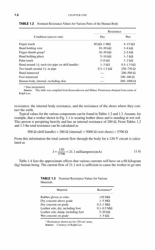
Typical values for the various components can be found in Tables 1.2 and 1.3. Assume, forexample, that a worker shown in Fig. 1.1 is wearing leather shoes and is standing in wet soil.This person is perspiring heavily and has an internal resistance of 200 Ω. From Tables 1.2and 1.3 the total resistance can be calculated as
500 Ω (drill handle) + 200 Ω (internal) + 5000 Ω (wet shoes) = 5700 Ω
From this information the total current flow through the body for a 120-V circuit is calcu-lated as
(1.4)
Table 1.4 lists the approximate effects that various currents will have on a 68-kilogram(kg) human being. The current flow of 21.1 mA is sufficient to cause the worker to go into
I = =1205700
21 1. milliamperes(mA)
TABLE 1.3 Nominal Resistance Values for VariousMaterials
Material Resistance*
Rubber gloves or soles >20 MΩDry concrete above grade 1–5 MΩDry concrete on grade 0.2–1 MΩLeather sole, dry, including foot 0.1–0.5 MΩLeather sole, damp, including foot 5–20 kΩWet concrete on grade 1–5 kΩ
* Resistances shown are for 130-cm2 areas.Source: Courtesy of Ralph Lee.
TABLE 1.2 Nominal Resistance Values for Various Parts of the Human Body
Resistance
Condition (area to suit) Dry Wet
Finger touch 40 kΩ–1 MΩ 4–15 kΩHand holding wire 10–50 kΩ 3–6 kΩFinger-thumb grasp* 10–30 kΩ 2–5 kΩHand holding pliers 5–10 kΩ 1–3 kΩPalm touch 3–8 kΩ 1–2 kΩHand around 1 -inch (in) pipe (or drill handle) 1–3 kΩ 0.5–1.5 kΩTwo hands around 1 -in pipe 0.5–1.5 kΩ 250–750 ΩHand immersed — 200–500 ΩFoot immersed — 100–300 ΩHuman body, internal, excluding skin — 200–1000 Ω
* Data interpolated.Source: This table was compiled from Kouwenhoven and Milner. Permission obtained from estate of
Ralph Lee.
12
12
HAZARDS OF ELECTRICITY 1.7
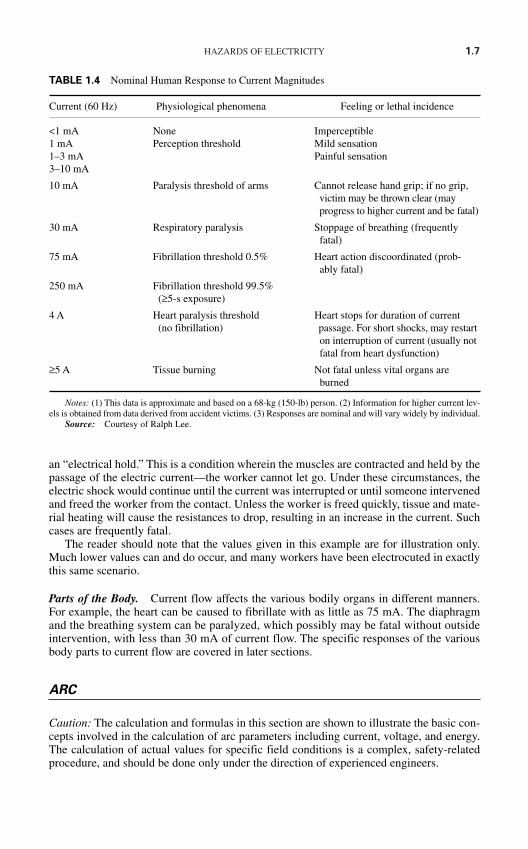
an “electrical hold.” This is a condition wherein the muscles are contracted and held by thepassage of the electric current—the worker cannot let go. Under these circumstances, theelectric shock would continue until the current was interrupted or until someone intervenedand freed the worker from the contact. Unless the worker is freed quickly, tissue and mate-rial heating will cause the resistances to drop, resulting in an increase in the current. Suchcases are frequently fatal.
The reader should note that the values given in this example are for illustration only.Much lower values can and do occur, and many workers have been electrocuted in exactlythis same scenario.
Parts of the Body. Current flow affects the various bodily organs in different manners.For example, the heart can be caused to fibrillate with as little as 75 mA. The diaphragmand the breathing system can be paralyzed, which possibly may be fatal without outsideintervention, with less than 30 mA of current flow. The specific responses of the variousbody parts to current flow are covered in later sections.
ARC
Caution: The calculation and formulas in this section are shown to illustrate the basic con-cepts involved in the calculation of arc parameters including current, voltage, and energy.The calculation of actual values for specific field conditions is a complex, safety-relatedprocedure, and should be done only under the direction of experienced engineers.
TABLE 1.4 Nominal Human Response to Current Magnitudes
Current (60 Hz) Physiological phenomena Feeling or lethal incidence
<1 mA None Imperceptible1 mA Perception threshold Mild sensation1–3 mA Painful sensation3–10 mA
10 mA Paralysis threshold of arms Cannot release hand grip; if no grip,victim may be thrown clear (mayprogress to higher current and be fatal)
30 mA Respiratory paralysis Stoppage of breathing (frequently fatal)
75 mA Fibrillation threshold 0.5% Heart action discoordinated (prob-ably fatal)
250 mA Fibrillation threshold 99.5% (≥5-s exposure)
4 A Heart paralysis threshold Heart stops for duration of current (no fibrillation) passage. For short shocks, may restart
on interruption of current (usually notfatal from heart dysfunction)
≥5 A Tissue burning Not fatal unless vital organs are burned
Notes: (1) This data is approximate and based on a 68-kg (150-lb) person. (2) Information for higher current lev-els is obtained from data derived from accident victims. (3) Responses are nominal and will vary widely by individual.
Source: Courtesy of Ralph Lee.
1.8 CHAPTER ONE
Definition and Description
ANSI/IEEE Std 100-1988 defines arc as: “A discharge of electricity through a gas, nor-mally characterized by a voltage drop in the immediate vicinity of the cathode approxi-mately equal to the ionization potential of the gas.”2
A similar definition, perhaps more useful in the discussion of electrical safety is given in theglossary of this handbook as: “The heat and light energy release that is caused by the electricalbreakdown of and subsequent electrical discharge through an electrical insulator such as air.”
Electric arcing occurs when a substantial amount of electric current flows through what pre-viously had been air. Since air is a poor conductor, most of the current flow is actually occur-ring through the vapor of the arc terminal material and the ionized particles of air. This mixtureof super-heated, ionized materials, through which the arc current flows, is called a plasma.
Arcs can be initiated in several ways:
When the voltage between two points exceeds the dielectric strength of the air. This canhappen when overvoltages due to lightning strikes or switching surges occur.
When the air becomes superheated with the passage of current through some conductor.For example, if a very fine wire is subjected to excessive current, the wire will melt,superheating the air and causing an arc to start.
When two contacts part while carrying a very high current. In this case, the last point ofcontact is superheated and an arc is created because of the inductive flywheel effect.
Electric arcs are extremely hot. Temperatures at the terminal points of the arcs can reachas high as 50,000 kelvin (K). Temperatures away from the terminal points are somewhatcooler but can still reach 20,000 K. Although the specific results of such temperatures willvary depending on things such as distance from the arc, ambient environmental conditions,and arc energy; anecdotal evidence supported by experimental results developed by theInstitute of Electrical and Electronics Engineers (IEEE) clearly shows the following:
The heat energy of an electrical arc can kill and injure personnel at surprisingly largedistances. For example, second-degree burns have been caused on exposed skin at dis-tances of up to 12 feet (ft) or (3.6 meters [m]) and more.
Virtually all types of clothing fibers can be ignited by the temperatures of electrical arcs.Clothing made of non-flame resistant fibers will continue to burn after the arc source hasbeen removed and will continue to cause serious physical trauma. Table 1.5 shows theignition temperature of various fabrics and identifies those that will support combustionafter the arc energy is gone.
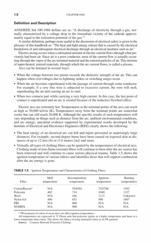
TABLE 1.5 Ignition Temperatures and Characteristics of Clothing Fibers
Melt Decomposition Ignition BurningFiber temperature temperature temperature temperatures
Cotton/Rayon* N/A 554/581 752/788 1562Polyester 482 734 1040 1337Wool N/A 446 1112 UnknownNylon 6,6 490 653 990 1607PBI N/A 860 N/A N/ANOMEX N/A 900 N/A N/A
* FR treatment of cotton of rayon does not affect ignition temperatures.All temperatures are expressed in °F. Please note that polyester ignites at a higher temperature and burns at a
lower temperature than cotton. This shows the fallacy of using untreated cotton as an FR garment.Source: Courtesy Bulwark Protective Clothing.
HAZARDS OF ELECTRICITY 1.9
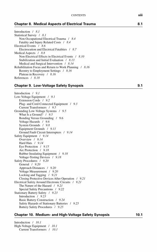
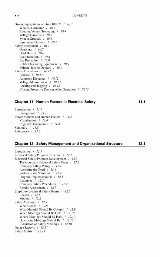
The amount of energy, and therefore heat, in an arc is proportional to the maximum avail-able short circuit volt-amperes in the system at the point of the arc. Calculations by RalphLee indicate that maximum arc energy is equal to one-half the available fault volt-amperesat any given point.3 Later research by Neal, Bingham, and Doughty show that while the max-imum may be 50 percent, the actual value will usually be somewhat different depending onthe degree of distortion of the waveform, the available system voltage, and the actual arcpower factor.4 The same research also shows that enclosing the arc to create a so-called “arcin the box” focuses the incident arc energy and increases its effect by as much as threefold.4,5
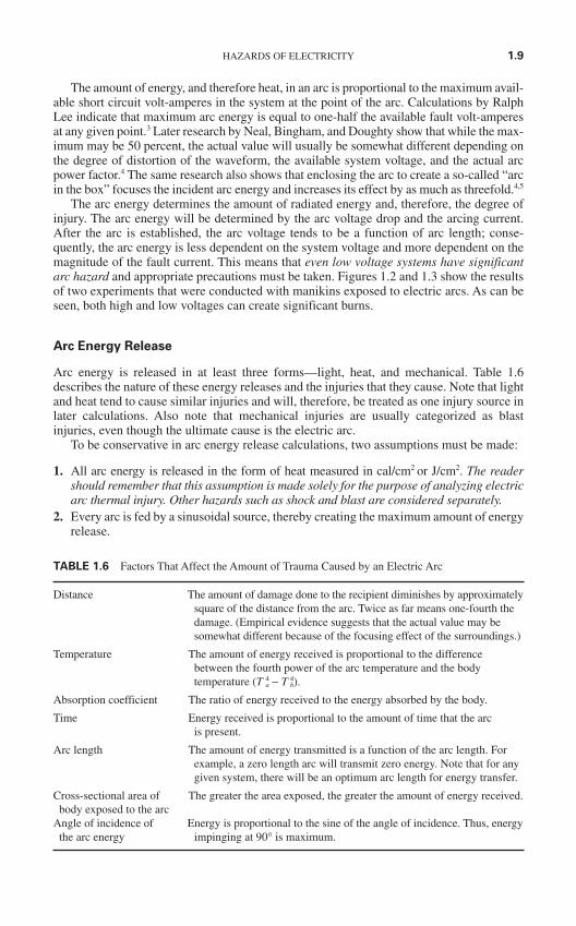
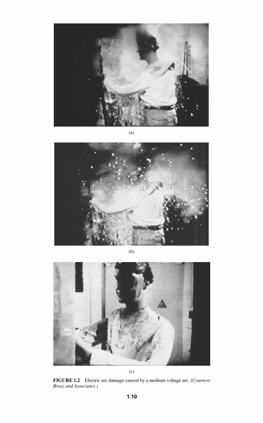
The arc energy determines the amount of radiated energy and, therefore, the degree ofinjury. The arc energy will be determined by the arc voltage drop and the arcing current.After the arc is established, the arc voltage tends to be a function of arc length; conse-quently, the arc energy is less dependent on the system voltage and more dependent on themagnitude of the fault current. This means that even low voltage systems have significantarc hazard and appropriate precautions must be taken. Figures 1.2 and 1.3 show the resultsof two experiments that were conducted with manikins exposed to electric arcs. As can beseen, both high and low voltages can create significant burns.
Arc Energy Release
Arc energy is released in at least three forms—light, heat, and mechanical. Table 1.6describes the nature of these energy releases and the injuries that they cause. Note that lightand heat tend to cause similar injuries and will, therefore, be treated as one injury source inlater calculations. Also note that mechanical injuries are usually categorized as blastinjuries, even though the ultimate cause is the electric arc.
To be conservative in arc energy release calculations, two assumptions must be made:
1. All arc energy is released in the form of heat measured in cal/cm2 or J/cm2. The readershould remember that this assumption is made solely for the purpose of analyzing electricarc thermal injury. Other hazards such as shock and blast are considered separately.
2. Every arc is fed by a sinusoidal source, thereby creating the maximum amount of energyrelease.
TABLE 1.6 Factors That Affect the Amount of Trauma Caused by an Electric Arc
Distance The amount of damage done to the recipient diminishes by approximatelysquare of the distance from the arc. Twice as far means one-fourth thedamage. (Empirical evidence suggests that the actual value may besomewhat different because of the focusing effect of the surroundings.)
Temperature The amount of energy received is proportional to the difference between the fourth power of the arc temperature and the bodytemperature (T a
4 − T b4).
Absorption coefficient The ratio of energy received to the energy absorbed by the body.
Time Energy received is proportional to the amount of time that the arc is present.
Arc length The amount of energy transmitted is a function of the arc length. For example, a zero length arc will transmit zero energy. Note that for anygiven system, there will be an optimum arc length for energy transfer.
Cross-sectional area of The greater the area exposed, the greater the amount of energy received.body exposed to the arc
Angle of incidence of Energy is proportional to the sine of the angle of incidence. Thus, energythe arc energy impinging at 90° is maximum.
(c)
FIGURE 1.2 Electric arc damage caused by a medium voltage arc. (CourtesyBrosz and Associates.)
(b)
1.10
(a)
(c)
FIGURE 1.3 Electric arc damage caused by 240 volt arc. (Courtesy Broszand Associates.)
(b)
(a)
1.11
1.12 CHAPTER ONE
Arc Energy
Several major factors determine the amount of energy created and/or delivered by an elec-tric arc. Table 1.7 lists the major factors and their qualitative effect. The quantitative effectsof electric arc are the subject of many on-going studies.
An individual’s exposure to arc energy is a function of the total arc energy, the distanceof the subject from the arc, and the cross-sectional area of the individual exposed to the arc.
Arc Energy Input
The energy supplied to an electric arc by the electrical system, called the arc input energysmay be calculated using the formula
(1.5)
where Jarc = arc energy, joulesVarc = arc voltage, voltsIarc = arc current, amperes
t = time, seconds
Research has shown that electric arcs are rarely perfect sinusoids; however, the perfectsinusoid creates the greatest arc power. Therefore, Eq. 1.5 can be solved as
Jarc = Varc × Iarc × t × cos (θ) (1.6)
where θ = the angle between current and voltage
Arcing Current. The actual arcing current varies as a function of several variables, andhas been calculated or estimated in different ways. IEEE Standard Std 1584-2002, forexample, gives two equations that may be used to calculate the arcing current.7 Equation1.7 is the formula used for electrical arcs in systems with voltages less than 1000 V andEq. 1.8 is used for systems with voltages equal to or greater than 1000 V.
log10(Ia) = K + 0.662 log10(Ibf) + 0.0966V + 0.000526G
+ 0.5588V log10(Ibf) − 0.00304G log10(Ibf) (1.7)
log10(Ia) = 0.00402 + 0.9831og10(Ibf) (1.8)
J V I dtarc arc arco
t= × × ×∫ cos (θ)
TABLE 1.7 Electrical Arc Injury, Energy Sources
Energy Nature of injuries
Light Principally eye injuries, although severe burns can also be caused if the ultra-violetcomponent is strong enough and lasts long enough.
Heat Severe burns caused by radiation and/or impact of hot objects such as molten metal.
Mechanical Flying objects as well as concussion pressures.
HAZARDS OF ELECTRICITY 1.13
where Ia = arcing current (kA)K = a constant: (−0.153 for open configurations or −0.097 for box configurations)Ibf = the bolted, RMS symmetrical, three-phase fault current (kA)V = system phase-to-phase voltage (kV)G = the gap between the arcing conductors (mm)
Note that these equations are based on a specific model as developed for Std 1584-2002. The model includes the following:
Three-phase voltages in the range of 208 to 15,000 V phase-to-phase Frequencies of 50 or 60 Hz Bolted fault current in the range of 700 to 106,000 A Grounding of all types and ungrounded Equipment enclosures of commonly available sizes Gaps between conductors of 13 to 152 mm Faults involving all three phases
Arcing Voltage
Arc voltage is somewhat more difficult to determine. Values used in power system protec-tion calculations vary from highs of 700 V/ft (214.4 V/m) to as low as 300 V/ft (91.4 V/m).Two things are well understood:
1. Arc voltages start low and tend to rise. Periodically, the arc voltage will drop if the arclasts long enough.6
2. Arc voltage is proportional to arc length. Therefore, from Eq. 1.6, arc power and energyare proportional to arc length.
Modern software programs used to calculate incident arc energy take differentapproaches to determine arc voltage. It should be noted that, at best, arc voltage calculationis only approximate for any given scenario.
Arc Surface Area
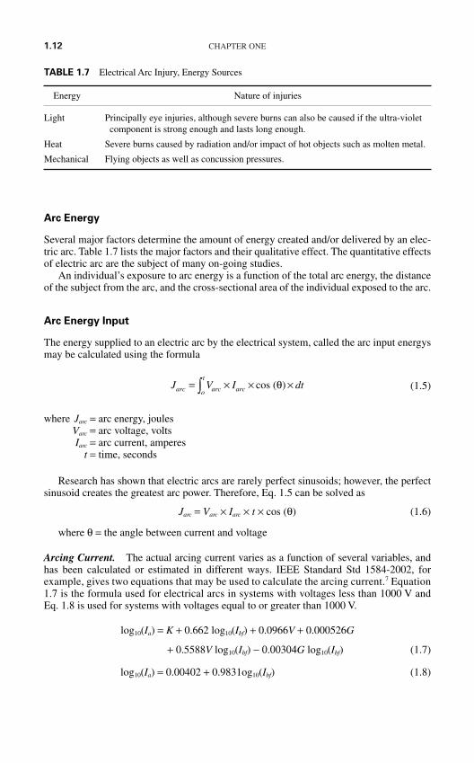
While the actual shape of an electrical arc may vary, all classic, realistic solutions start byassuming that an arc causes an approximately cylindrical plasma cloud with length L andradius r. This cylindrical structure will have a lateral surface area equal to 2πrL. The areaof the ends of the cylinder are ignored in this calculation since they are so small relative tothe side of the arc. To simplify the calculation of energy density, the arc is assumed to forma sphere with a surface area equal to the cylinder, Fig. 1.4. Thus, the arc sphere will have aradius of
(1.9)
where rs = radius of equivalent spherer = radius of arc cylinderL = length of arc
r rLs = 12 2
1.14 CHAPTER ONE
Incident Energy
The single most important of all arc energy calculations is the one that determines theenergy transfer from the arc to the nearby body. This is called the incident energy. Thisinformation can be used to determine the necessary level of protective clothing required,and can also be used in the performance of a risk analysis.
The ultimate measure of tissue injury from electrical arc is the temperature to which thetissue rises during exposure. However, calculation of these temperatures starts with the cal-culation of the amount of energy, or heat flux (measured in calories per square centimeter),delivered to the skin. Many methods have been developed to calculate the incidentenergy—some more conservative than others. The following sections describe some of themethods that have been determined either empirically or theoretically. The reader should beaware that research into these areas is continuing at a frantic pace. Always refer to the mostrecent industry literature for the most up-to-date information.
The Lee Method. Ralph Lee has predicted that the heat energy received by an object (orworker) can be calculated using Eq. 1.10.
(1.10)
where Qo = heat flux received by the object (cal/cm2)Qs = heat flux generated by source (cal/s/cm2)As = surface area of arc spherer = distance from center of source to object (cm)t = length of arc exposure
Using Eq. 1.8 as a starting point, Lee determined that the energy received by the workeris calculated using Eq. 1.11
(1.11)
where E = incident energy in J/cm2
V = system voltage (phase-to-phase)
E VIt
Dbf= ×
2 142 106
2.
QQ A
rto
s s= ×× ×
4 2π
FIGURE 1.4 Arc cylinder and equivalent arc sphere.
HAZARDS OF ELECTRICITY 1.15
t = arcing time (seconds)D = distance from arc point to person or object (mm)Ibf = bolted fault current (kA)
Other Early Research. Research by Bingham and others4,5,7 has yielded a slightly differ-ent result based primarily on empirical results. Using an experimental setup,7 the researchersmeasured energy received from an electric arc at various distances. The arc was createdusing a 600-V source, and different configurations were used to simulate a completelyopen-air arc versus the so-called “arc-in-a-box.” Using these experiments, they developedtwo equations to model the amount of energy received.
EMA = 5271DA−1.9593tA(0.0016F2 − 0.0076F + 0.8938) (1.12)
EMB = 1038.7DB−1.4738tB(0.0093F2 − 0.3453F + 5.975) (1.13)
where EMA = maximum open-arc incident energy (cal/cm2)EMB = maximum arc-in-a-box incident energy (cal/cm2)
D = distance from the arc electrodes in inches (D ≥ 18 in)F = bolted fault current available in kA (16 to 50 kA range)tA = duration of the open-air arc (seconds)tB = duration of the arc-in-a-boc (seconds)
Note that these equations were developed with three constraints:
1. System voltage = 600 V
2. System available fault current F − 16,000 A < F < 50,000 A
3. Electrode distance D ≥ 18 in (45.72 cm)
Using the model previously described (see “Arcing Current”), the IEEE Std 1584-2002calculates incident energy by first calculating the normalized incident energy. The normal-ized energy is calculated for an arc time of 0.2 seconds and a distance of 610 mm. Theempirically developed formula for this calculation is shown in Eq. 1.14.
log10(En) = K1 + K2 + 1.081[log10(Ia)] + 0.0011G (1.14)
where Ia = arc current calculated from Eq. 1.7En = incident energy (J/cm2) normalized for time and distanceK1 = constant and is equal to −0.792 for open configurations and −0.555 for enclosed
configurationsK2 = constant and is equal to 0 for ungrounded and high resistance systems and
−0.113 for grounded systemsG = gap between conductors (mm)
After the log10 En is calculated from Eq. 1.14, Eq. 1.15 is used to calculate En, andEq. 1.16 is used to calculate the actual incident energy.
(1.15)
(1.16)
where E = incident energy (J/cm2)Cf = calculation factor equal to 1.0 for voltages above 1 kV and 1.5 for voltage equal
to or below 1 kV.
E C E tDf n
x
x=
4 184
0 2610.
.
EnEn= 10 10log
1.16 CHAPTER ONE
En = normalized incident energy calculated from Eqs. 1.14 and 1.15t = arcing time in seconds
D = distance from the arc point to the exposed worker (mm)x = distance exponent whose value is dependent on voltage. (See IEEE Std 1584-
2002, Table 4 for values of x.)
Extensive research continues to be performed on the subject of incident arc energy.Practical applications used in the selection of protective equipment are covered in detailin Chap. 2.
Arc Burns
Arc burns are thermal in nature and, therefore, fall into one of the three classical categories:
First-degree burns. First-degree burning causes painful trauma to the outer layers of theskin. Little permanent damage results from a first-degree burn because all the growthareas survive. Healing is usually prompt and leaves no scarring.
Second-degree burns. Second-degree burns result in relatively severe tissue damageand blistering. If the burn is to the skin, the entire outer layer will be destroyed. Healingoccurs from the sweat glands and/or hair follicles.
Third-degree burns. Third-degree burns to the skin result in complete destruction of thegrowth centers. If the burn is small, healing may occur from the edges of the damagedarea; however, extensive third-degree burns require skin grafting.
Refer to Chap. 8 for more detailed coverage of electrical arc trauma.
BLAST
When an electric arc occurs, it superheats the air instantaneously. This causes a rapidexpansion of the air with a wavefront that can reach pressures of 100 to 200 lb per squarefoot (lb/ft2)(4.79 to 9.58 kPa). Such pressure is sufficient to explode switchgear, turn sheetmetal into shrapnel, turn hardware into bullets, push over concrete walls, and propel moltenmetal at extremely high velocities.
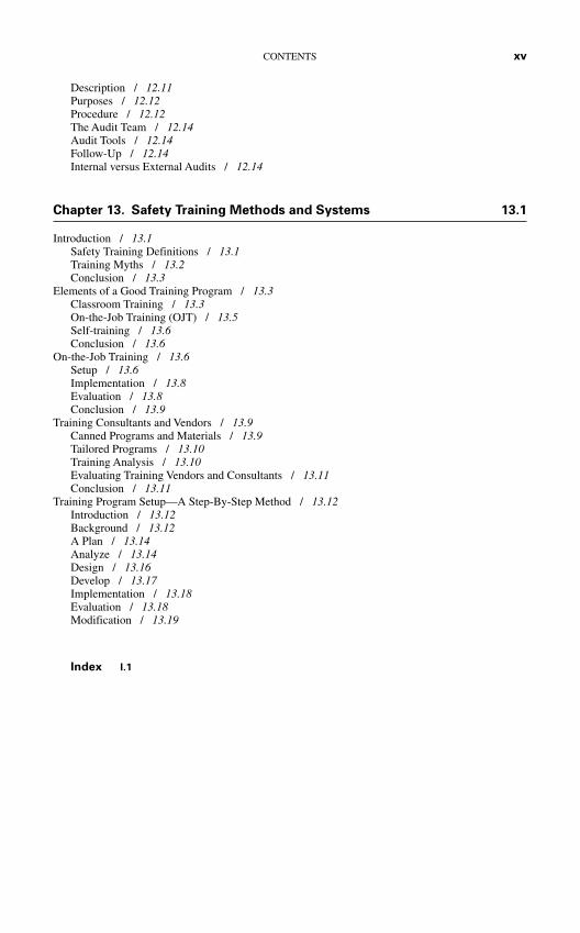
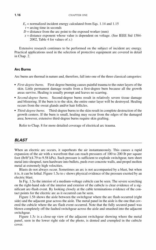
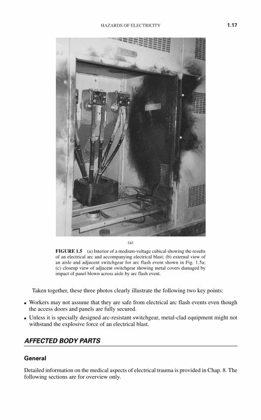
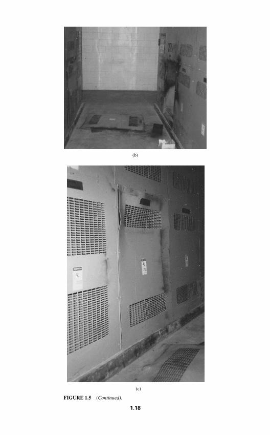
Blasts do not always occur. Sometimes an arc is not accompanied by a blast, but whenit is, it can be lethal. Figure 1.5a to c shows physical evidence of the pressure exerted by anelectric blast.
In Fig. 1.5a the interior of a medium-voltage cubicle can be seen. The severe scorchingon the right-hand side of the interior and exterior of the cubicle is clear evidence of a sig-nificant arc-flash event. By looking closely at the cable terminations evidence of the con-tact points for the electric arc as it occurred can be seen.
Figure 1.5b shows the aisle between the switchgear where the arc flash occurred (rightside) and the adjacent gear across the aisle. The metal panel in the aisle is the one that cov-ered the cubicle where the arc flash event occurred. Note that the fully secured panel wasblown completely off the faulted switchgear across the aisle and smashed into the adjacentswitchgear.
Figure 1.5c is a close-up view of the adjacent switchgear showing where the metalpanel, seen in the lower right side of the photo, is dented and crumpled in the cubiclecover.
HAZARDS OF ELECTRICITY 1.17
Taken together, these three photos clearly illustrate the following two key points:
Workers may not assume that they are safe from electrical arc flash events even thoughthe access doors and panels are fully secured.
Unless it is specially designed arc-resistant switchgear, metal-clad equipment might notwithstand the explosive force of an electrical blast.
AFFECTED BODY PARTS
General
Detailed information on the medical aspects of electrical trauma is provided in Chap. 8. Thefollowing sections are for overview only.
(a)
FIGURE 1.5 (a) Interior of a medium-voltage cubical showing the resultsof an electrical arc and accompanying electrical blast; (b) external view ofan aisle and adjucent switchgear for arc flash event shown in Fig. 1.5a;(c) closeup view of adjucent switchgear showing metal covers damaged byimpact of panel blown across aisle by arc flash event.
(b)
(c)
FIGURE 1.5 (Continued).
1.18
HAZARDS OF ELECTRICITY 1.19
Skin
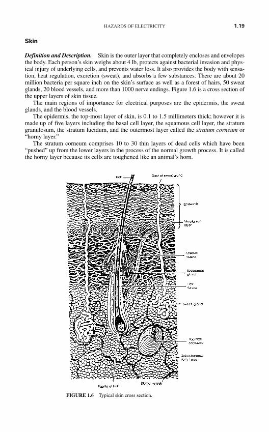
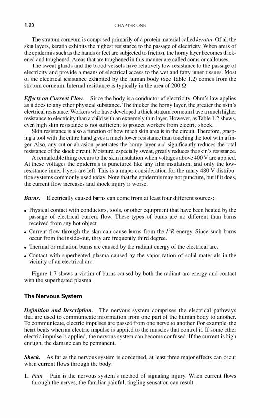
Definition and Description. Skin is the outer layer that completely encloses and envelopesthe body. Each person’s skin weighs about 4 lb, protects against bacterial invasion and phys-ical injury of underlying cells, and prevents water loss. It also provides the body with sensa-tion, heat regulation, excretion (sweat), and absorbs a few substances. There are about 20million bacteria per square inch on the skin’s surface as well as a forest of hairs, 50 sweatglands, 20 blood vessels, and more than 1000 nerve endings. Figure 1.6 is a cross section ofthe upper layers of skin tissue.
The main regions of importance for electrical purposes are the epidermis, the sweatglands, and the blood vessels.
The epidermis, the top-most layer of skin, is 0.1 to 1.5 millimeters thick; however it ismade up of five layers including the basal cell layer, the squamous cell layer, the stratumgranulosum, the stratum lucidum, and the outermost layer called the stratum corneum or“horny layer.”
The stratum corneum comprises 10 to 30 thin layers of dead cells which have been“pushed” up from the lower layers in the process of the normal growth process. It is calledthe horny layer because its cells are toughened like an animal’s horn.
FIGURE 1.6 Typical skin cross section.
1.20 CHAPTER ONE
The stratum corneum is composed primarily of a protein material called keratin. Of all theskin layers, keratin exhibits the highest resistance to the passage of electricity. When areas ofthe epidermis such as the hands or feet are subjected to friction, the horny layer becomes thick-ened and toughened. Areas that are toughened in this manner are called corns or callouses.
The sweat glands and the blood vessels have relatively low resistance to the passage ofelectricity and provide a means of electrical access to the wet and fatty inner tissues. Mostof the electrical resistance exhibited by the human body (See Table 1.2) comes from thestratum corneum. Internal resistance is typically in the area of 200 Ω.
Effects on Current Flow. Since the body is a conductor of electricity, Ohm’s law appliesas it does to any other physical substance. The thicker the horny layer, the greater the skin’selectrical resistance. Workers who have developed a thick stratum corneum have a much higherresistance to electricity than a child with an extremely thin layer. However, as Table 1.2 shows,even high skin resistance is not sufficient to protect workers from electric shock.
Skin resistance is also a function of how much skin area is in the circuit. Therefore, grasp-ing a tool with the entire hand gives a much lower resistance than touching the tool with a fin-ger. Also, any cut or abrasion penetrates the horny layer and significantly reduces the totalresistance of the shock circuit. Moisture, especially sweat, greatly reduces the skin’s resistance.
A remarkable thing occurs to the skin insulation when voltages above 400 V are applied.At these voltages the epidermis is punctured like any film insulation, and only the low-resistance inner layers are left. This is a major consideration for the many 480 V distribu-tion systems commonly used today. Note that the epidermis may not puncture, but if it does,the current flow increases and shock injury is worse.
Burns. Electrically caused burns can come from at least four different sources:
Physical contact with conductors, tools, or other equipment that have been heated by thepassage of electrical current flow. These types of burns are no different than burnsreceived from any hot object.
Current flow through the skin can cause burns from the I 2R energy. Since such burnsoccur from the inside-out, they are frequently third degree.
Thermal or radiation burns are caused by the radiant energy of the electrical arc.
Contact with superheated plasma caused by the vaporization of solid materials in thevicinity of an electrical arc.
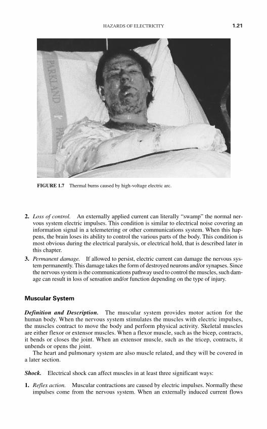
Figure 1.7 shows a victim of burns caused by both the radiant arc energy and contactwith the superheated plasma.
The Nervous System
Definition and Description. The nervous system comprises the electrical pathwaysthat are used to communicate information from one part of the human body to another.To communicate, electric impulses are passed from one nerve to another. For example, theheart beats when an electric impulse is applied to the muscles that control it. If some otherelectric impulse is applied, the nervous system can become confused. If the current is highenough, the damage can be permanent.
Shock. As far as the nervous system is concerned, at least three major effects can occurwhen current flows through the body:
1. Pain. Pain is the nervous system’s method of signaling injury. When current flowsthrough the nerves, the familiar painful, tingling sensation can result.
HAZARDS OF ELECTRICITY 1.21
2. Loss of control. An externally applied current can literally “swamp” the normal ner-vous system electric impulses. This condition is similar to electrical noise covering aninformation signal in a telemetering or other communications system. When this hap-pens, the brain loses its ability to control the various parts of the body. This condition ismost obvious during the electrical paralysis, or electrical hold, that is described later inthis chapter.
3. Permanent damage. If allowed to persist, electric current can damage the nervous sys-tem permanently. This damage takes the form of destroyed neurons and/or synapses. Sincethe nervous system is the communications pathway used to control the muscles, such dam-age can result in loss of sensation and/or function depending on the type of injury.
Muscular System
Definition and Description. The muscular system provides motor action for thehuman body. When the nervous system stimulates the muscles with electric impulses,the muscles contract to move the body and perform physical activity. Skeletal musclesare either flexor or extensor muscles. When a flexor muscle, such as the bicep, contracts,it bends or closes the joint. When an extensor muscle, such as the tricep, contracts, itunbends or opens the joint.
The heart and pulmonary system are also muscle related, and they will be covered ina later section.
Shock. Electrical shock can affect muscles in at least three significant ways:
1. Reflex action. Muscular contractions are caused by electric impulses. Normally theseimpulses come from the nervous system. When an externally induced current flows
FIGURE 1.7 Thermal burns caused by high-voltage electric arc.
1.22 CHAPTER ONE
through a muscle, it can cause the muscle to contract, perhaps violently. This contrac-tion can cause workers to fall off ladders or smash into steel doors or other structures.
2. Electrical paralysis. Current magnitudes in excess of 10 mA may be sufficient toblock the nervous system signals to the muscular system. Thus, when such an externalcurrent is flowing through the body, the victim may be unable to control his or her mus-cles. This means that the victim cannot let go—he or she is caught in an electrical hold.As the current continues, the heating and burning action can lower the path resistanceand cause an increase in the current. If the current is not cut off or if the victim is notfreed from the circuit, death will occur.
3. Permanent damage. If the current is high enough, the muscle tissue can be destroyedby burning. Currents of even less than 5 A will cause tissue destruction if they last longenough. Because such burning destroys the growth areas in tissue, the damage can beextremely slow to heal. Physical therapy and other extraordinary methods may berequired to restore muscular function.
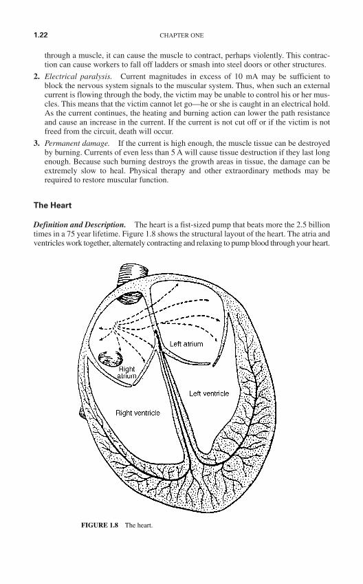
The Heart
Definition and Description. The heart is a fist-sized pump that beats more the 2.5 billiontimes in a 75 year lifetime. Figure 1.8 shows the structural layout of the heart. The atria andventricles work together, alternately contracting and relaxing to pump blood through your heart.
FIGURE 1.8 The heart.
HAZARDS OF ELECTRICITY 1.23
The electrical system of your heart is the power source that makes this possible. Normally a heartbeat starts in the sinus node, travels at approximately 7 ft/s (2.1 m/s) through the AV node, “HISbundle,” and right and left bundle branches. The resulting contraction sends blood flowing fromthe heart.
This sequence occurs with every beat (usually 60 to 100 times per minute). If the path isinterrupted for any reason, even for a few minutes, changes in the heart rate and rhythm occurthat can be fatal.
Shock. When the heart's electrical system is disturbed for any reason, such as an outside cur-rent from an electric shock, changes in the heart’s rate and rhythm occur. Such disruptions resultin a large percentage of heart deaths.
The electric impulses in the heart must be coordinated to give a smooth, rhythmic beat. Anoutside current of as little as 60 to 75 mA can disturb the nerve impulses so that there is no longera smooth, timed heartbeat. Instead the heart fibrillates—that is, it beats in a rapid, uncoordinatedmanner. When a heart is fibrillating, it flutters uselessly. Prolonged exposure to an outside cur-rent exceeding 75 mA is likely to result in death.
Like any muscle, the heart will become paralyzed if the current flowing through it is of suf-ficient magnitude. Oddly, paralysis of the heart is not often fatal if the current is removed quicklyenough. In fact, such paralysis is used to an advantage in defibrillators. A defibrillator inten-tionally applies heart-paralyzing current. When the current is removed, the heart is in a relaxedstate ready for the next signal. Frequently the heart restarts.
Burns. Any internal organ, such as the heart, can be burned by current flows in excess of5 A. Such burns are often fatal.
The Pulmonary System
Definition and Description. With the exception of the heart, the pulmonary system is themost critical to human life. If breathing stops, which can happen with as little as 30 mA, allother functions cease shortly thereafter. When the lower diaphragm moves down, it createsa partial vacuum in the chest chamber. This in turn draws air into the sacs in the lungs. Theoxygen is then passed to the bloodstream through the tiny capillaries. At the same time, car-bon dioxide is returned to the air in the lungs. When the lower diaphragm moves up, the airis forced out of the lungs, thus completing the breathing cycle.
Shock. Current flow through the midsection of the body can disrupt the nervous systemimpulses which regulate the breathing function. This disruption can take the form of irregular,sporadic breathing, or—if the current flow is sufficient—the pulmonary system may be par-alyzed altogether. When such stoppage occurs, first aid is often required.
SUMMARY OF CAUSES—INJURY AND DEATH
Shock Effect
Table 1.4 summarizes the effects that electric shocks of varying amounts of current willhave on a 68-kg (150-lb) person. Note that these effects are only approximate and varybetween individuals.
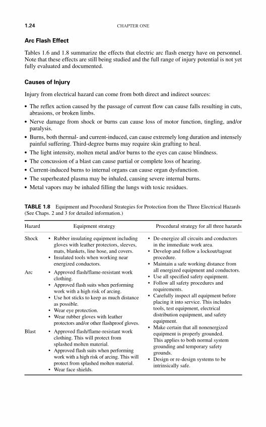
1.24 CHAPTER ONE
Arc Flash Effect
Tables 1.6 and 1.8 summarize the effects that electric arc flash energy have on personnel.Note that these effects are still being studied and the full range of injury potential is not yetfully evaluated and documented.
Causes of Injury
Injury from electrical hazard can come from both direct and indirect sources:
The reflex action caused by the passage of current flow can cause falls resulting in cuts,abrasions, or broken limbs.
Nerve damage from shock or burns can cause loss of motor function, tingling, and/orparalysis.
Burns, both thermal- and current-induced, can cause extremely long duration and intenselypainful suffering. Third-degree burns may require skin grafting to heal.
The light intensity, molten metal and/or burns to the eyes can cause blindness. The concussion of a blast can cause partial or complete loss of hearing. Current-induced burns to internal organs can cause organ dysfunction. The superheated plasma may be inhaled, causing severe internal burns. Metal vapors may be inhaled filling the lungs with toxic residues.
Hazard Equipment strategy Procedural strategy for all three hazards
Shock
Arc
Blast
• De-energize all circuits and conductorsin the immediate work area.
• Develop and follow a lockout/tagoutprocedure.
• Maintain a safe working distance fromall energized equipment and conductors.
• Use all specified safety equipment.• Follow all safety procedures and
requirements.• Carefully inspect all equipment before
placing it into service. This includestools, test equipment, electricaldistribution equipment, and safetyequipment.
• Make certain that all nonenergizedequipment is properly grounded. This applies to both normal systemgrounding and temporary safetygrounds.
• Design or re-design systems to beintrinsically safe.
• Rubber insulating equipment includinggloves with leather protectors, sleeves,mats, blankets, line hose, and covers.
• Insulated tools when working nearenergized conductors.
• Approved flash/flame-resistant workclothing.
• Approved flash suits when performingwork with a high risk of arcing.
• Use hot sticks to keep as much distanceas possible.
• Wear eye protection.• Wear rubber gloves with leather
protectors and/or other flashproof gloves.
• Approved flash/flame-resistant workclothing. This will protect fromsplashed molten material.
• Approved flash suits when performingwork with a high risk of arcing. This willprotect from splashed molten material.
• Wear face shields.
TABLE 1.8 Equipment and Procedural Strategies for Protection from the Three Electrical Hazards(See Chaps. 2 and 3 for detailed information.)
HAZARDS OF ELECTRICITY 1.25
Causes of Death
If the electrical injury is severe enough, death can result.
An electric shock–induced fall can cause fatal physical injuries. When the skin is severely burnt, large quantities of liquid are brought to the burnt areas
to aid in the healing process. This creates a stress on the renal system and could result inkidney failure.
Severe trauma from massive burns can cause a general systemic failure. Burnt internal organs can shut down—causing death. Thus, the more critical the organ
that is burnt, the higher the possibility of death. The pressure front from the blast can cause severe injury to the lungs, called blast-lung,
resulting in death. Heart failure can result from fibrillation and/or paralysis.
PROTECTIVE STRATEGIES
The types of strategies that may be employed to protect from each of the three electricalhazards are remarkably similar. Table 1.8 summarizes the types of protective strategies thatmay be used. Note that the information given in Table 1.8 is general. Specific equipmentand procedures are covered in Chaps. 2 and 3.
Be aware that any given strategy may not be applicable in a given situation. Forexample,
When troubleshooting equipment, de-energization may not be possible. De-energization may create an additional, unacceptable hazard. For example, if de-
energization shuts down ventilation equipment in a hazardous area, workers may opt forworking with energized equipment.
Shutdown of an entire continuous process plan to work on or around one small auxiliarycircuit may not be economically feasible.
If electrical equipment cannot be de-energized, a hierarchy of electrical safe work prac-tices and procedures must be implemented as follows:
Document the reason(s) for having to work on or near energized electrical conductors orcircuit parts. Identify that de-energizing is infeasible.
Obtain responsible manager’s (employer’s designated person) signature, verifyingknowledge and recognizing the need to work on or near exposed energized electrical con-ductors or circuit parts.
Perform a job briefing that includes a hazard-risk analysis. Prepare and follow a documented plan of work processes and tasks. If worker(s) must enter closer to the potential arc source(s) than the flash protection
boundary, then ensure that the worker is a “qualified person” and is wearing appro-priate personal protective clothing (PPC) and using other personal protective equip-ment (PPE).
REFERENCES
1. Raphael C. Lee, “Injury by Electrical Forces: Pathophysiology, Manifestations and Therapy,”Current Problems in Surgery, vol. 34, no. 9, 1997.
2. Institute of Electrical and Electronics Engineers (IEEE), Standard Dictionary of Electrical andElectronics Terms, ANSI/IEEE Std 100-1988, p. 240.
3. Ralph H. Lee, “The Other Electrical Hazard: Electric Arc Blast Burns,” IEEE Trans. IndustrialApplications, vol. 1A-18, no. 3, 1982, p. 246.
4. Thomas E. Neal, Allen H. Bingham, and Richard I. Doughty, “Protective Clothing Guidelines forElectric Arc Exposure,” IEEE Paper PCIC-96-34 presented at the Petroleum Chemical IndustryConference in Philadelphia, 1996.
5. Richard I. Doughty, Thomas E. Neal, Terrence A. Dear, and Allen H. Bingham, “Testing Update onProtective Clothing & Equipment for Electric Arc Exposure,” IEEE Paper PCIC-97-35, 1997.
6. J. Lewis Blackburn, Protective Relaying Principles and Applications, 2nd ed., Marcel Dekker, NewYork, 1998.
7. Richard L. Doughty, Thomas E. Neal, and H. Landis Floyd, “Predicting Incident Energy to BetterManage the Electric Arc Hazard on 600-V Power Distribution Systems,” IEEE Paper.
8. Institute of Electrical and Electronic Engineers (IEEE), IEEE Guide for Performing Arc-FlashCalculations, IEEE Std 1584–2002.
1.26 CHAPTER ONE
CHAPTER 2ELECTRICAL SAFETY
EQUIPMENT
INTRODUCTION
The safety aspects of any job or procedure are greatly enhanced by the use of proper toolsmeters, apparel, and other such equipment. This chapter outlines the construction and useof a variety of electrical safety equipment. Some of the equipment is used to actually per-form work—items such as insulated tools or voltage-measuring devices fall into this cate-gory. Other safety products are used strictly to protect the worker, for example, flash suitsand rubber goods.
Each specific piece of safety equipment is used to protect the worker from one or moreof the three electrical safety hazards, and each piece of equipment should be employedwhen performing various types of jobs in the electric power system.
Always be certain that the clothing or apparel and the meters or tools you are using aredesigned and tested to match or exceed the incident energy level, and the voltage level forthe application to which you will be exposed.
GLOSSARY
ATPV (Arc Thermal “. . .the incident energy on a fabric or material that results in Performance Value) sufficient heat transfer through the fabric or material to cause
the onset of a second-degree burn based on the Stoll curve.”1
EBT (Energy “the average of the five highest incident energy exposure valuesBreak-Through) below the Stoll curve where the specimens do not exhibit
breakopen.”1
Flame Resistant A fabric or material that burns very slowly and self-extinguishesupon the removal of an external flame.
Flame retardant A chemical applied to or incorporated into a fabric at the time of production, which significantly reduces a fabric’s flammability.
Flammable Easily ignited and capable of burning rapidly.
Flash Boundary The radial distance from an energized conductor at which the heatenergy will equal 1.2 cal/cm2 in the event that the worstcase arc-flash event occurs.
Stoll Curve A tabular or graphical relationship which quantitatively describes the relationship between heat energy and human skin.2
2.1
Copyright © 2006 by The McGraw-Hill Companies, Inc. Click here for terms of use.
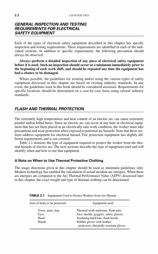
2.2 CHAPTER TWO
GENERAL INSPECTION AND TESTINGREQUIREMENTS FOR ELECTRICAL SAFETY EQUIPMENT
Each of the types of electrical safety equipment described in this chapter has specificinspection and testing requirements. These requirements are identified in each of the indi-vidual sections. In addition to specific requirements, the following precaution shouldalways be observed:
Always perform a detailed inspection of any piece of electrical safety equipmentbefore it is used. Such an inspection should occur at a minimum immediately prior tothe beginning of each work shift, and should be repeated any time the equipment hashad a chance to be damaged.
Where possible, the guidelines for wearing and/or using the various types of safetyequipment discussed in this chapter are based on existing industry standards. In anyevent, the guidelines used in this book should be considered minimum. Requirements forspecific locations should be determined on a case-by-case basis using current industrystandards.
FLASH AND THERMAL PROTECTION
The extremely high temperatures and heat content of an electric arc can cause extremelypainful and/or lethal burns. Since an electric arc can occur at any time in electrical equip-ment that has not been placed in an electrically safe work condition, the worker must takeprecautions and wear protection when exposed to potential arc hazards. Note that these sec-tions address equipment for electrical hazard. Fire protection equipment has slightly dif-ferent requirements and is not covered.
Table 2.1 itemizes the type of equipment required to protect the worker from the ther-mal hazards of electric arc. The next sections describe the type of equipment used and willidentify when and how to use that equipment.
A Note on When to Use Thermal Protective Clothing
The usage directions given in this chapter should be used as minimum guidelines only.Modern technology has enabled the calculation of actual incident arc energies. When thesearc energies are compared to the Arc Thermal Performance Value (ATPV) discussed laterin this chapter, the exact weight and type of thermal clothing can be determined.
Area of body to be protected Equipment used
Torso, arms, legs Thermal work uniforms, flash suitsEyes Face shields, goggles, safety glassesHead Insulating hard hats, flash hoodsHands Rubber gloves with leather
protectors, thermally resistant gloves
TABLE 2.1 Equipment Used to Protect Workers from Arc Hazard
If workers are required to place any part of their body within the flash boundary distanceof an energized electrical component, they must wear thermal protective clothing with anATPV or EBT equal to or greater than the amount of arc energy to which they might beexposed. Chapter 3 of this handbook provides specific methods for these calculations. TheATPV or EBT for any given material is calculated using the procedures defined in ASTMStandard F 1959/F 1959M.1
Thermal Performance Evaluation
Flame Resistance (FR). Virtually all clothing will ignite when exposed to a sufficientheat source. When the heat source is removed, normal clothing will continue to burn.Flame-resistant clothing may burn and char when it is exposed to a heat source, but it willnot continue to burn after the heat source is removed.
The most common test for flame resistance is defined in Method 5903.1 of Federal TestStandard 191A (Flame Resistance of Cloth: Vertical). This test suspends a 12-inch-longspecimen of fabric vertically in a holder. The fabric is enclosed and subjected to a controlledflame on the bottom edge of the fabric for 12 seconds. Table 2.2 lists the three sets of datathat are recorded in this test.
Note that the results are gathered after the flame source has been removed. Note also thatthe afterglow is not included in most of the industry standards that reference this method.
Arc Thermal Performance Value (ATPV). Research by Stoll & Chianta2 developed acurve (the so-called Stoll curve) for human tolerance to heat. The curve is based on theminimum incident heat energy (in kJ/m2 or cal/cm2) that will cause a second-degree burnon human skin. Modern standards that define the level of thermal protection required arebased on the Stoll curve. That is, clothing must be worn that will limit the degree of injuryto a second-degree burn. This rating is called the Arc Thermal Performance Value(ATPV).
Energy Break-Through (EBT ). Some types of flame resistant materials become brittlewhen exposed to very high temperatures. The combination of the brittleness and the con-cussion from the electrical blast can cause the material to fail and break open. ASTM hasdefined this value as the average of the five highest incident energy exposure values belowthe Stoll curve where the specimens do not exhibit breakopen.
Since the EBT is defined for values below the Stoll curve, garments made from such mate-rials can be safely used where exposures will be less than the energy break-through level.
ELECTRICAL SAFETY EQUIPMENT 2.3
TABLE 2.2 Test Data Drawn from Method 5903.1 of Federal Test Standard 191A
Test result measured Description
Afterflame The number of seconds (in tenths) during which there is a visible flame remaining on the fabric
Afterglow The number of seconds (in tenths) during which there is a visible glowremaining on the fabric
Char length The length of the fabric in tenths of an inch destroyed by the flame that willreadily tear by application of a standard weight
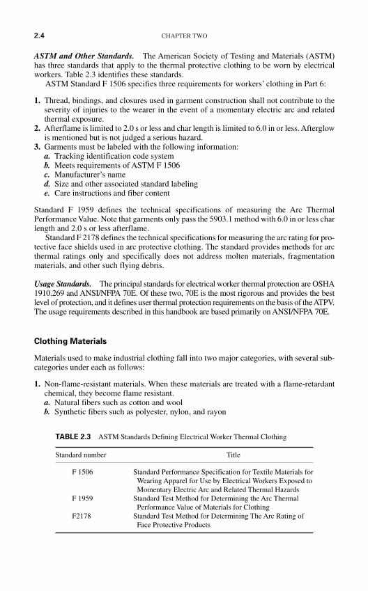
2.4 CHAPTER TWO
ASTM and Other Standards. The American Society of Testing and Materials (ASTM)has three standards that apply to the thermal protective clothing to be worn by electricalworkers. Table 2.3 identifies these standards.
ASTM Standard F 1506 specifies three requirements for workers’ clothing in Part 6:
1. Thread, bindings, and closures used in garment construction shall not contribute to theseverity of injuries to the wearer in the event of a momentary electric arc and relatedthermal exposure.
2. Afterflame is limited to 2.0 s or less and char length is limited to 6.0 in or less. Afterglowis mentioned but is not judged a serious hazard.
3. Garments must be labeled with the following information:a. Tracking identification code systemb. Meets requirements of ASTM F 1506c. Manufacturer’s named. Size and other associated standard labelinge. Care instructions and fiber content
Standard F 1959 defines the technical specifications of measuring the Arc ThermalPerformance Value. Note that garments only pass the 5903.1 method with 6.0 in or less charlength and 2.0 s or less afterflame.
Standard F 2178 defines the technical specifications for measuring the arc rating for pro-tective face shields used in arc protective clothing. The standard provides methods for arcthermal ratings only and specifically does not address molten materials, fragmentationmaterials, and other such flying debris.
Usage Standards. The principal standards for electrical worker thermal protection are OSHA1910.269 and ANSI/NFPA 70E. Of these two, 70E is the most rigorous and provides the bestlevel of protection, and it defines user thermal protection requirements on the basis of the ATPV.The usage requirements described in this handbook are based primarily on ANSI/NFPA 70E.
Clothing Materials
Materials used to make industrial clothing fall into two major categories, with several sub-categories under each as follows:
1. Non-flame-resistant materials. When these materials are treated with a flame-retardantchemical, they become flame resistant.a. Natural fibers such as cotton and woolb. Synthetic fibers such as polyester, nylon, and rayon
TABLE 2.3 ASTM Standards Defining Electrical Worker Thermal Clothing
Standard number Title
F 1506 Standard Performance Specification for Textile Materials for Wearing Apparel for Use by Electrical Workers Exposed to Momentary Electric Arc and Related Thermal Hazards
F 1959 Standard Test Method for Determining the Arc Thermal Performance Value of Materials for Clothing
F2178 Standard Test Method for Determining The Arc Rating of Face Protective Products
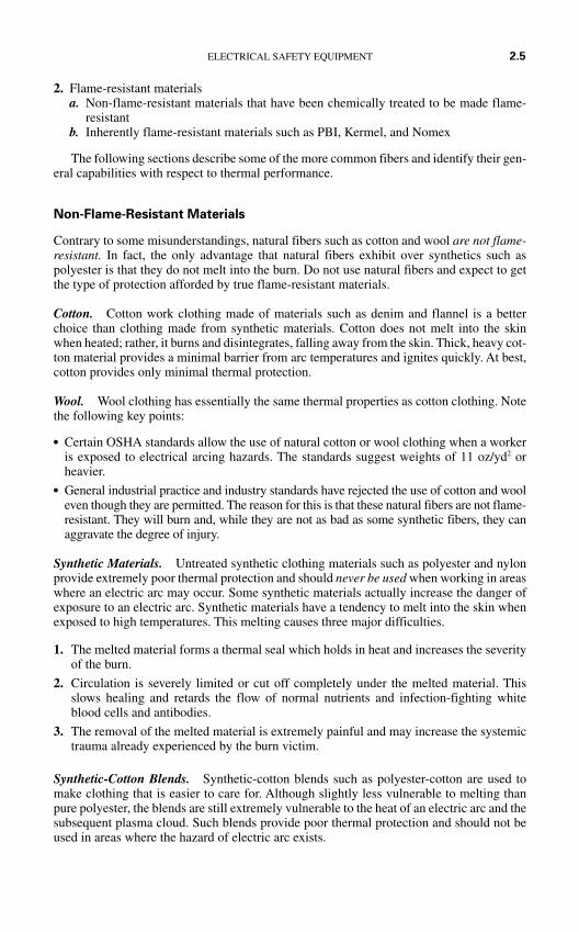
2. Flame-resistant materialsa. Non-flame-resistant materials that have been chemically treated to be made flame-
resistantb. Inherently flame-resistant materials such as PBI, Kermel, and Nomex
The following sections describe some of the more common fibers and identify their gen-eral capabilities with respect to thermal performance.
Non-Flame-Resistant Materials
Contrary to some misunderstandings, natural fibers such as cotton and wool are not flame-resistant. In fact, the only advantage that natural fibers exhibit over synthetics such aspolyester is that they do not melt into the burn. Do not use natural fibers and expect to getthe type of protection afforded by true flame-resistant materials.
Cotton. Cotton work clothing made of materials such as denim and flannel is a betterchoice than clothing made from synthetic materials. Cotton does not melt into the skinwhen heated; rather, it burns and disintegrates, falling away from the skin. Thick, heavy cot-ton material provides a minimal barrier from arc temperatures and ignites quickly. At best,cotton provides only minimal thermal protection.
Wool. Wool clothing has essentially the same thermal properties as cotton clothing. Notethe following key points:
Certain OSHA standards allow the use of natural cotton or wool clothing when a workeris exposed to electrical arcing hazards. The standards suggest weights of 11 oz/yd2 orheavier.
General industrial practice and industry standards have rejected the use of cotton and wooleven though they are permitted. The reason for this is that these natural fibers are not flame-resistant. They will burn and, while they are not as bad as some synthetic fibers, they canaggravate the degree of injury.
Synthetic Materials. Untreated synthetic clothing materials such as polyester and nylonprovide extremely poor thermal protection and should never be used when working in areaswhere an electric arc may occur. Some synthetic materials actually increase the danger ofexposure to an electric arc. Synthetic materials have a tendency to melt into the skin whenexposed to high temperatures. This melting causes three major difficulties.
1. The melted material forms a thermal seal which holds in heat and increases the severityof the burn.
2. Circulation is severely limited or cut off completely under the melted material. Thisslows healing and retards the flow of normal nutrients and infection-fighting whiteblood cells and antibodies.
3. The removal of the melted material is extremely painful and may increase the systemictrauma already experienced by the burn victim.
Synthetic-Cotton Blends. Synthetic-cotton blends such as polyester-cotton are used tomake clothing that is easier to care for. Although slightly less vulnerable to melting thanpure polyester, the blends are still extremely vulnerable to the heat of an electric arc and thesubsequent plasma cloud. Such blends provide poor thermal protection and should not beused in areas where the hazard of electric arc exists.
ELECTRICAL SAFETY EQUIPMENT 2.5
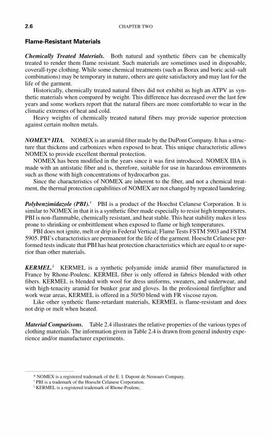
Flame-Resistant Materials
Chemically Treated Materials. Both natural and synthetic fibers can be chemicallytreated to render them flame resistant. Such materials are sometimes used in disposable,coverall-type clothing. While some chemical treatments (such as Borax and boric acid–saltcombinations) may be temporary in nature, others are quite satisfactory and may last for thelife of the garment.
Historically, chemically treated natural fibers did not exhibit as high an ATPV as syn-thetic materials when compared by weight. This difference has decreased over the last fewyears and some workers report that the natural fibers are more comfortable to wear in theclimatic extremes of heat and cold.
Heavy weights of chemically treated natural fibers may provide superior protectionagainst certain molten metals.
NOMEX* IIIA. NOMEX is an aramid fiber made by the DuPont Company. It has a struc-ture that thickens and carbonizes when exposed to heat. This unique characteristic allowsNOMEX to provide excellent thermal protection.
NOMEX has been modified in the years since it was first introduced. NOMEX IIIA ismade with an antistatic fiber and is, therefore, suitable for use in hazardous environmentssuch as those with high concentrations of hydrocarbon gas.
Since the characteristics of NOMEX are inherent to the fiber, and not a chemical treat-ment, the thermal protection capabilities of NOMEX are not changed by repeated laundering.
Polybenzimidazole (PBI).† PBI is a product of the Hoechst Celanese Corporation. It issimilar to NOMEX in that it is a synthetic fiber made especially to resist high temperatures.PBI is non-flammable, chemically resistant, and heat stable. This heat stability makes it lessprone to shrinking or embrittlement when exposed to flame or high temperatures.
PBI does not ignite, melt or drip in Federal Vertical; Flame Tests FSTM 5903 and FSTM5905. PBI’s characteristics are permanent for the life of the garment. Hoescht Celanese per-formed tests indicate that PBI has heat protection characteristics which are equal to or supe-rior than other materials.
KERMEL.‡ KERMEL is a synthetic polyamide imide aramid fiber manufactured inFrance by Rhone-Poulenc. KERMEL fiber is only offered in fabrics blended with otherfibers. KERMEL is blended with wool for dress uniforms, sweaters, and underwear, andwith high-tenacity aramid for bunker gear and gloves. In the professional firefighter andwork wear areas, KERMEL is offered in a 50/50 blend with FR viscose rayon.
Like other synthetic flame-retardant materials, KERMEL is flame-resistant and doesnot drip or melt when heated.
Material Comparisons. Table 2.4 illustrates the relative properties of the various types ofclothing materials. The information given in Table 2.4 is drawn from general industry expe-rience and/or manufacturer experiments.
2.6 CHAPTER TWO
* NOMEX is a registered trademark of the E. I. Dupont de Nemours Company.† PBI is a trademark of the Hoescht Celanese Corporation.‡ KERMEL is a registered trademark of Rhone-Poulenc.
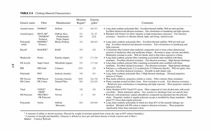
2.7
TABLE 2.4 Clothing Material Characteristics
Moisture TenacityGeneric name Fiber Manufacturer Regain* g/den† Comments
Aramid (meta) NOMEX® DuPont 5.5 4.0–5.3 • Long chain synthetic polyamide fiber. ⋅ Excellent thermal stability. Will not melt and drip. ⋅Excellent chemical and abrasion resistance. ⋅ Fair colorfastness to laundering and light exposure.
Aramid (para) KEVLAR® DuPont Akzo 4.3 21–27 • Blended with Nomex for fabric integrity in high temperature exposures. ⋅ Fair abrasionTWARON® (Netherlands) 4.0 22.6 resistance. ⋅ Sensitive to chlorine bleach, light, and strong mineral acids.Technora Teijin (Japan)
Polyamide KERMEL® Rhone-Poulenc 3.4 4.0–4.5 • Long chain synthetic polyamide fiber. ⋅ Excellent thermal stability. Will not melt andimide (France) drip. ⋅ Excellent chemical and abrasion resistance. ⋅ Fair colorfastness to laundering and
light exposure.Basofil BASOFIL® BASF 5.0 2.0 • A melamine fiber formed when methylol compounds react to form a three dimensional
structure of methylene ether and methylene bridges. ⋅ Resistant to many solvents and alkalis.Moderately resistant to acids. ⋅ Will not shrink, melt or drip when exposed to a flame.
Modacrylic Protex Kaneka (Japan) 2.5 1.7–2.6 • Long chain synthetic polymer fiber containing acrylonitrile units modified with flameretardants. ⋅ Excellent chemical resistance. ⋅ Fair abrasion resistance. ⋅ High thermal shrinkage.
FR Acrylic Super Valzer Mitsubishi (Japan) 2.5 1.7–2.6 • Long chain synthetic polymer fiber containing acrylonitrile units modified with flameretardants. ⋅ Excellent chemical resistance. ⋅ Fair abrasion resistance. ⋅ High thermal shrinkage.
PBI PBI Gold Celanese 15.0 2.8 • Polymer is a sulfonated poly (2.2-m-phenylene-5,5 bibenzim idazole). ⋅ Will not ignite, doesnot melt. ⋅ Excellent chemical resistance. ⋅ Dyeable in dark shades only.
Polyimide P84* Imitech (Austria) 3.0 4.3 • Long chain synthetic polyimide fiber. ◊ High thermal shrinkage. ⋅ Thermal propertiesinferior to Nomex.
FR Viscose PFR Rayon Lenzing (Austria) 10.0 2.6–3.0 • Man-made cellulosic, properties similar to cotton. ⋅ Fiber contains flame retardants.FR Cotton FR Cotton Natural Fiber 8.0 2.4–2.9 • Flame retardant treated in fabric form. ⋅ Poor resistance to acids. ⋅ Fair abrasion resistance.
⋅ Relatively poor colorfastness to laundering and light exposure. ⋅ Wear properties similar tountreated cotton.
Vinal VINEX® Westex 3.0 3.0 • Fabric blended of 85% Vinal/15% rayon. ⋅ Fiber composed of vinyl alcohol units with acetalFR9B® crosslinks. ⋅ Sheds aluminum splash. ⋅ Very sensitive to shrinkage from wet and dry heat.
FR Polyester TREVIRA® Trevira .4 4.5 • Polyester with proprietary organic phosphorus compound incorporated into the polymerFR Polyester chain. ⋅ Properties similar to regular polyester except as modified by flame retardants. ⋅ Melt
point 9°C lower than regular polyester.Polyamide Nylon DuPont 6.0 6.0–8.0 • Long chain synthetic polyamide in which less than 85% of the aramide linkages are
Monsanto attached. ⋅ Blended with FR cotton to improve abrasion resistance. ⋅ Wear propertiessignificantly better than untreated cotton.
* A measure of ability to absorb moisture. (Percent by weight of moisture gained from a bone dry state at 65% relative humidity.)† A measure of strength and durability. (Tenacity is defined as force per unit linear density to break a known unit of fiber.)Source: Courtesy Bulwark.
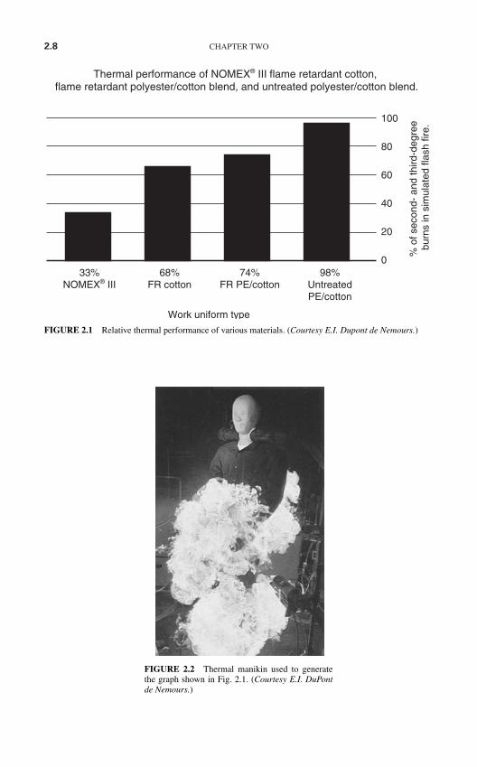
2.8 CHAPTER TWO
FIGURE 2.2 Thermal manikin used to generatethe graph shown in Fig. 2.1. (Courtesy E.I. DuPontde Nemours.)
100
80
60
40
20
0
% o
f sec
ond-
and
third
-deg
ree
burn
s in
sim
ulat
ed fl
ash
fire.
Thermal performance of NOMEX® III flame retardant cotton, flame retardant polyester/cotton blend, and untreated polyester/cotton blend.
33%NOMEX® III
68%FR cotton
74%FR PE/cotton
98%UntreatedPE/cotton
Work uniform type
FIGURE 2.1 Relative thermal performance of various materials. (Courtesy E.I. Dupont de Nemours.)
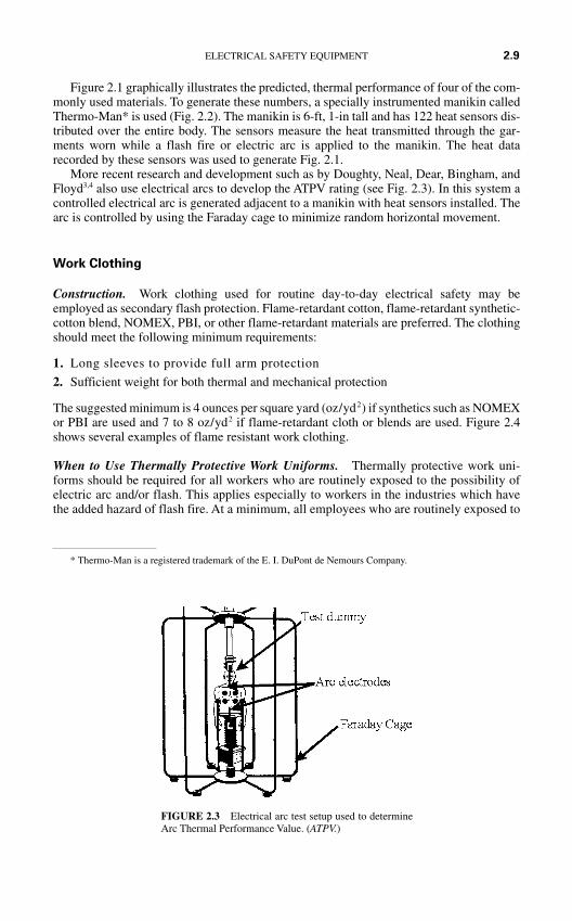
Figure 2.1 graphically illustrates the predicted, thermal performance of four of the com-monly used materials. To generate these numbers, a specially instrumented manikin calledThermo-Man* is used (Fig. 2.2). The manikin is 6-ft, 1-in tall and has 122 heat sensors dis-tributed over the entire body. The sensors measure the heat transmitted through the gar-ments worn while a flash fire or electric arc is applied to the manikin. The heat datarecorded by these sensors was used to generate Fig. 2.1.
More recent research and development such as by Doughty, Neal, Dear, Bingham, andFloyd3,4 also use electrical arcs to develop the ATPV rating (see Fig. 2.3). In this system acontrolled electrical arc is generated adjacent to a manikin with heat sensors installed. Thearc is controlled by using the Faraday cage to minimize random horizontal movement.
Work Clothing
Construction. Work clothing used for routine day-to-day electrical safety may beemployed as secondary flash protection. Flame-retardant cotton, flame-retardant synthetic-cotton blend, NOMEX, PBI, or other flame-retardant materials are preferred. The clothingshould meet the following minimum requirements:
1. Long sleeves to provide full arm protection
2. Sufficient weight for both thermal and mechanical protection
The suggested minimum is 4 ounces per square yard (oz/yd2) if synthetics such as NOMEXor PBI are used and 7 to 8 oz/yd2 if flame-retardant cloth or blends are used. Figure 2.4shows several examples of flame resistant work clothing.
When to Use Thermally Protective Work Uniforms. Thermally protective work uni-forms should be required for all workers who are routinely exposed to the possibility ofelectric arc and/or flash. This applies especially to workers in the industries which havethe added hazard of flash fire. At a minimum, all employees who are routinely exposed to
ELECTRICAL SAFETY EQUIPMENT 2.9
FIGURE 2.3 Electrical arc test setup used to determineArc Thermal Performance Value. (ATPV.)
* Thermo-Man is a registered trademark of the E. I. DuPont de Nemours Company.

2.10 CHAPTER TWO
(c) (d)
FIGURE 2.4 Thermal protective clothing. (Courtesy Bulwark Protective Apparel.)
(a) (b)
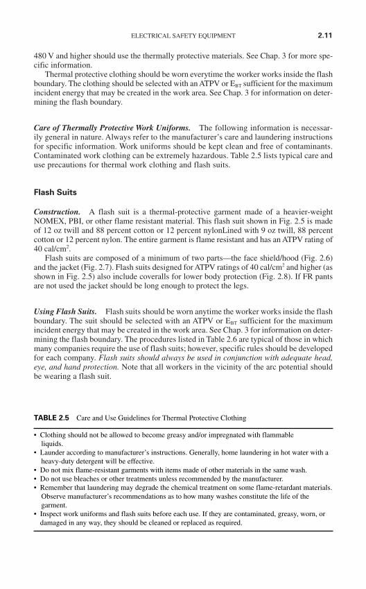
ELECTRICAL SAFETY EQUIPMENT 2.11
480 V and higher should use the thermally protective materials. See Chap. 3 for more spe-cific information.
Thermal protective clothing should be worn everytime the worker works inside the flashboundary. The clothing should be selected with an ATPV or EBT sufficient for the maximumincident energy that may be created in the work area. See Chap. 3 for information on deter-mining the flash boundary.
Care of Thermally Protective Work Uniforms. The following information is necessar-ily general in nature. Always refer to the manufacturer’s care and laundering instructionsfor specific information. Work uniforms should be kept clean and free of contaminants.Contaminated work clothing can be extremely hazardous. Table 2.5 lists typical care anduse precautions for thermal work clothing and flash suits.
Flash Suits
Construction. A flash suit is a thermal-protective garment made of a heavier-weightNOMEX, PBI, or other flame resistant material. This flash suit shown in Fig. 2.5 is madeof 12 oz twill and 88 percent cotton or 12 percent nylonLined with 9 oz twill, 88 percentcotton or 12 percent nylon. The entire garment is flame resistant and has an ATPV rating of40 cal/cm2.
Flash suits are composed of a minimum of two parts—the face shield/hood (Fig. 2.6)and the jacket (Fig. 2.7). Flash suits designed for ATPV ratings of 40 cal/cm2 and higher (asshown in Fig. 2.5) also include coveralls for lower body protection (Fig. 2.8). If FR pantsare not used the jacket should be long enough to protect the legs.
Using Flash Suits. Flash suits should be worn anytime the worker works inside the flashboundary. The suit should be selected with an ATPV or EBT sufficient for the maximumincident energy that may be created in the work area. See Chap. 3 for information on deter-mining the flash boundary. The procedures listed in Table 2.6 are typical of those in whichmany companies require the use of flash suits; however, specific rules should be developedfor each company. Flash suits should always be used in conjunction with adequate head,eye, and hand protection. Note that all workers in the vicinity of the arc potential shouldbe wearing a flash suit.
• Clothing should not be allowed to become greasy and/or impregnated with flammable liquids.
• Launder according to manufacturer’s instructions. Generally, home laundering in hot water with aheavy-duty detergent will be effective.
• Do not mix flame-resistant garments with items made of other materials in the same wash.• Do not use bleaches or other treatments unless recommended by the manufacturer.• Remember that laundering may degrade the chemical treatment on some flame-retardant materials.
Observe manufacturer’s recommendations as to how many washes constitute the life of thegarment.
• Inspect work uniforms and flash suits before each use. If they are contaminated, greasy, worn, ordamaged in any way, they should be cleaned or replaced as required.
TABLE 2.5 Care and Use Guidelines for Thermal Protective Clothing

2.12 CHAPTER TWO
Some facilities impose a current limitation on the rule as well. For example, onelarge petrochemical company requires flash suits for the procedures listed in Table 2.6,but only when the circuit breaker feeding the circuit has an ampacity of 100 A or greater.See Chap. 3 for more specific information, and methods that should be used to selectflash suits.
FIGURE 2.6 Face shield for flash suit. (CourtesyBulwark Protective Apparel.)FIGURE 2.5 Flash suit. (Courtesy Bulwark
Protective Apparel.)
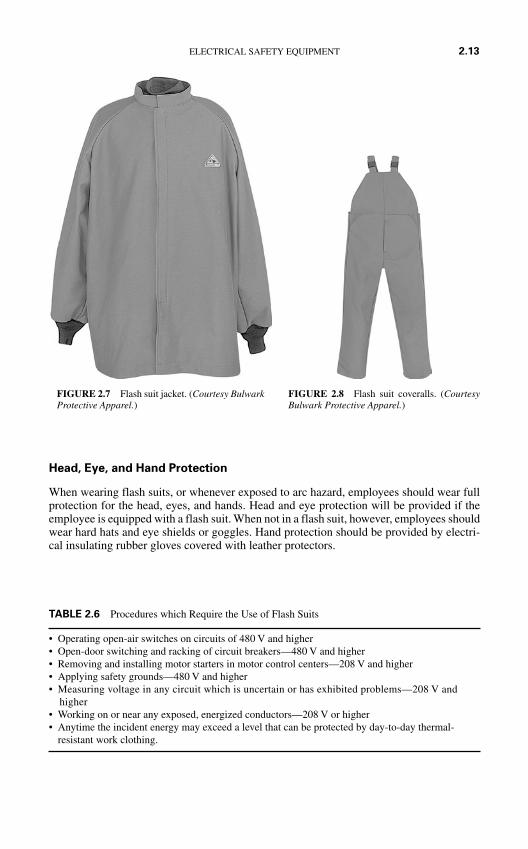
Head, Eye, and Hand Protection
When wearing flash suits, or whenever exposed to arc hazard, employees should wear fullprotection for the head, eyes, and hands. Head and eye protection will be provided if theemployee is equipped with a flash suit. When not in a flash suit, however, employees shouldwear hard hats and eye shields or goggles. Hand protection should be provided by electri-cal insulating rubber gloves covered with leather protectors.
ELECTRICAL SAFETY EQUIPMENT 2.13
FIGURE 2.8 Flash suit coveralls. (CourtesyBulwark Protective Apparel.)
• Operating open-air switches on circuits of 480 V and higher• Open-door switching and racking of circuit breakers—480 V and higher• Removing and installing motor starters in motor control centers—208 V and higher• Applying safety grounds—480 V and higher• Measuring voltage in any circuit which is uncertain or has exhibited problems—208 V and
higher• Working on or near any exposed, energized conductors—208 V or higher• Anytime the incident energy may exceed a level that can be protected by day-to-day thermal-
resistant work clothing.
TABLE 2.6 Procedures which Require the Use of Flash Suits
FIGURE 2.7 Flash suit jacket. (Courtesy BulwarkProtective Apparel.)
2.14 CHAPTER TWO
HEAD AND EYE PROTECTION
Hard Hats
Construction and Standards. In addition to wearing protection from falling objects andother blows, electrical workers should be equipped with and should wear hard hats that pro-vide electrical insulating capabilities. Such hats should comply with the latest revision ofthe American National Standards Institute (ANSI) standard Z89.1 which classifies hardhats into three basic classes.
1. Class G* hard hats are intended to reduce the force of impact of falling objects and toreduce the danger of contact with exposed low-voltage conductors. They are proof-tested by the manufacturer at 2200 V phase-to-ground.
2. Class E* hard hats are intended to reduce the force of impact of falling objects and toreduce the danger of contact with exposed high-voltage conductors. They are proof-tested by the manufacturer at 20,000 V phase-to-ground.
3. Class C hard hats are intended to reduce the force of impact of falling objects. Theyoffer no electrical protection.
Figure 2.9 shows two examples of class E (formerly class B) hard hats. Note that a hardhat must be a class G or class E hat to be used in areas where electrical shock may occur.The label for a class B (now class E) hard hat is shown in Fig. 2.10.
Use and Care. Electrically insulating class G or E hard hats should be worn by workersany time there is a possibility they will be exposed to shock, arc, blast, mechanical blows,or injuries. Table 2.7 lists typical working conditions in which workers should be wearingsuch protection.
All components of the hard hat should be inspected daily, before each use. This inspec-tion should include the shell, suspension, headband, sweatband, and any accessories. Ifdents, cracks, penetrations, or any other damage is observed, the hard hat should beremoved from service. Class G and E hard hats may be cleaned with warm water and soap.
FIGURE 2.9 Hard hats suitable for use in electri-cal installations. (Courtesy Mine Safety AppliancesCompany.)
FIGURE 2.10 Hard hat label for a class E hard hat.(Courtesy Mine Safety Appliances Company.)
* Prior to 1998 the class G hat was labeled class A and class E hats were labeled class B.
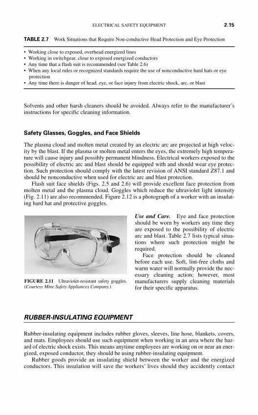
Solvents and other harsh cleaners should be avoided. Always refer to the manufacturer’sinstructions for specific cleaning information.
Safety Glasses, Goggles, and Face Shields
The plasma cloud and molten metal created by an electric arc are projected at high veloc-ity by the blast. If the plasma or molten metal enters the eyes, the extremely high tempera-ture will cause injury and possibly permanent blindness. Electrical workers exposed to thepossibility of electric arc and blast should be equipped with and should wear eye protec-tion. Such protection should comply with the latest revision of ANSI standard Z87.1 andshould be nonconductive when used for electric arc and blast protection.
Flash suit face shields (Figs. 2.5 and 2.6) will provide excellent face protection frommolten metal and the plasma cloud. Goggles which reduce the ultraviolet light intensity(Fig. 2.11) are also recommended. Figure 2.12 is a photograph of a worker with an insulat-ing hard hat and protective goggles.
Use and Care. Eye and face protectionshould be worn by workers any time theyare exposed to the possibility of electricarc and blast. Table 2.7 lists typical situa-tions where such protection might berequired.
Face protection should be cleanedbefore each use. Soft, lint-free cloths andwarm water will normally provide the nec-essary cleaning action; however, mostmanufacturers supply cleaning materialsfor their specific apparatus.
RUBBER-INSULATING EQUIPMENT
Rubber-insulating equipment includes rubber gloves, sleeves, line hose, blankets, covers,and mats. Employees should use such equipment when working in an area where the haz-ard of electric shock exists. This means anytime employees are working on or near an ener-gized, exposed conductor, they should be using rubber-insulating equipment.
Rubber goods provide an insulating shield between the worker and the energizedconductors. This insulation will save the workers’ lives should they accidently contact
ELECTRICAL SAFETY EQUIPMENT 2.15
FIGURE 2.11 Ultraviolet-resistant safety goggles.(Courtesy Mine Safety Appliances Company.)
TABLE 2.7 Work Situations that Require Non-conductive Head Protection and Eye Protection
• Working close to exposed, overhead energized lines• Working in switchgear, close to exposed energized conductors• Any time that a flash suit is recommended (see Table 2.6)• When any local rules or recognized standards require the use of nonconductive hard hats or eye
protection• Any time there is danger of head, eye, or face injury from electric shock, arc, or blast

2.16 CHAPTER TWO
the conductor. The American Society of Testing and Materials (ASTM) publishes recog-nized industry standards which cover rubber insulating goods.
Rubber Gloves
Description. A complete rubber glove assembly is composed of a minimum of two parts—the rubber glove itself and a leather protective glove. In service, the leather protector fits overthe outside of the rubber glove and protects it from physical damage and puncture. Sometimesthe glove set will include a sheer, cotton insert that serves to absorb moisture and makes wear-ing the gloves more pleasant. Figure 2.13 shows a typical set of rubber gloves with leatherprotectors. Caution: Rubber gloves should never be used without their leather protectorsexcept in certain specific situations as described later in this chapter.
Construction and Standards. The ASTM publishes four standards which affect the con-struction and use of rubber gloves.
FIGURE 2.12 Hard hat and goggles. (Courtesy Mine Safety AppliancesCompany.)
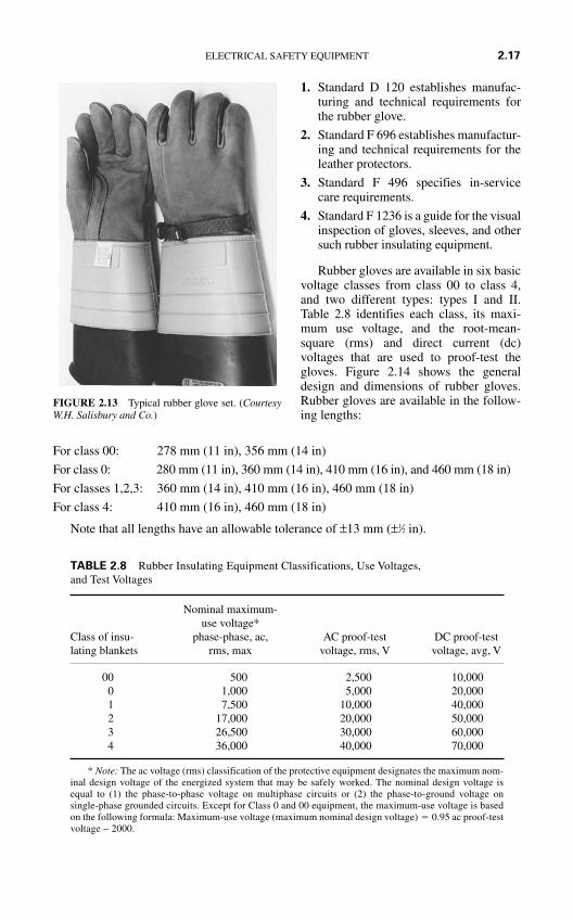
For class 00: 278 mm (11 in), 356 mm (14 in)
For class 0: 280 mm (11 in), 360 mm (14 in), 410 mm (16 in), and 460 mm (18 in)
For classes 1,2,3: 360 mm (14 in), 410 mm (16 in), 460 mm (18 in)
For class 4: 410 mm (16 in), 460 mm (18 in)
Note that all lengths have an allowable tolerance of ±13 mm (±1⁄2 in).
ELECTRICAL SAFETY EQUIPMENT 2.17
FIGURE 2.13 Typical rubber glove set. (CourtesyW.H. Salisbury and Co.)
Nominal maximum-use voltage*
Class of insu- phase-phase, ac, AC proof-test DC proof-testlating blankets rms, max voltage, rms, V voltage, avg, V
00 500 2,500 10,0000 1,000 5,000 20,0001 7,500 10,000 40,0002 17,000 20,000 50,0003 26,500 30,000 60,0004 36,000 40,000 70,000
* Note: The ac voltage (rms) classification of the protective equipment designates the maximum nom-inal design voltage of the energized system that may be safely worked. The nominal design voltage isequal to (1) the phase-to-phase voltage on multiphase circuits or (2) the phase-to-ground voltage on single-phase grounded circuits. Except for Class 0 and 00 equipment, the maximum-use voltage is basedon the following formula: Maximum-use voltage (maximum nominal design voltage) 0.95 ac proof-testvoltage − 2000.
TABLE 2.8 Rubber Insulating Equipment Classifications, Use Voltages, and Test Voltages
1. Standard D 120 establishes manufac-turing and technical requirements forthe rubber glove.
2. Standard F 696 establishes manufactur-ing and technical requirements for theleather protectors.
3. Standard F 496 specifies in-servicecare requirements.
4. Standard F 1236 is a guide for the visualinspection of gloves, sleeves, and othersuch rubber insulating equipment.
Rubber gloves are available in six basicvoltage classes from class 00 to class 4,and two different types: types I and II.Table 2.8 identifies each class, its maxi-mum use voltage, and the root-mean-square (rms) and direct current (dc)voltages that are used to proof-test thegloves. Figure 2.14 shows the generaldesign and dimensions of rubber gloves.Rubber gloves are available in the follow-ing lengths:
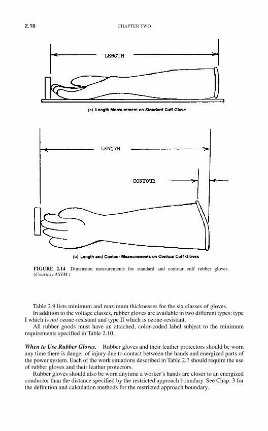
2.18 CHAPTER TWO
Table 2.9 lists minimum and maximum thicknesses for the six classes of gloves.In addition to the voltage classes, rubber gloves are available in two different types: type
I which is not ozone-resistant and type II which is ozone-resistant.All rubber goods must have an attached, color-coded label subject to the minimum
requirements specified in Table 2.10.
When to Use Rubber Gloves. Rubber gloves and their leather protectors should be wornany time there is danger of injury due to contact between the hands and energized parts ofthe power system. Each of the work situations described in Table 2.7 should require the useof rubber gloves and their leather protectors.
Rubber gloves should also be worn anytime a worker’s hands are closer to an energizedconductor than the distance specified by the restricted approach boundary. See Chap. 3 forthe definition and calculation methods for the restricted approach boundary.
FIGURE 2.14 Dimension measurements for standard and contour cuff rubber gloves.(Courtesy ASTM.)
When to Use Leather Protectors. As stated earlier in this chapter, leather protectorsshould always be used over rubber gloves to provide mechanical protection for the insulat-ing rubber. Furthermore, leather protectors should never be used for any purpose other thanprotecting rubber gloves.
Sometimes the need for additional dexterity may require that the leather protectors notbe used. The various industry standards allow such an application in only three situations.
Class 00 Up to and including 250 V, leather protectors may be omitted for Class 00gloves. Such omission is only permitted under limited-use conditions when small-partsmanipulation requires unusually good finger dexterity.
Class 0 Leather protectors may be omitted under limited-use conditions when small-parts manipulation requires unusually good finger dexterity.
Classes 1, 2, 3, 4 Under limited use conditions the leathers may be omitted. However:When the leathers are omitted for these classes, the user must employ gloves rated at leastone (1) voltage class higher than normal. For example, if working in a 4160-Volt circuitwithout leather protectors, the worker must use Class 2 gloves.
Leather protectors should never be omitted if there is even a slight possibility of physi-cal damage or puncture. Also, rubber gloves previously used without protectors shall not beused with protectors until given an inspection and electrical retest.
How to Use Rubber Gloves. Rubber gloves should be thoroughly inspected and air-testedbefore each use. They may be lightly dusted inside with talcum powder or manufacturer-supplied powder. This dusting helps to absorb perspiration and eases putting them on andremoving them. Caution: Do not use baby powder on rubber gloves. Some baby powder
ELECTRICAL SAFETY EQUIPMENT 2.19
Minimum thickness
Class ofIn crotch Other than crotch Maximum thickness
glove mm in mm in mm in
00 0.20 0.008 0.25 0.010 0.75 0.0300 0.46 0.018 0.51 0.020 1.02 0.0401 0.63 0.025 0.76 0.030 1.52 0.0602 1.02 0.040 1.27 0.050 2.29 0.0903 1.52 0.060 1.90 0.075 2.92 0.1154 2.03 0.080 2.54 0.100 3.56 0.140
Source: Courtesy ASTM.
TABLE 2.9 Rubber Glove Thickness Standard
• Color coding according to voltage class: class 00–beige. class 0–red, class 1–white,class 2–yellow, class 3–green, class 4–orange.
• Manufacturer’s name• Voltage class (00, 0, 1, 2, 3, 4)• Type• Size (gloves only)
TABLE 2.10 Labeling Requirements for Rubber Goods
2.20 CHAPTER TWO
products contain additives which can damage the glove and reduce its life and effectiveness.Cotton inserts are highly recommended for worker confort and convenience.
Rubber gloves should be applied before any activity that exposes the worker to the pos-sibility of contact with an energized conductor. As previously stated, anytime the worker’shands must be closer to an energized conductor than the restricted approach boundary, rub-ber gloves must be worn. Be certain to wear the leather protector with the glove. Alwayscheck the last test date marked on the glove and do not use it if the last test was more than6 months earlier than the present date.
Rubber Mats
Description. Rubber mats are used to cover and insulate floors for personnel protection.Rubber insulating mats should not be confused with the rubber matting used to help pre-vent slips and falls. This type of mat is sold by many commercial retail outlets and is notintended for electrical insulation purposes. Rubber insulating mats will be clearly markedand labeled as such.
Insulating rubber matting has a smooth, corrugated, or diamond design on one surfaceand may be backed with fabric. The back of the matting may be finished with cloth imprintor other slip-resistant material.
Construction and Standards. The ASTM standard D-178 specifies the design, construc-tion, and testing requirements for rubber matting.
Rubber mats are available in five basic voltage classes, from class 0 to class 4, in twodifferent types, and in three different subcategories. Table 2.8 identifies each class, its max-imum use voltage, and ac rms and dc voltages that are used to test them. Table 2.11 identi-fies each of the types and special properties for insulating mats. Table 2.12 identifies thethickness requirements for insulating mats. Table 2.13 identifies the standard widths forinsulating rubber matting.
Rubber mats must be clearly and permanently marked with the name of the manufac-turer, type, and class. ASTM D-178 must also appear on the mat. This marking is to beplaced a minimum of every 3 ft (1 m).
When to Use Rubber Mats. Employers should use rubber mats in areas where there is anongoing possibility of electric shock. Because permanently installed rubber mats are sub-ject to damage, contamination, and embedding of foreign materials, they should not berelied upon as the sole or primary source of electrical insulation.
Type I Type II
Composition Made of any elastomer or combi- Made of any elastomer or nation of elastomeric compounds, combination of elastomericproperly vulcanized compounds with one or more of
the special properties listed bysubcategory
Subcategories None A: Ozone resistantB: Flame resistantC: Oil resistant
TABLE 2.11 Types and Special Property Specifications of Insulating Rubber Matting
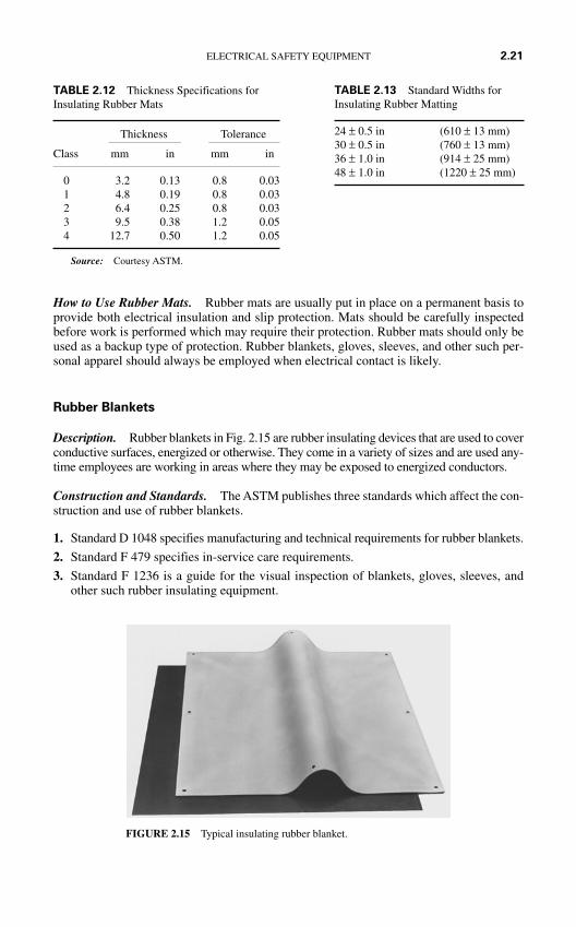
How to Use Rubber Mats. Rubber mats are usually put in place on a permanent basis toprovide both electrical insulation and slip protection. Mats should be carefully inspectedbefore work is performed which may require their protection. Rubber mats should only beused as a backup type of protection. Rubber blankets, gloves, sleeves, and other such per-sonal apparel should always be employed when electrical contact is likely.
Rubber Blankets
Description. Rubber blankets in Fig. 2.15 are rubber insulating devices that are used to coverconductive surfaces, energized or otherwise. They come in a variety of sizes and are used any-time employees are working in areas where they may be exposed to energized conductors.
Construction and Standards. The ASTM publishes three standards which affect the con-struction and use of rubber blankets.
1. Standard D 1048 specifies manufacturing and technical requirements for rubber blankets.
2. Standard F 479 specifies in-service care requirements.
3. Standard F 1236 is a guide for the visual inspection of blankets, gloves, sleeves, andother such rubber insulating equipment.
ELECTRICAL SAFETY EQUIPMENT 2.21
FIGURE 2.15 Typical insulating rubber blanket.
Thickness Tolerance
Class mm in mm in
0 3.2 0.13 0.8 0.031 4.8 0.19 0.8 0.032 6.4 0.25 0.8 0.033 9.5 0.38 1.2 0.054 12.7 0.50 1.2 0.05
Source: Courtesy ASTM.
TABLE 2.12 Thickness Specifications forInsulating Rubber Mats
24 ± 0.5 in (610 ± 13 mm)30 ± 0.5 in (760 ± 13 mm)36 ± 1.0 in (914 ± 25 mm)48 ± 1.0 in (1220 ± 25 mm)
TABLE 2.13 Standard Widths forInsulating Rubber Matting
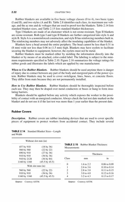
Rubber blankets are available in five basic voltage classes (0 to 4), two basic types(I and II), and two styles (A and B). Table 2.8 identifies each class, its maximum use volt-age, and the ac rms and dc voltages that are used to proof-test the blankets. Table 2.14 listsstandard blanket sizes, and Table 2.15 lists standard blanket thicknesses.
Type I blankets are made of an elastomer which is not ozone-resistant. Type II blanketsare ozone-resistant. Both type I and type II blankets are further categorized into style A andstyle B. Style A is a nonreinforced construction, and style B has reinforcing members built in.The reinforcing members may not adversely affect the insulating capabilities of the blanket.
Blankets have a bead around the entire periphery. The bead cannot be less than 0.31 in(8 mm) wide nor less than 0.06 in (1.5 mm) high. Blankets may have eyelets to facilitatesecuring the blanket to equipment; however, the eyelets must not be metal.
Rubber blankets must be marked either by molding the information directly into theblanket or by means of an attached, color-coded label. The labeling is subject to the mini-mum requirements specified in Table 2.10. Figure 2.16 summarizes the voltage ratings forrubber goods and illustrates the labels which are applied by one manufacturer.
When to Use Rubber Blankets. Rubber blankets should be used anytime there is dangerof injury due to contact between any part of the body and energized parts of the power sys-tem. Rubber blankets may be used to cover switchgear, lines, buses, or concrete floors.They differ from mats because they are not permanently installed.
How to Use Rubber Blankets. Rubber blankets should be thoroughly inspected beforeeach use. They may then be draped over metal conductors or buses or hung to form insu-lating barriers.
Blankets should be applied before any activity which exposes the worker to the possi-bility of contact with an energized conductor. Always check the last test date marked on theblanket and do not use it if the last test was more than 1 year earlier than the present date.
Rubber Covers
Description. Rubber covers are rubber insulating devices that are used to cover specificpieces of equipment to protect workers from accidental contact. They include several
2.22 CHAPTER TWO
Without slot mm (in)
457 by 910 (18 by 36)560 by 560 (22 by 22)690 by 910 (27 by 36)910 by 910 (36 by 36)910 by 2128 (36 by 84)
1160 by 1160 (45.5 by 45.5)
With slot mm (in)
560 by 560 (22 by 22)910 by 910 (36 by 36)
1160 by 1160 (45.5 by 45.5)
Source: Courtesy ASTM.
TABLE 2.14 Standard Blanket Sizes—Lengthand Width
Thickness
Class mm in
0 1.6 to 2.2 0.06 to 0.091 2.6 to 3.6 0.10 to 0.142 2.8 to 3.8 0.11 to 0.153 3.0 to 4.0 0.12 to 0.164 3.2 to 4.3 0.13 to 0.17
Source: Courtesy ASTM.
TABLE 2.15 Rubber Blanket ThicknessMeasurements
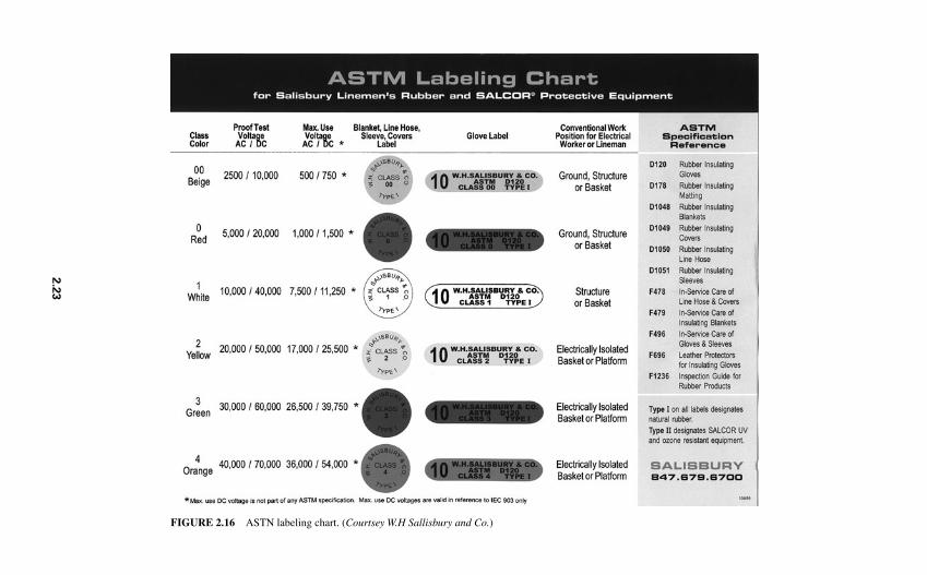
FIGURE 2.16 ASTN labeling chart. (Courtsey W.H Sallisbury and Co.)
2.2
3
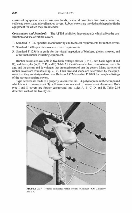
classes of equipment such as insulator hoods, dead-end protectors, line hose connectors,cable end covers, and miscellaneous covers. Rubber covers are molded and shaped to fit theequipment for which they are intended.
Construction and Standards. The ASTM publishes three standards which affect the con-struction and use of rubber covers.
1. Standard D 1049 specifies manufacturing and technical requirements for rubber covers.
2. Standard F 478 specifies in-service care requirements.
3. Standard F 1236 is a guide for the visual inspection of blankets, gloves, sleeves, andother such rubber insulating equipment.
Rubber covers are available in five basic voltage classes (0 to 4), two basic types (I andII), and five styles (A, B, C, D, and E). Table 2.8 identifies each class, its maximum use volt-age, and the ac rms and dc voltages that are used to proof-test the covers. Many varieties ofrubber covers are available (Fig. 2.17). Their size and shape are determined by the equip-ment that they are designed to cover. Refer to ASTM standard D 1049 for complete listingsof the various standard covers.
Type I covers are made of a properly vulcanized, cis-1,4-polyisoprene rubber compoundwhich is not ozone-resistant. Type II covers are made of ozone-resistant elastomers. Bothtype I and II covers are further categorized into styles A, B, C, D, and E. Table 2.16describes each of the five styles.
2.24 CHAPTER TWO
FIGURE 2.17 Typical insulating rubber covers. (Courtesy W.H. Salisbury and Co.)
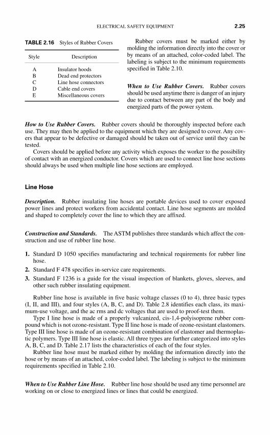
Rubber covers must be marked either bymolding the information directly into the cover orby means of an attached, color-coded label. Thelabeling is subject to the minimum requirementsspecified in Table 2.10.
When to Use Rubber Covers. Rubber coversshould be used anytime there is danger of an injurydue to contact between any part of the body andenergized parts of the power system.
How to Use Rubber Covers. Rubber covers should be thoroughly inspected before eachuse. They may then be applied to the equipment which they are designed to cover. Any cov-ers that appear to be defective or damaged should be taken out of service until they can betested.
Covers should be applied before any activity which exposes the worker to the possibilityof contact with an energized conductor. Covers which are used to connect line hose sectionsshould always be used when multiple line hose sections are employed.
Line Hose
Description. Rubber insulating line hoses are portable devices used to cover exposedpower lines and protect workers from accidental contact. Line hose segments are moldedand shaped to completely cover the line to which they are affixed.
Construction and Standards. The ASTM publishes three standards which affect the con-struction and use of rubber line hose.
1. Standard D 1050 specifies manufacturing and technical requirements for rubber linehose.
2. Standard F 478 specifies in-service care requirements.
3. Standard F 1236 is a guide for the visual inspection of blankets, gloves, sleeves, andother such rubber insulating equipment.
Rubber line hose is available in five basic voltage classes (0 to 4), three basic types(I, II, and III), and four styles (A, B, C, and D). Table 2.8 identifies each class, its maxi-mum-use voltage, and the ac rms and dc voltages that are used to proof-test them.
Type I line hose is made of a properly vulcanized, cis-1,4-polyisoprene rubber com-pound which is not ozone-resistant. Type II line hose is made of ozone-resistant elastomers.Type III line hose is made of an ozone-resistant combination of elastomer and thermoplas-tic polymers. Type III line hose is elastic. All three types are further categorized into stylesA, B, C, and D. Table 2.17 lists the characteristics of each of the four styles.
Rubber line hose must be marked either by molding the information directly into thehose or by means of an attached, color-coded label. The labeling is subject to the minimumrequirements specified in Table 2.10.
When to Use Rubber Line Hose. Rubber line hose should be used any time personnel areworking on or close to energized lines or lines that could be energized.
ELECTRICAL SAFETY EQUIPMENT 2.25
TABLE 2.16 Styles of Rubber Covers
Style Description
A Insulator hoodsB Dead end protectorsC Line hose connectorsD Cable end coversE Miscellaneous covers
2.26 CHAPTER TWO
How to Use Rubber Line Hose. Line hoses should be thoroughly inspected before eachuse. They may then be applied to the lines which they are designed to cover. Any line hosethat appears to be defective or damaged should be taken out of service until it can be tested.
Line hose should be applied before any activity which exposes the worker to the possi-bility of contact with an energized conductor. When more than one section of line hose isused, connecting line covers should be employed. The line hose should completely coverthe line.
Rubber Sleeves
Description. Rubber sleeves (Fig. 2.18) are worn by workers to protect their arms andshoulders from contact with exposed energized conductors. They fit over the arms and com-plement the rubber gloves to provide complete protection for the arms and hands. They areespecially useful when work must be performed in a cramped environment.
Style Description
A Straight style, constant cross sectionB Connect end style. Similar to straight style with connection at one endC Extended lip style with major outward extending lipsD Same as style C with a molded connector at one end
TABLE 2.17 Characteristics of the Four Styles of Line Hose
FIGURE 2.18 Insulating rubber sleeves. (Courtesy W.H. Salisbury and Co.)
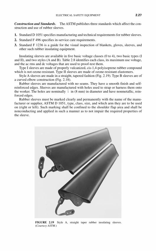
Construction and Standards. The ASTM publishes three standards which affect the con-struction and use of rubber sleeves.
1. Standard D 1051 specifies manufacturing and technical requirements for rubber sleeves.
2. Standard F 496 specifies in-service care requirements.
3. Standard F 1236 is a guide for the visual inspection of blankets, gloves, sleeves, andother such rubber insulating equipment.
Insulating sleeves are available in five basic voltage classes (0 to 4), two basic types (Iand II), and two styles (A and B). Table 2.8 identifies each class, its maximum use voltage,and the ac rms and dc voltages that are used to proof-test them.
Type I sleeves are made of properly vulcanized, cis-1,4-polyisoprene rubber compoundwhich is not ozone-resistant. Type II sleeves are made of ozone-resistant elastomers.
Style A sleeves are made in a straight, tapered fashion (Fig. 2.19). Type B sleeves are ofa curved elbow construction (Fig. 2.18).
Rubber sleeves are manufactured with no seams. They have a smooth finish and self-reinforced edges. Sleeves are manufactured with holes used to strap or harness them ontothe worker. The holes are nominally in (8 mm) in diameter and have nonmetallic, rein-forced edges.
Rubber sleeves must be marked clearly and permanently with the name of the manu-facturer or supplier, ASTM D 1051, type, class, size, and which arm they are to be usedon (right or left). Such marking shall be confined to the shoulder flap area and shall benonconducting and applied in such a manner as to not impair the required properties ofthe sleeve.
516
ELECTRICAL SAFETY EQUIPMENT 2.27
FIGURE 2.19 Style A, straight taper rubber insulating sleeves.(Courtesy ASTM.)
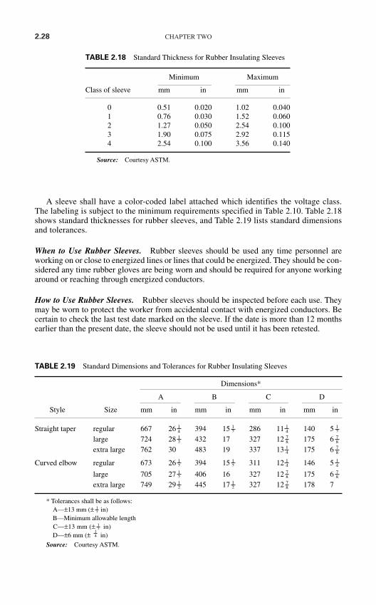
2.28 CHAPTER TWO
A sleeve shall have a color-coded label attached which identifies the voltage class.The labeling is subject to the minimum requirements specified in Table 2.10. Table 2.18shows standard thicknesses for rubber sleeves, and Table 2.19 lists standard dimensionsand tolerances.
When to Use Rubber Sleeves. Rubber sleeves should be used any time personnel areworking on or close to energized lines or lines that could be energized. They should be con-sidered any time rubber gloves are being worn and should be required for anyone workingaround or reaching through energized conductors.
How to Use Rubber Sleeves. Rubber sleeves should be inspected before each use. Theymay be worn to protect the worker from accidental contact with energized conductors. Becertain to check the last test date marked on the sleeve. If the date is more than 12 monthsearlier than the present date, the sleeve should not be used until it has been retested.
Minimum Maximum
Class of sleeve mm in mm in
0 0.51 0.020 1.02 0.0401 0.76 0.030 1.52 0.0602 1.27 0.050 2.54 0.1003 1.90 0.075 2.92 0.1154 2.54 0.100 3.56 0.140
Source: Courtesy ASTM.
TABLE 2.18 Standard Thickness for Rubber Insulating Sleeves
Dimensions*
A B C D
Style Size mm in mm in mm in mm in
Straight taper regular 667 26 394 15 286 11 140 5large 724 28 432 17 327 12 175 6extra large 762 30 483 19 337 13 175 6
Curved elbow regular 673 26 394 15 311 12 146 5
large 705 27 406 16 327 12 175 6extra large 749 29 445 17 327 12 178 7
* Tolerances shall be as follows:A—±13 mm (± in)B—Minimum allowable lengthC—±13 mm (± in)D—±6 mm (± in)
Source: Courtesy ASTM.
14
12
12
78
12
12
78
78
12
14
14
12
12
78
14
78
78
12
12
14
12
14
TABLE 2.19 Standard Dimensions and Tolerances for Rubber Insulating Sleeves
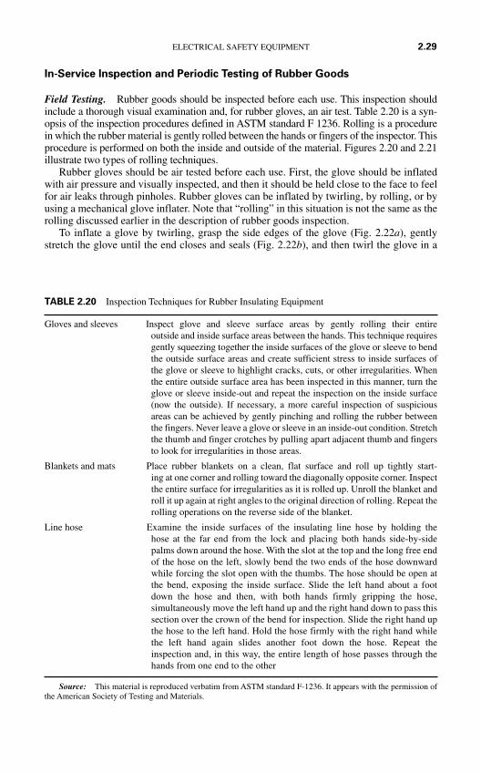
In-Service Inspection and Periodic Testing of Rubber Goods
Field Testing. Rubber goods should be inspected before each use. This inspection shouldinclude a thorough visual examination and, for rubber gloves, an air test. Table 2.20 is a syn-opsis of the inspection procedures defined in ASTM standard F 1236. Rolling is a procedurein which the rubber material is gently rolled between the hands or fingers of the inspector. Thisprocedure is performed on both the inside and outside of the material. Figures 2.20 and 2.21illustrate two types of rolling techniques.
Rubber gloves should be air tested before each use. First, the glove should be inflatedwith air pressure and visually inspected, and then it should be held close to the face to feelfor air leaks through pinholes. Rubber gloves can be inflated by twirling, by rolling, or byusing a mechanical glove inflater. Note that “rolling” in this situation is not the same as therolling discussed earlier in the description of rubber goods inspection.
To inflate a glove by twirling, grasp the side edges of the glove (Fig. 2.22a), gentlystretch the glove until the end closes and seals (Fig. 2.22b), and then twirl the glove in a
ELECTRICAL SAFETY EQUIPMENT 2.29
Gloves and sleeves Inspect glove and sleeve surface areas by gently rolling their entireoutside and inside surface areas between the hands. This technique requiresgently squeezing together the inside surfaces of the glove or sleeve to bendthe outside surface areas and create sufficient stress to inside surfaces ofthe glove or sleeve to highlight cracks, cuts, or other irregularities. Whenthe entire outside surface area has been inspected in this manner, turn theglove or sleeve inside-out and repeat the inspection on the inside surface(now the outside). If necessary, a more careful inspection of suspiciousareas can be achieved by gently pinching and rolling the rubber betweenthe fingers. Never leave a glove or sleeve in an inside-out condition. Stretchthe thumb and finger crotches by pulling apart adjacent thumb and fingersto look for irregularities in those areas.
Blankets and mats Place rubber blankets on a clean, flat surface and roll up tightly start-ing at one corner and rolling toward the diagonally opposite corner. Inspectthe entire surface for irregularities as it is rolled up. Unroll the blanket androll it up again at right angles to the original direction of rolling. Repeat therolling operations on the reverse side of the blanket.
Line hose Examine the inside surfaces of the insulating line hose by holding thehose at the far end from the lock and placing both hands side-by-sidepalms down around the hose. With the slot at the top and the long free endof the hose on the left, slowly bend the two ends of the hose downwardwhile forcing the slot open with the thumbs. The hose should be open atthe bend, exposing the inside surface. Slide the left hand about a footdown the hose and then, with both hands firmly gripping the hose,simultaneously move the left hand up and the right hand down to pass thissection over the crown of the bend for inspection. Slide the right hand upthe hose to the left hand. Hold the hose firmly with the right hand whilethe left hand again slides another foot down the hose. Repeat theinspection and, in this way, the entire length of hose passes through thehands from one end to the other
Source: This material is reproduced verbatim from ASTM standard F-1236. It appears with the permission ofthe American Society of Testing and Materials.
TABLE 2.20 Inspection Techniques for Rubber Insulating Equipment
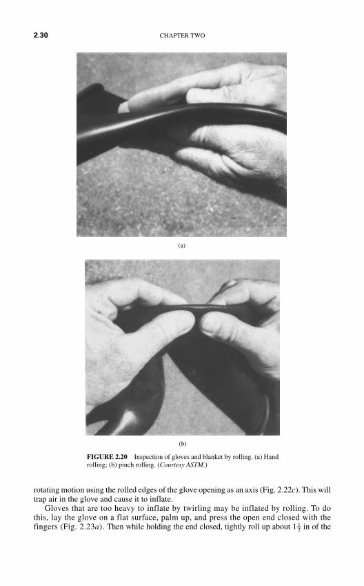
rotating motion using the rolled edges of the glove opening as an axis (Fig. 2.22c). This willtrap air in the glove and cause it to inflate.
Gloves that are too heavy to inflate by twirling may be inflated by rolling. To dothis, lay the glove on a flat surface, palm up, and press the open end closed with thefingers (Fig. 2.23a). Then while holding the end closed, tightly roll up about 1 in of the1
2
2.30 CHAPTER TWO
(b)
FIGURE 2.20 Inspection of gloves and blanket by rolling. (a) Handrolling; (b) pinch rolling. (Courtesy ASTM.)
(a)
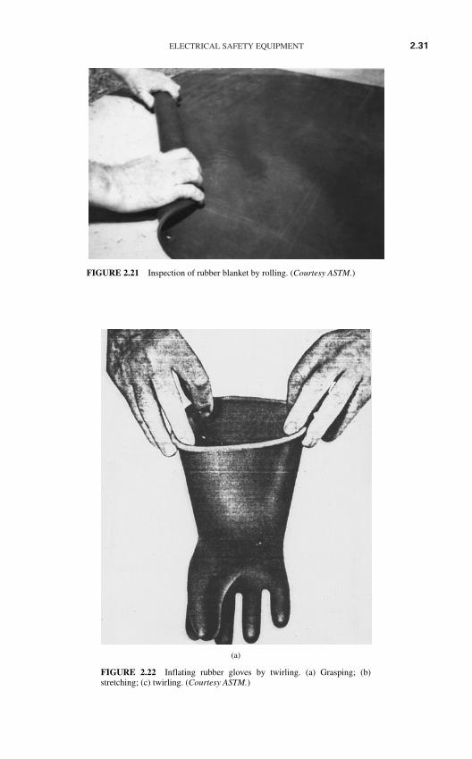
ELECTRICAL SAFETY EQUIPMENT 2.31
FIGURE 2.21 Inspection of rubber blanket by rolling. (Courtesy ASTM.)
(a)
FIGURE 2.22 Inflating rubber gloves by twirling. (a) Grasping; (b)stretching; (c) twirling. (Courtesy ASTM.)
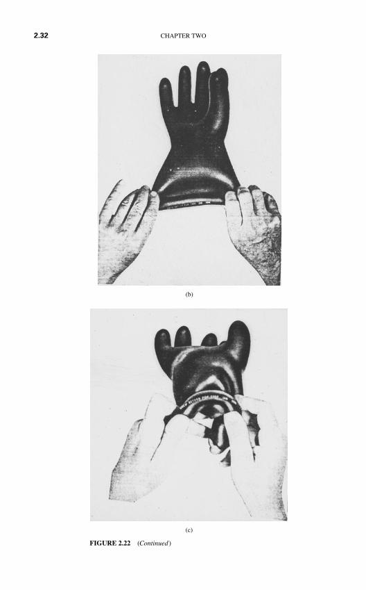
(c)
FIGURE 2.22 (Continued)
(b)
2.32 CHAPTER TWO
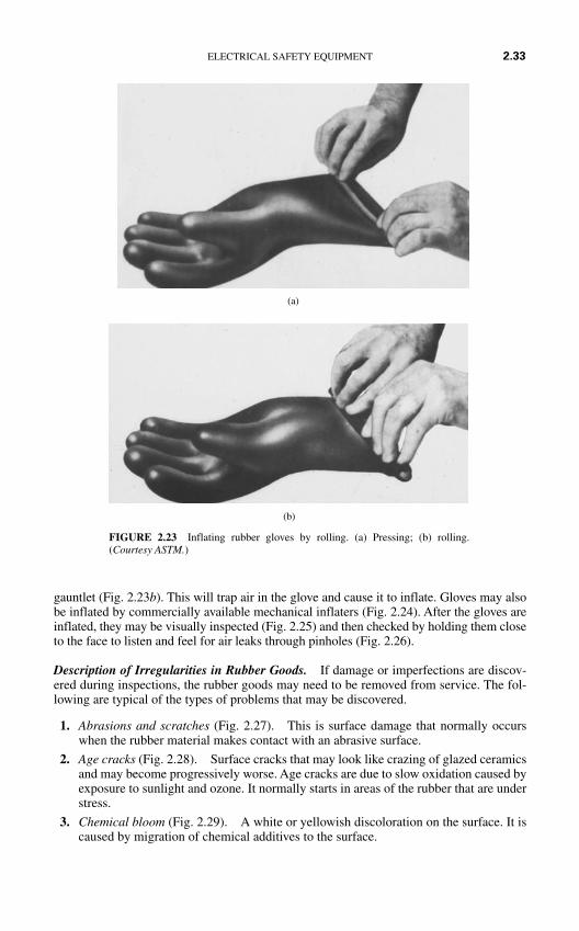
gauntlet (Fig. 2.23b). This will trap air in the glove and cause it to inflate. Gloves may alsobe inflated by commercially available mechanical inflaters (Fig. 2.24). After the gloves areinflated, they may be visually inspected (Fig. 2.25) and then checked by holding them closeto the face to listen and feel for air leaks through pinholes (Fig. 2.26).
Description of Irregularities in Rubber Goods. If damage or imperfections are discov-ered during inspections, the rubber goods may need to be removed from service. The fol-lowing are typical of the types of problems that may be discovered.
1. Abrasions and scratches (Fig. 2.27). This is surface damage that normally occurswhen the rubber material makes contact with an abrasive surface.
2. Age cracks (Fig. 2.28). Surface cracks that may look like crazing of glazed ceramicsand may become progressively worse. Age cracks are due to slow oxidation caused byexposure to sunlight and ozone. It normally starts in areas of the rubber that are understress.
3. Chemical bloom (Fig. 2.29). A white or yellowish discoloration on the surface. It iscaused by migration of chemical additives to the surface.
ELECTRICAL SAFETY EQUIPMENT 2.33
(b)
FIGURE 2.23 Inflating rubber gloves by rolling. (a) Pressing; (b) rolling.(Courtesy ASTM.)
(a)
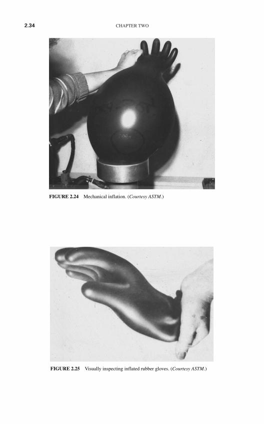
2.34 CHAPTER TWO
FIGURE 2.24 Mechanical inflation. (Courtesy ASTM.)
FIGURE 2.25 Visually inspecting inflated rubber gloves. (Courtesy ASTM.)
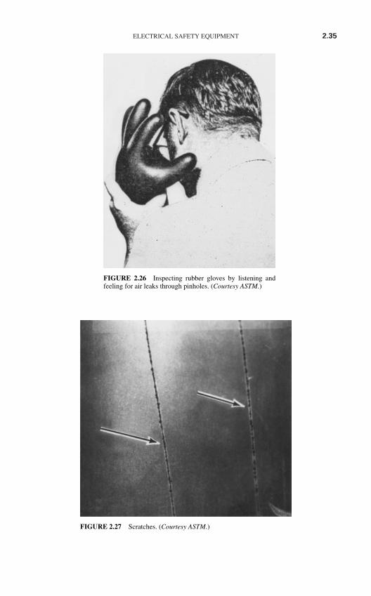
ELECTRICAL SAFETY EQUIPMENT 2.35
FIGURE 2.26 Inspecting rubber gloves by listening andfeeling for air leaks through pinholes. (Courtesy ASTM.)
FIGURE 2.27 Scratches. (Courtesy ASTM.)
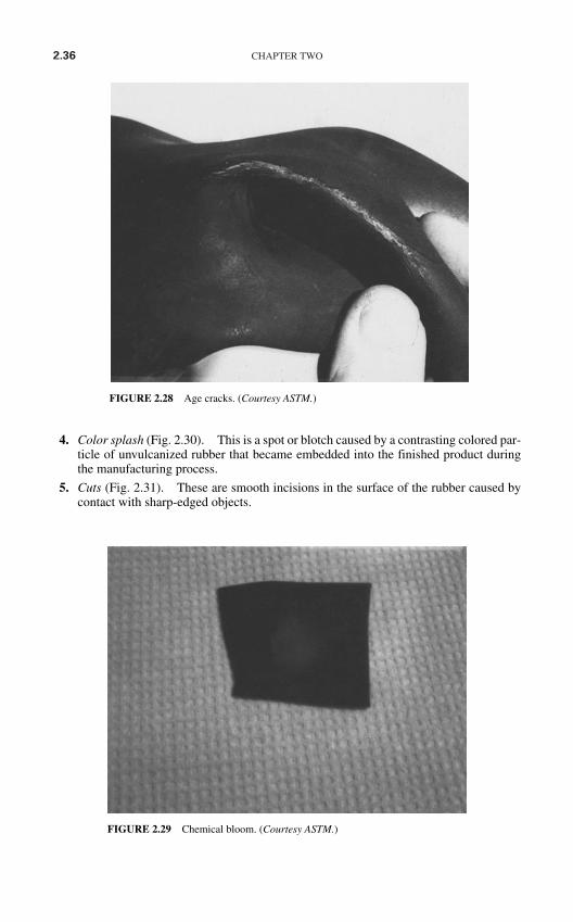
2.36 CHAPTER TWO
4. Color splash (Fig. 2.30). This is a spot or blotch caused by a contrasting colored par-ticle of unvulcanized rubber that became embedded into the finished product duringthe manufacturing process.
5. Cuts (Fig. 2.31). These are smooth incisions in the surface of the rubber caused bycontact with sharp-edged objects.
FIGURE 2.28 Age cracks. (Courtesy ASTM.)
FIGURE 2.29 Chemical bloom. (Courtesy ASTM.)
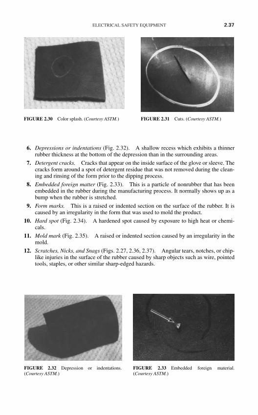
ELECTRICAL SAFETY EQUIPMENT 2.37
FIGURE 2.30 Color splash. (Courtesy ASTM.) FIGURE 2.31 Cuts. (Courtesy ASTM.)
6. Depressions or indentations (Fig. 2.32). A shallow recess which exhibits a thinnerrubber thickness at the bottom of the depression than in the surrounding areas.
7. Detergent cracks. Cracks that appear on the inside surface of the glove or sleeve. Thecracks form around a spot of detergent residue that was not removed during the clean-ing and rinsing of the form prior to the dipping process.
8. Embedded foreign matter (Fig. 2.33). This is a particle of nonrubber that has beenembedded in the rubber during the manufacturing process. It normally shows up as abump when the rubber is stretched.
9. Form marks. This is a raised or indented section on the surface of the rubber. It iscaused by an irregularity in the form that was used to mold the product.
10. Hard spot (Fig. 2.34). A hardened spot caused by exposure to high heat or chemi-cals.
11. Mold mark (Fig. 2.35). A raised or indented section caused by an irregularity in themold.
12. Scratches, Nicks, and Snags (Figs. 2.27, 2.36, 2.37). Angular tears, notches, or chip-like injuries in the surface of the rubber caused by sharp objects such as wire, pointedtools, staples, or other similar sharp-edged hazards.
FIGURE 2.32 Depression or indentations.(Courtesy ASTM.)
FIGURE 2.33 Embedded foreign material.(Courtesy ASTM.)

2.38 CHAPTER TWO
(b)
FIGURE 2.34 Hard spot. (Courtesy ASTM.)
(a)
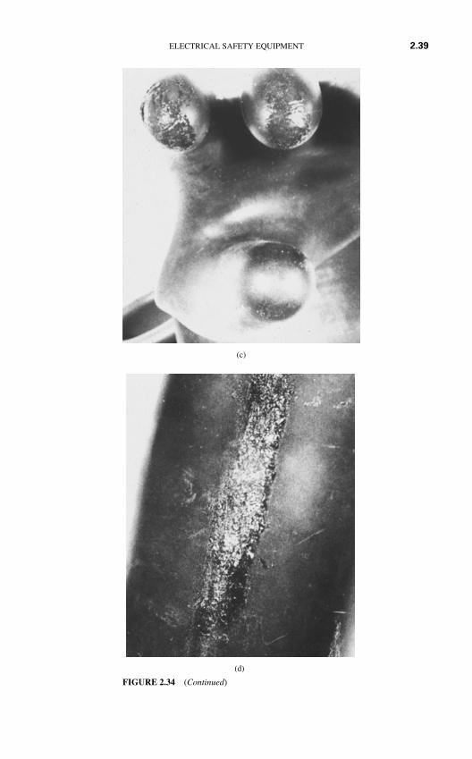
ELECTRICAL SAFETY EQUIPMENT 2.39
(c)
(d)
FIGURE 2.34 (Continued)
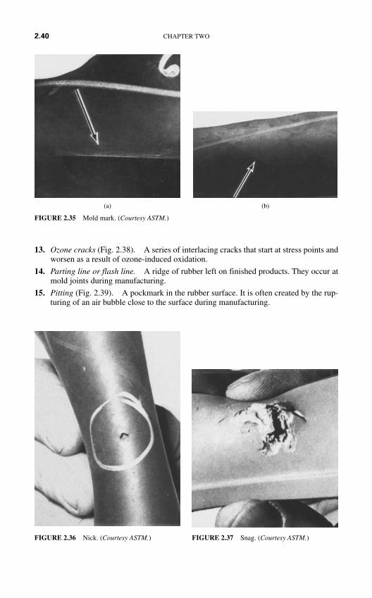
13. Ozone cracks (Fig. 2.38). A series of interlacing cracks that start at stress points andworsen as a result of ozone-induced oxidation.
14. Parting line or flash line. A ridge of rubber left on finished products. They occur atmold joints during manufacturing.
15. Pitting (Fig. 2.39). A pockmark in the rubber surface. It is often created by the rup-turing of an air bubble close to the surface during manufacturing.
2.40 CHAPTER TWO
(b)(a)
FIGURE 2.36 Nick. (Courtesy ASTM.) FIGURE 2.37 Snag. (Courtesy ASTM.)
FIGURE 2.35 Mold mark. (Courtesy ASTM.)
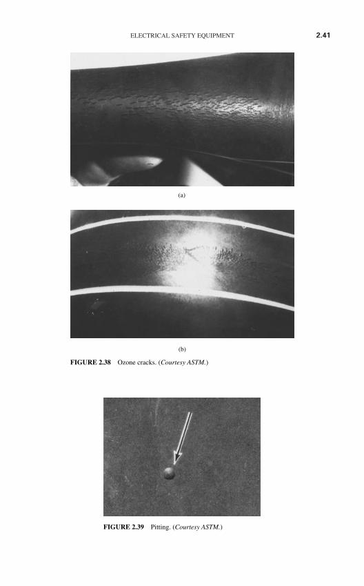
ELECTRICAL SAFETY EQUIPMENT 2.41
(b)
FIGURE 2.38 Ozone cracks. (Courtesy ASTM.)
(a)
FIGURE 2.39 Pitting. (Courtesy ASTM.)
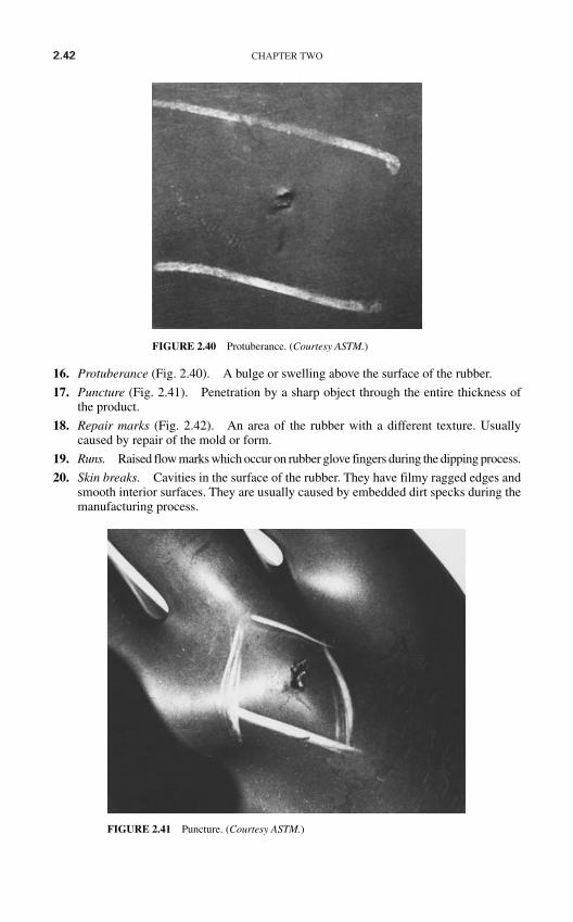
2.42 CHAPTER TWO
16. Protuberance (Fig. 2.40). A bulge or swelling above the surface of the rubber.
17. Puncture (Fig. 2.41). Penetration by a sharp object through the entire thickness ofthe product.
18. Repair marks (Fig. 2.42). An area of the rubber with a different texture. Usuallycaused by repair of the mold or form.
19. Runs. Raised flow marks which occur on rubber glove fingers during the dipping process.
20. Skin breaks. Cavities in the surface of the rubber. They have filmy ragged edges andsmooth interior surfaces. They are usually caused by embedded dirt specks during themanufacturing process.
FIGURE 2.40 Protuberance. (Courtesy ASTM.)
FIGURE 2.41 Puncture. (Courtesy ASTM.)
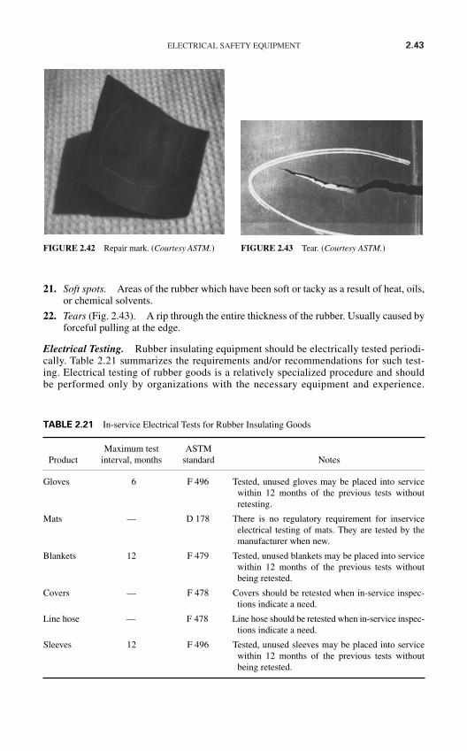
ELECTRICAL SAFETY EQUIPMENT 2.43
FIGURE 2.42 Repair mark. (Courtesy ASTM.) FIGURE 2.43 Tear. (Courtesy ASTM.)
21. Soft spots. Areas of the rubber which have been soft or tacky as a result of heat, oils,or chemical solvents.
22. Tears (Fig. 2.43). A rip through the entire thickness of the rubber. Usually caused byforceful pulling at the edge.
Electrical Testing. Rubber insulating equipment should be electrically tested periodi-cally. Table 2.21 summarizes the requirements and/or recommendations for such test-ing. Electrical testing of rubber goods is a relatively specialized procedure and shouldbe performed only by organizations with the necessary equipment and experience.
Maximum test ASTMProduct interval, months standard Notes
Gloves 6 F 496 Tested, unused gloves may be placed into servicewithin 12 months of the previous tests withoutretesting.
Mats — D 178 There is no regulatory requirement for inserviceelectrical testing of mats. They are tested by themanufacturer when new.
Blankets 12 F 479 Tested, unused blankets may be placed into servicewithin 12 months of the previous tests withoutbeing retested.
Covers — F 478 Covers should be retested when in-service inspec-tions indicate a need.
Line hose — F 478 Line hose should be retested when in-service inspec-tions indicate a need.
Sleeves 12 F 496 Tested, unused sleeves may be placed into servicewithin 12 months of the previous tests withoutbeing retested.
TABLE 2.21 In-service Electrical Tests for Rubber Insulating Goods
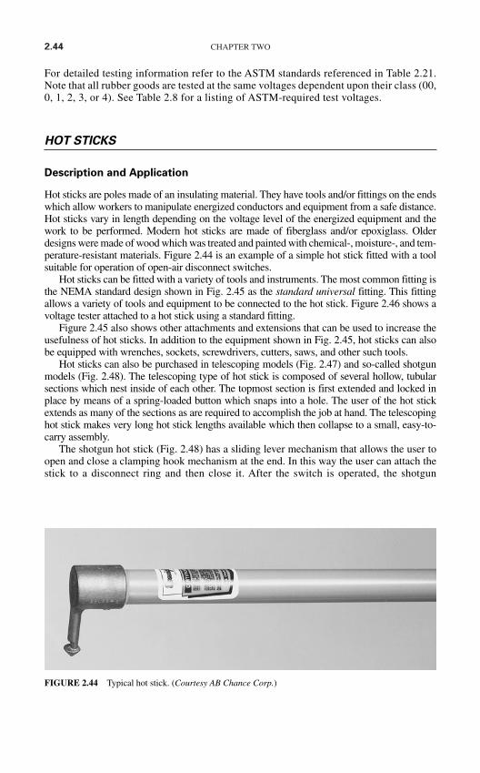
2.44 CHAPTER TWO
For detailed testing information refer to the ASTM standards referenced in Table 2.21.Note that all rubber goods are tested at the same voltages dependent upon their class (00,0, 1, 2, 3, or 4). See Table 2.8 for a listing of ASTM-required test voltages.
HOT STICKS
Description and Application
Hot sticks are poles made of an insulating material. They have tools and/or fittings on the endswhich allow workers to manipulate energized conductors and equipment from a safe distance.Hot sticks vary in length depending on the voltage level of the energized equipment and thework to be performed. Modern hot sticks are made of fiberglass and/or epoxiglass. Olderdesigns were made of wood which was treated and painted with chemical-, moisture-, and tem-perature-resistant materials. Figure 2.44 is an example of a simple hot stick fitted with a toolsuitable for operation of open-air disconnect switches.
Hot sticks can be fitted with a variety of tools and instruments. The most common fitting isthe NEMA standard design shown in Fig. 2.45 as the standard universal fitting. This fittingallows a variety of tools and equipment to be connected to the hot stick. Figure 2.46 shows avoltage tester attached to a hot stick using a standard fitting.
Figure 2.45 also shows other attachments and extensions that can be used to increase theusefulness of hot sticks. In addition to the equipment shown in Fig. 2.45, hot sticks can alsobe equipped with wrenches, sockets, screwdrivers, cutters, saws, and other such tools.
Hot sticks can also be purchased in telescoping models (Fig. 2.47) and so-called shotgunmodels (Fig. 2.48). The telescoping type of hot stick is composed of several hollow, tubularsections which nest inside of each other. The topmost section is first extended and locked inplace by means of a spring-loaded button which snaps into a hole. The user of the hot stickextends as many of the sections as are required to accomplish the job at hand. The telescopinghot stick makes very long hot stick lengths available which then collapse to a small, easy-to-carry assembly.
The shotgun hot stick (Fig. 2.48) has a sliding lever mechanism that allows the user toopen and close a clamping hook mechanism at the end. In this way the user can attach thestick to a disconnect ring and then close it. After the switch is operated, the shotgun
FIGURE 2.44 Typical hot stick. (Courtesy AB Chance Corp.)
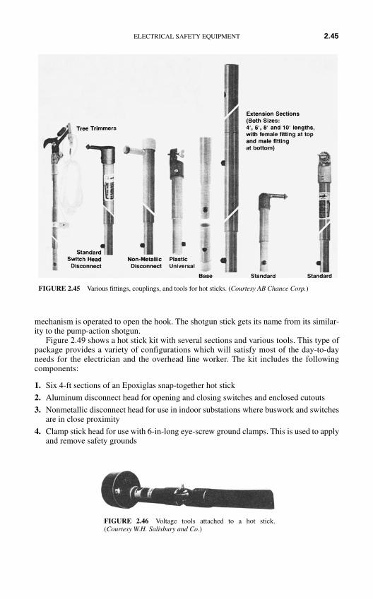
mechanism is operated to open the hook. The shotgun stick gets its name from its similar-ity to the pump-action shotgun.
Figure 2.49 shows a hot stick kit with several sections and various tools. This type ofpackage provides a variety of configurations which will satisfy most of the day-to-dayneeds for the electrician and the overhead line worker. The kit includes the followingcomponents:
1. Six 4-ft sections of an Epoxiglas snap-together hot stick
2. Aluminum disconnect head for opening and closing switches and enclosed cutouts
3. Nonmetallic disconnect head for use in indoor substations where buswork and switchesare in close proximity
4. Clamp stick head for use with 6-in-long eye-screw ground clamps. This is used to applyand remove safety grounds
ELECTRICAL SAFETY EQUIPMENT 2.45
FIGURE 2.45 Various fittings, couplings, and tools for hot sticks. (Courtesy AB Chance Corp.)
FIGURE 2.46 Voltage tools attached to a hot stick.(Courtesy W.H. Salisbury and Co.)

2.46 CHAPTER TWO
5. Tree trimmer attachment with 1 ft ofadditional stick and pull rope used toclose jaws of the trimmer
6. Pruning saw
7. Pistol-grip saw handle for use when treelimbs can be reached and insulation isnot required
8. Heavy-duty vinyl-impregnated storagecase
Electricians involved primarily in indoor work might wish to substitute other tools for thetree trimming and pruning attachments.
12
FIGURE 2.47 Telescoping hot stick—shown col-lapsed. (Courtesy AB Chance Corp.)
FIGURE 2.48 Shotgun-type hot stick. (CourtesyAB Chance Corp.)
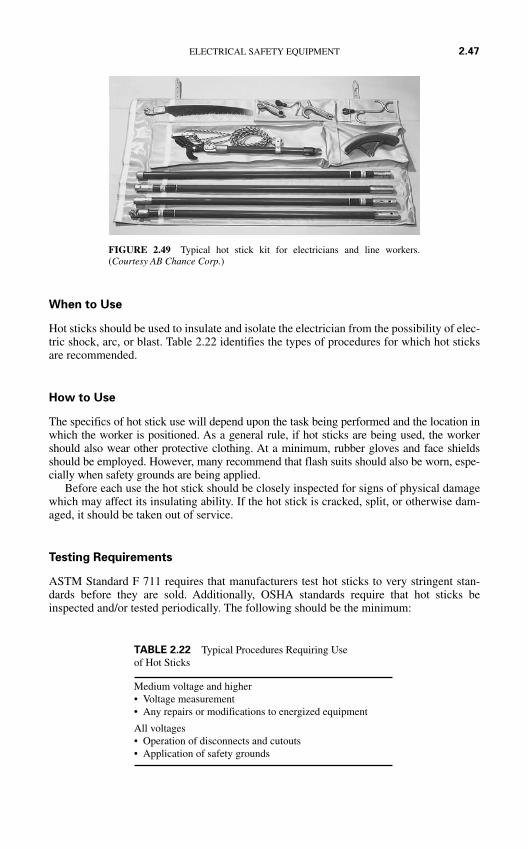
When to Use
Hot sticks should be used to insulate and isolate the electrician from the possibility of elec-tric shock, arc, or blast. Table 2.22 identifies the types of procedures for which hot sticksare recommended.
How to Use
The specifics of hot stick use will depend upon the task being performed and the location inwhich the worker is positioned. As a general rule, if hot sticks are being used, the workershould also wear other protective clothing. At a minimum, rubber gloves and face shieldsshould be employed. However, many recommend that flash suits should also be worn, espe-cially when safety grounds are being applied.
Before each use the hot stick should be closely inspected for signs of physical damagewhich may affect its insulating ability. If the hot stick is cracked, split, or otherwise dam-aged, it should be taken out of service.
Testing Requirements
ASTM Standard F 711 requires that manufacturers test hot sticks to very stringent stan-dards before they are sold. Additionally, OSHA standards require that hot sticks beinspected and/or tested periodically. The following should be the minimum:
ELECTRICAL SAFETY EQUIPMENT 2.47
FIGURE 2.49 Typical hot stick kit for electricians and line workers.(Courtesy AB Chance Corp.)
Medium voltage and higher• Voltage measurement• Any repairs or modifications to energized equipment
All voltages• Operation of disconnects and cutouts• Application of safety grounds
TABLE 2.22 Typical Procedures Requiring Use of Hot Sticks

2.48 CHAPTER TWO
1. Hot sticks should be closely inspected for damage or defectsa. Prior to each useb. At least every two years
2. If any damage or defects are noted the hot stick should be repaired or replaced
3. Hot sticks should be electrically tested according to ASTM Standard F 711a. Anytime an inspection reveals damage or a defectb. Every two years
INSULATED TOOLS
Description and Application
Insulated tools, such as those shown in Fig. 2.50, are standard hand tools with a completecovering of electrical insulation. Every part of the tool is fully insulated. Only the mini-mum amount of metallic work surface is left exposed. Such tools are used to prevent shockor arc in the event that the worker contacts the energized conductor.
ASTM Standard 1505 defines the requirements for the manufacture and testingof insulated hand tools. Such tools are to be used in circuits of 1000 V ac and 1500 Vdc. Such tools are covered with two layers of material. The inner layer provides the
FIGURE 2.50 Insulated tool set. (Courtesy CIP Insulated Products.)
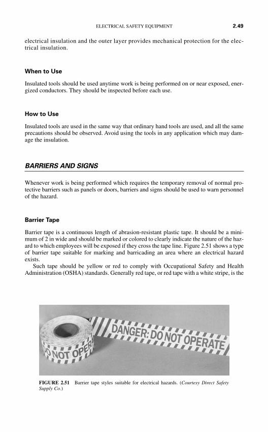
electrical insulation and the outer layer provides mechanical protection for the elec-trical insulation.
When to Use
Insulated tools should be used anytime work is being performed on or near exposed, ener-gized conductors. They should be inspected before each use.
How to Use
Insulated tools are used in the same way that ordinary hand tools are used, and all the sameprecautions should be observed. Avoid using the tools in any application which may dam-age the insulation.
BARRIERS AND SIGNS
Whenever work is being performed which requires the temporary removal of normal pro-tective barriers such as panels or doors, barriers and signs should be used to warn personnelof the hazard.
Barrier Tape
Barrier tape is a continuous length of abrasion-resistant plastic tape. It should be a mini-mum of 2 in wide and should be marked or colored to clearly indicate the nature of the haz-ard to which employees will be exposed if they cross the tape line. Figure 2.51 shows a typeof barrier tape suitable for marking and barricading an area where an electrical hazardexists.
Such tape should be yellow or red to comply with Occupational Safety and HealthAdministration (OSHA) standards. Generally red tape, or red tape with a white stripe, is the
ELECTRICAL SAFETY EQUIPMENT 2.49
FIGURE 2.51 Barrier tape styles suitable for electrical hazards. (Courtesy Direct SafetySupply Co.)
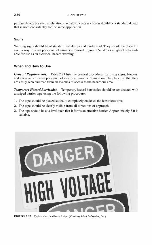
2.50 CHAPTER TWO
preferred color for such applications. Whatever color is chosen should be a standard designthat is used consistently for the same application.
Signs
Warning signs should be of standardized design and easily read. They should be placed insuch a way to warn personnel of imminent hazard. Figure 2.52 shows a type of sign suit-able for use as an electrical hazard warning.
When and How to Use
General Requirements. Table 2.23 lists the general procedures for using signs, barriers,and attendants to warn personnel of electrical hazards. Signs should be placed so that theyare easily seen and read from all avenues of access to the hazardous area.
Temporary Hazard Barricades. Temporary hazard barricades should be constructed witha striped barrier tape using the following procedure:
1. The tape should be placed so that it completely encloses the hazardous area.
2. The tape should be clearly visible from all directions of approach.
3. The tape should be at a level such that it forms an effective barrier. Approximately 3 ft issuitable.
FIGURE 2.52 Typical electrical hazard sign. (Courtesy Ideal Industries, Inc.)
4. Allow an area of sufficient size to give adequate clearance between the hazard and anypersonnel outside the hazardous area.
5. If test equipment is being used on equipment inside the hazardous area, the tape shouldbe arranged so that the equipment can be operated outside the area.
6. Do not use the same style and color of tape for any purpose other than marking tempo-rary hazards.
7. Such a barricaded area should be considered to be the same as a metal enclosure; thatis, access is not possible.
8. After the hazard has been eliminated, remove the tape.
SAFETY TAGS, LOCKS, AND LOCKING DEVICES
Safety tags, locks, and locking devices are used to secure and mark equipment that has beentaken out of service. They are applied in such a way that the equipment cannot be reener-gized without first removing the tags and/or locks. For more information about lockout andtagout procedures refer to Chap. 3.
Safety Tags
Safety tags are applied to equipment to indicate that the equipment is not available for ser-vice. They are tags constructed of a durable, environment-proof material. They should beof standardized construction and include a warning that says Do Not Start, Do Not Open,Do Not Close, Do Not Operate, or other such warning. The tag must also indicate whoplaced it on the equipment and the nature of the problem with the equipment. Figure 2.53shows tags which are suitable for such an application.
Some manufacturers supply tags with individual employee photographs on them. Thistype of tag helps to further identify who placed the tag and to personalize the installation.
Tags are to be applied using strong, self-locking fasteners. Nylon cable wraps are suitablefor such an application. The fastener must have a breaking strength of not less than 50 lb.
ELECTRICAL SAFETY EQUIPMENT 2.51
Type of warning When to use
Signs Signs should be placed to warn employees about electrical hazardswhich may harm them
Barricades Barricades should be used to prevent and limit employee access towork areas where they may be exposed to electrical hazards. Such barriersshould be made of nonconductive material such as plastic barrier tape
Attendants If signs and/or barricades cannot provide a level of safety sufficient toprotect employees, attendants shall be placed to guard hazardous areas.Attendants shall be familiar with the nature and extent of the hazard so as toadequately warn other employees
TABLE 2.23 Summary of the Use of Warning Methods
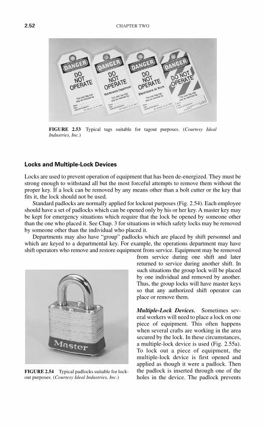
2.52 CHAPTER TWO
Locks and Multiple-Lock Devices
Locks are used to prevent operation of equipment that has been de-energized. They must bestrong enough to withstand all but the most forceful attempts to remove them without theproper key. If a lock can be removed by any means other than a bolt cutter or the key thatfits it, the lock should not be used.
Standard padlocks are normally applied for lockout purposes (Fig. 2.54). Each employeeshould have a set of padlocks which can be opened only by his or her key. A master key maybe kept for emergency situations which require that the lock be opened by someone otherthan the one who placed it. See Chap. 3 for situations in which safety locks may be removedby someone other than the individual who placed it.
Departments may also have “group” padlocks which are placed by shift personnel andwhich are keyed to a departmental key. For example, the operations department may haveshift operators who remove and restore equipment from service. Equipment may be removed
from service during one shift and laterreturned to service during another shift. Insuch situations the group lock will be placedby one individual and removed by another.Thus, the group locks will have master keysso that any authorized shift operator canplace or remove them.
Multiple-Lock Devices. Sometimes sev-eral workers will need to place a lock on onepiece of equipment. This often happenswhen several crafts are working in the areasecured by the lock. In these circumstances,a multiple-lock device is used (Fig. 2.55a).To lock out a piece of equipment, themultiple-lock device is first opened andapplied as though it were a padlock. Thenthe padlock is inserted through one of theholes in the device. The padlock prevents
FIGURE 2.53 Typical tags suitable for tagout purposes. (Courtesy IdealIndustries, Inc.)
FIGURE 2.54 Typical padlocks suitable for lock-out purposes. (Courtesy Ideal Industries, Inc.)
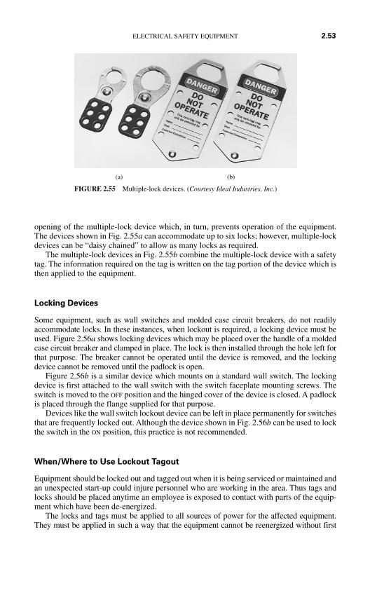
opening of the multiple-lock device which, in turn, prevents operation of the equipment.The devices shown in Fig. 2.55a can accommodate up to six locks; however, multiple-lockdevices can be “daisy chained” to allow as many locks as required.
The multiple-lock devices in Fig. 2.55b combine the multiple-lock device with a safetytag. The information required on the tag is written on the tag portion of the device which isthen applied to the equipment.
Locking Devices
Some equipment, such as wall switches and molded case circuit breakers, do not readilyaccommodate locks. In these instances, when lockout is required, a locking device must beused. Figure 2.56a shows locking devices which may be placed over the handle of a moldedcase circuit breaker and clamped in place. The lock is then installed through the hole left forthat purpose. The breaker cannot be operated until the device is removed, and the lockingdevice cannot be removed until the padlock is open.
Figure 2.56b is a similar device which mounts on a standard wall switch. The lockingdevice is first attached to the wall switch with the switch faceplate mounting screws. Theswitch is moved to the OFF position and the hinged cover of the device is closed. A padlockis placed through the flange supplied for that purpose.
Devices like the wall switch lockout device can be left in place permanently for switchesthat are frequently locked out. Although the device shown in Fig. 2.56b can be used to lockthe switch in the ON position, this practice is not recommended.
When/Where to Use Lockout Tagout
Equipment should be locked out and tagged out when it is being serviced or maintained andan unexpected start-up could injure personnel who are working in the area. Thus tags andlocks should be placed anytime an employee is exposed to contact with parts of the equip-ment which have been de-energized.
The locks and tags must be applied to all sources of power for the affected equipment.They must be applied in such a way that the equipment cannot be reenergized without first
ELECTRICAL SAFETY EQUIPMENT 2.53
(a) (b)
FIGURE 2.55 Multiple-lock devices. (Courtesy Ideal Industries, Inc.)

2.54 CHAPTER TWO
removing the locks and/or tags. See Chap. 3 for more complete information on lockout/tagoutprocedures. Figure 2.57 shows locks, tags, and multiple-lock devices being applied to elec-trical switching equipment.
VOLTAGE-MEASURING INSTRUMENTS
Safety Voltage Measurement
Safety voltage measurement actually involves measuring for zero voltage. That is, a safetymeasurement is made to verify that the system has been de-energized and that no voltage ispresent. (See Chap. 3 for more details.) Because of this, the instruments that are used for
(b)
FIGURE 2.56 Locking devices. (Courtesy Ideal Industries, Inc.)
(a)
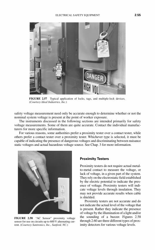
safety voltage measurement need only be accurate enough to determine whether or not thenominal system voltage is present at the point of worker exposure.
The instruments discussed in the following sections are intended primarily for safetyvoltage measurements. Some of them are quite accurate. Contact the individual manufac-turers for more specific information.
For various reasons, some authorities prefer a proximity tester over a contact tester, whileothers prefer a contact tester over a proximity tester. Whichever type is selected, it must becapable of indicating the presence of dangerous voltages and discriminating between nuisancestatic voltages and actual hazardous voltage source. See Chap. 3 for more information.
Proximity Testers
Proximity testers do not require actual metal-to-metal contact to measure the voltage, orlack of voltage, in a given part of the system.They rely on the electrostatic field establishedby the electric potential to indicate the pres-ence of voltage. Proximity testers will indi-cate voltage levels through insulation. Theymay not provide accurate results when cableis shielded.
Proximity testers are not accurate and donot indicate the actual level of the voltage thatis present. Rather they indicate the presenceof voltage by the illumination of a light and/orthe sounding of a buzzer. Figures 2.58through 2.60 are three different types of prox-imity detectors for various voltage levels.
ELECTRICAL SAFETY EQUIPMENT 2.55
FIGURE 2.57 Typical application of locks, tags, and multiple-lock devices.(Courtesy Ideal Industries, Inc.)
FIGURE 2.58 “AC Sensor” proximity voltagesensor for use on circuits up to 600 V alternating cur-rent. (Courtesy Santronics, Inc., Sanford, NC.)
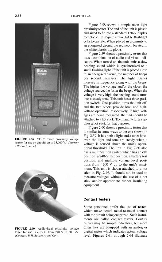
2.56 CHAPTER TWO
Figure 2.58 shows a simple neon lightproximity tester. The end of the unit is plasticand sized to fit into a standard 120-V duplexreceptacle. It requires two AAA flashlightcells to operate. When placed in proximity toan energized circuit, the red neon, located inthe white plastic tip, glows.
Figure 2.59 shows a proximity tester thatuses a combination of audio and visual indi-cators. When turned on, the unit emits a slowbeeping sound which is synchronized to asmall flashing light. If the unit is placed closeto an energized circuit, the number of beepsper second increases. The light flashesincrease in frequency along with the beeps.The higher the voltage and/or the closer thevoltage source, the faster the beeps. When thevoltage is very high, the beeping sound turnsinto a steady tone. This unit has a three-posi-tion switch. One position turns the unit off,and the two others provide low- and high-voltage operation, respectively. If high volt-ages are being measured, the unit should beattached to a hot stick. The manufacturer sup-plies a hot stick for that purpose.
Figure 2.60 shows a proximity tester thatis similar in some ways to the one shown inFig. 2.59. It has both a light and a tone; how-ever, the light and tone are steady when avoltage is sensed above the unit’s opera-tional threshold. The unit in Fig. 2.60 alsohas a multiposition switch which has an OFF
position, a 240-V test position, a battery testposition, and multiple voltage level posi-tions from 4200 V up to the unit’s maxi-mum. This unit is shown attached to a hotstick in Fig. 2.46. It should not be used tomeasure voltages without the use of a hotstick and/or appropriate rubber insulatingequipment.
Contact Testers
Some personnel prefer the use of testerswhich make actual metal-to-metal contactwith the circuit being energized. Such instru-ments are called contact testers. Contacttesters may be simple indicators, but moreoften they are equipped with an analog ordigital meter which indicates actual voltagelevel. Figures 2.61 through 2.64 illustrate
FIGURE 2.59 “TIC” tracer proximity voltagesensor for use on circuits up to 35,000 V. (CourtesyTIF Electronics.)
FIGURE 2.60 Audiovisual proximity voltagetester for use in circuits from 240 V to 500 kV.(Courtesy W.H. Salisbury and Co.)
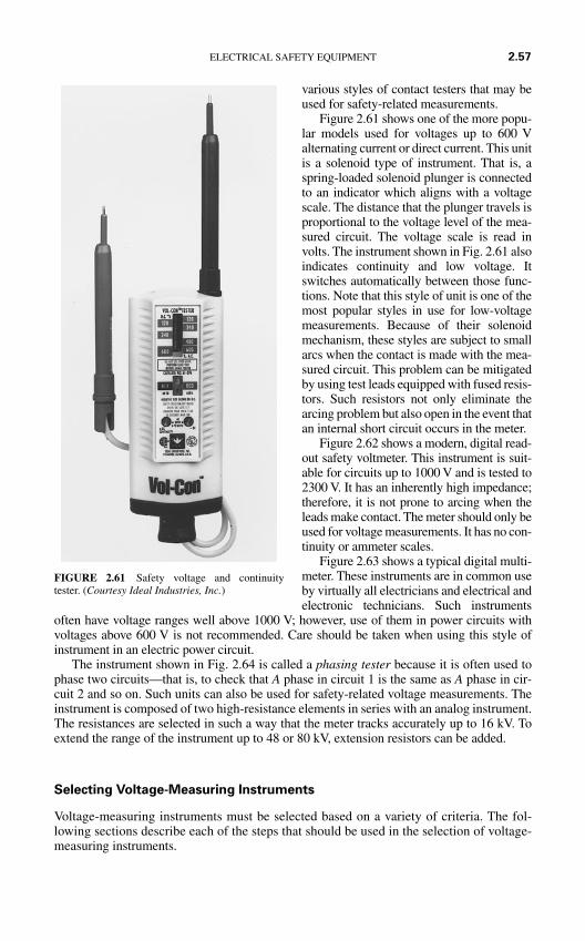
various styles of contact testers that may beused for safety-related measurements.
Figure 2.61 shows one of the more popu-lar models used for voltages up to 600 Valternating current or direct current. This unitis a solenoid type of instrument. That is, aspring-loaded solenoid plunger is connectedto an indicator which aligns with a voltagescale. The distance that the plunger travels isproportional to the voltage level of the mea-sured circuit. The voltage scale is read involts. The instrument shown in Fig. 2.61 alsoindicates continuity and low voltage. Itswitches automatically between those func-tions. Note that this style of unit is one of themost popular styles in use for low-voltagemeasurements. Because of their solenoidmechanism, these styles are subject to smallarcs when the contact is made with the mea-sured circuit. This problem can be mitigatedby using test leads equipped with fused resis-tors. Such resistors not only eliminate thearcing problem but also open in the event thatan internal short circuit occurs in the meter.
Figure 2.62 shows a modern, digital read-out safety voltmeter. This instrument is suit-able for circuits up to 1000 V and is tested to2300 V. It has an inherently high impedance;therefore, it is not prone to arcing when theleads make contact. The meter should only beused for voltage measurements. It has no con-tinuity or ammeter scales.
Figure 2.63 shows a typical digital multi-meter. These instruments are in common useby virtually all electricians and electrical andelectronic technicians. Such instruments
often have voltage ranges well above 1000 V; however, use of them in power circuits withvoltages above 600 V is not recommended. Care should be taken when using this style ofinstrument in an electric power circuit.
The instrument shown in Fig. 2.64 is called a phasing tester because it is often used tophase two circuits—that is, to check that A phase in circuit 1 is the same as A phase in cir-cuit 2 and so on. Such units can also be used for safety-related voltage measurements. Theinstrument is composed of two high-resistance elements in series with an analog instrument.The resistances are selected in such a way that the meter tracks accurately up to 16 kV. Toextend the range of the instrument up to 48 or 80 kV, extension resistors can be added.
Selecting Voltage-Measuring Instruments
Voltage-measuring instruments must be selected based on a variety of criteria. The fol-lowing sections describe each of the steps that should be used in the selection of voltage-measuring instruments.
ELECTRICAL SAFETY EQUIPMENT 2.57
FIGURE 2.61 Safety voltage and continuitytester. (Courtesy Ideal Industries, Inc.)
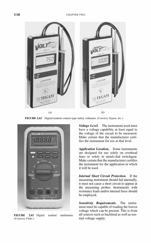
2.58 CHAPTER TWO
Voltage Level. The instrument used musthave a voltage capability at least equal tothe voltage of the circuit to be measured.Make certain that the manufacturer certi-fies the instrument for use at that level.
Application Location. Some instrumentsare designed for use solely on overheadlines or solely in metal-clad switchgear.Make certain that the manufacturer certifiesthe instrument for the application in whichit will be used.
Internal Short Circuit Protection. If themeasuring instrument should fail internally,it must not cause a short circuit to appear atthe measuring probes. Instruments withresistance leads and/or internal fuses shouldbe employed.
Sensitivity Requirements. The instru-ment must be capable of reading the lowestvoltage which can be present. This is fromall sources such as backfeed as well as nor-mal voltage supply.
(a) (b)
FIGURE 2.62 Digital readout contact-type safety voltmeter. (Courtesy Tegam, Inc.)
FIGURE 2.63 Digital readout multimeter.(Courtesy Fluke.)
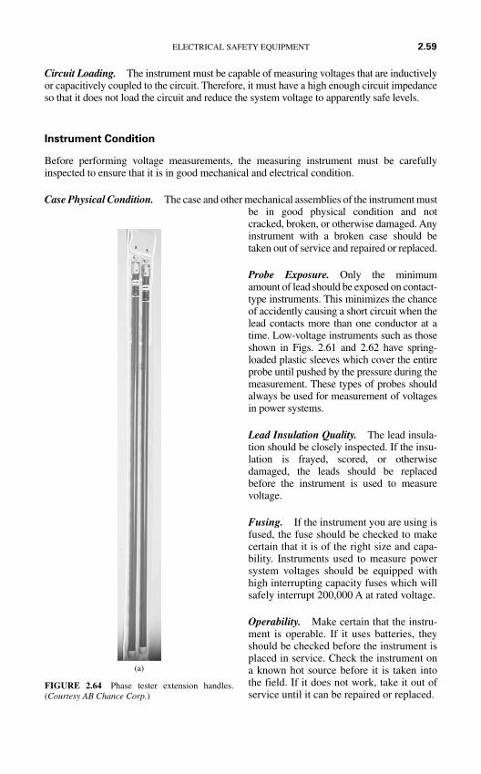
Circuit Loading. The instrument must be capable of measuring voltages that are inductivelyor capacitively coupled to the circuit. Therefore, it must have a high enough circuit impedanceso that it does not load the circuit and reduce the system voltage to apparently safe levels.
Instrument Condition
Before performing voltage measurements, the measuring instrument must be carefullyinspected to ensure that it is in good mechanical and electrical condition.
Case Physical Condition. The case and other mechanical assemblies of the instrument mustbe in good physical condition and notcracked, broken, or otherwise damaged. Anyinstrument with a broken case should betaken out of service and repaired or replaced.
Probe Exposure. Only the minimumamount of lead should be exposed on contact-type instruments. This minimizes the chanceof accidently causing a short circuit when thelead contacts more than one conductor at atime. Low-voltage instruments such as thoseshown in Figs. 2.61 and 2.62 have spring-loaded plastic sleeves which cover the entireprobe until pushed by the pressure during themeasurement. These types of probes shouldalways be used for measurement of voltagesin power systems.
Lead Insulation Quality. The lead insula-tion should be closely inspected. If the insu-lation is frayed, scored, or otherwisedamaged, the leads should be replacedbefore the instrument is used to measurevoltage.
Fusing. If the instrument you are using isfused, the fuse should be checked to makecertain that it is of the right size and capa-bility. Instruments used to measure powersystem voltages should be equipped withhigh interrupting capacity fuses which willsafely interrupt 200,000 A at rated voltage.
Operability. Make certain that the instru-ment is operable. If it uses batteries, theyshould be checked before the instrument isplaced in service. Check the instrument ona known hot source before it is taken intothe field. If it does not work, take it out ofservice until it can be repaired or replaced.
ELECTRICAL SAFETY EQUIPMENT 2.59
(a)
FIGURE 2.64 Phase tester extension handles.(Courtesy AB Chance Corp.)
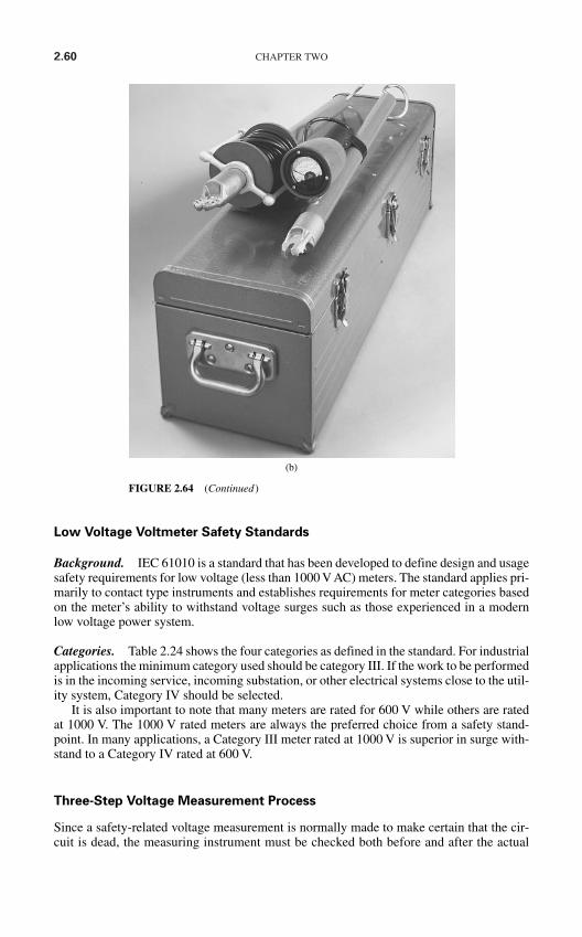
2.60 CHAPTER TWO
Low Voltage Voltmeter Safety Standards
Background. IEC 61010 is a standard that has been developed to define design and usagesafety requirements for low voltage (less than 1000 V AC) meters. The standard applies pri-marily to contact type instruments and establishes requirements for meter categories basedon the meter’s ability to withstand voltage surges such as those experienced in a modernlow voltage power system.
Categories. Table 2.24 shows the four categories as defined in the standard. For industrialapplications the minimum category used should be category III. If the work to be performedis in the incoming service, incoming substation, or other electrical systems close to the util-ity system, Category IV should be selected.
It is also important to note that many meters are rated for 600 V while others are ratedat 1000 V. The 1000 V rated meters are always the preferred choice from a safety stand-point. In many applications, a Category III meter rated at 1000 V is superior in surge with-stand to a Category IV rated at 600 V.
Three-Step Voltage Measurement Process
Since a safety-related voltage measurement is normally made to make certain that the cir-cuit is dead, the measuring instrument must be checked both before and after the actual
(b)
FIGURE 2.64 (Continued)
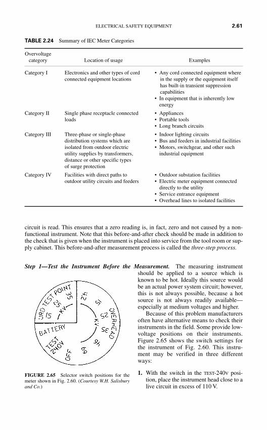
circuit is read. This ensures that a zero reading is, in fact, zero and not caused by a non-functional instrument. Note that this before-and-after check should be made in addition tothe check that is given when the instrument is placed into service from the tool room or sup-ply cabinet. This before-and-after measurement process is called the three-step process.
Step 1—Test the Instrument Before the Measurement. The measuring instrumentshould be applied to a source which isknown to be hot. Ideally this source wouldbe an actual power system circuit; however,this is not always possible, because a hotsource is not always readily available—especially at medium voltages and higher.
Because of this problem manufacturersoften have alternative means to check theirinstruments in the field. Some provide low-voltage positions on their instruments.Figure 2.65 shows the switch settings forthe instrument of Fig. 2.60. This instru-ment may be verified in three differentways:
1. With the switch in the TEST-240V posi-tion, place the instrument head close to alive circuit in excess of 110 V.
ELECTRICAL SAFETY EQUIPMENT 2.61
FIGURE 2.65 Selector switch positions for themeter shown in Fig. 2.60. (Courtesy W.H. Salisburyand Co.)
TABLE 2.24 Summary of IEC Meter Categories
Overvoltagecategory Location of usage Examples
Category I Electronics and other types of cord • Any cord connected equipment where connected equipment locations in the supply or the equipment itself
has built-in transient suppressioncapabilities
• In equipment that is inherently low energy
Category II Single phase receptacle connected • Appliancesloads • Portable tools
• Long branch circuits
Category III Three-phase or single-phase • Indoor lighting circuitsdistribution systems which are • Bus and feeders in industrial facilitiesisolated from outdoor electric • Motors, switchgear, and other such utility supplies by transformers, industrial equipmentdistance or other specific types of surge protection
Category IV Facilities with direct paths to • Outdoor substation facilitiesoutdoor utility circuits and feeders • Electric meter equipment connected
directly to the utility• Service entrance equipment• Overhead lines to isolated facilities
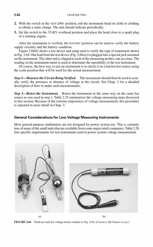
2. With the switch in the TEST-240V position, rub the instrument head on cloth or clothingto obtain a static charge. The unit should indicate periodically.
3. Set the switch to the 35-KV overhead position and place the head close to a spark plugof a running engine.
After the instrument is verified, the BATTERY position can be used to verify the batterysupply circuitry and the battery condition.
Figure 2.66(b) shows a test device and setup used to verify the type of instrument shownin Fig. 2.64. One lead from the test device (Fig. 2.66(a)) is plugged into a special jack mountedon the instrument. The other end is clipped to each of the measuring probes, one at a time. Thereading on the instrument meter is used to determine the operability of the test instrument.
Of course, the best way to test an instrument is to check it on a known hot source usingthe scale position that will be used for the actual measurement.
Step 2—Measure the Circuit Being Verified. The instrument should then be used to actu-ally verify the presence or absence of voltage in the circuit. See Chap. 3 for a detaileddescription of how to make such measurements.
Step 3—Retest the Instrument. Retest the instrument in the same way on the same hotsource as was used in step 1. Table 2.25 summarizes the voltage-measuring steps discussedin this section. Because of the extreme importance of voltage measurement, this procedureis repeated in more detail in Chap. 3.
General Considerations for Low-Voltage Measuring Instruments
Most general-purpose multimeters are not designed for power system use. This is certainlytrue of many of the small units that are available from some major retail companies. Table 2.26lists specific requirements for test instruments used in power system voltage measurement.
2.62 CHAPTER TWO
(a) (b)
FIGURE 2.66 Field test unit for voltage testers similar to Fig. 2.64. (Courtesy AB Chance Corp.)
ELECTRICAL SAFETY EQUIPMENT 2.63
SAFETY GROUNDING EQUIPMENT
The Need for Safety Grounding
Even circuits that have been properly locked and tagged can be accidently energized whilepersonnel are working on or near exposed conductors. For example,
If capacitors are not discharged and grounded, they could accidently be connected to thesystem.
Voltages could be induced from adjacent circuits. Such voltages can be extremely high ifthe adjacent circuit experiences a short circuit.
Switching errors could result in reenergizing of the circuit. An energized conductor can fall or be forced into the de-energized circuit, thereby ener-
gizing it and causing injury. Lightning strikes could induce extremely high voltages in the conductors.
Instrument selection • Voltage level• Application location• Internal short circuit protection• Sensitivity requirements• Circuit loading
Instrument condition • Case physical condition• Probe exposure• Lead insulation quality• Fusing• Operability
Three-step process • Check the meter• Check the circuit• Check the meter
* See text for details.
TABLE 2.25 Voltage Measuring Instrument Selection and Use*
Instrument should be certified for use in electric power systemsLeads should be of proper design
Secured permanently to instrumentFully insulated probes with minimum metallic exposureInsulation rated for voltage of circuits to be measured
Internal fusing capable of interrupting fault current if short circuit occursHigh resistance measurement to minimize arcing at probe tipsSingle-function (voltage readings) instrument preferred
If a multimeter is used, the resistance and current measurement circuits must be adequately fusedAuto-voltage detection is desirable
Instrument insulation levels should be rated for voltage of the circuits to be measuredInstrument should be the correct category for the application per IEC 61010.
TABLE 2.26 Checklist for Low-Voltage Measuring Equipment
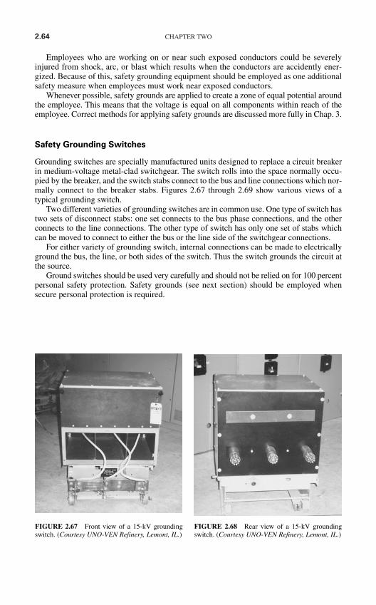
2.64 CHAPTER TWO
Employees who are working on or near such exposed conductors could be severelyinjured from shock, arc, or blast which results when the conductors are accidently ener-gized. Because of this, safety grounding equipment should be employed as one additionalsafety measure when employees must work near exposed conductors.
Whenever possible, safety grounds are applied to create a zone of equal potential aroundthe employee. This means that the voltage is equal on all components within reach of theemployee. Correct methods for applying safety grounds are discussed more fully in Chap. 3.
Safety Grounding Switches
Grounding switches are specially manufactured units designed to replace a circuit breakerin medium-voltage metal-clad switchgear. The switch rolls into the space normally occu-pied by the breaker, and the switch stabs connect to the bus and line connections which nor-mally connect to the breaker stabs. Figures 2.67 through 2.69 show various views of atypical grounding switch.
Two different varieties of grounding switches are in common use. One type of switch hastwo sets of disconnect stabs: one set connects to the bus phase connections, and the otherconnects to the line connections. The other type of switch has only one set of stabs whichcan be moved to connect to either the bus or the line side of the switchgear connections.
For either variety of grounding switch, internal connections can be made to electricallyground the bus, the line, or both sides of the switch. Thus the switch grounds the circuit atthe source.
Ground switches should be used very carefully and should not be relied on for 100 percentpersonal safety protection. Safety grounds (see next section) should be employed whensecure personal protection is required.
FIGURE 2.67 Front view of a 15-kV groundingswitch. (Courtesy UNO-VEN Refinery, Lemont, IL.)
FIGURE 2.68 Rear view of a 15-kV groundingswitch. (Courtesy UNO-VEN Refinery, Lemont, IL.)
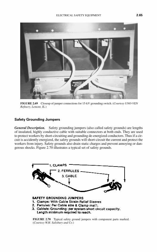
Safety Grounding Jumpers
General Description. Safety grounding jumpers (also called safety grounds) are lengthsof insulated, highly conductive cable with suitable connectors at both ends. They are usedto protect workers by short-circuiting and grounding de-energized conductors. Thus if a cir-cuit is accidently energized, the safety grounds will short-circuit the current and protect theworkers from injury. Safety grounds also drain static charges and prevent annoying or dan-gerous shocks. Figure 2.70 illustrates a typical set of safety grounds.
ELECTRICAL SAFETY EQUIPMENT 2.65
FIGURE 2.70 Typical safety ground jumpers with component parts marked.(Courtesy W.H. Salisbury and Co.)
FIGURE 2.69 Closeup of jumper connections for 15-kV grounding switch. (Courtesy UNO-VENRefinery, Lemont, IL.)
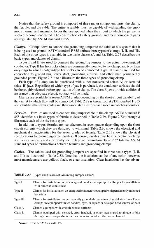
Notice that the safety ground is composed of three major component parts: the clamp,the ferrule, and the cable. The entire assembly must be capable of withstanding the enor-mous thermal and magnetic forces that are applied when the circuit to which the jumper isapplied becomes energized. The construction of safety grounds and their component partsare regulated by ASTM standard F 855.
Clamps. Clamps serve to connect the grounding jumper to the cable or bus system that itis being used to ground. ASTM standard F 855 defines three types of clamps (I, II, and III).Each of the three types is available in two basic classes (A and B). Table 2.27 describes thebasic types and classes of clamp.
Types I and II are used to connect the grounding jumper to the actual de-energizedconductor. Type II has hot sticks which are permanently mounted to the clamp, and type I hasonly rings to which shotgun-type hot sticks can be connected. Type III clamps are used forconnection to ground bus, tower steel, grounding clusters, and other such permanentlygrounded points. Figure 2.71a to c illustrates the three types of grounding clamp.
Each type of clamp can be purchased with either nonserrated (class A) or serrated(class B) jaws. Regardless of which type of jaw is purchased, the conductor surfaces shouldbe thoroughly cleaned before application of the clamp. The class B jaws provide additionalassurance that adequate electric contact will be made.
Clamps are available in seven ASTM grades depending on the short-circuit capability ofthe circuit to which they will be connected. Table 2.28 is taken from ASTM standard F 855and identifies the seven grades and their associated electrical and mechanical characteristics.
Ferrules. Ferrules are used to connect the jumper cable to the clamp. ASTM standard F855 identifies six basic types of ferrule as described in Table 2.29. Figure 2.72a through dillustrates each of the six basic types.
In addition to types, ferrules are manufactured in seven grades depending upon the shortcircuit currents which they are designed to withstand. Table 2.30 shows the electrical andmechanical characteristics for the seven grades of ferrule. Table 2.31 shows the physicalspecifications for grounding cable ferrules. Of course, ferrules must be attached to the clampwith a mechanically and electrically secure type of termination. Table 2.32 lists the ASTMstandard types of terminations between ferrules and grounding clamps.
Cables. The cables used for grounding jumpers are specified in three basic types (I, II,and III) as illustrated in Table 2.33. Note that the insulation can be of any color; however,most manufacturers use yellow, black, or clear insulation. Clear insulation has the advan-
2.66 CHAPTER TWO
Type I Clamps for installation on de-energized conductors equipped with eyes for installationwith removable hot sticks
Type II Clamps for installation on de-energized conductors equipped with permanently mountedhot sticks
Type III Clamps for installation on permanently grounded conductors of metal structures.Theseclamps are equipped with tee handles, eyes, or square or hexagon head screws, or both
Class A Clamps equipped with smooth contact surfaces
Class B Clamps equipped with serrated, cross-hatched, or other means used to abrade or bitethrough corrosion products on the conductor to which the jaw is clamped
Source: From ASTM Standard F 855.
TABLE 2.27 Types and Classes of Grounding Jumper Clamps
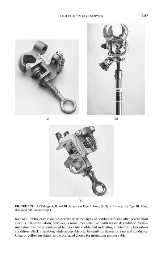
ELECTRICAL SAFETY EQUIPMENT 2.67
tage of allowing easy visual inspection to detect signs of conductor fusing after severe shortcircuits. Clear insulation, however, is sometimes sensitive to ultraviolet degradation. Yellowinsulation has the advantage of being easily visible and indicating a potentially hazardouscondition. Black insulation, while acceptable, can be easily mistaken for a normal conductor.Clear or yellow insulation is the preferred choice for grounding jumper cable.
(a) (b)
(c)
FIGURE 2.71 ASTM type I, II, and III clamps. (a) Type I clamp; (b) Type II clamp; (c) Type III clamp.(Courtesy AB Chance Corp.)
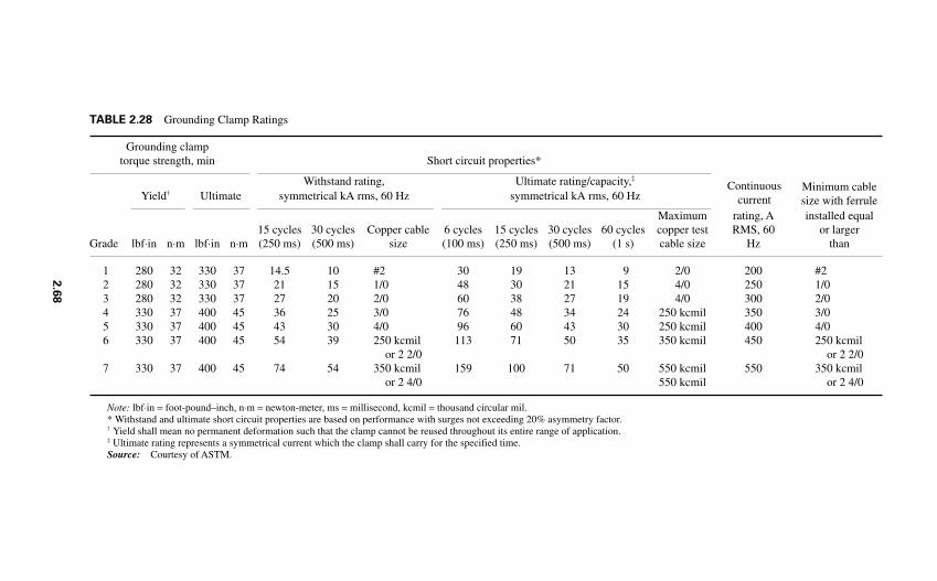
Grounding clamp torque strength, min Short circuit properties*
Withstand rating, Ultimate rating/capacity,‡
Yield† Ultimate symmetrical kA rms, 60 Hz symmetrical kA rms, 60 Hz
Maximum rating, A installed equal15 cycles 30 cycles Copper cable 6 cycles 15 cycles 30 cycles 60 cycles copper test RMS, 60 or larger
Grade lbf⋅in n⋅m lbf⋅in n⋅m (250 ms) (500 ms) size (100 ms) (250 ms) (500 ms) (1 s) cable size Hz than
1 280 32 330 37 14.5 10 #2 30 19 13 9 2/0 200 #22 280 32 330 37 21 15 1/0 48 30 21 15 4/0 250 1/03 280 32 330 37 27 20 2/0 60 38 27 19 4/0 300 2/04 330 37 400 45 36 25 3/0 76 48 34 24 250 kcmil 350 3/05 330 37 400 45 43 30 4/0 96 60 43 30 250 kcmil 400 4/06 330 37 400 45 54 39 250 kcmil 113 71 50 35 350 kcmil 450 250 kcmil
or 2 2/0 or 2 2/07 330 37 400 45 74 54 350 kcmil 159 100 71 50 550 kcmil 550 350 kcmil
or 2 4/0 550 kcmil or 2 4/0
Note: lbf⋅in = foot-pound–inch, n⋅m = newton-meter, ms = millisecond, kcmil = thousand circular mil.* Withstand and ultimate short circuit properties are based on performance with surges not exceeding 20% asymmetry factor.† Yield shall mean no permanent deformation such that the clamp cannot be reused throughout its entire range of application.‡ Ultimate rating represents a symmetrical current which the clamp shall carry for the specified time.Source: Courtesy of ASTM.
TABLE 2.28 Grounding Clamp Ratings
Minimum cablesize with ferrule
Continuouscurrent
2.6
8
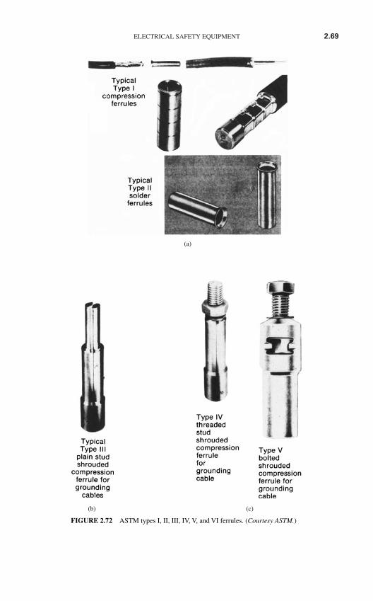
ELECTRICAL SAFETY EQUIPMENT 2.69
(b) (c)
(a)
FIGURE 2.72 ASTM types I, II, III, IV, V, and VI ferrules. (Courtesy ASTM.)
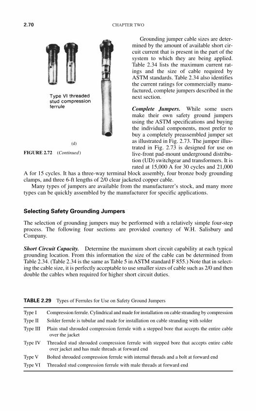
2.70 CHAPTER TWO
Grounding jumper cable sizes are deter-mined by the amount of available short cir-cuit current that is present in the part of thesystem to which they are being applied.Table 2.34 lists the maximum current rat-ings and the size of cable required byASTM standards. Table 2.34 also identifiesthe current ratings for commercially manu-factured, complete jumpers described in thenext section.
Complete Jumpers. While some usersmake their own safety ground jumpersusing the ASTM specifications and buyingthe individual components, most prefer tobuy a completely preassembled jumper setas illustrated in Fig. 2.73. The jumper illus-trated in Fig. 2.73 is designed for use onlive-front pad-mount underground distribu-tion (UD) switchgear and transformers. It israted at 15,000 A for 30 cycles and 21,000
A for 15 cycles. It has a three-way terminal block assembly, four bronze body groundingclamps, and three 6-ft lengths of 2/0 clear jacketed copper cable.
Many types of jumpers are available from the manufacturer’s stock, and many moretypes can be quickly assembled by the manufacturer for specific applications.
Selecting Safety Grounding Jumpers
The selection of grounding jumpers may be performed with a relatively simple four-stepprocess. The following four sections are provided courtesy of W.H. Salisbury andCompany.
Short Circuit Capacity. Determine the maximum short circuit capability at each typicalgrounding location. From this information the size of the cable can be determined fromTable 2.34. (Table 2.34 is the same as Table 5 in ASTM standard F 855.) Note that in select-ing the cable size, it is perfectly acceptable to use smaller sizes of cable such as 2/0 and thendouble the cables when required for higher short circuit duties.
(d)
FIGURE 2.72 (Continued)
Type I Compression ferrule. Cylindrical and made for installation on cable stranding by compression
Type II Solder ferrule is tubular and made for installation on cable stranding with solder
Type III Plain stud shrouded compression ferrule with a stepped bore that accepts the entire cableover the jacket
Type IV Threaded stud shrouded compression ferrule with stepped bore that accepts entire cableover jacket and has male threads at forward end
Type V Bolted shrouded compression ferrule with internal threads and a bolt at forward end
Type VI Threaded stud compression ferrule with male threads at forward end
TABLE 2.29 Types of Ferrules for Use on Safety Ground Jumpers
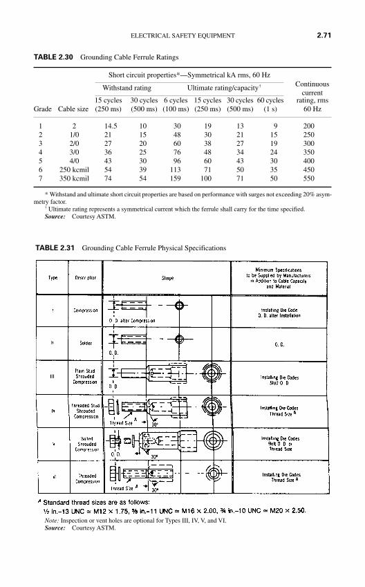
ELECTRICAL SAFETY EQUIPMENT 2.71
Short circuit properties*—Symmetrical kA rms, 60 Hz
Withstand rating Ultimate rating/capacity†
15 cycles 30 cycles 6 cycles 15 cycles 30 cycles 60 cycles rating, rmsGrade Cable size (250 ms) (500 ms) (100 ms) (250 ms) (500 ms) (1 s) 60 Hz
1 2 14.5 10 30 19 13 9 2002 1/0 21 15 48 30 21 15 2503 2/0 27 20 60 38 27 19 3004 3/0 36 25 76 48 34 24 3505 4/0 43 30 96 60 43 30 4006 250 kcmil 54 39 113 71 50 35 4507 350 kcmil 74 54 159 100 71 50 550
* Withstand and ultimate short circuit properties are based on performance with surges not exceeding 20% asym-metry factor.
† Ultimate rating represents a symmetrical current which the ferrule shall carry for the time specified.Source: Courtesy ASTM.
TABLE 2.30 Grounding Cable Ferrule Ratings
Continuouscurrent
TABLE 2.31 Grounding Cable Ferrule Physical Specifications
Note: Inspection or vent holes are optional for Types III, IV, V, and VI.Source: Courtesy ASTM.
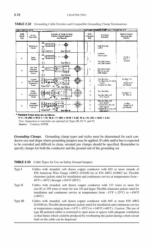
2.72 CHAPTER TWO
TABLE 2.32 Grounding Cable Ferrules and Compatible Grounding Clamp Terminations
Note: Inspection or vent holes are optional for Types III, IV, V, and VI.Source: Courtesy ASTM.
Type I Cables with stranded, soft drawn copper conductor with 665 or more strands of#30 American Wire Gauge (AWG) (0.0100 in) or #34 AWG (0.0063 in). Flexibleelastomer jackets rated for installation and continuous service at temperatures from −40°F (−40°C) through +194°F (90°C)
Type II Cables with stranded, soft drawn copper conductor with 133 wires or more forsize #2 or 259 wires or more for size 1/0 and larger. Flexible elastomer jackets rated forinstallation and continuous service at temperatures from −13°F (−25°C) to +194°F(+90°C)
Type III Cables with stranded, soft drawn copper conductor with 665 or more #30 AWG(0.0100 in). Flexible thermoplastic jackets rated for installation and continuous serviceat temperatures ranging from +14°F (−10°C) to +140°F (+60°C). Caution: The use oftype III jacketed cables is restricted to open areas or spaces with adequate ventilationso that fumes which could be produced by overheating the jacket during a short circuitfault on the cable can be dispersed
TABLE 2.33 Cable Types for Use on Safety Ground Jumpers
Grounding Clamps. Grounding clamp types and styles must be determined for each con-ductor size and shape where grounding jumpers may be applied. If cable and/or bus is expectedto be corroded and difficult to clean, serrated jaw clamps should be specified. Remember tospecify clamps for both the conductor and the ground end of the grounding set.
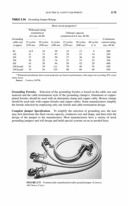
Grounding Ferrules. Selection of the grounding ferrules is based on the cable size andmaterial and the cable termination style of the grounding clamp(s). Aluminum or copper-plated ferrules should be used with an aluminum clamp and copper cable. Bronze clampsshould be used only with copper ferrules and copper cables. Some manufacturers simplifythe ferrule selection by employing only one ferrule and cable termination design.
Complete Jumper Specification. To simplify the selection of grounding sets, the usermay first determine the short circuit capacity, conductor size and shape, and then refer thedesign of the jumper to the manufacturer. Most manufacturers have a variety of stockgrounding jumpers and will design and build special systems on an as-needed basis.
ELECTRICAL SAFETY EQUIPMENT 2.73
FIGURE 2.73 Commercially manufactured safety ground jumper. (CourtesyAB Chance Corp.)
TABLE 2.34 Grounding Jumper Ratings
Short circuit properties*
Withstand-rating symmetrical Ultimate capacity
kA rms, 60 Hz symmetrical kA rms, 60 HzGrounding Continuouscable size 15 cycles 30 cycles 6 cycles 15 cycles 30 cycles 60 cycles current rating,(copper) (250 ms) (500 ms) (100 ms) (250 ms) (500 ms) (1 s) rms, 60 Hz
#2 14.5 10 29 18 13 9 2001/0 21 15 47 29 21 14 2502/0 27 20 59 37 26 18 3003/0 36 25 74 47 33 23 3504/0 43 30 94 59 42 29 400250 kcmil 54 39 111 70 49 35 450350 kcmil 74 54 155 98 69 49 550
* Withstand and ultimate short circuit properties are based on performance with surges not exceeding 20% asym-metry factor.
Source: Courtesy ASTM.
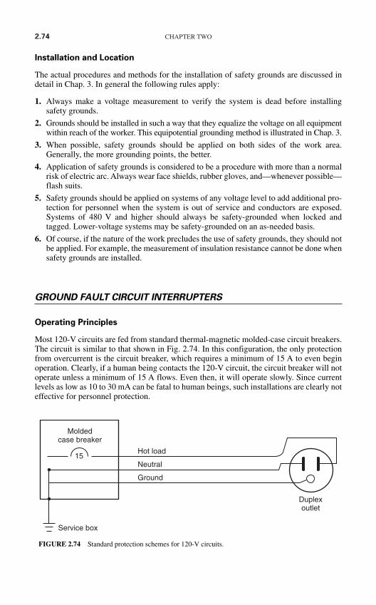
2.74 CHAPTER TWO
Installation and Location
The actual procedures and methods for the installation of safety grounds are discussed indetail in Chap. 3. In general the following rules apply:
1. Always make a voltage measurement to verify the system is dead before installingsafety grounds.
2. Grounds should be installed in such a way that they equalize the voltage on all equipmentwithin reach of the worker. This equipotential grounding method is illustrated in Chap. 3.
3. When possible, safety grounds should be applied on both sides of the work area.Generally, the more grounding points, the better.
4. Application of safety grounds is considered to be a procedure with more than a normalrisk of electric arc. Always wear face shields, rubber gloves, and—whenever possible—flash suits.
5. Safety grounds should be applied on systems of any voltage level to add additional pro-tection for personnel when the system is out of service and conductors are exposed.Systems of 480 V and higher should always be safety-grounded when locked andtagged. Lower-voltage systems may be safety-grounded on an as-needed basis.
6. Of course, if the nature of the work precludes the use of safety grounds, they should notbe applied. For example, the measurement of insulation resistance cannot be done whensafety grounds are installed.
GROUND FAULT CIRCUIT INTERRUPTERS
Operating Principles
Most 120-V circuits are fed from standard thermal-magnetic molded-case circuit breakers.The circuit is similar to that shown in Fig. 2.74. In this configuration, the only protectionfrom overcurrent is the circuit breaker, which requires a minimum of 15 A to even beginoperation. Clearly, if a human being contacts the 120-V circuit, the circuit breaker will notoperate unless a minimum of 15 A flows. Even then, it will operate slowly. Since currentlevels as low as 10 to 30 mA can be fatal to human beings, such installations are clearly noteffective for personnel protection.
Moldedcase breaker
Service box
Hot load
Neutral
Ground
Duplexoutlet
15
FIGURE 2.74 Standard protection schemes for 120-V circuits.
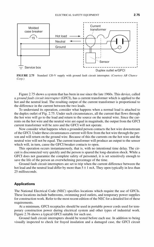
Figure 2.75 shows a system that has been in use since the late 1960s. This device, calleda ground fault circuit interrupter (GFCI), has a current transformer which is applied to thehot and the neutral lead. The resulting output of the current transformer is proportional tothe difference in the current between the two leads.
To understand its operation, consider what happens when a normal load is attached tothe duplex outlet of Fig. 2.75. Under such circumstances, all the current that flows throughthe hot wire will go to the load and return to the source on the neutral wire. Since the cur-rents on the hot wire and the neutral wire are equal in magnitude, the output from the GFCIcurrent transformer will be zero and the GFCI will not operate.
Now consider what happens when a grounded person contacts the hot wire downstreamof the GFCI. Under these circumstances current will flow from the hot wire through the per-son and will return on the ground wire. Because of this the currents on the hot wire and theneutral wire will not be equal. The current transformer will produce an output to the sensorwhich will, in turn, cause the GFCI breaker contacts to open.
This operation occurs instantaneously, that is, with no intentional time delay. The cir-cuit is disconnected very quickly and the person is spared the long-duration shock. While aGFCI does not guarantee the complete safety of personnel, it is set sensitively enough tosave the life of the person an overwhelming percentage of the time.
Ground fault circuit interrupters are set to trip when the current difference between thehot lead and the neutral lead differ by more than 5 ± 1 mA. They open typically in less than25 milliseconds.
Applications
The National Electrical Code (NEC) specifies locations which require the use of GFCIs.These locations include bathrooms, swimming pool outlets, and temporary power suppliesfor construction work. Refer to the most recent edition of the NEC for a detailed list of theserequirements.
At a minimum, GFCI receptacles should be used in portable power cords used for tem-porary construction power during electrical system and other types of industrial work.Figure 2.76 shows a typical GFCI suitable for such use.
Ground fault circuit interrupters should be tested before each use. In addition to beingvisually inspected to check for frayed insulation and a damaged case, the GFCI circuit
ELECTRICAL SAFETY EQUIPMENT 2.75
Moldedcase breaker
Service box
Hot load
Neutral
Ground
15
Currenttransformer
Sensor
Duplex outlet w/GFCI
FIGURE 2.75 Standard 120-V supply with ground fault circuit interrupter. (Courtesy AB ChanceCorp.)
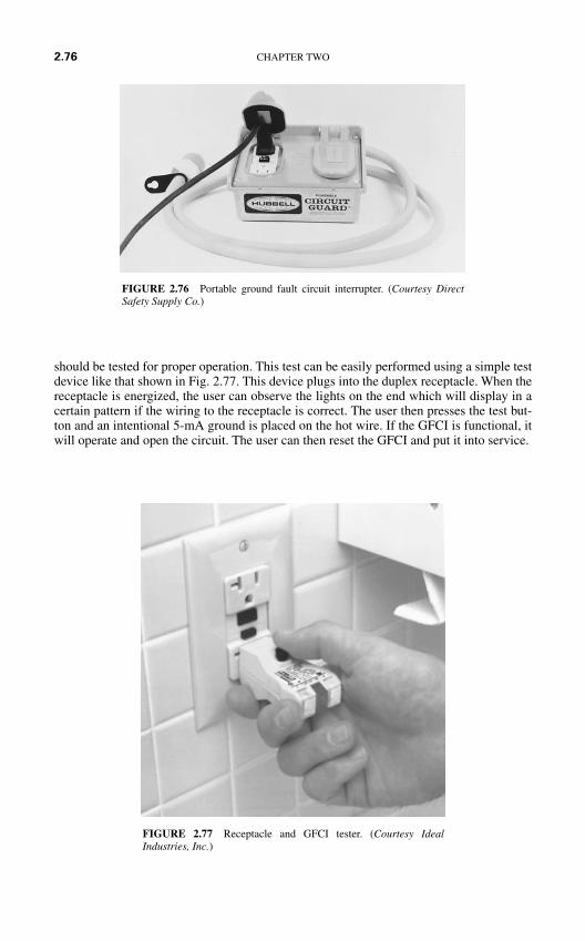
should be tested for proper operation. This test can be easily performed using a simple testdevice like that shown in Fig. 2.77. This device plugs into the duplex receptacle. When thereceptacle is energized, the user can observe the lights on the end which will display in acertain pattern if the wiring to the receptacle is correct. The user then presses the test but-ton and an intentional 5-mA ground is placed on the hot wire. If the GFCI is functional, itwill operate and open the circuit. The user can then reset the GFCI and put it into service.
2.76 CHAPTER TWO
FIGURE 2.77 Receptacle and GFCI tester. (Courtesy IdealIndustries, Inc.)
FIGURE 2.76 Portable ground fault circuit interrupter. (Courtesy DirectSafety Supply Co.)
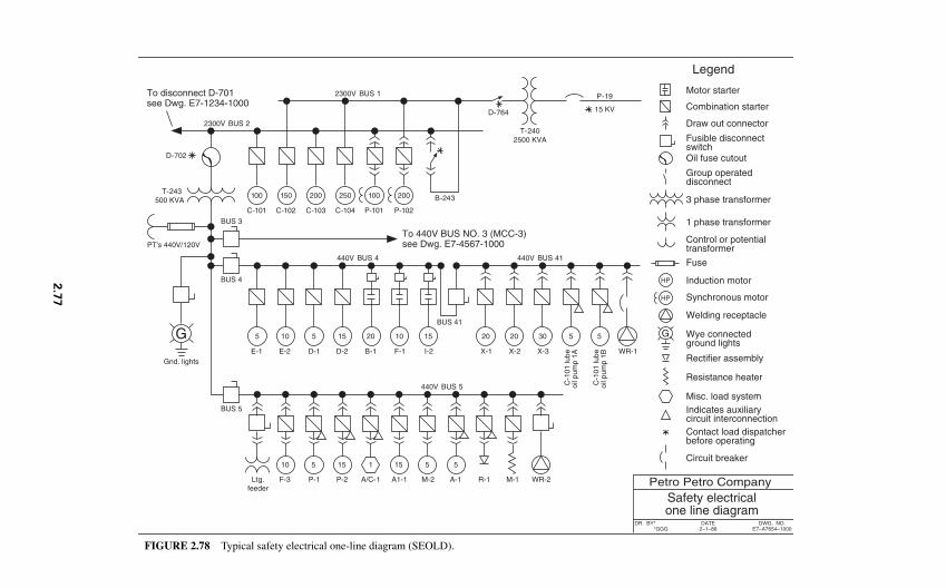
G G
Motor starter
3 phase transformer
Combination starter
Draw out connector
Fusible disconnectswitchOil fuse cutout
Group operateddisconnect
1 phase transformer
Control or potentialtransformer
Fuse
Induction motor
Synchronous motor
Welding receptacle
Wye connectedground lights
Rectifier assembly
Resistance heater
Misc. load system Indicates auxiliary circuit interconnectionContact load dispatcherbefore operating
Circuit breaker
Petro Petro CompanySafety electricalone line diagram
DR. BY**GGG
DATE2–1–86
DWG. NO.E7–A7654–1000
Legend
100 150 200 200100250
HP
HP
C-101 C-102 C-103 C-104 P-101 P-102
B-243
2300V BUS 1
2300V BUS 2
To disconnect D-701see Dwg. E7-1234-1000
D-764 15 KV
P-19
T-2402500 KVA
T-243 500 KVA
D-702
BUS 3
BUS 4
440V BUS 4 440V BUS 41
BUS 41
To 440V BUS NO. 3 (MCC-3)see Dwg. E7-4567-1000
5 10 5 102015
E-1 E-2 D-1 D-2 B-1 F-1
15
I-2
20
X-1
20
X-2
30
X-3
5 5
WR-1
C-1
01 lu
beoi
l pum
p 1A
C-1
01 lu
beoi
l pum
p 1B
440V BUS 5
10 5 15115
Ltg.feeder
F-3 P-1 P-2 A/C-1 A1-1
5
M-2 A-1 R-1
5
M-1 WR-2
Gnd. lights
BUS 5
PT's 440V/120V
FIGURE 2.78 Typical safety electrical one-line diagram (SEOLD).
2.7
7
2.78 CHAPTER TWO
SAFETY ELECTRICAL ONE-LINE DIAGRAM
One-line diagrams are used in electric power systems for a variety of purposes includingengineering, planning, short circuit analysis, and—most important—safety. The safetyelectrical one-line diagram (SEOLD) provides a roadmap for the electric power system.Figure 2.78 is an example of a typical SEOLD. Safety electrical one-line diagrams are usedto ensure that switching operations are carried out in a safe, accurate, and efficient manner.An accurate, up-to-date, legible SEOLD should be available for all parts of the electricpower system. Safety electrical one-line diagrams should be accurate, concise, and legible.
1. Accuracy. The SEOLD should be accurate and up to date. Regular revisionreviews should be performed on the SEOLD, and any required changes or modificationsshould be implemented immediately. Personnel should be aware of the review processand should have easy access to suggesting changes on the SEOLD.
2. Concise. Because one-line diagrams are used for a variety of purposes, some facil-ities put a large amount of information on one diagram. Items such as cable lengths, sizes,and impedances; current transformer ratios; transformer impedances; protective relay logiccircuits; and metering circuits are often found on one-line diagrams used for safety andoperations. This practice is not acceptable. Table 2. 35 lists the only items that should beincluded on a one-line diagram. Note that the use of computer-aided drafting systemsmakes the development of job-specific one-line diagrams quite simple.
3. Legibility. All too often, SEOLDs are allowed to become illegible. They may besun-bleached, or they may simply be the product of an original diagram that has beenallowed to become too old. The SEOLD should be easy to read even in subdued lighting.
The SEOLD is the roadmap for the field electrician. Each electrical worker should haveaccess to the SEOLD for day-to-day switching activities.
THE ELECTRICIAN’S SAFETY KIT
Each electrician should be supplied with a minimum list of electrical safety equipment. Thelist given in Table 2.36 should be considered the minimum. This represents the minimumrequirement for an electrician’s electrical safety. Other equipment should be added on anas-needed basis.
Energy sources All sources of energy in the power system should be included on the SEOLD. This includes the normal sources such as power companyconnections and generators, as well as possible sources of backfeed suchas instrument transformers and foreign voltages brought in for remote-control purposes
Disconnect devices The circuit breakers, switches, cutouts, fused disconnects, and any otherdevices which can be used to control the power system energy
Note: All energy sources and disconnect devices should be clearly marked with a unique identifying name and/ornumber. The device itself should be clearly marked with an identical name and/or number.
TABLE 2.35 Information Required to be Included on Safety Electrical One-Line Diagrams
REFERENCES
1. American Society of Testing and Materials (ASTM), “Standard Test Method for Determining theArc Thermal Performance Value of Materials for Clothing,” ASTM Std F 1959/F 1959M B 99,Conshohocken, PA.
2. A.M. Stoll and M.A. Chianta, “Method and Rating system for Evaluation of Thermal Protection,”Aerospace Medicine, 40: 1232–1238, 1968.
3. Richard I. Doughty, Thomas E. Neal, Terrence A. Dear, and Allen H. Bingham, “Testing Update onProtective Clothing & Equipment for Electric Arc Exposure,” IEEE Paper PCIC-97-35.
4. Richard L. Doughty, Thomas E. Neal, and H. Landis Floyd, “Predicting Incident Energy to BetterManage the Electric Arc Hazard on 600-V Power Distribution Systems,” IEEE Paper.
ELECTRICAL SAFETY EQUIPMENT 2.79
• Rubber insulating gloves with leather protectors and protective carrying bags. Glove voltageclasses should be consistent with the voltages around which the electrician is expected to work.Recommend one set of class 0 or 00 gloves and one set suitable for the highest voltage which theelectrician will encounter.
• Rubber insulating sleeves. Quantities and voltage classes consistent with the rubber glovesdescribed above.
• Rubber insulating blankets. Quantities and voltage classes consistent with the systems aroundwhich the electrician will be working.
• Safety voltage tester. One each low-voltage plus one medium- or high-voltage unit.• Insulated tools for below 1000 V.• Padlocks, multiple-lock devices, and lockout tags.• Hard hats, ANSI standard Z89.1 class B.• Safety glasses with full side shields, ANSI standard Z87.1 glasses suitable for thermal protection.• Warning signs—“Danger—High Voltage”—and others as required—red barrier tape with white
stripe.• Safety ground cables as required.• Flame retardant work clothing—minimum 6 oz per yard.• Flame retardant flash suit—10 oz per yard with full head protection and three-quarter length coat.• Safety electrical one-line diagram.
Note: This listing is for electrical hazards only. Other protection such as ear protection, fire extinguishers, andflashlights should be supplied as required.
TABLE 2.36 Minimum Safety Equipment for Electricians

This page intentionally left blank
SAFETY PROCEDURESAND METHODS
INTRODUCTION
The way work is performed in or around an electrical power system is just as important asthe safety equipment that is used. Proper voltage measurement can mean the differencebetween life and death. Standing in the right place during switching operations can mitigatethe effects of an electric arc or blast and proper application of safety grounds can prevent anaccidental reenergization from becoming a fatality.
This chapter summarizes many industry-accepted practices for working on or around ener-gized electric power circuits. The methods and techniques covered in this section should beused as guidelines. Local work rules and regulatory standards always take precedence. Notethat any and all safety procedures should be reviewed at least annually. System changes,employee reassignments, or accidents should be considered excellent reasons for modificationof existing procedures or implementation of new procedures.
Safety is the one, truly personal concern in an electric power system. In the majority of elec-trical accidents, the injured victim was the so-called last link in the chain. The use of properprocedures and/or proper safety equipment could have prevented the accident. Equipment andprocedures can be provided, but only the individual employee can make the decision to usethem. Employees must be impressed with the knowledge that only they can make this finaldecision—a decision which may result in life or death.
Caution: This chapter presents several procedures that require technical calculationsusing a variety of mathematical and engineering applications. These calculations should beperformed or evaluated only by qualified, experienced engineers or other such technicalpersonnel with the requisite knowledge and skills.
THE SIX-STEP SAFETY METHOD
Table 3.1 lists six important steps to practicing safe behavior and will serve as the founda-tion for a personnel safety philosophy. If implemented, this method will greatly enhance thesafe and efficient performance of electrical work.
Each individual is responsible for his or her own safety. The steps listed in Table 3.1 areall individual steps that can be taken by everyone who works on or around electric powercircuits and conductors.
3.1
CHAPTER 3
Copyright © 2006 by The McGraw-Hill Companies, Inc. Click here for terms of use.
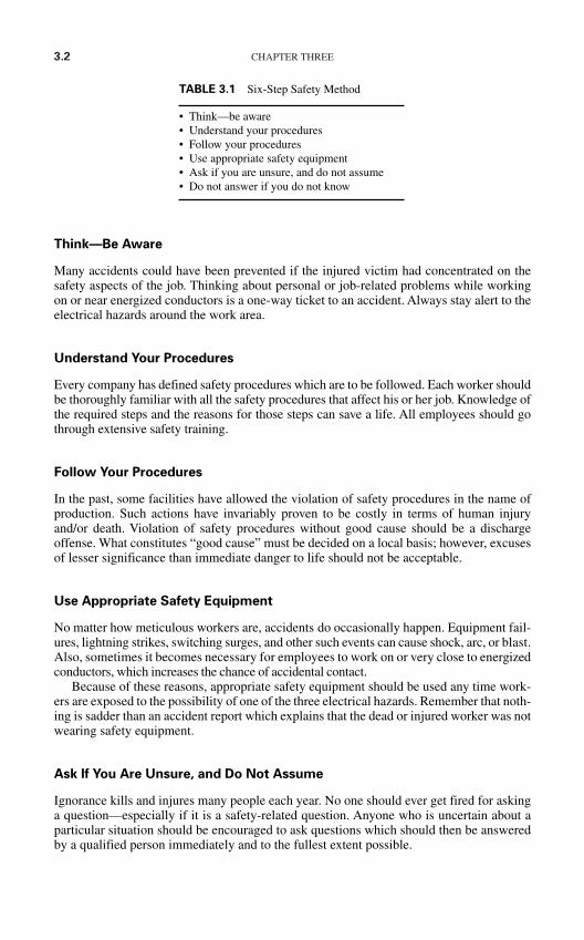
3.2 CHAPTER THREE
Think—Be Aware
Many accidents could have been prevented if the injured victim had concentrated on thesafety aspects of the job. Thinking about personal or job-related problems while workingon or near energized conductors is a one-way ticket to an accident. Always stay alert to theelectrical hazards around the work area.
Understand Your Procedures
Every company has defined safety procedures which are to be followed. Each worker shouldbe thoroughly familiar with all the safety procedures that affect his or her job. Knowledge ofthe required steps and the reasons for those steps can save a life. All employees should gothrough extensive safety training.
Follow Your Procedures
In the past, some facilities have allowed the violation of safety procedures in the name ofproduction. Such actions have invariably proven to be costly in terms of human injuryand/or death. Violation of safety procedures without good cause should be a dischargeoffense. What constitutes “good cause” must be decided on a local basis; however, excusesof lesser significance than immediate danger to life should not be acceptable.
Use Appropriate Safety Equipment
No matter how meticulous workers are, accidents do occasionally happen. Equipment fail-ures, lightning strikes, switching surges, and other such events can cause shock, arc, or blast.Also, sometimes it becomes necessary for employees to work on or very close to energizedconductors, which increases the chance of accidental contact.
Because of these reasons, appropriate safety equipment should be used any time work-ers are exposed to the possibility of one of the three electrical hazards. Remember that noth-ing is sadder than an accident report which explains that the dead or injured worker was notwearing safety equipment.
Ask If You Are Unsure, and Do Not Assume
Ignorance kills and injures many people each year. No one should ever get fired for askinga question—especially if it is a safety-related question. Anyone who is uncertain about aparticular situation should be encouraged to ask questions which should then be answeredby a qualified person immediately and to the fullest extent possible.
• Think—be aware• Understand your procedures• Follow your procedures• Use appropriate safety equipment• Ask if you are unsure, and do not assume• Do not answer if you do not know
TABLE 3.1 Six-Step Safety Method
Do Not Answer If You Do Not Know
No one should answer a question if they are not certain of the answer. Self-proclaimedexperts should keep their opinions to themselves.
PRE-JOB BRIEFINGS
Definition
A pre-job briefing (sometimes called a “tailgate meeting”) is a meeting which informs allworkers of the job requirements. In particular a pre-job briefing is used to alert workers topotential safety hazards. A pre-job briefing need not be a formal gathering; however, it ismandatory that all workers involved attend, and worker attendance should be documented.
What Should Be Included?
OSHA rules require that a pre-job briefing discuss, at a minimum, the following issues:
Special precautions to be taken Hazards associated with the job Energy control procedures Procedures and Policies Personal Protective Equipment
Note that the first letters of each of these bulleted items form the acronym SHEPP, whichcan be used to help remember the important issues that need to be discussed.
Pre-job briefings should be proactive meetings in which workers are informally quizzedto make certain that they fully understand the safety issues that they will face.
When Should Pre-Job Briefings Be Held?
At the beginning of each shift At the beginning of any new job Any time that job conditions change When new personnel are introduced to an ongoing job
ENERGIZED OR DE-ENERGIZED?
The Fundamental Rules
All regulatory standards are quite clear in their requirements to de-energize a circuit beforeemployees work on or near it. Stated simply:
All circuits and components to which employees may be exposed should be de-energized before work begins.
SAFETY PROCEDURES AND METHODS 3.3
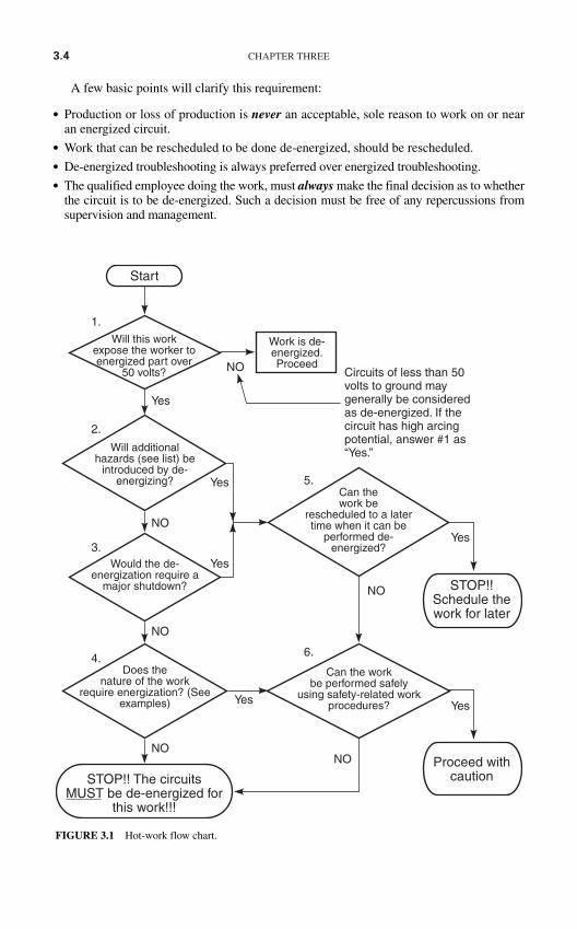
3.4 CHAPTER THREE
Start
1.
2.
3.
Yes
Yes
Yes
Yes
NO
NO
NO
NO
Will this workexpose the worker toenergized part over
50 volts?
Work is de-energized.Proceed
Circuits of less than 50volts to ground maygenerally be consideredas de-energized. If thecircuit has high arcingpotential, answer #1 as“Yes.”Will additional
hazards (see list) beintroduced by de-
energizing?
Would the de-energization require a
major shutdown?
Does thenature of the work
require energization? (Seeexamples)
STOP!! The circuitsMUST be de-energized for
this work!!!
NONO
4.
5.
Yes
Can thework be
rescheduled to a latertime when it can be
performed de-energized?
Can the workbe performed safely
using safety-related workprocedures?
6.
STOP!!Schedule thework for later
Yes
Proceed withcaution
FIGURE 3.1 Hot-work flow chart.
A few basic points will clarify this requirement:
Production or loss of production is never an acceptable, sole reason to work on or nearan energized circuit.
Work that can be rescheduled to be done de-energized, should be rescheduled. De-energized troubleshooting is always preferred over energized troubleshooting. The qualified employee doing the work, must always make the final decision as to whether
the circuit is to be de-energized. Such a decision must be free of any repercussions fromsupervision and management.
SAFETY PROCEDURES AND METHODS 3.5
A Hot-Work Decision Tree
Figure 3.1 illustrates a method that may be used to determine the need to work on a circuitwhen it is energized. The numbers in the following explanation refer to the numbersassigned to each of the decision blocks shown in Fig. 3.1.
1. Work performed on or near circuits of less than 50 V to ground may usually be consid-ered to be de-energized work. Note that if the circuit has high arcing capability, decision1 should be answered as a “Yes.”
2. If de-energizing simply changes the hazard from one type to another, or if it actuallyincreases the degree of hazard. This decision should be answered “Yes.” Table 3.2lists the types of additional hazards that should be considered in answering thisdecision.
3. The need to keep production up is common to all industries—manufacturing, petrochem-ical, mining, steel, aluminum, and electrical power systems. However, many employersabuse the concept that “production must continue.” The following points should clarifywhen production issues may be allowed to influence the decision to de-energize.a. Shutdown of a continuous process that will add extraordinary collateral costs may be
a signal to work on the circuit energized. Table 3.3 lists examples of these types ofcollateral costs.
b. Shutdown of a simple system which does not introduce the types of problems identi-fied in Table 3.3 should always be undertaken rather than allowing energized work.
4. In some cases, the very nature of the work or the equipment requires that the circuit remainenergized. Table 3.4 shows three of the most common examples of such work. Note, how-ever that this work should still be de-energized if it is possible to do it that way. For exam-ple, troubleshooting a motor starter may be faster with the circuit energized; however, if itcan be done de-energized it should be, even at the cost of a little more time.
5. If decisions 2 or 3 lead in the direction of energized work, the next decision should berescheduling. If energized work can be done de-energized on a different shift or at a latertime, it should be postponed. Many companies miss this elegantly simple alternative toexposing their personnel to hazardous electrical energy.
6. The final, and arguably the most important, decision of all is to determine whether thework can be done safely. If, in the opinion of the qualified personnel assessing the job, thework is simply too dangerous to do with the circuits energized, then it must be de-energized.
TABLE 3.2 Examples of Additional Hazards
• Interruption of life-support systems• Deactivation of emergency alarms• Shutdown of ventilation to hazardous locations• Removal of illumination from the work area
TABLE 3.3 Examples of Collateral Costs that May Justify Energized Work
• Excessive restart times in continuous process systems• High product loss costs (in polyethylene process, for example, the product has to be
physically dug out of process equipment after an unscheduled outage)
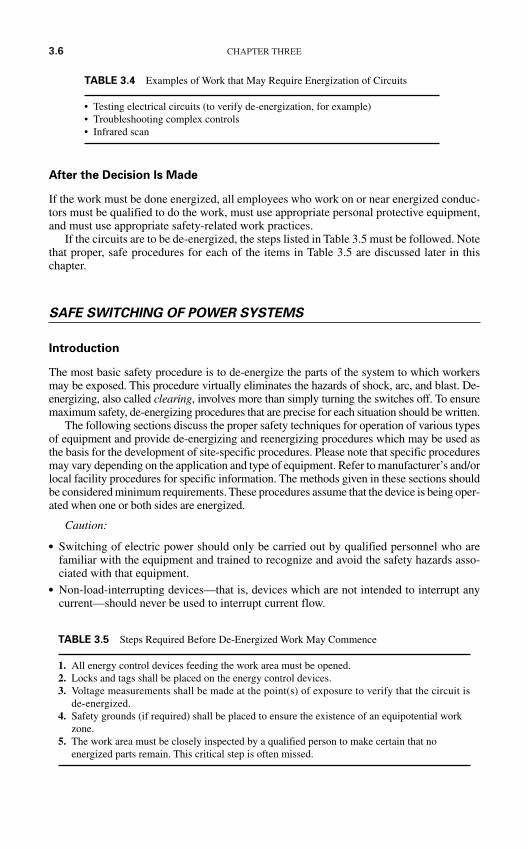
3.6 CHAPTER THREE
After the Decision Is Made
If the work must be done energized, all employees who work on or near energized conduc-tors must be qualified to do the work, must use appropriate personal protective equipment,and must use appropriate safety-related work practices.
If the circuits are to be de-energized, the steps listed in Table 3.5 must be followed. Notethat proper, safe procedures for each of the items in Table 3.5 are discussed later in thischapter.
SAFE SWITCHING OF POWER SYSTEMS
Introduction
The most basic safety procedure is to de-energize the parts of the system to which workersmay be exposed. This procedure virtually eliminates the hazards of shock, arc, and blast. De-energizing, also called clearing, involves more than simply turning the switches off. To ensuremaximum safety, de-energizing procedures that are precise for each situation should be written.
The following sections discuss the proper safety techniques for operation of various typesof equipment and provide de-energizing and reenergizing procedures which may be used asthe basis for the development of site-specific procedures. Please note that specific proceduresmay vary depending on the application and type of equipment. Refer to manufacturer’s and/orlocal facility procedures for specific information. The methods given in these sections shouldbe considered minimum requirements. These procedures assume that the device is being oper-ated when one or both sides are energized.
Caution:
Switching of electric power should only be carried out by qualified personnel who arefamiliar with the equipment and trained to recognize and avoid the safety hazards asso-ciated with that equipment.
Non-load-interrupting devices—that is, devices which are not intended to interrupt anycurrent—should never be used to interrupt current flow.
TABLE 3.4 Examples of Work that May Require Energization of Circuits
• Testing electrical circuits (to verify de-energization, for example)• Troubleshooting complex controls • Infrared scan
TABLE 3.5 Steps Required Before De-Energized Work May Commence
1. All energy control devices feeding the work area must be opened.2. Locks and tags shall be placed on the energy control devices.3. Voltage measurements shall be made at the point(s) of exposure to verify that the circuit is
de-energized.4. Safety grounds (if required) shall be placed to ensure the existence of an equipotential work
zone.5. The work area must be closely inspected by a qualified person to make certain that no
energized parts remain. This critical step is often missed.
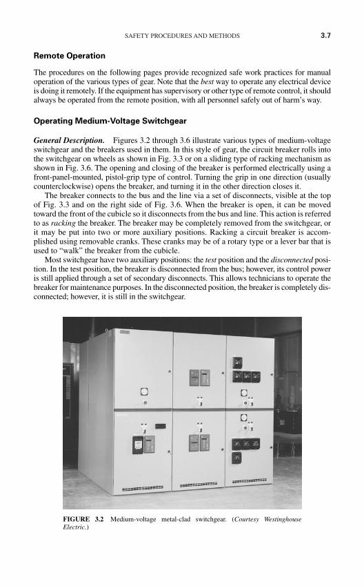
SAFETY PROCEDURES AND METHODS 3.7
Remote Operation
The procedures on the following pages provide recognized safe work practices for manualoperation of the various types of gear. Note that the best way to operate any electrical deviceis doing it remotely. If the equipment has supervisory or other type of remote control, it shouldalways be operated from the remote position, with all personnel safely out of harm’s way.
Operating Medium-Voltage Switchgear
General Description. Figures 3.2 through 3.6 illustrate various types of medium-voltageswitchgear and the breakers used in them. In this style of gear, the circuit breaker rolls intothe switchgear on wheels as shown in Fig. 3.3 or on a sliding type of racking mechanism asshown in Fig. 3.6. The opening and closing of the breaker is performed electrically using afront-panel-mounted, pistol-grip type of control. Turning the grip in one direction (usuallycounterclockwise) opens the breaker, and turning it in the other direction closes it.
The breaker connects to the bus and the line via a set of disconnects, visible at the topof Fig. 3.3 and on the right side of Fig. 3.6. When the breaker is open, it can be movedtoward the front of the cubicle so it disconnects from the bus and line. This action is referredto as racking the breaker. The breaker may be completely removed from the switchgear, orit may be put into two or more auxiliary positions. Racking a circuit breaker is accom-plished using removable cranks. These cranks may be of a rotary type or a lever bar that isused to “walk” the breaker from the cubicle.
Most switchgear have two auxiliary positions: the test position and the disconnected posi-tion. In the test position, the breaker is disconnected from the bus; however, its control poweris still applied through a set of secondary disconnects. This allows technicians to operate thebreaker for maintenance purposes. In the disconnected position, the breaker is completely dis-connected; however, it is still in the switchgear.
FIGURE 3.2 Medium-voltage metal-clad switchgear. (Courtesy WestinghouseElectric.)
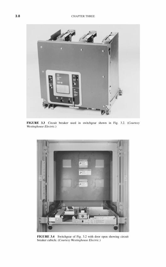
3.8 CHAPTER THREE
FIGURE 3.3 Circuit breaker used in switchgear shown in Fig. 3.2. (CourtesyWestinghouse Electric.)
FIGURE 3.4 Switchgear of Fig. 3.2 with door open showing circuitbreaker cubicle. (Courtesy Westinghouse Electric.)
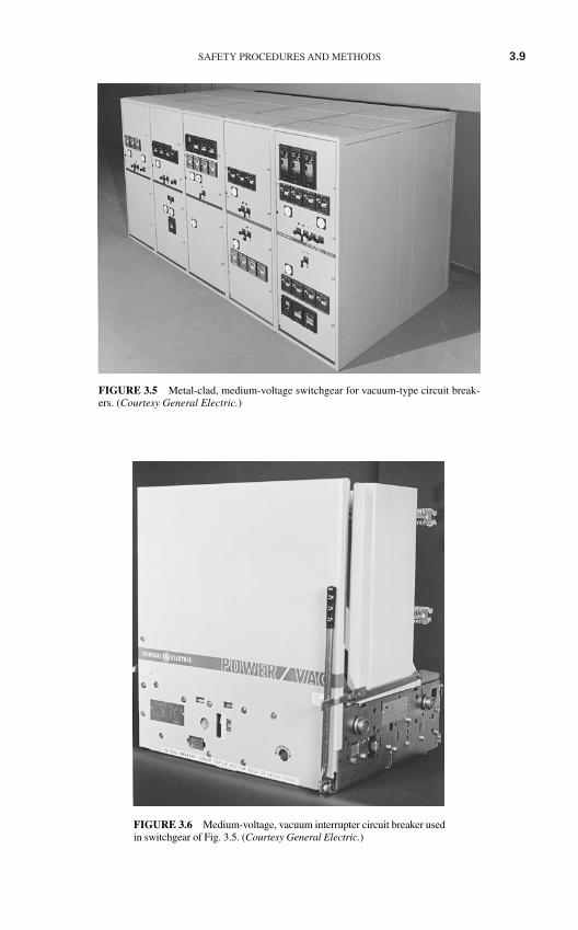
SAFETY PROCEDURES AND METHODS 3.9
FIGURE 3.5 Metal-clad, medium-voltage switchgear for vacuum-type circuit break-ers. (Courtesy General Electric.)
FIGURE 3.6 Medium-voltage, vacuum interrupter circuit breaker usedin switchgear of Fig. 3.5. (Courtesy General Electric.)
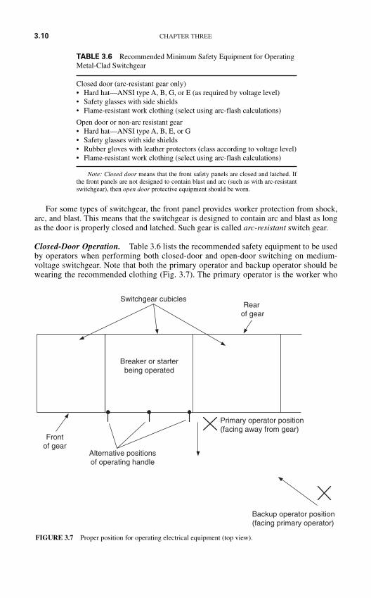
3.10 CHAPTER THREE
For some types of switchgear, the front panel provides worker protection from shock,arc, and blast. This means that the switchgear is designed to contain arc and blast as longas the door is properly closed and latched. Such gear is called arc-resistant switch gear.
Closed-Door Operation. Table 3.6 lists the recommended safety equipment to be usedby operators when performing both closed-door and open-door switching on medium-voltage switchgear. Note that both the primary operator and backup operator should bewearing the recommended clothing (Fig. 3.7). The primary operator is the worker who
Switchgear cubicles
Breaker or starterbeing operated
Alternative positionsof operating handle
Primary operator position(facing away from gear)
Backup operator position(facing primary operator)
Frontof gear
Rearof gear
FIGURE 3.7 Proper position for operating electrical equipment (top view).
TABLE 3.6 Recommended Minimum Safety Equipment for OperatingMetal-Clad Switchgear
Closed door (arc-resistant gear only)• Hard hat—ANSI type A, B, G, or E (as required by voltage level)• Safety glasses with side shields• Flame-resistant work clothing (select using arc-flash calculations)
Open door or non-arc resistant gear• Hard hat—ANSI type A, B, E, or G• Safety glasses with side shields• Rubber gloves with leather protectors (class according to voltage level)• Flame-resistant work clothing (select using arc-flash calculations)
Note: Closed door means that the front safety panels are closed and latched. Ifthe front panels are not designed to contain blast and arc (such as with arc-resistantswitchgear), then open door protective equipment should be worn.
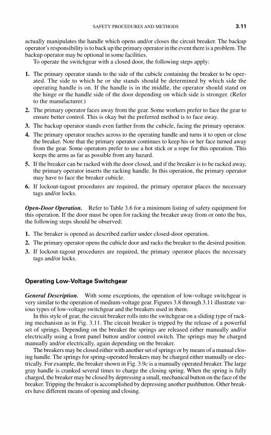
actually manipulates the handle which opens and/or closes the circuit breaker. The backupoperator’s responsibility is to back up the primary operator in the event there is a problem. Thebackup operator may be optional in some facilities.
To operate the switchgear with a closed door, the following steps apply:
1. The primary operator stands to the side of the cubicle containing the breaker to be oper-ated. The side to which he or she stands should be determined by which side theoperating handle is on. If the handle is in the middle, the operator should stand onthe hinge or the handle side of the door depending on which side is stronger. (Referto the manufacturer.)
2. The primary operator faces away from the gear. Some workers prefer to face the gear toensure better control. This is okay but the preferred method is to face away.
3. The backup operator stands even farther from the cubicle, facing the primary operator.
4. The primary operator reaches across to the operating handle and turns it to open or closethe breaker. Note that the primary operator continues to keep his or her face turned awayfrom the gear. Some operators prefer to use a hot stick or a rope for this operation. Thiskeeps the arms as far as possible from any hazard.
5. If the breaker can be racked with the door closed, and if the breaker is to be racked away,the primary operator inserts the racking handle. In this operation, the primary operatormay have to face the breaker cubicle.
6. If lockout-tagout procedures are required, the primary operator places the necessarytags and/or locks.
Open-Door Operation. Refer to Table 3.6 for a minimum listing of safety equipment forthis operation. If the door must be open for racking the breaker away from or onto the bus,the following steps should be observed:
1. The breaker is opened as described earlier under closed-door operation.
2. The primary operator opens the cubicle door and racks the breaker to the desired position.
3. If lockout-tagout procedures are required, the primary operator places the necessarytags and/or locks.
Operating Low-Voltage Switchgear
General Description. With some exceptions, the operation of low-voltage switchgear isvery similar to the operation of medium-voltage gear. Figures 3.8 through 3.11 illustrate var-ious types of low-voltage switchgear and the breakers used in them.
In this style of gear, the circuit breaker rolls into the switchgear on a sliding type of rack-ing mechanism as in Fig. 3.11. The circuit breaker is tripped by the release of a powerfulset of springs. Depending on the breaker the springs are released either manually and/orelectrically using a front panel button and/or control switch. The springs may be chargedmanually and/or electrically, again depending on the breaker.
The breakers may be closed either with another set of springs or by means of a manual clos-ing handle. The springs for spring-operated breakers may be charged either manually or elec-trically. For example, the breaker shown in Fig. 3.9c is a manually operated breaker. The largegray handle is cranked several times to charge the closing spring. When the spring is fullycharged, the breaker may be closed by depressing a small, mechanical button on the face of thebreaker. Tripping the breaker is accomplished by depressing another pushbutton. Other break-ers have different means of opening and closing.
SAFETY PROCEDURES AND METHODS 3.11
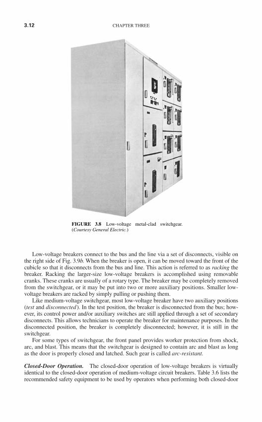
3.12 CHAPTER THREE
Low-voltage breakers connect to the bus and the line via a set of disconnects, visible onthe right side of Fig. 3.9b. When the breaker is open, it can be moved toward the front of thecubicle so that it disconnects from the bus and line. This action is referred to as racking thebreaker. Racking the larger-size low-voltage breakers is accomplished using removablecranks. These cranks are usually of a rotary type. The breaker may be completely removedfrom the switchgear, or it may be put into two or more auxiliary positions. Smaller low-voltage breakers are racked by simply pulling or pushing them.
Like medium-voltage switchgear, most low-voltage breaker have two auxiliary positions(test and disconnected). In the test position, the breaker is disconnected from the bus; how-ever, its control power and/or auxiliary switches are still applied through a set of secondarydisconnects. This allows technicians to operate the breaker for maintenance purposes. In thedisconnected position, the breaker is completely disconnected; however, it is still in theswitchgear.
For some types of switchgear, the front panel provides worker protection from shock,arc, and blast. This means that the switchgear is designed to contain arc and blast as longas the door is properly closed and latched. Such gear is called arc-resistant.
Closed-Door Operation. The closed-door operation of low-voltage breakers is virtuallyidentical to the closed-door operation of medium-voltage circuit breakers. Table 3.6 lists therecommended safety equipment to be used by operators when performing both closed-door
FIGURE 3.8 Low-voltage metal-clad switchgear.(Courtesy General Electric.)
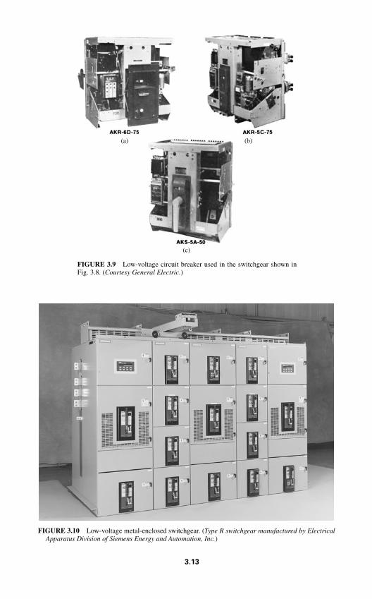
FIGURE 3.9 Low-voltage circuit breaker used in the switchgear shown inFig. 3.8. (Courtesy General Electric.)
(a) (b)
(c)
FIGURE 3.10 Low-voltage metal-enclosed switchgear. (Type R switchgear manufactured by ElectricalApparatus Division of Siemens Energy and Automation, Inc.)
3.13
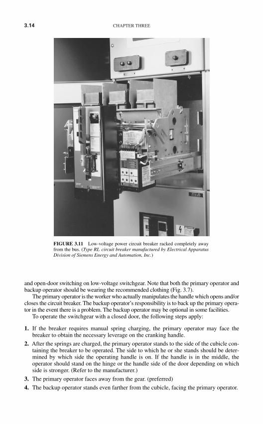
3.14 CHAPTER THREE
FIGURE 3.11 Low-voltage power circuit breaker racked completely awayfrom the bus. (Type RL circuit breaker manufactured by Electrical ApparatusDivision of Siemens Energy and Automation, Inc.)
and open-door switching on low-voltage switchgear. Note that both the primary operator andbackup operator should be wearing the recommended clothing (Fig. 3.7).
The primary operator is the worker who actually manipulates the handle which opens and/orcloses the circuit breaker. The backup operator’s responsibility is to back up the primary opera-tor in the event there is a problem. The backup operator may be optional in some facilities.
To operate the switchgear with a closed door, the following steps apply:
1. If the breaker requires manual spring charging, the primary operator may face thebreaker to obtain the necessary leverage on the cranking handle.
2. After the springs are charged, the primary operator stands to the side of the cubicle con-taining the breaker to be operated. The side to which he or she stands should be deter-mined by which side the operating handle is on. If the handle is in the middle, theoperator should stand on the hinge or the handle side of the door depending on whichside is stronger. (Refer to the manufacturer.)
3. The primary operator faces away from the gear. (preferred)
4. The backup operator stands even farther from the cubicle, facing the primary operator.
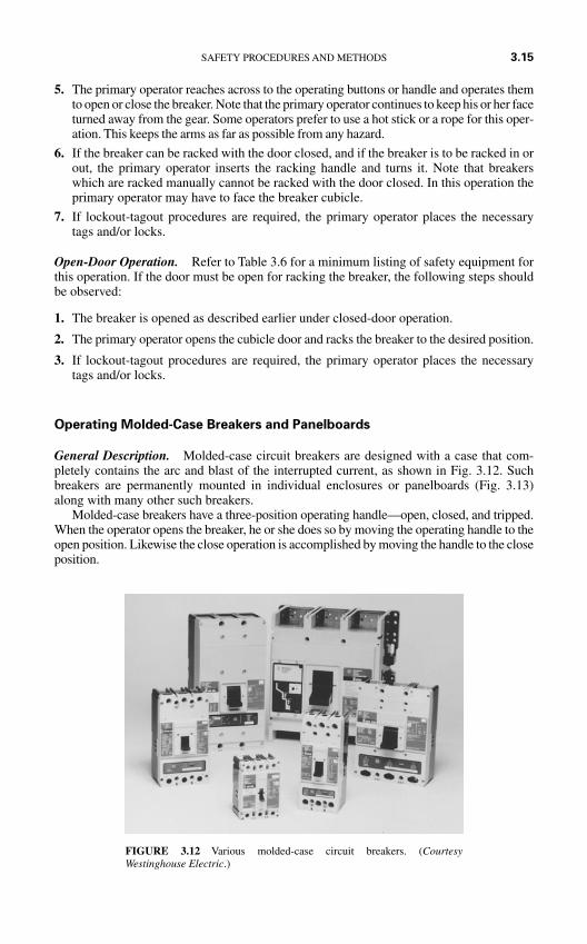
5. The primary operator reaches across to the operating buttons or handle and operates themto open or close the breaker. Note that the primary operator continues to keep his or her faceturned away from the gear. Some operators prefer to use a hot stick or a rope for this oper-ation. This keeps the arms as far as possible from any hazard.
6. If the breaker can be racked with the door closed, and if the breaker is to be racked in orout, the primary operator inserts the racking handle and turns it. Note that breakerswhich are racked manually cannot be racked with the door closed. In this operation theprimary operator may have to face the breaker cubicle.
7. If lockout-tagout procedures are required, the primary operator places the necessarytags and/or locks.
Open-Door Operation. Refer to Table 3.6 for a minimum listing of safety equipment forthis operation. If the door must be open for racking the breaker, the following steps shouldbe observed:
1. The breaker is opened as described earlier under closed-door operation.
2. The primary operator opens the cubicle door and racks the breaker to the desired position.
3. If lockout-tagout procedures are required, the primary operator places the necessarytags and/or locks.
Operating Molded-Case Breakers and Panelboards
General Description. Molded-case circuit breakers are designed with a case that com-pletely contains the arc and blast of the interrupted current, as shown in Fig. 3.12. Suchbreakers are permanently mounted in individual enclosures or panelboards (Fig. 3.13)along with many other such breakers.
Molded-case breakers have a three-position operating handle—open, closed, and tripped.When the operator opens the breaker, he or she does so by moving the operating handle to theopen position. Likewise the close operation is accomplished by moving the handle to the closeposition.
SAFETY PROCEDURES AND METHODS 3.15
FIGURE 3.12 Various molded-case circuit breakers. (CourtesyWestinghouse Electric.)
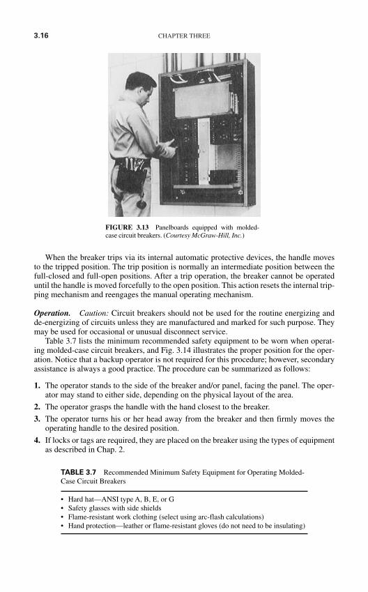
3.16 CHAPTER THREE
When the breaker trips via its internal automatic protective devices, the handle movesto the tripped position. The trip position is normally an intermediate position between thefull-closed and full-open positions. After a trip operation, the breaker cannot be operateduntil the handle is moved forcefully to the open position. This action resets the internal trip-ping mechanism and reengages the manual operating mechanism.
Operation. Caution: Circuit breakers should not be used for the routine energizing andde-energizing of circuits unless they are manufactured and marked for such purpose. Theymay be used for occasional or unusual disconnect service.
Table 3.7 lists the minimum recommended safety equipment to be worn when operat-ing molded-case circuit breakers, and Fig. 3.14 illustrates the proper position for the oper-ation. Notice that a backup operator is not required for this procedure; however, secondaryassistance is always a good practice. The procedure can be summarized as follows:
1. The operator stands to the side of the breaker and/or panel, facing the panel. The oper-ator may stand to either side, depending on the physical layout of the area.
2. The operator grasps the handle with the hand closest to the breaker.
3. The operator turns his or her head away from the breaker and then firmly moves theoperating handle to the desired position.
4. If locks or tags are required, they are placed on the breaker using the types of equipmentas described in Chap. 2.
FIGURE 3.13 Panelboards equipped with molded-case circuit breakers. (Courtesy McGraw-Hill, Inc.)
TABLE 3.7 Recommended Minimum Safety Equipment for Operating Molded-Case Circuit Breakers
• Hard hat—ANSI type A, B, E, or G • Safety glasses with side shields• Flame-resistant work clothing (select using arc-flash calculations)• Hand protection—leather or flame-resistant gloves (do not need to be insulating)
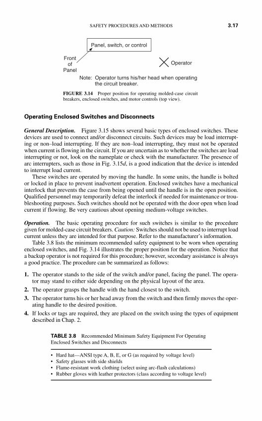
Operating Enclosed Switches and Disconnects
General Description. Figure 3.15 shows several basic types of enclosed switches. Thesedevices are used to connect and/or disconnect circuits. Such devices may be load interrupt-ing or non–load interrupting. If they are non–load interrupting, they must not be operatedwhen current is flowing in the circuit. If you are uncertain as to whether the switches are loadinterrupting or not, look on the nameplate or check with the manufacturer. The presence ofarc interrupters, such as those in Fig. 3.15d, is a good indication that the device is intendedto interrupt load current.
These switches are operated by moving the handle. In some units, the handle is boltedor locked in place to prevent inadvertent operation. Enclosed switches have a mechanicalinterlock that prevents the case from being opened until the handle is in the open position.Qualified personnel may temporarily defeat the interlock if needed for maintenance or trou-bleshooting purposes. Such switches should not be operated with the door open when loadcurrent if flowing. Be very cautious about opening medium-voltage switches.
Operation. The basic operating procedure for such switches is similar to the proceduregiven for molded-case circuit breakers. Caution: Switches should not be used to interrupt loadcurrent unless they are intended for that purpose. Refer to the manufacturer’s information.
Table 3.8 lists the minimum recommended safety equipment to be worn when operatingenclosed switches, and Fig. 3.14 illustrates the proper position for the operation. Notice thata backup operator is not required for this procedure; however, secondary assistance is alwaysa good practice. The procedure can be summarized as follows:
1. The operator stands to the side of the switch and/or panel, facing the panel. The opera-tor may stand to either side depending on the physical layout of the area.
2. The operator grasps the handle with the hand closest to the switch.
3. The operator turns his or her head away from the switch and then firmly moves the oper-ating handle to the desired position.
4. If locks or tags are required, they are placed on the switch using the types of equipmentdescribed in Chap. 2.
SAFETY PROCEDURES AND METHODS 3.17
FIGURE 3.14 Proper position for operating molded-case circuitbreakers, enclosed switches, and motor controls (top view).
Panel, switch, or control
Operator
Note: Operator turns his/her head when operating the circuit breaker.
Frontof
Panel
TABLE 3.8 Recommended Minimum Safety Equipment For OperatingEnclosed Switches and Disconnects
• Hard hat—ANSI type A, B, E, or G (as required by voltage level)• Safety glasses with side shields• Flame-resistant work clothing (select using arc-flash calculations)• Rubber gloves with leather protectors (class according to voltage level)
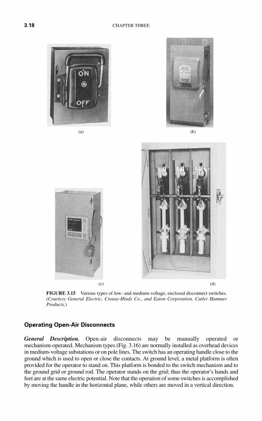
Operating Open-Air Disconnects
General Description. Open-air disconnects may be manually operated ormechanism-operated. Mechanism types (Fig. 3.16) are normally installed as overhead devicesin medium-voltage substations or on pole lines. The switch has an operating handle close to theground which is used to open or close the contacts. At ground level, a metal platform is oftenprovided for the operator to stand on. This platform is bonded to the switch mechanism and tothe ground grid or ground rod. The operator stands on the grid; thus the operator’s hands andfeet are at the same electric potential. Note that the operation of some switches is accomplishedby moving the handle in the horizontal plane, while others are moved in a vertical direction.
3.18 CHAPTER THREE
(c) (d)
FIGURE 3.15 Various types of low- and medium-voltage, enclosed disconnect switches.(Courtesy General Electric, Crouse-Hinds Co., and Eaton Corporation, Cutler HammerProducts.)
(a) (b)
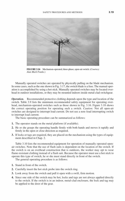
SAFETY PROCEDURES AND METHODS 3.19
Manually operated switches are operated by physically pulling on the blade mechanism.In some cases, such as the one shown in Fig. 3.17, the switch blade is a fuse. The manual oper-ation is accomplished by using a hot stick. Manually operated switches may be located over-head in outdoor installations, or they may be mounted indoors inside metal-clad switchgear.
Operation. Recommended protective clothing depends upon the type and location of theswitch. Table 3.9 lists the minimum recommended safety equipment for operating over-head, mechanism-operated switches such as those shown in Fig. 3.16. Figure 3.18 showsthe correct operating position for operating such a switch. Caution: Not all open-airswitches are designed to interrupt load current. Do not use a non–load interrupting switchto interrupt load current.
The basic operating procedure can be summarized as follows:
1. The operator stands on the metal platform (if available).
2. He or she grasps the operating handle firmly with both hands and moves it rapidly andfirmly in the open or close direction as required.
3. If locks or tags are required, they are placed on the mechanism using the types of equip-ment described in Chap. 2.
Table 3.10 lists the recommended equipment for operation of manually operated open-air switches. Note that the use of flash suits is dependent on the location of the switch. Ifthe switch is on an overhead construction that is outdoors, the worker may opt to wearflame-resistant clothing instead of a flash suit. Because the operator must use a hot stick tooperate this type of switch, he or she must stand directly in front of the switch.
The general operating procedure is as follows:
1. Stand in front of the switch.
2. Carefully insert the hot stick probe into the switch ring.
3. Look away from the switch and pull it open with a swift, firm motion.
4. Since one side of the switch may be hot, locks and tags are not always applied directlyto the switch. If the switch is in an indoor, metal-clad enclosure, the lock and tag maybe applied to the door of the gear.
FIGURE 3.16 Mechanism-operated, three-phase, open-air switch. (CourtesyAlan Mark Franks.)
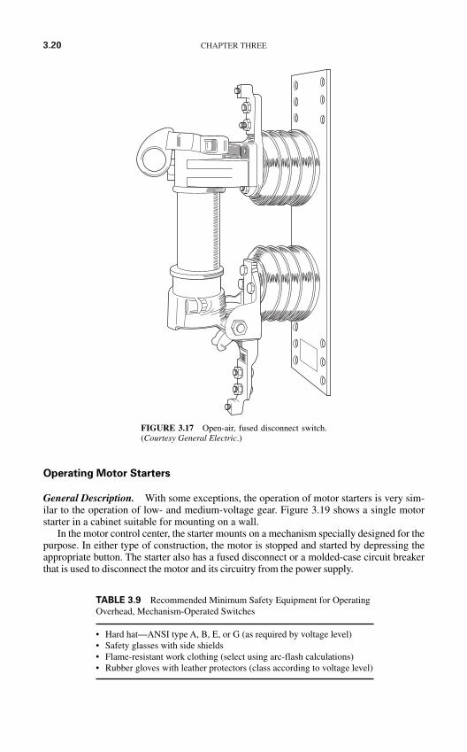
3.20 CHAPTER THREE
Operating Motor Starters
General Description. With some exceptions, the operation of motor starters is very sim-ilar to the operation of low- and medium-voltage gear. Figure 3.19 shows a single motorstarter in a cabinet suitable for mounting on a wall.
In the motor control center, the starter mounts on a mechanism specially designed for thepurpose. In either type of construction, the motor is stopped and started by depressing theappropriate button. The starter also has a fused disconnect or a molded-case circuit breakerthat is used to disconnect the motor and its circuitry from the power supply.
TABLE 3.9 Recommended Minimum Safety Equipment for OperatingOverhead, Mechanism-Operated Switches
• Hard hat—ANSI type A, B, E, or G (as required by voltage level)• Safety glasses with side shields• Flame-resistant work clothing (select using arc-flash calculations)• Rubber gloves with leather protectors (class according to voltage level)
FIGURE 3.17 Open-air, fused disconnect switch.(Courtesy General Electric.)
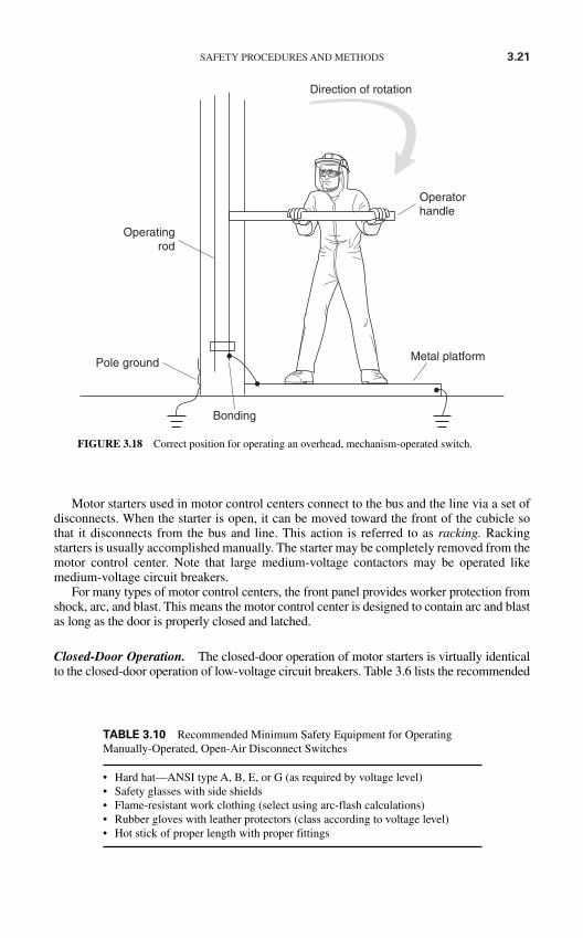
SAFETY PROCEDURES AND METHODS 3.21
Bonding
Operatingrod
Operatorhandle
Direction of rotation
Metal platformPole ground
FIGURE 3.18 Correct position for operating an overhead, mechanism-operated switch.
Motor starters used in motor control centers connect to the bus and the line via a set ofdisconnects. When the starter is open, it can be moved toward the front of the cubicle sothat it disconnects from the bus and line. This action is referred to as racking. Rackingstarters is usually accomplished manually. The starter may be completely removed from themotor control center. Note that large medium-voltage contactors may be operated likemedium-voltage circuit breakers.
For many types of motor control centers, the front panel provides worker protection fromshock, arc, and blast. This means the motor control center is designed to contain arc and blastas long as the door is properly closed and latched.
Closed-Door Operation. The closed-door operation of motor starters is virtually identicalto the closed-door operation of low-voltage circuit breakers. Table 3.6 lists the recommended
TABLE 3.10 Recommended Minimum Safety Equipment for OperatingManually-Operated, Open-Air Disconnect Switches
• Hard hat—ANSI type A, B, E, or G (as required by voltage level)• Safety glasses with side shields• Flame-resistant work clothing (select using arc-flash calculations)• Rubber gloves with leather protectors (class according to voltage level)• Hot stick of proper length with proper fittings
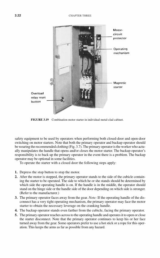
3.22 CHAPTER THREE
FIGURE 3.19 Combination motor starter in individual metal-clad cabinet.
safety equipment to be used by operators when performing both closed-door and open-doorswitching on motor starters. Note that both the primary operator and backup operator shouldbe wearing the recommended clothing (Fig. 3.7). The primary operator is the worker who actu-ally manipulates the handle that opens and/or closes the motor starter. The backup operator’sresponsibility is to back up the primary operator in the event there is a problem. The backupoperator may be optional in some facilities.
To operate the starter with a closed door the following steps apply:
1. Depress the stop button to stop the motor.2. After the motor is stopped, the primary operator stands to the side of the cubicle contain-
ing the starter to be operated. The side to which he or she stands should be determined bywhich side the operating handle is on. If the handle is in the middle, the operator shouldstand on the hinge side or the handle side of the door depending on which side is stronger.(Refer to the manufacturer.)
3. The primary operator faces away from the gear. Note: If the operating handle of the dis-connect has a very tight operating mechanism, the primary operator may face the motorstarter to obtain the necessary leverage on the cranking handle.
4. The backup operator stands even farther from the cubicle, facing the primary operator.5. The primary operator reaches across to the operating handle and operates it to open or close
the starter disconnect. Note that the primary operator continues to keep his or her faceturned away from the gear. Some operators prefer to use a hot stick or a rope for this oper-ation. This keeps the arms as far as possible from any hazard.
6. If the starter can be racked with the door closed (an unusual configuration), and if thestarter is to be racked in or out, the primary operator inserts the racking handle and turnsit. Note that starters which are racked manually cannot be racked with the door closed.In this operation, the primary operator may have to face the breaker cubicle.
7. If lockout-tagout procedures are required, the primary operator places the necessarytags and/or locks.
Open-Door Operation. Refer to Table 3.6 for a minimum listing of safety equipment forthis operation. If the door must be open for racking the starter, the following steps shouldbe observed:
1. The motor is stopped as described earlier under closed-door operation.
2. The primary operator opens the cubicle door and racks the starter to the desired position.
3. If lockout-tagout procedures are required, the primary operator places the necessarytags and/or locks.
ENERGY CONTROL PROGRAMS
An energy control program is a procedure for the proper control of hazardous energysources. It should include a listing of company-approved steps for the proper and safe ener-gizing and de-energizing of energy isolation devices as well as general company policystatements on policies with respect to preferred methods of operation. Energy control pro-grams fall into two categories—general and specific.
General Energy Control Programs
Overview. A general energy program is one that is inherently generic in nature. Its stepsare broad-based and designed in such a way that the program can be used as a procedure fora wide variety of equipment types. General energy control programs should be used onlywhen the equipment being isolated meets all the following criteria:
The equipment can be disabled, so it has no potential for the release of stored or residualenergy after shutdown.
The equipment is supplied from a single energy source which can be readily identifiedand isolated.
The equipment is completely de-energized and deactivated by the isolation and lock-ing out procedure.
No employees are allowed to work on or near the equipment until it has been tagged andlocked. (See the tagout-lockout section later in this chapter.)
A single lockout device will achieve a locked-out condition. The isolating circuit breakers or switches are under the exclusive control of the employee(s)
who placed the lock and tag. De-energizing and working on the equipment does not create a hazard for other employees. There have been no accidents involving unexpected activation or reenergization of the
equipment during previous servicing.
SAFETY PROCEDURES AND METHODS 3.23
Specific Energy Control Programs
When a part of the system or piece of equipment does not meet all the criteria laid out inthe overview to this section, a specific energy control program should be written. Althoughthe procedures will vary depending on the specifics of the installation, at a minimum theprogram should include the following information:
The description of the system and/or equipment that will be de-energized. Any controls, such as motor starter pushbuttons, that exist on the equipment. The voltages and short circuit capacities of the parts of the system which will be de-energized. The circuit breakers, switches, or contactors which are used to de-energize the system. The steps that must be used to de-energize the system. The steps should include:
1. The methods and order of operation of the circuit breakers, switches, and so on.2. Any special requirements for the lockout-tagout procedure.3. Special notifications and safety requirements.
Reenergizing requirements and procedures.
Basic Energy Control Rules
The safest and securest method to protect personnel from the electrical hazard is to de-energize the conductors which they must work on or near. De-energization is the preferredmethod.
If conductors cannot be de-energized, safety equipment and safety-related work prac-tices must be used to protect personnel exposed to the energized conductors.
Before personnel are allowed to work on or near any exposed, de-energized conductors,the circuit breakers and/or disconnect switches must be locked and tagged to prevent theirinadvertent operation.
All personnel should be instructed to never operate or attempt to operate any circuitbreaker and/or disconnect switch when it is tagged and/or locked.
Only authorized, qualified, and trained personnel should be allowed to operate electricequipment.
Locks and tags should be removed only by the personnel that placed them. Two excep-tions may apply under the following situations:
1. If the worker who placed the lock and tag is not available, his or her lock and tag maybe removed by a qualified person who is authorized to perform such an action. Thisprocedure is often called bypassing control as the person who removes the lock and tagis, in fact, bypassing the authority (control) of the person whose tag is being removed.
2. Some facilities may authorize the concept of a group lock. A group lock is placed by anauthorized shift worker, such as the shift operator, and may be removed by anotherauthorized shift worker. This activity should not be used to prevent any employee fromplacing his or her tag and lock on energy-isolating devices that may feed conductorswhich they must work on or near.
De-energizing Equipment. The general energy program for de-energizing equipmentshould include the following steps:
1. Before beginning the process, carefully identify the voltage levels and short circuitcapabilities of the portion of the system which will be de-energized. This informationserves to establish the level of the hazard to all personnel.
3.24 CHAPTER THREE
2. Notify all employees who will be affected by the de-energization that the system is tobe de-energized.
3. Perform necessary checks and inspections to ensure that de-energizing the equipmentwill not introduce additional safety hazards, for example, de-energizing safety-relatedventilation systems.
4. Shut down all processes being fed by the electric system which is to be de-energized.
5. Open the appropriate circuit breaker and/or switch.
6. Rack the circuit breaker away from the bus if it is of the type that can be manipulatedin this manner.
7. Release stored energy from springs, hydraulic systems, or pneumatics.
8. Discharge and ground any capacitors located in the de-energized portions of the system.
9. Apply tags and/or locks.
10. Attempt to operate the breaker and/or switch to make certain that the locks are pre-venting operation. If a motor starter is involved, press the start button to make certainthe motor will not start.
11. Measure the voltage on the conductors to which employees at the point where they willbe exposed.
12. Notify personnel that the system is safely de-energized, locked, and tagged.
Reenergizing Equipment. Reenergization of some systems is more hazardous than de-energization. While the equipment has been out of service, personnel have grown used to itsde-energized voltage status. In addition, tools and/or other equipment may have been inad-vertently left on or near exposed conductors.
Because of these factors, the same type of rigorous steps should be followed duringreenergization.
1. All personnel should be notified that the system is to be reenergized and warned to stayclear of circuits and equipment.
2. A trained, qualified person should conduct all tests and visual inspections necessary to ver-ify that all tools, electric jumpers, shorts, grounds, and other such devices have beenremoved and that the circuits are ready to be reenergized.
3. Close and secure all cabinet doors and other safety-related enclosures.
4. Because the tests and inspections may have required some time, the personnel warningsshould be repeated.
5. Locks and tags should be removed by the personnel that placed them.
6. If breakers were racked into disconnected positions, they should be racked in the con-nected position.
7. Make final checks and tests, and issue final warnings to all personnel.
8. Reenergize the system by closing and reconnecting breakers and switches. These opera-tions are normally carried out in the reverse order of how they were opened.
Procedures Involving More than One Person. When more than one person is required tolock and tag equipment, each person will place his or her own personal lock and tag on thecircuit breakers and/or switches. The placement of multiple locks and tags on equipment isoften called ganging. Since few circuit breakers or switches have the ability to accept mul-tiple locks and tags, this procedure can take one of two common approaches.
SAFETY PROCEDURES AND METHODS 3.25
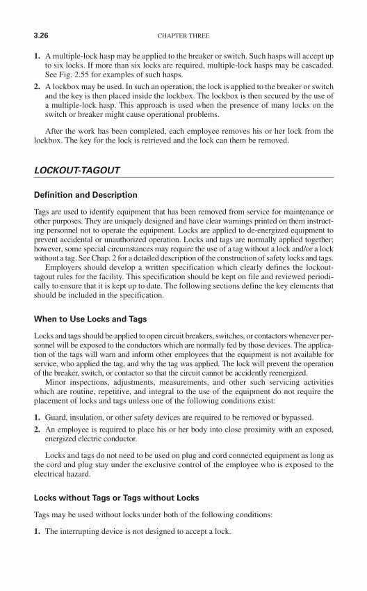
1. A multiple-lock hasp may be applied to the breaker or switch. Such hasps will accept upto six locks. If more than six locks are required, multiple-lock hasps may be cascaded.See Fig. 2.55 for examples of such hasps.
2. A lockbox may be used. In such an operation, the lock is applied to the breaker or switchand the key is then placed inside the lockbox. The lockbox is then secured by the use ofa multiple-lock hasp. This approach is used when the presence of many locks on theswitch or breaker might cause operational problems.
After the work has been completed, each employee removes his or her lock from thelockbox. The key for the lock is retrieved and the lock can them be removed.
LOCKOUT-TAGOUT
Definition and Description
Tags are used to identify equipment that has been removed from service for maintenance orother purposes. They are uniquely designed and have clear warnings printed on them instruct-ing personnel not to operate the equipment. Locks are applied to de-energized equipment toprevent accidental or unauthorized operation. Locks and tags are normally applied together;however, some special circumstances may require the use of a tag without a lock and/or a lockwithout a tag. See Chap. 2 for a detailed description of the construction of safety locks and tags.
Employers should develop a written specification which clearly defines the lockout-tagout rules for the facility. This specification should be kept on file and reviewed periodi-cally to ensure that it is kept up to date. The following sections define the key elements thatshould be included in the specification.
When to Use Locks and Tags
Locks and tags should be applied to open circuit breakers, switches, or contactors whenever per-sonnel will be exposed to the conductors which are normally fed by those devices. The applica-tion of the tags will warn and inform other employees that the equipment is not available forservice, who applied the tag, and why the tag was applied. The lock will prevent the operationof the breaker, switch, or contactor so that the circuit cannot be accidently reenergized.
Minor inspections, adjustments, measurements, and other such servicing activitieswhich are routine, repetitive, and integral to the use of the equipment do not require theplacement of locks and tags unless one of the following conditions exist:
1. Guard, insulation, or other safety devices are required to be removed or bypassed.
2. An employee is required to place his or her body into close proximity with an exposed,energized electric conductor.
Locks and tags do not need to be used on plug and cord connected equipment as long asthe cord and plug stay under the exclusive control of the employee who is exposed to theelectrical hazard.
Locks without Tags or Tags without Locks
Tags may be used without locks under both of the following conditions:
1. The interrupting device is not designed to accept a lock.
3.26 CHAPTER THREE
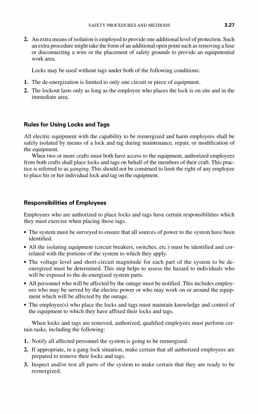
2. An extra means of isolation is employed to provide one additional level of protection. Suchan extra procedure might take the form of an additional open point such as removing a fuseor disconnecting a wire or the placement of safety grounds to provide an equipotentialwork area.
Locks may be used without tags under both of the following conditions:
1. The de-energization is limited to only one circuit or piece of equipment.
2. The lockout lasts only as long as the employee who places the lock is on site and in theimmediate area.
Rules for Using Locks and Tags
All electric equipment with the capability to be reenergized and harm employees shall besafely isolated by means of a lock and tag during maintenance, repair, or modification ofthe equipment.
When two or more crafts must both have access to the equipment, authorized employeesfrom both crafts shall place locks and tags on behalf of the members of their craft. This prac-tice is referred to as ganging. This should not be construed to limit the right of any employeeto place his or her individual lock and tag on the equipment.
Responsibilities of Employees
Employees who are authorized to place locks and tags have certain responsibilities whichthey must exercise when placing those tags.
The system must be surveyed to ensure that all sources of power to the system have beenidentified.
All the isolating equipment (circuit breakers, switches, etc.) must be identified and cor-related with the portions of the system to which they apply.
The voltage level and short-circuit magnitude for each part of the system to be de-energized must be determined. This step helps to assess the hazard to individuals whowill be exposed to the de-energized system parts.
All personnel who will be affected by the outage must be notified. This includes employ-ees who may be served by the electric power or who may work on or around the equip-ment which will be affected by the outage.
The employee(s) who place the locks and tags must maintain knowledge and control ofthe equipment to which they have affixed their locks and tags.
When locks and tags are removed, authorized, qualified employees must perform cer-tain tasks, including the following:
1. Notify all affected personnel the system is going to be reenergized.
2. If appropriate, in a gang lock situation, make certain that all authorized employees areprepared to remove their locks and tags.
3. Inspect and/or test all parts of the system to make certain that they are ready to bereenergized.
SAFETY PROCEDURES AND METHODS 3.27
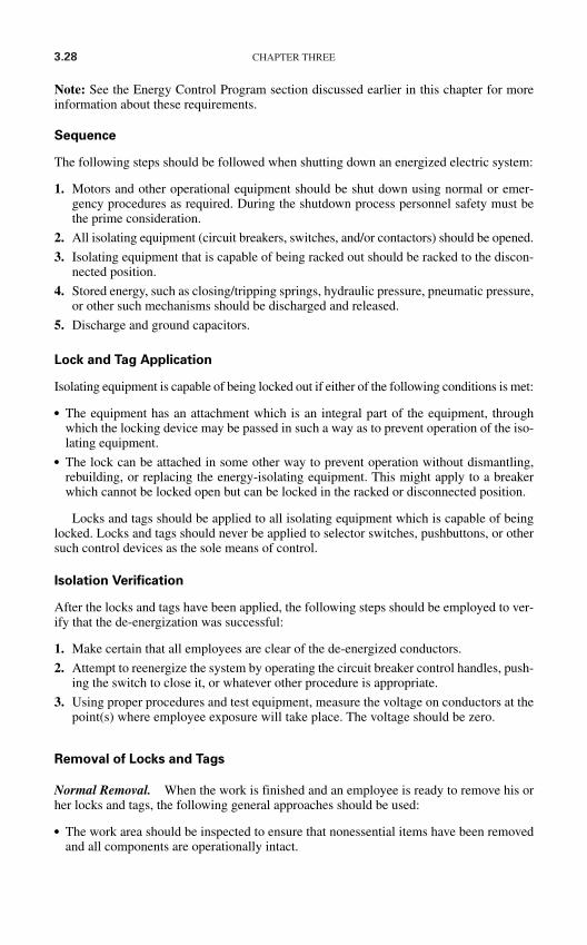
3.28 CHAPTER THREE
Note: See the Energy Control Program section discussed earlier in this chapter for moreinformation about these requirements.
Sequence
The following steps should be followed when shutting down an energized electric system:
1. Motors and other operational equipment should be shut down using normal or emer-gency procedures as required. During the shutdown process personnel safety must bethe prime consideration.
2. All isolating equipment (circuit breakers, switches, and/or contactors) should be opened.
3. Isolating equipment that is capable of being racked out should be racked to the discon-nected position.
4. Stored energy, such as closing/tripping springs, hydraulic pressure, pneumatic pressure,or other such mechanisms should be discharged and released.
5. Discharge and ground capacitors.
Lock and Tag Application
Isolating equipment is capable of being locked out if either of the following conditions is met:
The equipment has an attachment which is an integral part of the equipment, throughwhich the locking device may be passed in such a way as to prevent operation of the iso-lating equipment.
The lock can be attached in some other way to prevent operation without dismantling,rebuilding, or replacing the energy-isolating equipment. This might apply to a breakerwhich cannot be locked open but can be locked in the racked or disconnected position.
Locks and tags should be applied to all isolating equipment which is capable of beinglocked. Locks and tags should never be applied to selector switches, pushbuttons, or othersuch control devices as the sole means of control.
Isolation Verification
After the locks and tags have been applied, the following steps should be employed to ver-ify that the de-energization was successful:
1. Make certain that all employees are clear of the de-energized conductors.
2. Attempt to reenergize the system by operating the circuit breaker control handles, push-ing the switch to close it, or whatever other procedure is appropriate.
3. Using proper procedures and test equipment, measure the voltage on conductors at thepoint(s) where employee exposure will take place. The voltage should be zero.
Removal of Locks and Tags
Normal Removal. When the work is finished and an employee is ready to remove his orher locks and tags, the following general approaches should be used:
The work area should be inspected to ensure that nonessential items have been removedand all components are operationally intact.
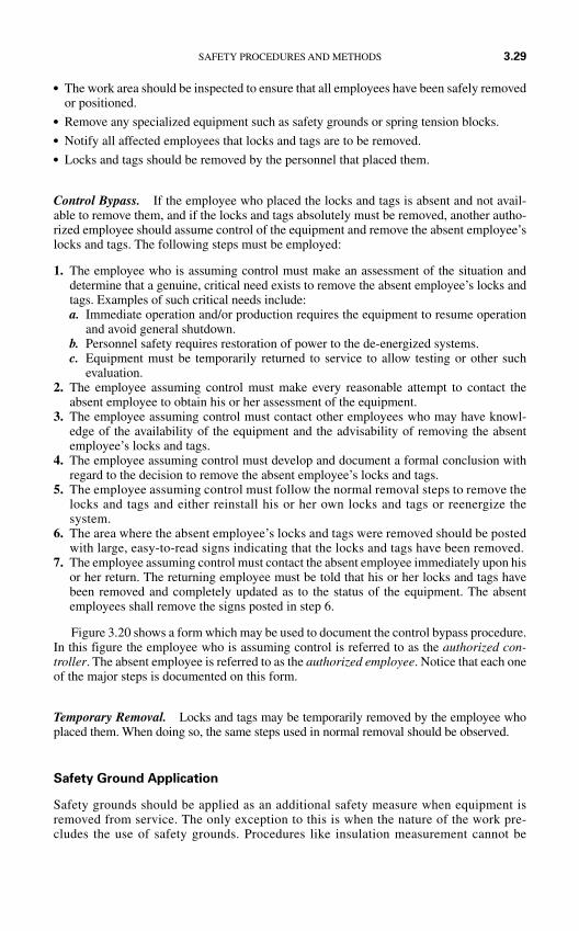
The work area should be inspected to ensure that all employees have been safely removedor positioned.
Remove any specialized equipment such as safety grounds or spring tension blocks. Notify all affected employees that locks and tags are to be removed. Locks and tags should be removed by the personnel that placed them.
Control Bypass. If the employee who placed the locks and tags is absent and not avail-able to remove them, and if the locks and tags absolutely must be removed, another autho-rized employee should assume control of the equipment and remove the absent employee’slocks and tags. The following steps must be employed:
1. The employee who is assuming control must make an assessment of the situation anddetermine that a genuine, critical need exists to remove the absent employee’s locks andtags. Examples of such critical needs include:a. Immediate operation and/or production requires the equipment to resume operation
and avoid general shutdown.b. Personnel safety requires restoration of power to the de-energized systems.c. Equipment must be temporarily returned to service to allow testing or other such
evaluation.2. The employee assuming control must make every reasonable attempt to contact the
absent employee to obtain his or her assessment of the equipment.3. The employee assuming control must contact other employees who may have knowl-
edge of the availability of the equipment and the advisability of removing the absentemployee’s locks and tags.
4. The employee assuming control must develop and document a formal conclusion withregard to the decision to remove the absent employee’s locks and tags.
5. The employee assuming control must follow the normal removal steps to remove thelocks and tags and either reinstall his or her own locks and tags or reenergize thesystem.
6. The area where the absent employee’s locks and tags were removed should be postedwith large, easy-to-read signs indicating that the locks and tags have been removed.
7. The employee assuming control must contact the absent employee immediately upon hisor her return. The returning employee must be told that his or her locks and tags havebeen removed and completely updated as to the status of the equipment. The absentemployees shall remove the signs posted in step 6.
Figure 3.20 shows a form which may be used to document the control bypass procedure.In this figure the employee who is assuming control is referred to as the authorized con-troller. The absent employee is referred to as the authorized employee. Notice that each oneof the major steps is documented on this form.
Temporary Removal. Locks and tags may be temporarily removed by the employee whoplaced them. When doing so, the same steps used in normal removal should be observed.
Safety Ground Application
Safety grounds should be applied as an additional safety measure when equipment isremoved from service. The only exception to this is when the nature of the work pre-cludes the use of safety grounds. Procedures like insulation measurement cannot be
SAFETY PROCEDURES AND METHODS 3.29

3.30 CHAPTER THREE
FIGURE 3.20 Lockout-tagout control bypass form.
SAFETY PROCEDURES AND METHODS 3.31
performed when safety grounds are applied; therefore, they may not be used, or must betemporarily disconnected for the measurement process.
Control Transfer
Lockout-tagout control may be transferred from one employee to another as long as bothemployees are present. The following steps should be used:
1. The employee relinquishing control follows all steps involved in the normal removal oflocks and tags.
2. The employee assuming control follows all steps involved in the normal application oflocks and tags.
Nonemployees and Contractors
Nonemployees such as contractors should be required to use a lockout-tagout programwhich provides the same or greater protection as that afforded by the facility’s procedure.Contractors should be required to submit their procedure for review and approval. No workshould be allowed until the contractor’s lockout-tagout program has been reviewed andapproved.
All employees should be familiarized with the contractor’s procedure and requiredto comply with it. Copies of the respective standards should be made available for bothcontractors and employees. Likewise all contractors must be familiar with the facility’sprocedure and must comply with it.
If the contractor is working on machines or equipment that have not yet been turned overto the facility, the contractor shall be required to lock and tag that equipment if it mightoperate and endanger employees. The contractor must guarantee the safety of the lockedand tagged installation. As an alternative to this procedure, the contractor should berequired to allow gang lockout and tagout with employees and contractor personnel.
Lockout-Tagout Training
All employees should be trained in the use, application, and removal of locks and tags. SeeChap. 13 for more information on general employee safety training.
FIGURE 3.20 (Continued)
3.32 CHAPTER THREE
Procedural Reviews
The entire lockout-tagout procedure should be reviewed at intervals no longer than 1 year.A review report should be issued which identifies the portions of the procedure which werereviewed, changes which were considered, and changes which were implemented.
VOLTAGE-MEASUREMENT TECHNIQUES
Purpose
No circuit should ever be presumed dead until it has been measured using reliable,prechecked test equipment. Good safety practice and current regulatory standards requirethat circuits be certified de-energized by measurement as the last definitive step in the lockout-tagout procedure.
Instrument Selection
Voltage-measuring instruments should be selected for the category, voltage level, the appli-cation location, short-circuit capacity, sensitivity requirements, and the circuit loadingrequirements of the circuit which is to be measured.
During voltage measurement, the instrument may be subjected to voltage transients.This is especially critical in low-voltage (below 1000 V) applications. When selecting alow-voltage-measuring instrument, be certain to select the correct category of instrumentas defined in IEC 61010. See Chap. 2 for a description of the categories.
Voltage Level. The instrument must be capable of withstanding the voltage of the circuitwhich is to be measured. Use of underrated instruments, even though the circuit is dead, isa violation of good safety practice.
Application Location. Some instruments are designed for outdoor use only and shouldnot be used in metal-clad switchgear. Always check the manufacturer’s information andverify that the instrument is designed for the location in which it is being used.
Internal Short-Circuit Protection. Industrial-grade, safety-rated voltage-measuring instru-ments are equipped with internal fusing and/or high-resistance elements which will limit theshort-circuit current in the event the instrument fails internally. Be certain the instrument beingused has internal protection with an interrupting/limiting rating that is at least equal to theshort-circuit capacity of the circuit that is being measured.
Sensitivity Requirements. The instrument must be capable of measuring the lowest nor-mal voltage that might be present in the circuit which is being measured. If the instrumenthas two ranges (high and low, for example), be certain to set it on the correct lowest rangewhich applies to the voltage being measured.
Circuit Loading. A real voltmeter can be represented by an ideal meter in parallel with aresistance. The resistance represents the amount of loading the meter places on the circuit(Fig. 3.21). In the diagram RS represents that resistance of the system being measured and
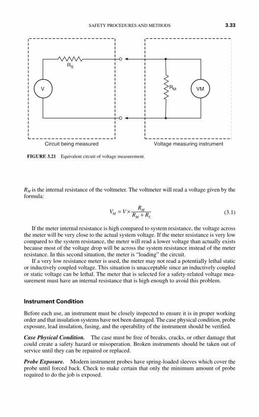
RM is the internal resistance of the voltmeter. The voltmeter will read a voltage given by theformula:
(3.1)
If the meter internal resistance is high compared to system resistance, the voltage acrossthe meter will be very close to the actual system voltage. If the meter resistance is very lowcompared to the system resistance, the meter will read a lower voltage than actually existsbecause most of the voltage drop will be across the system resistance instead of the meterresistance. In this second situation, the meter is “loading” the circuit.
If a very low resistance meter is used, the meter may not read a potentially lethal staticor inductively coupled voltage. This situation is unacceptable since an inductively coupledor static voltage can be lethal. The meter that is selected for a safety-related voltage mea-surement must have an internal resistance that is high enough to avoid this problem.
Instrument Condition
Before each use, an instrument must be closely inspected to ensure it is in proper workingorder and that insulation systems have not been damaged. The case physical condition, probeexposure, lead insulation, fusing, and the operability of the instrument should be verified.
Case Physical Condition. The case must be free of breaks, cracks, or other damage thatcould create a safety hazard or misoperation. Broken instruments should be taken out ofservice until they can be repaired or replaced.
Probe Exposure. Modern instrument probes have spring-loaded sleeves which cover theprobe until forced back. Check to make certain that only the minimum amount of proberequired to do the job is exposed.
V VR
R RMM
M S= × +
SAFETY PROCEDURES AND METHODS 3.33
V VM
RS
RM
Circuit being measured Voltage measuring instrument
FIGURE 3.21 Equivalent circuit of voltage measurement.
3.34 CHAPTER THREE
Lead Insulation Quality. Carefully inspect the lead insulation to make certain it is notdamaged in any way.
Fusing. Accessible fuses should be checked to be certain that they are correctly installedand have not been replaced by incorrect units.
Operability. Before each usage (at the beginning of each shift, for example), the instru-ment should be checked to make certain that it is operable. Do not substitute this check forthe instrument checks required in the three-step process.
Three-Step Measurement Process
Step 1—Test the Instrument. Immediately before each measurement, the instrumentshould be checked on a source which is known to be hot. This step confirms that the instru-ment is working before the actual circuit verification is made.
The preferred method is to use an actual power system conductor of the same voltage asthat being verified. Finding such a circuit is easier when low-voltage measurements arebeing made; however, even then a hot circuit may not be available. Some manufacturerssupply a device which creates a voltage that is sufficient for testing the instrument.
Some instruments intended for measurement of medium voltages have a low-voltageswitch setting on them which allows them to be checked on low voltage. This is not a preferredmethod since a problem with the switch could give erroheous, dangerous false readings.
Step 2—Measure the Circuit Being Verified. After the instrument is tested, the workerthen measures the circuit being verified to make certain it is de-energized. The actual wiresthat should be measured and the techniques to be used are discussed later in this chapter.
Step 3—Retest the Instrument. After the circuit has been verified, the instrument shouldbe rechecked as it was in step 1. This ensures that the instrument was operable both beforeand after the measurement, thus affirming that a zero measurement is zero and not causedby an inoperable instrument.
What to Measure
As a general rule of thumb, all normally energized conductors should be measured toground and to each other. The readings to ground should be made whether the system isgrounded or not. Note that all readings should be made as close to the point of exposure aspossible.
The procedures given in the following paragraphs will apply only to contact type instru-ments. Proximity instruments measure the electrostatic field set up around an energizedconductor rather than the actual voltage between two conductors. If the proximity indica-tor shows an unexpected voltage, the circuit should be rechecked, possibly with a contacttester.
Single-Phase Systems. The hot wire of single-phase systems should be measured bothagain neutral and ground. Figure 3.22 shows the points which should be measured.
Two-Phase Systems. A voltage measurement should be taken between the two hotphases, between each hot phase and neutral (one at a time), and between each hot phase andground. Figure 3.23 shows the measurement locations for a typical two-phase system.
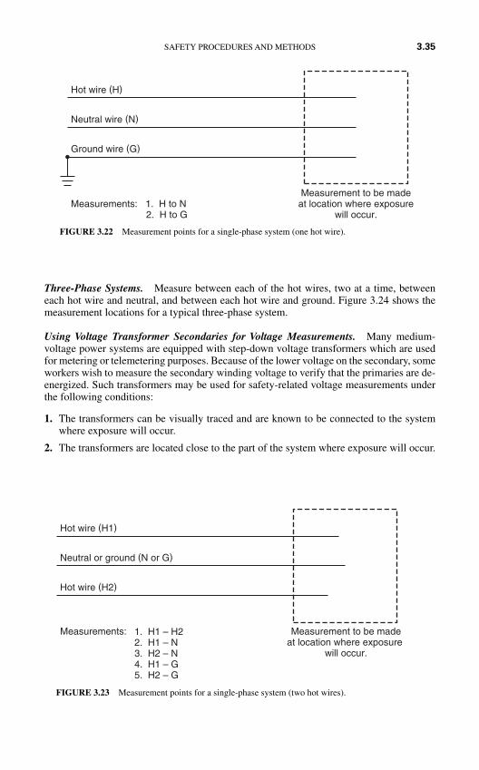
Three-Phase Systems. Measure between each of the hot wires, two at a time, betweeneach hot wire and neutral, and between each hot wire and ground. Figure 3.24 shows themeasurement locations for a typical three-phase system.
Using Voltage Transformer Secondaries for Voltage Measurements. Many medium-voltage power systems are equipped with step-down voltage transformers which are usedfor metering or telemetering purposes. Because of the lower voltage on the secondary, someworkers wish to measure the secondary winding voltage to verify that the primaries are de-energized. Such transformers may be used for safety-related voltage measurements underthe following conditions:
1. The transformers can be visually traced and are known to be connected to the systemwhere exposure will occur.
2. The transformers are located close to the part of the system where exposure will occur.
SAFETY PROCEDURES AND METHODS 3.35
Hot wire (H)
Neutral wire (N)
Ground wire (G)
Measurement to be madeat location where exposure
will occur.Measurements: 1. H to N 2. H to G
FIGURE 3.22 Measurement points for a single-phase system (one hot wire).
1. H1 – H22. H1 – N3. H2 – N4. H1 – G5. H2 – G
Hot wire (H1)
Neutral or ground (N or G)
Hot wire (H2)
Measurement to be madeat location where exposure
will occur.
Measurements:
FIGURE 3.23 Measurement points for a single-phase system (two hot wires).
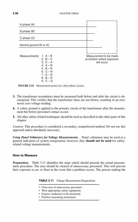
3. The transformer secondaries must be measured both before and after the circuit is de-energized. This verifies that the transformer fuses are not blown, resulting in an erro-neous zero voltage reading.
4. A safety ground is applied to the primary circuit of the transformer after the measure-ment but before personnel contact occurs.
5. All other safety-related techniques should be used as described in the other parts of thischapter.
Caution: This procedure is considered a secondary, nonpreferred method. Do not use thisapproach unless absolutely necessary.
Using Panel Voltmeters for Voltage Measurements. Panel voltmeters may be used as ageneral indication of system energization; however, they should not be used for safety-related voltage measurements.
How to Measure
Preparation. Table 3.11 identifies the steps which should precede the actual measure-ment procedure. The area should be cleared of unnecessary personnel. This will preventtheir exposure to arc or blast in the event that a problem occurs. The person making the
3.36 CHAPTER THREE
A phase (A)
B phase (B)
Neutral ground (N or G)
Measurement to be madeat location where exposure
will occur.
Measurements:
C phase (C)
1. A – B2. B – C3. C – A4. A – N5. B – N6. C – N7. A – G8. B – G9. C – G
FIGURE 3.24 Measurement points for a three-phase system.
• Clear area of unnecessary personnel.• Wear appropriate safety equipment.• Expose conductors to be measured.• Position measuring instrument.
TABLE 3.11 Voltage Measurement Preparations
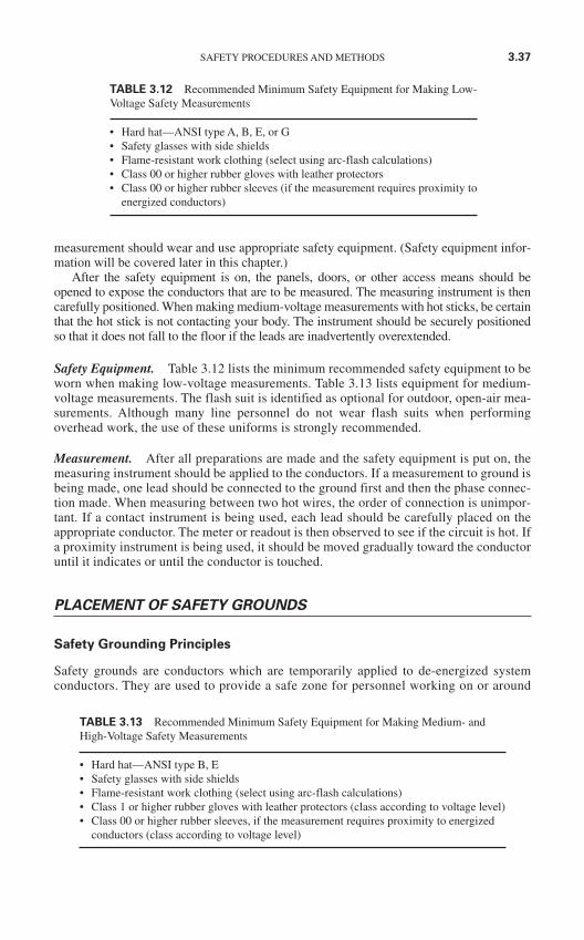
SAFETY PROCEDURES AND METHODS 3.37
measurement should wear and use appropriate safety equipment. (Safety equipment infor-mation will be covered later in this chapter.)
After the safety equipment is on, the panels, doors, or other access means should beopened to expose the conductors that are to be measured. The measuring instrument is thencarefully positioned. When making medium-voltage measurements with hot sticks, be certainthat the hot stick is not contacting your body. The instrument should be securely positionedso that it does not fall to the floor if the leads are inadvertently overextended.
Safety Equipment. Table 3.12 lists the minimum recommended safety equipment to beworn when making low-voltage measurements. Table 3.13 lists equipment for medium-voltage measurements. The flash suit is identified as optional for outdoor, open-air mea-surements. Although many line personnel do not wear flash suits when performingoverhead work, the use of these uniforms is strongly recommended.
Measurement. After all preparations are made and the safety equipment is put on, themeasuring instrument should be applied to the conductors. If a measurement to ground isbeing made, one lead should be connected to the ground first and then the phase connec-tion made. When measuring between two hot wires, the order of connection is unimpor-tant. If a contact instrument is being used, each lead should be carefully placed on theappropriate conductor. The meter or readout is then observed to see if the circuit is hot. Ifa proximity instrument is being used, it should be moved gradually toward the conductoruntil it indicates or until the conductor is touched.
PLACEMENT OF SAFETY GROUNDS
Safety Grounding Principles
Safety grounds are conductors which are temporarily applied to de-energized systemconductors. They are used to provide a safe zone for personnel working on or around
TABLE 3.12 Recommended Minimum Safety Equipment for Making Low-Voltage Safety Measurements
• Hard hat—ANSI type A, B, E, or G• Safety glasses with side shields• Flame-resistant work clothing (select using arc-flash calculations)• Class 00 or higher rubber gloves with leather protectors• Class 00 or higher rubber sleeves (if the measurement requires proximity to
energized conductors)
TABLE 3.13 Recommended Minimum Safety Equipment for Making Medium- andHigh-Voltage Safety Measurements
• Hard hat—ANSI type B, E• Safety glasses with side shields• Flame-resistant work clothing (select using arc-flash calculations)• Class 1 or higher rubber gloves with leather protectors (class according to voltage level)• Class 00 or higher rubber sleeves, if the measurement requires proximity to energized
conductors (class according to voltage level)
3.38 CHAPTER THREE
de-energized conductors and to ensure that an accidental reenergization will not cause injury.Power system components should be considered to be energized until safety grounds are inplace. Safety grounds should never be placed until the conductors where they are to beinstalled have been measured and verified to be de-energized.
See Chap. 2 for a detailed description of the design and description of safety grounds.Caution: Safety grounds must be properly designed and sized for the conductors and shortcircuit capacity to which they may be subjected. Refer to Chap. 2 and/or manufacturer’sinformation for specifics.
In the event that the system is accidently reenergized, enormous magnetic forces areexerted on the safety ground wires. The forces can cause the grounds to whip violently andcause injury to personnel. To minimize this effect the safety grounds should be as short as pos-sible, and the conductors should be restrained.
Safety Grounding Location
Equipotential Grounding. Safety grounds should be applied in such a way that a zone ofequal potential is formed in the work area. This equipotential zone is formed when fault cur-rent is bypassed around the work area by metallic conductors. Figure 3.25 shows the properlocation of safety grounds for three different work situations. In each of these situations, theworker is bypassed by the low-resistance metallic conductors of the safety ground.
Assume the worker contacts the center phase in Fig. 3.25b. With a fault current capac-ity of 10,000 A, safety ground resistance (Rj) of 0.001 Ω, and worker resistance (Rw) of500 Ω, the worker will receive only about 20 mA of current flow.
Figure 3.26a through d shows two nonpreferred or incorrect locations for the applica-tion of safety grounds. In these diagrams, the worker’s body is in parallel with the seriescombination of the jumper resistance (Rj) and the ground resistance (Rg). The placement ofgrounds in this fashion greatly increases the voltage drop across the worker’s body in theevent the circuit is reenergized. Such placements should not be used.
Single-Point versus Two-Point Grounding. Single-point grounding is the placement ofonly one safety ground set. In this procedure, the safety grounds are placed as close to thepoint of work as is possible. When possible, the grounds are placed between the worker andthe source of electric energy.
Two-point grounding is the placement of two safety ground sets. They are usuallyplaced on opposite sides of the work area; that is, one set is placed “upstream” and one setis placed “downstream” from the workers.
In general, more safety ground sets are better than fewer; however, the safety groundsystem must provide a zone of equal potential as described in the previous section.
Application of Safety Grounds
Safety Equipment. Table 3.14 lists the minimum recommended safety equipment thatshould be worn and used when applying safety grounds. Full shock, arc, and blast protec-tive clothing is required. No matter how carefully the work area is prepared, the possibilitystill exists for error and/or inadvertent reenergization during the application process.
Notice also that hot sticks are recommended for the actual application process. The useof hot sticks distances the worker from the point of contact and, therefore, minimizes thepossibility of injury caused by arc or blast.
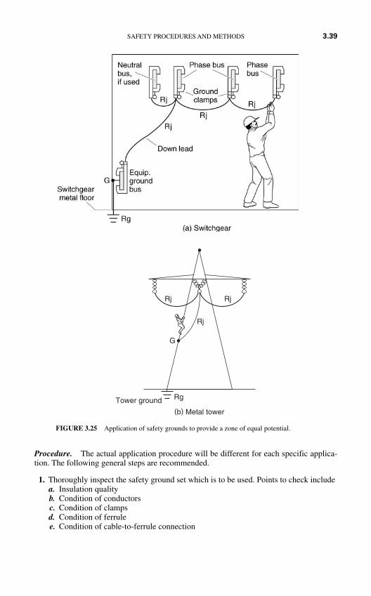
Procedure. The actual application procedure will be different for each specific applica-tion. The following general steps are recommended.
1. Thoroughly inspect the safety ground set which is to be used. Points to check includea. Insulation qualityb. Condition of conductorsc. Condition of clampsd. Condition of ferrulee. Condition of cable-to-ferrule connection
SAFETY PROCEDURES AND METHODS 3.39
Rj
RjRj
G
RgTower ground
(b) Metal tower
FIGURE 3.25 Application of safety grounds to provide a zone of equal potential.
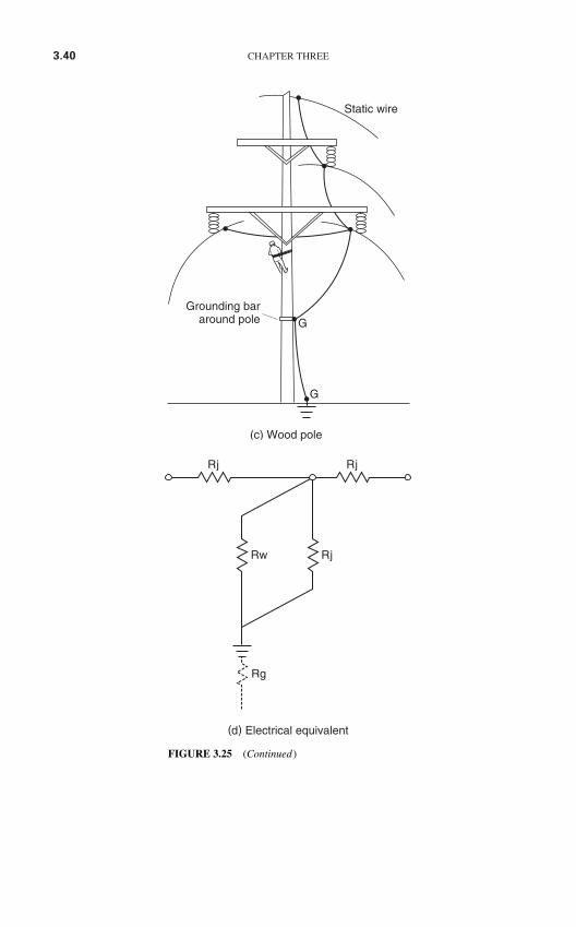
3.40 CHAPTER THREE
RjRw
Rg
Rj Rj
(d) Electrical equivalent
FIGURE 3.25 (Continued)
(c) Wood pole
Static wire
Grounding bararound pole G
G
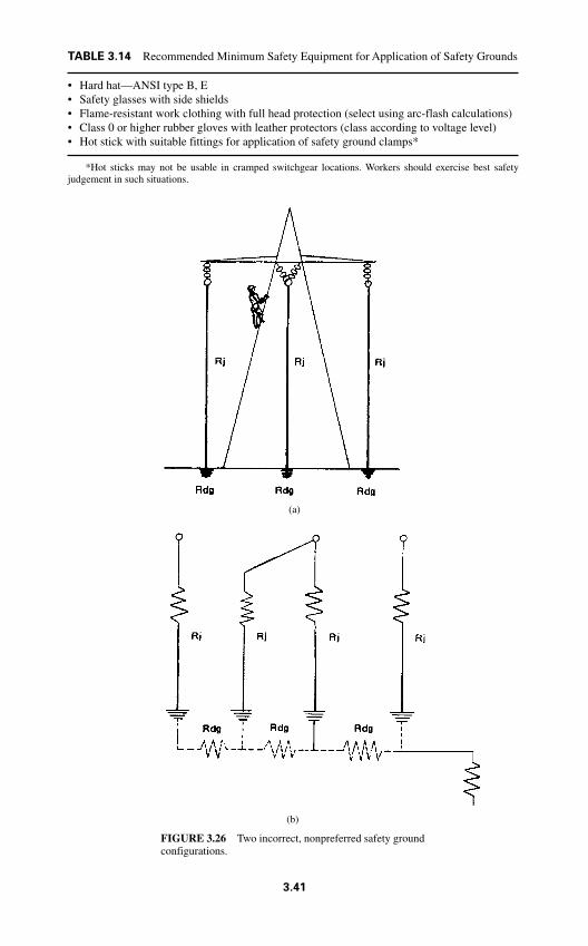
(b)
FIGURE 3.26 Two incorrect, nonpreferred safety groundconfigurations.
(a)
TABLE 3.14 Recommended Minimum Safety Equipment for Application of Safety Grounds
• Hard hat—ANSI type B, E• Safety glasses with side shields• Flame-resistant work clothing with full head protection (select using arc-flash calculations)• Class 0 or higher rubber gloves with leather protectors (class according to voltage level)• Hot stick with suitable fittings for application of safety ground clamps*
*Hot sticks may not be usable in cramped switchgear locations. Workers should exercise best safetyjudgement in such situations.
3.41
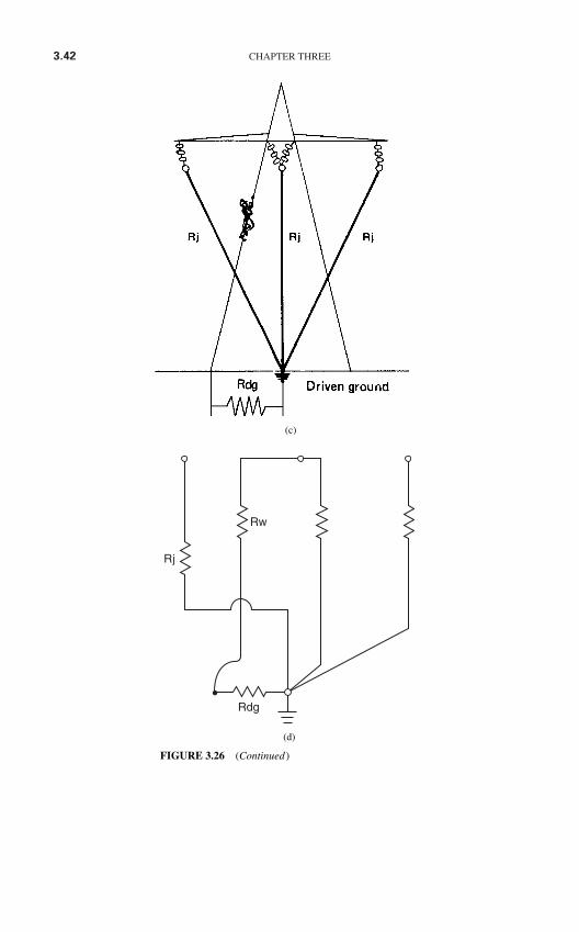
3.42 CHAPTER THREE
Rw
Rj
Rdg
(d)
FIGURE 3.26 (Continued)
(c)
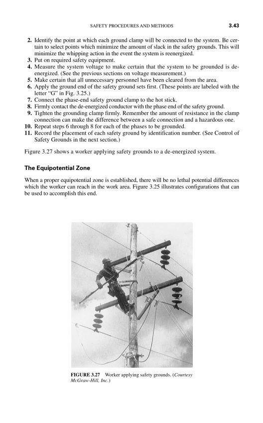
2. Identify the point at which each ground clamp will be connected to the system. Be cer-tain to select points which minimize the amount of slack in the safety grounds. This willminimize the whipping action in the event the system is reenergized.
3. Put on required safety equipment.4. Measure the system voltage to make certain that the system to be grounded is de-
energized. (See the previous sections on voltage measurement.)5. Make certain that all unnecessary personnel have been cleared from the area.6. Apply the ground end of the safety ground sets first. (These points are labeled with the
letter “G” in Fig. 3.25.)7. Connect the phase-end safety ground clamp to the hot stick.8. Firmly contact the de-energized conductor with the phase end of the safety ground.9. Tighten the grounding clamp firmly. Remember the amount of resistance in the clamp
connection can make the difference between a safe connection and a hazardous one.10. Repeat steps 6 through 8 for each of the phases to be grounded.11. Record the placement of each safety ground by identification number. (See Control of
Safety Grounds in the next section.)
Figure 3.27 shows a worker applying safety grounds to a de-energized system.
The Equipotential Zone
When a proper equipotential zone is established, there will be no lethal potential differenceswhich the worker can reach in the work area. Figure 3.25 illustrates configurations that canbe used to accomplish this end.
SAFETY PROCEDURES AND METHODS 3.43
FIGURE 3.27 Worker applying safety grounds. (CourtesyMcGraw-Hill, Inc.)
Note however, that some situations make the establishment of such a zone difficult orimpossible. Consider, for example, the employee who must stand on the earth when he orshe is working. Since the earth has a relatively high resistivity, the worker’s feet will be at adifferent potential from that of the metallic elements that he must contact.
There are two approaches that can be used in such circumstances:
1. A metal platform can be laid on the ground and bonded to the grounded metal of theelectrical system. Figure 3.18 is an example of this approach. In this situation, as longas the worker stays on the metal pad, he or she will remain in an equipotential zone.
2. The worker can be insulated from the earth or other high resistivity conductors. Rubbermats, gloves, or blankets can be placed so that the worker is completely insulated fromelectrical contact.
Of course, the best approach is always to establish the equipotential zone; however,these two “work-around” approaches may be used when absolutely necessary.
Removal of Safety Grounds
Safety Equipment. The removal of safety grounds is no less hazardous than applyingthem. All the safety equipment listed in Table 3.14 should be worn. Safety grounds shouldbe removed using hot sticks.
Procedure. Safety grounds should be removed as follows:
1. Put on all required safety equipment.
2. Remove each of the phase connections one at a time.
3. Remove the ground connection.
4. Check the ground off as being removed.
Remember that when safety grounds are not present, the system should be considered to beenergized.
Control of Safety Grounds
Safety grounds must be removed before the power system is reenergized. They must alsobe inspected periodically and before each use. The following sections describe two meth-ods of controlling the safety ground sets.
Inventory Method. Each safety ground set should be identified with its own unique serialnumber. The serial number should be etched or impressed on a metal tag which is perma-nently attached to the safety ground set.
A safety officer should be appointed to control the inventory of safety ground sets. Thisperson will control the use of the safety grounds and is responsible for keeping lists ofwhere the grounds are applied during an outage.
As each safety ground is applied, the safety officer notes its placement on a placement con-trol sheet. As each ground is removed, the officer notes its removal on the sheet. No reener-gization is allowed until the safety officer is satisfied that all safety grounds have beenremoved. Figure 3.28 is a typical safety ground placement control sheet.
The sheet shown in Fig. 3.28 has the minimum required information. Other columns—such as where the ground set is installed, who installed it, and who removed it—may be addedas needed.
3.44 CHAPTER THREE
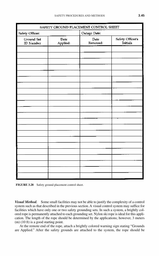
SAFETY PROCEDURES AND METHODS 3.45
Visual Method. Some small facilities may not be able to justify the complexity of a controlsystem such as that described in the previous section. A visual control system may suffice forfacilities which have only one or two safety grounding sets. In such a system, a brightly col-ored rope is permanently attached to each grounding set. Nylon ski rope is ideal for this appli-cation. The length of the rope should be determined by the applications; however, 3 meters(m) (10 ft) is a good starting point.
At the remote end of the rope, attach a brightly colored warning sign stating “Groundsare Applied.” After the safety grounds are attached to the system, the rope should be
FIGURE 3.28 Safety ground placement control sheet.
3.46 CHAPTER THREE
arranged on the switchgear so that it is easily seen. If it can be arranged, the rope shouldbe placed so the gear cannot be closed up until the rope is removed. The green sign shouldbe placed on the breaker control handle, start pushbutton, or other such device so that it isobviously visible.
When this procedure is used, it is very difficult to reenergize the system with the groundsin place. However, the inventory method is the preferred and recommended method.
FLASH HAZARD CALCULATIONS AND APPROACH DISTANCES
Introduction
How close to an electrical hazard can I get? Obviously, distance provides a safety barrierbetween a worker and an electrical hazard. As long as workers stay far enough away from anyelectrical energy sources, there is little or no chance of an electrical injury. This sectiondescribes methods that can be used to determine the so-called approach distances. Generally,if work can be carried on outside the approach distances, no personal protective equipment isrequired. If the worker must cross the approach distances, appropriate personal protectiveequipment must be worn and appropriate safety procedures must be used.
Approach Distance Definitions
Approach distances generally take two forms—shock hazard distance and flash hazard dis-tance. Note that the flash or arc hazard distance also includes the blast hazard distance.Figure 3.29 illustrates the approach distances that are defined by the NFPA in their publica-tion NFPA 70E Standard for Electrical Safety in the Workplaces 2000 Edition. Note that thespace inside any given boundary is named for that boundary. Thus the space inside therestricted approach boundary is referred to as the restricted space.
No approach boundary may be crossed without meeting the following generalrequirements:
1. The employee must be qualified to cross the boundary.
2. The employee must be wearing appropriate personal protective equipment.
3. Proper planning must be carried out to prepare the employee for the hazards he/she mayface.
Detailed requirements for each boundary will be given in later sections.
Determining Shock Hazard Approach Distances
Table 3.15 may be used to determine the minimum approach distances for employees forshock hazard purposes. Note that the shock approach distances are all based on voltage lev-els. In general, the higher the voltage level, the greater the approach distance.
Unqualified Persons. Unqualified persons may not approach exposed energized conduc-tors any closer than the values specified in columns (2) and (3) of Table 3.15. For unquali-fied persons the “limited” approach boundary is inviolable; that is, no unqualified person
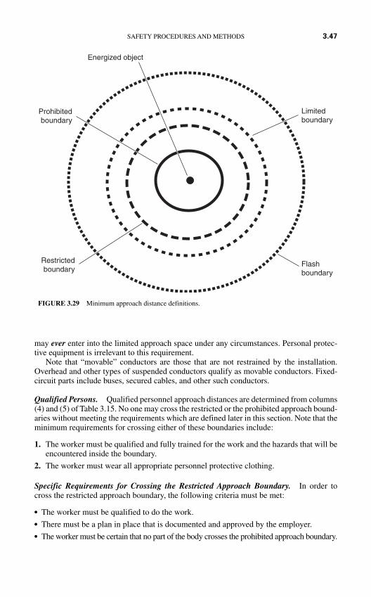
may ever enter into the limited approach space under any circumstances. Personal protec-tive equipment is irrelevant to this requirement.
Note that “movable” conductors are those that are not restrained by the installation.Overhead and other types of suspended conductors qualify as movable conductors. Fixed-circuit parts include buses, secured cables, and other such conductors.
Qualified Persons. Qualified personnel approach distances are determined from columns(4) and (5) of Table 3.15. No one may cross the restricted or the prohibited approach bound-aries without meeting the requirements which are defined later in this section. Note that theminimum requirements for crossing either of these boundaries include:
1. The worker must be qualified and fully trained for the work and the hazards that will beencountered inside the boundary.
2. The worker must wear all appropriate personnel protective clothing.
Specific Requirements for Crossing the Restricted Approach Boundary. In order tocross the restricted approach boundary, the following criteria must be met:
The worker must be qualified to do the work. There must be a plan in place that is documented and approved by the employer. The worker must be certain that no part of the body crosses the prohibited approach boundary.
SAFETY PROCEDURES AND METHODS 3.47
FIGURE 3.29 Minimum approach distance definitions.
Energized object
Prohibitedboundary
Restrictedboundary
Limitedboundary
Flashboundary
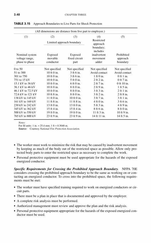
3.48 CHAPTER THREE
The worker must work to minimize the risk that may be caused by inadvertent movementby keeping as much of the body out of the restricted space as possible. Allow only pro-tected body parts to enter the restricted space as necessary to complete the work.
Personal protective equipment must be used appropriate for the hazards of the exposedenergized conductor.
Specific Requirements for Crossing the Prohibited Approach Boundary. NFPA 70Econsiders crossing the prohibited approach boundary to be the same as working on or con-tacting an energized conductor. To cross into the prohibited space, the following require-ments must be met:
The worker must have specified training required to work on energized conductors or cir-cuit parts.
There must be a plan in place that is documented and approved by the employer. A complete risk analysis must be performed. Authorized management must review and approve the plan and the risk analysis. Personal protective equipment appropriate for the hazards of the exposed energized con-
ductor must be used.
TABLE 3.15 Approach Boundaries to Live Parts for Shock Protection
(All dimensions are distance from live part to employee.)
(1) (2) (3) (4) (5)Restricted
Limited approach boundary approachboundary;includes
Nominal system Exposed Exposed inadvertent Prohibitedvoltage range, movable fixed circuit movement approachphase to phase conductor part adder boundary
0 to 50 Not specified Not specified Not specified Not specified51 to 300 10 ft 0 in. 3 ft 6 in. Avoid contact Avoid contact301 to 750 10 ft 0 in. 3 ft 6 in. 1 ft 0 in. 0 ft 1 in.751 to 15 kV 10 ft 0 in. 5 ft 0 in. 2 ft 2 in. 0 ft 7 in.15.1 kV to 36 kV 10 ft 0 in. 6 ft 0 in. 2 ft 7 in. 0 ft 10 in.36.1 kV to 46 kV 10 ft 0 in. 8 ft 0 in. 2 ft 9 in. 1 ft 5 in.46.1 kV to 72.5 kV 10 ft 0 in. 8 ft 0 in. 3 ft 3 in. 2 ft 1 in.72.6 kV to 121 kV 10 ft 8 in. 8 ft 0 in. 3 ft 2 in. 2 ft 8 in.138 kV to 145 kV 11 ft 0 in. 10 ft 0 in. 3 ft 7 in. 3 ft 1 in.161 kV to 169 kV 11 ft 8 in. 11 ft 8 in. 4 ft 0 in. 3 ft 6 in.230 kV to 242 kV 13 ft 0 in. 13 ft 0 in. 5 ft 3 in. 4 ft 9 in.345 kV to 362 kV 15 ft 4 in. 15 ft 4 in. 8 ft 6 in. 8 ft 0 in.500 kV to 550 kV 19 ft 0 in. 19 ft 0 in. 11 ft 3 in. 10 ft 9 in.765 kV to 800 kV 23 ft 9 in. 23 ft 9 in. 14 ft 11 in. 14 ft 5 in.
Notes:For SI units: 1 in. = 25.4 mm; 1 ft = 0.3048 m.Source: Courtesy National Fire Protection Association.
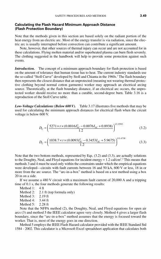
Calculating the Flash Hazard Minimum Approach Distance (Flash Protection Boundary)
Note that the methods given in this section are based solely on the radiant portion of theheat energy from an electric arc. Most of the energy transfer is via radiation, since the elec-tric arc is usually interrupted before convection can contribute a significant amount.
Note, however, that other sources of thermal injury can occur and are not accounted for inthese calculations. Flying molten material and/or superheated plasma can burn flesh severely.The clothing suggested in the handbook will help to provide some protection against suchevents.
Introduction. The concept of a minimum approach boundary for flash protection is basedon the amount of tolerance that human tissue has to heat. The current industry standards usethe so-called “Stoll Curve” developed by Stoll and Chianta in the 1960s.1 The flash boundarythen represents the closest distance that an unprotected (meaning not wearing thermal protec-tive clothing beyond normal cotton garments) worker may approach an electrical arcingsource. Theoretically, at the flash boundary distance, if an electrical arc occurs, the unpro-tected worker should receive no more than a curable, second-degree burn. Table 3.16 is areproduction of the Stoll Curve table.
Low-Voltage Calculations (Below 600 V). Table 3.17 illustrates five methods that may beused for calculating the minimum approach distances for electrical flash when the circuitvoltage is below 600 V.
(3.2)
(3.3)
Note that the two bottom methods, represented by Eqs. (3.2) and (3.3), are actually solutionsto the Doughty, Neal, and Floyd equations for incident energy = 1.2 cal/cm2.2 This means thatmethods 3 and 4 must be used only within the constraints under which the empirical equationswere developed—circuits with fault currents between 16 and 50 kA, 600 V or less, 18 in ormore from the arc source. The “arc-in-a-box” method is based on a test method using a box20 in on a side.
If we assume a 480 V circuit with a maximum fault current of 20,000 A and a trippingtime of 0.1 s, the four methods generate the following results:
Method 1: 4 ftMethod 2: 2.1 ft (top formula only)Method 3: 2.19 ftMethod 4: 3.44 ftMethod 5: 2.28 ftNote that the NFPA method (2), the Doughty, Neal, and Floyd equations for open air
arcs (3) and method 5 the IEEE calculator agree very closely. Method 4 gives a larger flashboundary, since the “arc-in-a-box” method assumes that the energy is focused toward theworker. That is, most of the energy goes in one direction.
Method 5 employs the IEEE Flash Hazard calculator provided with the IEEE Standard Std1584 - 2002. This calculator is a Microsoft Excel spreadsheet application that calculates both
D t I IC
SC SC= × × − +
1038 7 0 0093 0 3453 5 96751 2
2 1 1 4738. ( . . . )
.
/ .
D t I IC
SC SC= × × − +
5271 0 0016 0 0076 0 89381 2
2 1 1 9593( . . . )
.
/ .
SAFETY PROCEDURES AND METHODS 3.49
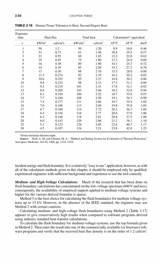
3.50 CHAPTER THREE
incident energy and flash boundary. It is a relatively “easy to use” application; however, as withall of the calculation methods given in this chapter, it should be employed only by qualified,experienced engineers with sufficient background and experience to use the tool correctly.
Medium- and High-Voltage Calculations. Much of the research that has been done onflash boundary calculations has concentrated on the low-voltage spectrum (600 V and less);consequently, the availability of empirical support applied to medium voltage systems andhigher for the various derived formulas is sparse.
Method 5 is the best choice for calculating the flash boundaries for medium voltage sys-tems up to 15 kV. However, in the absence of the IEEE standard, the engineer may useMethod 2 with certain cautions.
Calculating medium- and high-voltage flash boundaries using Method 2 (Table 3.17)appears to give conservatively high results when compared to software programs derivedusing industry standard heat transfer calculations.
To calculate the flash boundary for medium-voltage systems, use the top formula givenin Method 2. Then enter the result into one of the commercially available (or freeware) soft-ware programs and verify that the received heat flux density is on the order of 1.2 cal/cm2.
TABLE 3.16 Human Tissue Tolerance to Heat, Second-Degree Burn
Exposuretime Heat flux Total heat Calorimeter* equivalent
s kW/m2 cal/cm2s kWs/m2 cal/cm2 ∆T°C ∆T°F ∆mV
1 50 1.2 50 1.20 8.9 16.0 0.462 31 0.73 61 1.46 10.8 19.5 0.573 23 0.55 69 1.65 12.2 22.0 0.634 19 0.45 75 1.80 13.3 24.0 0.695 16 0.38 80 1.90 14.1 25.3 0.726 14 0.34 85 2.04 15.1 27.2 0.787 13 0.30 88 2.10 15.5 28.0 0.808 11.5 0.274 92 2.19 16.2 29.2 0.839 10.6 0.252 95 2.27 16.8 30.2 0.86
10 9.8 0.233 98 2.33 17.3 31.1 0.8911 9.2 0.219 101 2.41 17.8 32.1 0.9212 8.6 0.205 103 2.46 18.2 32.8 0.9413 8.1 0.194 106 2.52 18.7 33.6 0.9714 7.7 0.184 108 2.58 19.1 34.3 0.9915 7.4 0.177 111 2.66 19.7 35.4 1.0216 7.0 0.168 113 2.69 19.8 35.8 1.0317 6.7 0.160 114 2.72 20.2 36.3 1.0418 6.4 0.154 116 2.77 20.6 37.0 1.0619 6.2 0.148 118 2.81 20.8 37.5 1.0820 6.0 0.143 120 2.86 21.2 38.1 1.1025 5.1 0.122 128 3.05 22.6 40.7 1.1730 4.5 0.107 134 3.21 23.8 42.8 1.23
*Iron/constantan thermocouple.Source: Stoll, A. M. and Chianta, M. A., “Method and Rating System for Evaluation of Thermal Protection,”
Aerospace Medicine, Vol 40, 1968, pp. 1232–1238.
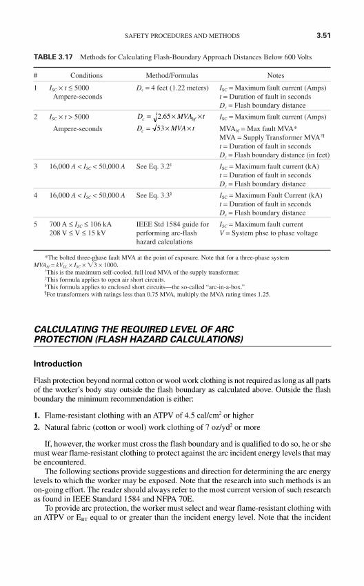
SAFETY PROCEDURES AND METHODS 3.51
TABLE 3.17 Methods for Calculating Flash-Boundary Approach Distances Below 600 Volts
# Conditions Method/Formulas Notes
1 ISC × t ≤ 5000 Dc = 4 feet (1.22 meters) ISC = Maximum fault current (Amps)Ampere-seconds t = Duration of fault in seconds
Dc = Flash boundary distance
2 ISC × t > 5000 ISC = Maximum fault current (Amps)
Ampere-seconds MVAbf = Max fault MVA*MVA = Supply Transformer MVA†¶
t = Duration of fault in secondsDc = Flash boundary distance (in feet)
3 16,000 A < ISC < 50,000 A See Eq. 3.2‡ ISC = Maximum fault current (kA)t = Duration of fault in secondsDc = Flash boundary distance
4 16,000 A < ISC < 50,000 A See Eq. 3.3§ ISC = Maximum Fault Current (kA)t = Duration of fault in secondsDc = Flash boundary distance
5 700 A ≤ ISC ≤ 106 kA IEEE Std 1584 guide for ISC = Maximum fault current208 V ≤ V ≤ 15 kV performing arc-flash V = System phse to phase voltage
hazard calculations
*The bolted three-phase fault MVA at the point of exposure. Note that for a three-phase system MVAbf = kVLL × ISC × 3 × 1000.
†This is the maximum self-cooled, full load MVA of the supply transformer.‡This formula applies to open air short circuits.§This formula applies to enclosed short circuits—the so-called “arc-in-a-box.”¶For transformers with ratings less than 0.75 MVA, multiply the MVA rating times 1.25.
D MVA tc = × ×53
D MVA tc bf= × ×2 65.
CALCULATING THE REQUIRED LEVEL OF ARCPROTECTION (FLASH HAZARD CALCULATIONS)
Introduction
Flash protection beyond normal cotton or wool work clothing is not required as long as all partsof the worker’s body stay outside the flash boundary as calculated above. Outside the flashboundary the minimum recommendation is either:
1. Flame-resistant clothing with an ATPV of 4.5 cal/cm2 or higher
2. Natural fabric (cotton or wool) work clothing of 7 oz/yd2 or more
If, however, the worker must cross the flash boundary and is qualified to do so, he or shemust wear flame-resistant clothing to protect against the arc incident energy levels that maybe encountered.
The following sections provide suggestions and direction for determining the arc energylevels to which the worker may be exposed. Note that the research into such methods is anon-going effort. The reader should always refer to the most current version of such researchas found in IEEE Standard 1584 and NFPA 70E.
To provide arc protection, the worker must select and wear flame-resistant clothing withan ATPV or EBT equal to or greater than the incident energy level. Note that the incident
3.52 CHAPTER THREE
energy level is calculated based on a given distance between the arc source and the worker,for example 24 inches. The worker will not be adequately protected if he or she gets anycloser than the distance used in the calculation for the specific situation.
Flash boundaries can be calculated from the formulas in this section by setting the inci-dent energy level to 1.2 cal/cm2 (5.02 J/cm2) and then solving the appropriate equation forthe distance.
Caution: The following sections present several complex calculation procedures usinga variety of mathematical and engineering applications. These calculations should be per-formed or evaluated only by qualified, experienced engineers or other such technical per-sonnel with the requisite knowledge and skills.
The Lee Method
This method is named after its developer Ralph Lee, PE (deceased). Mr. Lee was one of theearly, and most successful researchers into the theoretical models for the amount of energycreated by an electrical arc and the amount of incident energy received by workers in thevicinity of the arc.
The Lee method is based on two major assumptions:
1. The maximum energy transfer from the power system to an electric arc is equal to one-half of the bolted short-circuit power available at the point where the arc occurs.
2. All of the arc electrical energy will be converted to the incident heat energy.
Starting with these two assumptions, Mr. Lee and subsequent researchers have refinedthe Lee method to the form shown in equation 3.4
(3.4)
Where E = the incident energy (J/cm2 or cal/cm2 depending on the value of K)K = a constant. If K = 2.142 then E is in J/cm2. If K = 0.512 then E is in cal/cm2.V = the system phase-to-phase voltage (kV)
Ibf = the bolted fault current (kA)t = the arcing time (seconds)
D = the distance from the arcing point to the worker (mm)
The Lee method is a very conservative method and was developed without the aid of theempirical results available today from the extensive research in this field. While it can beused for all situations, its principle application is in those cases that have not been modeledbased on actual experimental measurements. It is most often used in systems where the sys-tem voltage is greater than 600 V and/or where fault currents, arc lengths, or other suchparameters are beyond the ranges that have been tested using field measurements.
Although the Lee method does not take the focusing effect of equipment into account,the so-called arc-in-a-box, it is very conservative. The use of multipliers should be requiredonly in the most extreme applications.
Methods Outlined in NFPA 70E
In addition to the LEE method, the 2004 Edition of NFPA 70E, Standard for ElectricalSafety in the Workplace gives two different methods for calculating incident energy levels.
E K VIt
Dbf= ×
×
2610
SAFETY PROCEDURES AND METHODS 3.53
Method #1. This method is based on a research by Richard L. Doughty, Thomas E. Neal,and H. Landis Floyd.2 They performed research using the thermal manikin approachdescribed in Chap. 1. Their research was bounded by the following conditions:
1. Systems with voltage levels of 600 V and below
2. Systems with maximum available short circuit currents between 16 kA and 50 kA.
3. Working distances of equal to or greater than 18 inches.
After running numerous tests by creating electric arcs in open air, they took their resultsand performed a curve fit to predict the incident energy. Equation 3.5 is the formula thatwas developed and which most closely models the energies they measured.
EMA = 5271DA−1.9593 × tA(0.0016I2
SC − 0.0076ISC + 0.8938) (3.5)
Where EMA = the maximum open air arc incident energy (cal/cm2)DA = the distance from the electrodes (in)—note that DA ≥ 18 intA = the duration of the arc (seconds)
ISC = the short circuit current (kA)—note that ISC is the actual arc current, not themaximum bolted fault current.
In the second part of their research they created electrical arcs in a cubic box with oneopen side. The box was 20 inches on a side and the measurements were taken at various dis-tances from the open end. They then performed a curve fit to model the results. Equation3.6 is the resulting formula.
EMB = 1038.7DB−1.4738 × tA(0.0093I2
SC − 0.3453ISC + 5.9675) (3.6)
Where EMB = the maximum arc-in-a-box incident energy (cal/cm2)DB = the distance from the electrodes (in)—note that DB ≥ 18 in
All other variables are as described for the open air formula (Eq. 3.5)Using either Eqs. 3.5 or 3.6, incident energies can be calculated, then protective cloth-
ing can be purchased with the necessary ratings.
Method #2. Method number two is actually the method taken from the IEEE Standard1584-2002.3 This method is described in the next section.
IEEE Standard Std 1584-2002
System Model Limitations. Institute of Electrical & Electronics Engineers (IEEE) work-ing group P1584 has performed research and theory development over several years toexpand the work done by Doughty, et al.2 As shown in Table 3.18, the working group hassignificantly expanded the applicable range for the application of their methods.
Calculation of Arcing Current. One of the principal drawbacks of the Lee method is thatthe bolted fault current, which is used in that method, is always somewhat greater than theactual current flow when an electrical arc is formed. At voltages below 1000 V, the arcingcurrent is often substantially less than the bolted fault current.
Using both theoretical and empirical data, Standard 1584, develops a formula to calcu-late the arcing current that will present in a system when the bolted fault current is known.Equations 3.7, and 3.8 are used to calculate the logarithm to the base ten of arcing current
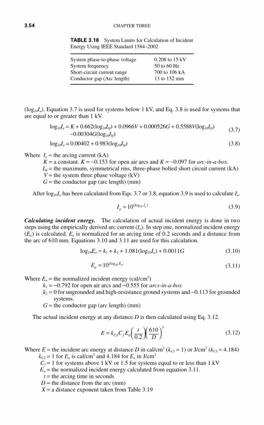
(log10Ia). Equation 3.7 is used for systems below 1 kV, and Eq. 3.8 is used for systems thatare equal to or greater than 1 kV.
log10Ia = K + 0.662(log10Ibf) + 0.0966V + 0.000526G + 0.5588V(log10Ibf) (3.7)−0.00304G(log10Ibf)
log10Ia = 0.00402 + 0.983(log10Ibf) (3.8)
Where Ia = the arcing current (kA)K = a constant. K = −0.153 for open air arcs and K = −0.097 for arc-in-a-box.Ibf = the maximum, symmetrical rms, three-phase bolted short circuit current (kA)V = the system three phase voltage (kV)G = the conductor gap (arc length) (mm)
After log10Ia has been calculated from Eqs. 3.7 or 3.8, equation 3.9 is used to calculate Ia.
(3.9)
Calculating incident energy. The calculation of actual incident energy is done in twosteps using the empirically derived arc current (Ia). In step one, normalized incident energy(En) is calculated. En is normalized for an arcing time of 0.2 seconds and a distance fromthe arc of 610 mm. Equations 3.10 and 3.11 are used for this calculation.
log10En = k1 + k2 + 1.081(log10Ia) + 0.0011G (3.10)
(3.11)
Where En = the normalized incident energy (cal/cm2)k1 = −0.792 for open air arcs and −0.555 for arcs-in-a-boxk2 = 0 for ungrounded and high-resistance ground systems and −0.113 for grounded
systems.G = the conductor gap (arc length) (mm)
The actual incident energy at any distance D is then calculated using Eq. 3.12.
(3.12)
Where E = the incident arc energy at distance D in cal/cm2 (kCJ = 1) or J/cm2 (kCJ = 4.184)kCJ = 1 for En is cal/cm2 and 4.184 for En in J/cm2
Cf = 1 for systems above 1 kV or 1.5 for systems equal to or less than 1 kVEn = the normalized incident energy calculated from equation 3.11.
t = the arcing time in secondsD = the distance from the arc (mm)X = a distance exponent taken from Table 3.19
E k C E tDCJ f n
X
=
0 2
610.
EnEn= 10 10(log )
IaIa= 10 10(log )
3.54 CHAPTER THREE
TABLE 3.18 System Limits for Calculation of IncidentEnergy Using IEEE Standard 1584–2002
System phase-to-phase voltage 0.208 to 15 kVSystem frequency 50 to 60 HzShort-circuit current range 700 to 106 kAConductor gap (Arc length) 13 to 152 mm
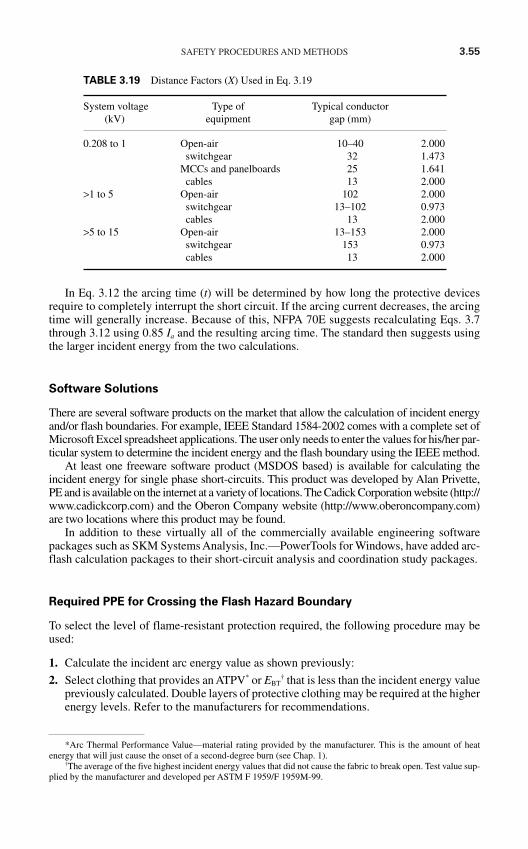
SAFETY PROCEDURES AND METHODS 3.55
In Eq. 3.12 the arcing time (t) will be determined by how long the protective devicesrequire to completely interrupt the short circuit. If the arcing current decreases, the arcingtime will generally increase. Because of this, NFPA 70E suggests recalculating Eqs. 3.7through 3.12 using 0.85 Ia and the resulting arcing time. The standard then suggests usingthe larger incident energy from the two calculations.
Software Solutions
There are several software products on the market that allow the calculation of incident energyand/or flash boundaries. For example, IEEE Standard 1584-2002 comes with a complete set ofMicrosoft Excel spreadsheet applications. The user only needs to enter the values for his/her par-ticular system to determine the incident energy and the flash boundary using the IEEE method.
At least one freeware software product (MSDOS based) is available for calculating theincident energy for single phase short-circuits. This product was developed by Alan Privette,PE and is available on the internet at a variety of locations. The Cadick Corporation website (http://www.cadickcorp.com) and the Oberon Company website (http://www.oberoncompany.com)are two locations where this product may be found.
In addition to these virtually all of the commercially available engineering softwarepackages such as SKM Systems Analysis, Inc.—PowerTools for Windows, have added arc-flash calculation packages to their short-circuit analysis and coordination study packages.
Required PPE for Crossing the Flash Hazard Boundary
To select the level of flame-resistant protection required, the following procedure may beused:
1. Calculate the incident arc energy value as shown previously:
2. Select clothing that provides an ATPV* or EBT† that is less than the incident energy value
previously calculated. Double layers of protective clothing may be required at the higherenergy levels. Refer to the manufacturers for recommendations.
TABLE 3.19 Distance Factors (X) Used in Eq. 3.19
System voltage Type of Typical conductor (kV) equipment gap (mm)
0.208 to 1 Open-air 10–40 2.000switchgear 32 1.473
MCCs and panelboards 25 1.641cables 13 2.000
>1 to 5 Open-air 102 2.000switchgear 13–102 0.973cables 13 2.000
>5 to 15 Open-air 13–153 2.000switchgear 153 0.973cables 13 2.000
*Arc Thermal Performance Value—material rating provided by the manufacturer. This is the amount of heatenergy that will just cause the onset of a second-degree burn (see Chap. 1).
†The average of the five highest incident energy values that did not cause the fabric to break open. Test value sup-plied by the manufacturer and developed per ASTM F 1959/F 1959M-99.
3.56 CHAPTER THREE
A Simplified Approach to the Selection of Protective Clothing
The National Fire Protection Association provides a simplified approach to the selection of pro-tective clothing. While this method is convenient and economical, it should be used withextreme caution. The author has found specific situations when the simplified method doesnot yield the most conservative values, thus putting workers at risk.
Additionally, this method assumes certain short circuit and operating time values. Theuser must be absolutely certain that his or her power system falls within the assumed values.
1. Identify the Hazard/Risk category from Table 3.20. Note that this is based on the typeof work that will be performed. Note also that Table 3.20 identifies whether insulatinggloves and/or tools are required.
2. Use Table 3.21 to select the various types of PPE required for the hazard determined instep 1.
3. Use Table 3.22 to select the weight of flame-resistant clothing required for the task.
Although this procedure is quite simple and straightforward, it should be used carefullyfor at least two reasons:
Because it is conservative, it tends to result in substantial amounts of clothing for theemployee. Workers may tend to disregard necessary equipment out of frustration.
The standard is task-based as opposed to location-based. Using the quantitative methodsdescribed previously will provide, ultimately, a more easily applied set of rules.
In some rare cases, the simplified approach may give values that do not provide adequateprotection. This is especially critical if the limits imposed by the method are ignored.
BARRIERS AND WARNING SIGNS
Barriers and warning signs should be placed to control entrance into a work area wherethere are exposed energized conductors. The installation of such equipment will varydepending on the layout of the work area. The following general criteria should be applied:
The signs should be distinctive, easy to read, and posted at all entrances to the work area.The signs should clearly warn personnel of the hazardous or energized condition.
Barriers and barrier tape should be placed at a height that is easy to see. Three feet or sois a good starting point. Adjust the height as dictated by the specific installation.
Barriers and barrier tape should be placed so that equipment is not reachable from outsideof the barrier. This will prevent the accidental or intentional operation of equipment by per-sonnel not authorized to do so.
If sufficient work room is not available when barriers are placed, attendants should be usedto warn employees of the exposed hazards.
Figure 3.30a shows a sample arrangement for a work area in a switchgear room. Thelayout given here is for example only; however, the general principles may be used. Keypoints for this installation are
1. Stanchions are used to provide a firm structure for stringing the barrier tape.
2. Warning signs are placed at both entrances warning personnel that hazards exist inside.
3. Warning signs are also posted on the switchgear itself.
4. Five to ten feet of work clearance is allowed between the tape and the switchgear. Thisnumber may vary depending on the space available and the work to be performed.
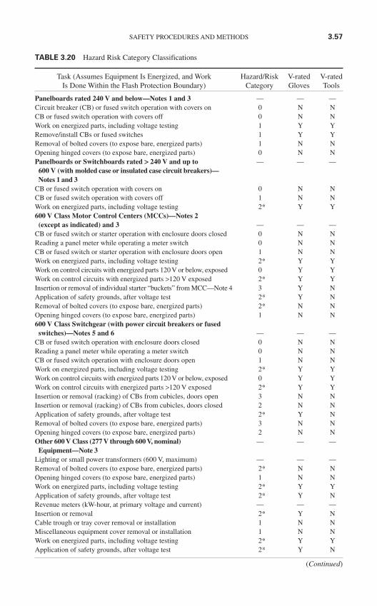
SAFETY PROCEDURES AND METHODS 3.57
TABLE 3.20 Hazard Risk Category Classifications
Task (Assumes Equipment Is Energized, and Work Hazard/Risk V-rated V-ratedIs Done Within the Flash Protection Boundary) Category Gloves Tools
Panelboards rated 240 V and below—Notes 1 and 3 — — —Circuit breaker (CB) or fused switch operation with covers on 0 N NCB or fused switch operation with covers off 0 N NWork on energized parts, including voltage testing 1 Y YRemove/install CBs or fused switches 1 Y YRemoval of bolted covers (to expose bare, energized parts) 1 N NOpening hinged covers (to expose bare, energized parts) 0 N NPanelboards or Switchboards rated > 240 V and up to — — —600 V (with molded case or insulated case circuit breakers)—Notes 1 and 3
CB or fused switch operation with covers on 0 N NCB or fused switch operation with covers off 1 N NWork on energized parts, including voltage testing 2* Y Y600 V Class Motor Control Centers (MCCs)—Notes 2
(except as indicated) and 3 — — —CB or fused switch or starter operation with enclosure doors closed 0 N NReading a panel meter while operating a meter switch 0 N NCB or fused switch or starter operation with enclosure doors open 1 N NWork on energized parts, including voltage testing 2* Y YWork on control circuits with energized parts 120 V or below, exposed 0 Y YWork on control circuits with energized parts >120 V exposed 2* Y YInsertion or removal of individual starter “buckets” from MCC—Note 4 3 Y NApplication of safety grounds, after voltage test 2* Y NRemoval of bolted covers (to expose bare, energized parts) 2* N NOpening hinged covers (to expose bare, energized parts) 1 N N600 V Class Switchgear (with power circuit breakers or fused
switches)—Notes 5 and 6 — — —CB or fused switch operation with enclosure doors closed 0 N NReading a panel meter while operating a meter switch 0 N NCB or fused switch operation with enclosure doors open 1 N NWork on energized parts, including voltage testing 2* Y YWork on control circuits with energized parts 120 V or below, exposed 0 Y YWork on control circuits with energized parts >120 V exposed 2* Y YInsertion or removal (racking) of CBs from cubicles, doors open 3 N NInsertion or removal (racking) of CBs from cubicles, doors closed 2 N NApplication of safety grounds, after voltage test 2* Y NRemoval of bolted covers (to expose bare, energized parts) 3 N NOpening hinged covers (to expose bare, energized parts) 2 N NOther 600 V Class (277 V through 600 V, nominal) — — —Equipment—Note 3
Lighting or small power transformers (600 V, maximum) — — —Removal of bolted covers (to expose bare, energized parts) 2* N NOpening hinged covers (to expose bare, energized parts) 1 N NWork on energized parts, including voltage testing 2* Y YApplication of safety grounds, after voltage test 2* Y NRevenue meters (kW-hour, at primary voltage and current) — — —Insertion or removal 2* Y NCable trough or tray cover removal or installation 1 N NMiscellaneous equipment cover removal or installation 1 N NWork on energized parts, including voltage testing 2* Y YApplication of safety grounds, after voltage test 2* Y N
(Continued)
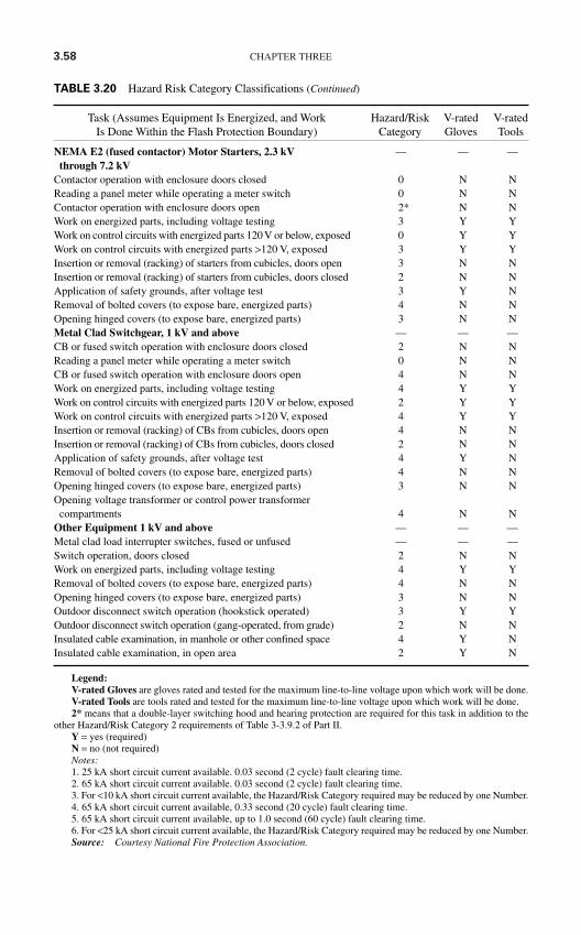
3.58 CHAPTER THREE
TABLE 3.20 Hazard Risk Category Classifications (Continued)
Task (Assumes Equipment Is Energized, and Work Hazard/Risk V-rated V-ratedIs Done Within the Flash Protection Boundary) Category Gloves Tools
NEMA E2 (fused contactor) Motor Starters, 2.3 kV — — —through 7.2 kV
Contactor operation with enclosure doors closed 0 N NReading a panel meter while operating a meter switch 0 N NContactor operation with enclosure doors open 2* N NWork on energized parts, including voltage testing 3 Y YWork on control circuits with energized parts 120 V or below, exposed 0 Y YWork on control circuits with energized parts >120 V, exposed 3 Y YInsertion or removal (racking) of starters from cubicles, doors open 3 N NInsertion or removal (racking) of starters from cubicles, doors closed 2 N NApplication of safety grounds, after voltage test 3 Y NRemoval of bolted covers (to expose bare, energized parts) 4 N NOpening hinged covers (to expose bare, energized parts) 3 N NMetal Clad Switchgear, 1 kV and above — — —CB or fused switch operation with enclosure doors closed 2 N NReading a panel meter while operating a meter switch 0 N NCB or fused switch operation with enclosure doors open 4 N NWork on energized parts, including voltage testing 4 Y YWork on control circuits with energized parts 120 V or below, exposed 2 Y YWork on control circuits with energized parts >120 V, exposed 4 Y YInsertion or removal (racking) of CBs from cubicles, doors open 4 N NInsertion or removal (racking) of CBs from cubicles, doors closed 2 N NApplication of safety grounds, after voltage test 4 Y NRemoval of bolted covers (to expose bare, energized parts) 4 N NOpening hinged covers (to expose bare, energized parts) 3 N NOpening voltage transformer or control power transformer
compartments 4 N NOther Equipment 1 kV and above — — —Metal clad load interrupter switches, fused or unfused — — —Switch operation, doors closed 2 N NWork on energized parts, including voltage testing 4 Y YRemoval of bolted covers (to expose bare, energized parts) 4 N NOpening hinged covers (to expose bare, energized parts) 3 N NOutdoor disconnect switch operation (hookstick operated) 3 Y YOutdoor disconnect switch operation (gang-operated, from grade) 2 N NInsulated cable examination, in manhole or other confined space 4 Y NInsulated cable examination, in open area 2 Y N
Legend:V-rated Gloves are gloves rated and tested for the maximum line-to-line voltage upon which work will be done.V-rated Tools are tools rated and tested for the maximum line-to-line voltage upon which work will be done.2* means that a double-layer switching hood and hearing protection are required for this task in addition to the
other Hazard/Risk Category 2 requirements of Table 3-3.9.2 of Part II.Y = yes (required)N = no (not required)Notes:1. 25 kA short circuit current available. 0.03 second (2 cycle) fault clearing time.2. 65 kA short circuit current available. 0.03 second (2 cycle) fault clearing time.3. For <10 kA short circuit current available, the Hazard/Risk Category required may be reduced by one Number.4. 65 kA short circuit current available, 0.33 second (20 cycle) fault clearing time.5. 65 kA short circuit current available, up to 1.0 second (60 cycle) fault clearing time.6. For <25 kA short circuit current available, the Hazard/Risk Category required may be reduced by one Number.Source: Courtesy National Fire Protection Association.
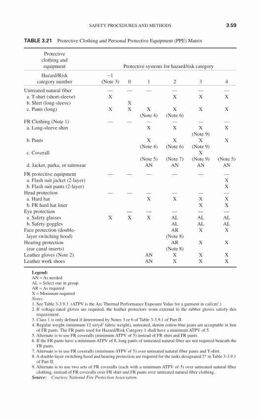
SAFETY PROCEDURES AND METHODS 3.59
TABLE 3.21 Protective Clothing and Personal Protective Equipment (PPE) Matrix
Protectiveclothing andequipment Protective systems for hazard/risk category
Hazard/Risk −1category number (Note 3) 0 1 2 3 4
Untreated natural fiber — — — — — —a. T-shirt (short-sleeve) X X X Xb. Shirt (long-sleeve) Xc. Pants (long) X X X X X X
(Note 4) (Note 6)FR Clothing (Note 1) — — — — — —
a. Long-sleeve shirt X X X X(Note 9)
b. Pants X X X X(Note 4) (Note 6) (Note 9)
c. Coverall X(Note 5) (Note 7) (Note 9) (Note 5)
d. Jacket, parka, or rainwear AN AN AN AN
FR protective equipment — — — — — —a. Flash suit jacket (2-layer) Xb. Flash suit pants (2-layer) X
Head protection — — — — — —a. Hard hat X X X Xb. FR hard hat liner X X
Eye protection — — — — —a. Safety glasses X X X AL AL ALb. Safety goggles AL AL AL
Face protection (double- AR X Xlayer switching hood) (Note 8)
Hearing protection AR X X(ear canal inserts) (Note 8)
Leather gloves (Note 2) AN X X XLeather work shoes AN X X X
Legend:AN = As neededAL = Select one in groupAR = As requiredX = Minimum requiredNotes:1. See Table 3-3.9.3. (ATPV is the Arc Thermal Performance Exposure Value for a garment in cal/cm2.)2. If voltage-rated gloves are required, the leather protectors worn external to the rubber gloves satisfy this
requirement.3. Class 1 is only defined if determined by Notes 3 or 6 of Table 3-3.9.1 of Part II.4. Regular weight (minimum 12 oz/yd2 fabric weight), untreated, denim cotton blue jeans are acceptable in lieu
of FR pants. The FR pants used for Hazard/Risk Category 1 shall have a minimum ATPV of 5.5. Alternate is to use FR coveralls (minimum ATPV of 5) instead of FR shirt and FR pants.6. If the FR pants have a minimum ATPV of 8, long pants of untreated natural fiber are not required beneath the
FR pants.7. Alternate is to use FR coveralls (minimum ATPV of 5) over untreated natural fiber pants and T-shirt.8. A double-layer switching hood and hearing protection are required for the tasks designated 2* in Table 3-3.9.1
of Part II.9. Alternate is to use two sets of FR coveralls (each with a minimum ATPV of 5) over untreated natural fiber
clothing, instead of FR coveralls over FR shirt and FR pants over untreated natural fiber clothing.Source: Courtesy National Fire Protection Association.
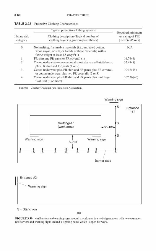
3.60 CHAPTER THREE
TABLE 3.22 Protective Clothing Characteristics
Typical protective clothing systemsRequired minimum
Hazard risk Clothing description (Typical number of arc rating of PPEcategory clothing layers is given in parentheses) [J/cm2(cal/cm2)]
0 Nonmelting, flammable materials (i.e., untreated cotton, N/Awool, rayon, or silk, or blends of these materials) with a fabric weight at least 4.5 oz/yd2(1)
1 FR shirt and FR pants or FR coverall (1) 16.74(4)2 Cotton underwear—conventional short sleeve and brief/shorts, 33.47(8)
plus FR shirt and FR pants (1 or 2)3 Cotton underwear plus FR shirt and FR pants plus FR coverall, 104.6(25)
or cotton underwear plus two FR coveralls (2 or 3)4 Cotton underwear plus FR shirt and FR pants plus multilayer 167.36(40)
flash suit (3 or more)
Source: Courtesy National Fire Protection Association.
Switchgear(work area)
Warning sign
Warning sign
Warning sign
Warning sign
Entrance#1
Entrance #2
Barrier tape
S S S S S S S S S
S
S
S
5′–10′
5′–10′
S = Stanchion(a)
FIGURE 3.30 (a) Barriers and warning signs around a work area in a switchgear room with two entrances.(b) Barriers and warning signs around a lighting panel which is open for work.
Figure 3.30b shows a similar barrier system for a hallway lighting panel. The clearancedistance here is less because of the need to allow passage down the hallway. Warning signsare used to alert personnel to the hazard.
Illumination
Personnel must not reach into or work in areas which do not have adequate illumination.Although de-energization is the preferred method of eliminating electrical hazards, if de-energization also eliminates illumination, alternative safety measures must be employed.
Conductive Clothing and Materials
When working on or around energized conductors, personnel should remove (preferred)and/or use insulating tape to wrap watches, rings, keys, knives, necklaces, and other suchconductive items they have on their bodies.
Conductive materials such as wire, tools, and ladders should be handled in such a way thatthey do not come into contact with energized conductors. If such material cannot be kept at asafe clearance distance (see section on Approach Distances), they should be wrapped or insu-lated. Metal ladders should never be used in electrical installations.
SAFETY PROCEDURES AND METHODS 3.61
FIGURE 3.30 (Continued)
Warningsign
Lighting panel
Barrier tape
S S S S S
S
S
3′–5′
S = Stanchion(b)
S
SWarning
sign
Hallway
3.62 CHAPTER THREE
Confined Work Spaces
A complete coverage of confined work spaces is beyond the scope of this handbook.Electrical safety hazards in confined work spaces should be avoided. The following stepsshould be employed:
1. If safe approach distances cannot be maintained, energized conductors should be cov-ered or barricaded so personnel cannot contact them.
2. Doors, hatches, and swinging panels should be secured so that they cannot swing openand push personnel into energized conductors.
3. Confined work spaces should be well ventilated to prevent the concentration of gasesthat may explode in the presence of an electric arc.
4. Exits should be clearly marked. Employees should be familiarized with the exits beforeentering the confined work space.
5. Confined work spaces must be well illuminated so that all hazards are clearly visible.
TOOLS AND TEST EQUIPMENT
General
Many electrical accidents involve failures of electric tools or test equipment. Such failurestake a number of different forms including insulation failure, open ground return wires, inter-nal shorts to ground, and overheating. These problems can be aggravated or even caused byusing tools or test equipment improperly. For example, if extension cords not designed for usein wet areas are used in standing water, severe electric shock can result. The following gen-eral procedures should be employed when using electric tools or test equipment:
1. Tools and test equipment should be closely inspected before each use. (See section onVisual Inspection.)
2. Cord-connected tools should never be lifted or handled by their power cord. If toolsmust be lifted, a rope should be attached.
3. Grounded tools and equipment must have a continuous metallic connection from thetool ground to the supply ground.
4. If a grounded supply system is not available, double-insulated tools should be used.
5. Three-wire connection plugs should never be altered to fit into two-wire sockets.
6. So-called cheater plugs should not be used unless the third wire of the plug can besecurely connected to the supply ground.
7. Locking types of plugs should be securely locked before the tool is energized.
8. Cords and tools should not be used in a wet environment unless they are specificallydesigned for such an application.
Authorized Users
Only authorized, trained persons should be allowed to use electric tools and test equipment.The training should include all the necessary inspection techniques for the tools that will beemployed, plus recognition of the common types of safety hazards that are peculiar to thetool being used.
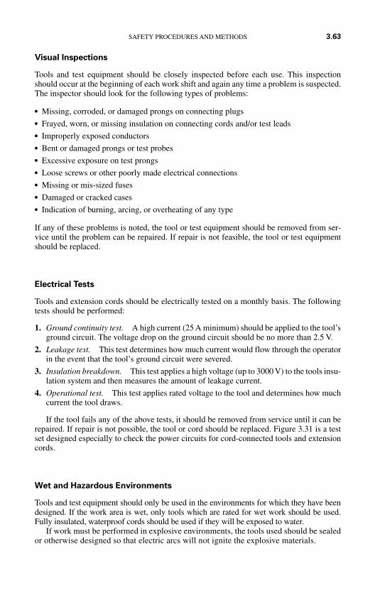
Visual Inspections
Tools and test equipment should be closely inspected before each use. This inspectionshould occur at the beginning of each work shift and again any time a problem is suspected.The inspector should look for the following types of problems:
Missing, corroded, or damaged prongs on connecting plugs Frayed, worn, or missing insulation on connecting cords and/or test leads Improperly exposed conductors Bent or damaged prongs or test probes Excessive exposure on test prongs Loose screws or other poorly made electrical connections Missing or mis-sized fuses Damaged or cracked cases Indication of burning, arcing, or overheating of any type
If any of these problems is noted, the tool or test equipment should be removed from ser-vice until the problem can be repaired. If repair is not feasible, the tool or test equipmentshould be replaced.
Electrical Tests
Tools and extension cords should be electrically tested on a monthly basis. The followingtests should be performed:
1. Ground continuity test. A high current (25 A minimum) should be applied to the tool’sground circuit. The voltage drop on the ground circuit should be no more than 2.5 V.
2. Leakage test. This test determines how much current would flow through the operatorin the event that the tool’s ground circuit were severed.
3. Insulation breakdown. This test applies a high voltage (up to 3000 V) to the tools insu-lation system and then measures the amount of leakage current.
4. Operational test. This test applies rated voltage to the tool and determines how muchcurrent the tool draws.
If the tool fails any of the above tests, it should be removed from service until it can berepaired. If repair is not possible, the tool or cord should be replaced. Figure 3.31 is a testset designed especially to check the power circuits for cord-connected tools and extensioncords.
Wet and Hazardous Environments
Tools and test equipment should only be used in the environments for which they have beendesigned. If the work area is wet, only tools which are rated for wet work should be used.Fully insulated, waterproof cords should be used if they will be exposed to water.
If work must be performed in explosive environments, the tools used should be sealedor otherwise designed so that electric arcs will not ignite the explosive materials.
SAFETY PROCEDURES AND METHODS 3.63
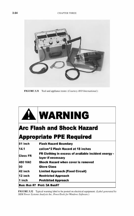
3.64 CHAPTER THREE
FIGURE 3.31 Tool and appliance tester. (Courtesy AVO International.)
FIGURE 3.32 Typical warning label to be posted on electrical equipment. (Label generated bySKM Power Systems Analysis Inc, PowerTools for Windows Software.)
FIELD MARKING OF POTENTIAL HAZARDS
The type and degree of hazard determined by the various procedures outlined in this chap-ter should be clearly posted at each piece of electrical equipment in the field. These warn-ing labels should clearly identify the type and degree of the hazard and should include thetype and amount of PPE required to work in, on, or around the equipment. Figure 3.32 isan example of such a label.
Warning labels of this type should be placed on switchboards, panelboards, industrial-control panels, metalclad switchgear, meter-socket enclosures, motor-control centers,transformers, motors, generators, and all other such equipment where employees may beexposed to one of the electrical hazards.
Some equipment may have more than one such label. For example, the primary of atransformer may have a different arc-energy level than the secondary. Depending on themechanical configuration, a label may be required for the primary feeder section of thetransformer and the secondary transition cabinet into the switchgear that it feeds.
THE ONE-MINUTE SAFETY AUDIT
Inattention is one of the major root causes of all accidents. Employees whose attention isdistracted by work-related or personal problems are prone to miss obvious signs of impend-ing hazards. To make certain that employees are constantly aware of potential hazards, thesteps listed in Table 3.23 should be performed by each worker that enters an area where anyof the electrical hazards may be present.
The following nine simple steps should not take more than 1 min to perform, even in avery large electrical facility. Of course, not every step will apply in each and every situa-tion. For example, some electrical rooms have no transformers; therefore, step 5 would notbe performed.
1. Notify responsible personnel of your presence in the area. In the event that a problemdoes occur you may not be able to summon the help that you need. If other personnelare aware of your presence in the area, they will know to come to your aid.
2. Listen for any abnormally loud or unusual noises. Sniff for unusual odors. Transformersand other electric equipment do make noise during normal operation. When such noisesbecome too loud or change tone, trouble may be indicated. Burning odors or the smellof ozone can also be signs of incipient faults.
SAFETY PROCEDURES AND METHODS 3.65
1. Notify responsible personnel of your presence in the area.2. Listen for any abnormally loud or unusual noises. Sniff for unusual odors.3. Locate all emergency exits.4. Locate all fire alarms and telephones.5. Inspect all transformer liquid level, temperature, and pressure gauges to make certain that they are
within acceptable limits.6. Locate the station one-line diagram and make certain that it is legible and correct.7. Make certain that the room is neat and tidy. Generally, electrical facilities should not be used for
the storage of equipment.8. Be certain that all required safety equipment is readily available and easily reached.9. Check to see that all protective relay and other operational flags are properly reset.
TABLE 3.23 The One-Minute Safety Audit
3. Locate all emergency exits. Electrical accidents are often accompanied by smoke, fire,and noise. Such conditions make it difficult or impossible to find the exits. If exit loca-tions are committed to memory before any problems occur, the worker is more likely toremember them after the problem occurs.
4. Locate all fire alarms and telephones. The same reasoning applies here as locating emergencyexits. During an emergency the location of fire alarms and telephones should be a reflex.
5. Inspect all transformer gauges. Transformers will often warn of impending failures byan increase in pressure, temperature, liquid level, or some combination of all these. Aninspection of these elements can warn of a problem before it happens.
6. Locate the station one-line diagram. Switching and other such activities must be carriedout in a safe manner. To do so requires that the system one-line diagram be accurate. Fewthings are more hazardous than opening a switch which is believed to be the source to anenergized part of the system and then finding out later that, in fact, it was the wrong switch.
7. Make certain that the room is clean and tidy. Storage of some equipment in an electricalfacility is a necessary and valuable procedure. For example, what better place to storeelectrical safety equipment than close to the gear where it may be needed. Ladders, tools,hot sticks, rubber insulating goods, replacement lights, and other such materials are allcandidates for storage in the electrical facility. When such storage does take place, how-ever, it should be done in an orderly and safe fashion. Storage cabinets should be pro-cured for small equipment. Ladders should be hung on racks especially mounted for sucha purpose. Wire reels and other such materials should not be in the exit paths.
8. Be certain that all safety equipment is readily available. Workers will often use the excusethat “the safety gear is too far away to justify using it for this short procedure.” To eliminatesuch an excuse, the safety equipment should be readily available. Whether it is brought inwith the work crew or stored in the electrical facility, it must be readily available.
9. Check all protective relay flags and other indicators. Operation indicators can oftenbe a precursor of a safety problem. A pressure alarm that will not reset, for example,can indicate an impending explosion. Such indicators should be checked. Such anindicator should never be reset without first determining what caused the problem.Also, operations personnel should be contacted before resetting.
These nine simple steps can be quickly accomplished by all personnel . . . and they maysave a life.
REFERENCES
1. A.M. Stoll, and M.A. Chianta, “Method and Rating system for Evaluation of Thermal Protection,”Aerospace Medicine, 40: pp.1232–1238, 1968.
2. Richard L. Doughty, Thomas E. Neal, and H. Landis Floyd, “Predicting Incident Energy to BetterManage the Electric Arc Hazard on 600-V Power Distrbution Systems,” IEEE Paper.
3. Institute of Electrical and Electronic Engineers (IEEE), “IEEE Guide for Performing Arc-FlashCalculations,” IEEE Std 1584-2002, Piscataway, NJ.
3.66 CHAPTER THREE
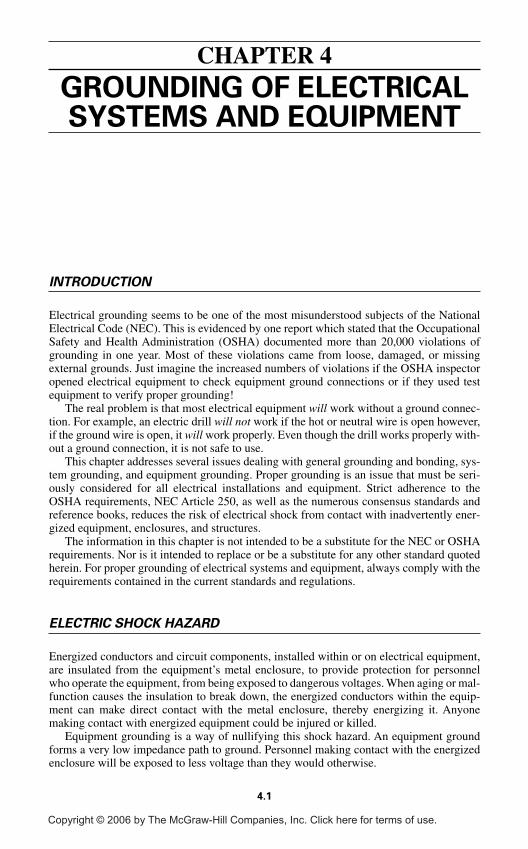
GROUNDING OF ELECTRICALSYSTEMS AND EQUIPMENT
INTRODUCTION
Electrical grounding seems to be one of the most misunderstood subjects of the NationalElectrical Code (NEC). This is evidenced by one report which stated that the OccupationalSafety and Health Administration (OSHA) documented more than 20,000 violations ofgrounding in one year. Most of these violations came from loose, damaged, or missingexternal grounds. Just imagine the increased numbers of violations if the OSHA inspectoropened electrical equipment to check equipment ground connections or if they used testequipment to verify proper grounding!
The real problem is that most electrical equipment will work without a ground connec-tion. For example, an electric drill will not work if the hot or neutral wire is open however,if the ground wire is open, it will work properly. Even though the drill works properly with-out a ground connection, it is not safe to use.
This chapter addresses several issues dealing with general grounding and bonding, sys-tem grounding, and equipment grounding. Proper grounding is an issue that must be seri-ously considered for all electrical installations and equipment. Strict adherence to theOSHA requirements, NEC Article 250, as well as the numerous consensus standards andreference books, reduces the risk of electrical shock from contact with inadvertently ener-gized equipment, enclosures, and structures.
The information in this chapter is not intended to be a substitute for the NEC or OSHArequirements. Nor is it intended to replace or be a substitute for any other standard quotedherein. For proper grounding of electrical systems and equipment, always comply with therequirements contained in the current standards and regulations.
ELECTRIC SHOCK HAZARD
Energized conductors and circuit components, installed within or on electrical equipment,are insulated from the equipment’s metal enclosure, to provide protection for personnelwho operate the equipment, from being exposed to dangerous voltages. When aging or mal-function causes the insulation to break down, the energized conductors within the equip-ment can make direct contact with the metal enclosure, thereby energizing it. Anyonemaking contact with energized equipment could be injured or killed.
Equipment grounding is a way of nullifying this shock hazard. An equipment groundforms a very low impedance path to ground. Personnel making contact with the energizedenclosure will be exposed to less voltage than they would otherwise.
4.1
CHAPTER 4
Copyright © 2006 by The McGraw-Hill Companies, Inc. Click here for terms of use.
4.2 CHAPTER FOUR
Simply stated, proper bonding and grounding of electrical equipment will substantiallyreduce the risk of electrical shock by effectively eliminating a difference in potential.
GENERAL REQUIREMENTS FOR GROUNDINGAND BONDING
Definitions
The following terms are defined here due to their frequent use in this chapter. The definitionscontained in this chapter are taken verbatim from OSHA 29 CFR 1910.399. Correspondingdefinitions can also be found in Article 100 of the current edition of the NEC.
Bonding (Bonded). The permanent joining of metallic parts to form an electrically con-ductive path that will ensure electrical continuity and the capacity to conduct safely any cur-rent likely to be imposed.
Bonding Jumper. A reliable conductor to ensure the required electrical conductivitybetween metal parts required to be electrically connected.
Bonding Jumper, Equipment. The connection between two or more portions of theequipment grounding conductor.
Bonding Jumper, Main. The connection between the grounded circuit conductor and theequipment grounding conductor at the service.
Energized. Electrically connected to a source of potential difference.
Equipment. A general term including material, fittings, devices, appliances, fixtures,apparatus, and the like used as a part of, or in connection with, an electrical installation.
Ground. A conducting connection, whether intentional or accidental, between an electri-cal circuit or equipment and the earth, or to some conducting body that serves in place ofthe earth.
Grounded. Connected to earth or to some conducting body that serves in place of theearth.
Grounded, Effectively. Intentionally connected to earth through a ground connection orconnections of sufficiently low impedance and having sufficient current-carrying capacityto prevent the buildup of voltages that may result in undue hazards to connected equipmentor to persons.
Grounding Conductor. A conductor used to connect equipment or the grounded circuitof a wiring system to a grounding electrode or electrodes.
Grounding Conductor, Equipment. The conductor used to connect the non-current-carrying metal parts of equipment, raceways, and other enclosures to the system groundedconductor, the grounding electrode conductor, or both, at the service equipment or at thesource of a separately derived system.
Grounding Electrode Conductor. The conductor used to connect the grounding elec-trode to the equipment grounding conductor, to the grounded conductor, or to both, of thecircuit at the service equipment or at the source of a separately derived system.
Grounding Electrode System. Two or more grounding electrodes that are effectivelybonded together shall be considered a single grounding electrode system.
Ground-Fault Circuit Interrupter. A device intended for the protection of personnel thatfunctions to de-energize a circuit or portion thereof within an established period of timewhen a current to ground exceeds some predetermined value that is less than that requiredto operate the overcurrent protective device of the supply circuit.
Ground-Fault Protection of Equipment. A system intended to provide protection ofequipment from damaging line-to-ground fault currents by operating to cause a discon-necting means to open all ungrounded conductors of the faulted circuit. This protection isprovided at current levels less than those required to protect conductors from damagethrough the operation of a supply circuit overcurrent device.
Grounding of Electrical Systems
Grounded electrical systems are required to be connected to earth in such a way as to limitany voltages imposed by lightning, line surges, or unintentional contact with higher volt-age lines. Electrical systems are also grounded to stabilize the voltage to earth during nor-mal operation. If, for example, the neutral of a 120/240 V, wye-connected secondary of atransformer were not grounded, instead of being 120 V to ground, the voltage could reachseveral hundred volts to ground. A wye-connected electrical system becomes very unstableif it is not properly grounded.
The following requirements are taken from OSHA 29 CFR 1910.304(f) and can also befound in the 2005 National Electrical Code (NEC)® Section 250.20.
(f) Grounding. Paragraphs (f)(1) through (f)(7) of this section contain groundingrequirements for systems, circuits, and equipment.
(1) Systems to be grounded. The following systems, which supply premises wiring,shall be grounded:
(i) All 3-wire DC systems shall have their neutral conductor grounded.
(ii) Two-wire DC systems operating at over 50 volts through 300 volts between con-ductors shall be grounded unless:
(A) They supply only industrial equipment in limited areas and are equipped with aground detector; or
(B) They are rectifier-derived from an AC system complying with paragraphs (f)(1)(iii),(f)(1)(iv), and (f)(1)(v) of this section; or
(C) They are fire-protective signaling circuits having a maximum current of 0.030amperes.
(iii) AC circuits of less than 50 volts shall be grounded if they are installed as overheadconductors outside of buildings or if they are supplied by transformers and the trans-former primary supply system is ungrounded or exceeds 150 volts to ground.
(iv) AC systems of 50 volts to 1000 volts shall be grounded under any of the followingconditions, unless exempted by paragraph (f)(1)(v) of this section:
(A) If the system can be so grounded that the maximum voltage to ground on theungrounded conductors does not exceed 150 volts; (see Fig. 4.1)
GROUNDING OF ELECTRICAL SYSTEMS AND EQUIPMENT 4.3
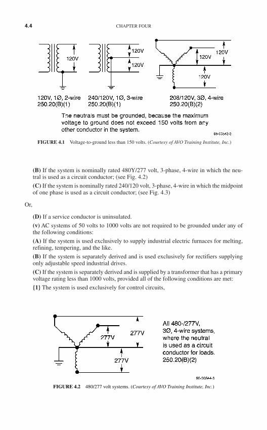
(B) If the system is nominally rated 480Y/277 volt, 3-phase, 4-wire in which the neu-tral is used as a circuit conductor; (see Fig. 4.2)
(C) If the system is nominally rated 240/120 volt, 3-phase, 4-wire in which the midpointof one phase is used as a circuit conductor; (see Fig. 4.3)
Or,
(D) If a service conductor is uninsulated.
(v) AC systems of 50 volts to 1000 volts are not required to be grounded under any ofthe following conditions:
(A) If the system is used exclusively to supply industrial electric furnaces for melting,refining, tempering, and the like.
(B) If the system is separately derived and is used exclusively for rectifiers supplyingonly adjustable speed industrial drives.
(C) If the system is separately derived and is supplied by a transformer that has a primaryvoltage rating less than 1000 volts, provided all of the following conditions are met:
1 The system is used exclusively for control circuits,
4.4 CHAPTER FOUR
FIGURE 4.1 Voltage-to-ground less than 150 volts. (Courtesy of AVO Training Institute, Inc.)
FIGURE 4.2 480/277 volt systems. (Courtesy of AVO Training Institute, Inc.)
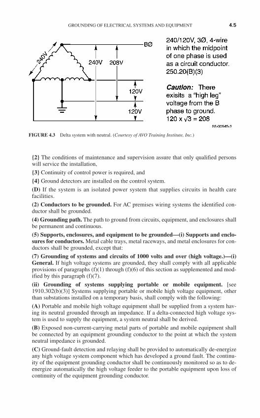
2 The conditions of maintenance and supervision assure that only qualified personswill service the installation,
3 Continuity of control power is required, and
4 Ground detectors are installed on the control system.
(D) If the system is an isolated power system that supplies circuits in health carefacilities.
(2) Conductors to be grounded. For AC premises wiring systems the identified con-ductor shall be grounded.
(4) Grounding path. The path to ground from circuits, equipment, and enclosures shallbe permanent and continuous.
(5) Supports, enclosures, and equipment to be grounded—(i) Supports and enclo-sures for conductors. Metal cable trays, metal raceways, and metal enclosures for con-ductors shall be grounded, except that:
(7) Grounding of systems and circuits of 1000 volts and over (high voltage.)—(i)General. If high voltage systems are grounded, they shall comply with all applicableprovisions of paragraphs (f)(1) through (f)(6) of this section as supplemented and mod-ified by this paragraph (f)(7).
(ii) Grounding of systems supplying portable or mobile equipment. [see1910.302(b)(3)] Systems supplying portable or mobile high voltage equipment, otherthan substations installed on a temporary basis, shall comply with the following:
(A) Portable and mobile high voltage equipment shall be supplied from a system hav-ing its neutral grounded through an impedance. If a delta-connected high voltage sys-tem is used to supply the equipment, a system neutral shall be derived.
(B) Exposed non-current-carrying metal parts of portable and mobile equipment shallbe connected by an equipment grounding conductor to the point at which the systemneutral impedance is grounded.
(C) Ground-fault detection and relaying shall be provided to automatically de-energizeany high voltage system component which has developed a ground fault. The continu-ity of the equipment grounding conductor shall be continuously monitored so as to de-energize automatically the high voltage feeder to the portable equipment upon loss ofcontinuity of the equipment grounding conductor.
GROUNDING OF ELECTRICAL SYSTEMS AND EQUIPMENT 4.5
FIGURE 4.3 Delta system with neutral. (Courtesy of AVO Training Institute, Inc.)
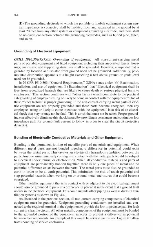
(D) The grounding electrode to which the portable or mobile equipment system neu-tral impedance is connected shall be isolated from and separated in the ground by atleast 20 feet from any other system or equipment grounding electrode, and there shallbe no direct connection between the grounding electrodes, such as buried pipe, fence,and so on.
Grounding of Electrical Equipment
OSHA 1910.304(f)(7)(iii) Grounding of equipment. All non-current-carrying metalparts of portable equipment and fixed equipment including their associated fences, hous-ings, enclosures, and supporting structures shall be grounded. However, equipment that isguarded by location and isolated from ground need not be grounded. Additionally, pole-mounted distribution apparatus at a height exceeding 8 feet above ground or grade levelneed not be grounded.
In 29 CFR 1910.303, “General Requirements,” OSHA states under “(b) Examination,installation, and use of equipment (1) Examination” that “Electrical equipment shall befree from recognized hazards that are likely to cause death or serious physical harm toemployees.” This section continues with “other factors which contribute to the practicalsafeguarding of employees using or likely to come in contact with the equipment.” One ofthese “other factors” is proper grounding. If the non-current-carrying metal parts of elec-tric equipment are not properly grounded and these parts become energized, then anyemployee “using or likely to come in contact with the equipment” is at risk of an electri-cal shock that may or may not be fatal. This is a risk that must not be taken. Proper ground-ing can effectively eliminate this shock hazard by providing a permanent and continuous lowimpedance path for ground-fault current to follow in order to clear the circuit protectivedevice(s).
Bonding of Electrically Conductive Materials and Other Equipment
Bonding is the permanent joining of metallic parts of materials and equipment. Whendifferent metal parts are not bonded together, a difference in potential could existbetween the metal parts. This creates an electrically hazardous condition between theparts. Anyone simultaneously coming into contact with the metal parts would be subjectto electrical shock, burns, or electrocution. When all conductive materials and parts ofequipment are permanently bonded together, there is only one piece of metal and nopotential difference exists between the parts. The metal parts must also be grounded toearth in order to be at earth potential. This minimizes the risk of touch-potential andstep-potential hazards when working on or around metal enclosures that could becomeenergized.
Other metallic equipment that is in contact with or adjacent to the electrical equipmentshould also be grounded to prevent a difference in potential in the event that a ground faultoccurs in the electrical equipment. This could include other piping as well as ducts in ven-tilation systems as shown in Fig. 4.4.
As discussed in the previous section, all non-current-carrying components of electricalequipment must be grounded. Equipment grounding conductors are installed and con-nected to the required terminal in the equipment to provide the low impedance path for faultcurrent to clear the circuit. All other metallic components of the equipment must be bondedto the grounded portion of the equipment in order to prevent a difference in potentialbetween the components. An example of this would be service enclosures. Figure 4.5 illus-trates bonding of service enclosures.
4.6 CHAPTER FOUR
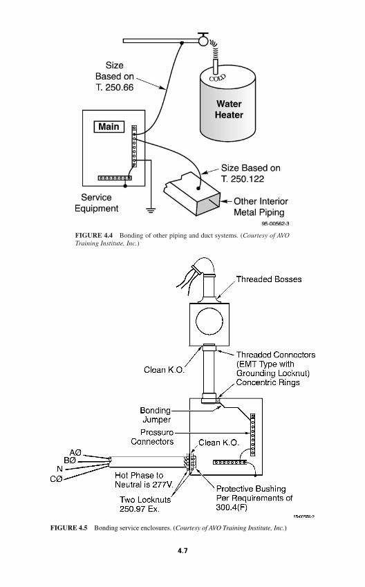
FIGURE 4.4 Bonding of other piping and duct systems. (Courtesy of AVOTraining Institute, Inc.)
FIGURE 4.5 Bonding service enclosures. (Courtesy of AVO Training Institute, Inc.)
4.7
Performance of Fault Path
OSHA makes a very simple statement on the performance of the fault path as found in1910.304(f)(4) which states: “Grounding path. The path to ground from circuits, equip-ment, and enclosures shall be permanent and continuous.” NEC Section 250.4(A)(5) alsorequires the fault current path to be able to safely carry the maximum ground-fault cur-rent, provide a low impedance path in order to clear the overcurrent devices, and performin a way that the earth is not used as the sole equipment grounding conductor for faultcurrent.
The fault current path must meet these criteria in order for the overcurrent protection toclear the circuit in the event a ground fault occurs. A low-impedance conductor path mustbe used because the earth provides an extremely high impedance path and would not allowa sufficient amount of fault current to flow to clear the overcurrent device. Another factoris that a low-impedance conductor path for fault current to flow through minimizes the pos-sibility of step- and touch-potential hazards by limiting the voltage to ground.
Arrangement to Prevent Objectionable Current
Grounding of electrical equipment and systems must be accomplished in a manner thatwould prevent objectionable current. The main point here is to install an effective ground-ing system without creating an objectionable current situation. Circulating current is oneform of objectionable current that can occur when multiple grounds are utilized.
Alterations to Stop Objectionable Current
Objectionable current flow can occur when using multiple grounds in electrical systemsand equipment. If this occurs there are several different options to prevent or at least mini-mize this current flow:
1. One or more of the grounds may be discontinued. Never discontinue all of the grounds.
2. The grounding connection may be changed to another location.
3. The conductive path for the grounding connections may be interrupted.
4. The authority having jurisdiction may grant other remedial action.
Temporary Currents Not Classified as Objectionable Current
One thing to keep in mind when dealing with this subject is that there are times when cur-rent will flow in the grounding system or through the non-current carrying parts of electri-cal equipment. Ground faults in equipment do occur and that is when the grounding systemperforms its function. These currents are not classified as objectionable current for the pur-pose of this discussion.
Connection of Grounding and Bonding Equipment
Conductors for grounding and bonding of electrical equipment must be connected using anapproved method such as exothermic welding, listed pressure connections, listed clamps,
4.8 CHAPTER FOUR
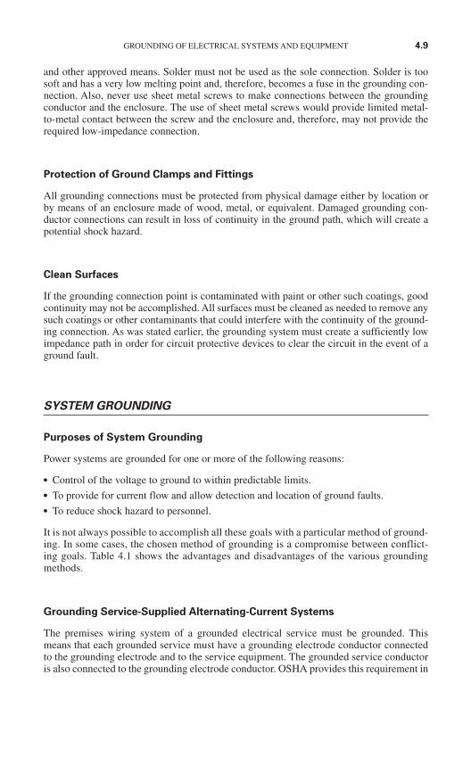
and other approved means. Solder must not be used as the sole connection. Solder is toosoft and has a very low melting point and, therefore, becomes a fuse in the grounding con-nection. Also, never use sheet metal screws to make connections between the groundingconductor and the enclosure. The use of sheet metal screws would provide limited metal-to-metal contact between the screw and the enclosure and, therefore, may not provide therequired low-impedance connection.
Protection of Ground Clamps and Fittings
All grounding connections must be protected from physical damage either by location orby means of an enclosure made of wood, metal, or equivalent. Damaged grounding con-ductor connections can result in loss of continuity in the ground path, which will create apotential shock hazard.
Clean Surfaces
If the grounding connection point is contaminated with paint or other such coatings, goodcontinuity may not be accomplished. All surfaces must be cleaned as needed to remove anysuch coatings or other contaminants that could interfere with the continuity of the ground-ing connection. As was stated earlier, the grounding system must create a sufficiently lowimpedance path in order for circuit protective devices to clear the circuit in the event of aground fault.
SYSTEM GROUNDING
Purposes of System Grounding
Power systems are grounded for one or more of the following reasons:
Control of the voltage to ground to within predictable limits. To provide for current flow and allow detection and location of ground faults. To reduce shock hazard to personnel.
It is not always possible to accomplish all these goals with a particular method of ground-ing. In some cases, the chosen method of grounding is a compromise between conflict-ing goals. Table 4.1 shows the advantages and disadvantages of the various groundingmethods.
Grounding Service-Supplied Alternating-Current Systems
The premises wiring system of a grounded electrical service must be grounded. Thismeans that each grounded service must have a grounding electrode conductor connectedto the grounding electrode and to the service equipment. The grounded service conductoris also connected to the grounding electrode conductor. OSHA provides this requirement in
GROUNDING OF ELECTRICAL SYSTEMS AND EQUIPMENT 4.9
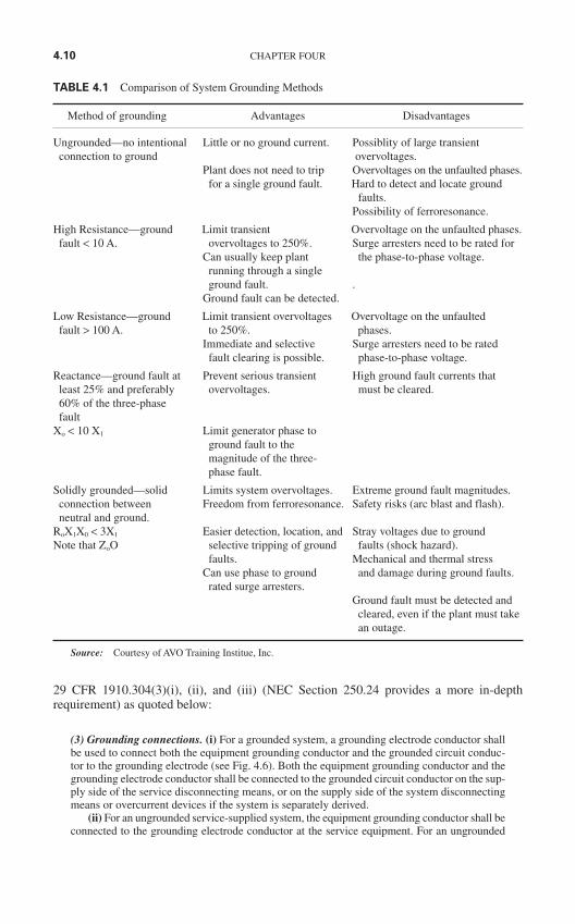
29 CFR 1910.304(3)(i), (ii), and (iii) (NEC Section 250.24 provides a more in-depthrequirement) as quoted below:
(3) Grounding connections. (i) For a grounded system, a grounding electrode conductor shallbe used to connect both the equipment grounding conductor and the grounded circuit conduc-tor to the grounding electrode (see Fig. 4.6). Both the equipment grounding conductor and thegrounding electrode conductor shall be connected to the grounded circuit conductor on the sup-ply side of the service disconnecting means, or on the supply side of the system disconnectingmeans or overcurrent devices if the system is separately derived.
(ii) For an ungrounded service-supplied system, the equipment grounding conductor shall beconnected to the grounding electrode conductor at the service equipment. For an ungrounded
4.10 CHAPTER FOUR
TABLE 4.1 Comparison of System Grounding Methods
Method of grounding Advantages Disadvantages
Ungrounded—no intentional Little or no ground current. Possiblity of large transientconnection to ground overvoltages.
Plant does not need to trip Overvoltages on the unfaulted phases.for a single ground fault. Hard to detect and locate ground
faults.Possibility of ferroresonance.
High Resistance—ground Limit transient Overvoltage on the unfaulted phases.fault < 10 A. overvoltages to 250%. Surge arresters need to be rated for
Can usually keep plant the phase-to-phase voltage.running through a single ground fault. .
Ground fault can be detected.
Low Resistance—ground Limit transient overvoltages Overvoltage on the unfaultedfault > 100 A. to 250%. phases.
Immediate and selective Surge arresters need to be ratedfault clearing is possible. phase-to-phase voltage.
Reactance—ground fault at Prevent serious transient High ground fault currents that least 25% and preferably overvoltages. must be cleared.60% of the three-phase fault
Xo < 10 X1 Limit generator phase toground fault to themagnitude of the three-phase fault.
Solidly grounded—solid Limits system overvoltages. Extreme ground fault magnitudes.connection between Freedom from ferroresonance. Safety risks (arc blast and flash).neutral and ground.
RoX1X0 < 3X1 Easier detection, location, and Stray voltages due to groundNote that ZoO selective tripping of ground faults (shock hazard).
faults. Mechanical and thermal stressCan use phase to ground and damage during ground faults.
rated surge arresters.Ground fault must be detected and
cleared, even if the plant must takean outage.
Source: Courtesy of AVO Training Institue, Inc.
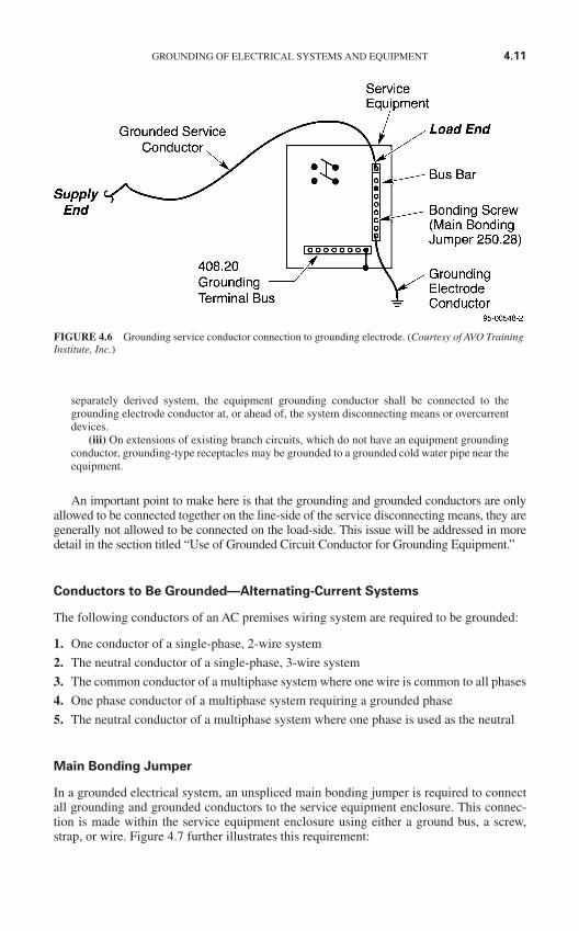
separately derived system, the equipment grounding conductor shall be connected to thegrounding electrode conductor at, or ahead of, the system disconnecting means or overcurrentdevices.
(iii) On extensions of existing branch circuits, which do not have an equipment groundingconductor, grounding-type receptacles may be grounded to a grounded cold water pipe near theequipment.
An important point to make here is that the grounding and grounded conductors are onlyallowed to be connected together on the line-side of the service disconnecting means, they aregenerally not allowed to be connected on the load-side. This issue will be addressed in moredetail in the section titled “Use of Grounded Circuit Conductor for Grounding Equipment.”
Conductors to Be Grounded—Alternating-Current Systems
The following conductors of an AC premises wiring system are required to be grounded:
1. One conductor of a single-phase, 2-wire system
2. The neutral conductor of a single-phase, 3-wire system
3. The common conductor of a multiphase system where one wire is common to all phases
4. One phase conductor of a multiphase system requiring a grounded phase
5. The neutral conductor of a multiphase system where one phase is used as the neutral
Main Bonding Jumper
In a grounded electrical system, an unspliced main bonding jumper is required to connectall grounding and grounded conductors to the service equipment enclosure. This connec-tion is made within the service equipment enclosure using either a ground bus, a screw,strap, or wire. Figure 4.7 further illustrates this requirement:
GROUNDING OF ELECTRICAL SYSTEMS AND EQUIPMENT 4.11
FIGURE 4.6 Grounding service conductor connection to grounding electrode. (Courtesy of AVO TrainingInstitute, Inc.)
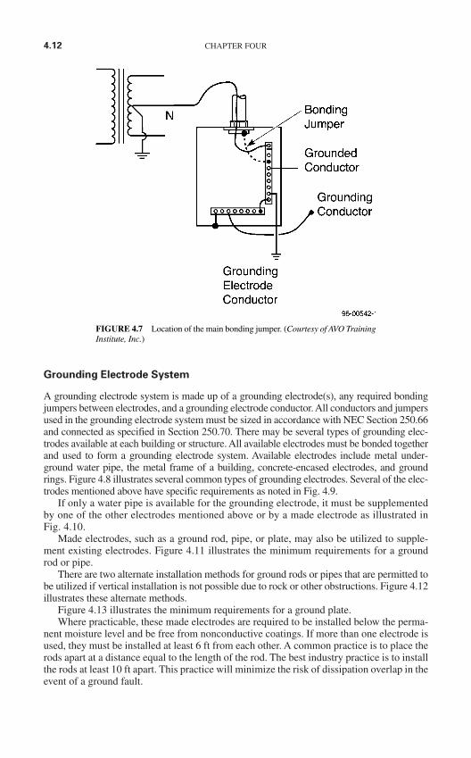
Grounding Electrode System
A grounding electrode system is made up of a grounding electrode(s), any required bondingjumpers between electrodes, and a grounding electrode conductor. All conductors and jumpersused in the grounding electrode system must be sized in accordance with NEC Section 250.66and connected as specified in Section 250.70. There may be several types of grounding elec-trodes available at each building or structure. All available electrodes must be bonded togetherand used to form a grounding electrode system. Available electrodes include metal under-ground water pipe, the metal frame of a building, concrete-encased electrodes, and groundrings. Figure 4.8 illustrates several common types of grounding electrodes. Several of the elec-trodes mentioned above have specific requirements as noted in Fig. 4.9.
If only a water pipe is available for the grounding electrode, it must be supplementedby one of the other electrodes mentioned above or by a made electrode as illustrated inFig. 4.10.
Made electrodes, such as a ground rod, pipe, or plate, may also be utilized to supple-ment existing electrodes. Figure 4.11 illustrates the minimum requirements for a groundrod or pipe.
There are two alternate installation methods for ground rods or pipes that are permitted tobe utilized if vertical installation is not possible due to rock or other obstructions. Figure 4.12illustrates these alternate methods.
Figure 4.13 illustrates the minimum requirements for a ground plate.Where practicable, these made electrodes are required to be installed below the perma-
nent moisture level and be free from nonconductive coatings. If more than one electrode isused, they must be installed at least 6 ft from each other. A common practice is to place therods apart at a distance equal to the length of the rod. The best industry practice is to installthe rods at least 10 ft apart. This practice will minimize the risk of dissipation overlap in theevent of a ground fault.
4.12 CHAPTER FOUR
FIGURE 4.7 Location of the main bonding jumper. (Courtesy of AVO TrainingInstitute, Inc.)
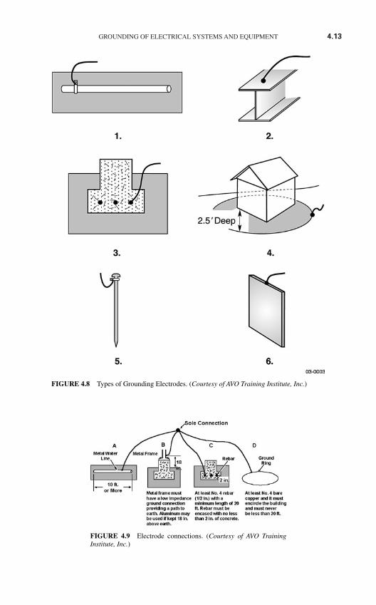
GROUNDING OF ELECTRICAL SYSTEMS AND EQUIPMENT 4.13
FIGURE 4.8 Types of Grounding Electrodes. (Courtesy of AVO Training Institute, Inc.)
FIGURE 4.9 Electrode connections. (Courtesy of AVO TrainingInstitute, Inc.)
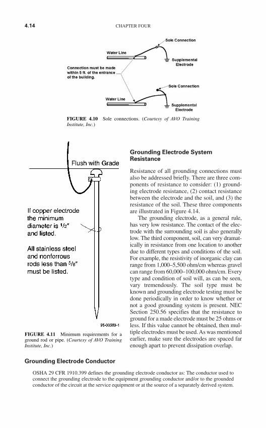
Grounding Electrode SystemResistance
Resistance of all grounding connections mustalso be addressed briefly. There are three com-ponents of resistance to consider: (1) ground-ing electrode resistance, (2) contact resistancebetween the electrode and the soil, and (3) theresistance of the soil. These three componentsare illustrated in Figure 4.14.
The grounding electrode, as a general rule,has very low resistance. The contact of the elec-trode with the surrounding soil is also generallylow. The third component, soil, can very dramat-ically in resistance from one location to anotherdue to different types and conditions of the soil.For example, the resistivity of inorganic clay canrange from 1,000–5,500 ohm/cm whereas gravelcan range from 60,000–100,000 ohm/cm. Everytype and condition of soil will, as can be seen,vary tremendously. The soil type must beknown and grounding electrode testing must bedone periodically in order to know whether ornot a good grounding system is present. NECSection 250.56 specifies that the resistance toground for a made electrode must be 25 ohms orless. If this value cannot be obtained, then mul-tiple electrodes must be used. As was mentionedearlier, make sure the electrodes are spaced farenough apart to prevent dissipation overlap.
Grounding Electrode Conductor
OSHA 29 CFR 1910.399 defines the grounding electrode conductor as: The conductor used toconnect the grounding electrode to the equipment grounding conductor and/or to the groundedconductor of the circuit at the service equipment or at the source of a separately derived system.
4.14 CHAPTER FOUR
FIGURE 4.10 Sole connections. (Courtesy of AVO TrainingInstitute, Inc.)
FIGURE 4.11 Minimum requirements for aground rod or pipe. (Courtesy of AVO TrainingInstitute, Inc.)
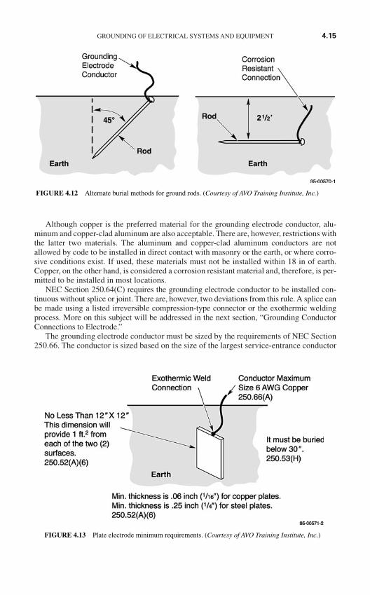
Although copper is the preferred material for the grounding electrode conductor, alu-minum and copper-clad aluminum are also acceptable. There are, however, restrictions withthe latter two materials. The aluminum and copper-clad aluminum conductors are notallowed by code to be installed in direct contact with masonry or the earth, or where corro-sive conditions exist. If used, these materials must not be installed within 18 in of earth.Copper, on the other hand, is considered a corrosion resistant material and, therefore, is per-mitted to be installed in most locations.
NEC Section 250.64(C) requires the grounding electrode conductor to be installed con-tinuous without splice or joint. There are, however, two deviations from this rule. A splice canbe made using a listed irreversible compression-type connector or the exothermic weldingprocess. More on this subject will be addressed in the next section, “Grounding ConductorConnections to Electrode.”
The grounding electrode conductor must be sized by the requirements of NEC Section250.66. The conductor is sized based on the size of the largest service-entrance conductor
GROUNDING OF ELECTRICAL SYSTEMS AND EQUIPMENT 4.15
FIGURE 4.12 Alternate burial methods for ground rods. (Courtesy of AVO Training Institute, Inc.)
FIGURE 4.13 Plate electrode minimum requirements. (Courtesy of AVO Training Institute, Inc.)
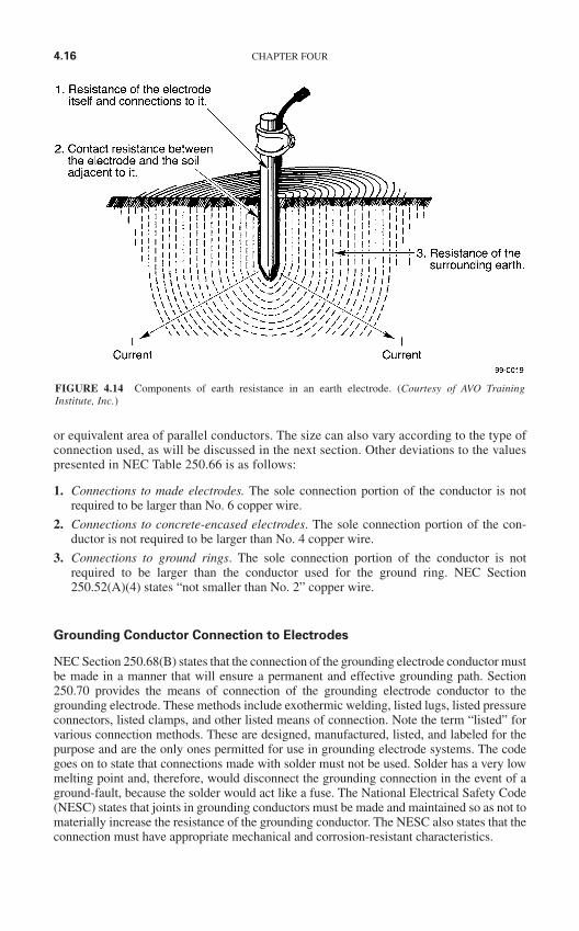
or equivalent area of parallel conductors. The size can also vary according to the type ofconnection used, as will be discussed in the next section. Other deviations to the valuespresented in NEC Table 250.66 is as follows:
1. Connections to made electrodes. The sole connection portion of the conductor is notrequired to be larger than No. 6 copper wire.
2. Connections to concrete-encased electrodes. The sole connection portion of the con-ductor is not required to be larger than No. 4 copper wire.
3. Connections to ground rings. The sole connection portion of the conductor is notrequired to be larger than the conductor used for the ground ring. NEC Section250.52(A)(4) states “not smaller than No. 2” copper wire.
Grounding Conductor Connection to Electrodes
NEC Section 250.68(B) states that the connection of the grounding electrode conductor mustbe made in a manner that will ensure a permanent and effective grounding path. Section250.70 provides the means of connection of the grounding electrode conductor to thegrounding electrode. These methods include exothermic welding, listed lugs, listed pressureconnectors, listed clamps, and other listed means of connection. Note the term “listed” forvarious connection methods. These are designed, manufactured, listed, and labeled for thepurpose and are the only ones permitted for use in grounding electrode systems. The codegoes on to state that connections made with solder must not be used. Solder has a very lowmelting point and, therefore, would disconnect the grounding connection in the event of aground-fault, because the solder would act like a fuse. The National Electrical Safety Code(NESC) states that joints in grounding conductors must be made and maintained so as not tomaterially increase the resistance of the grounding conductor. The NESC also states that theconnection must have appropriate mechanical and corrosion-resistant characteristics.
4.16 CHAPTER FOUR
FIGURE 4.14 Components of earth resistance in an earth electrode. (Courtesy of AVO TrainingInstitute, Inc.)
IEEE Std. 80, “Guide for Safety in AC Substation Grounding” is an excellent resourcefor determining the minimum size conductor based on the type of connection used. TheOnderdonk AC equation is used to calculate fusing current of a conductor based on the typeof connection used. Connectors and splice connections must also meet the requirements ofIEEE Std. 837 in order to be acceptable. The following examples will further illustrate thispoint:
For this example, a shortened version of the Onderdonk equation will be used to deter-mine conductor size and to determine fusing current levels based on the type of connection.
where A = Cable size, circular milK = Connector factorS = Maximum fault time, secondsI = Maximum fault current, amperes
For copper conductors these equations use the following “K” values to represent con-nection temperature:
Conductor only—1083°C temperature rating—value of “K” = 6.96 Welded connections—1083°C temperature rating—value of “K” = 6.96 Irreversible compression-type connections—1083°C temperature rating— value of “K” = 6.96 Brazed connections—450°C temperature rating—value of “K” = 9.12 Pressure-type connections—250°C temperature rating – value of “K” = 11.54
The following three examples, used to determine minimum conductor size, will use a20,000-A fault current with a protective device clearing time of 5 cycles (.083 second)using :
1. Pressure type connection:
A = 66,493 cm (minimum size conductor)
According to NEC Table 8, the size that corresponds to the minimum size conductorwould be a No. 1 AWG copper conductor (83,690 cm)
2. Brazed connection:
A = 52,549 cm (minimum size conductor)
According to NEC Table 8, the size that corresponds to the minimum size conductorwould be a No. 3 AWG copper conductor (52,620 cm)
3. Welded or irreversible compression-type connection:
A = 40,103 cm (minimum size conductor)
A 6.96 20,000= × × .083
A 9.12 20,000= × × .083
A = × ×11 54 20 000 083. , .
A KI S=
Conductor Size Fusing Current
A KI S IA
K S= =
GROUNDING OF ELECTRICAL SYSTEMS AND EQUIPMENT 4.17
According to NEC Table 8, the size that corresponds to the minimum size conductorwould be a No. 4 AWG copper conductor (41,740 cm)
As can be seen by the previous examples, if a pressure type connection were used, itwould require a conductor approximately 60 percent larger than a connection made with awelded or irreversible compression-type connection. The brazed connection would requirea conductor approximately 31 percent larger than a welded or irreversible compression-type connection. For practical purposes, the welded or irreversible compression-type con-nection would be the preferred choice.
Another consideration would be the approximate fusing current of the conductor basedon the type of connection. This example will use a 4/0 (211,600 cm) conductor with a pro-tective device clearing time of 5 cycles (.083 second) using .
1. Pressure type connection:
I = 63,646 amperes fusing current
2. Welded or irreversible compression-type connection:
I = 105,528 amperes fussing current
As can be seen in the above examples the conductor utilizing the welded or irreversiblecompression-type connection will handle much more current before fusing than the pressure-type connection.
When reliability and cost are taken into consideration, it is plain to see that the welded,as well as the irreversible compression-type, connection are far superior to any other typeof connection.
Bonding
If only one statement were to be made about grounding and bonding, it would be that all non-current-carrying parts of electrical equipment and nonelectrical equipment, likely to becomeenergized, be effectively grounded and bonded together. By using this general philosophy,there will be a minimum (near zero) risk that the non-current-carrying parts of equipment couldbecome energized. This would greatly reduce the risk of electrical shock or electrocution ofany person likely to come into contact with the equipment. As discussed earlier, a general state-ment in OSHA 29 CFR 1910.303(b)(1)(vii) includes, “other factors which contribute to thepractical safeguarding of employees using or likely to come in contact with the equipment.”One of these “other factors” refers to grounding and bonding of equipment likely to becomeenergized.
NEC Section 250.90 states that bonding must be provided where necessary to ensureelectrical continuity. Bonding is also required to ensure the capacity to safely conduct anyfault current that is likely to be imposed on the equipment. This requirement applies to alltypes of equipment, systems, and structures. NEC Article 250, Part V. Bonding, must becomplied with in order to size the bonding jumper correctly. Table 4.2 illustrates furtherwhy Part V must be adhered to.
I = 211600
6 96 083. .
I = 211600
11 54 083. .
I A K S= /
4.18 CHAPTER FOUR
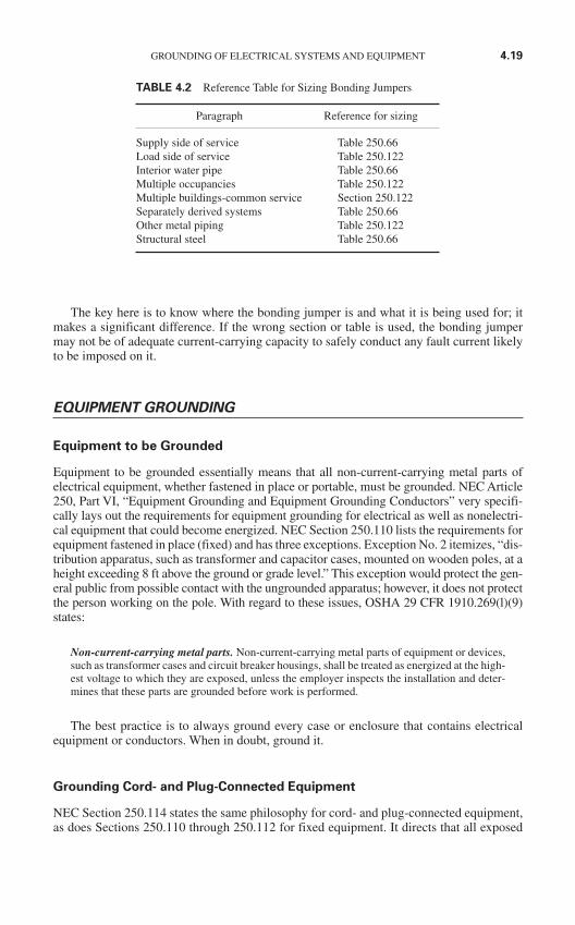
The key here is to know where the bonding jumper is and what it is being used for; itmakes a significant difference. If the wrong section or table is used, the bonding jumpermay not be of adequate current-carrying capacity to safely conduct any fault current likelyto be imposed on it.
EQUIPMENT GROUNDING
Equipment to be Grounded
Equipment to be grounded essentially means that all non-current-carrying metal parts ofelectrical equipment, whether fastened in place or portable, must be grounded. NEC Article250, Part VI, “Equipment Grounding and Equipment Grounding Conductors” very specifi-cally lays out the requirements for equipment grounding for electrical as well as nonelectri-cal equipment that could become energized. NEC Section 250.110 lists the requirements forequipment fastened in place (fixed) and has three exceptions. Exception No. 2 itemizes, “dis-tribution apparatus, such as transformer and capacitor cases, mounted on wooden poles, at aheight exceeding 8 ft above the ground or grade level.” This exception would protect the gen-eral public from possible contact with the ungrounded apparatus; however, it does not protectthe person working on the pole. With regard to these issues, OSHA 29 CFR 1910.269(l)(9)states:
Non-current-carrying metal parts. Non-current-carrying metal parts of equipment or devices,such as transformer cases and circuit breaker housings, shall be treated as energized at the high-est voltage to which they are exposed, unless the employer inspects the installation and deter-mines that these parts are grounded before work is performed.
The best practice is to always ground every case or enclosure that contains electricalequipment or conductors. When in doubt, ground it.
Grounding Cord- and Plug-Connected Equipment
NEC Section 250.114 states the same philosophy for cord- and plug-connected equipment,as does Sections 250.110 through 250.112 for fixed equipment. It directs that all exposed
GROUNDING OF ELECTRICAL SYSTEMS AND EQUIPMENT 4.19
TABLE 4.2 Reference Table for Sizing Bonding Jumpers
Paragraph Reference for sizing
Supply side of service Table 250.66Load side of service Table 250.122Interior water pipe Table 250.66Multiple occupancies Table 250.122Multiple buildings-common service Section 250.122Separately derived systems Table 250.66Other metal piping Table 250.122Structural steel Table 250.66
non-current-carrying metal parts that are likely to become energized must be grounded. Akey point here is “likely to become energized.” Any metal housing or enclosure that con-tains electrical components is, at some time or another, likely to become energized. Properequipment grounding techniques will provide the sufficiently low impedance path requiredto cause the overcurrent device to operate and clear the ground fault condition.
In the material written about electrical safety-related work practices, OSHA has pro-vided specific requirements for the use of portable electrical equipment and extensioncords. This requirement is found in OSHA 29 CFR 1910.334 where it states:
Use of equipment. (a) Portable electric equipment. (3) Grounding type equipment. (i) Aflexible cord used with grounding type equipment shall contain an equipment groundingconductor.
(ii) Attachment plugs and receptacles may not be connected or altered in a manner which wouldprevent proper continuity of the equipment grounding conductor at the point where plugs areattached to receptacles. Additionally, these devices may not be altered to allow the grounding poleof a plug to be inserted into slots intended for connection to the current-carrying conductors.
(iii) Adapters which interrupt the continuity of the equipment grounding connection may notbe used.
OSHA makes it very clear that this type of equipment must be grounded. Note as well thestatement in (iii) concerning adapters. The adapters referred to here are used when a groundedplug is required to be used where an ungrounded receptacle exists. These adapters are ULapproved and can be used, but only if used properly, that is, the ground connection must beattached to a return ground path. The problem with adapters is that the ground connectiondevice is generally cut off or otherwise not used, thus defeating the ground continuity.
Equipment grounding conductors are required as stated previously, however, groundingalone does not give complete protection when using portable cord- and plug-connected,hand-held equipment and extension cords. The use of a ground-fault circuit interrupter(GFCI) when using portable equipment will provide additional safety for the user.Grounding does provide a path for ground fault current to flow to cause the overcurrentdevice to operate, however, it does not provide protection when current leakage occurs dueto moisture in a piece of equipment or when there is an undetected cut in the cord or crackin the equipment case. The GFCI is designed to trip at 4 to 6 mA of current. To explain thisfurther, the following example is provided.
Given a 20-A molded case circuit breaker, the maximum load allowed by code is 16 A(80 percent of rating). At 16 A this circuit breaker will, under normal conditions, run indef-initely. Even at 20 A the circuit breaker will remain closed for several minutes to infinity.Taking this into consideration, the amount of current leakage from moisture in the equip-ment (a hand-held drill for example) will not trip this circuit breaker, however, a solidground fault will. Since the circuit breaker will not trip, a person contacting this piece ofequipment is exposed to a shock hazard. It takes approximately one-tenth of an ampere tocause ventricular fibrillation in most people, which is generally fatal. The point is that thecircuit breaker will not protect a person in this situation but a GFCI will.
NEC Section 590.6 requires ground-fault protection for all temporary wiring installa-tions for construction, remodeling, maintenance, repair, demolition of buildings, structures,equipment, or similar activities. In other words, any time an extension cord is used for oneof these activities, a GFCI is required. Although not specifically required here, and becausethe hazard risk is the same, all hand-held cord- and plug-connected portable electricalequipment should utilize a GFCI for the protection of the worker.
Figure 4.15 further illustrates how a GFCI works.Use a GFCI; it may save your life. Look at it this way—it is cheap life insurance.
4.20 CHAPTER FOUR
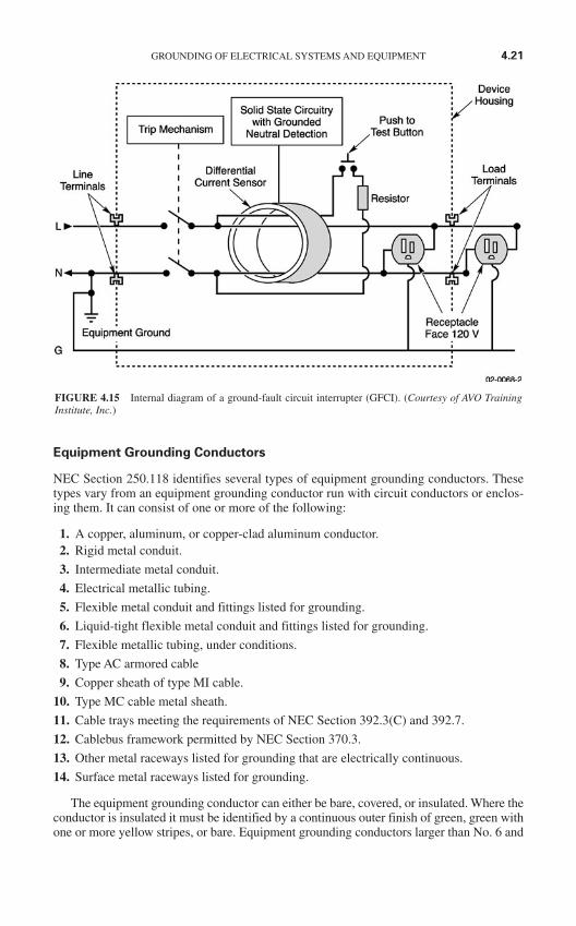
Equipment Grounding Conductors
NEC Section 250.118 identifies several types of equipment grounding conductors. Thesetypes vary from an equipment grounding conductor run with circuit conductors or enclos-ing them. It can consist of one or more of the following:
1. A copper, aluminum, or copper-clad aluminum conductor.2. Rigid metal conduit.
3. Intermediate metal conduit.
4. Electrical metallic tubing.
5. Flexible metal conduit and fittings listed for grounding.
6. Liquid-tight flexible metal conduit and fittings listed for grounding.
7. Flexible metallic tubing, under conditions.
8. Type AC armored cable
9. Copper sheath of type MI cable.
10. Type MC cable metal sheath.
11. Cable trays meeting the requirements of NEC Section 392.3(C) and 392.7.
12. Cablebus framework permitted by NEC Section 370.3.
13. Other metal raceways listed for grounding that are electrically continuous.
14. Surface metal raceways listed for grounding.
The equipment grounding conductor can either be bare, covered, or insulated. Where theconductor is insulated it must be identified by a continuous outer finish of green, green withone or more yellow stripes, or bare. Equipment grounding conductors larger than No. 6 and
GROUNDING OF ELECTRICAL SYSTEMS AND EQUIPMENT 4.21
FIGURE 4.15 Internal diagram of a ground-fault circuit interrupter (GFCI). (Courtesy of AVO TrainingInstitute, Inc.)
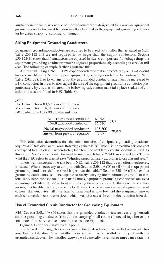
multiconductor cable, where one or more conductors are designated for use as an equipmentgrounding conductor, must be permanently identified as the equipment grounding conduc-tor by green stripping, coloring, or taping.
Sizing Equipment Grounding Conductors
Equipment grounding conductors are required to be sized not smaller than is stated in NECTable 250.122 and are not required to be larger than the supply conductors. Section250.122(B) states that if conductors are adjusted in size to compensate for voltage drop, theequipment grounding conductor must be adjusted proportionately according to circular milarea. The following example further illustrates this:
A circuit utilizing a No. 1 THW copper conductor that is protected by a 100-A circuitbreaker would use a No. 8 copper equipment grounding conductor (according to NECTable 250.122). Due to voltage drop, the ungrounded conductor size must be increased toa 1/0 conductor. In order to now adjust the size of the equipment grounding conductor pro-portionately by circular mil area, the following calculation must take place (values of cir-cular mil area are found in NEC Table 8):
givenNo. 1 conductor = 83,690 circular mil areaNo. 8 conductor = 16,510 circular mil area1/0 conductor = 105,600 circular mil area
This calculation determines that the minimum size of equipment grounding conductorrequires a 20,828 circular mil area. Referring again to NEC Table 8, it is noted that this does notcorrespond to a standard size conductor; therefore, the next larger conductor must be used. Inthis case, a No. 6 copper conductor must be used, which has a 26,240 circular mil area. This iswhat the NEC refers to when it says “adjusted proportionately according to circular mil area.”
There is an important note just below NEC Table 250.122 that is very often overlooked.It states, “Where necessary to comply with Section 250.4(A)(5) or (B)(4), the equipmentgrounding conductor shall be sized larger than this table.” Section 250.4(A)(5) states thatgrounding conductors “shall be capable of safely carrying the maximum ground-fault cur-rent likely to be imposed on it.” Too many times, equipment grounding conductors are sizedaccording to Table 250.122 without considering these other facts. In this case, the conduc-tor may not be able to safely carry the fault current. As was seen earlier, at a given value ofcurrent, the conductor will fuse (melt), the ground is now lost and the equipment case orenclosure would become energized, which would create a shock or electrocution hazard.
Use of Grounded Circuit Conductor for Grounding Equipment
NEC Section 250.24(A)(5) states that the grounded conductor (current-carrying neutral)and the grounding conductor (non-current-carrying) shall not be connected together on theload-side of the service disconnecting means (see Fig. 4.16).
Figure 4.17 further illustrates this point.The hazard of making this connection on the load-side is that a parallel return path has
now been established. The metallic raceway becomes a parallel return path with thegrounded conductor. The metallic raceway will generally have higher impedance than the
No.1 ungrounded conductor No.8 grounded conductor
No.1/0 ungrounded conductor answer from previous equation
= =
= =
83 69016 510
5 07
105 6005 07
20 828
,,
.
,.
,
4.22 CHAPTER FOUR
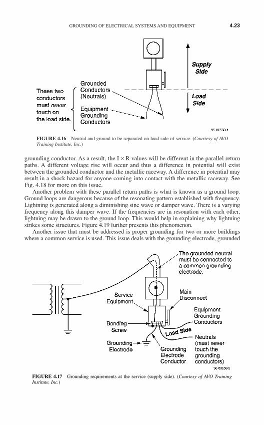
grounding conductor. As a result, the I × R values will be different in the parallel returnpaths. A different voltage rise will occur and thus a difference in potential will existbetween the grounded conductor and the metallic raceway. A difference in potential mayresult in a shock hazard for anyone coming into contact with the metallic raceway. SeeFig. 4.18 for more on this issue.
Another problem with these parallel return paths is what is known as a ground loop.Ground loops are dangerous because of the resonating pattern established with frequency.Lightning is generated along a diminishing sine wave or damper wave. There is a varyingfrequency along this damper wave. If the frequencies are in resonation with each other,lightning may be drawn to the ground loop. This would help in explaining why lightningstrikes some structures. Figure 4.19 further presents this phenomenon.
Another issue that must be addressed is proper grounding for two or more buildingswhere a common service is used. This issue deals with the grounding electrode, grounded
GROUNDING OF ELECTRICAL SYSTEMS AND EQUIPMENT 4.23
FIGURE 4.16 Neutral and ground to be separated on load side of service. (Courtesy of AVOTraining Institute, Inc.)
FIGURE 4.17 Grounding requirements at the service (supply side). (Courtesy of AVO TrainingInstitute, Inc.)
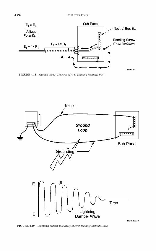
4.24 CHAPTER FOUR
FIGURE 4.18 Ground loop. (Courtesy of AVO Training Institute, Inc.)
FIGURE 4.19 Lightning hazard. (Courtesy of AVO Training Institute, Inc.)
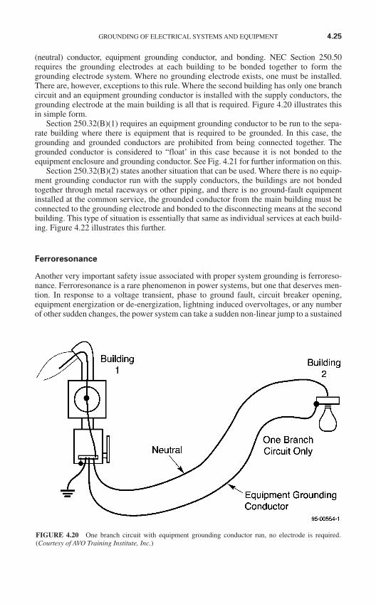
(neutral) conductor, equipment grounding conductor, and bonding. NEC Section 250.50requires the grounding electrodes at each building to be bonded together to form thegrounding electrode system. Where no grounding electrode exists, one must be installed.There are, however, exceptions to this rule. Where the second building has only one branchcircuit and an equipment grounding conductor is installed with the supply conductors, thegrounding electrode at the main building is all that is required. Figure 4.20 illustrates thisin simple form.
Section 250.32(B)(1) requires an equipment grounding conductor to be run to the sepa-rate building where there is equipment that is required to be grounded. In this case, thegrounding and grounded conductors are prohibited from being connected together. Thegrounded conductor is considered to “float’ in this case because it is not bonded to theequipment enclosure and grounding conductor. See Fig. 4.21 for further information on this.
Section 250.32(B)(2) states another situation that can be used. Where there is no equip-ment grounding conductor run with the supply conductors, the buildings are not bondedtogether through metal raceways or other piping, and there is no ground-fault equipmentinstalled at the common service, the grounded conductor from the main building must beconnected to the grounding electrode and bonded to the disconnecting means at the secondbuilding. This type of situation is essentially that same as individual services at each build-ing. Figure 4.22 illustrates this further.
Ferroresonance
Another very important safety issue associated with proper system grounding is ferroreso-nance. Ferroresonance is a rare phenomenon in power systems, but one that deserves men-tion. In response to a voltage transient, phase to ground fault, circuit breaker opening,equipment energization or de-energization, lightning induced overvoltages, or any numberof other sudden changes, the power system can take a sudden non-linear jump to a sustained
GROUNDING OF ELECTRICAL SYSTEMS AND EQUIPMENT 4.25
FIGURE 4.20 One branch circuit with equipment grounding conductor run, no electrode is required.(Courtesy of AVO Training Institute, Inc.)
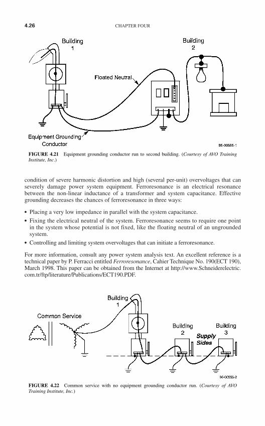
condition of severe harmonic distortion and high (several per-unit) overvoltages that canseverely damage power system equipment. Ferroresonance is an electrical resonancebetween the non-linear inductance of a transformer and system capacitance. Effectivegrounding decreases the chances of ferroresonance in three ways:
Placing a very low impedance in parallel with the system capacitance. Fixing the electrical neutral of the system. Ferroresonance seems to require one point
in the system whose potential is not fixed, like the floating neutral of an ungroundedsystem.
Controlling and limiting system overvoltages that can initiate a ferroresonance.
For more information, consult any power system analysis text. An excellent reference is atechnical paper by P. Ferracci entitled Ferroresonance, Cahier Technique No. 190(ECT 190),March 1998. This paper can be obtained from the Internet at http://www.Schneiderelectric.com.tr/ftp/literature/Publications/ECT190.PDF.
4.26 CHAPTER FOUR
FIGURE 4.21 Equipment grounding conductor run to second building. (Courtesy of AVO TrainingInstitute, Inc.)
FIGURE 4.22 Common service with no equipment grounding conductor run. (Courtesy of AVOTraining Institute, Inc.)
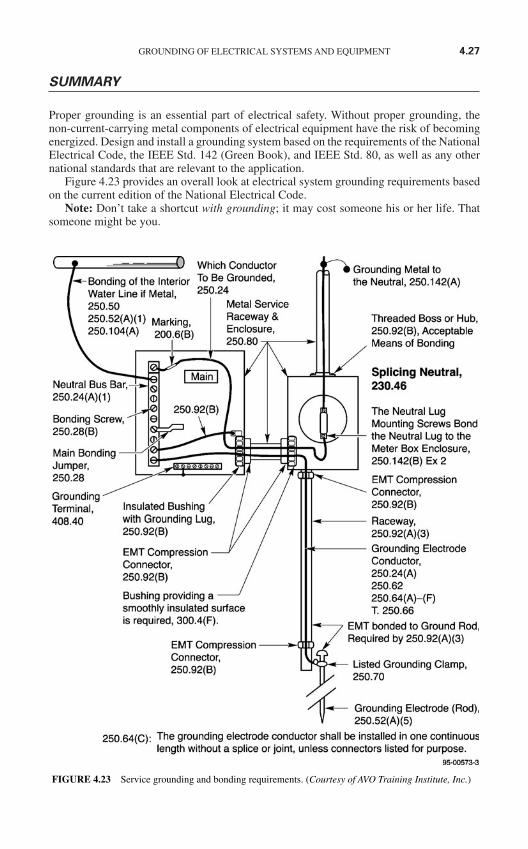
SUMMARY
Proper grounding is an essential part of electrical safety. Without proper grounding, thenon-current-carrying metal components of electrical equipment have the risk of becomingenergized. Design and install a grounding system based on the requirements of the NationalElectrical Code, the IEEE Std. 142 (Green Book), and IEEE Std. 80, as well as any othernational standards that are relevant to the application.
Figure 4.23 provides an overall look at electrical system grounding requirements basedon the current edition of the National Electrical Code.
Note: Don’t take a shortcut with grounding; it may cost someone his or her life. Thatsomeone might be you.
GROUNDING OF ELECTRICAL SYSTEMS AND EQUIPMENT 4.27
FIGURE 4.23 Service grounding and bonding requirements. (Courtesy of AVO Training Institute, Inc.)

This page intentionally left blank
ELECTRICAL MAINTENANCEAND ITS RELATIONSHIP
TO SAFETY
INTRODUCTION
All maintenance and testing of the electrical protective devices addressed in this chaptermust be accomplished in accordance with the manufacturer’s instructions. The NETA“Maintenance Testing Specifications for Electrical Power Distribution Equipment andSystems”1 2005 Edition is an excellent source of information for performing the requiredmaintenance and testing of these devices. Visit the NETA website (http://www.netaworld.org) for further information.
Because of the electrical hazards to which they may be exposed, all workers involved in elec-trical testing and maintenance must be qualified personnel as defined in the OSHA and NFPAstandards. NFPA 70B, Recommended Practice for Electrical Equipment Maintenance, statesthat equipment deterioration is normal, but equipment failure is not inevitable. Normal deterio-ration begins as soon as new equipment is installed and if unchecked can eventually cause equip-ment failure. Deterioration can be accelerated by factors such as environment, overload, orsevere duty cycles. A periodic maintenance program can identify these factors and provide mea-sures for coping with them. There are other potential causes of equipment failure that can alsobe detected and corrected. Among these are load changes or additions, circuit alterations,improperly set or improperly selected protective devices, and changing voltage conditions.2
Without an effective periodic maintenance and testing program, management assumesa greatly increased risk of a serious electrical failure and its consequences. An effectiveelectrical preventive maintenance program can reduce accidents, save lives, and minimizecostly breakdowns and unplanned shutdowns of production equipment. Failures can beaverted by identifying and correcting impending troubles before they become major prob-lems requiring more expensive, time consuming solutions.2
THE SAFETY-RELATED CASE FOR ELECTRICALMAINTENANCE
Overview
The relationship between safety and preventive maintenance is not a difficult one to estab-lish. Properly designed equipment that is properly installed is well capable of doing its job
5.1
CHAPTER 5
Copyright © 2006 by The McGraw-Hill Companies, Inc. Click here for terms of use.
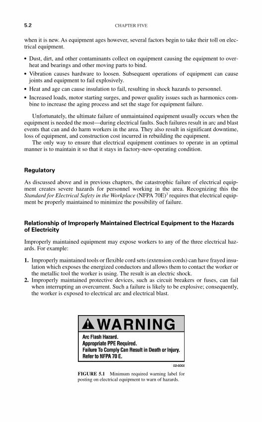
5.2 CHAPTER FIVE
when it is new. As equipment ages however, several factors begin to take their toll on elec-trical equipment.
Dust, dirt, and other contaminants collect on equipment causing the equipment to over-heat and bearings and other moving parts to bind.
Vibration causes hardware to loosen. Subsequent operations of equipment can causejoints and equipment to fail explosively.
Heat and age can cause insulation to fail, resulting in shock hazards to personnel. Increased loads, motor starting surges, and power quality issues such as harmonics com-
bine to increase the aging process and set the stage for equipment failure.
Unfortunately, the ultimate failure of unmaintained equipment usually occurs when theequipment is needed the most—during electrical faults. Such failures result in arc and blastevents that can and do harm workers in the area. They also result in significant downtime,loss of equipment, and construction cost incurred in rebuilding the equipment.
The only way to ensure that electrical equipment continues to operate in an optimalmanner is to maintain it so that it stays in factory-new-operating condition.
Regulatory
As discussed above and in previous chapters, the catastrophic failure of electrical equip-ment creates severe hazards for personnel working in the area. Recognizing this theStandard for Electrical Safety in the Workplace (NFPA 70E)3 requires that electrical equip-ment be properly maintained to minimize the possibility of failure.
Relationship of Improperly Maintained Electrical Equipment to the Hazardsof Electricity
Improperly maintained equipment may expose workers to any of the three electrical haz-ards. For example:
1. Improperly maintained tools or flexible cord sets (extension cords) can have frayed insu-lation which exposes the energized conductors and allows them to contact the worker orthe metallic tool the worker is using. The result is an electric shock.
2. Improperly maintained protective devices, such as circuit breakers or fuses, can failwhen interrupting an overcurrent. Such a failure is likely to be explosive; consequently,the worker is exposed to electrical arc and electrical blast.
FIGURE 5.1 Minimum required warning label forposting on electrical equipment to warn of hazards.
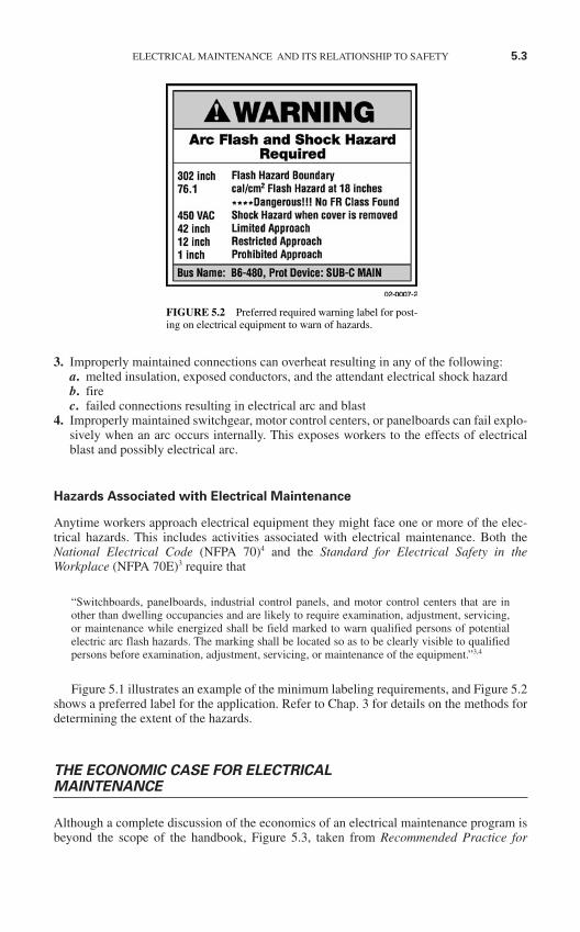
3. Improperly maintained connections can overheat resulting in any of the following:a. melted insulation, exposed conductors, and the attendant electrical shock hazardb. firec. failed connections resulting in electrical arc and blast
4. Improperly maintained switchgear, motor control centers, or panelboards can fail explo-sively when an arc occurs internally. This exposes workers to the effects of electricalblast and possibly electrical arc.
Hazards Associated with Electrical Maintenance
Anytime workers approach electrical equipment they might face one or more of the elec-trical hazards. This includes activities associated with electrical maintenance. Both theNational Electrical Code (NFPA 70)4 and the Standard for Electrical Safety in theWorkplace (NFPA 70E)3 require that
“Switchboards, panelboards, industrial control panels, and motor control centers that are inother than dwelling occupancies and are likely to require examination, adjustment, servicing,or maintenance while energized shall be field marked to warn qualified persons of potentialelectric arc flash hazards. The marking shall be located so as to be clearly visible to qualifiedpersons before examination, adjustment, servicing, or maintenance of the equipment.”3,4
Figure 5.1 illustrates an example of the minimum labeling requirements, and Figure 5.2shows a preferred label for the application. Refer to Chap. 3 for details on the methods fordetermining the extent of the hazards.
THE ECONOMIC CASE FOR ELECTRICALMAINTENANCE
Although a complete discussion of the economics of an electrical maintenance program isbeyond the scope of the handbook, Figure 5.3, taken from Recommended Practice for
ELECTRICAL MAINTENANCE AND ITS RELATIONSHIP TO SAFETY 5.3
FIGURE 5.2 Preferred required warning label for post-ing on electrical equipment to warn of hazards.
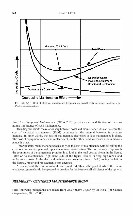
Electrical Equipment Maintenance (NFPA 70B)2 provides a clear definition of the eco-nomic importance of such maintenance.
This diagram charts the relationship between costs and maintenance. As can be seen, thecost of electrical maintenance (EPM) decreases as the interval between inspectionsincrease. In other words, the cost of maintenance decreases as less maintenance is done.The cost of equipment repair and replacement, on the other hand, increases as less mainte-nance is done.
Unfortunately, many managers focus only on the cost of maintenance without taking thecosts of equipment repair and replacement into consideration. The correct way to approachthe economics of a maintenance program is to look at the total cost as shown in the figure.Little or no maintenance (right-hand side of the figure) results in very high repair andreplacement costs. As the electrical maintenance program is intensified (moving the left onthe figure), repair and replacement costs decrease.
At some point, the minimum total cost is realized. This is the point at which the main-tenance program should be operated to provide for the best overall efficiency of the system.
RELIABILITY CENTERED MAINTENANCE (RCM)
(The following paragraphs are taken from RCM White Paper by Al Rose, (c) CadickCorporation, 2001–2005)
5.4 CHAPTER FIVE
FIGURE 5.3 Effect of electrical maintenance frequency on overall costs. (Courtesy National FireProtection Association.)
What is Reliability Centered Maintenance?
Reliability-Centered Maintenance (RCM) is the process of determining the most effectivemaintenance approach. The RCM philosophy employs Preventive Maintenance (PM),Predictive Maintenance (PdM), Real-time Monitoring (RTM), Run-to-Failure (RTF- alsocalled reactive maintenance) and Proactive Maintenance techniques in an integrated man-ner to increase the probability that a machine or component will function in the requiredmanner over its design life cycle with a minimum of maintenance. The goal of the philoso-phy is to provide the stated function of the facility, with the required reliability and avail-ability at the lowest cost. RCM requires that maintenance decisions be based on maintenancerequirements supported by sound, technical, and economic justification.
A Brief History of RCM
RCM originated in the Airline industry in the 1960s. By the late 1950s, the cost of mainte-nance activities in this industry had become high enough to warrant a special investigationinto the effectiveness of those activities. Accordingly, in 1960, a task force was formed con-sisting of representatives of both the airlines and the Federal Aviation Administration (FAA)to investigate the capabilities of preventive maintenance. The establishment of this task forcesubsequently led to the development of a series of guidelines for airlines and aircraft manu-facturers to use, when establishing maintenance schedules for their aircraft.
This led to the 747 Maintenance Steering Group (MSG) document MSG-1; Handbook:Maintenance Evaluation and Program Development from the Air Transport Association in1968. MSG-1 was used to develop the maintenance program for the Boeing 747 aircraft, thefirst maintenance program to apply RCM concepts. MSG-2, the next revision, was used todevelop the maintenance programs for the Lockheed L-1011 and the Douglas DC-10. The suc-cess of this program is demonstrated by comparing maintenance requirements of a DC-8 air-craft, maintained using standard maintenance techniques, and the DC-10 aircraft, maintainedusing MSG-2 guidelines. The DC-8 aircraft has 339 items that require an overhaul, verses onlyseven items on a DC-10. Using another example, the original Boeing 747 required 66,000 laborhours on major structural inspections before a major heavy inspection at 20,000 operatinghours. In comparison, the DC-8 - a smaller and less sophisticated aircraft using standard main-tenance programs of the day required more than 4 million labor hours before reaching 20,000operating hours.
In 1974 the U.S. Department of Defense commissioned United Airlines to write a reporton the processes used in the civil aviation industry for the development of maintenance pro-grams for aircraft. This report, written by Stan Nowlan and Howard Heap and published in1978, was entitled Reliability Centered Maintenance,5 and has become the report uponwhich all subsequent Reliability Centered Maintenance approaches have been based. WhatNowlan and Heap found was that many types of failures could not be prevented no matterhow intensive the maintenance activities were. Additionally it was discovered that for manyitems the probability of failure did not increase with age. Consequently, a maintenance pro-gram based on age will have little, if any effect on the failure rate.
RCM in the Industrial and Utility Arena
As with any philosophy, there are many paths, or processes that lead to a final goal. This isespecially true for RCM where the consequences of failure can vary dramatically.
Rigorous RCM analysis has been used extensively by the aircraft, space, defense, andnuclear industries where functional failures have the potential to result in large losses oflife, national security implications, and/or extreme environmental impact. A rigorous RCM
ELECTRICAL MAINTENANCE AND ITS RELATIONSHIP TO SAFETY 5.5
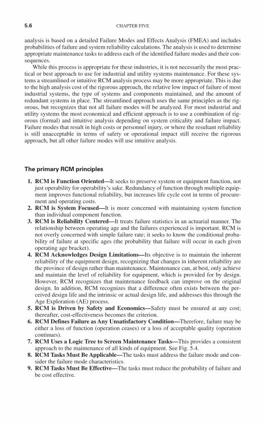
analysis is based on a detailed Failure Modes and Effects Analysis (FMEA) and includesprobabilities of failure and system reliability calculations. The analysis is used to determineappropriate maintenance tasks to address each of the identified failure modes and their con-sequences.
While this process is appropriate for these industries, it is not necessarily the most prac-tical or best approach to use for industrial and utility systems maintenance. For these sys-tems a streamlined or intuitive RCM analysis process may be more appropriate. This is dueto the high analysis cost of the rigorous approach, the relative low impact of failure of mostindustrial systems, the type of systems and components maintained, and the amount ofredundant systems in place. The streamlined approach uses the same principles as the rig-orous, but recognizes that not all failure modes will be analyzed. For most industrial andutility systems the most economical and efficient approach is to use a combination of rig-orous (formal) and intuitive analysis depending on system criticality and failure impact.Failure modes that result in high costs or personnel injury, or where the resultant reliabilityis still unacceptable in terms of safety or operational impact still receive the rigorousapproach, but all other failure modes will use intuitive analysis.
The primary RCM principles
1. RCM is Function Oriented—It seeks to preserve system or equipment function, notjust operability for operability’s sake. Redundancy of function through multiple equip-ment improves functional reliability, but increases life cycle cost in terms of procure-ment and operating costs.
2. RCM is System Focused—It is more concerned with maintaining system functionthan individual component function.
3. RCM is Reliability Centered—It treats failure statistics in an actuarial manner. Therelationship between operating age and the failures experienced is important. RCM isnot overly concerned with simple failure rate; it seeks to know the conditional proba-bility of failure at specific ages (the probability that failure will occur in each givenoperating age bracket).
4. RCM Acknowledges Design Limitations—Its objective is to maintain the inherentreliability of the equipment design, recognizing that changes in inherent reliability arethe province of design rather than maintenance. Maintenance can, at best, only achieveand maintain the level of reliability for equipment, which is provided for by design.However, RCM recognizes that maintenance feedback can improve on the originaldesign. In addition, RCM recognizes that a difference often exists between the per-ceived design life and the intrinsic or actual design life, and addresses this through theAge Exploration (AE) process.
5. RCM is Driven by Safety and Economics—Safety must be ensured at any cost;thereafter, cost-effectiveness becomes the criterion.
6. RCM Defines Failure as Any Unsatisfactory Condition—Therefore, failure may beeither a loss of function (operation ceases) or a loss of acceptable quality (operationcontinues).
7. RCM Uses a Logic Tree to Screen Maintenance Tasks—This provides a consistentapproach to the maintenance of all kinds of equipment. See Fig. 5.4.
8. RCM Tasks Must Be Applicable—The tasks must address the failure mode and con-sider the failure mode characteristics.
9. RCM Tasks Must Be Effective—The tasks must reduce the probability of failure andbe cost effective.
5.6 CHAPTER FIVE
10. RCM Acknowledges Three Types of Maintenance Tasksa. Time-directed (PM)—Scheduled when appropriateb. Condition-directed (PdM and real-time monitoring)—Performed when conditions
indicate they are neededc. Failure finding (one of several aspects of Proactive Maintenance)—Equipment is
run-to-failure. This is acceptable for some situations and some types of equipment. 11. RCM is a Living System—It gathers data from the results achieved and feeds this data
back to improve design and future maintenance. This feedback is an important part ofthe Proactive Maintenance element of the RCM program.
The RCM analysis carefully considers the following questions:
1. What does the system or equipment do; what is its function?
2. What functional failures are likely to occur?
ELECTRICAL MAINTENANCE AND ITS RELATIONSHIP TO SAFETY 5.7
FIGURE 5.4 RCM Logic Tree.
3. What are the likely consequences of these functional failures?
4. What can be done to reduce the probability of the failure, identify the onset of failure,or reduce the consequences of the failure?
Answers to these four questions determine the necessary actions required to maintain thesystems or equipment. Figure 1 shows the RCM logic tree used to answer these questions.
Failure
Failure can be defined in many ways. In a broad sense failure is simply an unsatisfactorycondition. RCM, however, requires us to look at failure from not just an equipment stand-point, but from a system standpoint as well. A piece of equipment can be operating (anHVAC unit in a clean room, for example), but if its output is less than required it would beconsidered failed. On the other hand, a protective relay in a power system can have failed,but if it has not taken the circuit off-line (the circuit is still energized) the function of thesystem is unchanged. Essentially, defining failure depends on the function of an item or sys-tem and the operating context in which the item or system is used.
Functional Failure. A functional failure is essentially the inability of an item or systemto meet its specified performance standard. A complete loss of function is a functional fail-ure; however, in the HVAC example above if the system’s output is less than specified, afunctional failure has occurred even if the system is still operating.
Consequences of Failure. The consequences of failure determine the priority of mainte-nance activities or design improvement required to prevent occurrence. If failure of an itemresults in little or no consequence, mimimal maintenance activities are generally required.If, however, failure of an item results in a large economic hardship, personnel injury, orenvironmental damage maximum maintenance activities or a redesign may be called for.
Maintenance Actions in an RCM Program
RCM goals are to identify the most cost-effective and applicable maintenance techniquesto minimize the risk and impact of failure in facility and utility equipment and systems. Thisallows systems and equipment functionality to be maintained in the most economical man-ner. Specific RCM objectives as stated by Nowlan and Heap5 are:
To ensure realization of the inherent safety and reliability levels of the equipment. To restore the equipment to these inherent levels when deterioration occurs. To obtain the information necessary for design improvement of those items whose inher-
ent reliability proves to be inadequate. To accomplish these goals at a minimum total cost, including maintenance costs, support
costs, and economic consequences of operational failures.
To this end there are four outcomes from an RCM analysis:
1. Perform no Maintenance—This is referred to as reactive maintenance, repair, fix-on-fail, or Run-To-Fail (RTF). This type of maintenance assumes that failure is equallylikely to occur in any part, and that a failure is not detrimental to the operation. Whenthis is the sole type of maintenance practiced high failure rates, large parts inventories,and excessive amounts of overtime become common. A purely RTF maintenance pro-gram ignores many of the opportunities to influence equipment survivability.
5.8 CHAPTER FIVE
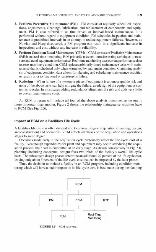
2. Perform Preventive Maintenance (PM)—PM consists of regularly scheduled inspec-tions, adjustments, cleanings, lubrication, and replacement of components and equip-ment. PM is also referred to as time-driven or interval-based maintenance. It isperformed without regard to equipment condition. PM schedules inspection and main-tenance at predefined intervals in an attempt to reduce equipment failures. However, asNowlan and Heap discovered, a PM program can result in a significant increase ininspections and cost without any increase in reliability.
3. Perform Condition Based Maintenance (CBM)—CBM consists of Predictive Maintenance(PdM) and real-time monitoring. PdM primarily uses non-intrusive testing techniques to mea-sure and trend equipment performance. Real-time monitoring uses current performance datato asses machinery condition. CBM replaces arbitrarily timed maintenance tasks with main-tenance that is scheduled only when warranted by equipment condition. Continuing analy-sis of equipment condition data allows for planning and scheduling maintenance activitiesor repairs prior to functional or catastrophic failure.
4. Redesign—When failure of a system or piece of equipment is an unacceptable risk andnone of the above tasks can help mitigate the failure, a redesign of the equipment or sys-tem is in order. In most cases adding redundancy eliminates the risk and adds very littleto overall maintenance costs.
An RCM program will include all four of the above analysis outcomes, as no one ismore important than another. Figure 2 shows the relationship maintenance activities haveto RCM (See Fig. 5.5).
Impact of RCM on a Facilities Life Cycle
A facilities life cycle is often divided into two broad stages: acquisition (planning, design,and construction) and operations. RCM affects all phases of the acquisition and operationsstages to some degree.
Decisions made early in the acquisition cycle profoundly affect the life-cycle cost of afacility. Even though expenditures for plant and equipment may occur later during the acqui-sition process, their cost is committed at an early stage. As shown conceptually in Fig. 5.6,planning (including conceptual design) fixes two-thirds of the facility’s overall life-cyclecosts. The subsequent design phases determine an additional 29 percent of the life-cycle cost,leaving only about 5 percent of the life-cycle cost that can be impacted by the later phases.
Thus, the decision to include a facility in an RCM program, including condition moni-toring which will have a major impact on its life-cycle cost, is best made during the planning
ELECTRICAL MAINTENANCE AND ITS RELATIONSHIP TO SAFETY 5.9
FIGURE 5.5 RCM structure.
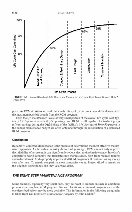
phase. As RCM decisions are made later in the life cycle, it becomes more difficult to achievethe maximum possible benefit from the RCM program.
Even though maintenance is a relatively small portion of the overall life-cycle cost, typ-ically 3 to 5 percent of a facility’s operating cost, RCM is still capable of introducing sig-nificant savings during the O&M phase of the facility’s life. Savings of 30 to 50 percent inthe annual maintenance budget are often obtained through the introduction of a balancedRCM program.
Conclusion
Reliability-Centered Maintenance is the process of determining the most effective mainte-nance approach. As the airline industry showed 40 years ago, RCM can not only improvethe reliability of a system, it can significantly reduce the required maintenance. In today’scompetitive world economy that translates into monies saved, both from reduced failuresand reduced work. And a properly implemented RCM program will continue saving moneyyear after year. To remain competitive most companies can no longer afford to remain onthe sidelines doing things like they’ve always done.
THE EIGHT STEP MAINTENANCE PROGRAM
Some facilities, especially very small ones, may not want to embark on such an ambitiousprocess as a complete RCM program. For such locations, a minimal program such as theone described below may be more desirable. This information in the following paragraphsis taken from The Eight Step Maintenance Program by John Cadick.6
5.10 CHAPTER FIVE
FIGURE 5.6 Source Blanchard, B.S, Design and Manage to Life Cycle Cost, Forest Grove, OR, MAPress, 1978
Introduction
There are eight simple steps that should be at the heart of an electrical preventive mainte-nance program. These key steps are plan, inspect, clean, tighten, lubricate, test, record, andevaluate. The following paragraphs briefly describe each step and illustrate the part thatthey play in a good preventive maintenance program.
Step 1—Plan
Before working on anything, take time to think about what you are going to do and how youare going to do it. A few minutes of thought before the job is started results in a safer andmore efficient job. This step is especially important when you are performing emergencyrepair work.
Start by identifying the specific task or tasks that you intend to perform. In this initialstage you do not need to go into too much detail, rather, concentrate on the broad goals thatyou need to accomplish. List each goal, the personnel that you will use, the equipment thatyou will need, and the amount of time that will be required.
Be certain that you obtain and use the proper instruction manuals and design drawingsbefore you start. The joke of “getting the manual after smoke is present” has too much basisin fact to be very funny for experienced electricians. Trouble shooting without accurate andcorrect schematics and wiring diagrams is close to impossible in all but the simplest circuits.
Develop detailed plans and procedures from the preliminary plans discussed above.Steps should be detailed as much as required by the complexity of the job and the experi-ence of your personnel.
Always start any procedure with a job briefing as described in Chap. 3.
Step 2—Inspect
Periodic inspections should be set up on a routine basis. Inspection can be done with thesenses that nature gave us, called unaided inspection, or with instruments such as infraredviewers, ultra sound transducers, and so on.
Unaided Inspection. Your eyes are your most important inspection tools. They can detectdirt, note current readings, determine levels, discover discolored, overheated insulation,determine the presence of insects and rodents, and find a whole host of other problems. Themore experienced you become, the more information your eyes can provide; however, eventhe most inexperienced electrician can detect spider webs in a circuit breaker operatingmechanism. Always observe what you are working on and look for any abnormalities thatcan give you an idea of any thing that can cause these problems.
Your ears can also be useful inspection tools. Overloaded transformers are normallynoisier than lightly loaded ones, corona has a distinctive hissing sound, and motors withunbalanced voltages or bad bearings vibrate. Any change in sound should be investigated.
Nothing in electrical systems is more distinctive than the odor of overheated or burninginsulation. Your nose can detect such problems long before your other senses. Again, themost useful indicator of problems is a change in odor.
Touch may also be employed to inspect electrical equipment. Feeling for excessivevibration or heating is a time-tested technique. Of course, you should be extremely cautiousbefore touching any piece of equipment. If the equipment is not de-energized, contactshould be made only when wearing appropriate insulating PPE, such as rubber gloves.
Inspection with Tools or Instruments. Except for your own senses, infrared viewers arethe most cost-effective maintenance tool in existence. Annual infrared scans of your power
ELECTRICAL MAINTENANCE AND ITS RELATIONSHIP TO SAFETY 5.11
system invariably discover problems which, if allowed to continue, could result in severeproblems. Whether this service is done “in house” or contracted to an outside service, youshould perform an annual (minimum) infrared scan of your system.
Ultrasound transducers are normally used on major overhauls to evaluate the conditionof metals which are subjected to constant vibration.
Many other such tools and instruments are available to help in the performance of main-tenance tasks. Such tools should be used as required by qualified personnel trained in theirproper and safe use.
Step 3—Clean
Dirt and electricity don’t mix. After you have completed the inspection of your electricalequipment, the next step is to clean all components.
The first step is general cleanliness. Dust, dirt, and foreign material must be cleanedfrom motors, switchgear, transformers, and other such electrical equipment. For such clean-ing we recommend the use of high suction, insulated hose shop vacuum, clean, lint freewiping cloth, and general purpose solvents. A citrus-based general purpose solvent is effec-tive and biodegradable.
Each insulator or conductor has its own way to be cleaned. Porcelain, for example, canbe cleaned with soap, water, and appropriate cleaning brushes or pads. Plastic insulation,on the other hand, cannot take any abrasion. Always refer to the manufacturer’s recom-mendations for specific techniques. Also, always avoid using steel wool or other conduc-tive abrasives in any area where contact with energized conductors is possible.
Conductor connecting surfaces need special attention. Contact surfaces of copperconductors should be cleaned to a bright finish where they are connected together.Aluminium must be cleaned and a protective lubricant must be applied immediately afterthe cleaning. The lubricant cuts through any aluminum oxide (a good insulator) that maybe present, and prevents the formation of additional aluminium oxide. (See the section onlubrication.)
Refer to the manufacturer’s instruction books, which sometimes specify the cleaningmaterial to be used for their equipment. Be sure to consult this literature before attemptingto clean electrical components.
Step 4—Tighten
Tightening fasteners on electrical equipment takes special care and should be done to thetorque recommended by the equipment manufacturer. Electrical connections are especiallycritical. Recommendations for recommended torque values can be found in the mainte-nance and acceptance testing specifications published by the InterNational ElectricalTesting Association.1 Be certain to torque connections per this table and/or manufacturer’srecommendations.
Step 5—Lubricate
Lubrication of electrical system components is an often overlooked or improperly per-formed procedure. Too much lubricant can be worse than no lubricant at all. This is espe-cially true of devices such as protective relays and circuit breakers which may go foryears without operating. Be especially careful of conductive lubricants to make sure theydo not cause a short circuit. Always use the lubricants recommended by the equipment
5.12 CHAPTER FIVE
manufacturer or one that has the same characteristics. Lubrication falls into two impor-tant areas:
1. Non-conductors
Non-conductive joints or moving members should be lubricated using an appropriatematerial. In some cases grease, oil, or some synthetic lubricant may be recommended.Motor bearings, mechanism pivots, and other such equipment fall into this category.Remember that some pieces of equipment, such as protective relays, do not require anylubricant at all.
2. Conductors
Most manufacturers make and/or recommend a lubricant to be used on conductors, stabs,and other such equipment. The ubiquitous “black grease” has been and continues to be agood lubricant when used properly. The correct approach to lubrication of electrical con-ductors is to apply a small amount and then wipe the contact surface clean with a clean,lint free cloth. Do not scrub the surface however. You wish to leave a fine film of lubricantin place.
Remember: Use the proper lubricants in the proper amounts.
Step 6—Test
Electrical equipment should be tested periodically. Insulation resistance should be mea-sured, breaker trip times should be checked, relays should be calibrated, and a variety ofother procedures should be performed. The only exercise that many protective devices getis during the test interval.
A detailed review of all procedures is beyond the scope of this course; however, the rec-ommendations made by the InterNational Electrical Testing Association (NETA) in theirpublication entitled Maintenance Testing Specifications1 should be reviewed and applied asappropriate.
Step 7—Record
Doing work without keeping records is almost useless. Recording test and other data can helpset maintenance intervals, isolate troublesome equipment (or manufacturers), and provide abaseline that helps to know when insulation or other components are starting to fail. Besidestest results records should always include the date, equipment identification, and all pertinentdata on any problems discovered. System conditions like load current, voltage, temperature,and other such information can help determine how close components are to being overloaded.
Test and record forms should be developed and tailored to your company’s specificneeds. Examples of such forms may be found at the back of the NFPA 70B ElectricalEquipment Maintenance. Review that document for ideas and examples.
Step 8—Evaluate
Evaluation of the test results is, possibly, the single most important step in the entire pro-cess. Since 1990, significant progress has been made in the statistical analysis of smallpopulation data such as that gathered during maintenance intervals. Whether the analysisis done using sophisticated mathematical techniques or simple field rules of thumb, noprogram is complete without it. Analysis of records will allow the company to determine
ELECTRICAL MAINTENANCE AND ITS RELATIONSHIP TO SAFETY 5.13
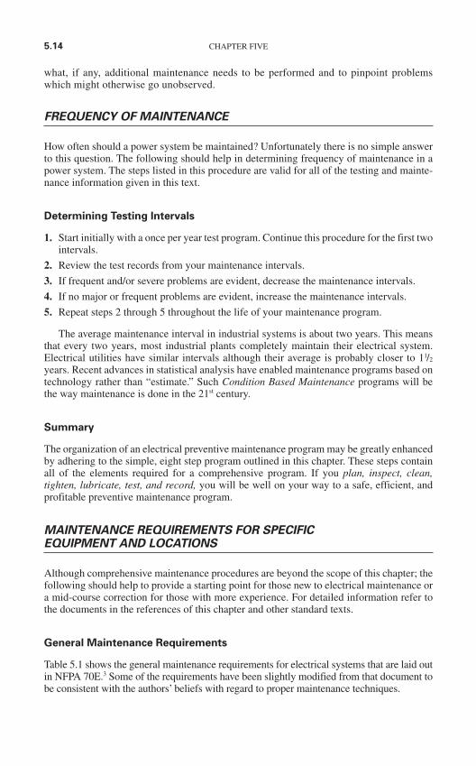
what, if any, additional maintenance needs to be performed and to pinpoint problemswhich might otherwise go unobserved.
FREQUENCY OF MAINTENANCE
How often should a power system be maintained? Unfortunately there is no simple answerto this question. The following should help in determining frequency of maintenance in apower system. The steps listed in this procedure are valid for all of the testing and mainte-nance information given in this text.
Determining Testing Intervals
1. Start initially with a once per year test program. Continue this procedure for the first twointervals.
2. Review the test records from your maintenance intervals.
3. If frequent and/or severe problems are evident, decrease the maintenance intervals.
4. If no major or frequent problems are evident, increase the maintenance intervals.
5. Repeat steps 2 through 5 throughout the life of your maintenance program.
The average maintenance interval in industrial systems is about two years. This meansthat every two years, most industrial plants completely maintain their electrical system.Electrical utilities have similar intervals although their average is probably closer to 11/2
years. Recent advances in statistical analysis have enabled maintenance programs based ontechnology rather than “estimate.” Such Condition Based Maintenance programs will bethe way maintenance is done in the 21st century.
Summary
The organization of an electrical preventive maintenance program may be greatly enhancedby adhering to the simple, eight step program outlined in this chapter. These steps containall of the elements required for a comprehensive program. If you plan, inspect, clean,tighten, lubricate, test, and record, you will be well on your way to a safe, efficient, andprofitable preventive maintenance program.
MAINTENANCE REQUIREMENTS FOR SPECIFICEQUIPMENT AND LOCATIONS
Although comprehensive maintenance procedures are beyond the scope of this chapter; thefollowing should help to provide a starting point for those new to electrical maintenance ora mid-course correction for those with more experience. For detailed information refer tothe documents in the references of this chapter and other standard texts.
General Maintenance Requirements
Table 5.1 shows the general maintenance requirements for electrical systems that are laid outin NFPA 70E.3 Some of the requirements have been slightly modified from that document tobe consistent with the authors’ beliefs with regard to proper maintenance techniques.
5.14 CHAPTER FIVE
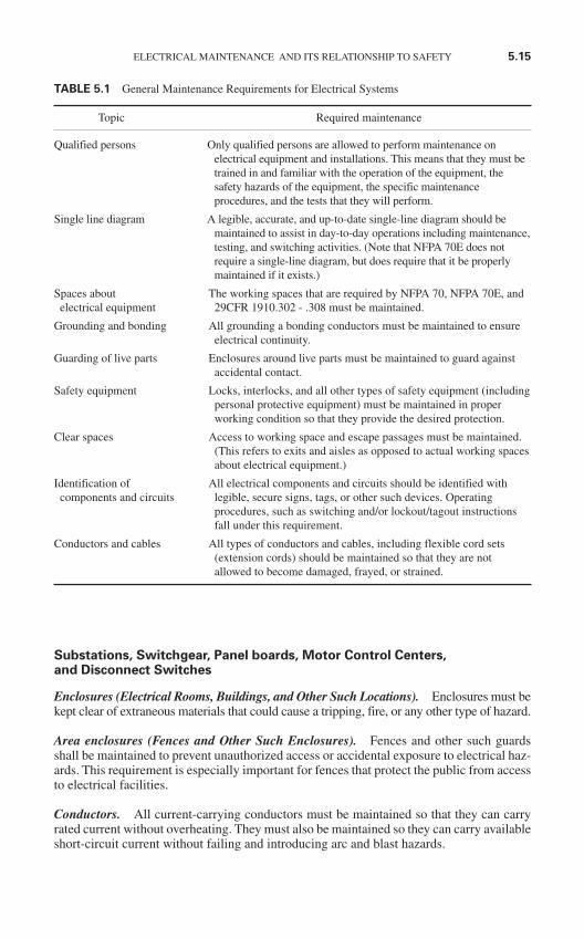
Substations, Switchgear, Panel boards, Motor Control Centers, and Disconnect Switches
Enclosures (Electrical Rooms, Buildings, and Other Such Locations). Enclosures must bekept clear of extraneous materials that could cause a tripping, fire, or any other type of hazard.
Area enclosures (Fences and Other Such Enclosures). Fences and other such guardsshall be maintained to prevent unauthorized access or accidental exposure to electrical haz-ards. This requirement is especially important for fences that protect the public from accessto electrical facilities.
Conductors. All current-carrying conductors must be maintained so that they can carryrated current without overheating. They must also be maintained so they can carry availableshort-circuit current without failing and introducing arc and blast hazards.
ELECTRICAL MAINTENANCE AND ITS RELATIONSHIP TO SAFETY 5.15
TABLE 5.1 General Maintenance Requirements for Electrical Systems
Topic Required maintenance
Qualified persons Only qualified persons are allowed to perform maintenance on electrical equipment and installations. This means that they must betrained in and familiar with the operation of the equipment, thesafety hazards of the equipment, the specific maintenanceprocedures, and the tests that they will perform.
Single line diagram A legible, accurate, and up-to-date single-line diagram should be maintained to assist in day-to-day operations including maintenance,testing, and switching activities. (Note that NFPA 70E does notrequire a single-line diagram, but does require that it be properlymaintained if it exists.)
Spaces about The working spaces that are required by NFPA 70, NFPA 70E, andelectrical equipment 29CFR 1910.302 - .308 must be maintained.
Grounding and bonding All grounding a bonding conductors must be maintained to ensure electrical continuity.
Guarding of live parts Enclosures around live parts must be maintained to guard against accidental contact.
Safety equipment Locks, interlocks, and all other types of safety equipment (includingpersonal protective equipment) must be maintained in properworking condition so that they provide the desired protection.
Clear spaces Access to working space and escape passages must be maintained. (This refers to exits and aisles as opposed to actual working spacesabout electrical equipment.)
Identification of All electrical components and circuits should be identified with components and circuits legible, secure signs, tags, or other such devices. Operating
procedures, such as switching and/or lockout/tagout instructionsfall under this requirement.
Conductors and cables All types of conductors and cables, including flexible cord sets (extension cords) should be maintained so that they are notallowed to become damaged, frayed, or strained.
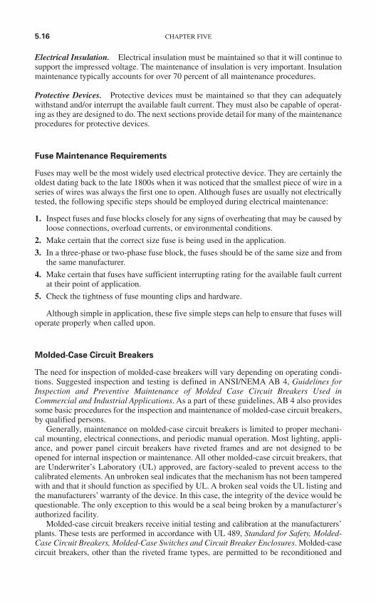
Electrical Insulation. Electrical insulation must be maintained so that it will continue tosupport the impressed voltage. The maintenance of insulation is very important. Insulationmaintenance typically accounts for over 70 percent of all maintenance procedures.
Protective Devices. Protective devices must be maintained so that they can adequatelywithstand and/or interrupt the available fault current. They must also be capable of operat-ing as they are designed to do. The next sections provide detail for many of the maintenanceprocedures for protective devices.
Fuse Maintenance Requirements
Fuses may well be the most widely used electrical protective device. They are certainly theoldest dating back to the late 1800s when it was noticed that the smallest piece of wire in aseries of wires was always the first one to open. Although fuses are usually not electricallytested, the following specific steps should be employed during electrical maintenance:
1. Inspect fuses and fuse blocks closely for any signs of overheating that may be caused byloose connections, overload currents, or environmental conditions.
2. Make certain that the correct size fuse is being used in the application.
3. In a three-phase or two-phase fuse block, the fuses should be of the same size and fromthe same manufacturer.
4. Make certain that fuses have sufficient interrupting rating for the available fault currentat their point of application.
5. Check the tightness of fuse mounting clips and hardware.
Although simple in application, these five simple steps can help to ensure that fuses willoperate properly when called upon.
Molded-Case Circuit Breakers
The need for inspection of molded-case breakers will vary depending on operating condi-tions. Suggested inspection and testing is defined in ANSI/NEMA AB 4, Guidelines forInspection and Preventive Maintenance of Molded Case Circuit Breakers Used inCommercial and Industrial Applications. As a part of these guidelines, AB 4 also providessome basic procedures for the inspection and maintenance of molded-case circuit breakers,by qualified persons.
Generally, maintenance on molded-case circuit breakers is limited to proper mechani-cal mounting, electrical connections, and periodic manual operation. Most lighting, appli-ance, and power panel circuit breakers have riveted frames and are not designed to beopened for internal inspection or maintenance. All other molded-case circuit breakers, thatare Underwriter’s Laboratory (UL) approved, are factory-sealed to prevent access to thecalibrated elements. An unbroken seal indicates that the mechanism has not been tamperedwith and that it should function as specified by UL. A broken seal voids the UL listing andthe manufacturers’ warranty of the device. In this case, the integrity of the device would bequestionable. The only exception to this would be a seal being broken by a manufacturer’sauthorized facility.
Molded-case circuit breakers receive initial testing and calibration at the manufacturers’plants. These tests are performed in accordance with UL 489, Standard for Safety, Molded-Case Circuit Breakers, Molded-Case Switches and Circuit Breaker Enclosures. Molded-casecircuit breakers, other than the riveted frame types, are permitted to be reconditioned and
5.16 CHAPTER FIVE
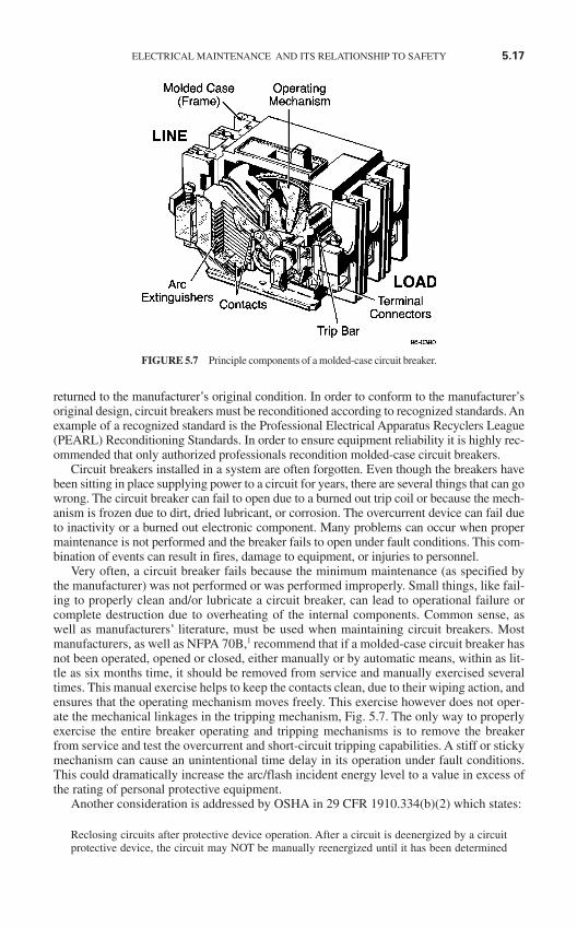
returned to the manufacturer’s original condition. In order to conform to the manufacturer’soriginal design, circuit breakers must be reconditioned according to recognized standards. Anexample of a recognized standard is the Professional Electrical Apparatus Recyclers League(PEARL) Reconditioning Standards. In order to ensure equipment reliability it is highly rec-ommended that only authorized professionals recondition molded-case circuit breakers.
Circuit breakers installed in a system are often forgotten. Even though the breakers havebeen sitting in place supplying power to a circuit for years, there are several things that can gowrong. The circuit breaker can fail to open due to a burned out trip coil or because the mech-anism is frozen due to dirt, dried lubricant, or corrosion. The overcurrent device can fail dueto inactivity or a burned out electronic component. Many problems can occur when propermaintenance is not performed and the breaker fails to open under fault conditions. This com-bination of events can result in fires, damage to equipment, or injuries to personnel.
Very often, a circuit breaker fails because the minimum maintenance (as specified bythe manufacturer) was not performed or was performed improperly. Small things, like fail-ing to properly clean and/or lubricate a circuit breaker, can lead to operational failure orcomplete destruction due to overheating of the internal components. Common sense, aswell as manufacturers’ literature, must be used when maintaining circuit breakers. Mostmanufacturers, as well as NFPA 70B,1 recommend that if a molded-case circuit breaker hasnot been operated, opened or closed, either manually or by automatic means, within as lit-tle as six months time, it should be removed from service and manually exercised severaltimes. This manual exercise helps to keep the contacts clean, due to their wiping action, andensures that the operating mechanism moves freely. This exercise however does not oper-ate the mechanical linkages in the tripping mechanism, Fig. 5.7. The only way to properlyexercise the entire breaker operating and tripping mechanisms is to remove the breakerfrom service and test the overcurrent and short-circuit tripping capabilities. A stiff or stickymechanism can cause an unintentional time delay in its operation under fault conditions.This could dramatically increase the arc/flash incident energy level to a value in excess ofthe rating of personal protective equipment.
Another consideration is addressed by OSHA in 29 CFR 1910.334(b)(2) which states:
Reclosing circuits after protective device operation. After a circuit is deenergized by a circuitprotective device, the circuit may NOT be manually reenergized until it has been determined
ELECTRICAL MAINTENANCE AND ITS RELATIONSHIP TO SAFETY 5.17
FIGURE 5.7 Principle components of a molded-case circuit breaker.
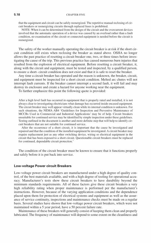
that the equipment and circuit can be safely reenergized. The repetitive manual reclosing of cir-cuit breakers or reenergizing circuits through replaced fuses is prohibited.
NOTE: When it can be determined from the design of the circuit and the overcurrent devicesinvolved that the automatic operation of a device was caused by an overload rather than a faultcondition, no examination of the circuit or connected equipment is needed before the circuit isreenergized.
The safety of the worker manually operating the circuit breaker is at risk if the short cir-cuit condition still exists when reclosing the breaker as stated above. OSHA no longerallows the past practice of resetting a circuit breaker one, two, or three times before inves-tigating the cause of the trip. This previous practice has caused numerous burn injuries thatresulted from the explosion of electrical equipment. Before resetting a circuit breaker, it,along with the circuit and equipment, must be tested and inspected, by a qualified person,to ensure a short- circuit condition does not exist and that it is safe to reset the breaker.
Any time a circuit breaker has operated and the reason is unknown, the breaker, circuit,and equipment must be inspected for a short circuit condition. Melted arc chutes will notinterrupt fault currents. If the breaker cannot interrupt a second fault, it will fail and maydestroy its enclosure and create a hazard for anyone working near the equipment.
To further emphasize this point the following quote is provided:
After a high level fault has occurred in equipment that is properly rated and installed, it is notalways clear to investigating electricians what damage has occurred inside encased equipment.The circuit breaker may well appear virtually clean while its internal condition is unknown. Forsuch situations, the NEMA AB4 ‘Guidelines for Inspection and Preventive Maintenance ofMCCBs Used in Commercial and Industrial Applications’ may be of help. Circuit breakersunsuitable for continued service may be identified by simple inspection under these guidelines.Testing outlined in the document is another and more definite step that will help to identify cir-cuit breakers that are not suitable for continued service.
After the occurrence of a short circuit, it is important that the cause be investigated andrepaired and that the condition of the installed equipment be investigated. A circuit breaker mayrequire replacement just as any other switching device, wiring or electrical equipment in thecircuit that has been exposed to a short circuit. Questionable circuit breakers must be replacedfor continued, dependable circuit protection.7
The condition of the circuit breaker must be known to ensure that it functions properlyand safely before it is put back into service.
Low-voltage Power circuit Breakers
Low-voltage power circuit breakers are manufactured under a high degree of quality con-trol, of the best materials available, and with a high degree of tooling for operational accu-racy. Manufacturer’s tests show these circuit breakers to have durability beyond theminimum standards requirements. All of these factors give these circuit breakers a veryhigh reliability rating when proper maintenance is performed per the manufacturer’sinstructions. However, because of the varying application conditions and the dependenceplaced upon them for protection of electrical systems and equipment as well as the assur-ance of service continuity, inspections and maintenance checks must be made on a regularbasis. Several studies have shown that low-voltage power circuit breakers, which were notmaintained within a 5 year period, have a 50 percent failure rate.
Maintenance of these breakers will generally consist of keeping them clean and properlylubricated. The frequency of maintenance will depend to some extent on the cleanliness and
5.18 CHAPTER FIVE
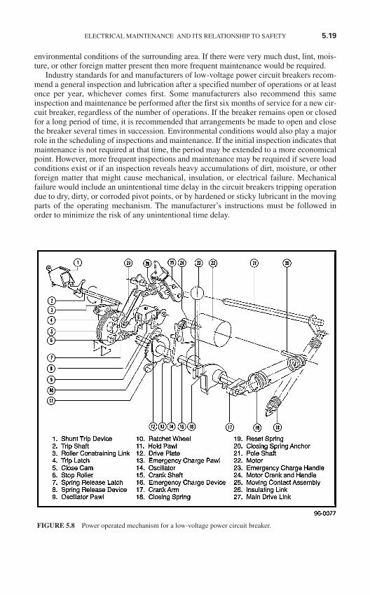
environmental conditions of the surrounding area. If there were very much dust, lint, mois-ture, or other foreign matter present then more frequent maintenance would be required.
Industry standards for and manufacturers of low-voltage power circuit breakers recom-mend a general inspection and lubrication after a specified number of operations or at leastonce per year, whichever comes first. Some manufacturers also recommend this sameinspection and maintenance be performed after the first six months of service for a new cir-cuit breaker, regardless of the number of operations. If the breaker remains open or closedfor a long period of time, it is recommended that arrangements be made to open and closethe breaker several times in succession. Environmental conditions would also play a majorrole in the scheduling of inspections and maintenance. If the initial inspection indicates thatmaintenance is not required at that time, the period may be extended to a more economicalpoint. However, more frequent inspections and maintenance may be required if severe loadconditions exist or if an inspection reveals heavy accumulations of dirt, moisture, or otherforeign matter that might cause mechanical, insulation, or electrical failure. Mechanicalfailure would include an unintentional time delay in the circuit breakers tripping operationdue to dry, dirty, or corroded pivot points, or by hardened or sticky lubricant in the movingparts of the operating mechanism. The manufacturer’s instructions must be followed inorder to minimize the risk of any unintentional time delay.
ELECTRICAL MAINTENANCE AND ITS RELATIONSHIP TO SAFETY 5.19
FIGURE 5.8 Power operated mechanism for a low-voltage power circuit breaker.
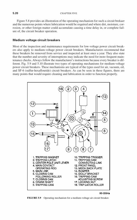
Figure 5.8 provides an illustration of the operating mechanism for such a circuit brekaerand the numerous points where lubrication would be required and where dirt, moisture, cor-rosion, or other foreign matter could accumulate causing a time delay in, or complete fail-ure of, the circuit breaker operation.
Medium voltage circuit breakers
Most of the inspection and maintenance requirements for low-voltage power circuit break-ers also apply to medium-voltage power circuit breakers. Manufacturers recommend thatthese breakers be removed from service and inspected at least once a year. They also statethat the number and severity of interruptions may indicate the need for more frequent main-tenance checks. Always follow the manufacturer’s instructions because every breaker is dif-ferent. Fig. 5.9 and 5.10 illustrate two types of operating mechanisms for medium-voltagepower circuit breakers. These mechanisms are typical of the types used for air, vacuum, oil,and SF-6 (sulfur-hexaflouride) circuit breakers. As can be seen in these figures, there aremany points that would require cleaning and lubrication in order to function properly.
5.20 CHAPTER FIVE
FIGURE 5.9 Operating mechanism for a medium-voltage air circuit breaker.
Protective Relays
Relays must continuously monitor complex power circuit conditions, such as current andvoltage magnitudes, phase angle relationships, direction of power flow, and frequency.When an intolerable circuit condition, such as a short circuit (or fault) is detected, the relayresponds and closes its contacts, and the abnormal portion of the circuit is de-energized viathe circuit breaker. The ultimate goal of protective relaying is to disconnect a faulty systemelement as quickly as possible. Sensitivity and selectivity are essential to ensure that theproper circuit breakers are tripped at the proper speed to clear the fault, minimize damageto equipment, and to reduce the hazards to personnel.
A clear understanding of the possible causes of primary relaying failure is necessary fora better appreciation of the practices involved in backup relaying. One of several things mayhappen to prevent primary relaying from disconnecting a power system fault:
Current or voltage supplies to the relays are incorrect. DC tripping voltage supply is low or absent. Protective relay malfunctions. Tripping circuit or breaker mechanism hangs up.
There are two groups of protective relays: primary and backup. Primary relaying is theso-called first line of defense, and backup relaying is sometimes considered to be a sub-ordinate type of protection. Many companies, however, prefer to supply two lines of relay-ing and do not think of them as primary and backup. Figure 5.11 shows the zones ofprotection for a primary relay system. Circuit breakers are found in the connections to
ELECTRICAL MAINTENANCE AND ITS RELATIONSHIP TO SAFETY 5.21
FIGURE 5.10 Solenoid operated mechanism for a medium-voltage circuit breaker.
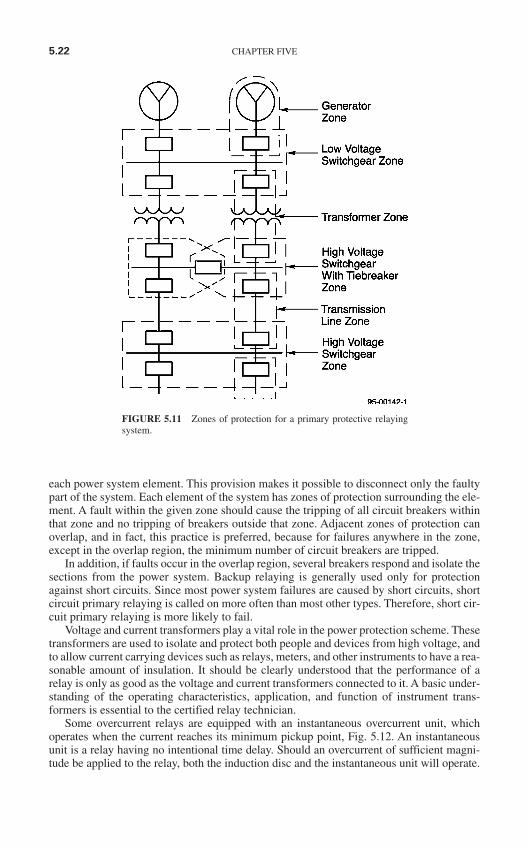
each power system element. This provision makes it possible to disconnect only the faultypart of the system. Each element of the system has zones of protection surrounding the ele-ment. A fault within the given zone should cause the tripping of all circuit breakers withinthat zone and no tripping of breakers outside that zone. Adjacent zones of protection canoverlap, and in fact, this practice is preferred, because for failures anywhere in the zone,except in the overlap region, the minimum number of circuit breakers are tripped.
In addition, if faults occur in the overlap region, several breakers respond and isolate thesections from the power system. Backup relaying is generally used only for protectionagainst short circuits. Since most power system failures are caused by short circuits, shortcircuit primary relaying is called on more often than most other types. Therefore, short cir-cuit primary relaying is more likely to fail.
Voltage and current transformers play a vital role in the power protection scheme. Thesetransformers are used to isolate and protect both people and devices from high voltage, andto allow current carrying devices such as relays, meters, and other instruments to have a rea-sonable amount of insulation. It should be clearly understood that the performance of arelay is only as good as the voltage and current transformers connected to it. A basic under-standing of the operating characteristics, application, and function of instrument trans-formers is essential to the certified relay technician.
Some overcurrent relays are equipped with an instantaneous overcurrent unit, whichoperates when the current reaches its minimum pickup point, Fig. 5.12. An instantaneousunit is a relay having no intentional time delay. Should an overcurrent of sufficient magni-tude be applied to the relay, both the induction disc and the instantaneous unit will operate.
5.22 CHAPTER FIVE
FIGURE 5.11 Zones of protection for a primary protective relayingsystem.
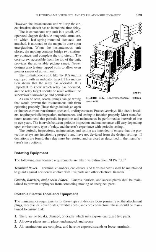
However, the instantaneous unit will trip the cir-cuit breaker, since it has no intentional time delay.
The instantaneous trip unit is a small, AC-operated clapper device. A magnetic armature,to which leaf-spring-mounted contacts areattached, is attracted to the magnetic core uponenergization. When the instantaneous unitcloses, the moving contacts bridge two station-ary contacts and complete the trip circuit. Thecore screw, accessible from the top of the unit,provides the adjustable pickup range. Newerdesigns also feature tapped coils to allow evengreater ranges of adjustment.
The instantaneous unit, like the ICS unit, isequipped with an indicator target. This indica-tion shows that the relay has operated. It isimportant to know which relay has operated,and no relay target should be reset without thesupervisor’s knowledge and permission.
As can be seen, several things can go wrongthat would prevent the instantaneous unit fromoperating properly. These things include an openor shunted current transformer, open coil, or dirty contacts. Protective relays, like circuit break-ers, require periodic inspection, maintenance, and testing to function properly. Most manufac-turers recommend that periodic inspections and maintenance be performed at intervals of oneto two years. The intervals between periodic inspection and maintenance will vary dependingupon environment, type of relay, and the user’s experience with periodic testing.
The periodic inspections, maintenance, and testing are intended to ensure that the pro-tective relays are functioning properly and have not deviated from the design settings. Ifdeviations are found, the relay must be retested and serviced as described in the manufac-turer’s instructions.
Rotating Equipment
The following maintenance requirements are taken verbatim from NFPA 70E.3
Terminal Boxes. Terminal chambers, enclosures, and terminal boxes shall be maintainedto guard against accidental contact with live parts and other electrical hazards.
Guards, Barriers, and Access Plates. Guards, barriers, and access plates shall be main-tained to prevent employees from contacting moving or energized parts.
Portable Electric Tools and Equipment
The maintenance requirements for these types of devices focus primarily on the attachmentplugs, receptacles, cover plates, flexible cords, and cord connectors. These should be main-tained to ensure that:
1. There are no breaks, damage, or cracks which may expose energized live parts.
2. All cover plates are in place, undamaged, and secure.
3. All terminations are complete, and have no exposed strands or loose terminals.
ELECTRICAL MAINTENANCE AND ITS RELATIONSHIP TO SAFETY 5.23
FIGURE 5.12 Electromechanical instanta-neous unit.
4. That all pins and connectors in the plugs are intact, in place, and firm.
5. That the polarity is correct, that is, the hot, neutral, and ground leads are all connectedto their correct terminations.
Personal Safety and Protective Equipment
The maintenance, inspection, and testing requirements for this type of equipment are allcovered in detail in Chap. 3 of this handbook.
CONCLUSION
Electrical maintenance is critical to the safety of all personnel who must work in the vicin-ity of electrical equipment. Whether justified on a safety or an economic basis, all facilitiesshould have a comprehensive electrical maintenance program.
Although the topic is too detailed for complete coverage in this handbook, there are anumber of excellent publications and consultants available to help with the establishmentand continuation of a good electrical maintenance program.
REFERENCES
1. International Electrical Testing Association (NETA), Maintenance Testing Specifications forElectrical Power Distribution Equipment and Systems, Morrison, CO, 2001.
2. NFPA 70B, Recommended Practice for Electrical Equipment Maintenance, National FireProtection Association, Quincy, MA, 2002.
3. NFPA 70E, Standard for Electrical Safety Requirements for Employee Workplaces, National FireProtection Association, Quincy, MA, 2004.
4. NFPA 70, National Electrical Code, National Fire Protection Association, Quincy, MA, 2005.5. F.S. Nowlan and H.F. Heap, Reliability-Centered Maintenance, United Airlines, for Office of
Assistant Secretary of Defense, Washington, D.C., December 29, 1978.6. John Cadick, The Eight Step Maintenance Program, Cadick Corporation, Dallas, Texas, 2000–2005.7. National Equipment Manufacturer's Association (NEMA), Vince A. Baclawski, Power Distribution
Products, NEMA, EC&M magazine, p. 10, January 1995.
5.24 CHAPTER FIVE
REGULATORY AND LEGALSAFETY REQUIREMENTS
AND STANDARDS
INTRODUCTION
The modern trend in electrical safety is toward more and more individual responsibility asemployees are being held increasingly responsible for their actions. For individuals to suc-cessfully fulfill their responsibilities, they must be aware of the rules that apply to their per-formance. This means that company safety rules; national and international standards; andlocal, state, and federal laws must be part of an employee’s knowledge base.
At the same time, the Occupational Safety and Health Administration (OSHA) has becomeincreasingly severe in its enforcement of safety standards. Employers must redouble theirefforts to interpret and implement the best possible electrical safety program. To do this,employers must become familiar with all of the various standards—both regulatory and con-sensus—so that they can comply with them.
Electrical safety standards and/or requirements are produced by a variety of organizations.Some of the standards are voluntary and some are local or federal law. Whether voluntary ormandatory, these standards provide guidance for the proper way to work on or around electricenergy. Much of the material covered in other parts of this handbook is drawn from the stan-dards that will be covered in this chapter.
Since electrical standards are periodically reviewed and updated, the information includedin this chapter is necessarily general. Always refer to the most recent edition of each of thesestandards when current information is required. Note that not all standards are covered in thischapter. The reader should refer to industry-specific literature for their own industries.
Because of the very critical role that standards organizations play, coverage of them is alsoincluded in this chapter. The organizational structure, the standard-making procedure, and thehistorical development of each standards organization are covered.
THE REGULATORY BODIES
The American National Standards Institute (ANSI)
Overview. Founded in 1918, the ANSI is a private, nonprofit, membership organization. TheANSI coordinates the United States voluntary consensus standards systems and approvesAmerican national standards. The ANSI membership includes over 1000 companies;hundreds of professional, technical, trade, labor, and consumer organizations; and dozens of
CHAPTER 6
6.1
Copyright © 2006 by The McGraw-Hill Companies, Inc. Click here for terms of use.
government agencies. The ANSI’s primary purpose is to ensure that a single set of noncon-flicting American national standards is developed by ANSI-accredited standards developersand that all interests concerned have the opportunity to participate in the development process.Since all interested parties are able to participate in the standard-making process, ANSI stan-dards are true consensus standards.
Functions. The ANSI serves five extremely important functions for industry:
Coordinates voluntary standards activities. The ANSI assists standards developers andstandards users from the private sector and government to reach agreement on the need forstandards and to establish priorities. It accredits qualified organizations to develop standards,helps them avoid duplication of effort, and offers a neutral forum for resolving differences.The ANSI’s Executive Standards Council and standards boards spearhead this function.
Approves American national standards. The ANSI administers the only recognized USsystem for establishing American national standards. The ANSI approval procedures ensurethat any interested party can participate in a standard’s development or comment on its pro-visions. These requirements for due process guarantee that American national standardsearn high levels of confidence and credibility and achieve broad acceptance.
Represents US interests in international standardization. The ANSI is the sole US repre-sentative to two of the major, nontreaty standards organizations: the International Organiza-tion for Standardization (ISO) and the International Electrotechnical Commission (IEC).The ISO, founded in 1946, develops, coordinates, and promotes international standards withnational standards organizations from over 70 countries around the world. The IEC, foundedin 1906, develops and promotes electrotechnical standards with national committees fromover 40 countries. The ANSI participates in almost the entire technical program of bothorganizations and administers many key committees and subgroups.
Provides information on and access to world standards. The ANSI maintains copies ofapproved and draft American national standards, ISO and IEC standards, proposals ofregional groups tied to the European Community, and the specifications of 90 national stan-dards organizations that belong to the ISO. These standards are available to interested parties.
Member Companies. The ANSI is a membership organization and draws its principle rev-enue from the company members. Company members help to govern the ANSI by determiningpolicies, procedures, and long-range plans for standards development. They identify commer-cial and industrial needs for standards, both nationally and internationally. Based on theseneeds, they encourage ANSI to initiate new activities for standards development and accelerateimprovement of existing standards.
Standards Developers. Standards developers are primarily national trade, technical, pro-fessional, consumer, and labor organizations. They voluntarily submit standards to the ANSIfor recognition as national consensus standards. Many of these organizations are also mem-bers of the ANSI and are represented on the boards, councils, and committees that help gov-ern the ANSI and coordinate national and international standardization activities.
Government Agencies. The ANSI works with governmental agencies in the same waythey work with other organizations. That is, government agencies are ANSI members, andgovernment representatives serve on ANSI boards and councils.
Coordinating committees, formed with the OSHA and the Consumer Product SafetyCommission, provide forums to discuss activities affecting the voluntary and governmen-tal standards communities.
6.2 CHAPTER SIX
The Institute of Electrical and Electronic Engineers (IEEE)
Overview. The IEEE is the world’s largest professional technical society, with over 350,000members from approximately 150 countries around the world. The American Institute of Elec-trical Engineers (AIEE) was founded in 1884, and the Institute of Radio Engineers (IRE) wasfounded in 1912. These two organizations merged in 1963 to form the IEEE.
The IEEE is a membership society composed of electrical engineers and technicians. Theinterest areas of IEEE members covers the gamut of technical areas including computer engi-neering, biomedical technology, telecommunications, electric power, aerospace, and con-sumer products.
Functions. Among the IEEE’s primary activities are technical publishing, technical con-ferences, and development of technical standards. The IEEE is responsible for approximately30 percent of the world’s published literature in electrotechnology. Ranging from publishedpapers, to textbooks, to technical journals, IEEE literature is typically on the cutting edge oftechnology.
The IEEE is divided into a variety of technical societies with a broad spectrum of tech-nical interests. Primarily through these societies the IEEE holds more than 300 meetingsannually which allow engineers and technicians to exchange information. The IEEE alsodevelops and publishes voluntary technical standards which regulate a variety of electricaltechnical activities.
National Fire Protection Association (NFPA)
Overview. The NFPA was founded in 1896 for the express purpose of protecting people,property, and the environment from the effects of fire. To fulfill its purposes, the NFPAfocuses its efforts into intensive technical activities and extensive educational programs. TheNFPA is a nonprofit organization and has a membership of approximately 67,000 from 85nations.
The NFPA has an extremely well recognized and respected set of voluntary consensuscodes and standards. These codes and standards, hundreds of them, are used extensivelyby the NFPA’s network of fire service, industrial, health care, building code, and otherprofessional members. The NFPA technical committees are staffed by thousands of vol-unteers from a balanced cross section of affected interests.
The NFPA is responsible for the National Electrical Code, a document which is one ofthe most recognized electrical safety standards in the world.
Functions. The NFPA is involved in a wide variety of functions and activities.
The Learn Not to Burn Curriculum is for children from kindergarten through eighthgrade. This program, introduced by the NFPA in 1979, has a documented record of sav-ing hundreds of lives because of lessons remembered by children.
Fire Prevention Week is observed each year on October 9—the anniversary of the greatChicago fire of 1871. The first Fire Prevention Week was proclaimed by President War-ren G. Harding in 1922. The NFPA has sponsored the week ever since.
The NFPA maintains one of the major fire safety literature collections. NFPA conducts investigations of major fires. These fires are investigated as a result of
their technical or educational interest.
REGULATORY AND LEGAL SAFETY REQUIREMENTS AND STANDARDS 6.3
The NFPA Standards-Making System. The NFPA and its standards-making effortsgrew from a meeting of a small group in Boston in 1895. That group was meeting to dis-cuss sprinkler installation standards in the Boston area. From that initial standard hasgrown the NFPA standards-making system of today.
The standards-making procedure starts with the submission of a request for a new stan-dard by an interested party. The request is reviewed by the NFPA Standards Council whopublishes an announcement in the membership newsletter, Fire News. The announcementacknowledges the request for a standard and asks for comments on the need for the project,information on organizations that may be active in the subject matter of the proposed pro-ject, a listing of resource material that is available, and an indication of who would be will-ing to participate in the project if it is approved.
If the council determines a need for the proposed project, it either assigns the project to anexisting technical committee or a new committee whose membership reflects a fair balance ofconcerned interests. Members of technical committees are appointed by the standards counciland include volunteer experts representing the government, educational institutions, business,insurance companies, industry, and consumers. Each committee member is classified accord-ing to his or her interest, and each committee is structured so that no more than one-third of themembership is from a single interest.
Once the technical committee has been established, the NFPA issues public noticesannouncing the committee’s next meeting date and calling for specific proposals from inter-ested persons. Anyone may submit a proposal for text to be included in a new document oradded to an existing document. The committee then meets to consider all proposals receivedand drafts a proposed document or amendments to an existing document. Submitters mayaddress the committee on their proposals at the meeting. Letter ballot approval by at least two-thirds of all committee members eligible to vote is required to approve a proposal for inclusionin the document.
After suitable procedures to allow for objections, and a vote of the membership, thedocument is presented to the standards council for final issuance. If the standards councilissues the standard, based on the vote of the membership, it is published in pamphlet formand is also included in the appropriate volume of NFPA’s National Fire Codes. If the stan-dard is to be an American national standard, it is submitted to the ANSI.
American Society for Testing and Materials (ASTM)
Overview. The ASTM was organized in 1898 and has grown to an extremely large,voluntary standards development organization. The organization develops standardsin a variety of areas including materials, products, systems, and services. The ASTMhas over 129 standards-writing committees which write standards in such diverseareas as metals, paints, plastics, textiles, petroleum, construction, energy, the environ-ment, consumer products, medical services and devices, computerized systems, andelectronics.
The ASTM headquarters has no technical research or testing facilities because suchwork is done voluntarily by over 32,000 technically qualified ASTM members locatedthroughout the world. The ASTM publishes approximately 10,000 standards each year inthe 73 volumes of the Annual Book of ASTM Standards.
Function. The ASTM develops six principal types of full consensus standards including
Standard test method. This is a definitive procedure for the identification, measure-ment, and evaluation of one or more qualities, characteristics, or properties of a material,product, system, or service that produces a test result.
6.4 CHAPTER SIX
Standard specification. This is a precise statement of a set of requirements to be satis-fied by a material, product, system, or service that also indicates the procedures for deter-mining whether each of the requirements is satisfied.
Standard practice. A definitive procedure for performing one or more specific opera-tions or functions that does not produce a test result.
Standard terminology. A document comprising terms, definitions, descriptions of terms,and explanations of symbols, abbreviations, or acronyms.
Standard guide. A series of options or instructions that do not recommend a specificcourse of action.
Standard classification. A systematic arrangement or division of materials, products,systems, or services into groups based on similar characteristics such as origin, compo-sition, properties, or use.
The ASTM Standards-Making System. Like most consensus standards organizations, theASTM begins its standards-making activities when a need is identified. Task group membersprepare a draft standard, which is reviewed by its parent subcommittee through a letter ballot.After the subcommittee approves the document, it is submitted to a main committee letter bal-lot. Once approved at the main committee level, the document is submitted for balloting to theASTM. All negative votes cast during the balloting process, which must include a writtenexplanation of the voter’s objections, must be fully considered before the document can besubmitted to the next level in the process. Final approval of a standard depends on concurrenceby the ASTM Committee on Standards that proper procedures were followed and due processwas achieved.
American Society of Safety Engineers (ASSE)
Overview. The ASSE was founded in 1911. It is a membership organization composed ofsafety professionals throughout the world. The 33,000 members manage, supervise, andconsult on safety, health, and environmental issues in industry, government, and education.
The ASSE’s mission is to enhance the status and promote the advancement of the safetyprofession and to foster the technical, scientific, managerial, and ethical knowledge, skills,and competency of safety professionals.
The ASSE has 32,600 members who manage, supervise, and consult on safety, health, andenvironmental issues in industry, insurance, government, and education. Safety professionalshelp prevent accidents, injuries, and occupational diseases; create safe environments for workand leisure; and develop safe products for use in all areas of human activity.
ASSE is guided by a 15-member board of directors, which consists of 8 regional vice pres-idents; 3 council vice presidents; and the Society president, president-elect, senior vice presi-dent, vice president of finance, and executive director. The board is guided in decision makingby five standing committees and four councils.
Function. The ASSE meets its responsibilities by providing continuing education, mem-bership services, standards-making activities, peer recognition awards, marketing, andsafety public relations.
Continuing Education. The ASSE sponsors professional development seminars, publi-cations, conference proceedings, training packages, computer resources, and audiovisual aids.
Membership Services. The ASSE provides a variety of related membership servicesincluding professional development seminars, technical publications, and leadershipconferences.
REGULATORY AND LEGAL SAFETY REQUIREMENTS AND STANDARDS 6.5

ASSE Standards. The ASSE serves as the secretariat for a number of American nationalstandards. Those of special interest to electrical safety include Eye and Face Protection(Z87.1), Safety Requirements for Confined Spaces (Z117.1), and Safety Requirements forLadders (A14.1 to A14.8).
The Occupational Safety and Health Administration (OSHA)
Standards issued by the OSHA differ from other standards in one very significant aspect—they are enforceable under federal law. The following sections outline some of the moreimportant facts about the OSHA and its standards. You should contact your local OSHAoffice if more detailed information is required.
The Occupational Safety and Health Act of 1970. Part of the material in the following sec-tions was drawn from the government publication OSHA 2056 entitled All About OSHA.
In 1970, the United States was faced with the following statistics:
Job-related accidents accounted for more than 14,000 worker deaths per year. Nearly 2.5 million workers were disabled. Ten times as many person-days were lost from job-related disabilities than from strikes. Estimated new cases of occupational diseases totaled 300,000.
To address these problems, Congress passed the Occupational Safety and Health Act of1970 (the Act). The execution of the Act is the responsibility of the Department of Laborunder the Secretary of Labor. The Act created the OSHA to continually create, review, andredefine specific standards and practices.
Coverage under the Act extends to all employers and their employees in the 50 states,the District of Columbia, Puerto Rico, and all other territories under federal governmentjurisdiction. The Act exempts three important categories:
Self-employed persons Farms at which only immediate members of the farm employer’s family are employed Working conditions regulated by other federal agencies under other federal statutes
The Act has special provisions for some employees and employers. State and localgovernments and the federal government have special consideration under the Act.Employers and employees should contact their local OSHA office to determine what theirobligations are.
The OSHA’s Purpose. The OSHA is the administration that is given the principle responsi-bilities for implementation of the Act. A few of the OSHA’s responsibilities include
Encourage employers and employees to reduce workplace hazards and to implement newor improved existing safety and health programs.
Establish separate but dependent responsibilities and rights for employers and employ-ees with respect to achieving safe and healthful working conditions.
Set and enforce mandatory occupational safety and health standards applicable to busi-nesses affecting interstate commerce.
Maintain a reporting and record-keeping system to monitor job-related illnesses andinjuries.
6.6 CHAPTER SIX
Establish training programs to increase the number and competence of occupationalsafety and health personnel.
Provide for the development, analysis, evaluation, and approval of state occupationalsafety and health programs.
The OSHA is a branch of the Department of Labor and is responsible to the Secretary ofLabor.
Responsibilities and Rights of Employers. Employers have the principal responsibilityto guarantee that all OSHA rules and regulations are properly and promptly administeredin the workplace. Employers who do not carry out their responsibilities can be heavilyfined. The following list identifies some of the more significant employer responsibilities.Employers must
Meet their general responsibility to provide a workplace free from recognized hazardsthat are causing or are likely to cause death or serious physical harm to employees.
Be familiar with mandatory OSHA standards and make copies available to employeesfor review upon request.
Inform all employees about the OSHA. Examine workplace conditions to make sure they conform to applicable standards. Minimize or reduce hazards. Make sure that employees have, use, and maintain safe tools and equipment. These tools
and equipment include appropriate personal protective equipment such as flash suits,rubber gloves, and hard hats.
Use color codes, posters, labels, or signs when needed to warn employees of potentialhazards.
Establish or update operating procedures and communicate them so that employees fol-low safety and health requirements.
Provide medical examinations when required by OSHA standards. Provide training required by OSHA standards. For example, the Safety Related Work
Practices Rule and the Control of Hazardous Energy Source Rule both require a certainamount of employee training for complete implementation.
Report to the nearest OSHA office within 48 h any fatal accident or one that results in thehospitalization of five or more employees.
Keep OSHA-required records of work-related injuries and illnesses, and post a copy ofthe totals from the last page of OSHA No. 200 during the entire month of February ofeach year. Note: This applies only to employers with 11 or more employees and employ-ers who are chosen by the Bureau of Labor Statistics.
Post the OSHA poster (OSHA 2203) informing employees of their rights and responsibili-ties at a prominent location in the workplace. In states with OSHA-approved state job safetyand health programs, the state’s equivalent poster and/or the OSHA poster may be required.
Provide employees, former employees, and their representatives access to the Log andSummary of Occupational Injuries and Illnesses (OSHA No. 200) at a reasonable timeand in a reasonable manner.
Provide access to employee medical records and exposure records to employees or theirauthorized representatives.
Cooperate with the OSHA compliance officer by furnishing names of authorized employeerepresentatives who may be asked to accompany the compliance officer during an inspection.
REGULATORY AND LEGAL SAFETY REQUIREMENTS AND STANDARDS 6.7

(If none, the compliance officer will consult with a reasonable number of employees con-cerning safety and health in the workplace.)
Not discriminate against employees who properly exercise their rights under the Act. Put OSHA citations at or near the work site involved. Abate cited violations within the prescribed period.
Employers also have rights under the OSHA act. The following items list some of themore important employer’s rights. Employers have the right to
Seek advice and off-site consultation as needed by writing, calling, or visiting the nearestOSHA office. The OSHA will not inspect merely because an employer requests assistance.
Be active in their industry association’s involvement in safety and health. Request and receive proper identification of the OSHA compliance officer prior to
inspection. Be advised by the compliance officer of the reason for an inspection. Have an opening and closing conference with the compliance officer. Accompany the compliance officer on the inspection. File a Notice of Contest with the OSHA area director within 15 working days or receipt
of a notice of citation and proposed penalty. Apply to the OSHA for a temporary variance from a standard if unable to comply
because of the unavailability of materials, equipment, or personnel needed to make nec-essary changes within the required time.
Apply to the OSHA for a permanent variance from a standard if they can furnish proofthat their facilities or method of operation provide employee protection at least as effec-tive as that required by the standard.
Take an active role in developing safety and health standards through participation inOSHA standards and advisory committees, through nationally recognized standards-setting organizations, and through evidence and views presented in writing or at hearings.
Be assured of the confidentiality of any trade secrets observed by an OSHA complianceofficer during inspection.
Submit a written request to the National Institute of Occupational Safety and Health(NIOSH) for information on whether any substance in your workplace has potentiallytoxic effects in the concentrations being used.
Responsibilities and Rights of Employees. The Act was designed to establish workplacerules and regulations which will enhance the health and safety of employees. Because ofthis, the employers are considered to have principal responsibility for the implementationof OSHA rules. Employees, therefore, are not cited for violations. In spite of this, employ-ees still have responsibilities under the Act. Employees must
Read the OSHA poster at the job site. Comply with all applicable OSHA standards. Follow all employer safety and health rules and regulations, and wear or use prescribed
protective equipment while engaged in work. Report hazardous conditions to the supervisor. Report any job-related injury or illness to the employer. Promptly seek treatment from job-related injuries or illnesses.
6.8 CHAPTER SIX
Cooperate with the OSHA compliance officer conducting an inspection if he or sheinquires about safety and health conditions in your workplace.
Exercise their rights under the Act in a responsible manner.
Employees also have significant rights under the Act. Employees have a right to
Seek safety and health on the job without fear of punishment. Complain to an employer, union, the OSHA, or any other government agency about job
safety and health hazards. File safety or health grievances. Participate on a workplace safety and health committee or in union activities concerning
job safety and health. Participate in OSHA inspections, conferences, hearings, or other OSHA-related activities.
OSHA’S Electrical Safety Standards. OSHA safety standards are published in the Codeof Federal Regulations, Title 29, Subtitle B, Chapter XVII. The OSHA has issued or willissue electrical safety standards in at least four categories:
1. Design and installation safety
2. Safety-related work practices
3. Safety-related maintenance requirements
4. Special equipment
In addition, the OSHA has issued or will issue standards regulating a variety of relatedareas such as Control of Hazardous Energy. Electrical safety standards for general industry arefound in Part 1910, Subpart S, which includes Paragraphs 1910-301 through 1910-399. Elec-trical safety standards for employees in the construction industry are found in Part 1926, Sub-part K, which includes Paragraphs 1926-400 through 1926-449. Table 6.1 identifies thevarious locations for the standards.
Note that by its very nature, Table 6.1 is time-sensitive. Be certain to check the currentedition of the OSHA standard for complete information. These standards can be procuredfrom your local OSHA office. The various OSHA standards will be covered in more detaillater in this chapter.
OSHA Technical Consultation. The OSHA will provide technical support and consulta-tion at no charge. The consultation services are provided by state government agencies oruniversities employing professional safety and health consultants. Although intended forsmaller employers with more hazardous operations, the consultation service is available tocompanies of all sizes.
The technical consultation starts when the employer requests the service and makes a com-mitment to correct any possible violations discovered by the inspector. The complete consul-tation involves six basic steps: the request, the opening conference, the walk-throughinspection, the closing conference, the written report, and the corrective actions. Table 6.2 listsand describes each of these six steps.
Employers are exempted from inspections or fines by OSHA compliance personnel duringthe consultation process. In some cases, if employers can demonstrate that an effective safety andhealth program is in operation, they may be exempted from OSHA general schedule enforce-ment inspections. This exemption does not apply to complaint or accident investigations.
Voluntary Protection Programs. Voluntary protection programs (VPP) (Table 6.3) aredesigned to extend worker protection beyond the minimums required by the OSHA stan-dards. These three programs are designed to
REGULATORY AND LEGAL SAFETY REQUIREMENTS AND STANDARDS 6.9
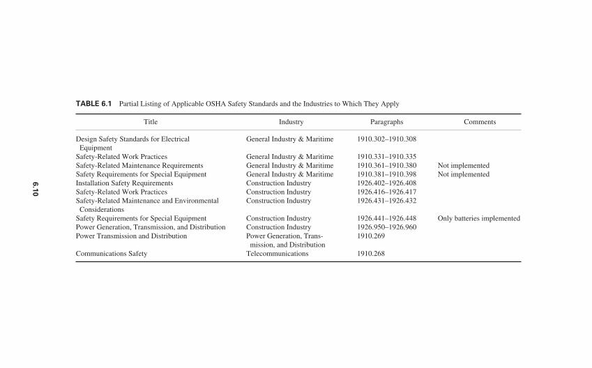
TABLE 6.1 Partial Listing of Applicable OSHA Safety Standards and the Industries to Which They Apply
Title Industry Paragraphs Comments
Design Safety Standards for Electrical General Industry & Maritime 1910.302–1910.308Equipment
Safety-Related Work Practices General Industry & Maritime 1910.331–1910.335Safety-Related Maintenance Requirements General Industry & Maritime 1910.361–1910.380 Not implementedSafety Requirements for Special Equipment General Industry & Maritime 1910.381–1910.398 Not implementedInstallation Safety Requirements Construction Industry 1926.402–1926.408Safety-Related Work Practices Construction Industry 1926.416–1926.417Safety-Related Maintenance and Environmental Construction Industry 1926.431–1926.432
ConsiderationsSafety Requirements for Special Equipment Construction Industry 1926.441–1926.448 Only batteries implementedPower Generation, Transmission, and Distribution Construction Industry 1926.950–1926.960Power Transmission and Distribution Power Generation, Trans- 1910.269
mission, and DistributionCommunications Safety Telecommunications 1910.268
6.1
0
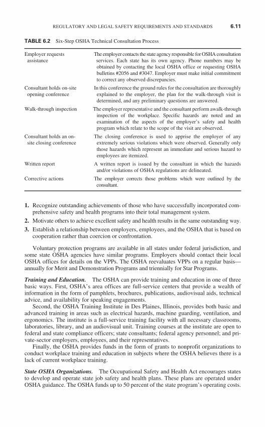
1. Recognize outstanding achievements of those who have successfully incorporated com-prehensive safety and health programs into their total management system.
2. Motivate others to achieve excellent safety and health results in the same outstanding way.
3. Establish a relationship between employers, employees, and the OSHA that is based oncooperation rather than coercion or confrontation.
Voluntary protection programs are available in all states under federal jurisdiction, andsome state OSHA agencies have similar programs. Employers should contact their localOSHA offices for details on the VPPs. The OSHA reevaluates VPPs on a regular basis—annually for Merit and Demonstration Programs and triennially for Star Programs.
Training and Education. The OSHA can provide training and education in one of threebasic ways. First, OSHA’s area offices are full-service centers that provide a wealth ofinformation in the form of pamphlets, brochures, publications, audiovisual aids, technicaladvice, and availability for speaking engagements.
Second, the OSHA Training Institute in Des Plaines, Illinois, provides both basic andadvanced training in areas such as electrical hazards, machine guarding, ventilation, andergonomics. The institute is a full-service training facility with all necessary classrooms,laboratories, library, and an audiovisual unit. Training courses at the institute are open tofederal and state compliance officers; state consultants; federal agency personnel; and pri-vate-sector employers, employees, and their representatives.
Finally, the OSHA provides funds in the form of grants to nonprofit organizations toconduct workplace training and education in subjects where the OSHA believes there is alack of current workplace training.
State OSHA Organizations. The Occupational Safety and Health Act encourages statesto develop and operate state job safety and health plans. These plans are operated underOSHA guidance. The OSHA funds up to 50 percent of the state program’s operating costs.
REGULATORY AND LEGAL SAFETY REQUIREMENTS AND STANDARDS 6.11
TABLE 6.2 Six-Step OSHA Technical Consultation Process
Employer requests The employer contacts the state agency responsible for OSHA consultation assistance services. Each state has its own agency. Phone numbers may be
obtained by contacting the local OSHA office or requesting OSHAbulletins #2056 and #3047. Employer must make initial commitmentto correct any observed discrepancies.
Consultant holds on-site In this conference the ground rules for the consultation are thoroughlyopening conference explained to the employer, the plan for the walk-through visit is
determined, and any preliminary questions are answered.
Walk-through inspection The employer representative and the consultant perform awalk-throughinspection of the workplace. Specific hazards are noted and anexamination of the aspects of the employer’s safety and healthprogram which relate to the scope of the visit are observed.
Consultant holds an on- The closing conference is used to apprise the employer of any site closing conference extremely serious violations which were observed. Generally only
those hazards which represent an immediate and serious hazard toemployees are itemized.
Written report A written report is issued by the consultant in which the hazardsand/or violations of OSHA regulations are delineated.
Corrective actions The employer corrects those problems which were outlined by theconsultant.
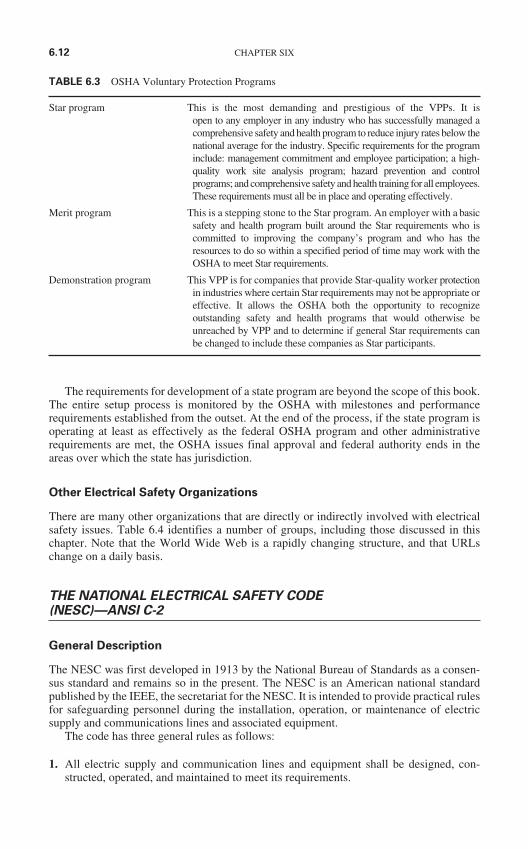
The requirements for development of a state program are beyond the scope of this book.The entire setup process is monitored by the OSHA with milestones and performancerequirements established from the outset. At the end of the process, if the state program isoperating at least as effectively as the federal OSHA program and other administrativerequirements are met, the OSHA issues final approval and federal authority ends in theareas over which the state has jurisdiction.
Other Electrical Safety Organizations
There are many other organizations that are directly or indirectly involved with electricalsafety issues. Table 6.4 identifies a number of groups, including those discussed in thischapter. Note that the World Wide Web is a rapidly changing structure, and that URLschange on a daily basis.
THE NATIONAL ELECTRICAL SAFETY CODE(NESC)—ANSI C-2
General Description
The NESC was first developed in 1913 by the National Bureau of Standards as a consen-sus standard and remains so in the present. The NESC is an American national standardpublished by the IEEE, the secretariat for the NESC. It is intended to provide practical rulesfor safeguarding personnel during the installation, operation, or maintenance of electricsupply and communications lines and associated equipment.
The code has three general rules as follows:
1. All electric supply and communication lines and equipment shall be designed, con-structed, operated, and maintained to meet its requirements.
6.12 CHAPTER SIX
TABLE 6.3 OSHA Voluntary Protection Programs
Star program This is the most demanding and prestigious of the VPPs. It is open to any employer in any industry who has successfully managed acomprehensive safety and health program to reduce injury rates below thenational average for the industry. Specific requirements for the programinclude: management commitment and employee participation; a high-quality work site analysis program; hazard prevention and controlprograms; and comprehensive safety and health training for all employees.These requirements must all be in place and operating effectively.
Merit program This is a stepping stone to the Star program. An employer with a basicsafety and health program built around the Star requirements who iscommitted to improving the company’s program and who has theresources to do so within a specified period of time may work with theOSHA to meet Star requirements.
Demonstration program This VPP is for companies that provide Star-quality worker protectionin industries where certain Star requirements may not be appropriate oreffective. It allows the OSHA both the opportunity to recognizeoutstanding safety and health programs that would otherwise beunreached by VPP and to determine if general Star requirements canbe changed to include these companies as Star participants.
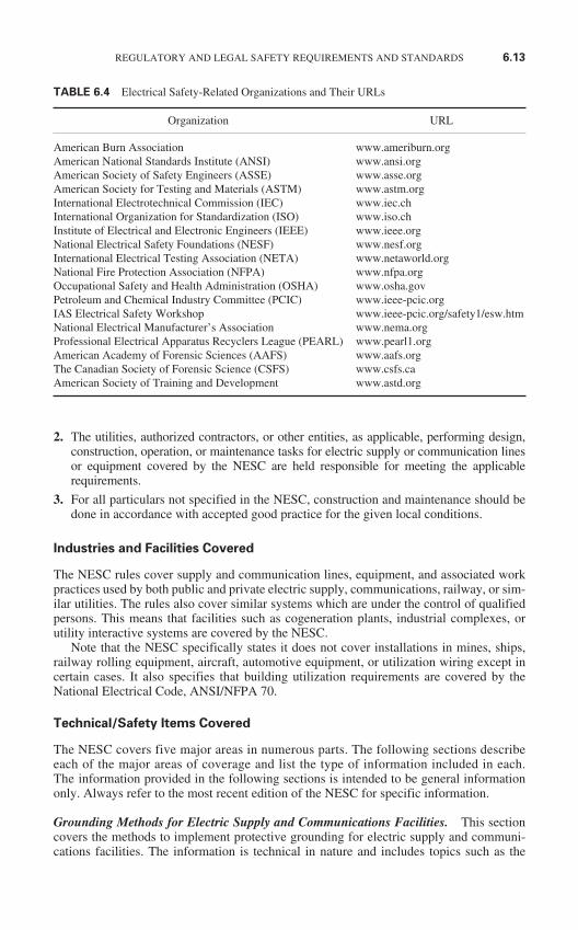
2. The utilities, authorized contractors, or other entities, as applicable, performing design,construction, operation, or maintenance tasks for electric supply or communication linesor equipment covered by the NESC are held responsible for meeting the applicablerequirements.
3. For all particulars not specified in the NESC, construction and maintenance should bedone in accordance with accepted good practice for the given local conditions.
Industries and Facilities Covered
The NESC rules cover supply and communication lines, equipment, and associated workpractices used by both public and private electric supply, communications, railway, or sim-ilar utilities. The rules also cover similar systems which are under the control of qualifiedpersons. This means that facilities such as cogeneration plants, industrial complexes, orutility interactive systems are covered by the NESC.
Note that the NESC specifically states it does not cover installations in mines, ships,railway rolling equipment, aircraft, automotive equipment, or utilization wiring except incertain cases. It also specifies that building utilization requirements are covered by theNational Electrical Code, ANSI/NFPA 70.
Technical/Safety Items Covered
The NESC covers five major areas in numerous parts. The following sections describeeach of the major areas of coverage and list the type of information included in each.The information provided in the following sections is intended to be general informationonly. Always refer to the most recent edition of the NESC for specific information.
Grounding Methods for Electric Supply and Communications Facilities. This sectioncovers the methods to implement protective grounding for electric supply and communi-cations facilities. The information is technical in nature and includes topics such as the
REGULATORY AND LEGAL SAFETY REQUIREMENTS AND STANDARDS 6.13
TABLE 6.4 Electrical Safety-Related Organizations and Their URLs
Organization URL
American Burn Association www.ameriburn.orgAmerican National Standards Institute (ANSI) www.ansi.orgAmerican Society of Safety Engineers (ASSE) www.asse.orgAmerican Society for Testing and Materials (ASTM) www.astm.orgInternational Electrotechnical Commission (IEC) www.iec.chInternational Organization for Standardization (ISO) www.iso.chInstitute of Electrical and Electronic Engineers (IEEE) www.ieee.orgNational Electrical Safety Foundations (NESF) www.nesf.orgInternational Electrical Testing Association (NETA) www.netaworld.orgNational Fire Protection Association (NFPA) www.nfpa.orgOccupational Safety and Health Administration (OSHA) www.osha.govPetroleum and Chemical Industry Committee (PCIC) www.ieee-pcic.orgIAS Electrical Safety Workshop www.ieee-pcic.org/safety1/esw.htmNational Electrical Manufacturer’s Association www.nema.orgProfessional Electrical Apparatus Recyclers League (PEARL) www.pearl1.orgAmerican Academy of Forensic Sciences (AAFS) www.aafs.orgThe Canadian Society of Forensic Science (CSFS) www.csfs.caAmerican Society of Training and Development www.astd.org
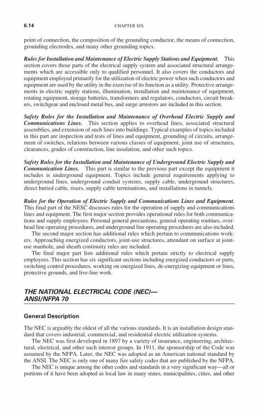
point of connection, the composition of the grounding conductor, the means of connection,grounding electrodes, and many other grounding topics.
Rules for Installation and Maintenance of Electric Supply Stations and Equipment. Thissection covers those parts of the electrical supply system and associated structural arrange-ments which are accessible only to qualified personnel. It also covers the conductors andequipment employed primarily for the utilization of electric power when such conductors andequipment are used by the utility in the exercise of its function as a utility. Protective arrange-ments in electric supply stations, illumination, installation and maintenance of equipment,rotating equipment, storage batteries, transformers and regulators, conductors, circuit break-ers, switchgear and enclosed metal bus, and surge arrestors are included in this section.
Safety Rules for the Installation and Maintenance of Overhead Electric Supply andCommunications Lines. This section applies to overhead lines, associated structuralassemblies, and extension of such lines into buildings. Typical examples of topics includedin this part are inspection and tests of lines and equipment, grounding of circuits, arrange-ment of switches, relations between various classes of equipment, joint use of structures,clearances, grades of construction, line insulation, and other such topics.
Safety Rules for the Installation and Maintenance of Underground Electric Supply andCommunication Lines. This part is similar to the previous part except the equipment itincludes is underground equipment. Topics include general requirements applying tounderground lines, underground conduit systems, supply cable, underground structures,direct buried cable, risers, supply cable terminations, and installations in tunnels.
Rules for the Operation of Electric Supply and Communications Lines and Equipment.This final part of the NESC discusses rules for the operation of supply and communicationslines and equipment. The first major section provides operational rules for both communica-tions and supply employees. Personal general precautions, general operating routines, over-head line operating procedures, and underground line operating procedures are also included.
The second major section has additional rules which pertain to communications work-ers. Approaching energized conductors, joint-use structures, attendant on surface at joint-use manhole, and sheath continuity rules are included.
The final major part lists additional rules which pertain strictly to electrical supplyemployees. This section has six significant sections including energized conductors or parts,switching control procedures, working on energized lines, de-energizing equipment or lines,protective grounds, and live-line work.
THE NATIONAL ELECTRICAL CODE (NEC)—ANSI/NFPA 70
General Description
The NEC is arguably the oldest of all the various standards. It is an installation design stan-dard that covers industrial, commercial, and residential electric utilization systems.
The NEC was first developed in 1897 by a variety of insurance, engineering, architec-tural, electrical, and other such interest groups. In 1911, the sponsorship of the Code wasassumed by the NFPA. Later, the NEC was adopted as an American national standard bythe ANSI. The NEC is only one of many fire safety codes that are published by the NFPA.
The NEC is unique among the other codes and standards in a very significant way—all orportions of it have been adopted as local law in many states, municipalities, cities, and other
6.14 CHAPTER SIX
such areas. Many countries outside of the United States have adopted the NEC in its entirety,or in part, for their national installation codes. Note that both the NFPA and ANSI consider theNEC to be purely an advisory document.
The NEC has become a large document with a wealth of design, installation, and generaltechnical information included. The principal objective of the NEC is to provide standard-ized, technically sound electrical installation standards to help minimize the possibility ofelectric fires.
Industries and Facilities Covered
The NEC covers four basic types of installations. Note that all of these installations are so-called utilization installations as opposed to transmission and distribution.
1. Installations of electric conductors and equipment within or on public and private build-ings or other structures, including mobile homes, recreational vehicles, and floatingbuildings. This section also includes premises wiring for such facilities as yards, carni-val lots, parking lots, and industrial substations.
2. Installations of conductors and equipment that connect to the supply of electricity.
3. Installations of other outside conductors and equipment on the premises.
4. Installations of optical fiber cable.
The NEC also lists several installations to which it does not apply including ships, rail-way rolling stock, underground mine installations, railway generation, communicationsequipment under the control of communications utilities, and certain facilities under thecontrol of electric utilities. The utility facilities that are excluded are the communications,metering, generation, transformation, transmission, and distribution in buildings or sub-stations used specifically for that purpose. The NEC does include utility office buildingsand other such public and commercial structures.
Technical and Safety Items Included
The NEC includes technical specifications and requirements for virtually all electric linesand equipment. The Code has multiple chapters which include rules for wiring and pro-tection, wiring methods and materials, equipment for general use, special occupancies,special equipment, special conditions, and communications systems.
Tables for conductor ampacities are included along with formulas for calculating therequired size and number of conductors for special applications, as well as sizing require-ments for protective devices. Grounding requirements including what, when, and how areincluded. Rules for interrupting capacities and other such information are also included.The NEC has become an engineering reference, an installation guide, a design standard,and a fire safety code all in one volume.
ELECTRICAL EQUIPMENT MAINTENANCE—ANSI/NFPA 70B
General Description
The Electrical Equipment Maintenance document (70B) is a companion publication to theNEC. Many interested parties had been requesting that safety-related maintenance
REGULATORY AND LEGAL SAFETY REQUIREMENTS AND STANDARDS 6.15
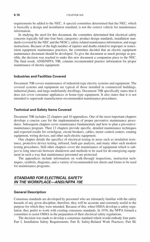
requirements be added to the NEC. A special committee determined that the NEC, whichis basically a design and installation standard, is not the correct vehicle for maintenanceinformation.
In studying the need for this document, the committee determined that electrical safetyconcerns logically fall into four basic categories: product design standards, installation stan-dards (covered by the NEC and the NESC), safety-related maintenance information, and usageinstructions. Because of the high number of injuries and deaths related to improper or nonex-istent equipment maintenance practices, the committee decided that an electric equipmentmaintenance document should be developed. To give the document as much prestige as pos-sible, the decision was reached to make this new document a companion piece to the NEC.The final result, ANSI/NFPA 70B, contains recommended practice information for propermaintenance of electric equipment.
Industries and Facilities Covered
Document 70B covers maintenance of industrial-type electric systems and equipment. Thecovered systems and equipment are typical of those installed in commercial buildings,industrial plants, and large multifamily dwellings. Document 70B specifically states that itdoes not cover consumer appliances or home-type equipment. It also states that it is notintended to supersede manufacturer-recommended maintenance procedures.
Technical and Safety Items Covered
Document 70B includes 22 chapters and 10 appendices. One of the most important chaptersdevelops a concise case for the implementation of proper preventive maintenance proce-dures. Subsequent chapters cover maintenance fundamentals and how to plan a preventive-maintenance program. Then 12 chapters provide specific, detailed maintenance techniquesand expected results for switchgear, circuit breakers, cables, motor control centers, rotatingequipment, wiring devices, and other such electric equipment.
One chapter details the specifics of electrical testing in areas such as insulation resis-tance, protective device testing, infrared, fault-gas analysis, and many other such moderntesting procedures. Still other chapters cover the maintenance of equipment which is sub-ject to long intervals between shutdowns and methods to be used for de-energizing equip-ment in such a way that maintenance personnel are protected.
The appendices include information on walk-through inspections, instruction tech-niques, symbols, diagrams, and a variety of recommended test sheets and forms to be usedfor maintenance programs.
STANDARD FOR ELECTRICAL SAFETYIN THE WORKPLACE—ANSI/NFPA 70E
General Description
Consensus standards are developed by personnel who are intimately familiar with the safetyhazards of any given discipline; therefore, they will be accurate and extremely useful to thepurpose for which they were intended. Because of this, when OSHA develops a safety regu-lation, they prefer to work with existing consensus standards. In 1976, the NFPA formed acommittee to assist OSHA in the preparation of their electrical safety regulations.
The decision was made to develop a consensus standard which would embody four parts:Part I, Installation Safety Requirements; Part II, Safety-Related Work Practices; Part III,
6.16 CHAPTER SIX
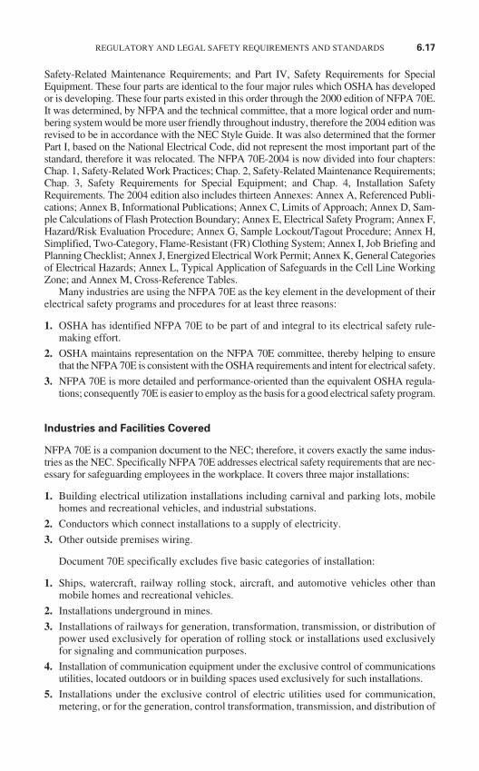
Safety-Related Maintenance Requirements; and Part IV, Safety Requirements for SpecialEquipment. These four parts are identical to the four major rules which OSHA has developedor is developing. These four parts existed in this order through the 2000 edition of NFPA 70E.It was determined, by NFPA and the technical committee, that a more logical order and num-bering system would be more user friendly throughout industry, therefore the 2004 edition wasrevised to be in accordance with the NEC Style Guide. It was also determined that the formerPart I, based on the National Electrical Code, did not represent the most important part of thestandard, therefore it was relocated. The NFPA 70E-2004 is now divided into four chapters:Chap. 1, Safety-Related Work Practices; Chap. 2, Safety-Related Maintenance Requirements;Chap. 3, Safety Requirements for Special Equipment; and Chap. 4, Installation SafetyRequirements. The 2004 edition also includes thirteen Annexes: Annex A, Referenced Publi-cations; Annex B, Informational Publications; Annex C, Limits of Approach; Annex D, Sam-ple Calculations of Flash Protection Boundary; Annex E, Electrical Safety Program; Annex F,Hazard/Risk Evaluation Procedure; Annex G, Sample Lockout/Tagout Procedure; Annex H,Simplified, Two-Category, Flame-Resistant (FR) Clothing System; Annex I, Job Briefing andPlanning Checklist; Annex J, Energized Electrical Work Permit; Annex K, General Categoriesof Electrical Hazards; Annex L, Typical Application of Safeguards in the Cell Line WorkingZone; and Annex M, Cross-Reference Tables.
Many industries are using the NFPA 70E as the key element in the development of theirelectrical safety programs and procedures for at least three reasons:
1. OSHA has identified NFPA 70E to be part of and integral to its electrical safety rule-making effort.
2. OSHA maintains representation on the NFPA 70E committee, thereby helping to ensurethat the NFPA 70E is consistent with the OSHA requirements and intent for electrical safety.
3. NFPA 70E is more detailed and performance-oriented than the equivalent OSHA regula-tions; consequently 70E is easier to employ as the basis for a good electrical safety program.
Industries and Facilities Covered
NFPA 70E is a companion document to the NEC; therefore, it covers exactly the same indus-tries as the NEC. Specifically NFPA 70E addresses electrical safety requirements that are nec-essary for safeguarding employees in the workplace. It covers three major installations:
1. Building electrical utilization installations including carnival and parking lots, mobilehomes and recreational vehicles, and industrial substations.
2. Conductors which connect installations to a supply of electricity.
3. Other outside premises wiring.
Document 70E specifically excludes five basic categories of installation:
1. Ships, watercraft, railway rolling stock, aircraft, and automotive vehicles other thanmobile homes and recreational vehicles.
2. Installations underground in mines.
3. Installations of railways for generation, transformation, transmission, or distribution ofpower used exclusively for operation of rolling stock or installations used exclusivelyfor signaling and communication purposes.
4. Installation of communication equipment under the exclusive control of communicationsutilities, located outdoors or in building spaces used exclusively for such installations.
5. Installations under the exclusive control of electric utilities used for communication,metering, or for the generation, control transformation, transmission, and distribution of
REGULATORY AND LEGAL SAFETY REQUIREMENTS AND STANDARDS 6.17
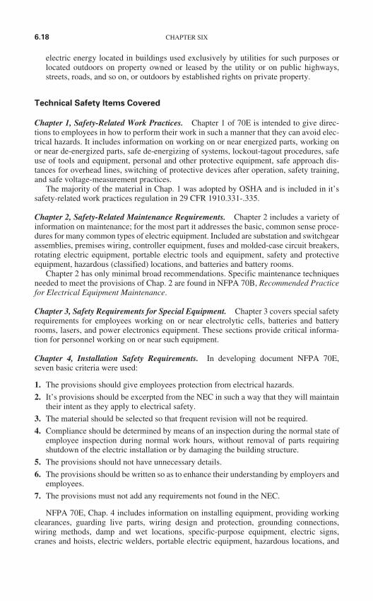
electric energy located in buildings used exclusively by utilities for such purposes orlocated outdoors on property owned or leased by the utility or on public highways,streets, roads, and so on, or outdoors by established rights on private property.
Technical Safety Items Covered
Chapter 1, Safety-Related Work Practices. Chapter 1 of 70E is intended to give direc-tions to employees in how to perform their work in such a manner that they can avoid elec-trical hazards. It includes information on working on or near energized parts, working onor near de-energized parts, safe de-energizing of systems, lockout-tagout procedures, safeuse of tools and equipment, personal and other protective equipment, safe approach dis-tances for overhead lines, switching of protective devices after operation, safety training,and safe voltage-measurement practices.
The majority of the material in Chap. 1 was adopted by OSHA and is included in it’ssafety-related work practices regulation in 29 CFR 1910.331-.335.
Chapter 2, Safety-Related Maintenance Requirements. Chapter 2 includes a variety ofinformation on maintenance; for the most part it addresses the basic, common sense proce-dures for many common types of electric equipment. Included are substation and switchgearassemblies, premises wiring, controller equipment, fuses and molded-case circuit breakers,rotating electric equipment, portable electric tools and equipment, safety and protectiveequipment, hazardous (classified) locations, and batteries and battery rooms.
Chapter 2 has only minimal broad recommendations. Specific maintenance techniquesneeded to meet the provisions of Chap. 2 are found in NFPA 70B, Recommended Practicefor Electrical Equipment Maintenance.
Chapter 3, Safety Requirements for Special Equipment. Chapter 3 covers special safetyrequirements for employees working on or near electrolytic cells, batteries and batteryrooms, lasers, and power electronics equipment. These sections provide critical informa-tion for personnel working on or near such equipment.
Chapter 4, Installation Safety Requirements. In developing document NFPA 70E,seven basic criteria were used:
1. The provisions should give employees protection from electrical hazards.
2. It’s provisions should be excerpted from the NEC in such a way that they will maintaintheir intent as they apply to electrical safety.
3. The material should be selected so that frequent revision will not be required.
4. Compliance should be determined by means of an inspection during the normal state ofemployee inspection during normal work hours, without removal of parts requiringshutdown of the electric installation or by damaging the building structure.
5. The provisions should not have unnecessary details.
6. The provisions should be written so as to enhance their understanding by employers andemployees.
7. The provisions must not add any requirements not found in the NEC.
NFPA 70E, Chap. 4 includes information on installing equipment, providing workingclearances, guarding live parts, wiring design and protection, grounding connections,wiring methods, damp and wet locations, specific-purpose equipment, electric signs,cranes and hoists, electric welders, portable electric equipment, hazardous locations, and
6.18 CHAPTER SIX
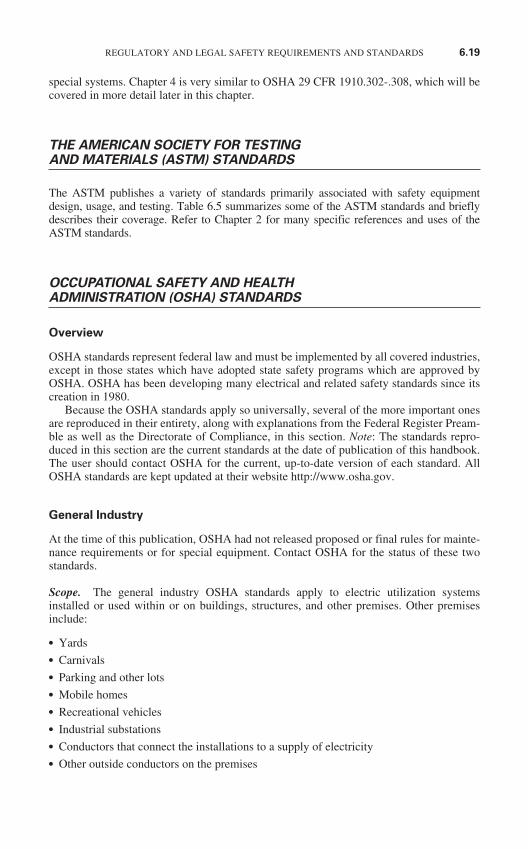
special systems. Chapter 4 is very similar to OSHA 29 CFR 1910.302-.308, which will becovered in more detail later in this chapter.
THE AMERICAN SOCIETY FOR TESTING AND MATERIALS (ASTM) STANDARDS
The ASTM publishes a variety of standards primarily associated with safety equipmentdesign, usage, and testing. Table 6.5 summarizes some of the ASTM standards and brieflydescribes their coverage. Refer to Chapter 2 for many specific references and uses of theASTM standards.
OCCUPATIONAL SAFETY AND HEALTHADMINISTRATION (OSHA) STANDARDS
Overview
OSHA standards represent federal law and must be implemented by all covered industries,except in those states which have adopted state safety programs which are approved byOSHA. OSHA has been developing many electrical and related safety standards since itscreation in 1980.
Because the OSHA standards apply so universally, several of the more important onesare reproduced in their entirety, along with explanations from the Federal Register Pream-ble as well as the Directorate of Compliance, in this section. Note: The standards repro-duced in this section are the current standards at the date of publication of this handbook.The user should contact OSHA for the current, up-to-date version of each standard. AllOSHA standards are kept updated at their website http://www.osha.gov.
General Industry
At the time of this publication, OSHA had not released proposed or final rules for mainte-nance requirements or for special equipment. Contact OSHA for the status of these twostandards.
Scope. The general industry OSHA standards apply to electric utilization systemsinstalled or used within or on buildings, structures, and other premises. Other premisesinclude:
Yards Carnivals Parking and other lots Mobile homes Recreational vehicles Industrial substations Conductors that connect the installations to a supply of electricity Other outside conductors on the premises
REGULATORY AND LEGAL SAFETY REQUIREMENTS AND STANDARDS 6.19
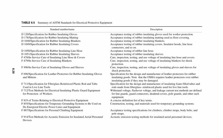
D 120/Specification for Rubber Insulating GlovesD 178/Specification for Rubber Insulating MattingD 1048/Specification for Rubber Insulating BlanketsD 1049/Specification for Rubber Insulating Covers
D 1050/Specification for Rubber Insulating Line HoseD 1051/Specification for Rubber Insulating SleevesF 478/In-Service Care of Insulating Line Hose & CoversF 479/In-Service Care of Insulating Blankets
F 496/In-Service Care of Insulating Gloves and Sleeves
F 696/Specification for Leather Protectors for Rubber Insulating Gloves and Mittens
F 711/Specification for Fiberglass Reinforced Plastic Rod and Tube Used in Live Line Tools
F 712/Test Methods for Electrical Insulating Plastic Guard Equipment for Protection of Workers
F 819 of Terms Relating to Electrical Protective EquipmentF 855/Specifications for Temporary Grounding Systems to Be Used on
De-Energized Electric Power Lines and EquipmentF 887/Specifications for Personal Climbing Equipment
F 914/Test Methods for Acoustic Emission for Insulated Aerial PersonnelDevices
Acceptance testing of rubber insulating gloves used for worker protection.Acceptance testing of rubber insulating matting used as floor covering.Acceptance testing of rubber insulating blankets.Acceptance testing of rubber insulating covers. Insulator hoods, line hose
connectors, and so on.Acceptance testing of rubber line hose.Acceptance testing of rubber insulating sleeves.Care, inspection, testing, and use voltage of insulating line hose and covers.Care, inspection, testing, and use voltage of insulating blankets for shock
protection.Care, inspection, testing, and use voltage of insulating gloves and sleeves for
shock protection.Specification for the design and manufacture of leather protectors for rubber
insulating goods. Note that the OSHA requires leather protectors over rubber insulating goods if they may be damaged.
Specification for the design and manufacture of insulating foam-filled tubes and rods made from fiberglass- reinforced plastic used for live line tools.
Withstand voltage, flashover voltage, and leakage current test methods are definedfor line guards, guard connectors, deadend covers, pole guards, and other such equipment.
A concise definition list of key terms.Construction, testing, and materials used for temporary grounding systems.
Acceptance testing specifications for climbers, climber straps, body belts, and pole straps.
Acoustic emission testing methods for insulated aerial personnel devices.
TABLE 6.5 Summary of ASTM Standards for Electrical Protective Equipment
Standard number/name Description
6.2
0
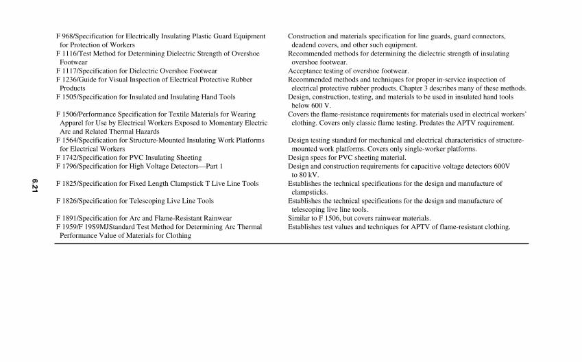
F 968/Specification for Electrically Insulating Plastic Guard Equipment for Protection of Workers
F 1116/Test Method for Determining Dielectric Strength of Overshoe Footwear
F 1117/Specification for Dielectric Overshoe FootwearF 1236/Guide for Visual Inspection of Electrical Protective Rubber
ProductsF 1505/Specification for Insulated and Insulating Hand Tools
F 1506/Performance Specification for Textile Materials for Wearing Apparel for Use by Electrical Workers Exposed to Momentary Electric Arc and Related Thermal Hazards
F 1564/Specification for Structure-Mounted Insulating Work Platforms for Electrical Workers
F 1742/Specification for PVC Insulating SheetingF 1796/Specification for High Voltage Detectors—Part 1
F 1825/Specification for Fixed Length Clampstick T Live Line Tools
F 1826/Specification for Telescoping Live Line Tools
F 1891/Specification for Arc and Flame-Resistant RainwearF 1959/F 19S9MJStandard Test Method for Determining Arc Thermal
Performance Value of Materials for Clothing
Construction and materials specification for line guards, guard connectors, deadend covers, and other such equipment.
Recommended methods for determining the dielectric strength of insulating overshoe footwear.
Acceptance testing of overshoe footwear.Recommended methods and techniques for proper in-service inspection of electrical protective rubber products. Chapter 3 describes many of these methods.
Design, construction, testing, and materials to be used in insulated hand tools below 600 V.
Covers the flame-resistance requirements for materials used in electrical workers’clothing. Covers only classic flame testing. Predates the APTV requirement.
Design testing standard for mechanical and electrical characteristics of structure-mounted work platforms. Covers only single-worker platforms.
Design specs for PVC sheeting material.Design and construction requirements for capacitive voltage detectors 600V
to 80 kV.Establishes the technical specifications for the design and manufacture of
clampsticks.Establishes the technical specifications for the design and manufacture of
telescoping live line tools.Similar to F 1506, but covers rainwear materials.Establishes test values and techniques for APTV of flame-resistant clothing.
6.2
1
OSHA has issued or will issue standards on design safety; electrical safety-related workpractices; lockout/tagout; maintenance-related safety; electric power generation transmis-sion, and distribution; and special equipment safety. All general industry electrical safetystandards are published in Subpart S of Part 1910. Some related standards are published inSubpart J and others in Subpart R. Always refer to the most recent edition. They are repro-duced here for reference only.
Design Safety Standards. The design safety standards cover all utilization systemswhich have been installed or undergone major modification since March 15, 1972. Thesestandards provide design and installation requirements. The design safety standards arefound in the United States Code of Federal Regulations, Title 29, Part 1910, Subpart S,Paragraphs 1910.303 through 1910.308. They are reproduced in Fig. 6.1. Note: explana-tions for these paragraphs are found in the National Electrical Code Handbook.
Safety-Related Work Practices. This OSHA standard covers the procedures required toensure that employees use optimum safety-related procedures when working around ener-gized or potentially energized equipment. It covers a variety of topics including lockout-tagout procedures. Electrical lockout-tagout must follow the methods given in Paragraph1910.333; however, with certain additions, 1910.333 does allow the use of the Control ofHazardous Energy Rule (1910.147).
The Electrical Safety-Related Work Practices Rule is found in the United States Codeof Federal Regulations, Title 29, Part 1910, Subpart S, Paragraphs 1910.331 through1910.335. It is reproduced in this text, along with explanations extracted from the preambleof the Federal Register as well as the Directorate of Compliance, as Fig. 6.2.
Power Generation, Transmission, and Distribution. Employees involved in the opera-tion or maintenance of equipment used for power generation, transmission, or distributionand under the control of an electric utility are covered by this rule. The rule is published inthe United States Code of Federal Regulations, Title 29, Part 1910, Subpart R, Paragraph1910.269. Figure 6.3 is the rule, including explanations extracted from the preamble of theFederal Register.
Control of Hazardous Energy Source (Lockout/Tagout). This rule is not an electricalstandard; in fact, section (a)(1)(ii)(C) specifically excludes electrical hazards. However,the Safety-Related Work Practices Rule, Paragraph 1910.333(b)(2), Note 2 allows the useof the Lockout-Tagout Rule with certain restrictions. Because of its importance, it is repro-duced here, along with explanations from the preamble of the Federal Register, as Fig. 6.4.This rule is published in the United States Code of Federal Regulations, Title 29, Part 1910,Subpart J, Paragraph 1910.147.
Definitions. Figure 6.5 lists the definitions that the OSHA uses in Subpart S of Part 1910.It is published in the United States Code of Federal Regulations, Part 1910, Subpart S,Paragraph 1910.399.
Construction Industry
Scope. The OSHA publishes electrical safety standards for the construction industry intwo subparts. Subpart K applies to construction sites and facilities exclusive of thoseintended exclusively for power generation, transmission, and distribution which is coveredin Subpart V.
6.22 CHAPTER SIX
Installation Safety Requirements. Figure 6.6 is a reproduction of the Installation SafetyRequirements for construction sites. This standard is published in the United States Code ofFederal Regulations, Title 29, Part 1926, Subpart K, Paragraphs 1926.402 through 1926.408.
Safety-Related Work Practices. Because of the nature of electrical exposure of con-struction personnel, this rule is much shorter and less comprehensive than the safety-related work practices rule which applies to the general industry. This standard is publishedin the United States Code of Federal Regulations, Title 29, Part 1926, Sub part K, Para-graphs 1926.416 and 1926.417. Figure 6.7 is a reproduction of the rule.
Safety-Related Maintenance and Environmental Considerations (Construction). Thisstandard is published in the United States Code of Federal Regulations, Title 29, Part1926, Subpart K, Paragraphs 431-432. Figure 6.8 is a reproduction of this standard.
Safety Requirements for Special Equipment (Construction). Batteries are the only appa-ratus included in this rule to date. It is published in the United States Code of Federal Reg-ulations, Part 1926, Subpart K, Paragraph 1926.441. Figure 6.9 reproduces this standard.
Definitions. Figure 6.10 lists the definitions that the OSHA uses in Subpart K of Part1926. It is published in the United States Code of Federal Regulations, Part 1926, SubpartK, Paragraph 1910.449.
REGULATORY AND LEGAL SAFETY REQUIREMENTS AND STANDARDS 6.23
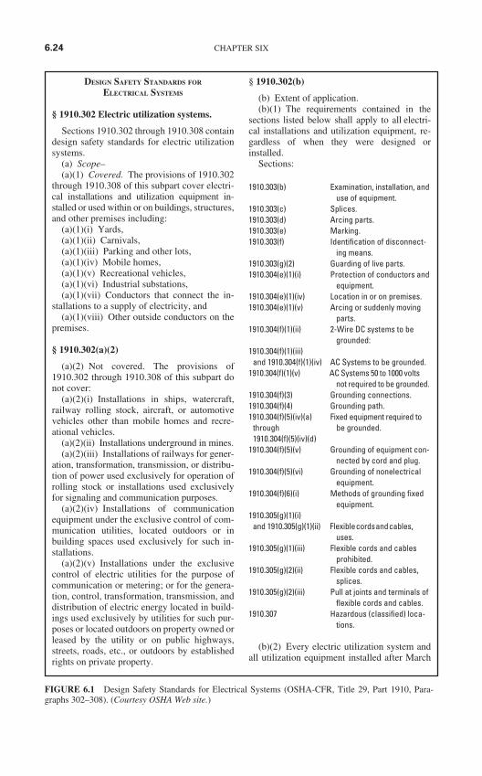
DESIGN SAFETY STANDARDS FOR
ELECTRICAL SYSTEMS
§ 1910.302 Electric utilization systems.
Sections 1910.302 through 1910.308 containdesign safety standards for electric utilizationsystems.
(a) Scope–(a)(1) Covered. The provisions of 1910.302
through 1910.308 of this subpart cover electri-cal installations and utilization equipment in-stalled or used within or on buildings, structures,and other premises including:
(a)(1)(i) Yards,(a)(1)(ii) Carnivals,(a)(1)(iii) Parking and other lots,(a)(1)(iv) Mobile homes,(a)(1)(v) Recreational vehicles,(a)(1)(vi) Industrial substations,(a)(1)(vii) Conductors that connect the in-
stallations to a supply of electricity, and(a)(1)(viii) Other outside conductors on the
premises.
§ 1910.302(a)(2)
(a)(2) Not covered. The provisions of1910.302 through 1910.308 of this subpart donot cover:
(a)(2)(i) Installations in ships, watercraft,railway rolling stock, aircraft, or automotivevehicles other than mobile homes and recre-ational vehicles.
(a)(2)(ii) Installations underground in mines.(a)(2)(iii) Installations of railways for gener-
ation, transformation, transmission, or distribu-tion of power used exclusively for operation ofrolling stock or installations used exclusivelyfor signaling and communication purposes.
(a)(2)(iv) Installations of communicationequipment under the exclusive control of com-munication utilities, located outdoors or inbuilding spaces used exclusively for such in-stallations.
(a)(2)(v) Installations under the exclusivecontrol of electric utilities for the purpose ofcommunication or metering; or for the genera-tion, control, transformation, transmission, anddistribution of electric energy located in build-ings used exclusively by utilities for such pur-poses or located outdoors on property owned orleased by the utility or on public highways,streets, roads, etc., or outdoors by establishedrights on private property.
§ 1910.302(b)
(b) Extent of application.(b)(1) The requirements contained in the
sections listed below shall apply to all electri-cal installations and utilization equipment, re-gardless of when they were designed orinstalled.
Sections:
1910.303(b) Examination, installation, anduse of equipment.
1910.303(c) Splices.1910.303(d) Arcing parts.1910.303(e) Marking.1910.303(f) Identification of disconnect-
ing means.1910.303(g)(2) Guarding of live parts.1910.304(e)(1)(i) Protection of conductors and
equipment.1910.304(e)(1)(iv) Location in or on premises.1910.304(e)(1)(v) Arcing or suddenly moving
parts.1910.304(f)(1)(ii) 2-Wire DC systems to be
grounded:1910.304(f)(1)(iii)
and 1910.304(f)(1)(iv) AC Systems to be grounded.1910.304(f)(1)(v) AC Systems 50 to 1000 volts
not required to be grounded.1910.304(f)(3) Grounding connections.1910.304(f)(4) Grounding path.1910.304(f)(5)(iv)(a) Fixed equipment required to
through be grounded.1910.304(f)(5)(iv)(d)
1910.304(f)(5)(v) Grounding of equipment con-nected by cord and plug.
1910.304(f)(5)(vi) Grounding of nonelectricalequipment.
1910.304(f)(6)(i) Methods of grounding fixedequipment.
1910.305(g)(1)(i)and 1910.305(g)(1)(ii) Flexiblecordsandcables,
uses.1910.305(g)(1)(iii) Flexible cords and cables
prohibited.1910.305(g)(2)(ii) Flexible cords and cables,
splices.1910.305(g)(2)(iii) Pull at joints and terminals of
flexible cords and cables.1910.307 Hazardous (classified) loca-
tions.
(b)(2) Every electric utilization system andall utilization equipment installed after March
6.24 CHAPTER SIX
FIGURE 6.1 Design Safety Standards for Electrical Systems (OSHA-CFR, Title 29, Part 1910, Para-graphs 302–308). (Courtesy OSHA Web site.)
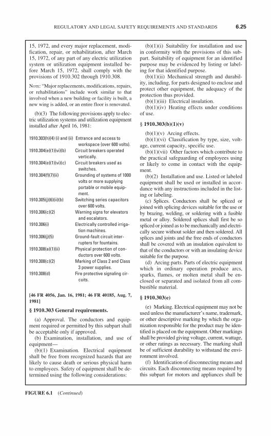
REGULATORY AND LEGAL SAFETY REQUIREMENTS AND STANDARDS 6.25
15, 1972, and every major replacement, modi-fication, repair, or rehabilitation, after March15, 1972, of any part of any electric utilizationsystem or utilization equipment installed be-fore March 15, 1972, shall comply with theprovisions of 1910.302 through 1910.308.
NOTE: “Major replacements, modifications, repairs,or rehabilitations” include work similar to thatinvolved when a new building or facility is built, anew wing is added, or an entire floor is renovated.
(b)(3) The following provisions apply to elec-tric utilization systems and utilization equipmentinstalled after April 16, 1981:
1910.303(h)(4) (i) and (ii) Entrance and access toworkspace (over 600 volts).
1910.304(e)(1)(vi)(b) Circuit breakers operatedvertically.
1910.304(e)(1)(vi)(c) Circuit breakers used asswitches.
1910.304(f)(7)(ii) Grounding of systems of 1000volts or more supplyingportable or mobile equip-ment.
1910.305(j)(6)(ii)(b) Switching series capacitorsover 600 volts.
1910.306(c)(2) Warning signs for elevatorsand escalators.
1910.306(i) Electrically controlled irriga-tion machines.
1910.306(j)(5) Ground-fault circuit inter-rupters for fountains.
1910.308(a)(1)(ii) Physical protection of con-ductors over 600 volts.
1910.308(c)(2) Marking of Class 2 and Class3 power supplies.
1910.308(d) Fire protective signaling cir-cuits.
[46 FR 4056, Jan. 16, 1981; 46 FR 40185, Aug. 7,1981]
§ 1910.303 General requirements.
(a) Approval. The conductors and equip-ment required or permitted by this subpart shallbe acceptable only if approved.
(b) Examination, installation, and use ofequipment—
(b)(1) Examination. Electrical equipmentshall be free from recognized hazards that arelikely to cause death or serious physical harmto employees. Safety of equipment shall be de-termined using the following considerations:
(b)(1)(i) Suitability for installation and usein conformity with the provisions of this sub-part. Suitability of equipment for an identifiedpurpose may be evidenced by listing or label-ing for that identified purpose.
(b)(1)(ii) Mechanical strength and durabil-ity, including, for parts designed to enclose andprotect other equipment, the adequacy of theprotection thus provided.
(b)(1)(iii) Electrical insulation.(b)(1)(iv) Heating effects under conditions
of use.
§ 1910.303(b)(1)(v)
(b)(1)(v) Arcing effects.(b)(1)(vi) Classification by type, size, volt-
age, current capacity, specific use.(b)(1)(vii) Other factors which contribute to
the practical safeguarding of employees usingor likely to come in contact with the equip-ment.
(b)(2) Installation and use. Listed or labeledequipment shall be used or installed in accor-dance with any instructions included in the list-ing or labeling.
(c) Splices. Conductors shall be spliced orjoined with splicing devices suitable for the use orby brazing, welding, or soldering with a fusiblemetal or alloy. Soldered splices shall first be sospliced or joined as to be mechanically and electri-cally secure without solder and then soldered. Allsplices and joints and the free ends of conductorsshall be covered with an insulation equivalent tothat of the conductors or with an insulating devicesuitable for the purpose.
(d) Arcing parts. Parts of electric equipmentwhich in ordinary operation produce arcs,sparks, flames, or molten metal shall be en-closed or separated and isolated from all com-bustible material.
§ 1910.303(e)
(e) Marking. Electrical equipment may not beused unless the manufacturer’s name, trademark,or other descriptive marking by which the orga-nization responsible for the product may be iden-tified is placed on the equipment. Other markingsshall be provided giving voltage, current, wattage,or other ratings as necessary. The marking shallbe of sufficient durability to withstand the envi-ronment involved.
(f) Identification of disconnecting means andcircuits. Each disconnecting means required bythis subpart for motors and appliances shall be
FIGURE 6.1 (Continued)
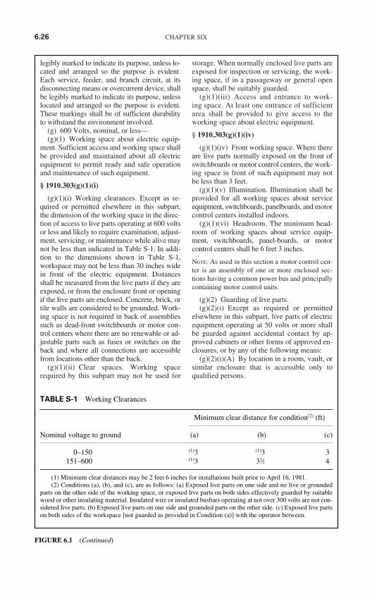
legibly marked to indicate its purpose, unless lo-cated and arranged so the purpose is evident.Each service, feeder, and branch circuit, at itsdisconnecting means or overcurrent device, shallbe legibly marked to indicate its purpose, unlesslocated and arranged so the purpose is evident.These markings shall be of sufficient durabilityto withstand the environment involved.
(g) 600 Volts, nominal, or less—(g)(1) Working space about electric equip-
ment. Sufficient access and working space shallbe provided and maintained about all electricequipment to permit ready and safe operationand maintenance of such equipment.
§ 1910.303(g)(1)(i)
(g)(1)(i) Working clearances. Except as re-quired or permitted elsewhere in this subpart,the dimension of the working space in the direc-tion of access to live parts operating at 600 voltsor less and likely to require examination, adjust-ment, servicing, or maintenance while alive maynot be less than indicated in Table S-1. In addi-tion to the dimensions shown in Table S-1,workspace may not be less than 30 inches widein front of the electric equipment. Distancesshall be measured from the live parts if they areexposed, or from the enclosure front or openingif the live parts are enclosed. Concrete, brick, ortile walls are considered to be grounded. Work-ing space is not required in back of assembliessuch as dead-front switchboards or motor con-trol centers where there are no renewable or ad-justable parts such as fuses or switches on theback and where all connections are accessiblefrom locations other than the back.
(g)(1)(ii) Clear spaces. Working spacerequired by this subpart may not be used for
storage. When normally enclosed live parts areexposed for inspection or servicing, the work-ing space, if in a passageway or general openspace, shall be suitably guarded.
(g)(1)(iii) Access and entrance to work-ing space. At least one entrance of sufficientarea shall be provided to give access to theworking space about electric equipment.
§ 1910.303(g)(1)(iv)
(g)(1)(iv) Front working space. Where thereare live parts normally exposed on the front ofswitchboards or motor control centers, the work-ing space in front of such equipment may notbe less than 3 feet.
(g)(1)(v) Illumination. Illumination shall beprovided for all working spaces about serviceequipment, switchboards, panelboards, and motorcontrol centers installed indoors.
(g)(1)(vi) Headroom. The minimum head-room of working spaces about service equip-ment, switchboards, panel-boards, or motorcontrol centers shall be 6 feet 3 inches.
NOTE: As used in this section a motor control cen-ter is an assembly of one or more enclosed sec-tions having a common power bus and principallycontaining motor control units.
(g)(2) Guarding of live parts.(g)(2)(i) Except as required or permitted
elsewhere in this subpart, live parts of electricequipment operating at 50 volts or more shallbe guarded against accidental contact by ap-proved cabinets or other forms of approved en-closures, or by any of the following means:
(g)(2)(i)(A) By location in a room, vault, orsimilar enclosure that is accessible only toqualified persons.
6.26 CHAPTER SIX
TABLE S-1 Working Clearances
Minimum clear distance for condition(2) (ft)
Nominal voltage to ground (a) (b) (c)
0–150 (1)3 (1)3 3151–600 (1)3 31⁄2 4
(1) Minimum clear distances may be 2 feet 6 inches for installations built prior to April 16, 1981.(2) Conditions (a), (b), and (c), are as follows: (a) Exposed live parts on one side and no live or grounded
parts on the other side of the working space, or exposed live parts on both sides effectively guarded by suitablewood or other insulating material. Insulated wire or insulated busbars operating at not over 300 volts are not con-sidered live parts. (b) Exposed live parts on one side and grounded parts on the other side. (c) Exposed live partson both sides of the workspace [not guarded as provided in Condition (a)] with the operator between.
FIGURE 6.1 (Continued)
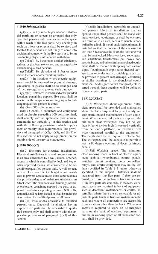
§ 1910.303(g)(2)(i)(B)
(g)(2)(i)(B) By suitable permanent, substan-tial partitions or screens so arranged that onlyqualified persons will have access to the spacewithin reach of the live parts. Any openings insuch partitions or screens shall be so sized andlocated that persons are not likely to come intoaccidental contact with the live parts or to bringconducting objects into contact with them.
(g)(2)(i)(C) By location on a suitable balcony,gallery, or platform so elevated and arranged as toexclude unqualified persons.
(g)(2)(i)(D) By elevation of 8 feet or moreabove the floor or other working surface.
(g)(2)(ii) In locations where electric equip-ment would be exposed to physical damage,enclosures or guards shall be so arranged andof such strength as to prevent such damage.
(g)(2)(iii) Entrances to rooms and other guardedlocations containing exposed live parts shall bemarked with conspicuous warning signs forbid-ding unqualified persons to enter.
(h) Over 600 volts, nominal—(h)(1) General. Conductors and equipment
used on circuits exceeding 600 volts, nominal,shall comply with all applicable provisions ofparagraphs (a) through (g) of this section andwith the following provisions which supple-ment or modify those requirements. The provi-sions of paragraphs (h)(2), (h)(3), and (h)(4) ofthis section do not apply to equipment on thesupply side of the service conductors.
§ 1910.303(h)(2)
(h)(2) Enclosure for electrical installations.Electrical installations in a vault, room, closet orin an area surrounded by a wall, screen, or fence,access to which is controlled by lock and key orother approved means, are considered to be ac-cessible to qualified persons only. A wall, screen,or fence less than 8 feet in height is not consid-ered to prevent access unless it has other featuresthat provide a degree of isolation equivalent to an8 foot fence. The entrances to all buildings, rooms,or enclosures containing exposed live parts or ex-posed conductors operating at over 600 volts,nominal, shall be kept locked or shall be under theobservation of a qualified person at all times.
(h)(2)(i) Installations accessible to qualifiedpersons only. Electrical installations havingexposed live parts shall be accessible to quali-fied persons only and shall comply with the ap-plicable provisions of paragraph (h)(3) of thissection.
(h)(2)(ii) Installations accessible to unquali-fied persons. Electrical installations that areopen to unqualified persons shall be made withmetal-enclosed equipment or shall be enclosedin a vault or in an area, access to which is con-trolled by a lock. If metal-enclosed equipment isinstalled so that the bottom of the enclosure isless than 8 feet above the floor, the door or covershall be kept locked. Metal-enclosed switchgear,unit substations, transformers, pull boxes, con-nection boxes, and other similar associated equip-ment shall be marked with appropriate cautionsigns. If equipment is exposed to physical dam-age from vehicular traffic, suitable guards shallbe provided to prevent such damage. Ventilatingor similar openings in metal-enclosed equip-ment shall be designed so that foreign objects in-serted through these openings will be deflectedfrom energized parts.
§ 1910.303(h)(3)
(h)(3) Workspace about equipment. Suffi-cient space shall be provided and maintainedabout electric equipment to permit ready andsafe operation and maintenance of such equip-ment. Where energized parts are exposed, theminimum clear workspace may not be lessthan 6 feet 6 inches high (measured verticallyfrom the floor or platform), or less than 3 feetwide (measured parallel to the equipment).The depth shall be as required in Table S-2.The workspace shall be adequate to permit atleast a 90-degree opening of doors or hingedpanels.
(h)(3)(i) Working space. The minimumclear working space in front of electric equip-ment such as switchboards, control panels,switches, circuit breakers, motor controllers,relays, and similar equipment may not be lessthan specified in Table S-2 unless otherwisespecified in this subpart. Distances shall bemeasured from the live parts if they are ex-posed, or from the enclosure front or openingif the live parts are enclosed. However, work-ing space is not required in back of equipmentsuch as deadfront switchboards or control as-semblies where there are no renewable or ad-justable parts (such as fuses or switches) on theback and where all connections are accessiblefrom locations other than the back. Where rearaccess is required to work on de-energizedparts on the back of enclosed equipment, aminimum working space of 30 inches horizon-tally shall be provided.
REGULATORY AND LEGAL SAFETY REQUIREMENTS AND STANDARDS 6.27
FIGURE 6.1 (Continued)
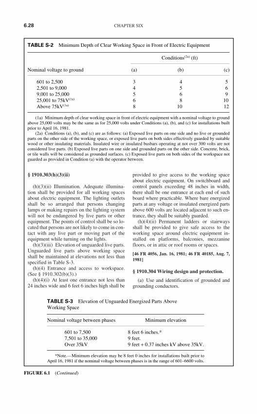
§ 1910.303(h)(3)(ii)
(h)(3)(ii) Illumination. Adequate illumina-tion shall be provided for all working spacesabout electric equipment. The lighting outletsshall be so arranged that persons changinglamps or making repairs on the lighting systemwill not be endangered by live parts or otherequipment. The points of control shall be so lo-cated that persons are not likely to come in con-tact with any live part or moving part of theequipment while turning on the lights.
(h)(3)(iii) Elevation of unguarded live parts.Unguarded live parts above working spaceshall be maintained at elevations not less thanspecified in Table S-3.
(h)(4) Entrance and access to workspace.(See § 1910.302(b)(3).)
(h)(4)(i) At least one entrance not less than24 inches wide and 6 feet 6 inches high shall be
provided to give access to the working spaceabout electric equipment. On switchboard andcontrol panels exceeding 48 inches in width,there shall be one entrance at each end of suchboard where practicable. Where bare energizedparts at any voltage or insulated energized partsabove 600 volts are located adjacent to such en-trance, they shall be suitably guarded.
(h)(4)(ii) Permanent ladders or stairwaysshall be provided to give safe access to theworking space around electric equipment in-stalled on platforms, balconies, mezzaninefloors, or in attic or roof rooms or spaces.
[46 FR 4056, Jan. 16, 1981; 46 FR 40185, Aug. 7,1981]
§ 1910.304 Wiring design and protection.
(a) Use and identification of grounded andgrounding conductors.
6.28 CHAPTER SIX
TABLE S-3 Elevation of Unguarded Energized Parts Above Working Space
Nominal voltage between phases Minimum elevation
601 to 7,500 8 feet 6 inches.*7,501 to 35,000 9 feet.Over 35kV 9 feet + 0.37 inches kV above 35kV.
*Note.—Minimum elevation may be 8 feet 0 inches for installations built prior toApril 16, 1981 if the nominal voltage between phases is in the range of 601–6600 volts.
FIGURE 6.1 (Continued)
TABLE S-2 Minimum Depth of Clear Working Space in Front of Electric Equipment
Conditions(2a) (ft)
Nominal voltage to ground (a) (b) (c)
601 to 2,500 3 4 52,501 to 9,000 4 5 69,001 to 25,000 5 6 925,001 to 75kV(1a) 6 8 10Above 75kV(1a) 8 10 12
(1a) Minimum depth of clear working space in front of electric equipment with a nominal voltage to groundabove 25,000 volts may be the same as for 25,000 volts under Conditions (a), (b), and (c) for installations builtprior to April 16, 1981.
(2a) Conditions (a), (b), and (c) are as follows: (a) Exposed live parts on one side and no live or groundedparts on the other side of the working space, or exposed live parts on both sides effectively guarded by suitablewood or other insulating materials. Insulated wire or insulated busbars operating at not over 300 volts are notconsidered live parts. (b) Exposed live parts on one side and grounded parts on the other side. Concrete, brick,or tile walls will be considered as grounded surfaces. (c) Exposed live parts on both sides of the workspace notguarded as provided in Condition (a) with the operator between.
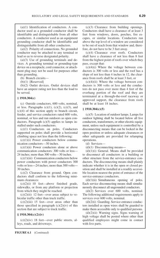
(a)(1) Identification of conductors. A con-ductor used as a grounded conductor shall beidentifiable and distinguishable from all otherconductors. A conductor used as an equipmentgrounding conductor shall be identifiable anddistinguishable from all other conductors.
(a)(2) Polarity of connections. No groundedconductor may be attached to any terminal orlead so as to reverse designated polarity.
(a)(3) Use of grounding terminals and de-vices. A grounding terminal or grounding-typedevice on a receptacle, cord connector, or attach-ment plug may not be used for purposes otherthan grounding.
(b) Branch circuits—(b)(1) [Reserved](b)(2) Outlet devices. Outlet devices shall
have an ampere rating not less than the load tobe served.
§ 1910.304(c)
(c) Outside conductors, 600 volts, nominal,or less. Paragraphs (c)(1), (c)(2), (c)(3), and(c)(4) of this section apply to branch circuit,feeder, and service conductors rated 600 volts,nominal, or less and run outdoors as open con-ductors. Paragraph (c)(5) applies to lamps in-stalled under such conductors.
(c)(1) Conductors on poles. Conductorssupported on poles shall provide a horizontalclimbing space not less than the following:
(c)(1)(i) Power conductors below commu-nication conductors—30 inches.
(c)(1)(ii) Power conductors alone or abovecommunication conductors: 300 volts or less—24 inches; more than 300 volts—30 inches.
(c)(1)(iii) Communication conductors belowpower conductors with power conductors 300volts or less—24 inches; more than 300 volts—30 inches.
(c)(2) Clearance from ground. Open con-ductors shall conform to the following mini-mum clearances:
(c)(2)(i) 10 feet—above finished grade,sidewalks, or from any platform or projectionfrom which they might be reached.
(c)(2)(ii) 12 feet—over areas subject to ve-hicular traffic other than truck traffic.
(c)(2)(iii) 15 feet—over areas other thanthose specified in paragraph (c)(2)(iv) of thissection that are subject to truck traffic.
§ 1910.304(c)(2)(iv)
(c)(2)(iv) 18 feet—over public streets, al-leys, roads, and driveways.
(c)(3) Clearance from building openings.Conductors shall have a clearance of at least 3feet from windows, doors, porches, fire es-capes, or similar locations. Conductors runabove the top level of a window are consideredto be out of reach from that window and, there-fore, do not have to be 3 feet away.
(c)(4) Clearance over roofs. Conductorsshall have a clearance of not less than 8 feetfrom the highest point of roofs over which theypass, except that:
(c)(4)(i) Where the voltage between con-ductors is 300 volts or less and the roof has aslope of not less than 4 inches in 12, the clear-ance from roofs shall be at least 3 feet, or
(c)(4)(ii) Where the voltage between con-ductors is 300 volts or less and the conduc-tors do not pass over more than 4 feet of theoverhang portion of the roof and they areterminated at a through-the-roof raceway orapproved support, the clearance from roofsshall be at least 18 inches.
§ 1910.304(c)(5)
(c)(5) Location of outdoor lamps. Lamps foroutdoor lighting shall be located below all liveconductors, transformers, or other electric equip-ment, unless such equipment is controlled by adisconnecting means that can be locked in theopen position or unless adequate clearances orother safeguards are provided for relampingoperations.
(d) Services—(d)(1) Disconnecting means—(d)(1)(i) General. Means shall be provided
to disconnect all conductors in a building orother structure from the service-entrance con-ductors. The disconnecting means shall plainlyindicate whether it is in the open or closed po-sition and shall be installed at a readily accessi-ble location nearest the point of entrance of theservice-entrance conductors.
(d)(1)(ii) Simultaneous opening of poles.Each service disconnecting means shall simulta-neously disconnect all ungrounded conductors.
(d)(2) Services over 600 volts, nominal.The following additional requirements apply toservices over 600 volts, nominal.
(d)(2)(i) Guarding. Service-entrance conduc-tors installed as open wires shall be guarded tomake them accessible only to qualified persons.
(d)(2)(ii) Warning signs. Signs warning ofhigh voltage shall be posted where other thanqualified employees might come in contactwith live parts.
REGULATORY AND LEGAL SAFETY REQUIREMENTS AND STANDARDS 6.29
FIGURE 6.1 (Continued)
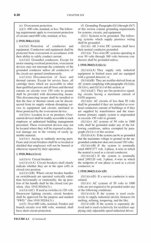
(e) Overcurrent protection.(e)(1) 600 volts, nominal, or less. The follow-
ing requirements apply to overcurrent protectionof circuits rated 600 volts, nominal, or less.
§ 1910.304(e)(1)(i)
(e)(1)(i) Protection of conductors andequipment. Conductors and equipment shall beprotected from overcurrent in accordance withtheir ability to safely conduct current.
(e)(1)(ii) Grounded conductors. Except formotor running overload protection, overcurrentdevices may not interrupt the continuity of thegrounded conductor unless all conductors ofthe circuit are opened simultaneously.
(e)(1)(iii) Disconnection of fuses andthermal cutouts. Except for service fuses, allcartridge fuses which are accessible to otherthan qualified persons and all fuses and thermalcutouts on circuits over 150 volts to groundshall be provided with disconnecting means.This disconnecting means shall be installed sothat the fuse or thermal cutout can be discon-nected from its supply without disrupting ser-vice to equipment and circuits unrelated tothose protected by the overcurrent device.
(e)(1)(iv) Location in or on premises. Over-current devices shall be readily accessible to eachemployee or authorized building managementpersonnel. These overcurrent devices may notbe located where they will be exposed to phys-ical damage nor in the vicinity of easily ig-nitable material.
(e)(1)(v) Arcing or suddenly moving parts.Fuses and circuit breakers shall be so located orshielded that employees will not be burned orotherwise injured by their operation.
§ 1910.304(e)(1)(vi)
(e)(1)(vi) Circuit breakers.(e)(1)(vi)(A) Circuit breakers shall clearly
indicate whether they are in the open (off) orclosed (on) position.
(e)(1)(vi)(B) Where circuit breaker handleson switchboards are operated vertically ratherthan horizontally or rotationally, the up posi-tion of the handle shall be the closed (on) po-sition. (See 1910.302(b)(3).)
(e)(1)(vi)(C) If used as switches in 120-volt,fluorescent lighting circuits, circuit breakersshall be approved for the purpose and marked“SWD.” (See 1910.302(b)(3).)
(e)(2) Over 600 volts, nominal. Feeders andbranch circuits over 600 volts, nominal, shallhave short-circuit protection.
(f) Grounding.Paragraphs(f)(1)through (f)(7)of this section contain grounding requirementsfor systems, circuits, and equipment.
(f)(1) Systems to be grounded. The follow-ing systems which supply premises wiringshall be grounded:
(f)(1)(i) All 3-wire DC systems shall havetheir neutral conductor grounded.
(f)(1)(ii) Two-wire DC systems operating atover 50 volts through 300 volts between con-ductors shall be grounded unless:
§ 1910.304(f)(1)(ii)(A)
(f)(1)(ii)(A) They supply only industrialequipment in limited areas and are equippedwith a ground detector; or
(f)(1)(ii)(B) They are rectifier-derived from anAC system complying with paragraphs (f)(1)(iii),(f)(1)(iv), and (f)(1)(v) of this section; or
(f)(1)(ii)(C) They are fire-protective signal-ing circuits having a maximum current of0.030 amperes.
(f)(1)(iii) AC circuits of less than 50 voltsshall be grounded if they are installed as over-head conductors outside of buildings or if theyare supplied by transformers and the trans-former primary supply system is ungroundedor exceeds 150 volts to ground.
(f)(1)(iv) AC systems of 50 volts to 1000volts shall be grounded under any of the fol-lowing conditions, unless exempted by para-graph (f)(1)(v) of this section:
(f)(1)(iv)(A) If the system can be so groundedthat the maximum voltage to ground on the un-grounded conductors does not exceed 150 volts;
(f)(1)(iv)(B) If the system is nominallyrated 480Y/277 volt, 3-phase, 4-wire in whichthe neutral is used as a circuit conductor;
(f)(1)(iv)(C) If the system is nominallyrated 240/120 volt, 3-phase, 4-wire in whichthe midpoint of one phase is used as a circuitconductor; or
§ 1910.304(f)(1)(iv)(D)
(f)(1)(iv)(D) If a service conductor is unin-sulated.
(f)(1)(v) AC systems of 50 volts to 1000volts are not required to be grounded under anyof the following conditions:
(f)(1)(v)(A) If the system is used exclu-sively to supply industrial electric furnaces formelting, refining, tempering, and the like.
(f)(1)(v)(B) If the system is separately de-rived and is used exclusively for rectifiers sup-plying only adjustable speed industrial drives.
6.30 CHAPTER SIX
FIGURE 6.1 (Continued)
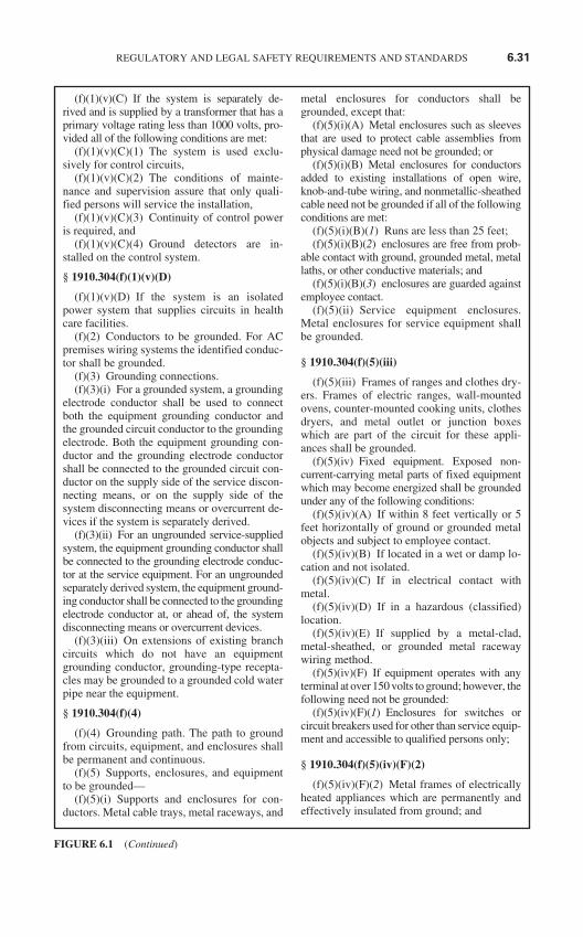
(f)(1)(v)(C) If the system is separately de-rived and is supplied by a transformer that has aprimary voltage rating less than 1000 volts, pro-vided all of the following conditions are met:
(f)(1)(v)(C)(1) The system is used exclu-sively for control circuits,
(f)(1)(v)(C)(2) The conditions of mainte-nance and supervision assure that only quali-fied persons will service the installation,
(f)(1)(v)(C)(3) Continuity of control poweris required, and
(f)(1)(v)(C)(4) Ground detectors are in-stalled on the control system.
§ 1910.304(f)(1)(v)(D)
(f)(1)(v)(D) If the system is an isolatedpower system that supplies circuits in healthcare facilities.
(f)(2) Conductors to be grounded. For ACpremises wiring systems the identified conduc-tor shall be grounded.
(f)(3) Grounding connections.(f)(3)(i) For a grounded system, a grounding
electrode conductor shall be used to connectboth the equipment grounding conductor andthe grounded circuit conductor to the groundingelectrode. Both the equipment grounding con-ductor and the grounding electrode conductorshall be connected to the grounded circuit con-ductor on the supply side of the service discon-necting means, or on the supply side of thesystem disconnecting means or overcurrent de-vices if the system is separately derived.
(f)(3)(ii) For an ungrounded service-suppliedsystem, the equipment grounding conductor shallbe connected to the grounding electrode conduc-tor at the service equipment. For an ungroundedseparately derived system, the equipment ground-ing conductor shall be connected to the groundingelectrode conductor at, or ahead of, the systemdisconnecting means or overcurrent devices.
(f)(3)(iii) On extensions of existing branchcircuits which do not have an equipmentgrounding conductor, grounding-type recepta-cles may be grounded to a grounded cold waterpipe near the equipment.
§ 1910.304(f)(4)
(f)(4) Grounding path. The path to groundfrom circuits, equipment, and enclosures shallbe permanent and continuous.
(f)(5) Supports, enclosures, and equipmentto be grounded—
(f)(5)(i) Supports and enclosures for con-ductors. Metal cable trays, metal raceways, and
metal enclosures for conductors shall begrounded, except that:
(f)(5)(i)(A) Metal enclosures such as sleevesthat are used to protect cable assemblies fromphysical damage need not be grounded; or
(f)(5)(i)(B) Metal enclosures for conductorsadded to existing installations of open wire,knob-and-tube wiring, and nonmetallic-sheathedcable need not be grounded if all of the followingconditions are met:
(f)(5)(i)(B)(1) Runs are less than 25 feet;(f)(5)(i)(B)(2) enclosures are free from prob-
able contact with ground, grounded metal, metallaths, or other conductive materials; and
(f)(5)(i)(B)(3) enclosures are guarded againstemployee contact.
(f)(5)(ii) Service equipment enclosures.Metal enclosures for service equipment shallbe grounded.
§ 1910.304(f)(5)(iii)
(f)(5)(iii) Frames of ranges and clothes dry-ers. Frames of electric ranges, wall-mountedovens, counter-mounted cooking units, clothesdryers, and metal outlet or junction boxeswhich are part of the circuit for these appli-ances shall be grounded.
(f)(5)(iv) Fixed equipment. Exposed non-current-carrying metal parts of fixed equipmentwhich may become energized shall be groundedunder any of the following conditions:
(f)(5)(iv)(A) If within 8 feet vertically or 5feet horizontally of ground or grounded metalobjects and subject to employee contact.
(f)(5)(iv)(B) If located in a wet or damp lo-cation and not isolated.
(f)(5)(iv)(C) If in electrical contact withmetal.
(f)(5)(iv)(D) If in a hazardous (classified)location.
(f)(5)(iv)(E) If supplied by a metal-clad,metal-sheathed, or grounded metal racewaywiring method.
(f)(5)(iv)(F) If equipment operates with anyterminal at over 150 volts to ground; however, thefollowing need not be grounded:
(f)(5)(iv)(F)(1) Enclosures for switches orcircuit breakers used for other than service equip-ment and accessible to qualified persons only;
§ 1910.304(f)(5)(iv)(F)(2)
(f)(5)(iv)(F)(2) Metal frames of electricallyheated appliances which are permanently andeffectively insulated from ground; and
REGULATORY AND LEGAL SAFETY REQUIREMENTS AND STANDARDS 6.31
FIGURE 6.1 (Continued)
(f)(5)(iv)(F)(3) The cases of distribution ap-paratus such as transformers and capacitorsmounted on wooden poles at a height exceed-ing 8 feet above ground or grade level.
(f)(5)(v) Equipment connected by cord andplug. Under any of the conditions described inparagraphs (f)(5)(v)(A) through (f)(5)(v)(C) ofthis section, exposed non-current-carryingmetal parts of cord- and plug-connected equip-ment which may become energized shall begrounded.
(f)(5)(v)(A) If in hazardous (classified) lo-cations (see 1910.307).
(f)(5)(v)(B) If operated at over 150 volts toground, except for guarded motors and metalframes of electrically heated appliances if theappliance frames are permanently and effec-tively insulated from ground.
(f)(5)(v)(C) If the equipment is of the fol-lowing types:
(f)(5)(v)(C)(1) Refrigerators, freezers, andair conditioners;
(f)(5)(v)(C)(2) Clothes-washing, clothes-drying and dishwashing machines, sumppumps, and electrical aquarium equipment;
(f)(5)(v)(C)(3) Hand-held motor-operatedtools;
§ 1910.304(f)(5)(v)(C)(4)
(f)(5)(v)(C)(4) Motor-operated appliancesof the following types: hedge clippers, lawnmowers, snow blowers, and wet scrubbers;
(f)(5)(v)(C)(5) Cord- and plug-connectedappliances used in damp or wet locations or byemployees standing on the ground or on metalfloors or working inside of metal tanks or boilers;
(f)(5)(v)(C)(6) Portable and mobile X-rayand associated equipment;
(f)(5)(v)(C)(7) Tools likely to be used inwet and conductive locations; and
(f)(5)(v)(C)(8) Portable hand lamps.Tools likely to be used in wet and conduc-
tive locations need not be grounded if suppliedthrough an isolating transformer with an un-grounded secondary of not over 50 volts.Listed or labeled portable tools and appliancesprotected by an approved system of double in-sulation, or its equivalent, need not begrounded. If such a system is employed, theequipment shall be distinctively marked to in-dicate that the tool or appliance utilizes an ap-proved system of double insulation.
(f)(5)(vi) Nonelectrical equipment. Themetal parts of the following nonelectrical
equipment shall be grounded: frames andtracks of electrically operated cranes; frames ofnonelectrically driven elevator cars to whichelectric conductors are attached; hand operatedmetal shifting ropes or cables of electric eleva-tors, and metal partitions, grill work, and simi-lar metal enclosures around equipment of over750 volts between conductors.
§ 1910.304(f)(6)
(f)(6) Methods of grounding fixed equip-ment.
(f)(6)(i) Non-current-carrying metal parts offixed equipment, if required to be grounded bythis subpart, shall be grounded by an equipmentgrounding conductor which is contained withinthe same raceway, cable, or cord, or runs with orencloses the circuit conductors. For DC circuitsonly, the equipment grounding conductor maybe run separately from the circuit conductors.
(f)(6)(ii) Electric equipment is consideredto be effectively grounded if it is secured to,and in electrical contact with, a metal rack orstructure that is provided for its support and themetal rack or structure is grounded by themethod specified for the non-current-carryingmetal parts of fixed equipment in paragraph(f)(6)(i) of this section. For installations madebefore April 16, 1981, only, electric equipmentis also considered to be effectively grounded ifit is secured to, and in metallic contact with, thegrounded structural metal frame of a building.Metal car frames supported by metal hoistingcables attached to or running over metalsheaves or drums of grounded elevator ma-chines are also considered to be effectivelygrounded.
(f)(7) Grounding of systems and circuits of1000 volts and over (high voltage.)—
(f)(7)(i) General. If high voltage systemsare grounded, they shall comply with all ap-plicable provisions of paragraphs (f)(1)through (f)(6) of this section as supplementedand modified by this paragraph (f)(7).
(f)(7)(ii) Grounding of systems supplyingportable or mobile equipment. (See1910.302(b)(3).) Systems supplying portableor mobile high voltage equipment, other thansubstations installed on a temporary basis, shallcomply with the following:
§ 1910.304(f)(7)(ii)(A)
(f)(7)(ii)(A) Portable and mobile high volt-age equipment shall be supplied from a system
6.32 CHAPTER SIX
FIGURE 6.1 (Continued)
having its neutral grounded through an imped-ance. If a delta-connected high voltage systemis used to supply the equipment, a system neu-tral shall be derived.
(f)(7)(ii)(B) Exposed non-current-carryingmetal parts of portable and mobile equipmentshall be connected by an equipment groundingconductor to the point at which the system neu-tral impedance is grounded.
(f)(7)(ii)(C) Ground-fault detection andrelaying shall be provided to automaticallydeenergize any high voltage system compo-nent which has developed a ground fault.The continuity of the equipment groundingconductor shall be continuously monitoredso as to deenergize automatically the highvoltage feeder to the portable equipmentupon loss of continuity of the equipmentgrounding conductor.
(f)(7)(ii)(D) The grounding electrode towhich the portable or mobile equipment sys-tem neutral impedance is connected shall beisolated from and separated in the ground by atleast 20 feet from any other system or equip-ment grounding electrode, and there shall be nodirect connection between the grounding elec-trodes, such as buried pipe, fence, etc.
(f)(7)(iii) Grounding of equipment. All non-current-carrying metal parts of portable equip-ment and fixed equipment including theirassociated fences, housings, enclosures, and sup-porting structures shall be grounded. However,equipment which is guarded by location and iso-lated from ground need not be grounded. Addi-tionally, pole-mounted distribution apparatus at aheight exceeding 8 feet above ground or gradelevel need not be grounded.
[46 FR 4056, Jan. 16, 1981; 46 FR 40185, Aug. 7,1981, as amended at 55 FR 32015, Aug. 6, 1990]
§ 1910.305 Wiring methods, components,and equipment for general use.
(a) Wiring methods. The provisions of thissection do not apply to the conductors that are anintegral part of factory-assembled equipment.
(a)(1) General requirements—(a)(1)(i) Electrical continuity of metal race-
ways and enclosures. Metal raceways, cablearmor, and other metal enclosures for conduc-tors shall be metallically joined together into acontinuous electric conductor and shall be soconnected to all boxes, fittings, and cabinets asto provide effective electrical continuity.
(a)(1)(ii) Wiring in ducts. No wiring sys-tems of any type shall be installed in ducts usedto transport dust, loose stock or flammable va-pors. No wiring system of any type may be in-stalled in any duct used for vapor removal orfor ventilation of commercial-type cookingequipment, or in any shaft containing only suchducts.
(a)(2) Temporary wiring. Temporaryelectrical power and lighting wiring methodsmay be of a class less than would be requiredfor a permanent installation. Except asspecifically modified in this paragraph, allother requirements of this subpart for perma-nent wiring shall apply to temporary wiringinstallations.
§ 1910.305(a)(2)(i)
(a)(2)(i) Uses permitted, 600 volts, nomi-nal, or less. Temporary electrical power andlighting installations 600 volts, nominal, or lessmay be used only:
(a)(2)(i)(A) During and for remodeling,maintenance, repair, or demolition of build-ings, structures, or equipment, and similar ac-tivities;
(a)(2)(i)(B) For experimental or develop-ment work, and
(a)(2)(i)(C) For a period not to exceed 90days for Christmas decorative lighting, carni-vals, and similar purposes.
(a)(2)(ii) Uses permitted, over 600 volts,nominal. Temporary wiring over 600 volts,nominal, may be used only during periods oftests, experiments, or emergencies.
(a)(2)(iii) General requirements for tempo-rary wiring.
(a)(2)(iii)(A) Feeders shall originate in anapproved distribution center. The conductorsshall be run as multiconductor cord or cable as-semblies, or, where not subject to physicaldamage, they may be run as open conductorson insulators not more than 10 feet apart.
§ 1910.305(a)(2)(iii)(B)
(a)(2)(iii)(B) Branch circuits shall originatein an approved power outlet or panelboard. Con-ductors shall be multiconductor cord or cable as-semblies or open conductors. If run as openconductors they shall be fastened at ceilingheight every 10 feet. No branch-circuit conduc-tor may be laid on the floor. Each branch circuitthat supplies receptacles or fixed equipment
REGULATORY AND LEGAL SAFETY REQUIREMENTS AND STANDARDS 6.33
FIGURE 6.1 (Continued)
shall contain a separate equipment groundingconductor if run as open conductors.
(a)(2)(iii)(C) Receptacles shall be of thegrounding type. Unless installed in a completemetallic raceway, each branch circuit shallcontain a separate equipment grounding con-ductor and all receptacles shall be electricallyconnected to the grounding conductor.
(a)(2)(iii)(D) No bare conductors nor earthreturns may be used for the wiring of any tem-porary circuit.
(a)(2)(iii)(E) Suitable disconnecting switchesor plug connectors shall be installed to permit thedisconnection of all ungrounded conductors ofeach temporary circuit.
(a)(2)(iii)(F) Lamps for general illumina-tion shall be protected from accidental contactor breakage. Protection shall be provided by el-evation of at least 7 feet from normal workingsurface or by a suitable fixture or lampholderwith a guard.
(a)(2)(iii)(G) Flexible cords and cables shallbe protected from accidental damage. Sharpcorners and projections shall be avoided.Where passing through doorways or otherpinch points, flexible cords and cables shall beprovided with protection to avoid damage.
§ 1910.305(a)(3)
(a)(3) Cable trays.(a)(3)(i) Uses permitted.(a)(3)(i)(A) Only the following may be in-
stalled in cable tray systems:(a)(3)(i)(A)(1) Mineral-insulated metal-
sheathed cable (Type MI);(a)(3)(i)(A)(2) Armored cable (Type AC);(a)(3)(i)(A)(3) Metal-clad cable (Type MC);(a)(3)(i)(A)(4) Power-limited tray cable
(Type PLTC);(a)(3)(i)(A)(5) Nonmetallic-sheathed cable
(Type NM or NMC);(a)(3)(i)(A)(6) Shielded nonmetallic-
sheathed cable (Type SNM);(a)(3)(i)(A)(7) Multiconductor service-
entrance cable (Type SE or USE);(a)(3)(i)(A)(8) Multiconductor underground
feeder and branch-circuit cable (Type UF);(a)(3)(i)(A)(9) Power and control tray cable
(Type TC);(a)(3)(i)(A)(10) Other factory-assembled,
multiconductor control, signal, or powerca-bles which are specifically approved for in-stallation in cable trays; or
§ 1910.305(a)(3)(i)(A)(11)
(a)(3)(i)(A)(11) Any approved conduit orraceway with its contained conductors.
(a)(3)(i)(B) In industrial establishments only,where conditions of maintenance and supervi-sion assure that only qualified persons will ser-vice the installed cable tray system, the followingcables may also be installed in ladder, ventilatedtrough, or 4 inch ventilated channel-type cabletrays:
(a)(3)(i)(B)(1) Single conductor cableswhich are 250 MCM or larger and are TypesRHH, RHW, MV, USE, or THW, and other250 MCM or larger single conductor cables ifspecifically approved for installation in cabletrays. Where exposed to direct rays of the sun,cables shall be sunlight-resistant.
(a)(3)(i)(B)(2) Type MV cables, where ex-posed to direct rays of the sun, shall be sun-light-resistant.
(a)(3)(i)(C) Cable trays in hazardous (clas-sified) locations shall contain only the cabletypes permitted in such locations.
(a)(3)(ii) Uses not permitted. Cable traysystems may not be used in hoistways or wheresubjected to severe physical damage.
(a)(4) Open wiring on insulators—(a)(4)(i) Uses permitted. Open wiring on in-
sulators is only permitted on systems of 600volts, nominal, or less for industrial or agricul-tural establishments and for services.
§ 1910.305(a)(4)(ii)
(a)(4)(ii) Conductor supports. Conductorsshall be rigidly supported on noncombustible,nonabsorbent insulating materials and may notcontact any other objects.
(a)(4)(iii) Flexible nonmetallic tubing. Indry locations where not exposed to severephysical damage, conductors may be sepa-rately enclosed in flexible nonmetallic tubing.The tubing shall be in continuous lengths notexceeding 15 feet and secured to the surface bystraps at intervals not exceeding 4 feet 6 inches.
(a)(4)(iv) Through walls, floors, wood crossmembers, etc. Open conductors shall be sepa-rated from contact with walls, floors, woodcross members, or partitions through whichthey pass by tubes or bushings of noncom-bustible, nonabsorbent insulating material. Ifthe bushing is shorter than the hole, a water-proof sleeve of nonconductive material shall beinserted in the hole and an insulating bushingslipped into the sleeve at each end in such a
6.34 CHAPTER SIX
FIGURE 6.1 (Continued)
manner as to keep the conductors absolutely outof contact with the sleeve. Each conductor shallbe carried through a separate tube or sleeve.
(a)(4)(v) Protection from physical damage.Conductors within 7 feet from the floor areconsidered exposed to physical damage. Whereopen conductors cross ceiling joints and wallstuds and are exposed to physical damage, theyshall be protected.
§ 1910.305(b)
(b) Cabinets, boxes, and fittings—(b)(1) Conductors entering boxes, cabinets,
or fittings. Conductors entering boxes, cabi-nets, or fittings shall also be protected from abra-sion, and openings through which conductorsenter shall be effectively closed. Unused open-ings in cabinets, boxes, and fittings shall be ef-fectively closed.
(b)(2) Covers and canopies. All pull boxes,junction boxes, and fittings shall be providedwith covers approved for the purpose. If metalcovers are used they shall be grounded. In com-pleted installations each outlet box shall have acover, faceplate, or fixture canopy. Covers ofoutlet boxes having holes through which flexi-ble cord pendants pass shall be provided withbushings designed for the purpose or shall havesmooth, well-rounded surfaces on which thecords may bear.
(b)(3) Pull and junction boxes for systemsover 600 volts, nominal. In addition to other re-quirements in this section for pull and junctionboxes, the following shall apply to these boxesfor systems over 600 volts, nominal:
(b)(3)(i) Boxes shall provide a complete en-closure for the contained conductors or cables.
(b)(3)(ii) Boxes shall be closed by suitablecovers securely fastened in place. Under-ground box covers that weigh over 100 poundsmeet this requirement. Covers for boxes shallbe permanently marked “HIGH VOLTAGE.”The marking shall be on the outside of the boxcover and shall be readily visible and legible.
§ 1910.305(c)
(c) Switches—(c)(1) Knife switches. Single-throw knife
switches shall be so connected that the bladesare dead when the switch is in the open posi-tion. Single-throw knife switches shall be soplaced that gravity will not tend to close them.Single-throw knife switches approved for usein the inverted position shall be provided with
a locking device that will ensure that theblades remain in the open position when soset. Double-throw knife switches may bemounted so that the throw will be either verti-cal or horizontal. However, if the throw is ver-tical a locking device shall be provided toensure that the blades remain in the open posi-tion when so set.
(c)(2) Faceplates for flush-mounted snapswitches. Flush snap switches that are mountedin ungrounded metal boxes and located withinreach of conducting floors or other conductingsurfaces shall be provided with faceplates ofnonconducting, noncombustible material.
(d) Switchboards and panelboards.Switchboards that have any exposed live partsshall be located in permanently dry locationsand accessible only to qualified persons. Panel-boards shall be mounted in cabinets, cutoutboxes, or enclosures approved for the purposeand shall be dead front. However, panelboardsother than the dead front externally-operabletype are permitted where accessible only toqualified persons. Exposed blades of knifeswitches shall be dead when open.
(e) Enclosures for damp or wet locations.(e)(1) Cabinets, cutout boxes, fittings,
boxes, and panelboard enclosures in damp orwet locations shall be installed so as to preventmoisture or water from entering and accumu-lating within the enclosures. In wet locationsthe enclosures shall be weatherproof.
(e)(2) Switches, circuit breakers, andswitchboards installed in wet locations shall beenclosed in weatherproof enclosures.
§ 1910.305(f)
(f) Conductors for general wiring. All con-ductors used for general wiring shall be insu-lated unless otherwise permitted in thisSubpart. The conductor insulation shall be of atype that is approved for the voltage, operatingtemperature, and location of use. Insulated con-ductors shall be distinguishable by appropriatecolor or other suitable means as being groundedconductors, ungrounded conductors, or equip-ment grounding conductors.
(g) Flexible cords and cables—(g)(1) Use of flexible cords and cables.(g)(1)(i) Flexible cords and cables shall be
approved and suitable for conditions of use andlocation. Flexible cords and cables shall beused only for:
(g)(1)(i)(A) Pendants;(g)(1)(i)(B) Wiring of fixtures;
REGULATORY AND LEGAL SAFETY REQUIREMENTS AND STANDARDS 6.35
FIGURE 6.1 (Continued)
(g)(1)(i)(C) Connection of portable lampsor appliances;
(g)(1)(i)(D) Elevator cables;(g)(1)(i)(E) Wiring of cranes and hoists;(g)(1)(i)(F) Connection of stationary equip-
ment to facilitate their frequent interchange;(g)(1)(i)(G) Prevention of the transmission
of noise or vibration;(g)(1)(i)(H) Appliances where the fastening
means and mechanical connections are de-signed to permit removal for maintenance andrepair; or
§ 1910.305(g)(1)(i)(i)
(g)(1)(i)(I) Data processing cables ap-proved as a part of the data processing system.
(g)(1)(ii) If used as permitted in paragraphs(g)(1)(i)(C), (g)(1)(i)(F), or (g)(1)(i)(H) ofthis section, the flexible cord shall be equippedwith an attachment plug and shall be energizedfrom an approved receptacle outlet.
(g)(1)(iii) Unless specifically permitted inparagraph (g)(1)(i) of this section, flexiblecords and cables may not be used:
(g)(1)(iii)(A) As a substitute for the fixedwiring of a structure;
(g)(1)(iii)(B) Where run through holes inwalls, ceilings, or floors;
(g)(1)(iii)(C) Where run through doorways,windows, or similar openings;
(g)(1)(iii)(D) Where attached to buildingsurfaces; or
(g)(1)(iii)(E) Where concealed behind build-ing walls, ceilings, or floors.
(g)(1)(iv) Flexible cords used in show win-dows and showcases shall be Type S, SO, SJ,SJO, ST, STO, SJT, SJTO, or AFS except forthe wiring of chain-supported lighting fixturesand supply cords for portable lamps and othermerchandise being displayed or exhibited.
§ 1910.305(g)(2)
(g)(2) Identification, splices, and termina-tions.
(g)(2)(i) A conductor of a flexible cord orcable that is used as a grounded conductor or anequipment grounding conductor shall be distin-guishable from other conductors. Types SJ,SJO, SJT, SJTO, S, SO, ST, and STO shall bedurably marked on the surface with the typedesignation, size, and number of conductors.
(g)(2)(ii) Flexible cords shall be used only incontinuous lengths without splice or tap. Hardservice flexible cords No. 12 or larger may berepaired if spliced so that the splice retains the
insulation, outer sheath properties, and usagecharacteristics of the cord being spliced.
(g)(2)(iii) Flexible cords shall be connectedto devices and fittings so that strain relief is pro-vided which will prevent pull from being di-rectly transmitted to joints or terminal screws.
(h) Portable cables over 600 volts, nominal.Multiconductor portable cable for use in supply-ing power to portable or mobile equipment atover 600 volts, nominal, shall consist of No. 8 orlarger conductors employing flexible stranding.Cables operated at over 2,000 volts shall beshielded for the purpose of confining the volt-age stresses to the insulation. Grounding con-ductors shall be provided. Connectors for thesecables shall be of a locking type with provisionsto prevent their opening or closing while ener-gized. Strain relief shall be provided at connec-tions and terminations. Portable cables may notbe operated with splices unless the splices are ofthe permanent molded, vulcanized, or other ap-proved type. Termination enclosures shall besuitably marked with a high voltage hazardwarning, and terminations shall be accessibleonly to authorized and qualified personnel.
§ 1910.305(i)
(i) Fixture wires—(i)(1) General. Fixture wires shall be ap-
proved for the voltage, temperature, and loca-tion of use. A fixture wire which is used as agrounded conductor shall be identified.
(i)(2) Uses permitted. Fixture wires may beused:
(i)(2)(i) For installation in lighting fixturesand in similar equipment where enclosed orprotected and not subject to bending or twistingin use; or
(i)(2)(ii) For connecting lighting fixtures tothe branch-circuit conductors supplying thefixtures.
(i)(3) Uses not permitted. Fixture wires maynot be used as branch-circuit conductors exceptas permitted for Class 1 power limited circuits.
(j) Equipment for general use—(j)(1) Lighting fixtures, lampholders, lamps,
and receptacles.(j)(1)(i) Fixtures, lampholders, lamps,
rosettes, and receptacles may have no live partsnormally exposed to employee contact. How-ever, rosettes and cleat-type lampholders and re-ceptacles located at least 8 feet above the floormay have exposed parts.
(j)(1)(ii) Handlamps of the portable typesupplied through flexible cords shall be
6.36 CHAPTER SIX
FIGURE 6.1 (Continued)
equipped with a handle of molded compositionor other material approved for the purpose, anda substantial guard shall be attached to the lam-pholder or the handle.
§ 1910.305(j)(1)(iii)
(j)(1)(iii) Lampholders of the screw-shelltype shall be installed for use as lampholdersonly. Lampholders installed in wet or damp lo-cations shall be of the weatherproof type.
(j)(1)(iv) Fixtures installed in wet or damplocations shall be approved for the purpose andshall be so constructed or installed that watercannot enter or accumulate in wireways, lam-pholders, or other electrical parts.
(j)(2) Receptacles, cord connectors, and at-tachment plugs (caps).
(j)(2)(i) Receptacles, cord connectors, andattachment plugs shall be constructed so that noreceptacle or cord connector will accept an at-tachment plug with a different voltage or cur-rent rating than that for which the device isintended. However, a 20-ampere T-slot recepta-cle or cord connector may accept a 15-ampereattachment plug of the same voltage rating.
(j)(2)(ii) A receptacle installed in a wet ordamp location shall be suitable for the location.
(j)(3) Appliances.(j)(3)(i) Appliances, other than those in
which the current-carrying parts at high temper-atures are necessarily exposed, may have no liveparts normally exposed to employee contact.
(j)(3)(ii) A means shall be provided to dis-connect each appliance.
§ 1910.305(j)(3)(iii)
(j)(3)(iii) Each appliance shall be markedwith its rating in volts and amperes or volts andwatts.
(j)(4) Motors. This paragraph applies to mo-tors, motor circuits, and controllers.
(j)(4)(i) In sight from. If specified that onepiece of equipment shall be “in sight from” an-other piece of equipment, one shall be visibleand not more than 50 feet from the other.
(j)(4)(ii) Disconnecting means.(j)(4)(ii)(A) A disconnecting means shall be
located in sight from the controller location.However, a single disconnecting means may belocated adjacent to a group of coordinated con-trollers mounted adjacent to each other on amulti-motor continuous process machine. Thecontroller disconnecting means for motorbranch circuits over 600 volts, nominal, may beout of sight of the controller, if the controller is
marked with a warning label giving the locationand identification of the disconnecting meanswhich is to be locked in the open position.
(j)(4)(ii)(B) The disconnecting means shalldisconnect the motor and the controller fromall ungrounded supply conductors and shall beso designed that no pole can be operated inde-pendently.
§ 1910.305(j)(4)(ii)(C)
(j)(4)(ii)(C) If a motor and the driven ma-chinery are not in sight from the controller lo-cation, the installation shall comply with one ofthe following conditions:
(j)(4)(ii)(C)(1) The controller disconnectingmeans shall be capable of being locked in theopen position.
(j)(4)(ii)(C)(2) A manually operable switchthat will disconnect the motor from its sourceof supply shall be placed in sight from themotor location.
(j)(4)(ii)(D) The disconnecting means shallplainly indicate whether it is in the open (off)or closed (on) position.
(j)(4)(ii)(E) The disconnecting means shallbe readily accessible. If more than one discon-nect is provided for the same equipment, onlyone need be readily accessible.
(j)(4)(ii)(F) An individual disconnectingmeans shall be provided for each motor, but asingle disconnecting means may be used for agroup of motors under any one of the followingconditions:
(j)(4)(ii)(F)(1) If a number of motors drivespecial parts of a single machine or piece of ap-paratus, such as a metal or woodworking ma-chine, crane, or hoist;
(j)(4)(ii)(F)(2) If a group of motors is underthe protection of one set of branch-circuit pro-tective devices; or
§ 1910.305(j)(4)(ii)(F)(3)
(j)(4)(ii)(F)(3) If a group of motors is in asingle room in sight from the location of thedisconnecting means.
(j)(4)(iii) Motor overload, short-circuit, andground-fault protection. Motors, motor-controlapparatus, and motor branch-circuit conductorsshall be protected against overheating due tomotor overloads or failure to start, and againstshort-circuits or ground faults. These provisionsshall not require overload protection that willstop a motor where a shutdown is likely to intro-duce additional or increased hazards, as in thecase of fire pumps, or where continued operation
REGULATORY AND LEGAL SAFETY REQUIREMENTS AND STANDARDS 6.37
FIGURE 6.1 (Continued)
of a motor is necessary for a safe shutdown ofequipment or process and motor overload sens-ing devices are connected to a supervised alarm.
(j)(4)(iv) Protection of live parts—all volt-ages.
(j)(4)(iv)(A) Stationary motors having com-mutators, collectors, and brush rigging locatedinside of motor end brackets and not conduc-tively connected to supply circuits operating atmore than 150 volts to ground need not havesuch parts guarded. Exposed live parts of mo-tors and controllers operating at 50 volts ormore between terminals shall be guarded againstaccidental contact by any of the following:
(j)(4)(iv)(A)(1) By installation in a room orenclosure that is accessible only to qualifiedpersons;
§ 1910.305(j)(4)(iv)(A)(2)
(j)(4)(iv)(A)(2) By installation on a suitablebalcony, gallery, or platform, so elevated andarranged as to exclude unqualified persons; or
(j)(4)(iv)(A)(3) By elevation 8 feet or moreabove the floor.
(j)(4)(iv)(B) Where live parts of motors orcontrollers operating at over 150 volts toground are guarded against accidental contactonly by location, and where adjustment orother attendance may be necessary during theoperation of the apparatus, suitable insulatingmats or platforms shall be provided so that theattendant cannot readily touch live parts unlessstanding on the mats or platforms.
(j)(5) Transformers.(j)(5)(i) The following paragraphs cover the
installation of all transformers except the fol-lowing:
(j)(5)(i)(A) Current transformers;(j)(5)(i)(B) Dry-type transformers installed
as a component part of other apparatus;(j)(5)(i)(C) Transformers which are an inte-
gral part of an X-ray, high frequency, or elec-trostatic-coating apparatus;
§ 1910.305(j)(5)(i)(D)
(j)(5)(i)(D) Transformers used withClass 2 and Class 3 circuits, sign and outlinelighting, electric discharge lighting, and power-limited fire-protective signaling circuits; and
(j)(5)(i)(E) Liquid-filled or dry-typetransformers used for research, development,or testing, where effective safeguard arrange-ments are provided.
(j)(5)(ii) The operating voltage of exposedlive parts of transformer installations shall be
indicated by warning signs or visible markingson the equipment or structure.
(j)(5)(iii) Dry-type, high fire point liq-uid-insulated, and askarel-insulated trans-formers installed indoors and rated over 35kVshall be in a vault.
(j)(5)(iv) If they present a fire hazard to em-ployees, oil-insulated transformers installed in-doors shall be in a vault.
(j)(5)(v) Combustible material, combustiblebuildings and parts of buildings, fire escapes,and door and window openings shall be safe-guarded from fires which may originate in oil-insulated transformers attached to or adjacent toa building or combustible material.
(j)(5)(vi) Transformer vaults shall be con-structed so as to contain fire and combustible liq-uids within the vault and to prevent unauthorizedaccess. Locks and latches shall be so arrangedthat a vault door can be readily opened from theinside.
§ 1910.305(j)(5)(vii)
(j)(5)(vii) Any pipe or duct system foreignto the vault installation may not enter or passthrough a transformer vault.
(j)(5)(viii) Materials may not be stored intransformer vaults.
(j)(6) Capacitors.(j)(6)(i) All capacitors, except surge capaci-
tors or capacitors included as a component partof other apparatus, shall be provided with an au-tomatic means of draining the stored charge afterthe capacitor is disconnected from its source ofsupply.
(j)(6)(ii) Capacitors rated over 600 volts,nominal, shall comply with the following addi-tional requirements:
(j)(6)(ii)(A) Isolating or disconnectingswitches (with no interrupting rating) shall be in-terlocked with the load interrupting device orshall be provided with prominently displayedcaution signs to prevent switching load current.
(j)(6)(ii)(B) For series capacitors (see1910.302(b)(3)), the proper switching shall beassured by use of at least one of the following:
(j)(6)(ii)(B)(1) Mechanically sequencedisolating and bypass switches,
(j)(6)(ii)(B)(2) Interlocks, or
§ 1910.305(j)(6)(ii)(B)(3)
(j)(6)(ii)(B)(3) Switching procedureprominentlydisplayedat the switching location.
(j)(7) Storage batteries. Provisions shall bemade for sufficient diffusion and ventilation of
6.38 CHAPTER SIX
FIGURE 6.1 (Continued)
gases from storage batteries to prevent the ac-cumulation of explosive mixtures.
[46 FR 4056, Jan. 16, 1981; 46 FR 40185, Aug. 7,1981]
§ 1910.306 Specific purpose equipment andinstallations.
(a) Electric signs and outline lighting—(a)(1) Disconnecting means. Signs operated
by electronic or electromechanical controllerslocated outside the sign shall have a disconnect-ing means located inside the controller enclo-sure or within sight of the controller location,and it shall be capable of being locked in theopen position. Such disconnecting means shallhave no pole that can be operated independently,and it shall open all ungrounded conductors thatsupply the controller and sign. All other signs,except the portable type, and all outline lightinginstallations shall have an externally operabledisconnecting means which can open all un-grounded conductors and is within the sight ofthe sign or outline lighting it controls.
(a)(2) Doors or covers giving access to unin-sulated parts of indoor signs or outline lightingexceeding 600 volts and accessible to other thanqualified persons shall either be provided with in-terlock switches to disconnect the primary circuitor shall be so fastened that the use of other thanordinary tools will be necessary to open them.
§ 1910.306(b)
(b) Cranes and hoists. This paragraph ap-plies to the installation of electric equipmentand wiring used in connection with cranes,monorail hoists, hoists, and all runways.
(b)(1) Disconnecting means. A readily ac-cessible disconnecting means—
(b)(1)(i) shall be provided between the run-way contact conductors and the power supply.
(b)(1)(ii) Another disconnecting means, ca-pable of being locked in the open position,shall be provided in the leads from the runwaycontact conductors or other power supply onany crane or monorail hoist.
(b)(1)(ii)(A) If this additional disconnectingmeans is not readily accessible from the craneor monorail hoist operating station, means shallbe provided at the operating station to open thepower circuit to all motors of the crane ormonorail hoist.
(b)(1)(ii)(B) The additional disconnect maybe omitted if a monorail hoist or hand-
propelled crane bridge installation meets all ofthe following:
(b)(1)(ii)(B)(1) The unit is floor controlled;(b)(1)(ii)(B)(2) The unit is within view of
the power supply disconnecting means; and(b)(1)(ii)(B)(3) No fixed work platform has
been provided for servicing the unit.
§ 1910.306(b)(2)
(b)(2) Control. A limit switch or other de-vice shall be provided to prevent the load blockfrom passing the safe upper limit of travel ofany hoisting mechanism.
(b)(3) Clearance. The dimension of the work-ing space in the direction of access to live partswhich may require examination, adjustment, ser-vicing, or maintenance while alive shall be aminimum of 2 feet 6 inches. Where controls areenclosed in cabinets, the door(s) shall either openat least 90 degrees or be removable.
(c) Elevators, dumbwaiters, escalators, andmoving walks—
(c)(1) Disconnecting means. Elevators, dumb-waiters, escalators, and moving walks shall havea single means for disconnecting all ungroundedmain power supply conductors for each unit.
(c)(2) Warning signs. If interconnectionsbetween control panels are necessary for oper-ation of the system on a multicar installationthat remains energized from a source other thanthe disconnecting means, a warning sign shallbe mounted on or adjacent to the disconnectingmeans. The sign shall be clearly legible andshall read “Warning—Parts of the controlpanel are not de-energized by this switch.”(See 1910.302(b)(3).)
(c)(3) Control panels. If control panels arenot located in the same space as the drive ma-chine, they shall be located in cabinets withdoors or panels capable of being lockedclosed.
§ 1910.306(d)
(d) Electric welders—disconnecting means.(d)(1) A disconnecting means shall be pro-
vided in the supply circuit for each motor-generator arc welder, and for each ACtransformer and DC rectifier arc welder whichis not equipped with a disconnect mounted asan integral part of the welder.
(d)(2) A switch or circuit breaker shall beprovided by which each resistance welder andits control equipment can be isolated fromthe supply circuit. The ampere rating of this
REGULATORY AND LEGAL SAFETY REQUIREMENTS AND STANDARDS 6.39
FIGURE 6.1 (Continued)
disconnecting means may not be less than thesupply conductor ampacity.
(e) Data processing systems—disconnect-ing means. A disconnecting means shall beprovided to disconnect the power to all elec-tronic equipment in data processing or com-puter rooms. This disconnecting means shall becontrolled from locations readily accessible tothe operator at the principal exit doors. Thereshall also be a similar disconnecting means todisconnect the air conditioning system servingthis area.
(f) X-Ray equipment. This paragraph ap-plies to X-ray equipment for other than medicalor dental use.
(f)(1) Disconnecting means.(f)(1)(i) A disconnecting means shall be
provided in the supply circuit. The disconnect-ing means shall be operable from a locationreadily accessible from the X-ray control. Forequipment connected to a 120-volt branch cir-cuit of 30 amperes or less, a grounding-type at-tachment plug cap and receptacle of properrating may serve as a disconnecting means.
§ 1910.306(f)(1)(ii)
(f)(1)(ii) If more than one piece of equip-ment is operated from the same high-voltagecircuit, each piece or each group of equipmentas a unit shall be provided with a high-voltageswitch or equivalent disconnecting means. Thisdisconnecting means shall be constructed, en-closed, or located so as to avoid contact by em-ployees with its live parts.
(f)(2) Control—(f)(2)(i) Radiographic and fluoroscopic
types. Radiographic and fluoroscopic-typeequipment shall be effectively enclosed or shallhave interlocks that de-energize the equipmentautomatically to prevent ready access to livecurrent-carrying parts.
(f)(2)(ii) Diffraction and irradiation types.Diffraction- and irradiation-type equipmentshall be provided with a means to indicatewhen it is energized unless the equipment orinstallation is effectively enclosed or is pro-vided with interlocks to prevent access to livecurrent-carrying parts during operation.
(g) Induction and dielectric heating equip-ment—
(g)(1) Scope. Paragraphs (g)(2) and (g)(3) ofthis section cover induction and dielectric heat-ing equipment and accessories for industrial andscientific applications, but not for medical ordental applications or for appliances.
(g)(2) Guarding and grounding.(g)(2)(i) Enclosures. The converting appa-
ratus (including the DC line) and high-frequencyelectric circuits (excluding the output circuitsand remote-control circuits) shall be com-pletely contained within enclosures of non-combustible material.
§ 1910.306(g)(2)(ii)
(g)(2)(ii) Panel controls. All panel controlsshall be of dead-front construction.
(g)(2)(iii) Access to internal equipment.Where doors are used for access to voltagesfrom 500 to 1000 volts AC or DC, either doorlocks or interlocks shall be provided. Wheredoors are used for access to voltages of over1000 volts AC or DC, either mechanical lock-outs with a disconnecting means to prevent ac-cess until voltage is removed from the cubicle,or both door interlocking and mechanical doorlocks, shall be provided.
(g)(2)(iv) Warning labels. “Danger” labelsshall be attached on the equipment and shall beplainly visible even when doors are open orpanels are removed from compartments con-taining voltages of over 250 volts AC or DC.
(g)(2)(v) Work applicator shielding.Protective cages or adequate shielding shallbe used to guard work applicators other thaninduction heating coils. Induction heatingcoils shall be protected by insulation and/orrefractory materials. Interlock switches shallbe used on all hinged access doors, slidingpanels, or other such means of access to theapplicator. Interlock switches shall be con-nected in such a manner as to remove allpower from the applicator when any one ofthe access doors or panels is open. Interlockson access doors or panels are not required ifthe applicator is an induction heating coil atDC ground potential or operating at less than150 volts AC.
§ 1910.306(g)(2)(vi)
(g)(2)(vi) Disconnecting means. A readilyaccessible disconnecting means shall be pro-vided by which each unit of heating equipmentcan be isolated from its supply circuit.
(g)(3) Remote control. If remote controlsare used for applying power, a selector switchshall be provided and interlocked to providepower from only one control point at a time.Switches operated by foot pressure shall beprovided with a shield over the contact buttonto avoid accidental closing of the switch.
6.40 CHAPTER SIX
FIGURE 6.1 (Continued)
(h) Electrolytic cells.(h)(1) Scope. These provisions for elec-
trolytic cells apply to the installation of theelectrical components and accessory equip-ment of electrolytic cells, electrolytic cell lines,and process power supply for the production ofaluminum, cadmium, chlorine, copper, fluo-rine, hydrogen peroxide, magnesium, sodium,sodium chlorate, and zinc. Cells used as asource of electric energy and for electroplatingprocesses and cells used for production of hy-drogen are not covered by these provisions.
(h)(2) Definitions applicable to this para-graph.
Cell line: An assembly of electrically inter-connected electrolytic cells supplied by asource of direct-current power.
Cell line attachments and auxiliary equipment:Cell line attachments and auxiliary equipment in-clude, but are not limited to: auxiliary tanks;process piping; duct work; structural supports;exposed cell line conductors; conduits and otherraceways; pumps; positioning equipment and cellcutout or by-pass electrical devices. Auxiliaryequipment also includes tools, welding machines,crucibles, and other portable equipment used foroperation and maintenance within the electrolyticcell line working zone. In the cell line workingzone, auxiliary equipment includes the exposedconductive surfaces of ungrounded cranes andcrane-mounted cell-servicing equipment.
Cell line working zone: The cell line work-ing zone is the space envelope wherein opera-tion or maintenance is normally performed onor in the vicinity of exposed energized surfacesof cell lines or their attachments.
Electrolytic cells: A receptacle or vessel inwhich electrochemical reactions are caused byapplying energy for the purpose of refining orproducing usable materials.
(h)(3) Application. Installations covered byparagraph (h) of this section shall comply withall applicable provisions of this subpart, exceptas follows:
§ 1910.306(h)(3)(i)
(h)(3)(i) Overcurrent protection of elec-trolytic cell DC process power circuits need notcomply with the requirements of 1910.304(e).
(h)(3)(ii) Equipment located or used withinthe cell line working zone or associated withthe cell line DC power circuits need not com-ply with the provisions of 1910.304(f).
(h)(3)(iii) Electrolytic cells, cell line conduc-tors, cell line attachments, and the wiring of
auxiliary equipment and devices within the cellline working zone need not comply with the pro-visions of 1910.303, and 1910.304 (b) and (c).
(h)(4) Disconnecting means.(h)(4)(i) If more than one DC cell line
process power supply serves the same cell line,a disconnecting means shall be provided on thecell line circuit side of each power supply todisconnect it from the cell line circuit.
(h)(4)(ii) Removable links or removableconductors may be used as the disconnectingmeans.
§ 1910.306(h)(5)
(h)(5) Portable electric equipment.(h)(5)(i) The frames and enclosures of
portable electric equipment used within the cellline working zone may not be grounded. How-ever, these frames and enclosures may begrounded if the cell line circuit voltage does notexceed 200 volts DC or if the frames areguarded.
(h)(5)(ii) Ungrounded portable electricequipment shall be distinctively marked andmay not be interchangeable with groundedportable electric equipment.
(h)(6) Power supply circuits and receptaclesfor portable electric equipment.
(h)(6)(i) Circuits supplying power to un-grounded receptacles for hand-held, cord- andplug-connected equipment shall be electricallyisolated from any distribution system supplyingareas other than the cell line working zone andshall be ungrounded. Power for these circuitsshall be supplied through isolating transformers.
(h)(6)(ii) Receptacles and their mating plugsfor ungrounded equipment may not have provi-sion for a grounding conductor and shall be ofa configuration which prevents their use forequipment required to be grounded.
(h)(6)(iii) Receptacles on circuits suppliedby an isolating transformer with an ungroundedsecondary shall have a distinctive configura-tion, shall be distinctively marked, and may notbe used in any other location in the plant.
§ 1910.306(h)(7)
(h)(7) Fixed and portable electric equip-ment.
(h)(7)(i) AC systems supplying fixed andportable electric equipment within the cell lineworking zone need not be grounded.
(h)(7)(ii) Exposed conductive surfaces, suchas electric equipment housings, cabinets, boxes,motors, raceways and the like that are within
REGULATORY AND LEGAL SAFETY REQUIREMENTS AND STANDARDS 6.41
FIGURE 6.1 (Continued)
the cell line working zone need not begrounded.
(h)(7)(iii) Auxiliary electrical devices, suchas motors, transducers, sensors, control de-vices, and alarms, mounted on an electrolyticcell or other energized surface, shall be con-nected by any of the following means:
(h)(7)(iii)(A) Multiconductor hard usageor extra hard usage flexible cord;
(h)(7)(iii)(B) Wire or cable in suitable race-ways; or
(h)(7)(iii)(C) Exposed metal conduit, cabletray, armored cable, or similar metallic systemsinstalled with insulating breaks such that theywill not cause a potentially hazardous electricalcondition.
(h)(7)(iv) Fixed electric equipment may bebonded to the energized conductive surfaces ofthe cell line, its attachments, or auxiliaries. Iffixed electric equipment is mounted on an en-ergized conductive surface, it shall be bondedto that surface.
§ 1910.306(h)(8)
(h)(8) Auxiliary nonelectric connections.Auxiliary nonelectric connections, such as airhoses, water hoses, and the like, to an elec-trolytic cell, its attachments, or auxiliary equip-ment may not have continuous conductivereinforcing wire, armor, braids, and the like.Hoses shall be of a nonconductive material.
(h)(9) Cranes and hoists.(h)(9)(i) The conductive surfaces of cranes
and hoists that enter the cell line working zoneneed not be grounded. The portion of an over-head crane or hoist which contacts an ener-gized electrolytic cell or energized attachmentsshall be insulated from ground.
(h)(9)(ii) Remote crane or hoist controlswhich may introduce hazardous electrical con-ditions into the cell line working zone shall em-ploy one or more of the following systems:
(h)(9)(ii)(A) Insulated and ungrounded con-trol circuit;
(h)(9)(ii)(B) Nonconductive rope operator;(h)(9)(ii)(C) Pendant pushbutton with noncon-
ductive supporting means and having nonconduc-tive surfaces or ungrounded exposed conductivesurfaces; or
(h)(9)(ii)(D) Radio.(i) Electrically driven or controlled irriga-
tion machines. (See 1910.302(b)(3).)
§ 1910.306(i)(1)
(i)(1) Lightning protection. If an electricallydriven or controlled irrigation machine has a
stationary point, a driven ground rod shall beconnected to the machine at the stationarypoint for lightning protection.
(i)(2) Disconnecting means. The main dis-connecting means for a center pivot irrigationmachine shall be located at the point of connec-tion of electrical power to the machine and shallbe readily accessible and capable of beinglocked in the open position. A disconnectingmeans shall be provided for each motor andcontroller.
(j) Swimming pools, fountains, and similarinstallations—
(j)(1) Scope. Paragraphs (j)(2) through(j)(5) of this section apply to electric wiring forand equipment in or adjacent to all swimming,wading, therapeutic, and decorative pools andfountains, whether permanently installed orstorable, and to metallic auxiliary equipment,such as pumps, filters, and similar equipment.Therapeutic pools in health care facilities areexempt from these provisions.
(j)(2) Lighting and receptacles—(j)(2)(i) Receptacles. A single receptacle of
the locking and grounding type that providespower for a permanently installed swimmingpool recirculating pump motor may be locatednot less than 5 feet from the inside walls of apool. All other receptacles on the property shallbe located at least 10 feet from the inside wallsof a pool. Receptacles which are located within15 feet of the inside walls of the pool shall beprotected by ground-fault circuit interrupters.
NOTE: In determining these dimensions, thedistance to be measured is the shortest path thesupply cord of an appliance connected to the recep-tacle would follow without piercing a floor, wall,or ceiling of a building or other effective perma-nent barrier.
§ 1910.306(j)(2)(ii)
(j)(2)(ii) Lighting fixtures and lighting out-lets.
(j)(2)(ii)(A) Unless they are 12 feet abovethe maximum water level, lighting fixtures andlighting outlets may not be installed over a poolor over the area extending 5 feet horizontallyfrom the inside walls of a pool. However, alighting fixture or lighting outlet which hasbeen installed before April 16, 1981, may belocated less than 5 feet measured horizontallyfrom the inside walls of a pool if it is at least5 feet above the surface of the maximum waterlevel and shall be rigidly attached to the exist-ing structure. It shall also be protected by a
6.42 CHAPTER SIX
FIGURE 6.1 (Continued)

ground-fault circuit interrupter installed in thebranch circuit supplying the fixture.
(j)(2)(ii)(B) Unless installed 5 feet above themaximum water level and rigidly attached to thestructure adjacent to or enclosing the pool, light-ing fixtures and lighting outlets installed in thearea extending between 5 feet and 10 feet hori-zontally from the inside walls of a pool shall beprotected by a ground-fault circuit interrupter.
(j)(3) Cord- and plug-connected equipment.Flexible cords used with the following equip-ment may not exceed 3 feet in length and shallhave a copper equipment grounding conductorwith a grounding-type attachment plug.
(j)(3)(i) Cord- and plug-connected lightingfixtures installed within 16 feet of the watersurface of permanently installed pools.
(j)(3)(ii) Other cord- and plug-connected,fixed or stationary equipment used with per-manently installed pools.
(j)(4) Underwater equipment.(j)(4)(i) A ground-fault circuit interrupter
shall be installed in the branch circuit sup-plying underwater fixtures operating at morethan 15 volts. Equipment installed underwatershall be approved for the purpose.
§ 1910.306(j)(4)(ii)
(j)(4)(ii) No underwater lighting fixturesmay be installed for operation at over 150 voltsbetween conductors.
(j)(5) Fountains. All electric equipment op-erating at more than 15 volts, including powersupply cords, used with fountains shall be pro-tected by ground-fault circuit interrupters. (See1910.302(b)(3).)
[46 FR 4056, Jan. 16, 1981; 46 FR 40185, Aug. 7,1981]
§ 1910.307 Hazardous (classified) locations.
(a) Scope. This section covers the require-ments for electric equipment and wiring in lo-cations which are classified depending on theproperties of the flammable vapors, liquids orgases, or combustible dusts or fibers whichmay be present therein and the likelihood that aflammable or combustible concentration orquantity is present. Hazardous (classified) loca-tions may be found in occupancies such as, butnot limited to, the following: aircraft hangars,gasoline dispensing and service stations, bulkstorage plants for gasoline or other volatileflammable liquids, paint-finishing processplants, health care facilities, agricultural orother facilities where excessive combustible
dusts may be present, marinas, boat yards, andpetroleum and chemical processing plants.Each room, section or area shall be consideredindividually in determining its classification.These hazardous (classified) locations are as-signed six designations as follows:
Class I, Division 1 Class I, Division 2 ClassII, Division 1 Class II, Division 2 Class III, Di-vision 1 Class III, Division 2
For definitions of these locations see1910.399(a). All applicable requirements inthis subpart shall apply to hazardous (classi-fied) locations, unless modified by provisionsof this section.
(b) Electrical installations. Equipment, wiringmethods, and installations of equipment in haz-ardous (classified) locations shall be intrinsi-cally safe, approved for the hazardous(classified) location, or safe or for the haz-ardous (classified) location. Requirements foreach of these options are as follows:
§ 1910.307(b)(1)
(b)(1) Intrinsically safe. Equipment and as-sociated wiring approved as intrinsically safeshall be permitted in any hazardous (classified)location for which it is approved.
(b)(2) Approved for the hazardous (classi-fied) location.
(b)(2)(i) Equipment shall be approved notonly for the class of location but also for the ig-nitable or combustible properties of the spe-cific gas, vapor, dust, or fiber that will bepresent.
NOTE: NFPA 70, the National Electrical Code,lists or defines hazardous gases, vapors, and dustsby “Groups” characterized by their ignitable orcombustible properties.
(b)(2)(ii) Equipment shall be marked toshow the class, group, and operating tempera-ture or temperature range, based on operation ina 40 degrees C ambient, for which it is ap-proved. The temperature marking may not ex-ceed the ignition temperature of the specific gasor vapor to be encountered. However, the fol-lowing provisions modify this marking require-ment for specific equipment:
(b)(2)(ii)(A) Equipment of the non-heat-producing type, such as junction boxes, conduit,and fittings, and equipment of the heat-producing type having a maximum temperaturenot more than 100 degrees C (212 degrees F)need not have a marked operating temperatureor temperature range.
REGULATORY AND LEGAL SAFETY REQUIREMENTS AND STANDARDS 6.43
FIGURE 6.1 (Continued)
(b)(2)(ii)(B) Fixed lighting fixtures markedfor use in Class I, Division 2 locations only,need not be marked to indicate the group.
§ 1910.307(b)(2)(ii)(C)
(b)(2)(ii)(C) Fixed general-purpose equip-ment in Class I locations, other than lighting fix-tures, which is acceptable for use in Class I,Division 2 locations need not be marked with theclass, group, division, or operating temperature.
(b)(2)(ii)(D) Fixed dust-tight equipment,other than lighting fixtures, which is acceptablefor use in Class II, Division 2 and Class III lo-cations need not be marked with the class,group, division, or operating temperature.
(b)(3) Safe for the hazardous (classified) lo-cation. Equipment which is safe for the loca-tion shall be of a type and design which theemployer demonstrates will provide protectionfrom the hazards arising from the combustibil-ity and flammability of vapors, liquids, gases,dusts, or fibers.
NOTE: The National Electrical Code, NFPA 70,contains guidelines for determining the type anddesign of equipment and installations which willmeet this requirement. The guidelines of this docu-ment address electric wiring, equipment, and sys-tems installed in hazardous (classified) locationsand contain specific provisions for the following:wiring methods, wiring connections; conductorinsulation, flexible cords, sealing and drainage,transformers, capacitors, switches, circuit break-ers, fuses, motor controllers, receptacles, attach-ment plugs, meters, relays, instruments, resistors,generators, motors, lighting fixtures, storage bat-tery charging equipment, electric cranes, electrichoists and similar equipment, utilization equip-ment, signaling systems, alarm systems, remotecontrol systems, local loud speaker and communi-cation systems, ventilation piping, live parts, light-ning surge protection, and grounding. Compliancewith these guidelines will constitute one means,but not the only means, of compliance with thisparagraph.
(c) Conduits. All conduits shall be threadedand shall be made wrench-tight. Where it is im-practical to make a threaded joint tight, a bond-ing jumper shall be utilized.
(d) Equipment in Division 2 locations.Equipment that has been approved for a Divi-sion 1 location may be installed in a Division 2location of the same class and group. General-purpose equipment or equipment in general-purpose enclosures may be installed inDivision 2 locations if the equipment does not
constitute a source of ignition under normal op-erating conditions.
[46 FR 4056, Jan. 16, 1981; 46 FR 40185, Aug. 7,1981]
§ 1910.308 Special systems.
(a) Systems over 600 volts, nominal. Para-graphs (a) (1) through (4) of this section coverthe general requirements for all circuits andequipment operated at over 600 volts.
(a)(1) Wiring methods for fixed installa-tions.
(a)(1)(i) Above-ground conductors shall beinstalled in rigid metal conduit, in intermediatemetal conduit, in cable trays, in cablebus, inother suitable raceways, or as open runs ofmetal-clad cable suitable for the use and pur-pose. However, open runs of non-metallic-sheathed cable or of bare conductors orbusbars may be installed in locations accessi-ble only to qualified persons. Metallic shield-ing components, such as tapes, wires, or braidsfor conductors, shall be grounded. Open runsof insulated wires and cables having a barelead sheath or a braided outer covering shall besupported in a manner designed to preventphysical damage to the braid or sheath.
(a)(1)(ii) Conductors emerging from theground shall be enclosed in approved race-ways. (See 1910.302(b)(3).)
§ 1910.308(a)(2)
(a)(2) Interrupting and isolating devices.(a)(2)(i) Circuit breaker installations located
indoors shall consist of metal-enclosed units orfire-resistant cell-mounted units. In locations ac-cessible only to qualified personnel, openmounting of circuit breakers is permitted. Ameans of indicating the open and closed positionof circuit breakers shall be provided.
(a)(2)(ii) Fused cutouts installed in build-ings or transformer vaults shall be of a type ap-proved for the purpose. They shall be readilyaccessible for fuse replacement.
(a)(2)(iii) A means shall be provided tocompletely isolate equipment for inspectionand repairs. Isolating means which are not de-signed to interrupt the load current of the cir-cuit shall be either interlocked with anapproved circuit interrupter or provided with asign warning against opening them under load.
(a)(3) Mobile and portable equipment.(a)(3)(i) Power cable connections to mobile
machines. A metallic enclosure shall be pro-vided on the mobile machine for enclosing theterminals of the power cable. The enclosure
6.44 CHAPTER SIX
FIGURE 6.1 (Continued)
shall include provisions for a solid connectionfor the ground wire(s) terminal to effectivelyground the machine frame. The method of cabletermination used shall prevent any strain or pullon the cable from stressing the electrical con-nections. The enclosure shall have provision forlocking so only authorized qualified personsmay open it and shall be marked with a signwarning of the presence of energized parts.
§ 1910.308(a)(3)(ii)
(a)(3)(ii) Guarding live parts. All energizedswitching and control parts shall be enclosed ineffectively grounded metal cabinets or enclo-sures. Circuit breakers and protective equip-ment shall have the operating means projectingthrough the metal cabinet or enclosure so theseunits can be reset without locked doors beingopened. Enclosures and metal cabinets shall belocked so that only authorized qualified per-sons have access and shall be marked with asign warning of the presence of energizedparts. Collector ring assemblies on revolving-type machines (shovels, draglines, etc.) shallbe guarded.
(a)(4) Tunnel installation—(a)(4)(i) Application. The provisions of this
paragraph apply to installation and use of high-voltage power distribution and utilizationequipment which is portable and/or mobile,such as substations, trailers, cars, mobile shov-els, draglines, hoists, drills, dredges, compres-sors, pumps, conveyors, and undergroundexcavators.
(a)(4)(ii) Conductors. Conductors in tunnelsshall be installed in one or more of the following:
(a)(4)(ii)(A) Metal conduit or other metalraceway,
(a)(4)(ii)(B) Type MC cable, or(a)(4)(ii)(C) Other approved multiconduc-
tor cable.Conductors shall also be so located or
guarded as to protect them from physical dam-age. Multiconductor portable cable may supplymobile equipment. An equipment groundingconductor shall be run with circuit conductorsinside the metal raceway or inside the multicon-ductor cable jacket. The equipment groundingconductor may be insulated or bare.
(a)(4)(iii) Guarding live parts. Bare termi-nals of transformers, switches, motor con-trollers, and other equipment shall be enclosedto prevent accidental contact with energizedparts. Enclosures for use in tunnels shall bedrip-proof, weatherproof, or submersible as re-quired by the environmental conditions.
§ 1910.308(a)(4)(iv)
(a)(4)(iv) Disconnecting means. A discon-necting means that simultaneously opens allungrounded conductors shall be installed ateach transformer or motor location.
(a)(4)(v) Grounding and bonding. Allnonenergized metal parts of electric equipmentand metal raceways and cable sheaths shall beeffectively grounded and bonded to all metalpipes and rails at the portal and at intervals notexceeding 1000 feet throughout the tunnel.
(b) Emergency power systems—(b)(1) Scope. The provisions for emergency
systems apply to circuits, systems, and equip-ment intended to supply power for illuminationand special loads, in the event of failure of thenormal supply.
(b)(2) Wiring methods. Emergency circuitwiring shall be kept entirely independent of allother wiring and equipment and may not enterthe same raceway, cable, box, or cabinet orother wiring except either where common cir-cuit elements suitable for the purpose are re-quired, or for transferring power from thenormal to the emergency source.
(b)(3) Emergency illumination. Where emer-gency lighting is necessary, the system shall be soarranged that the failure of any individual lightingelement, such as the burning out of a light bulb,cannot leave any space in total darkness.
§ 1910.308(c)
(c) Class 1, Class 2, and Class 3 remote con-trol, signaling, and power-limited circuits—
(c)(1) Classification. Class 1, Class 2, orClass 3 remote control, signaling, or power-limited circuits are characterized by their usageand electrical power limitation which differen-tiates them from light and power circuits.These circuits are classified in accordance withtheir respective voltage and power limitationsas summarized in paragraphs (c)(1)(i) through(c)(1)(iii) of this section.
(c)(1)(i) Class 1 circuits.(c)(1)(i)(A) A Class 1 power-limited circuit
is supplied from a source having a rated outputof not more than 30 volts and 1000 volt-amperes.
(c)(1)(i)(B) A Class 1 remote control circuitor a Class 1 signaling circuit has a voltagewhich does not exceed 600 volts; however, thepower output of the source need not be limited.
(c)(1)(ii) Class 2 and Class 3 circuits.(c)(1)(ii)(A) Power for Class 2 and Class 3
circuits is limited either inherently (in which no
REGULATORY AND LEGAL SAFETY REQUIREMENTS AND STANDARDS 6.45
FIGURE 6.1 (Continued)
overcurrent protection is required) or by a com-bination of a power source and overcurrentprotection.
(c)(1)(ii)(B) The maximum circuit voltageis 150 volts AC or DC for a Class 2 inherentlylimited power source, and 100 volts AC or DCfor a Class 3 inherently limited power source.
(c)(1)(ii)(C) The maximum circuit voltage is30 volts AC and 60 volts DC for a Class 2 powersource limited by overcurrent protection, and150 volts AC or DC for a Class 3 power sourcelimited by overcurrent protection.
§ 1910.308(c)(1)(iii)
(c)(1)(iii) The maximum circuit voltages inparagraphs (c)(1)(i) and (c)(1)(ii) of this sec-tion apply to sinusoidal AC or continuous DCpower sources, and where wet contact occur-rence is not likely.
(c)(2) Marking. A Class 2 or Class 3 powersupply unit shall be durably marked whereplainly visible to indicate the class of supplyand its electrical rating. (See 1910.302(b)(3).)
(d) Fire protective signaling systems. (See1910.302(b)(3).)
(d)(1) Classifications. Fire protective sig-naling circuits shall be classified either as non-power limited or power limited.
(d)(2) Power sources. The power sources foruse with fire protective signaling circuits shallbe either power limited or nonlimited as follows:
(d)(2)(i) The power supply of non-power-limited fire protective signaling circuits shallhave an output voltage not in excess of 600 volts.
(d)(2)(ii) The power for power-limited fireprotective signaling circuits shall be either in-herently limited, in which no overcurrent pro-tection is required, or limited by a combinationof a power source and overcurrent protection.
§ 1910.308(d)(3)
(d)(3) Non-power-limited conductor loca-tion. Non-power-limited fire protective signal-ing circuits and Class 1 circuits may occupy thesame enclosure, cable, or raceway provided allconductors are insulated for maximum voltageof any conductor within the enclosure, cable, orraceway. Power supply and fire protective sig-naling circuit conductors are permitted in thesame enclosure, cable, or raceway only if con-nected to the same equipment.
(d)(4) Power-limited conductor location.Where open conductors are installed, power-limited fire protective signaling circuits shall
be separated at least 2 inches from conductorsof any light, power, Class 1, and non-power-limited fire protective signaling circuits unlessa special and equally protective method ofconductor separation is employed. Cables andconductors of two or more power-limited fireprotective signaling circuits or Class 3 circuitsare permitted in the same cable, enclosure, orraceway. Conductors of one or more Class 2circuits are permitted within the same cable,enclosure, or raceway with conductors ofpower-limited fire protective signaling circuitsprovided that the insulation of Class 2 circuitconductors in the cable, enclosure, or racewayis at least that needed for the power-limited fireprotective signaling circuits.
(d)(5) Identification. Fire protective signal-ing circuits shall be identified at terminal andjunction locations in a manner which will pre-vent unintentional interference with the signal-ing circuit during testing and servicing.Power-limited fire protective signaling circuitsshall be durably marked as such where plainlyvisible at terminations.
§ 1910.308(e)
(e) Communications systems—(e)(1) Scope. These provisions for communi-
cation systems apply to such systems as central-station-connected and non-central-station- connectedtelephone circuits, radio and television receivingand transmitting equipment, including commu-nity antenna television and radio distributionsystems, telegraph, district messenger, and out-side wiring for fire and burglar alarm, and simi-lar central station systems. These installationsneed not comply with the provisions of 1910.303through 1910.308(d), except 1910.304(c)(1) and1910.307(b).
(e)(2) Protective devices.(e)(2)(i) Communication circuits so located
as to be exposed to accidental contact with lightor power conductors operating at over 300 voltsshall have each circuit so exposed providedwith a protector approved for the purpose.
(e)(2)(ii) Each conductor of a lead-in froman outdoor antenna shall be provided with anantenna discharge unit or other suitable meansthat will drain static charges from the antennasystem.
(e)(3) Conductor location—(e)(3)(i) Outside of buildings.(e)(3)(i)(a) Receiving distribution lead-in or
aerial-drop cables attached to buildings and
6.46 CHAPTER SIX
FIGURE 6.1 (Continued)
lead-in conductors to radio transmitters shall beso installed as to avoid the possibility of acci-dental contact with electric light or power con-ductors.
(e)(3)(i)(b) The clearance between lead-inconductors and any lightning protection con-ductors may not be less than 6 feet.
§ 1910.308(e)(3)(ii)
(e)(3)(ii) On poles. Where practicable, com-munication conductors on poles shall be locatedbelow the light or power conductors. Communi-cations conductors may not be attached to acrossarm that carries light or power conductors.
(e)(3)(iii) Inside of buildings. Indoor anten-nas, lead-ins, and other communication con-ductors attached as open conductors to theinside of buildings shall be located at least 2inches from conductors of any light or poweror Class 1 circuits unless a special and equallyprotective method of conductor separation, ap-proved for the purpose, is employed.
(e)(4) Equipment location. Outdoormetal structures supporting antennas, as wellas self-supporting antennas such as verticalrods or dipole structures, shall be located as faraway from overhead conductors of electriclight and power circuits of over 150 volts toground as necessary to avoid the possibility ofthe antenna or structure falling into or makingaccidental contact with such circuits.
(e)(5) Grounding—(e)(5)(i) Lead-in conductors. If exposed to
contact with electric light and power conductors,the metal sheath of aerial cables entering build-ings shall be grounded or shall be interruptedclose to the entrance to the building by an in-sulating joint or equivalent device. Where pro-tective devices are used, they shall begrounded in an approved manner.
§ 1910.308(e)(5)(ii)
(e)(5)(ii) Antenna structures. Masts andmetal structures supporting antennas shall bepermanently and effectively grounded withoutsplice or connection in the grounding conductor.
(e)(5)(iii) Equipment enclosures. Transmit-ters shall be enclosed in a metal frame or grillor separated from the operating space by a bar-rier, all metallic parts of which are effectivelyconnected to ground. All external metal han-dles and controls accessible to the operatingpersonnel shall be effectively grounded. Un-powered equipment and enclosures shall beconsidered grounded where connected to an at-tached coaxial cable with an effectivelygrounded metallic shield.
[46 FR 4056, Jan. 16, 1981; 46 FR 40185, Aug. 7,1981]
REGULATORY AND LEGAL SAFETY REQUIREMENTS AND STANDARDS 6.47
FIGURE 6.1 (Continued)
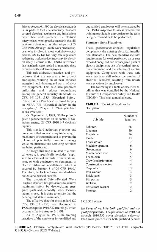
Prior to August 6, 1990 the electrical standardsin Subpart S of the General Industry Standardscovered electrical equipment and installationsrather than work practices. The electricalsafety-related work practice standards that didexist were distributed in other subparts of 29CFR 1910. Although unsafe work practices ap-pear to be involved in most workplace electro-cutions, OSHA has had very few regulationsaddressing work practices necessary for electri-cal safety. Because of this, OSHA determinedthat standards were needed to minimize thesehazards and the risk to employees.
This rule addresses practices and pro-cedures that are necessary to protectemployees working on or near exposedenergized and deenergized parts of elec-tric equipment. This rule also promotesuniformity and reduces redundancyamong the general industry standards. 29CFR 1910.331-.335 “Electrical Safety-Related Work Practices” is based largelyon NFPA 70E “Electrical Safety in theworkplace,” Chapter I “Safety-RelatedWork Practices.”
On September 1, 1989, OSHA promul-gated a generic standard on the control of haz-ardous energy, 29 CFR 1910.147 (lockout/tagout).
This standard addresses practices andprocedures that are necessary to deenergizemachinery or equipment and to prevent therelease of potentially hazardous energywhile maintenance and servicing activitiesare being performed.
Although this rule is related to electri-cal energy, it specifically excludes “expo-sure to electrical hazards from work on,near, or with conductors or equipment inelectric utilization installations, which iscovered by Subpart S of 29 CFR 1910.”Therefore, the lockout/tagout standard doesnot cover electrical hazards.
The Electrical Safety-Related WorkPractice standard has provisions to achievemaximum safety by deenergizing ener-gized parts and, secondly, when lockout/tagout is used, it is done to ensure that thedeenergized state is maintained.
The effective date for this standard (29CFR 1910.331-.335) was December 4,1990, except for 1910.332 (training), whichbecame effective August 6, 1991.
As of August 6, 1991, the trainingpractices of the employer for qualified and
unqualified employees will be evaluated bythe OSHA inspector to assess whether thetraining provided is appropriate to the tasksbeing performed or to be performed.
Summary (from Preamble):
These performance-oriented regulationscomplement the existing electrical installa-tion standards. The new standard includesrequirements for work performed on or nearexposed energized and deenergized parts ofelectric equipment; use of electrical protec-tive equipment; and the safe use of electricequipment. Compliance with these safework practices will reduce the number ofelectrical accidents resulting from unsafework practices by employees.
The following is a table of electrical fa-talities that was compiled by the NationalInstitute of Occupational Safety and Health(NIOSH). This is an annual average.
1910.331 Scope
(a) Covered work by both qualified and un-qualified persons. The provisions of 1910.331through 1910.335 cover electrical safety-re-lated work practices for both qualified persons
6.48 CHAPTER SIX
TABLE 4 Electrical Fatalities byOccupation
Number ofJob title fatalities
Laborer 28Lineman 20Electrician 16Painter 13Truck driver 7Machine operator 6Groundman 6Maintenance man 5Technician 5Crew leader/foreman 4Construction worker 4Carpenter 3Iron worker 3Brick layer 3Bill poster 3Welders 2Restaurant worker 2Fireman 2
FIGURE 6.2 Electrical Safety-Related Work Practices (OSHA-CFR, Title 29, Part 1910, Paragraphs331–335). (Courtesy OSHA Web site.)
(those who have training in avoiding the elec-trical hazards of working on or near exposedenergized parts)...
“On” or “near” is mentioned here and willbe mentioned throughout this subpart. Thedefinition of “on” is actual contact with thecircuit or part (involving either direct con-tact or contact by means of tools or material);“near” however needs further explanation.“Near” is when a person is near enough tothe energized circuits or parts to be exposedto any hazards they present.
More plainly stated; If a person is withinreaching, stumbling, or falling distance of anenergized circuit or part or close enough tothe energized parts that he/she could contactthese parts with any part of their body orwith any conductive object he/she is han-dling, that person is doing energized work.
...and unqualified persons (those with little orno such training) working on, near, or with thefollowing installations:
(1) Premises wiring. Installations of elec-tric conductors and equipment within or on build-ings or other structures, and on other premisessuch as yards, carnival, parking, and other lots,and industrial substations;
(2) Wiring for connection to supply. In-stallations of conductors that connect to thesupply of electricity; and
(3) Other wiring. Installations of otheroutside conductors on the premises.
Any wiring system that has been installedin accordance with the NEC and OSHASubpart S “Electrical Standard”).
(4) Optical fiber cable. Installations of op-tical fiber cable where such installations aremade along with electric conductors.
There are several types of optical fibercable that contain noncurrent-carrying con-ductive members such as metallic strengthmembers and metallic vapor barriers.
Note: See 1910.399 for the definition of“qualified person.” See 1910.332 for trainingrequirements that apply to qualified and un-qualified persons.
According to the National Electrical Code(NEC) and OSHA 29 CFR 1910.399, aqualified person is “one that is familiarwith the construction and operation of theequipment and the hazards involved.”
OSHA states that qualified persons areintended to be only those who are well ac-
quainted with and thoroughly conversant inthe electric equipment and electrical hazardsinvolved with the work being performed.
Definitions applicable to this subpartfor a qualified person;
“Note 1: Whether an employee is consideredto be a qualified person will depend on vari-ous circumstances in the workplace. It is pos-sible and, in fact, likely for an individual to beconsidered qualified with regard to certainequipment in the workplace, but unqualifiedas to other equipment.”
In other words just because a person is ajourneyman, master or 1st class electriciandoes not mean he is qualified on all systemsand equipment.
Example: If a new piece of equipment isinstalled and the electrician is not familiarwith the construction, operation and haz-ards involved, then he/she is unqualified asto that equipment.
Note 2: An employee who is undergoingon-the-job training and who, in the courseof such training, has demonstrated an abil-ity to perform duties safely at his or herlevel of training and who is under the directsupervision of a qualified person is consid-ered to be a qualified person for the perfor-mance of those duties.”
There are numerous references through-out this subpart that state “qualified personsonly”. For example: Only qualified personsare allowed to work on or near energized cir-cuits or parts; a qualified person shall operateequipment to verify it cannot restart; a quali-fied person shall use test equipment to testthe circuit to verify it is de-energized; onlyqualified persons may perform testing workon electric circuits, etc. Therefore, if a personwere not qualified he/she could never be-come qualified because they could never doanything. This is the reason for Note 2,quoted above. A person can become quali-fied if working under the direct supervisionof a qualified person.
(b) Other covered work by unqualified per-sons. The provisions of 1910.331 through1910.335 also cover work performed by un-qualified persons on, near, or with the installa-tions listed in paragraphs (c)(1) through (c)(4)of this section.
(c) Excluded work by qualified persons. Theprovisions of 1910.331 through 1910.335
REGULATORY AND LEGAL SAFETY REQUIREMENTS AND STANDARDS 6.49
FIGURE 6.2 (Continued)
do not apply to work performed by qualifiedpersons on or directly associated with the fol-lowing installations:
(1) Generation, transmission, and distrib-ution installations. Installations for the gener-ation, control, transformation, transmission, anddistribution of electric energy (including com-munication and metering) located in buildingsused for such purposes or located outdoors.
OSHA (D of C) states that “Work on thespecified electrical installations is excluded,but work on the other electric equipment inthe buildings is not excluded.”
Note 1: Work on or directly associated withinstallations of utilization equipment used forpurposes other than generating, transmitting, ordistributing electric energy (such as installa-tions which are in office buildings, warehouses,garages, machine shops, or recreational build-ings, or other utilization installations which arenot an integral part of a generating installation,substation, or control center) is covered underparagraph (a)(1) of this section.
Note 2: Work on or directly associatedwith generation, transmission, or distributioninstallations includes:
1) Work performed directly on such installa-tions, such as repairing overhead or undergrounddistribution lines or repairing a feed-water pumpfor the boiler in a generating plant.
2) Work directly associated with such in-stallations, such as line-clearance tree trim-ming and replacing utility poles.
3) Work on electric utilization circuits in agenerating plant provided that:
A) Such circuits are commingled with instal-lations of power generation equipment or cir-cuits, and
B) The generation equipment or circuitspresent greater electrical hazards than thoseposed by the utilization equipment or circuits(such as exposure to higher voltages or lack ofovercurrent protection).
(2) Communications installations. Instal-lations of communication equipment to the ex-tent that the work is covered under 1910.268.
(3) Installations in vehicles. Installationsin ships, watercraft, railway rolling stock, air-craft, or automotive vehicles other than mobilehomes and recreational vehicles.
The OSHA Federal Register for ships andwatercraft (marine) is 29 CFR 1915.
(4) Railway installations. Installations ofrailways for generation, transformation, trans-
mission, or distribution of power used exclu-sively for operation of rolling stock or installa-tions of railways used exclusively for signalingand communication purposes.
1910.332 Training
(a) Scope. The training requirements con-tained in this section apply to employees whoface a risk of electric shock that is not reducedto a safe level by the electrical installation re-quirements of 1910.303 through 1910.308.
(NFPA 70E, Section 1.A) “Safety Training.Employees shall be trained in the safety-related work practices, safety procedures, andother personnel safety requirements in thisstandard that pertain to their respective job as-signments.
Employees shall not be permitted towork in an area where they are likely to en-counter electrical hazards unless they havebeen trained to recognize and avoid the elec-trical hazards to which they will be exposed.
For the purpose of this standard, anelectrical hazard is a recognizable danger-ous electrical condition. Electrical condi-tions such as exposed energized parts andunguarded electric equipment which maybecome energized unexpectedly are exam-ples of electrical hazards.”
(Preamble) “Employees are required tobe trained in the safety-related work prac-tices of this standard, as well as any otherpractices necessary for safety from electri-cal hazards.”
This would include systems and equip-ment that are enclosed or otherwise renderedinaccessible to employees or are at voltagesless than 50 volts to ground. However, whenan enclosure cover has been removed oropened for inspection or maintenance of theenergized components, the employee faces arisk of electric shock and the requirementsof 1910.331 through 1910.335 wouldapply.
(D of C) “All employees who face arisk of electric shock, burns, or other re-lated injuries, not reduced to a safe level bythe installation safety requirements of Sub-part S, must be trained in safety-relatedwork practices required by 29 CFR1910.331-.335.”
(Preamble) “The final rule does notcontain provisions addressing the qualifica-tions of trainers or the demonstration of ef-fectiveness of the training.”
6.50 CHAPTER SIX
FIGURE 6.2 (Continued)
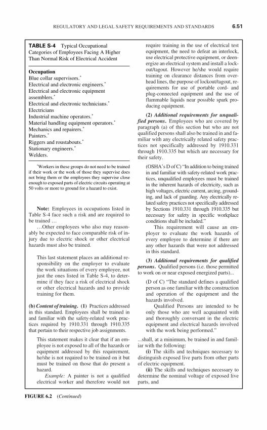
Note: Employees in occupations listed inTable S-4 face such a risk and are required tobe trained …
…Other employees who also may reason-ably be expected to face comparable risk of in-jury due to electric shock or other electricalhazards must also be trained.
This last statement places an additional re-sponsibility on the employer to evaluatethe work situations of every employee, notjust the ones listed in Table S-4, to deter-mine if they face a risk of electrical shockor other electrical hazards and to providetraining for them.
(b) Content of training. (1) Practices addressedin this standard. Employees shall be trained inand familiar with the safety-related work prac-tices required by 1910.331 through 1910.335that pertain to their respective job assignments.
This statement makes it clear that if an em-ployee is not exposed to all of the hazards orequipment addressed by this requirement,he/she is not required to be trained on it butmust be trained on those that do present ahazard.
Example: A painter is not a qualifiedelectrical worker and therefore would not
require training in the use of electrical testequipment, the need to defeat an interlock,use electrical protective equipment, or deen-ergize an electrical system and install a lock-out/tagout. However he/she would requiretraining on clearance distances from over-head lines, the purpose of lockout/tagout, re-quirements for use of portable cord- andplug-connected equipment and the use offlammable liquids near possible spark pro-ducing equipment.
(2) Additional requirements for unquali-fied persons. Employees who are covered byparagraph (a) of this section but who are notqualified persons shall also be trained in and fa-miliar with any electrically related safety prac-tices not specifically addressed by 1910.331through 1910.335 but which are necessary fortheir safety.
(OSHA’s D of C) “In addition to being trainedin and familiar with safety-related work prac-tices, unqualified employees must be trainedin the inherent hazards of electricity, such ashigh voltages, electric current, arcing, ground-ing, and lack of guarding. Any electrically re-lated safety practices not specifically addressedby Sections 1910.331 through 1910.335 butnecessary for safety in specific workplaceconditions shall be included.”
This requirement will cause an em-ployer to evaluate the work hazards ofevery employee to determine if there areany other hazards that were not addressedin this standard.
(3) Additional requirements for qualifiedpersons. Qualified persons (i.e. those permittedto work on or near exposed energized parts)...
(D of C) “The standard defines a qualifiedperson as one familiar with the constructionand operation of the equipment and thehazards involved.
Qualified Persons are intended to beonly those who are well acquainted withand thoroughly conversant in the electricequipment and electrical hazards involvedwith the work being performed.”
...shall, at a minimum, be trained in and famil-iar with the following:
(i) The skills and techniques necessary todistinguish exposed live parts from other partsof electric equipment.
(ii) The skills and techniques necessary todetermine the nominal voltage of exposed liveparts, and
REGULATORY AND LEGAL SAFETY REQUIREMENTS AND STANDARDS 6.51
TABLE S-4 Typical OccupationalCategories of Employees Facing A HigherThan Normal Risk of Electrical Accident
OccupationBlue collar supervisors.*
Electrical and electronic engineers.*
Electrical and electronic equipmentassemblers.*
Electrical and electronic technicians.*
ElectriciansIndustrial machine operators.*
Material handling equipment operators.*
Mechanics and repairers.*
Painters.*
Riggers and roustabouts.*
Stationary engineers.*
Welders.
*Workers in these groups do not need to be trainedif their work or the work of those they supervise doesnot bring them or the employees they supervise closeenough to exposed parts of electric circuits operating at50 volts or more to ground for a hazard to exist.
FIGURE 6.2 (Continued)
(iii) The clearance distances specified in1910.333(c) andthe corresponding voltages to which the quali-fied person will be exposed.
Note 1: For the purposes of 1910.331through 1910.335, a person must have the train-ing required by paragraph (b)(3) of this sectionin order to be considered a qualified person.
Note 2: Qualified persons whose work onenergized equipment involves either directcontact or contact by means of tools or materi-als must also have the training needed to meet1910.333(C)(2).
(c) Type of training. The training required bythis section shall be of the classroom or on-the-job type. The degree of training provided shallbe determined by the risk to the employee.
In most cases, both classroom and on-the-job type training would be needed.
(D of C) “The failure to train ‘qualified’and ‘unqualified’ employees, as requiredfor their respective classifications, shallnormally be cited as a serious violation.”
1910.333 Selection and Use of WorkPractices
(Preamble) “The basic intent of 1910.333 isto require employers to take one of three op-tions to protect employees working on elec-tric circuits and equipment: (1) Deenergizethe equipment involved and lockout its dis-connecting means; or (2) deenergize theequipment and tag the disconnecting means,if the employer can demonstrate that taggingis as safe as locking; or (3) work the equip-ment energized if the employer can demon-strate that it is not feasible to deenergize it.
Paragraph (a) of 1910.333 sets forthgeneral requirements on the selection anduse of work practices. The requirements ofthis paragraph mainly address accidentswhich involve the hazards of exposure tolive parts of electric equipment. A deener-gized part is obviously safer than an ener-gized one. Because the next best method ofprotecting an employee working on exposedparts of electric equipment (the use of per-sonal protective equipment) would continueto expose that employee to a risk of injuryfrom electric shock, 1910.333(a) makesequipment deenergizing the primary methodof protecting employees.
Under certain conditions, however,deenergizing need not be employed. Em-
ployees may be allowed to work on or nearexposed energized parts as allowed under1910.333(a)(1).”
(a) General. Safety-related work practicesshall be employed to prevent electric shock orother injuries resulting from either direct or in-direct electrical contacts, when work is per-formed near or on equipment or circuits whichare or may be energized. The specific safety-re-lated work practices shall be consistent withthe nature and extent of the associated electri-cal hazards.
(D of C) “1910.333(a)(1) requires that liveparts be deenergized before a potentiallyexposed employee works on or near them.OSHA believes that this is the preferredmethod for protecting employees fromelectrical hazards. The employer is permit-ted to allow employees to work on or nearexposed live parts only:
(1) If the employer can demonstrate thatdeenergizing introduces additional orincreased hazards (see Note 1 below),
(2) If the employer can demonstrate thatdeenergizing is infeasible due to equip-ment design or operational limitations(see Note 2 below).”
(1) Deenergized parts. Live parts to whichan employee may be exposed shall be de-energized before the employee works on or nearthem, unless the employer can demonstrate thatdeenergizing introduces additional or increasedhazards, or is infeasible due to equipment designor operational limitations. Live parts that operateat less than 50 volts to ground need not be deener-gized if there will be no increased exposure toelectrical burns or to explosion due to electric arcs.
Note 1: Examples of increased or addi-tional hazards include interruption of life sup-port equipment, deactivation of emergencyalarm systems, shutdown of hazardous locationventilation equipment, or removal of illumina-tion for an area.
Note 2: Examples of work that may beperformed on or near energized circuit partsbecause of infeasibility due to equipment de-sign or operational limitations include testingof electric circuits that can only be performedwith the circuit energized and work on circuitsthat form an integral part of a continuous in-dustrial process in a chemical plant that wouldotherwise need to be completely shut down inorder to permit work on one circuit or piece ofequipment.
6.52 CHAPTER SIX
FIGURE 6.2 (Continued)

Note 3: Work on or near deenergized partsis covered by paragraph (b) of this section.
(D of C) “Under 1910.333(a)(2) if the em-ployer does not deenergize (under the con-ditions permitted in 1910.333(a)(1)), thensuitable safe work practices for the condi-tions under which the work is to be per-formed shall be included in the writtenprocedures and strictly enforced. Thesework practices are given in 1910.333(c)and 1910.335.
Only qualified persons shall be allowedto work on energized parts or equipment.”
(2) Energized parts. If the exposed live partsare not deenergized (i.e., for reasons of increasedor additional hazards or infeasibility), othersafety-related work practices shall be used to pro-tect employees who may be exposed to the elec-trical hazards involved. Such work practices shallprotect employees against contact with energizedcircuit parts directly with any part of their body orindirectly through some other conductive object.The work practices that are used shall be suitablefor the conditions under which the work is to beperformed and for the voltage level of the ex-posed electric conductors or circuit parts. Specificwork practice requirements are detailed in para-graph (c) of this section.
(D of C) “If the employer does not deener-gize (under the conditions permitted in1910.333(a)(1)), then suitable safe workpractices for the conditions under which thework is to be performed shall be included inthe written procedure and strictly enforced.”
(b) Working on or near exposed deenergizedparts. (1) Application. This paragraph ap-plies to work on exposed deenergized parts ornear enough to them to expose the employee toany electrical hazard they present. Conductorsand parts of electric equipment that have beendeenergized but have not been locked out ortagged in accordance with paragraph (b) of thissection shall be treated as energized parts, andparagraph (c) of this section applies to work onor near them.
(D of C) “Circuits parts that cannot bedeenergized using the procedures outlinedin 1910.333(b)(2) must be treated as ener-gized, regardless of whether the parts areturned off and assumed to be deenergized.”
The lockout/tagout requirements of thisregulation were derived from the existingANSI and NFPA standards.
(Preamble) “The NFPA 70E require-ments were intended to apply any time workis performed on or near deenergized circuitparts or equipment in any situation whichpresents a danger that the circuit parts orequipment might become unexpectedly en-ergized. Thus, the NFPA provisions notonly address the hazard of contact with en-ergized parts, but also cover other hazardswhich are presented by start-up of equip-ment during maintenance operations. Thisis expressed in NFPA 70E, Part II, Section1.B, second paragraph, which states:
‘Where the work to be performed re-quires employees to work on or near ex-posed circuit parts or equipment, and thereis danger of injury due to electric shock,unexpected movement of equipment, orother electrical hazards, the circuit partsand equipment that endanger the employ-ees shall be deenergized and locked out ortagged out in accordance with the policiesand procedures specified.’
In contrast to this, OSHA Subpart Sstandard is intended to cover employee ex-posure to electrical hazards which mightoccur from the unexpected energizing ofthe circuit parts and does not cover otherequipment-related hazards which do not in-volve exposed live parts. Thus, the SubpartS standard will protect the electrician work-ing on a circuit but does not address a me-chanic working on the mechanical parts ofan electrically powered machine. Thegeneric lockout standard, 1910.147, coversthe hazards of unexpected activation or en-ergization of machinery or equipment dur-ing servicing or maintenance activities.”
(2) Lockout and Tagging. While any em-ployee is exposed to contact with parts of fixedelectric equipment or circuits which have beendeenergized, the circuits energizing the partsshall be locked out or tagged or both in accor-dance with the requirements of this paragraph.The requirements shall be followed in the orderin which they are presented (i.e., paragraph(b)(2)(i) first, then paragraph (b)(2)(ii), etc.).
Note 1: As used in this section, fixed equip-ment refers to equipment fastened in place orconnected by permanent wiring methods.
Note 2: Lockout and tagging proceduresthat comply with paragraphs (c) through (f) of1910.147 will also be deemed to comply withparagraph (b)(2) of this section provided that:
(1) The procedures address the electricalsafety hazards covered by this Subpart; and
REGULATORY AND LEGAL SAFETY REQUIREMENTS AND STANDARDS 6.53
FIGURE 6.2 (Continued)
(2) The procedures also incorporate the re-quirements of paragraphs (b)(2)(iii)(D) and(b)(2)(iv)(B) of this section.
(Preamble) “In comparing 1910.333(b)(2)with final 1910.147, OSHA determined thatthe generic lockout standard encompassed allthe lockout and tagging requirements con-tained in the electrical work practices with twoexceptions. First, the electrical standard moretightly restricted the use of tags without locksand called for additional protection when tagswere permitted. Secondly, the electrical workpractices contain specific requirements fortesting circuit parts for voltage before theycould be considered as deenergized.
OSHA believes that a lockout and tag-ging program which meets 1910 .147 will,with these two exceptions, provide protec-tion for servicing and maintenance involvingelectrical work and live parts. Accordingly,the final rule on electrical safety-relatedwork practices incorporates this finding.”
(D of C) “Only qualified persons mayplace and remove locks and tags.”
(Preamble) “OSHA has decided to ac-cept any lockout and tagging program thatconforms to 1910.147 if it also meets para-graphs 1910.333 (b)(2)(iii)(D) and (b)(2)(iv)(B). This will enable employers to use a sin-gle lockout and tagout program to cover allhazards addressed by these two standards, aslong as that program includes proceduresthat meet the two additional paragraphswhen exposure to electric shock is involved.
OSHA has limited the application of thelockout and tagging provisions to fixedequipment. Employees can safely work oncord-and plug-connected, portable and sta-tionary equipment which is disconnectedfrom the circuit. Generally, such equipmentis returned to a maintenance shop for repair,and the danger of accidental energizing ofequipment parts is eliminated in most cases.However, in 1910.147 (the generic lockout/tagout standard) it states: “This standard doesnot apply to the following:
(A) Work on cord- and plug-connectedequipment for which exposure to the hazardsof unexpected energization or start-up of theequipment is controlled by the unplugging ofthe equipment from the energy source and bythe plug being under the exclusive control ofthe employee performing the servicing ormaintenance.”
This requirement clearly states that ifthe plug is not under the “exclusive con-
trol” of the employee, it must be locked outor tagged out.
“The generic lockout standard (OSHA)and NFPA 70E’s lockout provisions containrequirements for lockout procedures to be inwriting.
OSHA believes that written proceduresare an important part of a successful lockoutand tagging program and that they should,therefore, be required. However, the finalelectrical standard lockout provisions arethemselves a step-by-step procedure forsafely deenergizing electrical circuits. Forthis reason, the final electrical work practicesstandard incorporates a requirement for em-ployers to maintain a copy of the lockoutprocedure outlined in 1910.333(b)(2) andmake it available for inspection by employ-ees and OSHA.”
(1910.147) The following is quotedfrom 1910.147(a)(3) Purpose: “(ii) Whenother standards in this part (meaning 1910)require the use of lockout or tagout, theyshall be used and supplemented by the pro-cedural and training requirements of thissection.” Therefore, the requirements of thegeneric standard (1910.147) also apply,along with the additional lockout and tagoutrequirements of this standard, for all electri-cal lockout or tagout situations.
(i) Procedures. The employer shall main-tain a written copy of the procedures outlinedin paragraph (b)(2) and shall make it availablefor inspection by employees and by the Assis-tant Secretary of Labor and his or her autho-rized representatives.
(D of C) “During walk around inspections,compliance officers shall evaluate anyelectrical related work being performed toascertain conformance with the employer’swritten procedures as required by 1910.333(b)(2)(i) and all safety-related work prac-tices in Sections 1910.333 through 1910.335.
A deficiency in the employer’s pro-gram that could contribute to a potential ex-posure capable of producing seriousphysical harm or death shall be cited as aserious violation.”
Note: The written procedures may be in theform of a copy of paragraph (b) of this section.
(ii) Deenergizing equipment. (A) Safeprocedures for deenergizing circuits and equip-ment shall be determined before circuits orequipment are deenergized.
6.54 CHAPTER SIX
FIGURE 6.2 (Continued)
1910.147(d)(1) states this requirementmuch more clearly, as follows:
“Preparation for shutdown. Before anauthorized or affected employee turns off amachine or equipment, the authorized em-ployee shall have knowledge of the type andmagnitude of the energy, the hazards of theenergy to be controlled, and the method ormeans to control the energy.”
(B) The circuits and equipment to beworked on shall be disconnected from all elec-tric energy sources....
There can be several electric energysources such as the power circuit, controlcircuit energized from a separate source,and interlocks from other devices. In thecase of a power circuit breaker there couldbe AC and/or DC sources for the trip coil,closing coil, spring charging motor, andany number of circuits that operate throughthe auxiliary contacts.
...Control circuit devices, such as push but-tons, selector switches, and interlocks, may notbe used as the sole means for deenergizing cir-cuits or equipment...
It is a good practice to turn a control deviceoff so the load will be removed prior to open-ing the disconnecting means. This practicewill reduce the risk of arcing in the deviceand a possible flash-over from phase-to-phase and/or phase-to-ground. These controldevices should also be locked and/or taggedbefore the main disconnecting means isopened.
If this is not done, the disconnectingmeans could be opened at the same time acontrol is turned to the on position resulting ina current level far beyond its rating. The fol-lowing example is used to further illustrate:
If the disconnect switch was rated for aload of 30 amperes, and the full load cur-rent was 24 amperes, and if the disconnectswitch were to be opened at the same timethe motor was being started, the discon-nect switch contacts would experience ap-proximately locked motor current which isabout six times the full load current or, inthis case, 144 amperes. In this case aflash-over from phase-to-phase and/orphase-to-ground would be very likely.This could cause the enclosure to explodeand injure the person who is switching thedevice.
...Interlocks for electric equipment may notbe used as a substitute for lockout and taggingprocedures.
(C) Stored electric energy which might en-danger personnel shall be released. Capacitorsshall be discharged and high capacitance elementsshall be short-circuited and grounded, if the storedelectric energy might endanger personnel.
Note: If the capacitors or associatedequipment are handled in meeting this require-ment, they shall be treated as energized.
(D) Stored non-electrical energy in devicesthat could reenergize electric circuit parts shallbe blocked or relieved to the extent that the cir-cuit parts could not be accidentally energizedby the device.
A good example of this would be chargedclosing springs on a power circuit breaker,or hydraulic or pneumatic pressure in an oilcircuit breaker operating mechanism.
(iii) Application of locks and tags. (A) Alock and a tag shall be placed on each disconnect-ing means used to deenergize circuits and equip-ment on which work is to be performed, except asprovided in paragraphs (b)(2)(iii)(C) and(b)(2)(iii)(E) of this section. The lock shall be at-tached so as to prevent persons from operating thedisconnecting means unless they resort to undueforce or the use of tools.
1910.147 states, “(C) Substantial, (1) Lock-out devices. Lockout devices shall be sub-stantial enough to prevent removal withoutthe use of excessive force or unusual tech-niques, such as with the use of bolt cuttersor other metal cutting tools.”
(B) Each tag shall contain a statement pro-hibiting unauthorized operation of the discon-necting means and removal of the tag.
1910.147 states, “Tagout devices shallwarn against hazardous conditions if themachine or equipment is energized andshall include a legend such as the follow-ing: Do Not Start, Do Not Open, Do NotClose, Do Not Energize, Do Not Operate.”
(C) If a lock cannot be applied, or if the em-ployer can demonstrate that tagging procedureswill provide a level of safety equivalent to thatobtained by the use of a lock, a tag may be usedwithout a lock.
(D) A tag used without a lock, as permittedby paragraph (b)(2)(iii)(C) of this section, shallbe supplemented by at least one additional
REGULATORY AND LEGAL SAFETY REQUIREMENTS AND STANDARDS 6.55
FIGURE 6.2 (Continued)
safety measure that provides a level of safetyequivalent to that obtained by use of a lock.Examples of additional safety measures in-clude the removal of an isolating circuit ele-ment, blocking of a controlling switch, oropening of an extra disconnecting device.
(Preamble) “Because a person could operatethe disconnecting means before reading orrecognizing the tag, the standard also re-quires that, where tags are used, one or moreadditional safety measures be taken to pro-vide added safety. The additional measuresused must either: (1) Ensure that the closingof the tagged single switch would not reener-gize the circuit on which employees areworking or (2) virtually prevent the acciden-tal closing of the disconnecting means. Thefollowing examples from the record illustrateprotective techniques that are commonlyused to supplement tags and protect workers:
(1) The removal of a fuse or fuses for acircuit.
(2) The removal of a draw-out circuitbreaker from a switchboard (i.e., rack-ing out the breaker).
(3) The placement of a blocking mechanismover the operating handle of a disconnect-ing means so that the handle is blockedfrom being placed in the closed position.
(4) The opening of a switch (other than thedisconnecting means) which also opensthe circuit between the source of powerand the exposed parts on which work isto be performed.
(5) The opening of a switch for a controlcircuit that operates a disconnect that isitself open and disconnected from thecontrol circuit or is otherwise disabled.
(6) Grounding of the circuit upon whichwork is to be performed.
The additional safety measure is neces-sary because, at least for electrical discon-necting means, tagging alone is significantlyless safe than locking out. A disconnectingmeans could be closed by an employee whohas failed to recognize the purpose of thetag. The disconnect could also be closedaccidentally.”
It should be noted that, in addition to themeasures noted in the preamble, there areother measures that can be taken, such as:
(1) Removing the control power fuses.(2) Lifting the wires from the circuit breaker,
disconnect, or contactor terminals orfrom a terminal.
It should also be noted that these addi-tional measures could also be used in thecase of a lockout, as an additional safetymeasure.
(Preamble) “Any measure or combina-tion of measures, that will protect employ-ees as well as the application of a lock, canbe used to supplement the tagging of the dis-connecting means. In determining whetheran individual employer’s ‘tagging-only’program provides safety equivalent to alock, OSHA will consider factors such as:
(1) The safety record under the employer’stagging program;
(2) Whether the tagged disconnecting meansare accessible to qualified persons only;
(3) Whether the tag and its attachmentmechanism clearly identify the discon-necting means that is open and effec-tively inhibit reenergizing the electriccircuit (for example, when a tag is usedon an energy isolating device that is ca-pable of being locked out, the tag mustbe attached at the same location that thelock would have been attached); and
(4) Whether employees are thoroughly fa-miliar with the tagging procedures, es-pecially their duties and responsibilitieswith respect to the procedures and themeaning and significance of the tagsused with the procedure.”
It is also a requirement of 1910.147 thatif the tag is used in the place of a lock thetag attachment means shall be non-reusable, attachable by hand, self-locking,and non-releasable and have a pull strengthof no less than 50 pounds and be at leastequivalent to an all environment tolerantnylon cable tie.
It is also a requirement that if the en-ergy isolating device is not capable ofbeing locked out, the tag must be attachedto or immediately adjacent to the device insuch a manner that it would be obvious toanyone attempting to operate the device,that it is tagged out.
(E) A lock may be placed without a tagonly under the following conditions:
1 Only one circuit or piece of equipmentis deenergized, and
2 The lockout period does not extend be-yond the work shift, and
3 Employees exposed to the hazards as-sociated with reenergizing the circuit or equip-ment are familiar with this procedure.
6.56 CHAPTER SIX
FIGURE 6.2 (Continued)
(iv) Verification of deenergized condition.The requirements of this paragraph shall bemet before any circuits or equipment can beconsidered and worked as deenergized.
(D of C) “Verification of deenergization ismandatory. This verification must be doneby a “qualified person.” This is done by fol-lowing the requirements of paragraph (A)and (B) of this section.”
(A) A qualified person shall operate theequipment operating controls or otherwise ver-ify that the equipment cannot be restarted.
(B) A qualified person shall use testequipment to test the circuit elements andelectrical parts of equipment to which em-ployees will be exposed and shall verify thatthe circuit elements and equipment parts aredeenergized. The test shall also determine ifany energized condition exists as a result ofinadvertently induced voltage or unrelatedvoltage backfeed even though specific partsof the circuit have been deenergized and pre-sumed to be safe....
A current one-line diagram can be a veryuseful tool to verify that the right circuit wasdeenergized, that all electrical sources weredeenergized, and will identify all possiblebackfeed sources.
The key to this is that the one-line dia-gram must be current or correct.
...If the circuit to be tested is over 600 volts,nominal, the test equipment shall be checkedfor proper operation immediately before andimmediately after this test.
(Preamble) “Voltages over 600 volts aremore likely than lower voltages to cause testequipment itself to fail, leading to false in-dications of no-voltage conditions. To pre-vent accidents resulting from such failure oftest equipment, the final standard requireschecking operation of the test equipmentimmediately before and after use, if volt-ages over 600 volts are involved.”
(D of C) “Testing instruments andequipment shall be visually inspected for ex-ternal defects or damage before being usedto determine deenergization according to therequirements of 29 CFR 1910.334(c)(2).”
There is evidence of electrical injuriesand fatalities with voltages as low as 50volts. Because of this hazard, it is a goodpractice to verify the proper operation of thetest equipment on these lower voltages aswell as the requirement for over 600 volts.
(v) Reenergizing equipment. These re-quirements shall be met, in the order given, be-fore circuits or equipment are reenergized,even temporarily.
(A) A qualified person shall conduct testsand visual inspections, as necessary, to verifythat all tools, electrical jumpers, shorts, grounds,and other such devices have been removed, sothat the circuits and equipment can be safelyenergized.
(B) Employees exposed to the hazards as-sociated with reenergizing the circuit or equip-ment shall be warned to stay clear of circuitsand equipment.
(C) Each lock and tag shall be removed bythe employee who applied it or under his or herdirect supervision. However, if this employeeis absent from the workplace, then the lock ortag may be removed by a qualified person des-ignated to perform this task provided that:
1 The employer ensures that the em-ployee who applied the lock or tag is not avail-able at the workplace, and
An additional requirement, found in1910.147 for energy control, is that everyreasonable effort be made to contact theemployee before locks or tags are removed.
2 The employer ensures that the em-ployee is aware that the lock or tag has been re-moved before he or she resumes work at thatworkplace.
(Preamble) “This requirement ensures thatlocks and tags are removed with the fullknowledge of the employee who appliedthem. Without such a requirement, it islikely that a lock or a tag could be removedby persons who are not responsible for thelockout, endangering employees workingon the ‘deenergized parts.’ This provisionalso allows for removal of locks and tags ifthe employee who applied them is absentfrom the workplace, under conditions likethose in the exception to 1910.147(e)(3).”
(D) There shall be a visual determinationthat all employees are clear of the circuits andequipment.
Often this would require more than one per-son, i.e., one at the equipment and one at thedisconnecting means, both using two-wayradios or other effective communicationsmethods.
(c) Working on or near exposed energizedparts. (1) Application. This paragraph applies
REGULATORY AND LEGAL SAFETY REQUIREMENTS AND STANDARDS 6.57
FIGURE 6.2 (Continued)
to work performed on exposed live parts (in-volving either direct contact or by means oftools or materials) or near enough to them foremployees to be exposed to any hazard theypresent.
All of 1910.333(c) addresses the requiredenergized work procedures and employeequalification requirements.
(2) Work on energized equipment. Onlyqualified persons may work on electric circuitparts or equipment that have not been deener-gized under the procedures of paragraph (b) ofthis section. Such persons shall be capable ofworking safely on energized circuits and shallbe familiar with the proper use of special pre-cautionary techniques, personal protectiveequipment, insulating and shielding materials,and insulated tools.
(3) Overhead lines. If work is to be per-formed near overhead lines, the lines shall bedeenergized and grounded, or other protectivemeasures shall be provided before work isstarted. If the lines are to be deenergized,arrangements shall be made with the person ororganization that operates or controls the elec-tric circuits involved to deenergize and groundthem. If protective measures, such as guarding,isolating, or insulating, are provided, these pre-cautions shall prevent employees from contact-ing such lines directly with any part of theirbody or indirectly through conductive materi-als, tools, or equipment.
(D of C) “This standard for ElectricalSafety-Related Work Practices can be ap-plied with respect to electrical hazards re-lated to any size, utilization, or configurationof overhead power lines in general industry;e.g., residential power lines, remotely lo-cated overhead power lines, temporarilyrigged overhead power lines, and overheadpower lines along streets and alleys.”
It should also be noted that overheadpower lines and bus structures in substationsand switchyards present the same hazard asall other overhead power lines. Therefore thesame work practices should be used whenwork is being performed near these overheadsystems.
(D of C) “Working On or Near Over-head Power Lines;
(a) OSHA believes that the preferredmethod of protecting employees work-ing near overhead power lines is to
deenergize and ground the lines whenwork is to be performed near them.
(b) In addition to other operations, thisstandard also applies to tree trimmingoperations performed by tree workerswho are not qualified persons. In thisrespect the exclusion in 1910.331(c)(1)applies only to qualified persons per-forming line-clearance tree trimming(trimming trees that are closer than 10feet to overhead power lines).
(c) This standard does not prohibit workerswho are not qualified persons fromworking in a tree that is closer than 10feet to power lines so long as that per-son or any object he or she may beusing, does not come within 10 feet of apower line. However, it would requirequalified persons to perform the work ifthe worker or any object he or she maybe using will come within 10 feet of anexposed energized part or if a branchbeing cut may be expected to comewithin 10 feet of an exposed energizedpart while falling from the tree.
(d) The purpose for the approach distancerequirements is to prevent contact with,and/or arcing, from energized overheadpower lines. The approach distance ap-plies to tools used by employees as wellas the employees them-selves. Table S-5calls for the approach distances forqualified persons only. Unqualified per-sons are required to adhere to the 10foot minimum.”
Note: The work practices used by qualifiedpersons installing insulating devices on over-head power transmission or distribution lines arenot covered by 1910.332 through 1910.335.Under paragraph (c)(2) of this section, unquali-fied persons are prohibited from performing thistype of work.
Qualified persons installing insulating equip-ment on or deenergizing and grounding thelines and line-clearance tree trimming arecovered under 1910.269, “Electric PowerGeneration, Transmission, and Distribution”Federal Register.
(i) Unqualified persons. (A) When an un-qualified person is working in an elevated posi-tion near overhead lines, the location shall besuch that the person and the longest conductiveobject he or she may contact cannot come
6.58 CHAPTER SIX
FIGURE 6.2 (Continued)
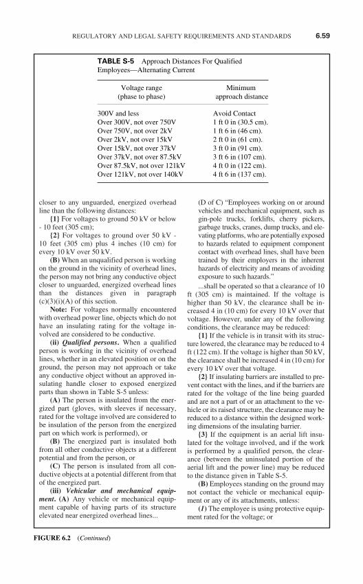
closer to any unguarded, energized overheadline than the following distances:
1 For voltages to ground 50 kV or below- 10 feet (305 cm);
2 For voltages to ground over 50 kV -10 feet (305 cm) plus 4 inches (10 cm) forevery 10 kV over 50 kV.
(B) When an unqualified person is workingon the ground in the vicinity of overhead lines,the person may not bring any conductive objectcloser to unguarded, energized overhead linesthan the distances given in paragraph(c)(3)(i)(A) of this section.
Note: For voltages normally encounteredwith overhead power line, objects which do nothave an insulating rating for the voltage in-volved are considered to be conductive.
(ii) Qualified persons. When a qualifiedperson is working in the vicinity of overheadlines, whether in an elevated position or on theground, the person may not approach or takeany conductive object without an approved in-sulating handle closer to exposed energizedparts than shown in Table S-5 unless:
(A) The person is insulated from the ener-gized part (gloves, with sleeves if necessary,rated for the voltage involved are considered tobe insulation of the person from the energizedpart on which work is performed), or
(B) The energized part is insulated bothfrom all other conductive objects at a differentpotential and from the person, or
(C) The person is insulated from all con-ductive objects at a potential different from thatof the energized part.
(iii) Vehicular and mechanical equip-ment. (A) Any vehicle or mechanical equip-ment capable of having parts of its structureelevated near energized overhead lines...
(D of C) “Employees working on or aroundvehicles and mechanical equipment, such asgin-pole trucks, forklifts, cherry pickers,garbage trucks, cranes, dump trucks, and ele-vating platforms, who are potentially exposedto hazards related to equipment componentcontact with overhead lines, shall have beentrained by their employers in the inherenthazards of electricity and means of avoidingexposure to such hazards.”...shall be operated so that a clearance of 10
ft (305 cm) is maintained. If the voltage ishigher than 50 kV, the clearance shall be in-creased 4 in (10 cm) for every 10 kV over thatvoltage. However, under any of the followingconditions, the clearance may be reduced:
1 If the vehicle is in transit with its struc-ture lowered, the clearance may be reduced to 4ft (122 cm). If the voltage is higher than 50 kV,the clearance shall be increased 4 in (10 cm) forevery 10 kV over that voltage.
2 If insulating barriers are installed to pre-vent contact with the lines, and if the barriers arerated for the voltage of the line being guardedand are not a part of or an attachment to the ve-hicle or its raised structure, the clearance may bereduced to a distance within the designed work-ing dimensions of the insulating barrier.
3 If the equipment is an aerial lift insu-lated for the voltage involved, and if the workis performed by a qualified person, the clear-ance (between the uninsulated portion of theaerial lift and the power line) may be reducedto the distance given in Table S-5.
(B) Employees standing on the ground maynot contact the vehicle or mechanical equip-ment or any of its attachments, unless:
(1) The employee is using protective equip-ment rated for the voltage; or
REGULATORY AND LEGAL SAFETY REQUIREMENTS AND STANDARDS 6.59
TABLE S-5 Approach Distances For QualifiedEmployees—Alternating Current
Voltage range Minimum(phase to phase) approach distance
300V and less Avoid ContactOver 300V, not over 750V 1 ft 0 in (30.5 cm).Over 750V, not over 2kV 1 ft 6 in (46 cm).Over 2kV, not over 15kV 2 ft 0 in (61 cm).Over 15kV, not over 37kV 3 ft 0 in (91 cm).Over 37kV, not over 87.5kV 3 ft 6 in (107 cm).Over 87.5kV, not over 121kV 4 ft 0 in (122 cm).Over 121kV, not over 140kV 4 ft 6 in (137 cm).
FIGURE 6.2 (Continued)
(2) The equipment is located so that nouninsulated part of its structure (that portion ofthe structure that provides a conductive path toemployees on the ground) can come closer tothe line than permitted in paragraph (c)(3)(iii)of this section.
(C) If any vehicle or mechanical equipmentcapable of having parts of its structure elevatednear energized overhead lines is intentionallygrounded, employees working on the ground nearthe point of grounding may not stand at the ground-ing location whenever there is a possibility of over-head line contact. Additional precautions, such asthe use of barricades or insulation, shall be taken toprotect employees from hazardous ground poten-tials, depending on earth resistivity and fault cur-rents, which can develop within the first few feet ormore outward from the grounding point.
(4) Illumination. (i) Employees may notenter spaces containing exposed energized parts,unless illumination is provided that enables theemployees to perform the work safely.
(ii) Where lack of illumination or an ob-struction precludes observation of the work tobe performed, employees may not performtasks near exposed energized parts. Employeesmay not reach blindly into areas which maycontain energized parts.
(5) Confined or enclosed work spaces.When an employee works in a confined or en-closed space (such as a manhole or vault) thatcontains exposed energized parts, the employershall provide, and the employee shall use, protec-tive shields, protective barriers, or insulating ma-terials as necessary to avoid inadvertent contactwith these parts.
Doors, hinged panels, and the like shall besecured to prevent their swinging into an em-ployee and causing the employee to contact ex-posed energized parts.
Confined or enclosed work spaces can pre-sent even greater hazards than exposed ener-gized parts. On January 14, 1993, OSHAsigned into Final Rule the “Permit RequiredConfined Spaces for General Industry” Fed-eral Regulation 29 CFR 1910.146. This reg-ulation identifies the major hazards associatedwith confined spaces. It also requires specifictraining for anyone entering a confinedspace. The major hazards of a permit re-quired confined space are:
(1) Oxygen–Less than 19.5% or greaterthan 23.5%;
(2) Carbon Monoxide–Greater than 50parts per million (PPM) for an 8-hourexposure;
(3) Hydrogen Sulfide–Greater than 20 PPM“acceptable ceiling concentration” and 50PPM “acceptable maximum peak abovethe acceptable ceiling concentration for an8-hour shift” for a maximum duration of“10 minutes once, only if no other mea-surable exposure occurs”; and
(4) Greater than 10% by volume of anyflammable or explosive substance.
(6) Conductive materials and equipment.Conductive materials and equipment that are incontact with any part of an employee’s bodyshall be handled in a manner that will preventthem from contacting exposed energized con-ductors or circuit parts. If an employee musthandle long dimensional conductive objects(such as ducts and pipes) in areas with exposedlive parts, the employer shall institute workpractices (such as the use of insulation, guard-ing, and material handling techniques) whichwill minimize the hazard.
(7) Portable ladders. Portable laddersshall have non-conductive siderails if they areused where the employee or the ladder couldcontact exposed energized parts.
Do not get over confident with wooden orfiberglass ladders. They can become contam-inated from moisture, petroleum products,dirt or paint and thus become electricallyconductive. A ladder must be treated thesame as any other piece of electrical protec-tive equipment, in that it should be inspectedand cleaned prior to each use and storedproperly when not in use to prevent damageor contamination from occurring.
(8) Conductive apparel. Conductive arti-cles of jewelry and clothing (such as watchbands, bracelets, rings, key chains, necklaces,metalized aprons, cloth with conductive thread,or metal headgear) may not be worn if theymight contact exposed energized parts. How-ever, such articles may be worn if they are ren-dered nonconductive by covering, wrapping, orother insulating means.
Additional items have also been noted aspresenting a hazard. They are: earrings,metal framed glasses, belt buckles, toolbelts and knife scabbards.
It is permissible to render these articlesnonconductive so that a person could stillwear them. However, it is advisable thatthese articles be removed. There are numer-ous accounts of rings being smashed whilebeing on the finger or a person jumpingdown from a piece of equipment and the ring
6.60 CHAPTER SIX
FIGURE 6.2 (Continued)
snagging on the equipment and the personsfinger being pulled off. There are other haz-ards besides the electrical hazard. Be alert toall potentially hazardous situations.
(9) Housekeeping duties. Where live partspresent an electrical contact hazard, employeesmay not perform housekeeping duties at suchclose distances to the parts that there is a possi-bility of contact, unless adequate safeguards(such as insulating equipment or barriers) areprovided. Electrically conductive cleaning ma-terials (including conductive solids such as steelwool, metalized cloth, and silicon carbide, aswell as conductive liquid solutions) may not beused in proximity to energized parts unless pro-cedures are followed which will prevent electri-cal contact.
(10) Interlocks. Only a qualified personfollowing the requirements of paragraph (c) ofthis section may defeat an electrical safety in-terlock, and then only temporarily while he orshe is working on the equipment. The interlocksystem shall be returned to its operable condi-tion when this work is completed.
(D of C) “Interlocks found on panels, cov-ers and guards are designed to deenergizecircuits to prevent electric shock to personsusing the equipment or performing minormaintenance or adjustments and shall notbe defeated or bypassed by an unqualifiedperson.”
A qualified person must be allowed todefeat or bypass a safety interlock in order toperform such tasks as troubleshooting whilethe circuit is energized. However, as it isstated above, the interlock must be returnedto its operable condition when the work iscompleted so as to prevent access to the en-ergized parts by unqualified persons.
1910.334 Use of Equipment
(a) Portable electric equipment. This para-graph applies to the use of cord- and plug-con-nected equipment, including flexible cord sets(extension cords).
(1) Handling. Portable equipment shall behandled in a manner which will not cause dam-age. Flexible electric cords connected to equip-ment may not be used for raising or lowering theequipment. Flexible cords may not be fastenedwith staples or otherwise hung in such a fashionas could damage the outer jacket or insulation.
(2) Visual inspection. (i) Portable cordand plug connected equipment and flexible
cord sets (extension cords) shall be visuallyinspected before use on any shift for externaldefects (such as loose parts, deformed andmissing pins, or damage to outer jacket or in-sulation) and for evidence of possible internaldamage (such as pinched or crushed outerjacket). Cord and plug connected equipmentand flexible cord sets (extension cords)which remain connected once they are put inplace and are not exposed to damage need notbe visually inspected until they are relocated.
(ii) If there is a defect or evidence of dam-age that might expose an employee to injury,the defective or damaged item shall be re-moved from service, and no employee may useit until repairs and tests necessary to render theequipment safe have been made.
(iii) When an attachment plug is to be con-nected to a receptacle (including an on a cordset), the relationship of the plug and receptaclecontacts shall first be checked to ensure thatthey are of proper mating configurations.
(3) Grounding type equipment. (i) A flexi-ble cord used with grounding type equipmentshall contain an equipment grounding conductor.
(ii) Attachment plugs and receptacles maynot be connected or altered in a manner whichwould prevent proper continuity of the equip-ment grounding conductor at the point whereplugs are attached to receptacles.
Additionally, these devices may not be al-tered to allow the grounding pole of a plug tobe inserted into slots intended for connection tothe current-carrying conductors.
(iii) Adapters which interrupt the continu-ity of the equipment grounding connectionmay not be used.
Its not that adapters are not safe, they areUL approved. They may not be used be-cause they are used incorrectly most of thetime, in that the ground connection is notconnected or it is connected to a device thatis not grounded. This interrupts the equip-ment grounding connection and creates apossible shock hazard.
(4) Conductive work locations. Portableelectric equipment and flexible cords used inhighly conductive work locations (such a thoseinundated with water or other conductive liq-uids), or in job locations where employees arelikely to contact water or conductive liquids,shallbe approved for those locations.
(5) Connecting attachment plugs. (i) Em-ployees’ hands may not be wet when pluggingand unplugging flexible cords and cord and plug
REGULATORY AND LEGAL SAFETY REQUIREMENTS AND STANDARDS 6.61
FIGURE 6.2 (Continued)
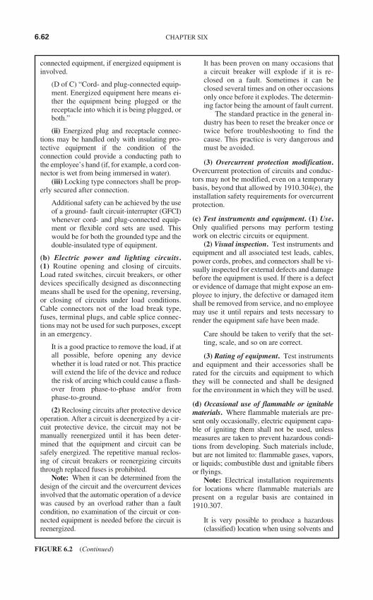
connected equipment, if energized equipment isinvolved.
(D of C) “Cord- and plug-connected equip-ment. Energized equipment here means ei-ther the equipment being plugged or thereceptacle into which it is being plugged, orboth.”
(ii) Energized plug and receptacle connec-tions may be handled only with insulating pro-tective equipment if the condition of theconnection could provide a conducting path tothe employee’s hand (if, for example, a cord con-nector is wet from being immersed in water).
(iii) Locking type connectors shall be prop-erly secured after connection.
Additional safety can be achieved by the useof a ground- fault circuit-interrupter (GFCI)whenever cord- and plug-connected equip-ment or flexible cord sets are used. Thiswould be for both the grounded type and thedouble-insulated type of equipment.
(b) Electric power and lighting circuits.(1) Routine opening and closing of circuits.Load rated switches, circuit breakers, or otherdevices specifically designed as disconnectingmeans shall be used for the opening, reversing,or closing of circuits under load conditions.Cable connectors not of the load break type,fuses, terminal plugs, and cable splice connec-tions may not be used for such purposes, exceptin an emergency.
It is a good practice to remove the load, if atall possible, before opening any devicewhether it is load rated or not. This practicewill extend the life of the device and reducethe risk of arcing which could cause a flash-over from phase-to-phase and/or fromphase-to-ground.
(2) Reclosing circuits after protective deviceoperation. After a circuit is deenergized by a cir-cuit protective device, the circuit may not bemanually reenergized until it has been deter-mined that the equipment and circuit can besafely energized. The repetitive manual reclos-ing of circuit breakers or reenergizing circuitsthrough replaced fuses is prohibited.
Note: When it can be determined from thedesign of the circuit and the overcurrent devicesinvolved that the automatic operation of a devicewas caused by an overload rather than a faultcondition, no examination of the circuit or con-nected equipment is needed before the circuit isreenergized.
It has been proven on many occasions thata circuit breaker will explode if it is re-closed on a fault. Sometimes it can beclosed several times and on other occasionsonly once before it explodes. The determin-ing factor being the amount of fault current.
The standard practice in the general in-dustry has been to reset the breaker once ortwice before troubleshooting to find thecause. This practice is very dangerous andmust be avoided.
(3) Overcurrent protection modification.Overcurrent protection of circuits and conduc-tors may not be modified, even on a temporarybasis, beyond that allowed by 1910.304(e), theinstallation safety requirements for overcurrentprotection.
(c) Test instruments and equipment. (1) Use.Only qualified persons may perform testingwork on electric circuits or equipment.
(2) Visual inspection. Test instruments andequipment and all associated test leads, cables,power cords, probes, and connectors shall be vi-sually inspected for external defects and damagebefore the equipment is used. If there is a defector evidence of damage that might expose an em-ployee to injury, the defective or damaged itemshall be removed from service, and no employeemay use it until repairs and tests necessary torender the equipment safe have been made.
Care should be taken to verify that the set-ting, scale, and so on are correct.
(3) Rating of equipment. Test instrumentsand equipment and their accessories shall berated for the circuits and equipment to whichthey will be connected and shall be designedfor the environment in which they will be used.
(d) Occasional use of flammable or ignitablematerials. Where flammable materials are pre-sent only occasionally, electric equipment capa-ble of igniting them shall not be used, unlessmeasures are taken to prevent hazardous condi-tions from developing. Such materials include,but are not limited to: flammable gases, vapors,or liquids; combustible dust and ignitable fibersor flyings.
Note: Electrical installation requirementsfor locations where flammable materials arepresent on a regular basis are contained in1910.307.
It is very possible to produce a hazardous(classified) location when using solvents and
6.62 CHAPTER SIX
FIGURE 6.2 (Continued)
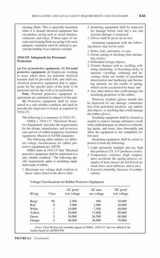
cleaning fluids. This is especially hazardouswhen it is around electrical equipment thatcan produce arcing such as circuit breakers,contactors, and relays. If these types of sol-vents and cleaning fluids are going to be used,adequate ventilation must be utilized to pre-vent the buildup of an explosive mixture.
1910.335 Safeguards for Personnel Protection
(a) Use of protective equipment. (1) Personalprotective equipment. (i) Employees workingin areas where there are potential electricalhazards shall be provided with, and shall use,electrical protective equipment that is appro-priate for the specific parts of the body to beprotected and for the work to be performed.
Note: Personal protective equipment re-quirements are contained in subpart I of this part.
(ii) Protective equipment shall be main-tained in a safe reliable condition and shall beperiodically inspected or tested, as required by1910.137.
The following is a summary of 1910.137:OSHA’s 1910.137 “Electrical Protec-
tive Equipment” provides the requirementsfor the design, manufacture, and in-servicecare and use of rubber temporary insulationequipment. (Based on ASTM standards)
The following table outlines six differ-ent voltage classifications for rubber pro-tective equipment per ASTM.
OSHA states in 1910.137 that “Electricalprotective equipment shall be maintained in asafe, reliable condition.” The following spe-cific requirements apply to insulating equip-ment made of rubber:
1. Maximum use voltage shall conform tothose values listed in the above table.
2. Insulating equipment shall be inspectedfor damage before each day’s use andanytime damage is suspected.
3. Gloves shall be given an air test.
Insulating equipment with the follow-ing defects may not be used:
1. Holes, tears, punctures, or cuts;2. Ozone cutting or checking (fine interlac-
ing cracks);3. Embedded foreign objects;4. Texture changes such as: swelling, soft-
ening, hardening, or becoming sticky orinelastic (swelling, softening and be-coming sticky are results of petroleumdeterioration and hardening and becom-ing inelastic are the results of ageing,which can be accelerated by heat); and
5. Any other defects that could damage theinsulating properties of the rubber.
Protector (leather) gloves should alsobe inspected for any damage, contamina-tion from petroleum products, any imbed-ded objects, or anything that could damagethe rubber gloves.
Insulating equipment shall be cleaned asneeded to remove foreign substances (washwith a mild detergent, no abrasives or bleach-ing agents, and water, rinse thoroughly andallow the equipment to dry completely be-fore use).
Insulating equipment shall be stored toprotect it from the following:
1. Light (primarily sunlight and any lightthat produces UV; UV produces ozone);
2. Temperature extremes (high tempera-tures accelerate the ageing process; ex-amples of heat sources are hot forced air,steam lines, near radiators, and so on.);
3. Excessive humidity (because of conden-sation);
REGULATORY AND LEGAL SAFETY REQUIREMENTS AND STANDARDS 6.63
FIGURE 6.2 (Continued)
Voltage Classifications for Rubber Protective Equipment
AC proof AC max. DC proof ID tag Class test voltage use voltage test voltage
Beige 00 2,500 500 10,000Red 0 5,000 1,000 20,000White 1 10,000 7,500 40,000Yellow 2 20,000 17,000 50,000Green 3 30,000 26,500 60,000Orange 4 40,000 36,000 70,000
Notes: Class 00 does not currently appear in OSHA, 1910.137, but was added by theAuthor based on ASTM F496
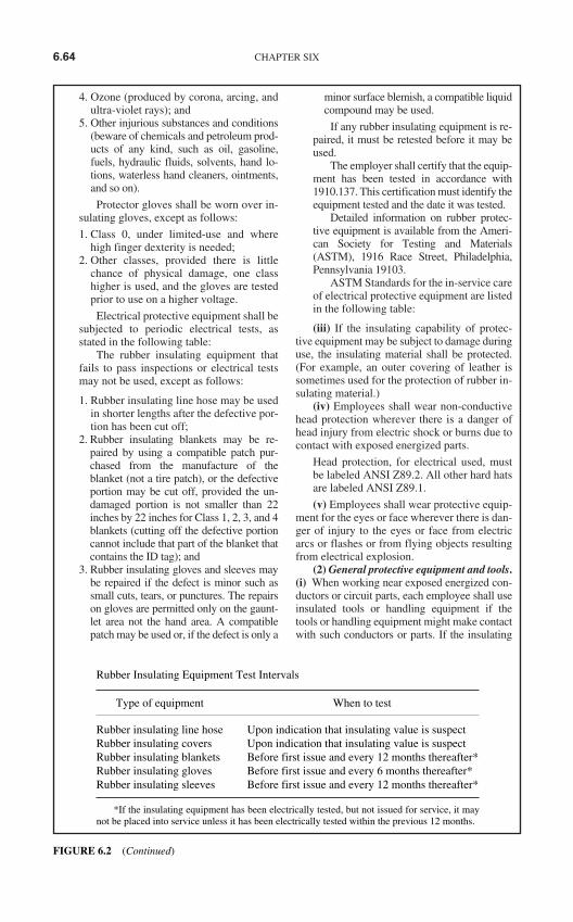
4. Ozone (produced by corona, arcing, andultra-violet rays); and
5. Other injurious substances and conditions(beware of chemicals and petroleum prod-ucts of any kind, such as oil, gasoline,fuels, hydraulic fluids, solvents, hand lo-tions, waterless hand cleaners, ointments,and so on).
Protector gloves shall be worn over in-sulating gloves, except as follows:
1. Class 0, under limited-use and wherehigh finger dexterity is needed;
2. Other classes, provided there is littlechance of physical damage, one classhigher is used, and the gloves are testedprior to use on a higher voltage.
Electrical protective equipment shall besubjected to periodic electrical tests, asstated in the following table:
The rubber insulating equipment thatfails to pass inspections or electrical testsmay not be used, except as follows:
1. Rubber insulating line hose may be usedin shorter lengths after the defective por-tion has been cut off;
2. Rubber insulating blankets may be re-paired by using a compatible patch pur-chased from the manufacture of theblanket (not a tire patch), or the defectiveportion may be cut off, provided the un-damaged portion is not smaller than 22inches by 22 inches for Class 1, 2, 3, and 4blankets (cutting off the defective portioncannot include that part of the blanket thatcontains the ID tag); and
3. Rubber insulating gloves and sleeves maybe repaired if the defect is minor such assmall cuts, tears, or punctures. The repairson gloves are permitted only on the gaunt-let area not the hand area. A compatiblepatch may be used or, if the defect is only a
minor surface blemish, a compatible liquidcompound may be used.
If any rubber insulating equipment is re-paired, it must be retested before it may beused.
The employer shall certify that the equip-ment has been tested in accordance with1910.137. This certification must identify theequipment tested and the date it was tested.
Detailed information on rubber protec-tive equipment is available from the Ameri-can Society for Testing and Materials(ASTM), 1916 Race Street, Philadelphia,Pennsylvania 19103.
ASTM Standards for the in-service careof electrical protective equipment are listedin the following table:
(iii) If the insulating capability of protec-tive equipment may be subject to damage duringuse, the insulating material shall be protected.(For example, an outer covering of leather issometimes used for the protection of rubber in-sulating material.)
(iv) Employees shall wear non-conductivehead protection wherever there is a danger ofhead injury from electric shock or burns due tocontact with exposed energized parts.
Head protection, for electrical used, mustbe labeled ANSI Z89.2. All other hard hatsare labeled ANSI Z89.1.
(v) Employees shall wear protective equip-ment for the eyes or face wherever there is dan-ger of injury to the eyes or face from electricarcs or flashes or from flying objects resultingfrom electrical explosion.
(2) General protective equipment and tools.(i) When working near exposed energized con-ductors or circuit parts, each employee shall useinsulated tools or handling equipment if thetools or handling equipment might make contactwith such conductors or parts. If the insulating
6.64 CHAPTER SIX
Rubber Insulating Equipment Test Intervals
Type of equipment When to test
Rubber insulating line hose Upon indication that insulating value is suspectRubber insulating covers Upon indication that insulating value is suspectRubber insulating blankets Before first issue and every 12 months thereafter*Rubber insulating gloves Before first issue and every 6 months thereafter*Rubber insulating sleeves Before first issue and every 12 months thereafter*
*If the insulating equipment has been electrically tested, but not issued for service, it maynot be placed into service unless it has been electrically tested within the previous 12 months.
FIGURE 6.2 (Continued)
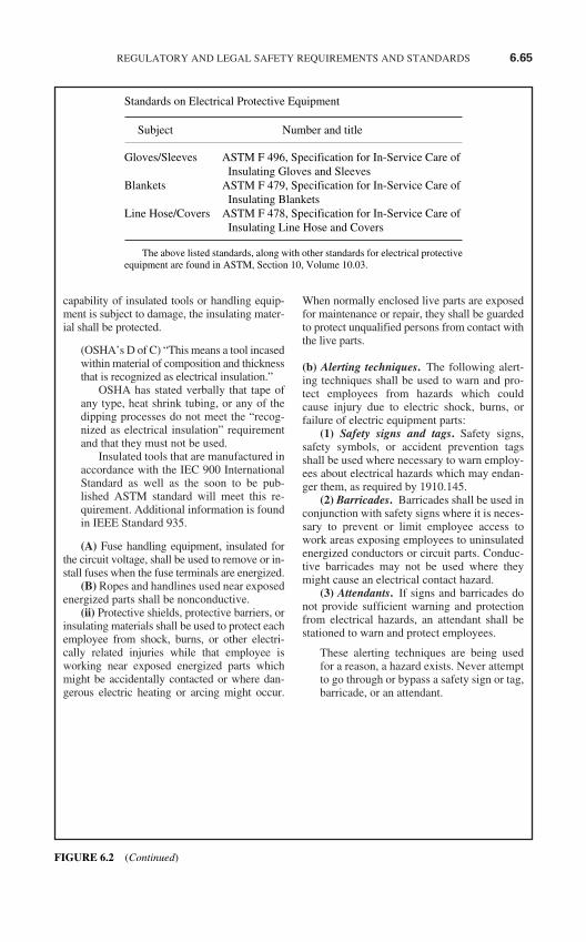
capability of insulated tools or handling equip-ment is subject to damage, the insulating mater-ial shall be protected.
(OSHA’s D of C) “This means a tool incasedwithin material of composition and thicknessthat is recognized as electrical insulation.”
OSHA has stated verbally that tape ofany type, heat shrink tubing, or any of thedipping processes do not meet the “recog-nized as electrical insulation” requirementand that they must not be used.
Insulated tools that are manufactured inaccordance with the IEC 900 InternationalStandard as well as the soon to be pub-lished ASTM standard will meet this re-quirement. Additional information is foundin IEEE Standard 935.
(A) Fuse handling equipment, insulated forthe circuit voltage, shall be used to remove or in-stall fuses when the fuse terminals are energized.
(B) Ropes and handlines used near exposedenergized parts shall be nonconductive.
(ii) Protective shields, protective barriers, orinsulating materials shall be used to protect eachemployee from shock, burns, or other electri-cally related injuries while that employee isworking near exposed energized parts whichmight be accidentally contacted or where dan-gerous electric heating or arcing might occur.
When normally enclosed live parts are exposedfor maintenance or repair, they shall be guardedto protect unqualified persons from contact withthe live parts.
(b) Alerting techniques. The following alert-ing techniques shall be used to warn and pro-tect employees from hazards which couldcause injury due to electric shock, burns, orfailure of electric equipment parts:
(1) Safety signs and tags. Safety signs,safety symbols, or accident prevention tagsshall be used where necessary to warn employ-ees about electrical hazards which may endan-ger them, as required by 1910.145.
(2) Barricades. Barricades shall be used inconjunction with safety signs where it is neces-sary to prevent or limit employee access towork areas exposing employees to uninsulatedenergized conductors or circuit parts. Conduc-tive barricades may not be used where theymight cause an electrical contact hazard.
(3) Attendants. If signs and barricades donot provide sufficient warning and protectionfrom electrical hazards, an attendant shall bestationed to warn and protect employees.
These alerting techniques are being usedfor a reason, a hazard exists. Never attemptto go through or bypass a safety sign or tag,barricade, or an attendant.
REGULATORY AND LEGAL SAFETY REQUIREMENTS AND STANDARDS 6.65
Standards on Electrical Protective Equipment
Subject Number and title
Gloves/Sleeves ASTM F 496, Specification for In-Service Care of Insulating Gloves and Sleeves
Blankets ASTM F 479, Specification for In-Service Care of Insulating Blankets
Line Hose/Covers ASTM F 478, Specification for In-Service Care of Insulating Line Hose and Covers
The above listed standards, along with other standards for electrical protectiveequipment are found in ASTM, Section 10, Volume 10.03.
FIGURE 6.2 (Continued)
ELECTRIC POWER GENERATION,TRANSMISSION, AND DISTRIBUTION
(OSHA 29 CFR 1910.269)(FINAL RULE JANUARY 31, 1994)
1910.269 Electric power generation, trans-mission, and distribution
1910.269 contains requirements for the pre-vention of injuries to employees performingoperation or maintenance work on electricpower generation, transmission, or distribu-tion installations.
The standard consists largely of workpractice requirements that are necessary foremployee safety. The Agency believes thatit is important to apply these work practicesin full to existing installations, as well as toconductors and equipment that are installedin the future.
The Agency has determined that employ-ees are presently facing significant risk. Therisk that an electric utility employee will be se-riously injured or die from a fall or an electricshock is significant. OSHA has determinedthat risk can be reduced by adopting a stan-dard that requires the industry to change exist-ing protective measures in certain cases. Theareas for which this holds true are explained inthe discussion of individual provisions.
(a) General. (1) Application. (i) This sectioncovers the operation and maintenance of elec-tric power generation, control, transformation,transmission, and distribution lines and equip-ment. These provisions apply to:
Paragraph (a)(1) sets forth the scope of thestandard. Under the terms of paragraph(a)(1)(i), the provisions of 1910.269 apply tothe operation and maintenance of electricpower generation, transmission, and distribu-tion systems, to electrical testing of such sys-tems, and to line-clearance tree trimming.
The standard primarily covers the fol-lowing types of work operations:
(1) Inspection,(2) Switching (connection and disconnec-
tion of facilities),(3) Maintenance of lines and equipment,(4) Line-clearance tree trimming,(5) Testing and fault locating,(6) Streetlight relamping,
(7) Chemical cleaning of boilers, and(8) Other operation and maintenance
activities.
According to proposed 1910.269(a)(1)(ii)(B), OSHA would only have applied theregulation to installations for the generation,transmission, or distribution of electric en-ergy that are owned or operated by electricutilities and to work performed on such in-stallations owned by a utility. Many industrialgeneration, transmission, and distribution sys-tems are essentially the same as those of autility, and the work performed on these sys-tems is nearly identical to that performed onelectric utility installations. Existing OSHAand national consensus standards, Subpart Vof Part 1926 and ANSI C2, respectively, doextend their coverage to anyone doing elec-tric-utility-type work.
OSHA received many comments onthis issue, from utilities, from electricalcontractors, from other industries, and fromunions. In general, the utilities supportedextending coverage to all generation, trans-mission, and distribution installations. Forexample, the New York State Electric andGas Corporation stated that their personnelperform work on transmission and distribu-tion interconnect facilities as well as in-spect, oversee, and approve protection systemdesign, installation, testing, and maintenanceon non-utility protection systems. Theiremployees also provide assistance toindustrial customers under emergencyconditions.
Unions also supported extending thescope of 1910.269. The International Broth-erhood of Electrical Workers (IBEW) statedthat the hazards, training, and work practicesare the same for electric power generation,transmission, and distribution facilities re-gardless of who owns or operates them.Therefore, they argued, the safety and healthrequirements should be the same.
The National Electrical Contractors As-sociation (NECA) represents the contractorswho perform work on utility and on indus-trial power generation, transmission, and dis-tribution installations. NECA agreed withIBEW that these installations were the same,no matter who owned or operated them, andthat the accident prevention measures shouldbe the same.
6.66 CHAPTER SIX
FIGURE 6.3 Electrical Power Generation, Transmission, and Distribution Rule (OSHA-CFR, Title 29,Part 1910, Paragraph 269).
Note: Reading the following paragraphs isa must in order to fully understand the ap-plication of 1910.269.
The installation safety requirements inSubpart S of Part 1910 (1910.302 through1910.308) do not cover “installations underthe exclusive control of electric utilities forthe generation, control, transformation, trans-mission, and distribution of electric energy”(1910.302(a)(2)(v)). Additionally, OSHA hasinterpreted the Subpart S installation require-ments to exempt industrial power generationand distribution systems that are similar toelectric utility installations. This exclusion re-flects the unique hazards and work practicesinvolved in generation, transmission, and dis-tribution of electric energy. The work practicerequirements in Subpart S of Part 1910(1910.332 through 1910.335) are designed tocomplement the installation safety provisionsin Subpart S and do not cover work practicesfor qualified persons who work on or nearelectric generation, transmission, or distribu-tion installations. Also, because electric powergeneration, transmission, and distribution in-stallations involve similar hazards and workpractices whether or not they are controlled byelectric utilities, the Subpart S work prac-tices standard does not apply to qualifiedpersons who work on or near any such in-stallation, regardless of who owns or con-trols the installation.
OSHA believes that there are hazards re-lated to electric power generation, transmis-sion, and distribution work that are notadequately addressed elsewhere in the Gen-eral Industry Standards. The hazards relatedto transmission systems are the samewhether the system is owned by a steel plant,a chemical plant, or an electric utility. Thereare currently no OSHA standards governingthe design or installation of these systems,and the electrical standards in Subpart S ofPart 1910 do not apply.
Coverage of electric power generationand distribution systems is slightly differentfrom the coverage of transmission systems.Utility-type generation and distribution in-stallations are not covered by the provisionsof 1910.303 through 1910.308 or (if thework is performed by a qualified employee)by 1910.332 through 1910.335. Commer-cial-type systems, however, are covered bythe Subpart S requirements. Additionally,some employers voluntarily comply withOSHA’s electrical standards in Subpart S for
their large-scale generation and distributioninstallations.
From an electrical viewpoint, thehazards faced by employees workingon an installation that conforms to thedesign requirements of 1910.303 through1910.308 are different from those faced byemployees working on an installation thatwas designed to conform to the NationalElectrical Safety Code. OSHA believes thatwhether an employer should comply withthe Subpart S work practice requirementsor with the provisions of 1910.269 dependson the hazards faced by an employee. Thehazards posed by an installation are relatedto the type of installation involved and towhether or not it conforms to the designstandards in Subpart S. The risk faced by anemployee working on the installation de-pends on what the hazards are and onwhether or not the employee is trained torecognize and avoid the hazards. Therefore,the Agency has made application of most ofthe electrical requirements in the new stan-dard dependent on whether or not the in-stallation conforms to 1910.303 through1910.308 and on whether or not the em-ployee is qualified to perform the work, noton whether or not the work is performed byan employee of an electric utility.
OSHA has determined which provi-sions of final 1910.269 address electricalhazards that are already addressed in1910.332 through 1910.335 of Subpart Sfor electrical installations that meet the de-sign requirements in 1910.302 through1910.308 of Subpart S. In short, when qual-ified employees work on such installations,the Agency will consider these installationsand work practices conforming to 1910.332through 1910.335 to be in compliance withthe provisions of 1910.269 that are identi-fied in of Appendix A-2.
OSHA has also identified requirementsin 1910.269 that are not adequately ad-dressed in Subpart S, and these requirementsmust be followed at all times. These provi-sions are listed in of Appendix A-2 as well.It should be noted that, if unqualified em-ployees are working on, near, or with elec-tric power generation, transmission, anddistribution installations, 1910.332 through1910.335 apply in any event. Appendices A-1 and A-2 illustrate the application of1910.269 and Subpart S to the various typesof electrical installations.
REGULATORY AND LEGAL SAFETY REQUIREMENTS AND STANDARDS 6.67
FIGURE 6.3 (Continued)
The non-electrical provisions in 1910.269(for example, paragraph (g)(2) on fall protec-tion and paragraph (p)(1) on mechanicalequipment) address only unique aspects ofelectric power generation, transmission, anddistribution work. As noted in paragraph(a)(1)(iii), the requirements of 1910.269 sup-plement those elsewhere in Part 1910, unlessan exception is specifically mentioned. Thenon-electrical requirements in this sectionhave been handled individually throughoutthe standard to allow alternative methods ofcompliance already recognized in the GeneralIndustry Standards. For example, the lockoutand tagging provisions of paragraph (d) rec-ognize compliance with the generic standardon control of hazardous energy sources in1910.147.
(A) Power generation, transmission, anddistribution installations, including relatedequipment for the purpose of communicationor metering, which are accessible only to qual-ified employees;
Note: The types of installations covered bythis paragraph include the generation, trans-mission, and distribution installations of elec-tric utilities, as well as equivalent installationsof industrial establishments. Supplementaryelectric generating equipment that is used tosupply a workplace for emergency, standby, orsimilar purposes only is covered under SubpartS of this Part. (See paragraph (a)(1)(ii)(B) ofthis section.)
Paragraph (a)(1)(i)(A) sets forth the scopeof 1910.269 as it relates to industrial andutility power generation, transmission, anddistribution.
OSHA believes that this language willeffectively extend the scope of the standardto the types of installations that the standardis intended to cover, namely, electric powergeneration, transmission, and distributionsystems of electric utilities and equivalentindustrial systems. It also makes it clear thatsupplementary generating equipment, suchas emergency and standby generators usedto provide temporary power at a workplace,is not covered. These installations are con-sidered to be part of the utilization systemrather than separate generation installationsand are addressed by the existing SubpartS regulations.
Section 1910.269 applies to the parts ofa facility that are directly involved with thegeneration, transmission, or distribution of
electric power. Installations not used for oneof these purposes are not covered by thestandard. For example, office buildings,warehouses, machine shops, and other in-stallations which are not integral parts ofgenerating plants, substations, or controlcenters are not covered by final 1910.269.Work performed on these installations is notof a type addressed by the standard.
(B) Other installations at an electric powergenerating station, as follows:
(1) Fuel and ash handling and processinginstallations, such as coal conveyors,
(2) Water and steam installations, such aspenstocks, pipelines, and tanks providing asource of energy for electric generators, and
(3) Chlorine and hydrogen systems;(C) Test sites where electrical testing in-
volving temporary measurements associatedwith electric power generation, transmission,and distribution is performed in laboratories, inthe field, in substations, and on lines, as op-posed to metering, relaying, and routine linework;
(D) Work on or directly associated with theinstallations covered in paragraphs (a)(1)(i)(A)through (a)(1)(i)(C) of this section; and
(E) Line-clearance tree-trimming opera-tions, as follows:
(1) Entire 1910.269 of this Part, except para-graph (r)(1), applies to line-clearance tree-trimming operations performed by qualifiedemployees (those who are knowledgeable in theconstruction and operation of electric power gen-eration, transmission, or distribution equipmentinvolved, along with the associated hazards).
(2) Paragraphs (a)(2), (b), (c), (g), (k), (p),and (r) of this section apply to line-clearancetree-trimming operations performed by line-clearance tree trimmers who are not qualifiedemployees.
Standards on the construction of transmissionand distribution lines and equipment are con-tained in 29 CFR Part 1926, Subpart V. So asnot to overlap these regulations in the Con-struction Standards, final 1910.269 publishedtoday does not apply to operations involvingconstruction work. This “exemption” is setforth in 1910.269(a)(1)(ii)(A). “Constructionwork” is defined in 1910.12(b) as “work forconstruction, alteration, and/or repair, includ-ing painting and decorating.” In 1910.12(d),the term is further defined as including “theerection of new electric transmission anddistribution lines and equipment, and the
6.68 CHAPTER SIX
FIGURE 6.3 (Continued)
alteration, conversion, and improvement ofexisting transmission and distribution linesand equipment.” None of the types of workcovered by these two definitions are coveredby 1910.269.
OSHA believes that it is important foremployees to use consistent work practicesfor jobs posing equivalent hazards. It may,indeed, introduce dangers if an employeehas to vary the work practices used for a jobdepending on slightly different circum-stances unrelated to safety. The Agency at-tempts to make its standards consistentacross industries for similar situations, but itis not always possible to make them identi-cal. The employer should ensure that thework rules are the same for similar jobs eventhough different regulations may apply.
(ii) Notwithstanding paragraph (a)(1)(i) ofthis section, 1910.269 of this Part does notapply:
(A) to construction work, as defined in1910.12 of this Part; or
(B) to electrical installations, electricalsafety-related work practices, or electricalmaintenance considerations covered by Sub-part S of this Part.
Note 1: Work practices conforming to1910.332 through 1910.335 of this Part areconsidered as complying with the electricalsafety-related work practice requirements ofthis section identified in Table 1 of AppendixA-2 to this section, provided the work is beingperformed on a generation or distribution in-stallation meeting 1910.303 through 1910.308of this Part. This table also identifies provi-sions in this section that apply to work by qual-ified persons directly on or associated withinstallations of electric power generation,transmission, and distribution lines or equip-ment, regardless of compliance with 1910.332through 1910.335 of this Part.
Note 2: Work practices performed by qual-ified persons and conforming to 1910.269 ofthis Part are considered as complying with1910.333(c) and 1910.335 of this Part.
The distinction, made under the scope ofPart I of Subpart S, between installationsused and those not used for the generationof electric power at utility plants is one thatcan be readily determined. OSHA realizesthat all circuits for utilization equipment in-stalled in generating stations must originatein the same area as the circuits for the gener-ating installation. However, at some point,
circuits that are not an integral part of thegenerating installation must become inde-pendent of the generating circuits, except tothe extent that they may share commoncable trays or perhaps raceways. Otherwise,it would be impossible to control the light-ing, for example, independently of the gen-erator itself. With respect to the existingrequirements of Part I of Subpart S, OSHAconsiders the “covered” installation tobegin where it becomes electrically inde-pendent of conductors and equipment usedfor the generation of electric power. In mostcases, it is a simple matter of tracing thewiring back from the utilization equipmentitself until a point is reached where genera-tion circuits are also supplied. Generally,branch circuits supplying utilization equip-ment (other than that used for the generationprocess) are covered; feeders supplyingonly “utilization” branch circuits are covered;feeders supplying “generation” circuits, aloneor in combination with “utilization” circuitsare not covered by Subpart S.
Electric utilization circuits in generatingplants do pose unique hazards if the circuitsare commingled with installations of powergeneration equipment or circuits and if thecommingled generation equipment or cir-cuits present greater electrical hazards thanthose posed by the utilization equipment orcircuits alone (such as exposure to highervoltages or lack of overcurrent protection).Under this condition, the work practices to beused would have to conform to 1910.269rather than 1910.332 through 1910.335, andthe Subpart S work practices standard doesnot apply.
(iii) This section applies in addition to allother applicable standards contained in thisPart 1910. Specific references in this section toother sections of Part 1910 are provided foremphasis only.
All other General Industry Standards con-tinue to apply to installations covered bythis new standard unless an exception isgiven in 1910.269.
(2) Training. (i) Employees shall betrained in and familiar with the safety-relatedwork practices, safety procedures, and othersafety requirements in this section that pertainto their respective job assignments. Employeesshall also be trained in and familiar with anyother safety practices, including applicableemergency procedures (such as pole top and
REGULATORY AND LEGAL SAFETY REQUIREMENTS AND STANDARDS 6.69
FIGURE 6.3 (Continued)
manhole rescue), that are not specifically ad-dressed by this section but that are related totheir work and are necessary for their safety.
The standard cannot specify requirements forevery hazard the employee faces in perform-ing electric power generation, transmission,or distribution work. Employers must fill inthis gap by training their employees in haz-ards that are anticipated during the course ofjobs they are expected to perform. This lan-guage clearly imparts OSHA’s intent thatsafety training be provided in areas that arenot covered by the standard but that are re-lated to the employee’s job.
(ii) Qualified employees shall also betrained and competent in:
Because qualified employees are allowedto work very close to electric power linesand equipment and because they face ahigh risk of electrocution, it is importantthat they be specially trained.
OSHA believes that qualified employ-ees need to be extensively trained in orderto perform their work safely.
(A) The skills and techniques necessary todistinguish exposed live parts from other partsof electric equipment,
(B) The skills and techniques necessary todetermine the nominal voltage of exposed liveparts,
(C) The minimum approach distancesspecified in this section corresponding to thevoltages to which the qualified employee willbe exposed, and
(D) The proper use of the special precau-tionary techniques, personal protective equip-ment, insulating and shielding materials, andinsulated tools for working on or near exposedenergized parts of electric equipment.
Note: For the purposes of this section, aperson must have this training in order to beconsidered a qualified person.
Paragraphs (a)(2)(i) and (a)(2)(ii) requireemployees to be trained. They do notspecifically require employers to providethis training themselves or to repeat trainingalready provided. Clearly, the plain lan-guage of the standard allows employees tobe trained by other parties or to have beentrained previously by their own employers.
(iii) The employer shall determine, throughregular supervision and through inspections
conducted on at least an annual basis that eachemployee is complying with the safety-relatedwork practices required by this section.
(iv) An employee shall receive additionaltraining (or retraining) under any of the follow-ing conditions:
(A) If the supervision and annual inspec-tions required by paragraph (a)(2)(iii) of thissection indicate that the employee is not com-plying with the safety-related work practicesrequired by this section, or
(B) If new technology, new types of equip-ment, or changes in procedures necessitate theuse of safety-related work practices that are dif-ferent from those which the employee wouldnormally use, or
(C) If he or she must employ safety-relatedwork practices that are not normally used dur-ing his or her regular job duties.
Note: OSHA would consider tasks that areperformed less often than once per year to ne-cessitate retraining before the performance ofthe work practices involved.
The note indicates that the Agency considerstasks performed less often than once peryear to require retraining before the task isactually performed. OSHA will accept in-struction provided in pre-job briefings if it isdetailed enough to fully inform the em-ployee of the procedures involved in the joband to ensure that he or she can accomplishthem in a safe manner. OSHA believes thatthis requirement will significantly improvesafety for electric power generation, trans-mission, and distribution workers.
(v) The training required by paragraph(a)(2) of this section shall be of the classroomor on-the-job type.
This paragraph permits classroom or on-the-job training or a combination of both. This al-lows employers to continue the types oftraining programs that are currently in exis-tence. Additionally, if an employee has al-ready been trained (through previous jobassignments, for example), the employer doesnot have to duplicate previous instruction.
(vi) The training shall establish employeeproficiency in the work practices required bythis section and shall introduce the proceduresnecessary for compliance with this section.
(vii) The employer shall certify that each em-ployee has received the training required byparagraph (a)(2) of this section. This certification
6.70 CHAPTER SIX
FIGURE 6.3 (Continued)
shall be made when the employee demonstratesproficiency in the work practices involved andshall be maintained for the duration of the em-ployee’s employment.
Note: Employment records that indicatethat an employee has received the requiredtraining are an acceptable means of meetingthis requirement.
The employer is required, by paragraph(a)(2)(vii), to certify that each employee hasbeen trained. This certification should not ne-cessitate the employer’s completing forms orcreating new records; existing personnelrecords would normally suffice or the em-ployer could simply make out a certificationfor each employee upon completion of train-ing. Employers relying on training providedby previous employers are expected to takesteps to verify that the employee has indeedreceived it.
OSHA has determined that there is aneed for employees to be trained on a con-tinuing basis. Initial instruction in safe tech-niques for performing specific job tasks isnot sufficient to ensure that employees willuse safe work practices all the time.
Continual reinforcement of this initialguidance must be provided to ensure that theemployee actually uses the procedures he orshe has been taught. This reinforcement cantake the form of supervision, safety meet-ings, pre-job briefings or conferences, andretraining. Typically, adequate supervisioncan detect unsafe work practices with respectto tasks that are routine and are performed ona daily or regular basis. However, if an em-ployee has to use a technique that is appliedinfrequently or that is based on new technol-ogy, some follow-up is needed to ensure thatthe employee is actually aware of the correctprocedure for accomplishing the task. A de-tailed job briefing, as required under1910.269(c)(2), may be adequate if the em-ployee has previously received some instruc-tion, but training would be necessary if theemployee has never been schooled in thetechniques to be used.
While there is substantial evidence in therecord that electric utility employees arehighly skilled and well trained, OSHA isconcerned that a few employers may inaccu-rately “certify” the training of some employ-ees who have not demonstrated proficiencyin the work practices required by the stan-dard. An example will help to illustrate the
need for the standard to address the overallgoals of the training program. A complextagging program and extensive training forthat program, is characterized as typical forthe electric utility industry as a whole. Withrespect to training in tagging procedures:
These detailed procedures, together withthe safety manual, serve a dual purpose. Theyestablish the specific requirements and pro-vide the explicit direction for protection ofemployees from hazardous energy and theycomprise the text material which is the basisfor employee training in protection from haz-ardous energy. The training process is rigor-ous, including classroom presentation byqualified instructors, as well as self-study andit does include testing. Employees mustdemonstrate knowledge and skill in the appli-cation of hazardous energy control, consistentwith established acceptance criteria, beforethey are qualified to either request that equip-ment be removed from service and tagged out,or to execute switching, valving, and tagging.
An employee who has attended a singletraining class on a procedure that is as com-plex as the lockout and tagging procedureused in an electric generating plant has gen-erally not been fully trained in that proce-dure. Unless a training program establishesan employee’s proficiency in safe work prac-tices and that employee then demonstrateshis or her ability to perform those work prac-tices, there will be no assurance that safework practices will result, and overall em-ployee safety will not benefit nearly as muchas it could.
Compliance with paragraph (a)(2)(vii)will ensure that employers do not try to com-ply with 1910.269 by simply handing trainingmanuals to their employees. These provisionswill require employers to take steps to assurethat employees comprehend what they havebeen taught and that they are capable of per-forming the work practices mandated by thestandard. OSHA believes that these two para-graphs will maximize the benefits of thetraining required under the standard.
OSHA believes that the training require-ments contained in the final standard are suf-ficient to protect employees performingelectric power generation, transmission, anddistribution work. However, in every indus-try, there will be some employers who arenot as faithful in following safety and healthstandards as others. The Agency intends tovigorously enforce the training requirements
REGULATORY AND LEGAL SAFETY REQUIREMENTS AND STANDARDS 6.71
FIGURE 6.3 (Continued)
of the final rule, because much of the work-er’s safety depends on knowledge of andskills in proper working procedures. Thecombination of rigorous training provisionswith strict enforcement of these rules will re-sult in increased safety to employees.
(3) Existing conditions. Existing condi-tions related to the safety of the work to be per-formed shall be determined before work on ornear electric lines or equipment is started. Suchconditions include, but are not limited to, thenominal voltages of lines and equipment, themaximum switching transient voltages, thepresence of hazardous induced voltages, thepresence and condition of protective groundsand equipment grounding conductors, the con-dition of poles, environmental conditions rela-tive to safety, and the locations of circuits andequipment, including power and communica-tion lines and fire protective signaling circuits.
This paragraph relates to hazards commonto all types of electrical work, not just over-head line work. For example, the conditionof the equipment grounding conductor thatmay be provided on a motor that is part of agenerating installation affects the safety ofanyone working on that motor.
(b) Medical services and first aid. The em-ployer shall provide medical services and firstaid as required in 1910.151 of this Part. In ad-dition to the requirements of 1910.151 of thisPart, the following requirements also apply:
The introductory text of paragraph (b) em-phasizes that the requirements of 1910.151apply. That existing section includes provi-sions for available medical personnel, firstaid training and supplies, and facilities fordrenching or flushing of the eyes and body inthe event of exposure to corrosive materials.
Because of the hazard of electric shockwhen employees are performing work on orwith energized lines and equipment, electricpower generation, transmission, and distrib-ution workers suffer electrocution on thejob. Cardiopulmonary resuscitation (CPR) isnecessary in the event of electric shock sothat injured employees can be revived. CPRmust be started within 4 minutes to be effec-tive in reviving an employee whose hearthas gone into fibrillation.
(1) Cardiopulmonary resuscitation andfirst aid training. When employees are per-forming work on or associated with exposedlines or equipment energized at 50 volts or
more, persons trained in first aid including car-diopulmonary resuscitation (CPR) shall beavailable as follows:
(i) For field work involving two or moreemployees at a work location, at least twotrained persons shall be available. However,only one trained person need be available if allnew employees are trained in first aid, includ-ing CPR, within 3 months of their hiring dates.
(ii) For fixed work locations such as gener-ating stations, the number of trained personsavailable shall be sufficient to ensure that eachemployee exposed to electric shock can bereached within 4 minutes by a trained person.However, where the existing number of em-ployees is insufficient to meet this requirement(at a remote substation, for example), all em-ployees at the work location shall be trained.
Mr. Robert Felix of the National ArboristAssociation (NAA) argued that CPR was ofdubious value with respect to injuries causedby electric shock. In NAA’s post-hearingbrief, he stated: “a study of the precise issueby medical experts (Cardiologist F. Gravino,M.D., F.A.C.C., et al.) commissioned byNAA and submitted to the Record as part ofNAA’s post-hearing evidence submission tothe Docket, along with other related Recordevidence, demonstrates the following med-ical assessment:
1. There is no demonstrated value of CPRin the electric injury context.
2. CPR is of no value to a person exposedto high voltage shock because of atten-dant “irreversible damage of either theautonomic nervous system or the cardiactissue itself.”
3. Lower voltage contacts from indirect con-tacts do “not respond to CPR”—see Na-tional Safety Council Newsletter ofJuly/August 1990, at p. 1, submitted to theDocket by NAA as part of its post-hearingevidence submission. Moreover, suchlower voltage contacts may induce respi-ratory block, rather than cardiac block, asto which artificial respiration, which istaught to line clearance tree trimmers aspart of first-aid training, provides appro-priate assistance, for which CPR wouldprovide no additional benefit—a pointconceded by NIOSH.
4. Even if otherwise appropriate in an elec-trical context—a fact not supported by theevidence—CPR is of value only if fol-lowed by defibrillation within 8 minutesof the onset of ventricular fibrillation.
6.72 CHAPTER SIX
FIGURE 6.3 (Continued)
The likelihood of getting an 8 minute ambu-lance response time to a line clearance jobsite is remote. . . . The dubious value of CPRfurther is attenuated by the remote likeli-hood of obtaining the required defibrillationwithin 8 minutes.
Others asserted that CPR was usefuland necessary for the protection of workersexposed to electric shock. Dr. RichardNiemeier of NIOSH stated that currentmedical guidelines recommend CPR treat-ment, as follows:
The revised “Standards and Guidelinesfor Cardiopulmonary Resuscitation (CPR)and Emergency Cardiac Care (ECC)” rec-ommend the same treatment for cardiopul-monary arrest, whether spontaneous orassociated with electrical shock. The guide-lines noted the complications of electricshock that might require CPR includingtetany of the muscles used for breathing dur-ing contact with the electrical current, pro-longed paralysis of breathing muscles for aperiod following the electric contact, andcardiac arrest. This discussion considers twocategories: (1) respiratory arrest (with pulse)and (2) cardiac arrest.
NIOSH reviewed studies on the effec-tiveness of CPR in resuscitating electricshock victims. Regarding this review of theavailable evidence, Mr. Niemeier stated:
The question posed by OSHA, at thistime, however, is whether sufficient evi-dence exists to support the recommendationthat utility linemen work in pairs and betrained in CPR. Medical ethics and commonsense prohibit a prospective study with ran-dom allocation of electrical shock or othercardiac arrest victims to “CPR” and “non-CPR” groups. This question must be an-swered, therefore, by clinical epidemiologicstudies that are less than perfect. Cumminsand Eisenberg[1985] reviewed the evidenceregarding the relationship of early CPR andsurvival following cardiac arrest. The au-thors found nine studies that they consideredcredible (before 1985); all nine studies re-ported that early CPR had a beneficial effect.Cummins and Eisenberg[1985] concludedthat the evidence clearly supported the con-cept that early CPR (begun on the scene bylay persons) leads to better survival ratesthan CPR delayed until emergency medicalpersonnel arrive. These studies generally ex-clude trauma victims from analysis; this factdoes not preclude the extrapolation of these
results to patients with cardiac rhythm dis-turbances secondary to contact with electri-cal energy.
(2) First aid supplies. First aid supplies re-quired by 1910.151(b) of this Part shall beplaced in weatherproof containers if the sup-plies could be exposed to the weather.
(3) First aid kits. Each first aid kit shall bemaintained, shall be readily available for use,and shall be inspected frequently enough to en-sure that expended items are replaced at leastonce per year.
(c) Job briefing. The employer shall ensurethat the employee in charge conducts a jobbriefing with the employees involved beforethey start each job. The briefing shall cover atleast the following subjects: hazards associatedwith the job, work procedures involved, specialprecautions, energy source controls, and per-sonal protective equipment requirements.
Most of the work performed under the stan-dard requires planning in order to ensureemployee safety (as well as to protectequipment and the general public).
If the work is not thoroughly plannedahead of time, the possibility of human erroris increased greatly. To avoid problems, thetask sequence is prescribed before work isstarted. For example, before climbing a pole,the employee must determine if the pole iscapable of remaining in place and if mini-mum approach distances are sufficient, andhe or she must determine what tools will beneeded and what procedure should be usedfor performing the job. Without job plan-ning, the worker may ignore the minimumapproach distance requirements or may haveto reclimb the pole to retrieve a forgotten toolor perform an overlooked task, resulting inincreased exposure to the hazards of fallingand contact with energized lines.
When more than one employee is in-volved, the job plan must be communicatedto all the affected employees. If the job isplanned but the plan is not discussed with theworkers, one employee may perform his orher duties out of order or may otherwise notcoordinate activities with the rest of the crew,endangering the entire crew. Therefore,OSHA is requiring a job briefing before workis started. The briefing would cover: hazardsand work procedures involved, special pre-cautions, energy source controls, and require-ments for personal protective equipment.
REGULATORY AND LEGAL SAFETY REQUIREMENTS AND STANDARDS 6.73
FIGURE 6.3 (Continued)
(1) Number of briefings. If the work or op-erations to be performed during the work day orshift are repetitive and similar, at least one jobbriefing shall be conducted before the start of thefirst job of each day or shift. Additional job brief-ings shall be held if significant changes, whichmight affect the safety of the employees, occurduring the course of the work.
At least one briefing is required to be con-ducted before the start of each shift. Only onebriefing in a shift is needed if all the jobs aresimilar in nature. Additional planning discus-sions must take place for work involving sig-nificant changes in routine. For example, ifthe first two jobs of the day involve workingon a de-energized line and the third job in-volves working on energized lines withlive-line tools, separate briefings must beconducted for each type of job.
(2) Extent of briefing. A brief discussion issatisfactory if the work involved is routine and ifthe employee, by virtue of training and experi-ence, can reasonably be expected to recognizeand avoid the hazards involved in the job. Amore extensive discussion shall be conducted:
(i) If the work is complicated or particu-larly hazardous, or
(ii) If the employee cannot be expected torecognize and avoid the hazards involved in thejob.
Note: The briefing is always required totouch on all the subjects listed in the introduc-tory text to paragraph (c) of this section.
The required briefing would normally con-sist of a concise discussion outlining thetasks to be performed. However, if thework is particularly hazardous or if the em-ployees may not be able to recognize thehazards involved, then a more thoroughdiscussion must take place. With this provi-sion, OSHA recognizes that employees arefamiliar with the tasks and hazards in-volved with routine work. However, it isimportant to take the time to carefully dis-cuss unusual work situations that may poseadditional or different hazards to workers.
(3) Working alone. An employee workingalone need not conduct a job briefing. How-ever, the employer shall ensure that the tasks tobe performed are planned as if a briefing wererequired.
(d) Hazardous energy control (lockout/tagout) procedures. (1) Application. The provi-sions of paragraph (d) of this section apply to theuse of lockout/tagout procedures for the control
of energy sources in installations for the purposeof electric power generation, including relatedequipment for communication or metering.Locking and tagging procedures for the de-ener-gizing of electric energy sources which are usedexclusively for purposes of transmission and dis-tribution are addressed by paragraph (m) of thissection.
Note 1: Installations in electric power gen-eration facilities that are not an integral part of,or inextricably commingled with, power gener-ation processes or equipment are covered under1910.147 and Subpart S of this Part.
Note 2: Lockout and tagging proceduresthat comply with paragraphs (c) through (f) of1910.147 of this Part will also be deemed tocomply with paragraph (d) of this section if theprocedures address the hazards covered byparagraph (d) of this section.
(2) General. (i) The employer shall estab-lish a program consisting of energy controlprocedures, employee training, and periodic in-spections to ensure that, before any employeeperforms any servicing or maintenance on amachine or equipment where the unexpectedenergizing, start up, or release of stored energycould occur and cause injury, the machine orequipment is isolated from the energy sourceand rendered inoperative.
(ii) The employer’s energy control programunder paragraph (d)(2) of this section shallmeet the following requirements:
(A) If an energy isolating device is not ca-pable of being locked out, the employer’s pro-gram shall use a tagout system.
(B) If an energy isolating device is capableof being locked out, the employer’s programshall use lockout, unless the employer candemonstrate that the use of a tagout system willprovide full employee protection as follows:
(1) When a tagout device is used on an en-ergy isolating device which is capable of beinglocked out, the tagout device shall be attachedat the same location that the lockout devicewould have been attached, and the employershall demonstrate that the tagout program willprovide a level of safety equivalent to that ob-tained by the use of a lockout program.
(2) In demonstrating that a level of safety isachieved in the tagout program equivalent to thelevel of safety obtained by the use of a lockoutprogram, the employer shall demonstrate fullcompliance with all tagout-related provisions ofthis standard together with such additional ele-ments as are necessary to provide the equivalentsafety available from the use of a lockout device.Additional means to be considered as part of the
6.74 CHAPTER SIX
FIGURE 6.3 (Continued)
demonstration of full employee protection shallinclude the implementation of additional safetymeasures such as the removal of an isolating cir-cuit element, blocking of a controlling switch,opening of an extra disconnecting device, or theremoval of a valve handle to reduce the likeli-hood of inadvertent energizing.
(C) After November 1, 1994, whenever re-placement or major repair, renovation, or modifi-cation of a machine or equipment is performed,and whenever new machines or equipment areinstalled, energy isolating devices for such ma-chines or equipment shall be designed to accepta lockout device.
(iii) Procedures shall be developed, docu-mented, and used for the control of potentiallyhazardous energy covered by paragraph (d) ofthis section.
(iv) The procedure shall clearly and specif-ically outline the scope, purpose, responsibil-ity, authorization, rules, and techniques to beapplied to the control of hazardous energy, andthe measures to enforce compliance including,but not limited to, the following:
(A) A specific statement of the intendeduse of this procedure;
(B) Specific procedural steps for shuttingdown, isolating, blocking and securing machinesor equipment to control hazardous energy;
(C) Specific procedural steps for the place-ment, removal, and transfer of lockout devicesor tagout devices and the responsibility forthem; and
(D) Specific requirements for testing a ma-chine or equipment to determine and verify theeffectiveness of lockout devices, tagout de-vices, and other energy control measures.
(v) The employer shall conduct a periodicinspection of the energy control procedure atleast annually to ensure that the procedure andthe provisions of paragraph (d) of this sectionare being followed.
(A) The periodic inspection shall be per-formed by an authorized employee who isnot using the energy control procedure beinginspected.
(B) The periodic inspection shall be de-signed to identify and correct any deviations orinadequacies.
(C) If lockout is used for energy control, theperiodic inspection shall include a review be-tween the inspector and each authorized em-ployee, of that employee’s responsibilities underthe energy control procedure being inspected.
(D) Where tagout is used for energy con-trol, the periodic inspection shall include a
review between the inspector and each au-thorized and affected employee, of that em-ployee’s responsibilities under the energycontrol procedure being inspected, and theelements set forth in paragraph (d)(2)(vii) ofthis section.
(E) The employer shall certify that the in-spections required by paragraph (d)(2)(v) ofthis section have been accomplished. The certi-fication shall identify the machine or equip-ment on which the energy control procedurewas being used, the date of the inspection, theemployees included in the inspection, and theperson performing the inspection.
Note: If normal work schedule and opera-tion records demonstrate adequate inspectionactivity and contain the required information,no additional certification is required.
(vi) The employer shall provide training toensure that the purpose and function of the en-ergy control program are understood by employ-ees and that the knowledge and skills requiredfor the safe application, usage, and removal ofenergy controls are acquired by employees. Thetraining shall include the following:
(A) Each authorized employee shall re-ceive training in the recognition of applicablehazardous energy sources, the type and magni-tude of energy available in the workplace, andin the methods and means necessary for energyisolation and control.
(B) Each affected employee shall be in-structed in the purpose and use of the energycontrol procedure.
(C) All other employees whose work opera-tions are or may be in an area where energy con-trol procedures may be used shall be instructedabout the procedures and about the prohibitionrelating to attempts to restart or reenergize ma-chines or equipment that are locked out ortagged out.
(vii) When tagout systems are used, em-ployees shall also be trained in the followinglimitations of tags:
(A) Tags are essentially warning devicesaffixed to energy isolating devices and do notprovide the physical restraint on those devicesthat is provided by a lock.
(B) When a tag is attached to an energy iso-lating means, it is not to be removed withoutauthorization of the authorized person respon-sible for it, and it is never to be bypassed, ig-nored, or otherwise defeated.
(C) Tags must be legible and understand-able by all authorized employees, affected em-ployees, and all other employees whose work
REGULATORY AND LEGAL SAFETY REQUIREMENTS AND STANDARDS 6.75
FIGURE 6.3 (Continued)
operations are or may be in the area, in order tobe effective.
(D) Tags and their means of attachmentmust be made of materials which will withstandthe environmental conditions encountered inthe workplace.
(E) Tags may evoke a false sense of secu-rity, and their meaning needs to be understoodas part of the overall energy control program.
(F) Tags must be securely attached to en-ergy isolating devices so that they cannot be in-advertently or accidentally detached during use.
(viii) Retraining shall be provided by theemployer as follows:
(A) Retraining shall be provided for all au-thorized and affected employees whenever thereis a change in their job assignments, a change inmachines, equipment, or processes that present anew hazard or whenever there is a change in theenergy control procedures.
(B) Retraining shall also be conductedwhenever a periodic inspection under para-graph (d)(2)(v) of this section reveals, or when-ever the employer has reason to believe, thatthere are deviations from or inadequacies in anemployee’s knowledge or use of the energycontrol procedures.
(C) The retraining shall reestablish employeeproficiency and shall introduce new or revisedcontrol methods and procedures, as necessary.
(ix) The employer shall certify that employeetraining has been accomplished and is being keptup to date. The certification shall contain eachemployee’s name and dates of training.
(3) Protective materials and hardware.(i) Locks, tags, chains, wedges, key blocks,adapter pins, self-locking fasteners, or otherhardware shall be provided by the employer forisolating, securing, or blocking of machines orequipment from energy sources.
(ii) Lockout devices and tagout devicesshall be singularly identified; shall be the onlydevices used for controlling energy; may not beused for other purposes; and shall meet the fol-lowing requirements:
(A) Lockout devices and tagout devicesshall be capable of withstanding the environ-ment to which they are exposed for the maxi-mum period of time that exposure is expected.
(1) Tagout devices shall be constructed andprinted so that exposure to weather conditionsor wet and damp locations will not cause thetag to deteriorate or the message on the tag tobecome illegible.
(2) Tagout devices shall be so constructedas not to deteriorate when used in corrosive en-vironments.
(B) Lockout devices and tagout devicesshall be standardized within the facility in atleast one of the following criteria: color, shape,and size. Additionally, in the case of tagout de-vices, print and format shall be standardized.
(C) Lockout devices shall be substantialenough to prevent removal without the use of ex-cessive force or unusual techniques, such as withthe use of bolt cutters or metal cutting tools.
(D) Tagout devices, including their means ofattachment, shall be substantial enough to pre-vent inadvertent or accidental removal. Tagoutdevice attachment means shall be of a non-reusable type, attachable by hand, self-locking,and non-releasable with a minimum unlockingstrength of no less than 50 pounds and shall havethe general design and basic characteristics ofbeing at least equivalent to a one-piece, all-envi-ronment-tolerant nylon cable tie.
(E) Each lockout device or tagout deviceshall include provisions for the identification ofthe employee applying the device.
(F) Tagout devices shall warn against haz-ardous conditions if the machine or equipmentis energized and shall include a legend such asthe following: Do Not Start, Do Not Open, DoNot Close, Do Not Energize, Do Not Operate.
Note: For specific provisions covering acci-dent prevention tags, see 1910.145 of this Part.
(4) Energy isolation. Lockout and tagoutdevice application and removal may only beperformed by the authorized employees whoare performing the servicing or maintenance.
(5) Notification. Affected employees shallbe notified by the employer or authorized em-ployee of the application and removal of lockoutor tagout devices. Notification shall be given be-fore the controls are applied and after they are re-moved from the machine or equipment.
Note: See also paragraph (d)(7) of this sec-tion, which requires that the second notificationtake place before the machine or equipment isreenergized.
(6) Lockout/tagout application. The es-tablished procedures for the application of en-ergy control (the lockout or tagout procedures)shall include the following elements and ac-tions, and these procedures shall be performedin the following sequence:
(i) Before an authorized or affected em-ployee turns off a machine or equipment, theauthorized employee shall have knowledge ofthe type and magnitude of the energy, the haz-ards of the energy to be controlled, and themethod or means to control the energy.
(ii) The machine or equipment shall beturned off or shut down using the procedures
6.76 CHAPTER SIX
FIGURE 6.3 (Continued)
established for the machine or equipment. Anorderly shutdown shall be used to avoid anyadditional or increased hazards to employees asa result of the equipment stoppage.
(iii) All energy isolating devices that areneeded to control the energy to the machine orequipment shall be physically located and op-erated in such a manner as to isolate the ma-chine or equipment from energy sources.
(iv) Lockout or tagout devices shall be af-fixed to each energy isolating device by autho-rized employees.
(A) Lockout devices shall be attached in amanner that will hold the energy isolating de-vices in a “safe” or “off” position.
(B) Tagout devices shall be affixed in sucha manner as will clearly indicate that the oper-ation or movement of energy isolating devicesfrom the “safe” or “off” position is prohibited.
(1) Where tagout devices are used with en-ergy isolating devices designed with the capa-bility of being locked out, the tag attachmentshall be fastened at the same point at which thelock would have been attached.
(2) Where a tag cannot be affixed directlyto the energy isolating device, the tag shall belocated as close as safely possible to the device,in a position that will be immediately obviousto anyone attempting to operate the device.
(v) Following the application of lockout ortagout devices to energy isolating devices, allpotentially hazardous stored or residual energyshall be relieved, disconnected, restrained, orotherwise rendered safe.
(vi) If there is a possibility of reaccumulationof stored energy to a hazardous level, verificationof isolation shall be continued until the servicingor maintenance is completed or until the possibil-ity of such accumulation no longer exists.
(vii) Before starting work on machines orequipment that have been locked out or taggedout, the authorized employee shall verify thatisolation and deenergizing of the machine orequipment have been accomplished. If normallyenergized parts will be exposed to contact by anemployee while the machine or equipment isdeenergized, a test shall be performed to ensurethat these parts are deenergized.
(7) Release from lockout/tagout. Beforelockout or tagout devices are removed and en-ergy is restored to the machine or equipment,procedures shall be followed and actionstaken by the authorized employees to ensurethe following:
(i) The work area shall be inspected to en-sure that nonessential items have been removed
and that machine or equipment components areoperationally intact.
(ii) The work area shall be checked to en-sure that all employees have been safely posi-tioned or removed.
(iii) After lockout or tagout devices havebeen removed and before a machine or equip-ment is started, affected employees shall be no-tified that the lockout or tagout devices havebeen removed.
(iv) Each lockout or tagout device shall be re-moved from each energy isolating device by theauthorized employee who applied the lockout ortagout device. However, if that employee is notavailable to remove it, the device may be re-moved under the direction of the employer, pro-vided that specific procedures and training forsuch removal have been developed, documented,and incorporated into the employer’s energy con-trol program. The employer shall demonstratethat the specific procedure provides a degree ofsafety equivalent to that provided by the removalof the device by the authorized employee who ap-plied it. The specific procedure shall include atleast the following elements:
(A) Verification by the employer that theauthorized employee who applied the device isnot at the facility;
(B) Making all reasonable efforts to contactthe authorized employee to inform him or herthat his or her lockout or tagout device has beenremoved; and
(C) Ensuring that the authorized employeehas this knowledge before he or she resumeswork at that facility.
(8) Additional requirements. (i) If thelockout or tagout devices must be temporarilyremoved from energy isolating devices and themachine or equipment must be energized to testor position the machine, equipment, or compo-nent thereof, the following sequence of actionsshall be followed:
(A) Clear the machine or equipment oftools and materials in accordance with para-graph (d)(7)(i) of this section;
(B) Remove employees from the machineor equipment area in accordance with para-graphs (d)(7)(ii) and (d)(7)(iii) of this section;
(C) Remove the lockout or tagout devices asspecified in paragraph (d)(7)(iv) of this section;
(D) Energize and proceed with the testingor positioning; and
(E) Deenergize all systems and reapply en-ergy control measures in accordance with para-graph (d)(6) of this section to continue theservicing or maintenance.
REGULATORY AND LEGAL SAFETY REQUIREMENTS AND STANDARDS 6.77
FIGURE 6.3 (Continued)
(ii) When servicing or maintenance is per-formed by a crew, craft, department, or othergroup, they shall use a procedure which affordsthe employees a level of protection equivalent tothat provided by the implementation of a per-sonal lockout or tagout device. Group lockout ortagout devices shall be used in accordance withthe procedures required by paragraphs (d)(2)(iii)and (d)(2)(iv) of this section including, but notlimited to, the following specific requirements:
(A) Primary responsibility shall be vestedin an authorized employee for a set number ofemployees working under the protection of agroup lockout or tagout device (such as an op-erations lock);
(B) Provision shall be made for the autho-rized employee to ascertain the exposure status ofall individual group members with regard to thelockout or tagout of the machine or equipment;
(C) When more than one crew, craft, depart-ment, or other group is involved, assignment ofoverall job-associated lockout or tagout controlresponsibility shall be given to an authorized em-ployee designated to coordinate affected workforces and ensure continuity of protection; and
(D) Each authorized employee shall affix apersonal lockout or tagout device to the grouplockout device, group lockbox, or comparablemechanism when he or she begins work andshall remove those devices when he or shestops working on the machine or equipmentbeing serviced or maintained.
(iii) Procedures shall be used during shift orpersonnel changes to ensure the continuity oflockout or tagout protection, including provisionfor the orderly transfer of lockout or tagout de-vice protection between off-going and on-com-ing employees, to minimize their exposure tohazards from the unexpected energizing or start-up of the machine or equipment or from the re-lease of stored energy.
(iv) Whenever outside servicing personnelare to be engaged in activities covered by para-graph (d) of this section, the on-site employerand the outside employer shall inform eachother of their respective lockout or tagout pro-cedures, and each employer shall ensure thathis or her personnel understand and complywith restrictions and prohibitions of the energycontrol procedures being used.
(v) If energy isolating devices are installedin a central location and are under the exclusivecontrol of a system operator, the following re-quirements apply:
(A) The employer shall use a procedurethat affords employees a level of protection
equivalent to that provided by the implementa-tion of a personal lockout or tagout device.
(B) The system operator shall place and re-move lockout and tagout devices in place of theauthorized employee under paragraphs (d)(4),(d)(6)(iv), and (d)(7)(iv) of this section.
(C) Provisions shall be made to identify theauthorized employee who is responsible for(that is, being protected by) the lockout ortagout device, to transfer responsibility forlockout and tagout devices, and to ensure thatan authorized employee requesting removal ortransfer of a lockout or tagout device is the oneresponsible for it before the device is removedor transferred.
(e) Enclosed spaces. This paragraph covers en-closed spaces that may be entered by employ-ees. It does not apply to vented vaults if adetermination is made that the ventilation sys-tem is operating to protect employees beforethey enter the space. This paragraph applies toroutine entry into enclosed spaces in lieu of thepermit-space entry requirements contained inparagraphs (d) through (k) of 1910.146 of thisPart. If, after the precautions given in para-graphs (e) and (t) of this section are taken, thehazards remaining in the enclosed space endan-ger the life of an entrant or could interfere withescape from the space, then entry into the en-closed space shall meet the permit-space entryrequirements of paragraphs (d) through (k) of1910.146 of this Part.
An “enclosed space” is defined to be aspace that has a limited means of entry oregress, that is designed for periodic entryby employees under normal operating con-ditions, and that is not expected to contain ahazardous atmosphere, but may containone under unusual conditions. In this para-graph, OSHA intends to cover only thetypes of enclosed spaces that are routinelyentered by employees engaged in electricpower generation, transmission, and distri-bution work and are unique to undergroundutility work. Work in these spaces is part ofthe day-to-day activities performed by em-ployees protected by this standard. En-closed spaces include manholes and vaultsthat provide employees access to electricgeneration, transmission, and distributionequipment. This paragraph does not ad-dress other types of confined spaces, suchas boilers, tanks, and coal bunkers, that arecommon to other industries as well. These
6.78 CHAPTER SIX
FIGURE 6.3 (Continued)
locations are addressed in OSHA’s genericpermit-required confined space standard,1910.146, which applies to all of generalindustry, including industries engaged inelectric power generation, transmission,and distribution work.
Section 1910.146 contains requirementsthat address hazards associated with entryinto “permit-required confined spaces” (per-mit spaces). Section 1910.146 defines “con-fined space” and “permit-required confinedspace” as follows:
Confined space means a space that:
(1) is large enough and so configured thatan employee can bodily enter and per-form assigned work; and
(2) has limited or restricted means for entryor exit (for example, tanks, vessels,silos, storage bins, hoppers, vaults, andpits are spaces that may have limitedmeans of entry.); and
(3) is not designed for continuous em-ployee occupancy.
Permit-required confined space (permitspace) means a confined space that has oneor more of the following characteristics:
(1) Contains or has a potential to contain ahazardous atmosphere;
(2) Contains a material that has the poten-tial for engulfing an entrant;
(3) Has an internal configuration such thatan entrant could be trapped or asphyxi-ated by inwardly converging walls orby a floor which slopes downward andtapers to a smaller cross-section; or
(4) Contains any other recognized serioussafety or health hazard.
The permit-required confined spacesstandard requires employers to implementa comprehensive confined space entry pro-gram. This standard covers the wide rangeof permit-required confined spaces encoun-tered throughout general industry. Becausethe hazards posed by these spaces vary sogreatly, 1910.146 requires employers toimplement a permit system for entry intothem. The permit system must spell out thesteps to be taken to make the space safe forentry and must include provisions for atten-dants stationed outside the spaces and forrescue of entrants, who could be disabledinside the space. However, an employerneed not follow the permit-entry require-ments of 1910.146 for spaces where thehazards have been completely eliminated
or for spaces where an alternative set ofprocedures are observed. The alternativeprocedures apply only where the spacecan be made safe for entry through the useof continuous forced air ventilation alone.The procedures, which are set forth in1910.146(c)(5)(ii), ensure that conditionswithin the permit space do not endanger anentrant’s life or ability to rescue himself orherself.
Paragraph (e) of 1910.269 applies to “en-closed spaces”. By definition, an enclosedspace would be a permit-required confinedspace in the absence of 1910.269. An en-closed space meets the definition of a con-fined space—it is large enough for anemployee to enter; it has a limited means ofaccess or egress; it is designed for periodic,rather than continuous, employee occupancyunder normal operating conditions. An en-closed space also meets the definition of apermit space—although it is not expected tocontain a hazardous atmosphere, it has thepotential to contain one. The Agency notesthat, if hazardous conditions which cannot becontrolled through the precautions set out inparagraphs (e) and (t) of final 1910.269 arepresent, the enclosed space must be treated asa permit space under 1910.146.
Note: Entries into enclosed spaces con-ducted in accordance with the permit-spaceentry requirements of paragraphs (d) through(k) of 1910.146 of this Part are considered ascomplying with paragraph (e) of this section.
(1) Safe work practices. The employershall ensure the use of safe work practices forentry into and work in enclosed spaces and forrescue of employees from such spaces.
Paragraph (e)(1) sets forth the general re-quirement that employers ensure the use ofsafe work practices by their employees.These safe work practices must include pro-cedures for complying with the specific reg-ulations contained in paragraphs (e)(4)through (e)(14) and must include safe rescueprocedures.
(2) Training. Employees who enter en-closed spaces or who serve as attendants shallbe trained in the hazards of enclosed spaceentry, in enclosed space entry procedures, andin enclosed space rescue procedures.
(3) Rescue equipment. Employers shallprovide equipment to ensure the prompt and saferescue of employees from the enclosed space.
REGULATORY AND LEGAL SAFETY REQUIREMENTS AND STANDARDS 6.79
FIGURE 6.3 (Continued)
The equipment must enable a rescuer to re-move an injured employee from the enclosedspace quickly and without injury to the res-cuer or further harm to the fallen employee.A harness, a lifeline, and a self-supportingwinch can normally be used in this manner.
(4) Evaluation of potential hazards. Be-fore any entrance cover to an enclosed space isremoved, the employer shall determinewhether it is safe to do so by checking for thepresence of any atmospheric pressure or tem-perature differences and by evaluating whetherthere might be a hazardous atmosphere in thespace. Any conditions making it unsafe to re-move the cover shall be eliminated before thecover is removed.
Note: The evaluation called for in thisparagraph may take the form of a check of theconditions expected to be in the enclosedspace. For example, the cover could bechecked to see if it is hot and, if it is fastened inplace, could be loosened gradually to releaseany residual pressure. A determination mustalso be made of whether conditions at the sitecould cause a hazardous atmosphere, such asan oxygen deficient or flammable atmosphere,to develop within the space.
Some conditions within an enclosed space,such as high temperature and high pressure,make it hazardous to remove any coverfrom the space. For example, if high pres-sure is present within the space, the covercould be blown off in the process of remov-ing it. To protect employees from suchhazards, paragraph (e)(4) requires a deter-mination of whether or not it is safe to re-move the cover. This determination maytake the form of a quick check of the condi-tions expected to be in the enclosed space.For example, the cover could be checked tosee if it is hot and, if it is fastened in place,could be loosened gradually to release anyresidual pressure. An evaluation must alsobe made of whether conditions at the sitecould cause a hazardous atmosphere to ac-cumulate in the space. Any conditionsmaking it unsafe for employees to removethe cover are required to be eliminated (thatis, reduced to the extent that it is no longerunsafe).
(5) Removal of covers. When covers are re-moved from enclosed spaces, the opening shallbe promptly guarded by a railing, temporarycover, or other barrier intended to prevent anaccidental fall through the opening and to
protect employees working in the space fromobjects entering the space.
(6) Hazardous atmosphere. Employeesmay not enter any enclosed space while it con-tains a hazardous atmosphere, unless the entryconforms to the generic permit-required con-fined spaces standard in 1910.146 of this Part.
Note: The term “entry” is defined in1910.146(b) of this Part.
OSHA has noted earlier, paragraph (e) is in-tended to apply only to routine entry into en-closed spaces, where compliance with theprocedures set out in paragraphs (e) and (t)adequately protects employees. If a haz-ardous atmosphere exists in an enclosedspace after the testing and ventilation re-quirements in paragraphs (e)(9) through(e)(13) of 1910.269 have been met, addi-tional measures must be taken to protect em-ployees. When this is the case, the genericpermit-spaces standard in 1910.146 containsthe relevant requirements necessary to pro-tect entrants. Paragraph (e)(6) of 1910.269makes this clear. (It should be noted thatSubpart Z of Part 1910 continues to applyto the exposure of employees to toxicsubstances.)
(7) Attendants. While work is being per-formed in the enclosed space, a person withfirst aid training meeting paragraph (b) of thissection shall be immediately available outsidethe enclosed space to render emergency assis-tance if there is reason to believe that a hazardmay exist in the space or if a hazard exists be-cause of traffic patterns in the area of the open-ing used for entry. That person is not precludedfrom performing other duties outside the en-closed space if these duties do not distract theattendant from monitoring employees withinthe space.
Note: See paragraph (t)(3) of this sectionfor additional requirements on attendants forwork in manholes.
Paragraph (e)(7) addresses the use of an at-tendant outside the enclosed space to provideassistance in an emergency. An attendant isrequired if there is reason to believe that ahazard exists within the space or if a hazardexists because of traffic patterns near theopening. For example, a manhole containingenergized electric equipment that is in dangerof failing catastrophically requires an atten-dant under this paragraph. The purpose of theattendant would be to provide assistance inan emergency.
6.80 CHAPTER SIX
FIGURE 6.3 (Continued)
If this person were to enter the enclosedspace, he or she might be unable to assist theemployee already within the space. For ex-ample, if traffic hazards are present in thearea of the opening to the enclosed space andif the attendant entered the space, then boththe attendant and the workers he or she is in-tended to protect would be vulnerable uponleaving. No one would be present to mini-mize or control the traffic hazards. If flood-ing hazards are present, a person outside thespace may be able to assist in a rescue at-tempt; an attendant inside the space wouldlikely be another victim. Therefore, the finalrule explicitly states that the attendant is re-quired to remain outside the enclosed space.
On the other hand, if there is no reasonto believe that a hazard exists inside the en-closed space and if no traffic hazards arepresent, an attendant would still be requiredunder 1910.269(t)(3) while work is beingperformed in a manhole containing ener-gized conductors. The major, though notthe only, hazard in this case is that of elec-tric shock. Assistance can be provided to avictim of electric shock by another personin the manhole. Therefore, the provisionsof paragraph (t)(3) permit the attendant re-quired under that paragraph to enter themanhole for brief periods of time. How-ever, it should be noted that 1910.269(e)(7)requires the attendant to be “immediatelyavailable outside the space”. Thus, an at-tendant required by paragraph (e)(7) (ratherthan by paragraph (t)(3)) is required to re-main outside the space.
(8) Calibration of test instruments. Testinstruments used to monitor atmospheres in en-closed spaces shall be kept in calibration, witha minimum accuracy of ±10 percent.
(9) Testing for oxygen deficiency. Beforean employee enters an enclosed space, the in-ternal atmosphere shall be tested for oxygendeficiency with a direct-reading meter or simi-lar instrument, capable of collection and imme-diate analysis of data samples without the needfor off-site evaluation. If continuous forced airventilation is provided, testing is not requiredprovided that the procedures used ensure thatemployees are not exposed to the hazardsposed by oxygen deficiency.
(10) Testing for flammable gases and va-pors. Before an employee enters an enclosedspace, the internal atmosphere shall be tested forflammable gases and vapors with a direct-readingmeter or similar instrument capable of collection
and immediate analysis of data samples withoutthe need for off-site evaluation. This test shall beperformed after the oxygen testing and ventila-tion required by paragraph (e)(9) of this sectiondemonstrate that there is sufficient oxygen to en-sure the accuracy of the test for flammability.
(11) Ventilation and monitoring. If flam-mable gases or vapors are detected or if an oxy-gen deficiency is found, forced air ventilationshall be used to maintain oxygen at a safe leveland to prevent a hazardous concentration offlammable gases and vapors from accumulat-ing. A continuous monitoring program to en-sure that no increase in flammable gas or vaporconcentration occurs may be followed in lieuof ventilation, if flammable gases or vapors aredetected at safe levels.
Note: See the definition of hazardous at-mosphere for guidance in determining whetheror not a given concentration of a substance isconsidered to be hazardous.
(12) Specific ventilation requirements. Ifcontinuous forced air ventilation is used, it shallbegin before entry is made and shall be main-tained long enough to ensure that a safe atmos-phere exists before employees are allowed toenter the work area. The forced air ventilationshall be so directed as to ventilate the immedi-ate area where employees are present within theenclosed space and shall continue until all em-ployees leave the enclosed space.
(13) Air supply. The air supply for thecontinuous forced air ventilation shall be froma clean source and may not increase the haz-ards in the enclosed space.
(14) Open flames. If open flames are used inenclosed spaces, a test for flammable gases andvapors shall be made immediately before theopen flame device is used and at least once perhour while the device is used in the space. Test-ing shall be conducted more frequently if condi-tions present in the enclosed space indicate thatonce per hour is insufficient to detect hazardousaccumulations of flammable gases or vapors.
Note: See the definition of hazardous at-mosphere for guidance in determining whetheror not a given concentration of a substance isconsidered to be hazardous.
(f) Excavations. Excavation operations shallcomply with Subpart P of Part 1926 of thischapter.
(g) Personal protective equipment. (1) Gen-eral. Personal protective equipment shall meetthe requirements of Subpart I of this Part.
REGULATORY AND LEGAL SAFETY REQUIREMENTS AND STANDARDS 6.81
FIGURE 6.3 (Continued)
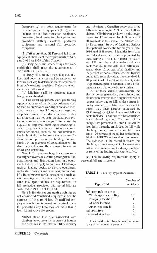
Paragraph (g) sets forth requirements forpersonal protective equipment (PPE), whichincludes eye and face protection, respiratoryprotection, head protection, foot protection,protective clothing, electrical protectiveequipment, and personal fall protectionequipment.
(2) Fall protection. (i) Personal fall arrestequipment shall meet the requirements of Sub-part E of Part 1926 of this Chapter.
(ii) Body belts and safety straps for workpositioning shall meet the requirements of1926.959 of this Chapter.
(iii) Body belts, safety straps, lanyards, life-lines, and body harnesses shall be inspected be-fore use each day to determine that the equipmentis in safe working condition. Defective equip-ment may not be used.
(iv) Lifelines shall be protected againstbeing cut or abraded.
(v) Fall arrest equipment, work positioningequipment, or travel restricting equipment shallbe used by employees working at elevated loca-tions more than 4 feet (1.2 m) above the groundon poles, towers, or similar structures if otherfall protection has not been provided. Fall pro-tection equipment is not required to be used bya qualified employee climbing or changing lo-cation on poles, towers, or similar structures,unless conditions, such as, but not limited to,ice, high winds, the design of the structure (forexample, no provision for holding on withhands), or the presence of contaminants on thestructure, could cause the employee to lose hisor her grip or footing.
Note 1: This paragraph applies to structuresthat support overhead electric power generation,transmission and distribution lines, and equip-ment. It does not apply to portions of buildings,such as loading docks, to electric equipment,such as transformers and capacitors, nor to aeriallifts. Requirements for fall protection associatedwith walking and working surfaces are con-tained in Subpart D of this Part; requirements forfall protection associated with aerial lifts arecontained in 1910.67 of this Part.
Note 2: Employees undergoing training arenot considered “qualified employees” for thepurposes of this provision. Unqualified em-ployees (including trainees) are required to usefall protection any time they are more than 4feet (1.2 m) above the ground.
NIOSH stated that risks associated withclimbing poles are a major cause of injuriesand fatalities in the electric utility industry
and submitted a Canadian study that listedfalls as accounting for 21.9 percent of all ac-cidents. “Climbing up or down a pole, tower,basket, truck” accounted for 14.8 percent ofall accidents in this study. The “IBEW Util-ity Department Survey of Fatal and SeriousOccupational Accidents” for the years 1984,1986, and 1988 report 13 fatalities from slipsand falls during the period represented bythese surveys. The total number of deathswas 121, and the total non-electrical acci-dents was 37. In this data base, falls repre-sented about 12 percent of all fatalities and35 percent of non-electrical deaths. Injuriesdue to falls from elevations were involved in10 percent (61 of 637) of the fatality/cata-strophe investigations recorded. These inves-tigations included only electric utilities.
All of these exhibits demonstrate thatelectric power generation, transmission, anddistribution workers face a significant risk ofserious injury due to falls under current in-dustry practices. To determine the extent towhich they face hazards addressed by1910.269(g)(2)(v), OSHA analyzed fall acci-dents included in various exhibits containedin the rulemaking record. The results of thisanalysis are presented in Table 1. As can beseen from the table, employees do fall whileclimbing poles, towers, or similar struc-tures—26 percent of the falling accidents re-lated to 1910.269 occurred in this manner.The evidence in the record indicates thatclimbing a pole, tower, or similar structure isnot as safe, under current industry practices,as some of the hearing witnesses testified.
(vi) The following requirements apply topersonal fall arrest systems:
6.82 CHAPTER SIX
FIGURE 6.3 (Continued)
TABLE 1 Falls by Type of Accident
Number ofType of fall accidents
Fall from pole or towerClimbing or descending 10Changing location 1At work location 7Other (not stated) 3
Fall from tree 6Failure of structure 12
Each accident involves the death or seriousinjury of one or more employees.
(A) When stopping or arresting a fall, per-sonal fall arrest systems shall limit the maxi-mum arresting force on an employee to 900pounds (4 kN) if used with a body belt.
(B) When stopping or arresting a fall, per-sonal fall arrest systems shall limit the maxi-mum arresting force on an employee to 1800pounds (8 kN) if used with a body harness.
(C) Personal fall arrest systems shall berigged such that an employee can neither free fallmore than 6 feet (1.8 m) nor contact any lowerlevel.
(vii) If vertical lifelines or droplines areused, not more than one employee may be at-tached to any one lifeline.
This limitation recognizes that it is inherentlyunsafe to use a single vertical lifeline to tie offtwo or more employees performing separatetasks. Movement by one employee couldcause the lifeline to be pulled to one side. Thiscould, in turn, cause the other employee tolose balance. Therefore, if one employee didfall, movement of the lifeline during the arrestof the fall would very likely cause other em-ployees connected to the lifeline to fall.
(viii) Snaphooks may not be connected toloops made in webbing-type lanyards.
(ix) Snaphooks may not be connected toeach other.
(h) Ladders, platforms, step bolts, and manholesteps (1) General. Requirements for ladderscontained in Subpart D of this Part apply, exceptas specifically noted in paragraph (h)(2) of thissection.
(2) Special ladders and platforms. Portableladders and platforms used on structures or con-ductors in conjunction with overhead line workneed not meet paragraphs (d)(2)(i) and(d)(2)(iii) of 1910.25 of this Part or paragraph(c)(3)(iii) of 1910.26 of this Part. However,these ladders and platforms shall meet the fol-lowing requirements:
(i) Ladders and platforms shall be securedto prevent their becoming accidentally dis-lodged.
(ii) Ladders and platforms may not beloaded in excess of the working loads forwhich they are designed.
(iii) Ladders and platforms may be used onlyin applications for which they were designed.
(iv) In the configurations in which they areused, ladders and platforms shall be capable ofsupporting without failure at least 2.5 times themaximum intended load.
(3) Conductive ladders. Portable metalladders and other portable conductive laddersmay not be used near exposed energized linesor equipment. However, in specialized high-voltage work, conductive ladders shall be usedwhere the employer can demonstrate that non-conductive ladders would present a greaterhazard than conductive ladders.
(i) Hand and portable power tools. (1) Gen-eral. Paragraph (i)(2) of this section applies toelectric equipment connected by cord and plug.Paragraph (i)(3) of this section applies toportable and vehicle-mounted generators usedto supply cord- and plug-connected equipment.Paragraph (i)(4) of this section applies to hy-draulic and pneumatic tools.
(2) Cord- and plug-connected equipment.(i) Cord-and plug-connected equipment sup-plied by premises wiring is covered by SubpartS of this Part.
(ii) Any cord- and plug-connected equip-ment supplied by other than premises wiringshall comply with one of the following in lieuof 1910.243(a)(5) of this Part:
(A) It shall be equipped with a cord contain-ing an equipment grounding conductor con-nected to the tool frame and to a means forgrounding the other end (however, this optionmay not be used where the introduction of theground into the work environment increases thehazard to an employee); or
(B) It shall be of the double-insulated typeconforming to Subpart S of this Part; or
(C) It shall be connected to the power sup-ply through an isolating transformer with anungrounded secondary.
If the equipment is supplied by the wiring ofa building or other premises, existing Sub-part S of Part 1910 continues to apply as itdoes now. If premises wiring is not involved(in which case Subpart S does not currentlyapply), paragraph (i)(2)(ii) requires that thetool frame be grounded or that the tool bedouble insulated or that the tool be suppliedby an isolating transformer with ungroundedsecondary. Any of these three methods canprotect employees from electric shock,which could directly injure the employee orwhich could cause an involuntary reactionleading to a secondary injury.
OSHA received several comments sug-gesting that ground-fault circuit interrupter(GFCI) protection be allowed as an addi-tional alternative. However, although a GFCIcan prevent electrocution, the device cannot
REGULATORY AND LEGAL SAFETY REQUIREMENTS AND STANDARDS 6.83
FIGURE 6.3 (Continued)
by itself prevent an initial electric shock to anemployee before it interrupts the circuit. Thisinitial shock could lead to injury from invol-untary reaction. This is of particular concernif the employee is in an elevated position, ex-posing him or her to a fall in the event ofelectric shock. For this reason, existing elec-trical standards require GFCI protection inaddition to, not in place of, equipmentgrounding and double insulation. Therefore,OSHA is not allowing the use of a GFCIalone to protect employees using cord- andplug-connected equipment.
(3) Portable and vehicle-mounted genera-tors. Portable and vehicle-mounted generatorsused to supply cord- and plug-connected equip-ment shall meet the following requirements:
(i) The generator may only supply equipmentlocated on the generator or the vehicle and cord-and plug-connected equipment through recepta-cles mounted on the generator or the vehicle.
(ii) The non-current-carrying metal parts ofequipment and the equipment grounding con-ductor terminals of the receptacles shall bebonded to the generator frame.
(iii) In the case of vehicle-mounted genera-tors, the frame of the generator shall be bondedto the vehicle frame.
(iv) Any neutral conductor shall be bondedto the generator frame.
(4) Hydraulic and pneumatic tools. (i) Safeoperating pressures for hydraulic and pneumatictools, hoses, valves, pipes, filters, and fittingsmay not be exceeded.
Note: If any hazardous defects are present,no operating pressure would be safe, and thehydraulic or pneumatic equipment involvedmay not be used. In the absence of defects, themaximum rated operating pressure is the maxi-mum safe pressure.
(ii) A hydraulic or pneumatic tool usedwhere it may contact exposed live parts shallbe designed and maintained for such use.
(iii) The hydraulic system supplying a hy-draulic tool used where it may contact exposedlive parts shall provide protection against lossof insulating value for the voltage involved dueto the formation of a partial vacuum in the hy-draulic line.
Note: Hydraulic lines without check valveshaving a separation of more than 35 feet (10.7m) between the oil reservoir and the upper endof the hydraulic system promote the formationof a partial vacuum.
(iv) A pneumatic tool used on energizedelectric lines or equipment or used where it may
contact exposed live parts shall provide protec-tion against the accumulation of moisture in theair supply.
(v) Pressure shall be released before connec-tions are broken, unless quick acting, self-closingconnectors are used. Hoses may not be kinked.
(vi) Employees may not use any part oftheir bodies to locate or attempt to stop a hy-draulic leak.
(j) Live-line tools. (1) Design of tools. Live-line tool rods, tubes, and poles shall be de-signed and constructed to withstand thefollowing minimum tests:
(i) 100,000 volts per foot (3281 volts percentimeter) of length for 5 minutes if the tool ismade of fiberglass-reinforced plastic (FRP), or
(ii) 75,000 volts per foot (2461 volts percentimeter) of length for 3 minutes if the tool ismade of wood, or
(iii) Other tests that the employer candemonstrate are equivalent.
Note: Live-line tools using rod and tubethat meet ASTM F711-89, Standard Specifica-tion for Fiberglass-Reinforced Plastic (FRP)Rod and Tube Used in Live-Line Tools, con-form to paragraph (j)(1)(i) of this section.
(2) Condition of tools. (i) Each live-linetool shall be wiped clean and visually inspectedfor defects before use each day.
(ii) If any defect or contamination thatcould adversely affect the insulating qualitiesor mechanical integrity of the live-line tool ispresent after wiping, the tool shall be removedfrom service and examined and tested accord-ing to paragraph (j)(2)(iii) of this section beforebeing returned to service.
(iii) Live-line tools used for primary em-ployee protection shall be removed from serviceevery 2 years and whenever required underparagraph (j)(2)(ii) of this section for examina-tion, cleaning, repair, and testing as follows:
(A) Each tool shall be thoroughly examinedfor defects.
(B) If a defect or contamination that couldadversely affect the insulating qualities or me-chanical integrity of the live-line tool is found,the tool shall be repaired and refinished or shallbe permanently removed from service. If nosuch defect or contamination is found, the toolshall be cleaned and waxed.
(C) The tool shall be tested in accordancewith paragraphs (j)(2)(iii)(D) and (j)(2)(iii)(E)of this section under the following conditions:
(1) After the tool has been repaired or re-finished; and
6.84 CHAPTER SIX
FIGURE 6.3 (Continued)
(2) After the examination if repair or refin-ishing is not performed, unless the tool is madeof FRP rod or foam-filled FRP tube and theemployer can demonstrate that the tool has nodefects that could cause it to fail in use.
(D) The test method used shall be designedto verify the tool’s integrity along its entireworking length and, if the tool is made of fiber-glass-reinforced plastic, its integrity under wetconditions.
(E) The voltage applied during the testsshall be as follows:
(1) 75,000 volts per foot (2461 volts percentimeter) of length for 1 minute if the tool ismade of fiberglass, or
(2) 50,000 volts per foot (1640 volts percentimeter) of length for 1 minute if the tool ismade of wood, or
(3) Other tests that the employer candemonstrate are equivalent.
Note: Guidelines for the examination,cleaning, repairing, and in-service testing oflive-line tools are contained in the Institute ofElectrical and Electronics Engineers Guide forIn-Service Maintenance and Electrical Testingof Live-Line Tools, IEEE Std. 978-1984.
(k) Materials handling and storage. (1) Gen-eral. Material handling and storage shall con-form to the requirements of Subpart N of thisPart.
(2) Materials storage near energized linesor equipment. (i) In areas not restricted to qual-ified persons only, materials or equipment maynot be stored closer to energized lines or ex-posed energized parts of equipment than thefollowing distances plus an amount providingfor the maximum sag and side swing of all con-ductors and providing for the height and move-ment of material handling equipment:
(A) For lines and equipment energized at50 kV or less, the distance is 10 feet (305 cm).
(B) For lines and equipment energized atmore than 50 kV, the distance is 10 feet (305cm) plus 4 inches (10 cm) for every 10 kV over50 kV.
(ii) In areas restricted to qualified employ-ees, material may not be stored within theworking space about energized lines or equip-ment.
Note: Requirements for the size of theworking space are contained in paragraphs(u)(1) and (v)(3) of this section.
Maintaining these clearances protects un-qualified employees, who are not trained in
the recognition and avoidance of the hazardsinvolved, from contacting the energized linesor equipment with materials being handled.However, the work practices these unquali-fied workers would employ in handling ma-terial stored near energized lines areaddressed by Subpart S. The general ap-proach taken in new 1910.269 is to providesafety-related work practices for qualifiedemployees to follow when they are perform-ing electric power generation, transmission,and distribution work. Safe work practicesfor unqualified employees are not addressedin final 1910.269, because these practices arealready spelled out in Subpart S of OSHA’sGeneral Industry Standards (see in particular1910.333(c)(3)(i) for work performed by un-qualified employees near overhead powerlines).
Paragraph (k)(2)(i) only regulates thestorage of materials where exposure is notrestricted to qualified employees. If the ma-terials are stored where only qualified work-ers have access to them, the materials maybe safely stored closer to the energized partsthan 10 feet, providing these employeeshave sufficient room to perform their work.
The working space about electric equip-ment is the clear space to be provided aroundthe equipment to enable qualified employeesto work on the equipment. An employee en-ters this space to service or maintain the elec-tric equipment. The minimum working spacespecifies the minimum distance an obstructioncan be from the equipment. For example, if aswitchboard is installed in a cabinet intowhich an employee will enter, the inside wallsof the cabinet must provide a minimum work-ing space to enable the employee to worksafely within the cabinet.
The minimum approach distance to bemaintained from a live part is the limit of thespace about the equipment that a qualifiedemployee is not permitted to enter. The min-imum approach distance a qualified em-ployee must maintain from an energized partare smaller than the working space that is re-quired to be provided around the part. Theemployee must “enter” the working spaceand still maintain the minimum approachdistance. Storing materials in this spacewould tempt employees to work on ener-gized equipment in cramped quarters if ac-cess were necessary in an emergency.Alternatively, if materials stored in the work-ing space had to be moved so that adequate
REGULATORY AND LEGAL SAFETY REQUIREMENTS AND STANDARDS 6.85
FIGURE 6.3 (Continued)
room could be provided, accidents could re-sult from the movement of the material.
(l) Working on or near exposed energizedparts. This paragraph applies to work on ex-posed live parts, or near enough to them, to ex-pose the employee to any hazard they present.
(1) General. Only qualified employees maywork on or with exposed energized lines or partsof equipment. Only qualified employees maywork in areas containing unguarded, uninsulatedenergized lines or parts of equipment operatingat 50 volts or more. Electric lines and equipmentshall be considered and treated as energized un-less the provisions of paragraph (d) or paragraph(m) of this section have been followed.
Paragraph (l)(1) requires employees work-ing on or in areas containing exposed liveparts of electric lines or equipment to bequalified. Without proper training in theconstruction and operation of the lines andequipment and in the electrical hazards in-volved, workers would likely be electro-cuted attempting to perform this type ofwork and would also expose others to in-jury as well. In areas containing unguardedlive parts energized at more than 50 volts,untrained employees would not be familiarwith the practices that are necessary to rec-ognize and avoid contact with these parts.
However, employees in training, underthe direct supervision of a qualified em-ployee, are permitted to perform work onlive parts and in areas containing unguardedlive parts. OSHA believes that the close su-pervision of trainees will reveal errors “in theact”, before they cause accidents. Allowingthese workers the experience of performingtasks under actual conditions may also betterprepare the employees to work safely.
The Agency has added a note to the de-finition of “qualified employee” to indicatethat employees who are undergoing on-the-job training are considered to be qualified ifthey have demonstrated an ability to per-form duties safely and if they are underthe immediate supervision of qualifiedemployees.
(i) Except as provided in paragraph(l)(1)(ii) of this section, at least two employeesshall be present while the following types ofwork are being performed:
(A) Installation, removal, or repair of linesthat are energized at more than 600 volts,
(B) Installation, removal, or repair of deener-gized lines if an employee is exposed to contactwith other parts energized at more than 600 volts,
(C) Installation, removal, or repair ofequipment, such as transformers, capacitors,and regulators, if an employee is exposed tocontact with parts energized at more than 600volts,
(D) Work involving the use of mechanicalequipment, other than insulated aerial lifts,near parts energized at more than 600 volts,and
(E) Other work that exposes an employeeto electrical hazards greater than or equal tothose posed by operations that are specificallylisted in paragraphs (l)(1)(i)(A) through(l)(1)(i)(D) of this section.
Many employer and employee groups com-mented on the issue of whether or not aminimum of two employees should be re-quired for work involving energized elec-tric equipment.
OSHA believes that the most relevantconsideration in determining whether ornot to require the presence of at least twoemployees is whether the hazards of thework would be significantly reduced bythe presence of an additional worker.Therefore, OSHA believes it is importantto determine what types of work fre-quently result in electric shock, regardlessof the number of employees present.Electric shock accidents, in particular, ne-cessitate the immediate availability of aperson trained in CPR.
To ascertain this information, theAgency reviewed the accident data in Ex-hibit 9-2. The results of this analysis arepresented in Table 2, which tabulates thenumber of accidents involving differentcategories of work. Accidents unrelated towork by qualified employees on energizedparts are not included in this table. (Of 117accidents, 31 are not relevant to the issue ofwhether or not qualified employees shouldbe able to work alone near exposed liveparts.) Data in the other categories demon-strate that working directly on energizedlines causes most of the accidents and ispresumably the most hazardous job per-formed by line workers. Even some of thejobs claimed by utilities to be safe for a sin-gle employee to perform were involved in afew of the accidents, namely, replacingfuses, opening disconnects with live-linetools, and “low voltage” (600 volts or less)work. In particular, lines operating at 600volts or less accounted for 13 percent (11 of86) of the relevant accidents, as shown inTable 3.
6.86 CHAPTER SIX
FIGURE 6.3 (Continued)
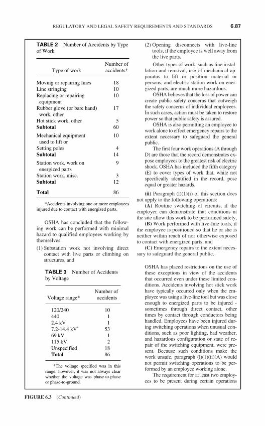
OSHA has concluded that the follow-ing work can be performed with minimalhazard to qualified employees working bythemselves:
(1) Substation work not involving directcontact with live parts or climbing onstructures, and
(2) Opening disconnects with live-linetools, if the employee is well away fromthe live parts.
Other types of work, such as line instal-lation and removal, use of mechanical ap-paratus to lift or position material orpersons, and electric station work on ener-gized parts, are much more hazardous.
OSHA believes that the loss of power cancreate public safety concerns that outweighthe safety concerns of individual employees.In such cases, action must be taken to restorepower so that public safety is assured.
OSHA is also permitting an employee towork alone to effect emergency repairs to theextent necessary to safeguard the generalpublic.
The first four work operations (A throughD) are those that the record demonstrates ex-pose employees to the greatest risk of electricshock. OSHA has included the fifth category(E) to cover types of work that, while notspecifically identified in the record, poseequal or greater hazards.
(ii) Paragraph (l)(1)(i) of this section doesnot apply to the following operations:
(A) Routine switching of circuits, if theemployer can demonstrate that conditions atthe site allow this work to be performed safely,
(B) Work performed with live-line tools, ifthe employee is positioned so that he or she isneither within reach of nor otherwise exposedto contact with energized parts, and
(C) Emergency repairs to the extent neces-sary to safeguard the general public.
OSHA has placed restrictions on the use ofthese exceptions in view of the accidentsthat occurred even under these limited con-ditions. Accidents involving hot stick workhave typically occurred only when the em-ployee was using a live-line tool but was closeenough to energized parts to be injured -sometimes through direct contact, othertimes by contact through conductors beinghandled. Employees have been injured dur-ing switching operations when unusual con-ditions, such as poor lighting, bad weather,and hazardous configuration or state of re-pair of the switching equipment, were pre-sent. Because such conditions make thework unsafe, paragraph (l)(1)(ii)(A) wouldnot permit switching operations to be per-formed by an employee working alone.
The requirement for at least two employ-ees to be present during certain operations
REGULATORY AND LEGAL SAFETY REQUIREMENTS AND STANDARDS 6.87
FIGURE 6.3 (Continued)
TABLE 2 Number of Accidents by Typeof Work
Number of Type of work accidents*
Moving or repairing lines 18Line stringing 10Replacing or repairing 10
equipmentRubber glove (or bare hand) 17
work, otherHot stick work, other 5Subtotal 60
Mechanical equipment 10used to lift or
Setting poles 4Subtotal 14
Station work, work on 9energized parts
Station work, misc. 3Subtotal 12
Total 86
*Accidents involving one or more employeesinjured due to contact with energized parts.
TABLE 3 Number of Accidentsby Voltage
Number ofVoltage range* accidents
120/240 10440 12.4 kV 17.2-14.4 kV* 5369 kV 1115 kV 2Unspecified 18Total 86
*The voltage specified was in thisrange; however, it was not always clearwhether the voltage was phase-to-phaseor phase-to-ground.
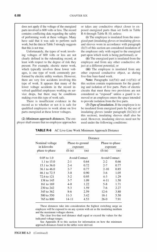
does not apply if the voltage of the energizedparts involved is 600 volts or less. The recordcontains conflicting data regarding the safetyof performing work at these voltages. Manyhave said that it was safe to perform suchwork, but the data in Table 3 strongly suggeststhat this is not true.
Unfortunately, the types of work involv-ing voltages of 600 volts or less are notclearly defined in the rulemaking record, atleast with respect to the degree of risk theypresent. For example, electric meter work,which typically involves these lower volt-ages, is one type of work commonly per-formed by electric utility workers. However,there are very few accidents involving thistype of work. It appears that many of thelower voltage accidents in the record in-volved qualified employees working on ser-vice drops, but there may be conditionsmaking even this type of work safe.
There is insufficient evidence in therecord as to whether or not it is safe forqualified employees to work alone on liveparts energized at these lower voltages.
(2) Minimum approach distances. The em-ployer shall ensure that no employee approaches
or takes any conductive object closer to ex-posed energized parts than set forth in TableR-6 through Table R-10, unless:
(i) The employee is insulated from the ener-gized part (insulating gloves or insulating glovesand sleeves worn in accordance with paragraph(l)(3) of this section are considered insulation ofthe employee only with regard to the energizedpart upon which work is being performed), or
(ii) The energized part is insulated from theemployee and from any other conductive ob-ject at a different potential, or
(iii) The employee is insulated from anyother exposed conductive object, as duringlive-line bare-hand work.
Note: Paragraphs (u)(5)(i) and (v)(5)(i) ofthis section contain requirements for the guard-ing and isolation of live parts. Parts of electriccircuits that meet these two provisions are notconsidered as “exposed” unless a guard is re-moved or an employee enters the space intendedto provide isolation from the live parts.
(3) Type of insulation. If the employee is tobe insulated from energized parts by the use ofinsulating gloves (under paragraph (l)(2)(i) ofthis section), insulating sleeves shall also beused. However, insulating sleeves need not beused under the following conditions:
6.88 CHAPTER SIX
FIGURE 6.3 (Continued)
TABLE R-6 AC Live-Line Work Minimum Approach Distance
Distance
Nominal voltage Phase-to-ground Phase-to-phasein kilovolts exposure exposure
phase to phase (ft-in) (m) (ft-in) (m)
0.05 to 1.0 Avoid Contact Avoid Contact1.1 to 15.0 2-1 0.64 2-2 0.66
15.1 to 36.0 2-4 0.72 2-7 0.7736.1 to 46.0 2-7 0.77 2-10 0.8546.1 to 72.5 3-0 0.90 3-6 1.0572.6 to 121 3-2 0.95 4-3 1.29138 to 145 3-7 1.09 4-11 1.50161 to 169 4-0 1.22 5-8 1.71230 to 242 5-3 1.59 7-6 2.27345 to 362 8-6 2.59 12-6 3.80500 to 550 11-3 3.42 18-1 5.50765 to 800 14-11 4.53 26-0 7.91
These distances take into consideration the highest switching surge anemployee will be exposed to on any system with air as the insulating mediumand the maximum voltages shown.
The clear live-line tool distance shall equal or exceed the values for theindicated voltage ranges.
See Appendix B to this section for information on how the minimumapproach distances listed in the tables were derived.
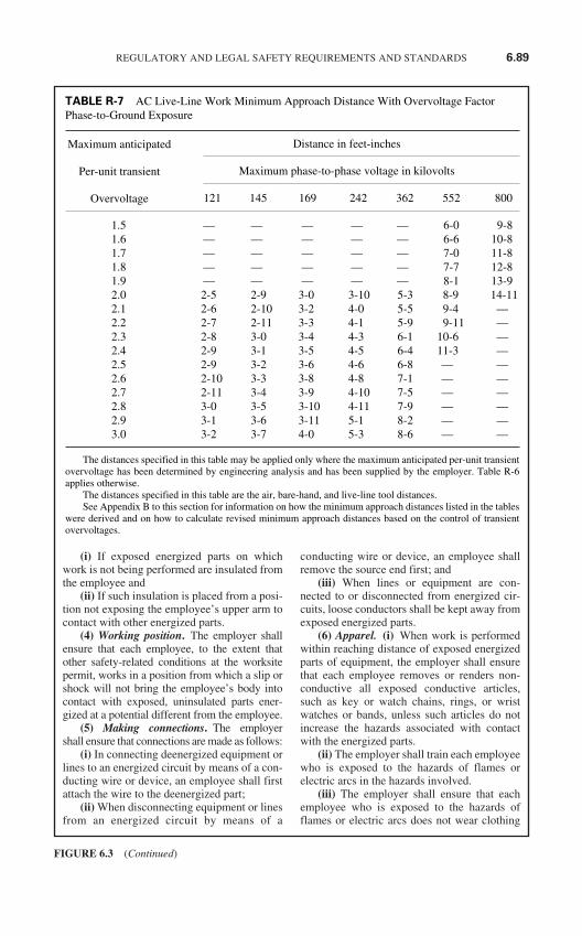
(i) If exposed energized parts on whichwork is not being performed are insulated fromthe employee and
(ii) If such insulation is placed from a posi-tion not exposing the employee’s upper arm tocontact with other energized parts.
(4) Working position. The employer shallensure that each employee, to the extent thatother safety-related conditions at the worksitepermit, works in a position from which a slip orshock will not bring the employee’s body intocontact with exposed, uninsulated parts ener-gized at a potential different from the employee.
(5) Making connections. The employershall ensure that connections are made as follows:
(i) In connecting deenergized equipment orlines to an energized circuit by means of a con-ducting wire or device, an employee shall firstattach the wire to the deenergized part;
(ii) When disconnecting equipment or linesfrom an energized circuit by means of a
conducting wire or device, an employee shallremove the source end first; and
(iii) When lines or equipment are con-nected to or disconnected from energized cir-cuits, loose conductors shall be kept away fromexposed energized parts.
(6) Apparel. (i) When work is performedwithin reaching distance of exposed energizedparts of equipment, the employer shall ensurethat each employee removes or renders non-conductive all exposed conductive articles,such as key or watch chains, rings, or wristwatches or bands, unless such articles do notincrease the hazards associated with contactwith the energized parts.
(ii) The employer shall train each employeewho is exposed to the hazards of flames orelectric arcs in the hazards involved.
(iii) The employer shall ensure that eachemployee who is exposed to the hazards offlames or electric arcs does not wear clothing
REGULATORY AND LEGAL SAFETY REQUIREMENTS AND STANDARDS 6.89
FIGURE 6.3 (Continued)
TABLE R-7 AC Live-Line Work Minimum Approach Distance With Overvoltage FactorPhase-to-Ground Exposure
Distance in feet-inches
Maximum phase-to-phase voltage in kilovolts
121 145 169 242 362 552 800
1.5 — — — — — 6-0 9-81.6 — — — — — 6-6 10-81.7 — — — — — 7-0 11-81.8 — — — — — 7-7 12-81.9 — — — — — 8-1 13-92.0 2-5 2-9 3-0 3-10 5-3 8-9 14-112.1 2-6 2-10 3-2 4-0 5-5 9-4 —2.2 2-7 2-11 3-3 4-1 5-9 9-11 —2.3 2-8 3-0 3-4 4-3 6-1 10-6 —2.4 2-9 3-1 3-5 4-5 6-4 11-3 —2.5 2-9 3-2 3-6 4-6 6-8 — —2.6 2-10 3-3 3-8 4-8 7-1 — —2.7 2-11 3-4 3-9 4-10 7-5 — —2.8 3-0 3-5 3-10 4-11 7-9 — —2.9 3-1 3-6 3-11 5-1 8-2 — —3.0 3-2 3-7 4-0 5-3 8-6 — —
The distances specified in this table may be applied only where the maximum anticipated per-unit transientovervoltage has been determined by engineering analysis and has been supplied by the employer. Table R-6applies otherwise.
The distances specified in this table are the air, bare-hand, and live-line tool distances.See Appendix B to this section for information on how the minimum approach distances listed in the tables
were derived and on how to calculate revised minimum approach distances based on the control of transientovervoltages.
Maximum anticipated
Per-unit transient
Overvoltage
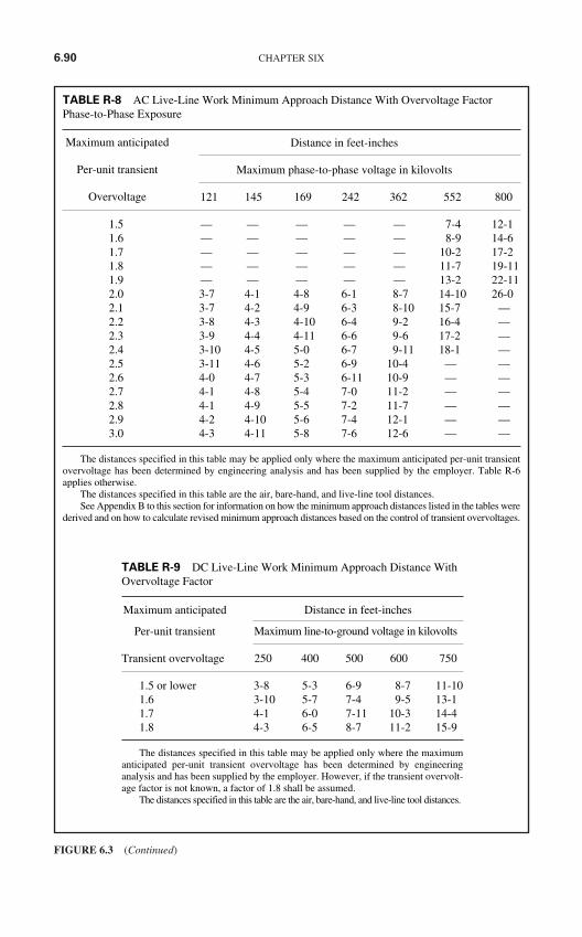
6.90 CHAPTER SIX
FIGURE 6.3 (Continued)
TABLE R-8 AC Live-Line Work Minimum Approach Distance With Overvoltage FactorPhase-to-Phase Exposure
Distance in feet-inches
Maximum phase-to-phase voltage in kilovolts
121 145 169 242 362 552 800
1.5 — — — — — 7-4 12-11.6 — — — — — 8-9 14-61.7 — — — — — 10-2 17-21.8 — — — — — 11-7 19-111.9 — — — — — 13-2 22-112.0 3-7 4-1 4-8 6-1 8-7 14-10 26-02.1 3-7 4-2 4-9 6-3 8-10 15-7 —2.2 3-8 4-3 4-10 6-4 9-2 16-4 —2.3 3-9 4-4 4-11 6-6 9-6 17-2 —2.4 3-10 4-5 5-0 6-7 9-11 18-1 —2.5 3-11 4-6 5-2 6-9 10-4 — —2.6 4-0 4-7 5-3 6-11 10-9 — —2.7 4-1 4-8 5-4 7-0 11-2 — —2.8 4-1 4-9 5-5 7-2 11-7 — —2.9 4-2 4-10 5-6 7-4 12-1 — —3.0 4-3 4-11 5-8 7-6 12-6 — —
The distances specified in this table may be applied only where the maximum anticipated per-unit transientovervoltage has been determined by engineering analysis and has been supplied by the employer. Table R-6applies otherwise.
The distances specified in this table are the air, bare-hand, and live-line tool distances.See Appendix B to this section for information on how the minimum approach distances listed in the tables were
derived and on how to calculate revised minimum approach distances based on the control of transient overvoltages.
Maximum anticipated
Per-unit transient
Overvoltage
TABLE R-9 DC Live-Line Work Minimum Approach Distance WithOvervoltage Factor
Distance in feet-inches
Maximum line-to-ground voltage in kilovolts
Transient overvoltage 250 400 500 600 750
1.5 or lower 3-8 5-3 6-9 8-7 11-101.6 3-10 5-7 7-4 9-5 13-11.7 4-1 6-0 7-11 10-3 14-41.8 4-3 6-5 8-7 11-2 15-9
The distances specified in this table may be applied only where the maximumanticipated per-unit transient overvoltage has been determined by engineeringanalysis and has been supplied by the employer. However, if the transient overvolt-age factor is not known, a factor of 1.8 shall be assumed.
The distances specified in this table are the air, bare-hand, and live-line tool distances.
Maximum anticipated
Per-unit transient
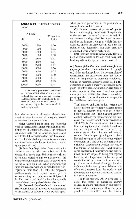
that, when exposed to flames or electric arcs,could increase the extent of injury that wouldbe sustained by the employee.
Note: Clothing made from the followingtypes of fabrics, either alone or in blends, is pro-hibited by this paragraph, unless the employercan demonstrate that the fabric has been treatedto withstand the conditions that may be encoun-tered or that the clothing is worn in such a man-ner as to eliminate the hazard involved: acetate,nylon, polyester, rayon.
(7) Fuse handling. When fuses must be in-stalled or removed with one or both terminalsenergized at more than 300 volts or with ex-posed parts energized at more than 50 volts, theemployer shall ensure that tools or gloves ratedfor the voltage are used. When expulsion-typefuses are installed with one or both terminals en-ergized at more than 300 volts, the employershall ensure that each employee wears eye pro-tection meeting the requirements of Subpart I ofthis Part, uses a tool rated for the voltage, and isclear of the exhaust path of the fuse barrel.
(8) Covered (noninsulated) conductors.The requirements of this section which pertainto the hazards of exposed live parts also apply
when work is performed in the proximity ofcovered (noninsulated) wires.
(9) Noncurrent-carrying metal parts.Noncurrent-carrying metal parts of equipmentor devices, such as transformer cases and cir-cuit breaker housings, shall be treated as ener-gized at the highest voltage to which they areexposed, unless the employer inspects the in-stallation and determines that these parts aregrounded before work is performed.
(10) Opening circuits under load. Devicesused to open circuits under load conditions shallbe designed to interrupt the current involved.
(m) Deenergizing lines and equipment for em-ployee protection. (1) Application. Paragraph(m) of this section applies to the deenergizing oftransmission and distribution lines and equip-ment for the purpose of protecting employees.Control of hazardous energy sources used in thegeneration of electric energy is covered in para-graph (d) of this section. Conductors and parts ofelectric equipment that have been deenergizedunder procedures other than those required byparagraph (d) or (m) of this section, as applica-ble, shall be treated as energized.
Transmission and distribution systems aredifferent from other energy systems foundin general industry or even in the electricutility industry itself. The hazardous energycontrol methods for these systems are nec-essarily different from those covered under1910.269(d). Transmission and distributionlines and equipment are installed outdoorsand are subject to being reenergized bymeans other than the normal energysources. For example, lightning can strike aline and energize an otherwise deenergizedconductor, or a line could be energized byunknown cogeneration sources not underthe control of the employer. Additionally,some deenergized transmission and distrib-ution lines are subject to being reenergizedby induced voltage from nearby energizedconductors or by contact with other ener-gized sources of electrical energy. Anotherdifference is that energy control devices areoften very remote from the worksite andare frequently under the centralized controlof a system operator.
For these reasons, OSHA proposed tocover the control of hazardous energysources related to transmission and distrib-ution systems separately. Because para-graph (m) covers this area, the general
REGULATORY AND LEGAL SAFETY REQUIREMENTS AND STANDARDS 6.91
FIGURE 6.3 (Continued)
TABLE R-10 Altitude CorrectionFactor
AltitudeCorrection
ft m factor
3000 900 1.004000 1200 1.025000 1500 1.056000 1800 1.087000 2100 1.118000 2400 1.149000 2700 1.17
10000 3000 1.2012000 3600 1.2514000 4200 1.3016000 4800 1.3518000 5400 1.3920000 6000 1.44
If the work is performed at elevationsgreater than 3000 ft (900 m) above meansea level, the minimum approach distanceshall be determined by multiplying the dis-tances in 1 through 1 by the correction fac-tor corresponding to the altitude at whichwork is performed.
requirements for hazardous energy controlin paragraph (d) of final 1910.269 do notapply to the disconnection of transmissionand distribution lines and equipment fromsources of electrical energy.
OSHA firmly believes that certain proce-dures must be followed for deenergizing liveparts at any voltage over 50 volts if employ-ees will be in contact with the parts duringthe course of work. Contact with electric cir-cuit parts energized at 600 volts or less canbe as fatal as contact with higher voltages.The basic steps necessary for deenergizingelectric circuits are the same regardless ofvoltage - first, the disconnecting means forthe circuit must be opened; second, a methodof securing the disconnecting means fromaccidental closure must be used; third, thecircuit must be tested to ensure that it is infact deenergized; and, fourth, measures (suchas grounding) must be used to ensure that nohazardous voltage can be impressed on thecircuit while employees are working. Theseare the same steps that are set forth, without avoltage limitation, in the NESC Section 423.
(2) General. (i) If a system operator is incharge of the lines or equipment and theirmeans of disconnection, all of the requirementsof paragraph (m)(3) of this section shall be ob-served, in the order given.
(ii) If no system operator is in charge of thelines or equipment and their means of disconnec-tion, one employee in the crew shall be desig-nated as being in charge of the clearance. All ofthe requirements of paragraph (m)(3) of this sec-tion apply, in the order given, except as providedin paragraph (m)(2)(iii) of this section. The em-ployee in charge of the clearance shall take theplace of the system operator, as necessary.
(iii) If only one crew will be working on thelines or equipment and if the means of discon-nection is accessible and visible to and underthe sole control of the employee in charge ofthe clearance, paragraphs (m)(3)(i), (m)(3)(iii),(m)(3)(iv), (m)(3)(viii), and (m)(3)(xii) of thissection do not apply. Additionally, tags re-quired by the remaining provisions of para-graph (m)(3) of this section need not be used.
(iv) Any disconnecting means that are ac-cessible to persons outside the employer’s con-trol (for example, the general public) shall berendered inoperable while they are open for thepurpose of protecting employees.
(3) De-energizing lines and equipment.(i) A designated employee shall make a request ofthe system operator to have the particular section
of line or equipment deenergized. The desig-nated employee becomes the employee in charge(as this term is used in paragraph (m)(3) of thissection) and is responsible for the clearance.
(ii) All switches, disconnectors, jumpers,taps, and other means through which knownsources of electric energy may be supplied to theparticular lines and equipment to be deenergizedshall be opened. Such means shall be renderedinoperable, unless its design does not so permit,and tagged to indicate that employees are atwork.
(iii) Automatically and remotely controlledswitches that could cause the opened discon-necting means to close shall also be tagged atthe point of control. The automatic or remotecontrol feature shall be rendered inoperable,unless its design does not so permit.
(iv) Tags shall prohibit operation of the dis-connecting means and shall indicate that em-ployees are at work.
(v) After the applicable requirements in para-graphs (m)(3)(i) through (m)(3)(iv) of this sec-tion have been followed and the employee incharge of the work has been given a clearance bythe system operator, the lines and equipment tobe worked shall be tested to ensure that they aredeenergized.
(vi) Protective grounds shall be installed asrequired by paragraph (n) of this section.
(vii) After the applicable requirements ofparagraphs (m)(3)(i) through (m)(3)(vi) of thissection have been followed, the lines and equip-ment involved may be worked as deenergized.
(viii) If two or more independent crews willbe working on the same lines or equipment, eachcrew shall independently comply with the re-quirements in paragraph (m)(3) of this section.
(ix) To transfer the clearance, the employeein charge (or, if the employee in charge is forcedto leave the worksite due to illness or other emer-gency, the employee’s supervisor) shall informthe system operator; employees in the crew shallbe informed of the transfer; and the new em-ployee in charge shall be responsible for theclearance.
(x) To release a clearance, the employee incharge shall:
(A) Notify employees under his or her di-rection that the clearance is to be released;
(B) Determine that all employees in thecrew are clear of the lines and equipment;
(C) Determine that all protective groundsinstalled by the crew have been removed; and
(D) Report this information to the systemoperator and release the clearance.
6.92 CHAPTER SIX
FIGURE 6.3 (Continued)
(xi) The person releasing a clearance shallbe the same person that requested the clear-ance, unless responsibility has been transferredunder paragraph (m)(3)(ix) of this section.
(xii) Tags may not be removed unless theassociated clearance has been released underparagraph (m)(3)(x) of this section.
(xiii) Only after all protective grounds havebeen removed, after all crews working on thelines or equipment have released their clear-ances, after all employees are clear of the linesand equipment, and after all protective tags havebeen removed from a given point of disconnec-tion, may action be initiated to reenergize thelines or equipment at that point of disconnection.
Action may be taken to reenergize the linesor equipment only after grounds and tagshave been removed, after all clearances havebeen released, and after all employees are inthe clear. This protects employees from thepossibility that the line or equipment couldbe reenergized while employees are still atwork.
The Agency did not intend for this provi-sion to require the removal of all tags from alldisconnecting means before any of themcould be reclosed. It was intended to requirethat all tags for any particular switch be re-moved before that switch was closed. It isvery important in a tagging system that no en-ergy isolating device be returned to a positionallowing energy flow if there are any tags onit that are protecting employees.
(n) Grounding for the protection of employ-ees. (1) Application. Paragraph (n) of thissection applies to the grounding of transmis-sion and distribution lines and equipment forthe purpose of protecting employees. Para-graph (n)(4) of this section also applies to theprotective grounding of other equipment as re-quired elsewhere in this section.
Sometimes, normally energized lines andequipment which have been deenergized topermit employees to work become acciden-tally energized. This can happen in severalways, for example, by contact with anotherenergized circuit, by voltage backfeed from acustomer’s cogeneration installation, bylightning contact, or by failure of the clear-ance system outlined in 1910.269(m).
Transmission and distribution lines andequipment are normally installed outdoorswhere they are exposed to damage from theweather and from actions taken by members
of the general public. Many utility poles areinstalled alongside roadways where theymay be struck by motor vehicles. Distribu-tion lines have been damaged by fallingtrees, and transmission line insulators havebeen used for target practice. Additionally,customers fed by a utility company’s distrib-ution line may have cogeneration or backupgeneration capability, sometimes without theutility company’s knowledge. All these fac-tors can reenergize a deenergized transmis-sion or distribution line or equipment.Energized lines can be knocked down ontodeenergized lines. A backup generator or acogenerator can cause voltage backfeed onthe deenergized power line. Lastly, lightning,even miles from the worksite, can reenergizea line. All of these problems pose hazards toemployees working on deenergized trans-mission and distribution lines and equip-ment. In fact, these problems have been afactor in 14 of the accidents in the record.
Grounding the lines and equipment isused to protect employees from injury,should such reenergizing occur. Groundingalso provides protection against inducedvoltages and static charges on a line.(These induced and static voltages can behigh enough to endanger employees, eitherdirectly from electric shock or indirectlyfrom involuntary reaction.)
Grounding, as a temporary protectivemeasure, involves connecting the deener-gized lines and equipment to earth throughconductors. As long as the conductors re-main deenergized, this maintains the linesand equipment at the same potential as theearth. However, if voltage is impressed on aline, the voltage on the grounded line rises toa value dependent upon the impressed volt-age, the impedance between its source andthe grounding point, and the impedance ofthe grounding conductor.
Various techniques are used to limit thevoltage to which an employee working on agrounded line would be exposed. Bonding isone of these techniques. Conductive objectswithin the reach of the employee are bondedtogether to create an equipotential work areafor the employee. Within this area of equalpotentials, voltage differences are limited toa safe value.
As noted in paragraph (n)(1), entire para-graph (n) applies to the grounding of deener-gized transmission and distribution lines and
REGULATORY AND LEGAL SAFETY REQUIREMENTS AND STANDARDS 6.93
FIGURE 6.3 (Continued)
equipment for the purpose of protecting em-ployees. Additionally, paragraph (n)(1) indi-cates that paragraph (n)(4) applies to theprotective grounding of non-electrical equip-ment, such as aerial lift trucks, as well. Undernormal conditions, such equipment wouldnot be connected to a source of electric en-ergy. However, to protect employees in caseof accidental contact of the equipment withlive parts, protective grounding is requiredelsewhere in the; and, to ensure the adequacyof this grounding, the provisions of para-graph (n)(4) must be followed.
Additional comments did not provideany information indicating that work on un-grounded deenergized equipment normallyoperating at 600 volts or less is safe. TheAgency is particularly concerned that unde-tected voltage from a customer’s generatingsystem may backfeed the low voltage circuitand energize the line while the employee isworking. Several of the accidents in therecord occurred in this manner. Although theemployee usually happened to be working onthe high voltage side of a transformer in thesecases, a similar result would have occurredhad the worker been contacting the low volt-age side. For these reasons, no voltage limi-tation has been included in paragraph (n)(1)of final 1910.269.
(2) General. For the employee to work linesor equipment as deenergized, the lines or equip-ment shall be deenergized under the provisionsof paragraph (m) of this section and shall begrounded as specified in paragraphs (n)(3)through (n)(9) of this section. However, if theemployer can demonstrate that installation of aground is impracticable or that the conditions re-sulting from the installation of a ground wouldpresent greater hazards than working withoutgrounds, the lines and equipment may be treatedas deenergized provided all of the following con-ditions are met:
(i) The lines and equipment have beendeenergized under the provisions of paragraph(m) of this section.
(ii) There is no possibility of contact withanother energized source.
(iii) The hazard of induced voltage is notpresent.
Grounding may be omitted only if the in-stallation of a ground is impracticable (suchas during the initial stages of work on un-derground cables, when the conductor is notexposed for grounding) or if the conditions
resulting from the installation of a groundwould introduce more serious hazards thanwork without grounds. It is expected thatconditions warranting the absence of pro-tective grounds will be relatively rare.
If grounds are not installed and the linesand equipment are to be treated as deener-gized, however, precautions have to be ob-served, and certain conditions must be met.Obviously, the lines and equipment stillmust be deenergized by the procedures of1910.269(m). Also, there may be no possi-bility of contact with another source of volt-age, and the hazard of induced voltage maynot be present. Since these precautions andconditions do not protect against the possi-ble reenergizing of the lines or equipmentunder all conditions, the omission ofgrounding is permitted only in very limitedcircumstances.
(3) Equipotential zone. Temporary protec-tive grounds shall be placed at such locationsand arranged in such a manner as to preventeach employee from being exposed to haz-ardous differences in electrical potential.
Paragraph (n)(3) allows employers and em-ployees to use whatever grounding methodthey prefer as long as employees are pro-tected. For employees working at elevatedpositions on poles and towers, single pointgrounding may be necessary, together withgrounding straps to provide an equipotentialzone for the worker. Employees in insulatedaerial lifts working at midspan between twoconductor supporting structures may be pro-tected by grounding at convenient points onboth sides of the work area. Bonding the aer-ial lift to the grounded conductor will ensurethat the employee remains at the potential ofthe conductor in case of a fault. Other meth-ods may be necessary to protect workers onthe ground, including grounding mats and in-sulating platforms. The Agency believes thatthis performance-oriented approach will pro-vide the flexibility needed by employers, butwill afford the best protection to employees.
(4) Protective grounding equipment. (i) Pro-tective grounding equipment shall be capable ofconducting the maximum fault current thatcould flow at the point of grounding for the timenecessary to clear the fault. This equipment shallhave an ampacity greater than or equal to that ofNo. 2 AWG copper.
So that the protective grounding equip-ment does not fail, it is required to have an
6.94 CHAPTER SIX
FIGURE 6.3 (Continued)
ampacity high enough so that the fault cur-rent would be carried for the amount of timenecessary to allow protective devices to in-terrupt the circuit.
Note: Guidelines for protective groundingequipment are contained in American Societyfor Testing and Materials Standard Specifica-tions for Temporary Grounding Systems to beUsed on De-Energized Electric Power Linesand Equipment, ASTM F855-1990.
(ii) Protective grounds shall have an imped-ance low enough to cause immediate operationof protective devices in case of accidental ener-gizing of the lines or equipment.
Paragraphs (n)(4)(i) and (n)(4)(ii) help en-sure the prompt clearing of the circuit sup-plying voltage to the point where theemployee is working. Thus, the groundingequipment limits the duration and reducesthe severity of any electric shock, though itdoes not itself prevent shock from occurring.
(5) Testing. Before any ground is in-stalled, lines and equipment shall be tested andfound absent of nominal voltage, unless a pre-viously installed ground is present.
This requirement prevents energized equip-ment from being grounded, which could re-sult in injury to the employee installing theground.
(6) Order of connection. When a groundis to be attached to a line or to equipment, theground-end connection shall be attached first,and then the other end shall be attached bymeans of a live-line tool.
(7) Order of removal. When a ground is tobe removed, the grounding device shall be re-moved from the line or equipment using a live-line tool before the ground-end connection isremoved.
Paragraphs (n)(6) and (n)(7) set forth the pro-cedure for installing and removing grounds.To protect employees in the event that the“deenergized” equipment to be grounded isor becomes energized, the standard requiresthe “equipment end” of the grounding deviceto be applied last and removed first and that alive-line tool be used for both procedures inorder to protect workers.
OSHA will consider any device that isinsulated for the voltage and that allows anemployee to apply or remove the groundfrom a safe position to be a live-line tool forthe purposes of 1910.269(n)(6) and (n)(7).It should be noted that, during the periods
before the ground is installed and after it isremoved, the line or equipment involvedmust be considered as energized (under para-graph (l)(1)). As a result, the minimum ap-proach distances specified in paragraph (l)(2)apply when grounds are installed or re-moved.
(8) Additional precautions. When work isperformed on a cable at a location remote fromthe cable terminal, the cable may not begrounded at the cable terminal if there is a pos-sibility of hazardous transfer of potentialshould a fault occur.
With certain underground cable installa-tions, a fault at one location along the cablecan create a substantial potential differencebetween the earth at that location and theearth at other locations. Under normal con-ditions, this is not a hazard. However, if anemployee is in contact with a remote ground(by being in contact with a conductor that isgrounded at a remote station), he or she canbe exposed to the difference in potential (be-cause he or she is also in contact with thelocal ground). To protect employees in suchsituations, paragraph (n)(8) prohibits ground-ing cables at remote locations if a hazardouspotential transfer could occur under faultconditions.
(9) Removal of grounds for test. Groundsmay be removed temporarily during tests. Dur-ing the test procedure, the employer shall en-sure that each employee uses insulatingequipment and is isolated from any hazards in-volved, and the employer shall institute any ad-ditional measures as may be necessary toprotect each exposed employee in case the pre-viously grounded lines and equipment becomeenergized.
(o) Testing and test facilities. (1) Application.Paragraph (o) of this section provides for safework practices for high-voltage and high-powertesting performed in laboratories, shops, andsubstations, and in the field and on electric trans-mission and distribution lines and equipment. Itapplies only to testing involving interim mea-surements utilizing high voltage, high power, orcombinations of both, and not to testing involv-ing continuous measurements as in routine me-tering, relaying, and normal line work.
Note: Routine inspection and maintenancemeasurements made by qualified employees areconsidered to be routine line work and are notincluded in the scope of paragraph (o) of this
REGULATORY AND LEGAL SAFETY REQUIREMENTS AND STANDARDS 6.95
FIGURE 6.3 (Continued)
section, as long as the hazards related to the useof intrinsic high-voltage or high-power sourcesrequire only the normal precautions associatedwith routine operation and maintenance workrequired in the other paragraphs of this section.Two typical examples of such excluded testwork procedures are “phasing-out” testing andtesting for a “no-voltage” condition.
For the purposes of these requirements, high-voltage testing is assumed to involve voltagesources having sufficient energy to cause in-jury and having magnitudes generally in ex-cess of 1000 volts, nominal. High-powertesting involves sources where fault currents,load currents, magnetizing currents, or linedropping currents are used for testing, eitherat the rated voltage of the equipment undertest or at lower voltages. Paragraph (o) cov-ers such testing in laboratories, in shops andsubstations, and in the field and on transmis-sion and distribution lines.
Examples of typical special tests inwhich either high-voltage sources or high-power sources are used as part of operationand maintenance of electric power genera-tion, transmission, and distribution systemsinclude cable-fault locating, large capacitiveload tests, high current fault-closure tests, in-sulation resistance and leakage tests, direct-current proof tests, and other tests requiringdirect connection to power lines.
(2) General requirements. (i) The em-ployer shall establish and enforce work prac-tices for the protection of each worker from thehazards of high-voltage or high-power testingat all test areas to temporary and permanent.Such work practices shall include, as a mini-mum, test area guarding, grounding, and thesafe use of measuring and control circuits. Ameans providing for periodic safety checks offield test areas shall also be included. (Seeparagraph (o)(6) of this section.)
Paragraph (o)(2)(i) requires employers to es-tablish work practices governing employeesengaged in certain testing activities. Thesework practices are intended to delineate pre-cautions that employees must observe forprotection from the hazards of high-voltageor high-power testing. For example, if high-voltage sources are used in the testing, em-ployees are required to follow the safetypractices established under paragraph(o)(2)(i) to protect against such typical haz-ards as inadvertent arcing or voltage over-
stress destruction, as well as accidentalcontact with objects which have becomeresidually charged by induced voltage fromelectric field exposure. If high-power sourcesare used in the testing, employees are re-quired to follow established safety practicesto protect against such typical hazards asground voltage rise as well as exposure to ex-cessive electromagnetically-caused physicalforces associated with the passage of heavycurrent.
These practices apply to work performedat both permanent and temporary test areas(that is, areas permanently located in the con-trolled environment of a laboratory or shopand in areas temporarily located in a non-controlled field environment). At a mini-mum, the safety work practices are required tocover the following types of test-associatedactivities:
(1) Guarding the test area to prevent inad-vertent contact with energized parts,
(2) Safe grounding practices to be observed,(3) Precautions to be taken in the use of
control and measuring circuits, and(4) Periodic checks of field test areas.
(ii) Employees shall be trained in safe workpractices upon their initial assignment to the testarea, with periodic reviews and updates providedas required by paragraph (a)(2) of this section.
Paragraph (o)(2)(ii) complements the gen-eral rule on the use of safe work practices intest areas with a requirement that all employ-ees involved in this type of work be trained inthese safety test practices. This paragraphfurther requires a periodic review of thesepractices to be conducted from time to timeas a means of providing reemphasis andupdating.
Although specific work practices used intest areas are generally unique to the particu-lar test being conducted, three basic elementsaffecting safety are commonly found to somedegree at all test sites: guarding, grounding,and the safe utilization of control and mea-suring circuits. By considering safe workpractices in these three categories, OSHAhas attempted to achieve a performance-ori-ented standard applicable to high-voltageand high-power testing and test facilities.
(3) Guarding of test areas. (i) Permanenttest areas shall be guarded by walls, fences, orbarriers designed to keep employees out of thetest areas.
6.96 CHAPTER SIX
FIGURE 6.3 (Continued)
OSHA believes that guarding can best beachieved when it is provided both around andwithin test areas. By controlling access to allparts that are likely to become energized byeither direct or inductive coupling, the stan-dard will prevent accidental contact by employ-ees. Paragraph (o)(3)(i) requires permanenttest areas to be guarded by having them com-pletely enclosed by walls or some other typeof physical barrier.
(ii) In field testing, or at a temporary testsite where permanent fences and gates are notprovided, one of the following means shall beused to prevent unauthorized employees fromentering:
(A) The test area shall be guarded by theuse of distinctively colored safety tape that issupported approximately waist high and towhich safety signs are attached,
(B) The test area shall be guarded by a bar-rier or barricade that limits access to the testarea to a degree equivalent, physically and vi-sually, to the barricade specified in paragraph(o)(3)(ii)(A) of this section, or
(C) The test area shall be guarded by one ormore test observers stationed so that the entirearea can be monitored.
In the case of field testing, paragraph(o)(3)(ii) attempts to achieve a level of safetyfor temporary test sites comparable to thatachieved in laboratory test areas. For theseareas, a barricade of tapes and cones or ob-servation by an attendant are acceptablemethods of guarding.
(iii) The barriers required by paragraph(o)(3)(ii) of this section shall be removed whenthe protection they provide is no longer needed.
Since the effectiveness of the temporaryguarding means can be severely compro-mised by failing to remove it when it is notrequired, frequent safety checks must bemade to monitor its use. For example, leav-ing barriers in place for a week at a timewhen testing is performed only an hour ortwo per day is likely to result in disregard forthe barriers. For this reason, paragraph(o)(3)(iii) requires the temporary barriers tobe removed when they are no longer needed.
(iv) Guarding shall be provided within testareas to control access to test equipment or toapparatus under test that may become ener-gized as part of the testing by either direct orinductive coupling, in order to prevent acciden-tal employee contact with energized parts.
Within test areas, whether temporary orpermanent, additional safety can beachieved by observing the guarding prac-tices that control access to test areas. Para-graph (o)(3)(iv) therefore requires that suchguarding be provided if the test equipmentor apparatus under test may become ener-gized as part of the testing by either director inductive coupling. A combination ofguards and barriers, preferably interlocked,is intended to provide protection to all em-ployees in the vicinity.
(4) Grounding practices. (i) The employershall establish and implement safe groundingpractices for the test facility.
(A) All conductive parts accessible to thetest operator during the time the equipment isoperating at high voltage shall be maintained atground potential except for portions of theequipment that are isolated from the test opera-tor by guarding.
(B) Wherever ungrounded terminals of testequipment or apparatus under test may be pre-sent, they shall be treated as energized until de-termined by tests to be deenergized.
Suitable grounding is another importantwork practice that can be employed for theprotection of personnel from the hazards ofhigh-voltage or high-power testing. If highcurrents are intentionally employed in thetesting, an isolated ground-return conductor,adequate for the service, is required so thatno intentional passage of heavy current, withits attendant voltage rise, will occur in theground grid or in the earth. Another safetyconsideration involving grounding is that allconductive parts accessible to the test opera-tor during the time that the equipment is op-erating at high voltage be maintained atground potential, except portions of theequipment that are isolated from the test op-erator by suitable guarding. Paragraph (o)(4)of final 1910.269 contains requirements forproper grounding at test sites.
(ii) Visible grounds shall be applied, eitherautomatically or manually with properly insu-lated tools, to the high-voltage circuits afterthey are deenergized and before work is per-formed on the circuit or item or apparatusunder test. Common ground connections shallbe solidly connected to the test equipment andthe apparatus under test.
(iii) In high-power testing, an isolatedground-return conductor system shall be pro-vided so that no intentional passage of current,
REGULATORY AND LEGAL SAFETY REQUIREMENTS AND STANDARDS 6.97
FIGURE 6.3 (Continued)
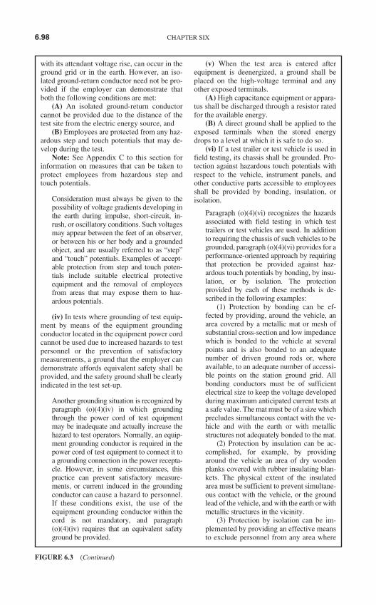
with its attendant voltage rise, can occur in theground grid or in the earth. However, an iso-lated ground-return conductor need not be pro-vided if the employer can demonstrate thatboth the following conditions are met:
(A) An isolated ground-return conductorcannot be provided due to the distance of thetest site from the electric energy source, and
(B) Employees are protected from any haz-ardous step and touch potentials that may de-velop during the test.
Note: See Appendix C to this section forinformation on measures that can be taken toprotect employees from hazardous step andtouch potentials.
Consideration must always be given to thepossibility of voltage gradients developing inthe earth during impulse, short-circuit, in-rush, or oscillatory conditions. Such voltagesmay appear between the feet of an observer,or between his or her body and a groundedobject, and are usually referred to as “step”and “touch” potentials. Examples of accept-able protection from step and touch poten-tials include suitable electrical protectiveequipment and the removal of employeesfrom areas that may expose them to haz-ardous potentials.
(iv) In tests where grounding of test equip-ment by means of the equipment groundingconductor located in the equipment power cordcannot be used due to increased hazards to testpersonnel or the prevention of satisfactorymeasurements, a ground that the employer candemonstrate affords equivalent safety shall beprovided, and the safety ground shall be clearlyindicated in the test set-up.
Another grounding situation is recognized byparagraph (o)(4)(iv) in which groundingthrough the power cord of test equipmentmay be inadequate and actually increase thehazard to test operators. Normally, an equip-ment grounding conductor is required in thepower cord of test equipment to connect it toa grounding connection in the power recepta-cle. However, in some circumstances, thispractice can prevent satisfactory measure-ments, or current induced in the groundingconductor can cause a hazard to personnel.If these conditions exist, the use of theequipment grounding conductor within thecord is not mandatory, and paragraph(o)(4)(iv) requires that an equivalent safetyground be provided.
(v) When the test area is entered afterequipment is deenergized, a ground shall beplaced on the high-voltage terminal and anyother exposed terminals.
(A) High capacitance equipment or appara-tus shall be discharged through a resistor ratedfor the available energy.
(B) A direct ground shall be applied to theexposed terminals when the stored energydrops to a level at which it is safe to do so.
(vi) If a test trailer or test vehicle is used infield testing, its chassis shall be grounded. Pro-tection against hazardous touch potentials withrespect to the vehicle, instrument panels, andother conductive parts accessible to employeesshall be provided by bonding, insulation, orisolation.
Paragraph (o)(4)(vi) recognizes the hazardsassociated with field testing in which testtrailers or test vehicles are used. In additionto requiring the chassis of such vehicles to begrounded, paragraph (o)(4)(vi) provides for aperformance-oriented approach by requiringthat protection be provided against haz-ardous touch potentials by bonding, by insu-lation, or by isolation. The protectionprovided by each of these methods is de-scribed in the following examples:
(1) Protection by bonding can be ef-fected by providing, around the vehicle, anarea covered by a metallic mat or mesh ofsubstantial cross-section and low impedancewhich is bonded to the vehicle at severalpoints and is also bonded to an adequatenumber of driven ground rods or, whereavailable, to an adequate number of accessi-ble points on the station ground grid. Allbonding conductors must be of sufficientelectrical size to keep the voltage developedduring maximum anticipated current tests ata safe value. The mat must be of a size whichprecludes simultaneous contact with the ve-hicle and with the earth or with metallicstructures not adequately bonded to the mat.
(2) Protection by insulation can be ac-complished, for example, by providingaround the vehicle an area of dry woodenplanks covered with rubber insulating blan-kets. The physical extent of the insulatedarea must be sufficient to prevent simultane-ous contact with the vehicle, or the groundlead of the vehicle, and with the earth or withmetallic structures in the vicinity.
(3) Protection by isolation can be im-plemented by providing an effective meansto exclude personnel from any area where
6.98 CHAPTER SIX
FIGURE 6.3 (Continued)
simultaneous contact could be made withthe vehicle (or conductive parts electricallyconnected to the vehicle) and with otherconductive materials. A combination ofbarriers together with effective, interlockedrestraints may be employed to prevent theinadvertent exit from the vehicle during thetesting.
(5) Control and measuring circuits. (i) Con-trol wiring, meter connections, test leads, and ca-bles may not be run from a test area unless theyare contained in a grounded metallic sheath andterminated in a grounded metallic enclosure orunless other precautions are taken that the em-ployer can demonstrate as ensuring equivalentsafety.
(ii) Meters and other instruments with ac-cessible terminals or parts shall be isolatedfrom test personnel to protect against hazardsarising from such terminals and parts becomingenergized during testing. If this isolation is pro-vided by locating test equipment in metal com-partments with viewing windows, interlocksshall be provided to interrupt the power supplyif the compartment cover is opened.
(iii) The routing and connections of tempo-rary wiring shall be made secure against dam-age, accidental interruptions, and other hazards.To the maximum extent possible, signal, con-trol, ground, and power cables shall be keptseparate.
(iv) If employees will be present in the testarea during testing, a test observer shall be pre-sent. The test observer shall be capable of im-plementing the immediate deenergizing of testcircuits for safety purposes.
A third category of safe work practices ap-plicable to employees performing testingwork, which complements the first two safetywork practices of guarding and grounding, in-volves work practices associated with the in-stallation of control and measurement circuitsutilized at test facilities. Practices necessaryfor the protection of personnel and equipmentfrom the hazards of high-voltage or high-power testing must be observed for every testwhere special signal-gathering equipment isused (that is, meters, oscilloscopes, and otherspecial instruments). In addition, special set-tings of protective relays and the reexamina-tion of backup schemes may be necessary toensure an adequate level of safety during thetests or to minimize the effects of the testingon other parts of the system under test. As aconsequence, paragraphs (o)(5)(i) through
(o)(5)(iii) address the principal safe workpractices involving control and measuringcircuit utilization within the test area.
Generally control and measuring circuitwiring should remain within the test area. Ifthis is not possible, however, paragraph(o)(5)(i) covers requirements to minimizehazards should it become necessary to havethe test wiring routed outside the test area.Cables and other wiring must be containedwithin a grounded metallic sheath and ter-minated in a grounded metal enclosure, orother precautions must be taken to provideequivalent safety.
Since the environment in which fieldtests are conducted differs in important re-spects from that of laboratory tests, extra caremust be taken to ensure appropriate levels ofsafety. Permanent fences and gates for isolat-ing the field test area are not usually pro-vided, nor is there a permanent conduit forthe instrumentation and control wiring. As afurther hazard, there may be other sources ofhigh-voltage electric energy in the vicinity inaddition to the source of test voltage.
It is not always possible in the field toprevent ingress of persons into a test areaphysically, as is accomplished by the fencesand interlocked gates of the laboratory envi-ronment. Consequently, readily recogniz-able means are required to discourage suchingress; and, before test potential or currentis applied to a test area, the test operator incharge must ensure that all necessary barri-ers are in place.
As a consequence of these safety con-siderations, paragraph (o)(6)(i) calls for asafety check to be made at temporary orfield test areas at the beginning of eachgroup of continuous tests (that is, a series oftests conducted one immediately after an-other).
(6) Safety check. (i) Safety practices gov-erning employee work at temporary or fieldtest areas shall provide for a routine check ofsuch test areas for safety at the beginning ofeach series of tests.
(ii) The test operator in charge shall con-duct these routine safety checks before each se-ries of tests and shall verify at least thefollowing conditions:
(A) That barriers and guards are in work-able condition and are properly placed to iso-late hazardous areas;
(B) That system test status signals, if used,are in operable condition;
REGULATORY AND LEGAL SAFETY REQUIREMENTS AND STANDARDS 6.99
FIGURE 6.3 (Continued)
(C) That test power disconnects are clearlymarked and readily available in an emergency;
(D) That ground connections are clearlyidentifiable;
(E) That personal protective equipment isprovided and used as required by Subpart I ofthis Part and by this section; and
(F) That signal, ground, and power cablesare properly separated.
(p) Mechanical equipment. (1) General re-quirements. (i) The critical safety componentsof mechanical elevating and rotating equip-ment shall receive a thorough visual inspectionbefore use on each shift.
Note: Critical safety components of me-chanical elevating and rotating equipment arecomponents whose failure would result in afree fall or free rotation of the boom.
OSHA has worded the provision in the finalrule to make it clear that a thorough visualinspection is required. It is not necessary todisassemble equipment to perform a visualinspection.
(ii) No vehicular equipment having an ob-structed view to the rear may be operated onoff-highway jobsites where any employee isexposed to the hazards created by the movingvehicle, unless:
(A) The vehicle has a reverse signal alarmaudible above the surrounding noise level, or
(B) The vehicle is backed up only when adesignated employee signals that it is safe to doso.
It is not intended for this provision to re-quire the presence of a second employee. Ifthe driver of the equipment is the only em-ployee present and if no employees wouldbe exposed to the hazards of vehiclebackup, the standard would not apply.
(iii) The operator of an electric line truckmay not leave his or her position at the controlswhile a load is suspended, unless the employercan demonstrate that no employee (includingthe operator) might be endangered.
This ensures that the operator will be at thecontrols if an emergency arises that necessi-tates moving the suspended load. For exam-ple, due to wind or unstable soil, theequipment might start to tip over. Havingthe operator at the controls ensures that cor-rective action can be taken quickly enoughto prevent an accident.
(iv) Rubber-tired, self-propelled scrapers,rubber-tired front-end loaders, rubber-tireddozers, wheel-type agricultural and industrialtractors, crawler-type tractors, crawler-typeloaders, and motor graders, with or without at-tachments, shall have roll-over protectivestructures that meet the requirements of Sub-part W of Part 1926 of this chapter.
The equipment listed in this paragraph is fre-quently used for electric power generation,transmission, and distribution work duringconstruction, and Subpart W of Part 1926,which contains the same list, already requiresthis equipment to have such protection. Thefinal rule extends the protection afforded bythe construction standards to operations thatdo not involve construction work. The roll-over protective structures must conform toSubpart W of Part 1926.
(2) Outriggers. (i) Vehicular equipment, ifprovided with outriggers, shall be operated withthe outriggers extended and firmly set as neces-sary for the stability of the specific configurationof the equipment. Outriggers may not be ex-tended or retracted outside of clear view of theoperator unless all employees are outside therange of possible equipment motion.
The stability of the equipment in variousconfigurations is normally provided by themanufacturer, but it can also be derivedthrough engineering analysis.
(ii) If the work area or the terrain precludesthe use of outriggers, the equipment may be op-erated only within its maximum load ratingsfor the particular configuration of the equip-ment without outriggers.
These two paragraphs help ensure the sta-bility of the equipment while loads arebeing handled and prevent injuries causedby extending outriggers into employees.
A few of the accident descriptions sub-mitted into the record by OSHA indicatedthat fatalities are occurring because of theuse of aerial lift buckets to move overheadpower lines. The employees in the aeriallift were killed when the unrestrained lineslid up the bucket and contacted the em-ployee (in two cases) or when currentpassed through a leakage hole in the bottomof the bucket (in the other case).
(3) Applied loads. Mechanical equipmentused to lift or move lines or other material shallbe used within its maximum load rating and
6.100 CHAPTER SIX
FIGURE 6.3 (Continued)
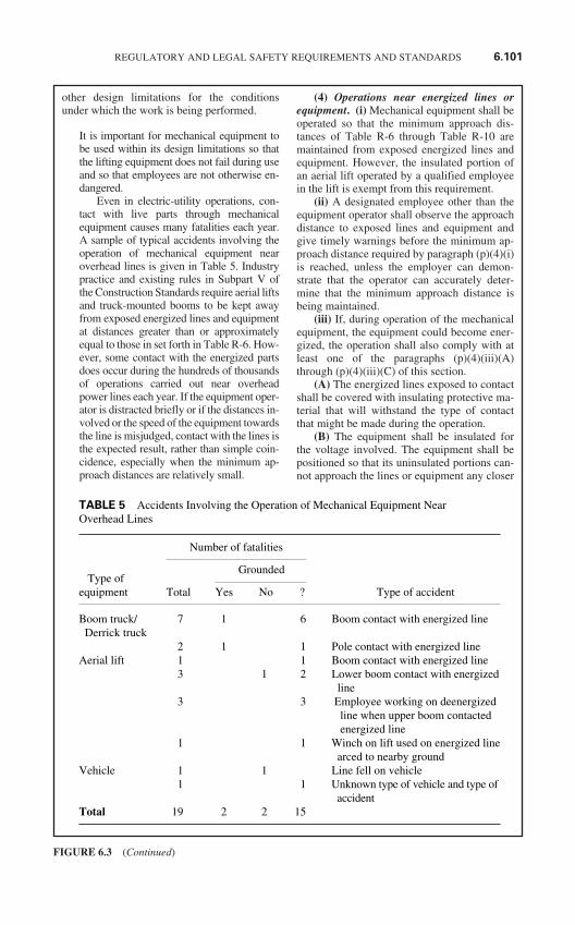
other design limitations for the conditionsunder which the work is being performed.
It is important for mechanical equipment tobe used within its design limitations so thatthe lifting equipment does not fail during useand so that employees are not otherwise en-dangered.
Even in electric-utility operations, con-tact with live parts through mechanicalequipment causes many fatalities each year.A sample of typical accidents involving theoperation of mechanical equipment nearoverhead lines is given in Table 5. Industrypractice and existing rules in Subpart V ofthe Construction Standards require aerial liftsand truck-mounted booms to be kept awayfrom exposed energized lines and equipmentat distances greater than or approximatelyequal to those in set forth in Table R-6. How-ever, some contact with the energized partsdoes occur during the hundreds of thousandsof operations carried out near overheadpower lines each year. If the equipment oper-ator is distracted briefly or if the distances in-volved or the speed of the equipment towardsthe line is misjudged, contact with the lines isthe expected result, rather than simple coin-cidence, especially when the minimum ap-proach distances are relatively small.
(4) Operations near energized lines orequipment. (i) Mechanical equipment shall beoperated so that the minimum approach dis-tances of Table R-6 through Table R-10 aremaintained from exposed energized lines andequipment. However, the insulated portion ofan aerial lift operated by a qualified employeein the lift is exempt from this requirement.
(ii) A designated employee other than theequipment operator shall observe the approachdistance to exposed lines and equipment andgive timely warnings before the minimum ap-proach distance required by paragraph (p)(4)(i)is reached, unless the employer can demon-strate that the operator can accurately deter-mine that the minimum approach distance isbeing maintained.
(iii) If, during operation of the mechanicalequipment, the equipment could become ener-gized, the operation shall also comply with atleast one of the paragraphs (p)(4)(iii)(A)through (p)(4)(iii)(C) of this section.
(A) The energized lines exposed to contactshall be covered with insulating protective ma-terial that will withstand the type of contactthat might be made during the operation.
(B) The equipment shall be insulated forthe voltage involved. The equipment shall bepositioned so that its uninsulated portions can-not approach the lines or equipment any closer
REGULATORY AND LEGAL SAFETY REQUIREMENTS AND STANDARDS 6.101
FIGURE 6.3 (Continued)
TABLE 5 Accidents Involving the Operation of Mechanical Equipment Near Overhead Lines
Number of fatalities
Type ofGrounded
equipment Total Yes No ? Type of accident
Boom truck/ 7 1 6 Boom contact with energized lineDerrick truck
2 1 1 Pole contact with energized lineAerial lift 1 1 Boom contact with energized line
3 1 2 Lower boom contact with energizedline
3 3 Employee working on deenergizedline when upper boom contactedenergized line
1 1 Winch on lift used on energized linearced to nearby ground
Vehicle 1 1 Line fell on vehicle1 1 Unknown type of vehicle and type of
accidentTotal 19 2 2 15
than the minimum approach distances speci-fied in Table R-6 through Table R-10.
(C) Each employee shall be protectedfrom hazards that might arise from equipmentcontact with the energized lines. The mea-sures used shall ensure that employees willnot be exposed to hazardous differences inpotential. Unless the employer can demon-strate that the methods in use protect eachemployee from the hazards that might arise ifthe equipment contacts the energized line, themeasures used shall include all of the follow-ing techniques:
(1) Using the best available ground to min-imize the time the lines remain energized,
(2) Bonding equipment together to mini-mize potential differences,
(3) Providing ground mats to extend areasof equipotential, and
(4) Employing insulating protective equip-ment or barricades to guard against any re-maining hazardous potential differences.
Note: Appendix C to this section containsinformation on hazardous step and touch poten-tials and on methods of protecting employeesfrom hazards resulting from such potentials.
(q) Overhead lines. This paragraph providesadditional requirements for work performed onor near overhead lines and equipment.
(1) General. (i) Before elevated structures,such as poles or towers, are subjected to suchstresses as climbing or the installation or re-moval of equipment may impose, the employershall ascertain that the structures are capable ofsustaining the additional or unbalancedstresses. If the pole or other structure cannotwithstand the loads which will be imposed, itshall be braced or otherwise supported so as toprevent failure.
Note: Appendix D to this section containstest methods that can be used in ascertainingwhether a wood pole is capable of sustainingthe forces that would be imposed by an em-ployee climbing the pole. This paragraph alsorequires the employer to ascertain that the polecan sustain all other forces that will be imposedby the work to be performed.
Paragraph (q)(1)(i) requires the employer todetermine that elevated structures such aspoles and towers are of adequate strength towithstand the stresses which will be im-posed by the work to be performed. For ex-ample, if the work involves removing andreinstalling an existing line on a utility pole,the pole will be subjected to the weight of
the employee (a vertical force) and to the re-lease and replacement of the force imposedby the overhead line (a vertical and possiblya horizontal force). The additional stress in-volved may cause the pole to break, particu-larly if the pole has rotted at its base. If thepole or structure cannot withstand the loadsto be imposed, it must be reinforced so thatfailure does not occur. This rule protects em-ployees from falling to the ground upon fail-ure of the pole or other elevated structure.
As the last step in ascertaining whether awood pole is safe to climb, as required underparagraph (q)(1)(i), checking the actual con-dition of the pole is important because of thepossibility of decay and other conditions ad-versely affecting the strength of the pole.
OSHA realizes that the employee at theworksite will be the one to inspect the struc-ture for deterioration and will also determinewhether it is safe to climb. However, underthe OSH Act, it is the employer’s responsi-bility to ensure that this is accomplished, re-gardless of who performs the work. (See thediscussion of this issue under the summaryand explanation of the introductory text ofparagraph (c), earlier in the preamble.) Addi-tionally, some work involves changing theloading on the structure. For example, re-placement transformers may be heavier, andthe equipment needed to perform the workwill impose extra stress on the pole. The em-ployee in the field is not necessarily skilled instructural engineering, and a determinationas to whether or not the pole could withstandthe stresses involved would need to be per-formed by the employer’s engineering staff.
(ii) When poles are set, moved, or removednear exposed energized overhead conductors,the pole may not contact the conductors.
(iii) When a pole is set, moved, or removednear an exposed energized overhead conductor,the employer shall ensure that each employeewears electrical protective equipment or uses in-sulated devices when handling the pole and thatno employee contacts the pole with uninsulatedparts of his or her body.
Poles are often conductive. They can bemade of metal or concrete, which OSHAconsiders to be conductive, as well as wood.Even wood poles pose an electric shock haz-ard when being moved near electric powerlines. Wet poles and poles with ground wiresrunning along their length are both highlyconductive. Some of the accidents described
6.102 CHAPTER SIX
FIGURE 6.3 (Continued)
in the record involve wood poles with in-stalled ground wires being placed betweenenergized conductors. Even though the volt-age was greater than 600 volts or was un-specified, these accidents show the dangers,regardless of the voltage involved. (Anyvoltage greater than 50 volts is normally con-sidered lethal.)
(iv) To protect employees from falling intoholes into which poles are to be placed, the holesshall be attended by employees or physicallyguarded whenever anyone is working nearby.
(2) Installing and removing overheadlines. The following provisions apply to theinstallation and removal of overhead conduc-tors or cable.
(i) The employer shall use the tension string-ing method, barriers, or other equivalent mea-sures to minimize the possibility that conductorsand cables being installed or removed will con-tact energized power lines or equipment.
Common methods of accomplishing this in-clude the use of the following techniques:stringing conductors by means of the tensionstringing method (which keeps the conduc-tors off the ground and clear of energized cir-cuits) and the use of rope nets and guards(which physically prevent one line from con-tacting another). These precautions, or equiv-alent measures, are necessary to protectemployees against electric shock and againstthe effects of equipment damage resultingfrom accidental contact of the line being in-stalled with energized parts.
(ii) The protective measures required by para-graph (p)(4)(iii) of this section for mechanicalequipment shall also be provided for conductors,cables, and pulling and tensioning equipmentwhen the conductor or cable is being installed orremoved close enough to energized conductorsthat any of the following failures could energizethe pulling or tensioning equipment or the wire orcable being installed or removed:
(A) Failure of the pulling or tensioningequipment,
(B) Failure of the wire or cable beingpulled, or
(C) Failure of the previously installed linesor equipment.
(iii) If the conductors being installed or re-moved cross over energized conductors in ex-cess of 600 volts and if the design of thecircuit-interrupting devices protecting the linesso permits, the automatic-reclosing feature ofthese devices shall be made inoperative.
(iv) Before lines are installed parallel to ex-isting energized lines, the employer shall makea determination of the approximate voltage tobe induced in the new lines, or work shall pro-ceed on the assumption that the induced volt-age is hazardous. Unless the employer candemonstrate that the lines being installed arenot subject to the induction of a hazardous volt-age or unless the lines are treated as energized,the following requirements also apply:
(A) Each bare conductor shall be grounded inincrements so that no point along the conductoris more than 2 miles (3.22 km) from a ground.
(B) The grounds required in paragraph(q)(2)(iv)(A) of this section shall be left inplace until the conductor installation is com-pleted between dead ends.
(C) The grounds required in paragraph(q)(2)(iv)(A) of this section shall be removedas the last phase of aerial cleanup.
(D) If employees are working on bare con-ductors, grounds shall also be installed at eachlocation where these employees are working,and grounds shall be installed at all open dead-end or catch-off points or the next adjacentstructure.
(E) If two bare conductors are to be spliced,the conductors shall be bonded and groundedbefore being spliced.
The standard does not provide guidelines fordetermining whether or not a hazard existsdue to induced voltage. The hazard dependsnot only on the voltage of the existing line,but also on the length of the line being in-stalled and the distance between the existingline and the new one. Electric shock from in-duced voltage poses two different hazards.First, the electric shock could cause an invol-untary reaction, which could cause a fall orother injury. Second, the electric shock itselfcould cause respiratory or cardiac arrest. If noprecautions are taken to protect employeesfrom hazards associated with involuntary re-actions from electric shock, a hazard is pre-sumed to exist if the induced voltage issufficient to pass a current of 1 milliamperethrough a 500 ohm resistor. (The 500 ohm re-sistor represents the resistance of an em-ployee. The 1 milliampere current is thethreshold of perception.) If employees areprotected from injury due to involuntary reac-tions from electric shock, a hazard is pre-sumed to exist if the resultant current wouldbe more than 6 milliamperes (the let-gothreshold for women). It is up to the employerto ensure that employees are protected against
REGULATORY AND LEGAL SAFETY REQUIREMENTS AND STANDARDS 6.103
FIGURE 6.3 (Continued)
serious injury from any voltages induced onlines being installed and to determine whetherthe voltages are high enough to warrant theadoption of the additional provisions ongrounding spelled out in paragraphs (q)(2)(iv)(A) through (q)(2)(iv)(E).
(v) Reel handling equipment, includingpulling and tensioning devices, shall be in safeoperating condition and shall be leveled andaligned.
Proper alignment of the stringing machineswill help prevent failure of the equipment,conductors, and supporting structures, whichcould result in injury to workers.
(vi) Load ratings of stringing lines, pullinglines, conductor grips, load-bearing hardwareand accessories, rigging, and hoists may not beexceeded.
(vii) Pulling lines and accessories shall berepaired or replaced when defective.
(viii) Conductor grips may not be used onwire rope, unless the grip is specifically de-signed for this application.
Equipment that has been damaged beyondmanufacturing specifications or that hasbeen damaged to the extent that its load rat-ings would be reduced are considered to bedefective. Load limits and design specifica-tions are normally provided by the manu-facturer, but they can also be found inengineering and materials handbooks.
(ix) Reliable communications, throughtwo-way radios or other equivalent means,shall be maintained between the reel tender andthe pulling rig operator.
When the tension stringing method is used,the pulling rig (which takes up the pullingrope and thereby pulls the conductors intoplace) is separated from the reel stands andtensioner (which pay out the conductors andapply tension to them) by one or more spans(the distance between the structures sup-porting the conductors). In an emergency,the pulling equipment operator may have toshut down the operation. Paragraph (q)(2)(ix)requires communication to be maintainedbetween the reel tender and the pulling rigoperator, so that in case of emergency at theconductor supply end, the pulling rig opera-tor can shut the equipment down before in-jury-causing damage occurs.
(x) The pulling rig may only be operatedwhen it is safe to do so.
Note: Examples of unsafe conditions in-clude employees in locations prohibited byparagraph (q)(2)(xi) of this section, conductorand pulling line hang-ups, and slipping of theconductor grip.
(xi) While the conductor or pulling line isbeing pulled (in motion) with a power-drivendevice, employees are not permitted directlyunder overhead operations or on the cross arm,except as necessary to guide the stringing sockor board over or through the stringing sheave.
(3) Live-line bare-hand work. In additionto other applicable provisions contained in thissection, the following requirements apply tolive-line bare-hand work:
Under certain conditions, work must be per-formed on transmission and distributionlines while they remain energized. Some-times, this work is accomplished using rub-ber insulating equipment or live-line tools.However, this equipment has voltage andother limitations which make it impossibleto insulate the employee performing workon live lines under all conditions. In suchcases, usually on medium- and high-voltagetransmission lines, the work is performedusing the live-line bare-hand technique. Ifwork is to be performed “bare-handed”, theemployee works from an insulated aerialplatform and is electrically bonded to theenergized line. Since there is essentially nopotential difference across the worker’sbody, he or she is protected from electricshock.
(i) Before using or supervising the use ofthe live-line bare-hand technique on energizedcircuits, employees shall be trained in the tech-nique and in the safety requirements of para-graph (q)(3) of this section. Employees shallreceive refresher training as required by para-graph (a)(2) of this section.
(ii) Before any employee uses the live-linebare-hand technique on energized high-voltageconductors or parts, the following informationshall be ascertained:
(A) The nominal voltage rating of the cir-cuit on which the work is to be performed,
(B) The minimum approach distances toground of lines and other energized parts onwhich work is to be performed, and
(C) The voltage limitations of equipment tobe used.
(iii) The insulated equipment, insulatedtools, and aerial devices and platforms used shallbe designed, tested, and intended for live-line
6.104 CHAPTER SIX
FIGURE 6.3 (Continued)
bare-hand work. Tools and equipment shall bekept clean and dry while they are in use.
(iv) The automatic-reclosing feature of cir-cuit-interrupting devices protecting the linesshall be made inoperative, if the design of thedevices permits.
(v) Work may not be performed when ad-verse weather conditions would make the workhazardous even after the work practices requiredby this section are employed. Additionally, workmay not be performed when winds reduce thephase-to-phase or phase-to-ground minimum ap-proach distances at the work location below thatspecified in paragraph (q)(3)(xiii) of this section,unless the grounded objects and other lines andequipment are covered by insulating guards.
Note: Thunderstorms in the immediatevicinity, high winds, snow storms, and ice stormsare examples of adverse weather conditions thatare presumed to make live-line bare-hand worktoo hazardous to perform safely.
(vi) A conductive bucket liner or other con-ductive device shall be provided for bondingthe insulated aerial device to the energized lineor equipment.
(A) The employee shall be connected to thebucket liner or other conductive device by theuse of conductive shoes, leg clips, or othermeans.
(B) Where differences in potentials at theworksite pose a hazard to employees, electro-static shielding designed for the voltage beingworked shall be provided.
(vii) Before the employee contacts the en-ergized part, the conductive bucket liner orother conductive device shall be bonded to theenergized conductor by means of a positiveconnection. This connection shall remain at-tached to the energized conductor until thework on the energized circuit is completed.
(viii) Aerial lifts to be used for live-linebare-hand work shall have dual controls (lowerand upper) as follows:
(A) The upper controls shall be within easyreach of the employee in the bucket. On a two-bucket-type lift, access to the controls shall bewithin easy reach from either bucket.
(B) The lower set of controls shall be lo-cated near the base of the boom, and they shallbe so designed that they can override operationof the equipment at any time.
(ix) Lower (ground-level) lift controls maynot be operated with an employee in the lift,except in case of emergency.
(x) Before employees are elevated into thework position, all controls (ground level and
bucket) shall be checked to determine that theyare in proper working condition.
(xi) Before the boom of an aerial lift is ele-vated, the body of the truck shall be grounded,or the body of the truck shall be barricaded andtreated as energized.
(xii) A boom-current test shall be made be-fore work is started each day, each time duringthe day when higher voltage is encountered, andwhen changed conditions indicate a need for anadditional test. This test shall consist of placingthe bucket in contact with an energized sourceequal to the voltage to be encountered for a min-imum of 3 minutes. The leakage current may notexceed 1 microampere per kilovolt of nominalphase-to-ground voltage. Work from the aeriallift shall be immediately suspended upon indica-tion of a malfunction in the equipment.
(xiii) The minimum approach distancesspecified in Table-R-6 through Table R-10shall be maintained from all grounded objectsand from lines and equipment at a potential dif-ferent from that to which the live-line bare-hand equipment is bonded, unless suchgrounded objects and other lines and equip-ment are covered by insulating guards.
(xiv) While an employee is approaching,leaving, or bonding to an energized circuit, theminimum approach distances in Table R-6through Table R-10 shall be maintained betweenthe employee and any grounded parts, includingthe lower boom and portions of the truck.
(xv) While the bucket is positioned along-side an energized bushing or insulator string,the phase-to-ground minimum approach dis-tances of Table R-6 through Table R-10 shallbe maintained between all parts of the bucketand the grounded end of the bushing or insula-tor string or any other grounded surface.
(xvi) Hand lines may not be used betweenthe bucket and the boom or between the bucketand the ground. However, non-conductive-typehand lines may be used from conductor toground if not supported from the bucket. Ropesused for live-line bare-hand work may not beused for other purposes.
(xvii) Uninsulated equipment or materialmay not be passed between a pole or structureand an aerial lift while an employee workingfrom the bucket is bonded to an energized part.
(xviii) A minimum approach distance tablereflecting the minimum approach distanceslisted in Table R-6 through Table R-10 shall beprinted on a plate of durable non-conductivematerial. This table shall be mounted so as tobe visible to the operator of the boom.
REGULATORY AND LEGAL SAFETY REQUIREMENTS AND STANDARDS 6.105
FIGURE 6.3 (Continued)
(xix) A non-conductive measuring deviceshall be readily accessible to assist employeesin maintaining the required minimum approachdistance.
(4) Towers and structures. The followingrequirements apply to work performed on tow-ers or other structures which support overheadlines.
(i) The employer shall ensure that no em-ployee is under a tower or structure while workis in progress, except where the employer candemonstrate that such a working position isnecessary to assist employees working above.
(ii) Tag lines or other similar devices shallbe used to maintain control of tower sectionsbeing raised or positioned, unless the employercan demonstrate that the use of such deviceswould create a greater hazard.
(iii) The loadline may not be detached froma member or section until the load is safely se-cured.
(iv) Except during emergency restorationprocedures, work shall be discontinued when ad-verse weather conditions would make the workhazardous in spite of the work practices requiredby this section.
Note: Thunderstorms in the immediatevicinity, high winds, snow storms, and ice stormsare examples of adverse weather conditions thatare presumed to make this work too hazardous toperform, except under emergency conditions.
Some weather conditions can make workfrom towers and other overhead structuresmore hazardous than usual. For example,icy conditions may make slips and fallsmuch more likely, in fact even unavoid-able. Under such conditions, work fromtowers and other structures would gener-ally be prohibited.
(r) Line-clearance tree trimming opera-tions. This paragraph provides additional re-quirements for line-clearance tree trimmingoperations and for equipment used in these op-erations.
(1) Electrical hazards. This paragraphdoes not apply to qualified employees.
(i) Before an employee climbs, enters, orworks around any tree, a determination shall bemade of the nominal voltage of electric powerlines posing a hazard to employees. However, adetermination of the maximum nominal voltageto which an employee will be exposed may bemade instead, if all lines are considered as ener-gized at this maximum voltage.
(ii) There shall be a second line-clearancetree trimmer within normal (that is, unassisted)
voice communication under any of the follow-ing conditions:
(A) If a line-clearance tree trimmer is to ap-proach more closely than 10 feet (305 cm) anyconductor or electric apparatus energized atmore than 750 volts or
(B) If branches or limbs being removed arecloser to lines energized at more than 750 voltsthan the distances listed in Table R-6, TableR-9, and Table R-10 or
(C) If roping is necessary to removebranches or limbs from such conductors or ap-paratus.
(iii) Line-clearance tree trimmers shallmaintain the minimum approach distancesfrom energized conductors given in Table R-6,Table R-9, and Table R-10.
(iv) Branches that are contacting exposedenergized conductors or equipment or that arewithin the distances specified in Table R-6,Table R-9, and Table R-10 may be re-moved only through the use of insulatingequipment.
Note: A tool constructed of a material thatthe employer can demonstrate has insulatingqualities meeting paragraph (j)(1) of this sec-tion is considered as insulated under this para-graph if the tool is clean and dry.
(v) Ladders, platforms, and aerial devicesmay not be brought closer to an energized partthan the distances listed in. Table R-6, Table R-9, and Table R-10.
(vi) Line-clearance tree-trimming workmay not be performed when adverse weatherconditions make the work hazardous in spite ofthe work practices required by this section.Each employee performing line-clearance treetrimming work in the aftermath of a storm orunder similar emergency conditions shall betrained in the special hazards related to thistype of work.
Note: Thunderstorms in the immediatevicinity, high winds, snow storms, and icestorms are examples of adverse weather condi-tions that are presumed to make line-clearancetree trimming work too hazardous to performsafely.
(2) Brush chippers. (i) Brush chippersshall be equipped with a locking device in theignition system.
(ii) Access panels for maintenance and ad-justment of the chipper blades and associateddrive train shall be in place and secure duringoperation of the equipment.
(iii) Brush chippers not equipped with amechanical infeed system shall be equippedwith an infeed hopper of length sufficient to
6.106 CHAPTER SIX
FIGURE 6.3 (Continued)
prevent employees from contacting the bladesor knives of the machine during operation.
(iv) Trailer chippers detached from trucksshall be chocked or otherwise secured.
(v) Each employee in the immediate area ofan operating chipper feed table shall wear per-sonal protective equipment as required by Sub-part I of this Part.
(3) Sprayers and related equipment.(i) Walking and working surfaces of sprayersand related equipment shall be covered withslip-resistant material. If slipping hazards can-not be eliminated, slip-resistant footwear orhandrails and stair rails meeting the require-ments of Subpart D may be used instead ofslip-resistant material.
(ii) Equipment on which employees standto spray while the vehicle is in motion shall beequipped with guardrails around the workingarea. The guardrail shall be constructed in ac-cordance with Subpart D of this Part.
(4) Stump cutters. (i) Stump cutters shallbe equipped with enclosures or guards to pro-tect employees.
(ii) Each employee in the immediate area ofstump grinding operations (including thestump cutter operator) shall wear personal pro-tective equipment as required by Subpart I ofthis Part.
(5) Gasoline-engine power saws. Gaso-line-engine power saw operations shall meetthe requirements of 1910.266(c)(5) of this Partand the following:
(i) Each power saw weighing more than 15pounds (6.8 kilograms, service weight) that isused in trees shall be supported by a separateline, except when work is performed from anaerial lift and except during topping or remov-ing operations where no supporting limb willbe available.
(ii) Each power saw shall be equipped witha control that will return the saw to idling speedwhen released.
(iii) Each power saw shall be equipped witha clutch and shall be so adjusted that the clutchwill not engage the chain drive at idling speed.
(iv) A power saw shall be started on theground or where it is otherwise firmly supported.Drop starting of saws over 15 pounds (6.8 kg) ispermitted outside of the bucket of an aerial liftonly if the area below the lift is clear of personnel.
(v) A power saw engine may be started andoperated only when all employees other thanthe operator are clear of the saw.
(vi) A power saw may not be running whenthe saw is being carried up into a tree by anemployee.
(vii) Power saw engines shall be stoppedfor all cleaning, refueling, adjustments, and re-pairs to the saw or motor, except as the manu-facturer’s servicing procedures requireotherwise.
(6) Backpack power units for use in prun-ing and clearing. (i) While a backpack powerunit is running, no one other than the operatormay be within 10 feet (305 cm) of the cuttinghead of a brush saw.
(ii) A backpack power unit shall beequipped with a quick shutoff switch readilyaccessible to the operator.
(iii) Backpack power unit engines shall bestopped for all cleaning, refueling, adjust-ments, and repairs to the saw or motor, exceptas the manufacturer’s servicing procedures re-quire otherwise.
(7) Rope. (i) Climbing ropes shall be usedby employees working aloft in trees. Theseropes shall have a minimum diameter of 0.5inch (1.2 cm) with a minimum breakingstrength of 2300 pounds (10.2 kN). Syntheticrope shall have elasticity of not more than 7percent.
(ii) Rope shall be inspected before each useand, if unsafe (for example, because of damageor defect), may not be used.
(iii) Rope shall be stored away from cuttingedges and sharp tools. Rope contact with corro-sive chemicals, gas, and oil shall be avoided.
(iv) When stored, rope shall be coiled andpiled, or shall be suspended, so that air can cir-culate through the coils.
(v) Rope ends shall be secured to preventtheir unraveling.
(vi) Climbing rope may not be spliced toeffect repair.
(vii) A ropes that is wet, that is contami-nated to the extent that its insulating capacity isimpaired, or that is otherwise not considered tobe insulated for the voltage involved may notbe used near exposed energized lines.
(8) Fall protection. Each employee shall betied in with a climbing rope and safety saddlewhen the employee is working above theground in a tree, unless he or she is ascendinginto the tree.
(s) Communication facilities. (1) Microwavetransmission. (i) The employer shall ensurethat no employee looks into an open waveguideor antenna that is connected to an energizedmicrowave source.
(ii) If the electromagnetic radiation levelwithin an accessible area associated with mi-crowave communications systems exceeds the
REGULATORY AND LEGAL SAFETY REQUIREMENTS AND STANDARDS 6.107
FIGURE 6.3 (Continued)
radiation protection guide given in1910.97(a)(2) of this Part, the area shall beposted with the warning symbol described in1910.97(a)(3) of this Part. The lower half of thewarning symbol shall include the followingstatements or ones that the employer candemonstrate are equivalent:
Radiation in this area may exceed hazardlimitations and special precautions are required.Obtain specific instruction before entering.
(iii) When an employee works in an areawhere the electromagnetic radiation could ex-ceed the radiation protection guide, the em-ployer shall institute measures that ensure thatthe employee’s exposure is not greater thanthat permitted by that guide. Such measuresmay include administrative and engineeringcontrols and personal protective equipment.
(2) Power line carrier. Power line carrierwork, including work on equipment used forcoupling carrier current to power line conduc-tors, shall be performed in accordance with therequirements of this section pertaining to workon energized lines.
(t) Underground electrical installations. Thisparagraph provides additional requirements forwork on underground electrical installations.
(1) Access. A ladder or other climbing de-vice shall be used to enter and exit a manholeor subsurface vault exceeding 4 feet (122 cm)in depth. No employee may climb into or out ofa manhole or vault by stepping on cables orhangers.
Employees can easily be injured in thecourse of jumping into subsurface enclo-sures or in climbing on the cables and hang-ers which have been installed in theseenclosures, the standard requires the use ofappropriate devices for employees enteringand exiting manholes and vaults. The prac-tice of climbing on equipment such as cablesand cable hangers is specifically prohibited.
(2) Lowering equipment into manholes.Equipment used to lower materials and toolsinto manholes or vaults shall be capable ofsupporting the weight to be lowered and shallbe checked for defects before use. Before toolsor material are lowered into the opening for amanhole or vault, each employee working inthe manhole or vault shall be clear of the areadirectly under the opening.
(3) Attendants for manholes. (i) Whilework is being performed in a manhole contain-ing energized electric equipment, an employee
with first aid and CPR training meeting para-graph (b)(1) of this section shall be availableon the surface in the immediate vicinity to ren-der emergency assistance.
(ii) Occasionally, the employee on the sur-face may briefly enter a manhole to provide as-sistance, other than emergency.
Note 1: An attendant may also be requiredunder paragraph (e)(7) of this section. One per-son may serve to fulfill both requirements.However, attendants required under paragraph(e)(7) of this section are not permitted to enterthe manhole.
Note 2: Employees entering manholes con-taining unguarded, uninsulated energized linesor parts of electric equipment operating at 50volts or more are required to be qualified underparagraph (l)(1) of this section.
(iii) For the purpose of inspection, house-keeping, taking readings, or similar work, anemployee working alone may enter, for briefperiods of time, a manhole where energized ca-bles or equipment are in service, if the em-ployer can demonstrate that the employee willbe protected from all electrical hazards.
(iv) Reliable communications, through two-way radios or other equivalent means, shall bemaintained among all employees involved inthe job.
Because the hazards addressed by paragraph(t)(3) are primarily related to electric shock,allowing the attendant to enter the manholebriefly has no significant effect on the safetyof the employee he or she is protecting. Incase of electric shock, the attendant wouldstill be able to provide assistance.
The attendant is permitted to remainwithin the manhole only for the short periodof time necessary to assist the employee in-side the manhole with a task that one em-ployee cannot perform alone. For example,if a second employee is needed to help lift apiece of equipment into place, the attendantcould enter only for the amount of time thatis needed to accomplish this task. However,if significant portions of the job require theassistance of a second worker in the man-hole, the attendant would not be permittedto remain in the manhole for the length oftime that would be necessary, and a thirdemployee would be required.
(4) Duct rods. If duct rods are used, theyshall be installed in the direction presenting theleast hazard to employees. An employee shallbe stationed at the far end of the duct line being
6.108 CHAPTER SIX
FIGURE 6.3 (Continued)
rodded to ensure that the required minimumapproach distances are maintained.
To install cables into the underground ducts,or conduits, that will contain them, employ-ees use a series of short jointed rods or a longflexible rod inserted into the ducts. The in-sertion of these rods into the ducts is knownas “rodding.” The rods are used to thread thecable-pulling rope through the conduit.After the rods have been withdrawn and thecable-pulling ropes have been inserted, thecables can then be pulled through by me-chanical means.
(5) Multiple cables. When multiple cablesare present in a work area, the cable to beworked shall be identified by electrical means,unless its identity is obvious by reason of dis-tinctive appearance or location or by otherreadily apparent means of identification. Ca-bles other than the one being worked shall beprotected from damage.
(6) Moving cables. Energized cables thatare to be moved shall be inspected for defects.
(7) Defective cables. Where a cable in amanhole has one or more abnormalities thatcould lead to or be an indication of an impend-ing fault, the defective cable shall be deener-gized before any employee may work in themanhole, except when service load conditionsand a lack of feasible alternatives require that thecable remain energized. In that case, employeesmay enter the manhole provided they are pro-tected from the possible effects of a failure byshields or other devices that are capable of con-taining the adverse effects of a fault in the joint.
Note: Abnormalities such as oil or com-pound leaking from cable or joints, brokencable sheaths or joint sleeves, hot localized sur-face temperatures of cables or joints, or jointsthat are swollen beyond normal tolerance arepresumed to lead to or be an indication of animpending fault.
Paragraph (t)(7) requires employees to beprotected by shields capable of containingthe adverse effects of a failure. The energythat could be released in case of a fault isknown, and the energy absorbing capabilityof a shield can be obtained from the manu-facturer or can be calculated. As long as theenergy absorbing capability of the shield ex-ceeds the available fault energy, the shieldwill protect employees. Employees are re-quired to be protected, regardless of the typeof shielding device used and of how it is ap-plied. Additionally, the standard permits this
option to be used only “if the defective cableor splice cannot be de-energized due to ser-vice load conditions”.
(8) Sheath continuity. When work is per-formed on buried cable or on cable in man-holes, metallic sheath continuity shall bemaintained or the cable sheath shall be treatedas energized.
Paragraph (t)(8) requires metallic sheathcontinuity to be maintained while work isperformed on underground cables. Bond-ing across an opening in a cable’s sheathprotects employees against shock from adifference in potential between the twosides of the opening.
(u) Substations. This paragraph provides ad-ditional requirements for substations and forwork performed in them.
(1) Access and working space. Sufficientaccess and working space shall be providedand maintained about electric equipment topermit ready and safe operation and mainte-nance of such equipment.
Note: Guidelines for the dimensions of ac-cess and working space about electric equip-ment in substations are contained in AmericanNational Standard, National Electrical SafetyCode, ANSI C2-1987. Installations meetingthe ANSI provisions comply with paragraph(u)(1) of this section. An installation that doesnot conform to this ANSI standard will,nonetheless, be considered as complying withparagraph (u)(1) of this section if the employercan demonstrate that the installation providesready and safe access based on the followingevidence:
(1) That the installation conforms to theedition of ANSI C2 that was in effect at thetime the installation was made,
(2) That the configuration of the installa-tion enables employees to maintain the mini-mum approach distances required by paragraph(l)(2) of this section while they are working onexposed, energized parts, and
(3) That the precautions taken when workis performed on the installation provide protec-tion equivalent to the protection that would beprovide by access and working space meetingANSI C2-1987.
(2) Draw-out-type circuit breakers. Whendraw-out-type circuit breakers are removed or in-serted, the breaker shall be in the open position.The control circuit shall also be rendered inoper-ative, if the design of the equipment permits.
REGULATORY AND LEGAL SAFETY REQUIREMENTS AND STANDARDS 6.109
FIGURE 6.3 (Continued)
A draw-out-type circuit breaker is one inwhich the removable portion may be with-drawn from the stationary portion withoutthe necessity of unbolting connections ormounting supports.
Some circuit breaker and control devicedesigns do not incorporate a feature allow-ing the control circuit for the breaker to berendered inoperative. These provisions areintended to prevent arcing, which could in-jure employees.
(3) Substation fences. Conductive fencesaround substations shall be grounded. When asubstation fence is expanded or a section is re-moved, fence grounding continuity shall bemaintained, and bonding shall be used to pre-vent electrical discontinuity.
(4) Guarding of rooms containing electricsupply equipment. (i) Rooms and spaces inwhich electric supply lines or equipment are in-stalled shall meet the requirements of para-graphs (u)(4)(ii) through (u)(4)(v) of thissection under the following conditions:
(A) If exposed live parts operating at 50 to150 volts to ground are located within 8 feet ofthe ground or other working surface inside theroom or space,
(B) If live parts operating at 151 to 600volts and located within 8 feet of the ground orother working surface inside the room or spaceare guarded only by location, as permittedunder paragraph (u)(5)(i) of this section, or
(C) If live parts operating at more than 600volts are located within the room or space, unless:
(1) The live parts are enclosed withingrounded, metal-enclosed equipment whoseonly openings are designed so that foreign ob-jects inserted in these openings will be deflectedfrom energized parts, or
(2) The live parts are installed at a heightabove ground and any other working surfacethat provides protection at the voltage to whichthey are energized corresponding to the protec-tion provided by an 8-foot height at 50 volts.
(ii) The rooms and spaces shall be so en-closed within fences, screens, partitions, orwalls as to minimize the possibility that un-qualified persons will enter.
(iii) Signs warning unqualified persons tokeep out shall be displayed at entrances to therooms and spaces.
(iv) Entrances to rooms and spaces that arenot under the observation of an attendant shallbe kept locked.
(v) Unqualified persons may not enter therooms or spaces while the electric supply linesor equipment are energized.
(5) Guarding of energized parts. (i) Guardsshall be provided around all live parts operat-ing at more than 150 volts to ground without aninsulating covering, unless the location of thelive parts gives sufficient horizontal or verticalor a combination of these clearances to mini-mize the possibility of accidental employeecontact.
Note: Guidelines for the dimensions ofclearance distances about electric equipment insubstations are contained in American NationalStandard, National Electrical Safety Code,ANSI C2-1987. Installations meeting the ANSIprovisions comply with paragraph (u)(5)(i) ofthis section. An installation that does not con-form to this ANSI standard will, nonetheless, beconsidered as complying with paragraph(u)(5)(i) of this section if the employer candemonstrate that the installation provides suffi-cient clearance based on the following evidence:
(1) That the installation conforms to theedition of ANSI C2 that was in effect at thetime the installation was made,
(2) That each employee is isolated from en-ergized parts at the point of closest approach, and
(3) That the precautions taken when workis performed on the installation provide protec-tion equivalent to the protection that would beprovided by horizontal and vertical clearancesmeeting ANSI C2-1987.
(ii) Except for fuse replacement and othernecessary access by qualified persons, the guard-ing of energized parts within a compartment shallbe maintained during operation and maintenancefunctions to prevent accidental contact with ener-gized parts and to prevent tools or other equip-ment from being dropped on energized parts.
(iii) When guards are removed from ener-gized equipment, barriers shall be installedaround the work area to prevent employeeswho are not working on the equipment, butwho are in the area, from contacting the ex-posed live parts.
(6) Substation entry. (i) Upon entering anattended substation, each employee other thanthose regularly working in the station shall re-port his or her presence to the employee incharge in order to receive information on specialsystem conditions affecting employee safety.
(ii) The job briefing required by paragraph(c) of this section shall cover such additionalsubjects as the location of energized equipmentin or adjacent to the work area and the limits ofany de-energized work area.
(v) Power generation. This paragraph pro-vides additional requirements and related workpractices for power generating plants.
6.110 CHAPTER SIX
FIGURE 6.3 (Continued)
(1) Interlocks and other safety devices.(i) Interlocks and other safety devices shall bemaintained in a safe, operable condition.
(ii) No interlock or other safety device maybe modified to defeat its function, except fortest, repair, or adjustment of the device.
Paragraph (v)(1)(i) requires the employer tomaintain interlocks and other safety devices(such as relief valves) in a safe and operablecondition. This requirement ensures thatthese devices perform their intended func-tion of protecting workers when called uponto do so.
(2) Changing brushes. Before exciter orgenerator brushes are changed while the gen-erator is in service, the exciter or generatorfield shall be checked to determine whether aground condition exists. The brushes may notbe changed while the generator is energized ifa ground condition exists.
Sometimes the brushes on a generator or ex-citer must be replaced while the machine isin operation. This work is unusually haz-ardous, and extreme caution must be ob-served by employees performing the job. Toprotect these workers, paragraph (v)(2) con-tains requirements for replacing brusheswhile the generator is in service. Since fieldwindings and exciters are operated in an un-grounded condition, there is no voltage withrespect to ground on the brushes as long asthere is no ground fault in the circuit. So thatno voltage to ground is present while em-ployees are changing the brushes, paragraph(v)(2) requires the exciter-field circuit to bechecked to ensure that a ground conditiondoes not exist.
(3) Access and working space. Sufficientaccess and working space shall be providedand maintained about electric equipment topermit ready and safe operation and mainte-nance of such equipment.
Note: Guidelines for the dimensions of ac-cess and working space about electric equip-ment in generating stations are contained inAmerican National Standard, National Electri-cal Safety Code, ANSI C2-1987. Installationsmeeting the ANSI provisions comply with para-graph (v)(3) of this section. An installation thatdoes not conform to this ANSI standard will,nonetheless, be considered as complying withparagraph (v)(3) of this section if the employercan demonstrate that the installation providesready and safe access based on the followingevidence:
(1) That the installation conforms to theedition of ANSI C2 that was in effect at thetime the installation was made,
(2) That the configuration of the installa-tion enables employees to maintain the mini-mum approach distances required by paragraph(l)(2) of this section while they are working onexposed, energized parts, and
(3) That the precautions taken when workis performed on the installation provide protec-tion equivalent to the protection that would beprovide by access and working space meetingANSI C2-1987.
(4) Guarding of rooms containing electricsupply equipment. (i) Rooms and spaces inwhich electric supply lines or equipment are in-stalled shall meet the requirements of para-graphs (v)(4)(ii) through (v)(4)(v) of thissection under the following conditions:
(A) If exposed live parts operating at 50 to150 volts to ground are located within 8 feet ofthe ground or other working surface inside theroom or space,
(B) If live parts operating at 151 to 600volts and located within 8 feet of the ground orother working surface inside the room or spaceare guarded only by location, as permittedunder paragraph (v)(5)(i) of this section, or
(C) If live parts operating at more than600 volts are located within the room orspace, unless:
(1) The live parts are enclosed withingrounded, metal-enclosed equipment whoseonly openings are designed so that foreign ob-jects inserted in these openings will be de-flected from energized parts, or
(2) The live parts are installed at a heightabove ground and any other working surfacethat provides protection at the voltage to whichthey are energized corresponding to the protec-tion provided by an 8-foot height at 50 volts.
(ii) The rooms and spaces shall be so en-closed within fences, screens, partitions, orwalls as to minimize the possibility that un-qualified persons will enter.
(iii) Signs warning unqualified persons tokeep out shall be displayed at entrances to therooms and spaces.
(iv) Entrances to rooms and spaces that arenot under the observation of an attendant shallbe kept locked.
(v) Unqualified persons may not enter therooms or spaces while the electric supply linesor equipment are energized.
(5) Guarding of energized parts. (i) Guardsshall be provided around all live parts operat-ing at more than 150 volts to ground without an
REGULATORY AND LEGAL SAFETY REQUIREMENTS AND STANDARDS 6.111
FIGURE 6.3 (Continued)
insulating covering, unless the location of thelive parts gives sufficient horizontal or verticalor a combination of these clearances to mini-mize the possibility of accidental employeecontact.
Note: Guidelines for the dimensions ofclearance distances about electric equipment ingenerating stations are contained in AmericanNational Standard National Electrical SafetyCode, ANSI C2-1987. Installations meetingthe ANSI provisions comply with paragraph(v)(5)(i) of this section. An installation thatdoes not conform to this ANSI standard will,nonetheless, be considered as complying withparagraph (v)(5)(i) of this section if the em-ployer can demonstrate that the installationprovides sufficient clearance based on the fol-lowing evidence:
(1) That the installation conforms to theedition of ANSI C2 that was in effect at thetime the installation was made,
(2) That each employee is isolated from en-ergized parts at the point of closest approach,and
(3) That the precautions taken when workis performed on the installation provide protec-tion equivalent to the protection that would beprovided by horizontal and vertical clearancesmeeting ANSI C2-1987.
(ii) Except for fuse replacement or other nec-essary access by qualified persons, the guardingof energized parts within a compartment shall bemaintained during operation and maintenancefunctions to prevent accidental contact with ener-gized parts and to prevent tools or other equip-ment from being dropped on energized parts.
(iii) When guards are removed from ener-gized equipment, barriers shall be installedaround the work area to prevent employees whoare not working on the equipment, but who are inthe area, from contacting the exposed live parts.
(6) Water or steam spaces. The followingrequirements apply to work in water and steamspaces associated with boilers:
(i) A designated employee shall inspect con-ditions before work is permitted and after its com-pletion. Eye protection, or full face protection ifnecessary, shall be worn at all times when con-denser, heater, or boiler tubes are being cleaned.
(ii) Where it is necessary for employees towork near tube ends during cleaning, shieldingshall be installed at the tube ends.
(7) Chemical cleaning of boilers andpressure vessels. The following requirementsapply to chemical cleaning of boilers and pres-sure vessels:
(i) Areas where chemical cleaning is inprogress shall be cordoned off to restrict accessduring cleaning. If flammable liquids, gases, orvapors or combustible materials will be used ormight be produced during the cleaning process,the following requirements also apply:
(A) The area shall be posted with signs re-stricting entry and warning of the hazards offire and explosion; and
(B) Smoking, welding, and other possibleignition sources are prohibited in these re-stricted areas.
(ii) The number of personnel in the re-stricted area shall be limited to those necessaryto accomplish the task safely.
(iii) There shall be ready access to water orshowers for emergency use.
Note: See 1910.141 of this Part for require-ments that apply to the water supply and towashing facilities.
(iv) Employees in restricted areas shallwear protective equipment meeting the re-quirements of Subpart I of this Part and includ-ing, but not limited to, protective clothing,boots, goggles, and gloves.
(8) Chlorine systems. (i) Chlorine systemenclosures shall be posted with signs restrictingentry and warning of the hazard to health andthe hazards of fire and explosion.
Note: See Subpart Z of this Part for re-quirements necessary to protect the health ofemployees from the effects of chlorine.
(ii) Only designated employees may enterthe restricted area. Additionally, the number ofpersonnel shall be limited to those necessary toaccomplish the task safely.
(iii) Emergency repair kits shall be avail-able near the shelter or enclosure to allow forthe prompt repair of leaks in chlorine lines,equipment, or containers.
(iv) Before repair procedures are started,chlorine tanks, pipes, and equipment shall bepurged with dry air and isolated from othersources of chlorine.
(v) The employer shall ensure that chlorineis not mixed with materials that would reactwith the chlorine in a dangerously exothermicor other hazardous manner.
(9) Boilers. (i) Before internal furnace orash hopper repair work is started, overheadareas shall be inspected for possible falling ob-jects. If the hazard of falling objects exists,overhead protection such as planking or netsshall be provided.
(ii) When opening an operating boiler door,employees shall stand clear of the opening of
6.112 CHAPTER SIX
FIGURE 6.3 (Continued)
the door to avoid the heat blast and gases whichmay escape from the boiler.
(10) Turbine generators. (i) Smoking andother ignition sources are prohibited near hy-drogen or hydrogen sealing systems, and signswarning of the danger of explosion and fireshall be posted.
(ii) Excessive hydrogen makeup or abnormalloss of pressure shall be considered as an emer-gency and shall be corrected immediately.
(iii) A sufficient quantity of inert gas shallbe available to purge the hydrogen from thelargest generator.
(11) Coal and ash handling. (i) Only desig-nated persons may operate railroad equipment.
(ii) Before a locomotive or locomotivecrane is moved, a warning shall be given to em-ployees in the area.
(iii) Employees engaged in switching ordumping cars may not use their feet to line updrawheads.
(iv) Drawheads and knuckles may not beshifted while locomotives or cars are in motion.
(v) When a railroad car is stopped for un-loading, the car shall be secured from displace-ment that could endanger employees.
(vi) An emergency means of stoppingdump operations shall be provided at railcardumps.
(vii) The employer shall ensure that em-ployees who work in coal- or ash-handlingconveyor areas are trained and knowledgeablein conveyor operation and in the requirementsof paragraphs (v)(11)(viii) through (v)(11)(xii)of this section.
(viii) Employees may not ride a coal- or ash-handling conveyor belt at any time. Employeesmay not cross over the conveyor belt, except atwalkways, unless the conveyor’s energy sourcehas been deenergized and has been locked out ortagged in accordance with paragraph (d) of thissection.
(ix) A conveyor that could cause injurywhen started may not be started until personnelin the area are alerted by a signal or by a desig-nated person that the conveyor is about to start.
(x) If a conveyor that could cause injury whenstarted is automatically controlled or is controlledfrom a remote location, an audible device shall beprovided that sounds an alarm that will be recog-nized by each employee as a warning that theconveyor will start and that can be clearly heard atall points along the conveyor where personnelmay be present. The warning device shall be ac-tuated by the device starting the conveyor andshall continue for a period of time before the
conveyor starts that is long enough to allow em-ployees to move clear of the conveyor system. Avisual warning may be used in place of the audi-ble device if the employer can demonstrate that itwill provide an equally effective warning in theparticular circumstances involved.
Exception: If the employer can demonstratethat the system’s function would be seriouslyhindered by the required time delay, warningsigns may be provided in place of the audiblewarning device. If the system was installed be-fore January 31, 1995, warning signs may beprovided in place of the audible warning deviceuntil such time as the conveyor or its control sys-tem is rebuilt or rewired. These warning signsshall be clear, concise, and legible and shall indi-cate that conveyors and allied equipment may bestarted at any time, that danger exists, and thatpersonnel must keep clear. These warning signsshall be provided along the conveyor at areas notguarded by position or location.
(xi) Remotely and automatically controlledconveyors, and conveyors that have operatingstations which are not manned or which are be-yond voice and visual contact from drive areas,loading areas, transfer points, and other loca-tions on the conveyor path not guarded by lo-cation, position, or guards shall be furnishedwith emergency stop buttons, pull cords, limitswitches, or similar emergency stop devices.However, if the employer can demonstrate thatthe design, function, and operation of the con-veyor do not expose an employee to hazards,an emergency stop device is not required.
(A) Emergency stop devices shall be easilyidentifiable in the immediate vicinity of suchlocations.
(B) An emergency stop device shall act di-rectly on the control of the conveyor involvedand may not depend on the stopping of anyother equipment.
(C) Emergency stop devices shall be in-stalled so that they cannot be overridden fromother locations.
(xii) Where coal-handling operations mayproduce a combustible atmosphere from fuelsources or from flammable gases or dust,sources of ignition shall be eliminated or safelycontrolled to prevent ignition of the combustibleatmosphere.
Note: Locations that are hazardous becauseof the presence of combustible dust are classifiedas Class II hazardous locations. See 1910.307 ofthis Part.
(xiii) An employee may not work on or be-neath overhanging coal in coal bunkers, coal
REGULATORY AND LEGAL SAFETY REQUIREMENTS AND STANDARDS 6.113
FIGURE 6.3 (Continued)
silos, or coal storage areas, unless the em-ployee is protected from all hazards posed byshifting coal.
(xiv) An employee entering a bunker or siloto dislodge the contents shall wear a body har-ness with lifeline attached. The lifeline shall besecured to a fixed support outside the bunkerand shall be attended at all times by an em-ployee located outside the bunker or facility.
(12) Hydroplants and equipment. Em-ployees working on or close to water gates,valves, intakes, forebays, flumes, or other loca-tions where increased or decreased water flowor levels may pose a significant hazard shall bewarned and shall vacate such dangerous areasbefore water flow changes are made.
(w) Special conditions. (1) Capacitors.The following additional requirements apply towork on capacitors and on lines connected tocapacitors.
Note: See paragraphs (m) and (n) of this sec-tion for requirements pertaining to the deenergiz-ing and grounding of capacitor installations.
(i) Before employees work on capacitors, thecapacitors shall be disconnected from energizedsources and, after a wait of at least 5 minutesfrom the time of disconnection, short-circuited.
(ii) Before the units are handled, each unitin series-parallel capacitor banks shall be short-circuited between all terminals and the capaci-tor case or its rack. If the cases of capacitors areon ungrounded substation racks, the racks shallbe bonded to ground.
(iii) Any line to which capacitors are con-nected shall be short-circuited before it is con-sidered deenergized.
Since capacitors store electric charge andcan release electrical energy even when dis-connected from their sources of supply,some precautions may be necessary, in addi-tion to those contained in §1910.269(m)(deenergizing lines and equipment) and§1910.269(n) (grounding), when work isperformed on capacitors or on lines whichare connected to capacitors. Paragraph(w)(1) sets forth precautions which will en-able this equipment to be considered asdeenergized. Under paragraph (w)(1)(i), ca-pacitors on which work is to be performedmust be disconnected from their sources ofsupply and short-circuited. This not only re-moves the sources of electric current but re-lieves the capacitors of their charge as well.
For work on individual capacitors in aseries-parallel capacitor bank, each unit mustbe short-circuited between its terminals and
the capacitor tank or rack; otherwise, indi-vidual capacitors could retain a charge.
(2) Current transformer secondaries.The secondary of a current transformer maynot be opened while the transformer is ener-gized. If the primary of the current transformercannot be deenergized before work is per-formed on an instrument, a relay, or other sec-tion of a current transformer secondary circuit,the circuit shall be bridged so that the currenttransformer secondary will not be opened.
Although the magnetic flux density in thecore of a current transformer is usually verylow, resulting in a low secondary voltage, itwill rise to saturation if the secondary circuitis opened while the transformer primary isenergized. If this occurs, the magnetic fluxwill induce a voltage in the secondary wind-ing high enough to be hazardous to the insu-lation in the secondary circuit and topersonnel. Because of this hazard to workers,paragraph (w)(2) prohibits the opening of thesecondary circuit of a current transformerwhile the primary is energized.
(3) Series streetlighting. (i) If the open-circuit voltage exceeds 600 volts, the seriesstreetlighting circuit shall be worked in accor-dance with paragraph (q) or (t) of this section,as appropriate.
(ii) A series loop may only be opened afterthe streetlighting transformer has been deener-gized and isolated from the source of supply orafter the loop is bridged to avoid an open-circuitcondition.
In a series streetlighting circuit, the lampsare connected in series, and the same cur-rent flows in each lamp. This current is sup-plied by a constant-current transformer,which provides a constant current at a vari-able voltage from a source of constant volt-age and variable current. Like the currenttransformer, the constant current source at-tempts to supply current even when the sec-ondary circuit is open. The resultantopen-circuit voltage can be very high andhazardous to employees.
(4) Illumination. Sufficient illuminationshall be provided to enable the employee toperform the work safely.
Frequently, electric power generation, trans-mission, and distribution employees mustwork at night or in enclosed places, such asmanholes, that are not illuminated by the
6.114 CHAPTER SIX
FIGURE 6.3 (Continued)
sun. Since inadvertent contact with liveparts can be fatal, good lighting is impor-tant to the safety of these workers.
(5) Protection against drowning. (i) When-ever an employee may be pulled or pushed ormay fall into water where the danger of drown-ing exists, the employee shall be provided withand shall use U.S. Coast Guard approved per-sonal flotation devices.
(ii) Each personal flotation device shall bemaintained in safe condition and shall be in-spected frequently enough to ensure that it doesnot have rot, mildew, water saturation, or anyother condition that could render the device un-suitable for use.
(iii) An employee may cross streams orother bodies of water only if a safe means ofpassage, such as a bridge, is provided.
(6) Employee protection in public workareas. (i) Traffic control signs and traffic con-trol devices used for the protection of employ-ees shall meet the requirements of 1926.200(g)(2) of this Chapter.
(ii) Before work is begun in the vicinity ofvehicular or pedestrian traffic that may endan-ger employees, warning signs or flags, andother traffic control devices shall be placed inconspicuous locations to alert and channel ap-proaching traffic.
(iii) Where additional employee protectionis necessary, barricades shall be used.
(iv) Excavated areas shall be protected withbarricades.
(v) At night, warning lights shall be promi-nently displayed.
(7) Backfeed. If there is a possibility of volt-age backfeed from sources of cogeneration orfrom the secondary system (for example, back-feed from more than one energized phase feedinga common load), the requirements of paragraph(l) of this section apply if the lines or equipmentare to be worked as energized, and the require-ments of paragraphs (m) and (n) of this sectionapply if the lines or equipment are to be workedas deenergized.
(8) Lasers. Laser equipment shall be in-stalled, adjusted, and operated in accordancewith 1926.54 of this Chapter.
(9) Hydraulic fluids. Hydraulic fluids usedfor the insulated sections of equipment shall pro-vide insulation for the voltage involved.
(x) Definitions.Affected employee. An employee whose job
requires him or her to operate or use a machine orequipment on which servicing or maintenance isbeing performed under lockout/tagout, or whose
job requires him or her to work in an area inwhich such servicing or maintenance is beingperformed.
Attendant. An employee assigned to re-main immediately outside the entrance to anenclosed or other space to render assistance asneeded to employees inside the space.
Authorized employee. An employee wholocks out or tags out machines or equipment inorder to perform servicing or maintenance on thatmachine or equipment. An affected employee be-comes an authorized employee when that em-ployee’s duties include performing servicing ormaintenance covered under this section.
Automatic circuit recloser. A self-con-trolled device for interrupting and reclosing analternating current circuit with a predeter-mined sequence of opening and reclosing fol-lowed by resetting, hold-closed, or lockoutoperation.
Barricade. A physical obstruction such astapes, cones, or A-frame type wood or metalstructures intended to provide a warning aboutand to limit access to a hazardous area.
Barrier. A physical obstruction which isintended to prevent contact with energizedlines or equipment or to prevent unauthorizedaccess to a work area.
Bond. The electrical interconnection ofconductive parts designed to maintain a com-mon electrical potential.
Bus. A conductor or a group of conductorsthat serve as a common connection for two ormore circuits.
Bushing. An insulating structure, includ-ing a through conductor or providing a pas-sageway for such a conductor, with provisionfor mounting on a barrier, conducting or other-wise, for the purposes of insulating the conduc-tor from the barrier and conducting currentfrom one side of the barrier to the other.
Cable. A conductor with insulation, or astranded conductor with or without insulationand other coverings (single-conductor cable),or a combination of conductors insulated fromone another (multiple-conductor cable).
Cable sheath. A conductive protectivecovering applied to cables.
Note: A cable sheath may consist of multi-ple layers of which one or more is conductive.
Circuit. A conductor or system of conduc-tors through which an electric current is in-tended to flow.
Clearance (for work). Authorization toperform specified work or permission to enter arestricted area.
REGULATORY AND LEGAL SAFETY REQUIREMENTS AND STANDARDS 6.115
FIGURE 6.3 (Continued)
Clearance (between objects). The cleardistance between two objects measured surfaceto surface.
Communication lines. (See Lines, com-munication.)
Conductor. A material, usually in the formof a wire, cable, or bus bar, used for carrying anelectric current.
Covered conductor. A conductor coveredwith a dielectric having no rated insulatingstrength or having a rated insulating strength lessthan the voltage of the circuit in which the con-ductor is used.
Current-carrying part. A conducting partintended to be connected in an electric circuitto a source of voltage. Non-current-carryingparts are those not intended to be so connected.
De-energized. Free from any electricalconnection to a source of potential differenceand from electric charge; not having a potentialdifferent from that of the earth.
Note: The term is used only with referenceto current-carrying parts, which are sometimesenergized (alive).
Designated employee (designated person).An employee (or person) who is designated bythe employer to perform specific duties underthe terms of this section and who is knowl-edgeable in the construction and operation ofthe equipment and the hazards involved.
Electric line truck. A truck used to trans-port personnel, tools, and material for electricsupply line work.
Electric supply equipment. Equipment thatproduces, modifies, regulates, controls, or safe-guards a supply of electric energy.
Electric supply lines. (See Lines, electricsupply.)
Electric utility. An organization responsi-ble for the installation, operation, or mainte-nance of an electric supply system.
Enclosed space. A working space, such as amanhole, vault, tunnel, or shaft that has a limitedmeans of egress or entry that is designed for pe-riodic employee entry under normal operatingconditions and that under normal conditions doesnot contain a hazardous atmosphere, but thatmay contain a hazardous atmosphere under ab-normal conditions.
Note: Spaces that are enclosed but not de-signed for employee entry under normal oper-ating conditions are not considered to beenclosed spaces for the purposes of this section.Similarly, spaces that are enclosed and that areexpected to contain a hazardous atmosphere arenot considered to be enclosed spaces for the
purposes of this section. Such spaces meet thedefinition of permit spaces in 1910.146 of thisPart, and entry into them must be performed inaccordance with that standard.
Energized (alive, live). Electrically con-nected to a source of potential difference, orelectrically charged so as to have a potentialsignificantly different from that of earth in thevicinity.
Energy isolating device. A physical devicethat prevents the transmission or release of en-ergy, including, but not limited to, the following:a manually operated electric circuit breaker, adisconnect switch, a manually operated switch, aslide gate, a slip blind, a line valve, blocks, andany similar device with a visible indication of theposition of the device. (Push buttons, selectorswitches, and other control-circuit-type devicesare not energy isolating devices.)
Energy source. Any electrical, mechani-cal, hydraulic, pneumatic, chemical, nuclear,thermal, or other energy source that couldcause injury to personnel.
Equipment (electric). A general term in-cluding material, fittings, devices, appliances,fixtures, apparatus, and the like used as part ofor in connection with an electrical installation.
Exposed. Not isolated or guarded.Ground. A conducting connection, whether
intentional or accidental, between an electric cir-cuit or equipment and the earth, or to some con-ducting body that serves in place of the earth.
Grounded. Connected to earth or to someconducting body that serves in place of the earth.
Guarded. Covered, fenced, enclosed, orotherwise protected by means of suitable coversor casings, barrier rails or screens, mats, or plat-forms, designed to minimize the possibilityunder normal conditions of dangerous approachor accidental contact by persons or objects.
Note: Wires which are insulated, but nototherwise protected are not considered asguarded.
Hazardous atmosphere means an atmos-phere that may expose employees to the risk ofdeath, incapacitation, impairment of ability toself-rescue (that is, escape unaided from an en-closed space), injury, or acute illness from oneor more of the following causes:
(1) Flammable gas, vapor, or mist in excessof 10 percent of its lower flammable limit (LFL);
(2) Airborne combustible dust at a concen-tration that meets or exceeds its LFL;
Note: This concentration may be approxi-mated as a condition in which the dust obscuresvision at a distance of 5 feet (1.52 m) or less.
6.116 CHAPTER SIX
FIGURE 6.3 (Continued)
(3) Atmospheric oxygen concentrationbelow 19.5 percent or above 23.5 percent;
(4) Atmospheric concentration of any sub-stance for which a dose or a permissible exposurelimit is published in Subpart G, OccupationalHealth and Environmental Control, or in SubpartZ, Toxic and Hazardous Substances, of this Partand which could result in employee exposure inexcess of its dose or permissible exposurelimit;
Note: An atmospheric concentration of anysubstance that is not capable of causing death,incapacitation, impairment of ability to self-rescue, injury, or acute illness due to its healtheffects is not covered by this provision.
(5) Any other atmospheric condition that isimmediately dangerous to life or health.
Note: For air contaminants for which OSHAhas not determined a dose or permissible expo-sure limit, other sources of information, such asMaterial Safety Data Sheets that comply with theHazard Communication Standard, 1910.1200 ofthis Part, published information, and internal doc-uments can provide guidance in establishing ac-ceptable atmospheric conditions.
High-power tests. Tests in which fault cur-rents, load currents, magnetizing currents, andline-dropping currents are used to test equip-ment, either at the equipment’s rated voltage orat lower voltages.
High-voltage tests. Tests in which voltagesof approximately 1000 volts are used as a prac-tical minimum and in which the voltage sourcehas sufficient energy to cause injury.
High wind. A wind of such velocity thatthe following hazards would be present:
(1) An employee would be exposed to beingblown from elevated locations, or
(2) An employee or material handlingequipment could lose control of material beinghandled, or
(3) An employee would be exposed to otherhazards not controlled by the standard in-volved.
Note: Winds exceeding 40 miles per hour(64.4 kilometers per hour) or 30 miles per hour(48.3 kilometers per hour), if material handling isinvolved, are normally considered as meeting thiscriteria unless precautions are taken to protect em-ployees from the hazardous effects of the wind.
Immediately dangerous to life or health(IDLH) means any condition that poses an im-mediate or delayed threat to life or that wouldcause irreversible adverse health effects or thatwould interfere with an individual’s ability toescape unaided from a permit space.
Note: Some materials - hydrogen fluoridegas and cadmium vapor, for example - may pro-duce immediate transient effects that, even if se-vere, may pass without medical attention, butare followed by sudden, possibly fatal collapse12-72 hours after exposure. The victim “feelsnormal” from recovery from transient effectsuntil collapse. Such materials in hazardousquantities are considered to be “immediately”dangerous to life or health.
Insulated. Separated from other conduct-ing surfaces by a dielectric (including airspace) offering a high resistance to the passageof current.
Note: When any object is said to be insu-lated, it is understood to be insulated for theconditions to which it is normally subjected.Otherwise, it is, within the purpose of this sec-tion, uninsulated.
Insulation (cable). That which is reliedupon to insulate the conductor from other con-ductors or conducting parts or from ground.
Line-clearance tree trimmer. An em-ployee who, through related training or on-the-job experience or both, is familiar with thespecial techniques and hazards involved inline-clearance tree trimming.
Note 1: An employee who is regularly as-signed to a line-clearance tree-trimming crewand who is undergoing on-the-job training andwho, in the course of such training, has demon-strated an ability to perform duties safely at hisor her level of training and who is under the di-rect supervision of a line-clearance tree trim-mer is considered to be a line-clearance treetrimmer for the performance of those duties.
Note 2: A line-clearance tree trimmer is notconsidered to be a “qualified employee” underthis section unless he or she has the training re-quired for a qualified employee under para-graph (a)(2)(ii) of this section. However, underthe electrical safety-related work practicesstandard in Subpart S of this part, a line-clear-ance tree trimmer is considered to be a “quali-fied employee”. Tree trimming performed bysuch “qualified employees” is not subject to theelectrical safety-related work practice require-ments contained in 1910.331 through 1910.335of this Part. (See also the note following1910.332(b)(3) of this Part for information re-garding the training an employee must have tobe considered a qualified employee under1910.331 through 1910.335.)
Line-clearance tree trimming. The prun-ing, trimming, repairing, maintaining, remov-ing, or clearing of trees or the cutting of brush
REGULATORY AND LEGAL SAFETY REQUIREMENTS AND STANDARDS 6.117
FIGURE 6.3 (Continued)
that is within 10 feet (305 cm) of electric sup-ply lines and equipment.
Lines. (1) Communication lines. The con-ductors and their supporting or containing struc-tures which are used for public or private signalor communication service, and which operate atpotentials not exceeding 400 volts to ground or750 volts between any two points of the circuit,and the transmitted power of which does not ex-ceed 150 watts. If the lines are operating at lessthan 150 volts, no limit is placed on the transmit-ted power of the system. Under certain condi-tions, communication cables may includecommunication circuits exceeding these limita-tions where such circuits are also used to supplypower solely to communication equipment.
Note: Telephone, telegraph, railroad sig-nal, data, clock, fire, police alarm, cable televi-sion, and other systems conforming to thisdefinition are included. Lines used for signal-ing purposes, but not included under this defin-ition, are considered as electric supply lines ofthe same voltage.
(2) Electric supply lines. Conductors usedto transmit electric energy and their necessarysupporting or containing structures. Signal linesof more than 400 volts are always supply lineswithin this section, and those of less than 400volts are considered as supply lines, if so run andoperated throughout.
Manhole. A subsurface enclosure whichpersonnel may enter and which is used for thepurpose of installing, operating, and maintain-ing submersible equipment or cable.
Manhole steps. A series of steps individu-ally attached to or set into the walls of a man-hole structure.
Minimum approach distance. The closestdistance an employee is permitted to approachan energized or a grounded object.
Qualified employee (qualified person).One knowledgeable in the construction and op-eration of the electric power generation, trans-mission, and distribution equipment involved,along with the associated hazards.
Note 1: An employee must have the train-ing required by paragraph (a)(2)(ii) of this sec-tion in order to be considered a qualifiedemployee.
Note 2: Except under paragraph (g)(2)(v)of this section, an employee who is undergoing
on-the-job training and who, in the course ofsuch training, has demonstrated an ability toperform duties safely at his or her level of train-ing and who is under the direct supervision of aqualified person is considered to be a qualifiedperson for the performance of those duties.
Step bolt. A bolt or rung attached at inter-vals along a structural member and used forfoot placement during climbing or standing.
Switch. A device for opening and closingor for changing the connection of a circuit. Inthis section, a switch is understood to be manu-ally operable, unless otherwise stated.
System operator. A qualified person desig-nated to operate the system or its parts.
Vault. An enclosure, above or belowground, which personnel may enter and whichis used for the purpose of installing, operating,or maintaining equipment or cable.
Vented vault. A vault that has provisionfor air changes using exhaust flue stacks andlow level air intakes operating on differentialsof pressure and temperature providing for air-flow which precludes a hazardous atmospherefrom developing.
Voltage. The effective (rms) potential dif-ference between any two conductors or betweena conductor and ground. Voltages are expressedin nominal values unless otherwise indicated.The nominal voltage of a system or circuit is thevalue assigned to a system or circuit of a givenvoltage class for the purpose of convenient des-ignation. The operating voltage of the systemmay vary above or below this value.
APPENDIX A TO §1910.269—FLOWCHARTS
This appendix presents information, in the formof flow charts that illustrates the scope and ap-plication of 1910.269. This appendix addressesthe interface between 1910.269 and Subpart Sof this part (electrical), between 1910.269 and1910.146 of this part (permit-required confinedspaces), and between 1910.269 and 1910.147 ofthis part [The control of hazardous energy(lockout/tagout)]. These flow charts provideguidance for employers trying to implement therequirements of 1910.269 in combination withother general industry Standards contained inPart 1910.
6.118 CHAPTER SIX
FIGURE 6.3 (Continued)
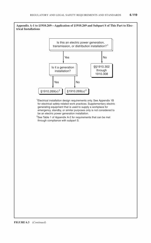
Appendix A-1 to §1910.269—Application of §1910.269 and Subpart S of This Part to Elec-trical Installations
REGULATORY AND LEGAL SAFETY REQUIREMENTS AND STANDARDS 6.119
FIGURE 6.3 (Continued)
1Electrical installation design requirements only. See Appendix 1B for electrical safety-related work practices. Supplementary electric generating equipment that is used to supply a workplace for emergency, standby, or similar purposes only is not considered to be an electric power generation installation. 2See Table 1 of Appendix A-2 for requirements that can be met through compliance with subpart S.
Is this an electric power generation,transmission, or distribution installation?1
Yes
Yes
No
No
No
§§1910.302through
1910.308
§1910.269(v)2 §1910.269(u)2
Is it a generationinstallation?
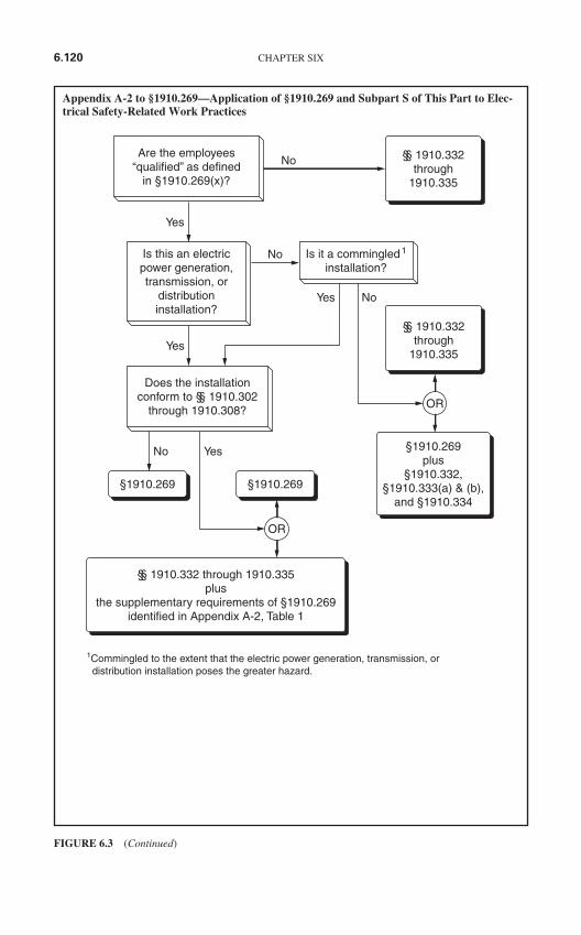
Appendix A-2 to §1910.269—Application of §1910.269 and Subpart S of This Part to Elec-trical Safety-Related Work Practices
6.120 CHAPTER SIX
FIGURE 6.3 (Continued)
1Commingled to the extent that the electric power generation, transmission, or distribution installation poses the greater hazard.
No
No
No
§§ 1910.332through
1910.335
Yes
Yes
Yes
Yes
§§ 1910.332through
1910.335
No
§1910.269 §1910.269
§1910.269plus
§1910.332,§1910.333(a) & (b),
and §1910.334
§§ 1910.332 through 1910.335plus
the supplementary requirements of §1910.269identified in Appendix A-2, Table 1
Are the employees“qualified” as defined
in §1910.269(x)?
Does the installationconform to §§ 1910.302
through 1910.308?
Is it a commingled1
installation?Is this an electricpower generation,transmission, or
distributioninstallation?
OR
OR
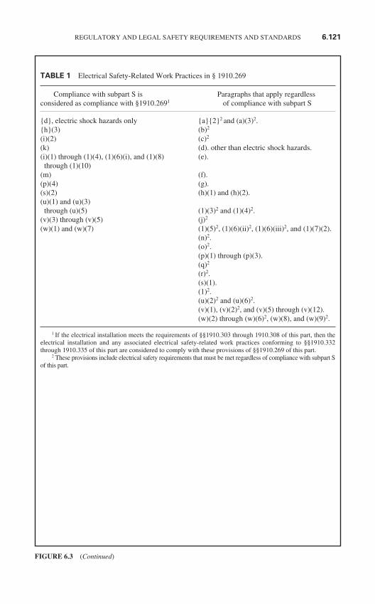
REGULATORY AND LEGAL SAFETY REQUIREMENTS AND STANDARDS 6.121
FIGURE 6.3 (Continued)
TABLE 1 Electrical Safety-Related Work Practices in § 1910.269
Compliance with subpart S is Paragraphs that apply regardlessconsidered as compliance with §1910.2691 of compliance with subpart S
d, electric shock hazards only a22 and (a)(3)2.h(3) (b)2
(i)(2) (c)2
(k) (d). other than electric shock hazards.(i)(1) through (1)(4), (1)(6)(i), and (1)(8) (e).
through (1)(10)(m) (f).(p)(4) (g).(s)(2) (h)(1) and (h)(2).(u)(1) and (u)(3)
through (u)(5) (1)(3)2 and (1)(4)2.(v)(3) through (v)(5) (j)2
(w)(1) and (w)(7) (1)(5)2, (1)(6)(ii)2, (1)(6)(iii)2, and (1)(7)(2).(n)2.(o)2.(p)(1) through (p)(3).(q)2
(r)2.(s)(1).(1)2.(u)(2)2 and (u)(6)2.(v)(1), (v)(2)2, and (v)(5) through (v)(12).(w)(2) through (w)(6)2, (w)(8), and (w)(9)2.
1 If the electrical installation meets the requirements of §§1910.303 through 1910.308 of this part, then theelectrical installation and any associated electrical safety-related work practices conforming to §§1910.332through 1910.335 of this part are considered to comply with these provisions of §§1910.269 of this part.
2 These provisions include electrical safety requirements that must be met regardless of compliance with subpart Sof this part.
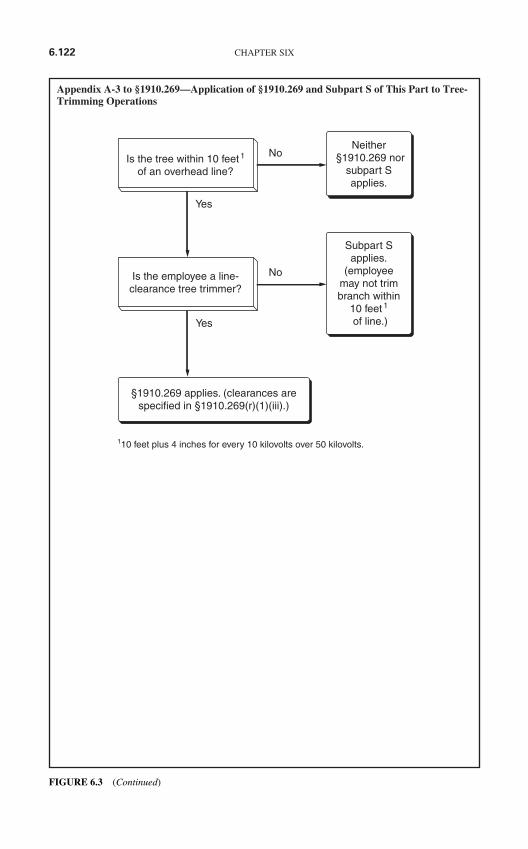
Appendix A-3 to §1910.269—Application of §1910.269 and Subpart S of This Part to Tree-Trimming Operations
6.122 CHAPTER SIX
No
No
Yes
Yes
Neither§1910.269 nor
subpart Sapplies.
Subpart Sapplies.
(employeemay not trimbranch within
10 feet1
of line.)
§1910.269 applies. (clearances arespecified in §1910.269(r)(1)(iii).)
110 feet plus 4 inches for every 10 kilovolts over 50 kilovolts.
Is the tree within 10 feet1
of an overhead line?
Is the employee a line-clearance tree trimmer?
FIGURE 6.3 (Continued)
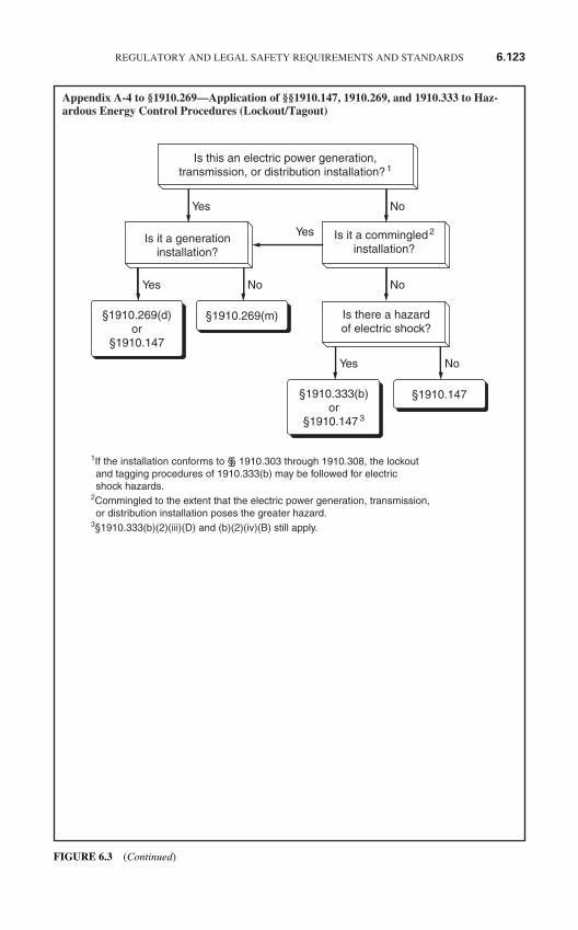
Appendix A-4 to §1910.269—Application of §§1910.147, 1910.269, and 1910.333 to Haz-ardous Energy Control Procedures (Lockout/Tagout)
REGULATORY AND LEGAL SAFETY REQUIREMENTS AND STANDARDS 6.123
Yes
Yes
Yes
Yes
No
No
No
No
§1910.269(d)or
§1910.147
§1910.269(m)
§1910.333(b)or
§1910.1473
§1910.147
1If the installation conforms to §§ 1910.303 through 1910.308, the lockout and tagging procedures of 1910.333(b) may be followed for electric shock hazards.2Commingled to the extent that the electric power generation, transmission, or distribution installation poses the greater hazard.3§1910.333(b)(2)(iii)(D) and (b)(2)(iv)(B) still apply.
Is this an electric power generation,transmission, or distribution installation?1
Is it a commingled2
installation?
Is there a hazardof electric shock?
Is it a generationinstallation?
FIGURE 6.3 (Continued)
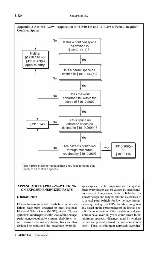
Appendix A-5 to §1910.269—Application of §§1910.146 and 1910.269 to Permit-RequiredConfined Spaces
6.124 CHAPTER SIX
No
No
No
No
No
Neither§1910.146 nor§1910.269(e)apply to entry.
Yes
Yes
Yes
Yes
Yes §1910.269(e)or
§1910.146
1See §1910.146(c) for general non-entry requirements that apply to all confined spaces.
Is this a confined spaceas defined in
§1910.146(b)?1
Is it a permit space asdefined in §1910.146(b)?
Does the workperformed fall within the
scope of §1910.269?
Is this space anenclosed space as
defined in §1910.269(x)?
Are hazards controlledthrough measures
required by §1910.269?
§1910.146
APPENDIX B TO §1910.269—WORKINGON EXPOSED ENERGIZED PARTS
I. Introduction
Electric transmission and distribution line instal-lations have been designed to meet NationalElectrical Safety Code (NESC), ANSI C2, re-quirements and to provide the level of line outageperformance required by system reliability crite-ria. Transmission and distribution lines are alsodesigned to withstand the maximum overvolt-
ages expected to be impressed on the system.Such overvoltages can be caused by such condi-tions as switching surges, faults, or lightning. In-sulator design and lengths and the clearances tostructural parts (which, for low voltage throughextra-high voltage, or EHV, facilities, are gener-ally based on the performance of the line as a re-sult of contamination of the insulation or duringstorms) have, over the years, come closer to theminimum approach distances used by workers(which are generally based on non-storm condi-tions). Thus, as minimum approach (working)
FIGURE 6.3 (Continued)
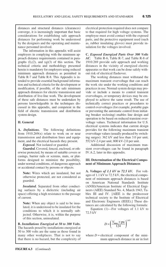
distances and structural distances (clearances)converge, it is increasingly important that basicconsiderations for establishing safe approachdistances for performing work be understoodby the designers and the operating and mainte-nance personnel involved.
The information in this appendix will assistemployers in complying with the minimum ap-proach distance requirements contained in para-graphs (l),(2), and (q)(3) of this section. Thetechnical criteria and methodology presentedherein is mandatory for employers using reducedminimum approach distances as permitted inTable R-7 and Table R-8. This Appendix is in-tended to provide essential background informa-tion and technical criteria for the development ormodification, if possible, of the safe minimumapproach distances for electric transmission anddistribution of live-line work. The developmentof these safe distances must be undertaken bypersons knowledgeable in the techniques dis-cussed in this appendix, and competent in thefield of electric transmission and distributionsystem design.
II. General
A. Definitions. The following definitionsfrom 1910.269(x) relate to work on or neartransmission and distribution lines and equip-ment, and the electrical hazards they present.
Exposed. Not isolated or guarded. Guarded. Covered, fenced, enclosed, or oth-
erwise protected, by means of suitable covers orcasings, barrier rails or screens, mats, or plat-forms designed to minimize the possibility,under normal conditions, of dangerous approachor accidental contact by persons or objects.
Note: Wires which are insulated, but nototherwise protected, are not considered asguarded.
Insulated. Separated from other conduct-ing surfaces by a dielectric (including airspace) offering a high resistance to the passageof current.
Note: When any object is said to be insu-lated, it is understood to be insulated for theconditions to which it is normally sub-jected. Otherwise, it is, within the purposeof this section, uninsulated.
B. Installations Energized at 50 to 300 Volts.The hazards posed by installations energized at50 to 300 volts are the same as those found inmany other workplaces. That is not to saythat there is no hazard, but the complexity of
electrical protection required does not compareto that required for high voltage systems. Theemployee must avoid contact with the exposedparts, and the protective equipment used (suchas, rubber insulating gloves) must provide in-sulation for the voltages involved.
C. Exposed Energized Parts Over 300 VoltsAC. Table R-6, Table R-7, and Table R-8 of1910.269 provide safe approach and workingdistances in the vicinity of energized electricapparatus so that work can be done safely with-out risk of electrical flashover.
The working distances must withstand themaximum transient overvoltage that can reachthe work site under the working conditions andpractices in use. Normal system design may pro-vide or include a means to control transientovervoltages, or temporary devices may be em-ployed to achieve the same result. The use oftechnically correct practices or procedures tocontrol overvoltages (for example, portable gapsor preventing the automatic control from initiat-ing breaker reclosing) enables line design andoperation to be based on reduced transient over-voltage values. Technical information for U.S.electrical systems indicates that current designprovides for the following maximum transientovervoltage values (usually produced by switch-ing surges): 362 kV and less than 3.0 per unit;552 kV-2.4 per unit; 800 kV-2.0 per unit.
Additional discussion of maximum tran-sient overvoltages can be found in paragraphIV.A.2, later in this appendix.
III. Determination of the Electrical Compo-nent of Minimum Approach Distances
A. Voltages of 1.1 kV to 72.5 kV. For volt-ages of 1.1 kV to 72.5 kV, the electrical compo-nent of minimum approach distances is basedon American National Standards Institute(ANSI)/American Institute of Electrical Engi-neers (AIEE) Standard No. 4, March 1943, Ta-bles III and IV. [AIEE is the predecessortechnical society to the Institute of Electricaland Electronic Engineers (IEEE).] These dis-tances are calculated by the following formula:
Equation (1)—For voltages of 1.1 kV to72.5 kV
where D = electrical component of the mini-mum approach distance in air in feet
DV
=×
max.pu
124
1 63
REGULATORY AND LEGAL SAFETY REQUIREMENTS AND STANDARDS 6.125
FIGURE 6.3 (Continued)
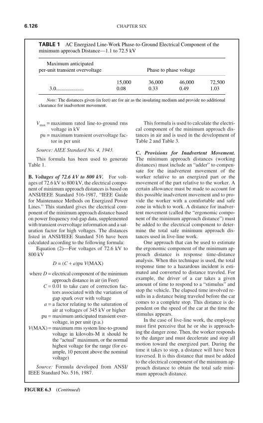
Vmax = maximum rated line-to-ground rmsvoltage in kV
pu = maximum transient overvoltage fac-tor in per unit
Source: AIEE Standard No. 4, 1943.
This formula has been used to generateTable 1.
B. Voltages of 72.6 kV to 800 kV. For volt-ages of 72.6 kV to 800 kV, the electrical compo-nent of minimum approach distances is based onANSI/IEEE Standard 516-1987, “IEEE Guidefor Maintenance Methods on Energized PowerLines.” This standard gives the electrical com-ponent of the minimum approach distance basedon power frequency rod-gap data, supplementedwith transient overvoltage information and a sat-uration factor for high voltages. The distanceslisted in ANSI/IEEE Standard 516 have beencalculated according to the following formula:
Equation (2)—For voltages of 72.6 kV to800 kV
D = (C + a)pu V(MAX)
where D = electrical component of the minimumapproach distance in air (in Feet)
C = 0.01 to take care of correction fac-tors associated with the variation ofgap spark over with voltage
a = a factor relating to the saturation ofair at voltages of 345 kV or higher
pu = maximum anticipated transient over-voltage, in per unit (p.u.)
V(MAX) = maximum rms system line-to-groundvoltage in kilovolts-M it should bethe “actual” maximum, or the normalhighest voltage for the range (for ex-ample, 10 percent above the nominalvoltage)
Source: Formula developed from ANSI/IEEE Standard No. 516, 1987.
This formula is used to calculate the electri-cal component of the minimum approach dis-tances in air and is used in the development ofTable 2 and Table 3.
C. Provisions for Inadvertent Movement.The minimum approach distances (workingdistances) must include an “adder” to compen-sate for the inadvertent movement of theworker relative to an energized part or themovement of the part relative to the worker. Acertain allowance must be made to account forthis possible inadvertent movement and to pro-vide the worker with a comfortable and safezone in which to work. A distance for inadver-tent movement (called the “ergonomic compo-nent of the minimum approach distance”) mustbe added to the electrical component to deter-mine the total safe minimum approach dis-tances used in live-line work.
One approach that can be used to estimatethe ergonomic component of the minimum ap-proach distance is response time-distanceanalysis. When this technique is used, the totalresponse time to a hazardous incident is esti-mated and converted to distance traveled. Forexample, the driver of a car takes a givenamount of time to respond to a “stimulus” andstop the vehicle. The elapsed time involved re-sults in a distance being traveled before the carcomes to a complete stop. This distance is de-pendent on the speed of the car at the time thestimulus appears.
In the case of live-line work, the employeemust first perceive that he or she is approach-ing the danger zone. Then, the worker respondsto the danger and must decelerate and stop allmotion toward the energized part. During thetime it takes to stop, a distance will have beentraversed. It is this distance that must be addedto the electrical component of the minimum ap-proach distance to obtain the total safe mini-mum approach distance.
6.126 CHAPTER SIX
TABLE 1 AC Energized Line-Work Phase-to-Ground Electrical Component of theminimum approach Distance—1.1 to 72.5 kV
Maximum anticipatedper-unit transient overvoltage Phase to phase voltage
15,000 36,000 46,000 72,5003.0..................... 0.08 0.33 0.49 1.03
Note: The distances given (in feet) are for air as the insulating medium and provide no additionalclearance for inadvertent movement.
FIGURE 6.3 (Continued)
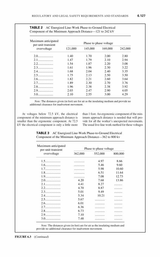
At voltages below 72.5 kV, the electricalcomponent of the minimum approach distance issmaller than the ergonomic component. At 72.5kV the electrical component is only a little more
than 1 foot. An ergonomic component of the min-imum approach distance is needed that will pro-vide for all the worker’s unexpected movements.The usual live-line work method for these voltages
REGULATORY AND LEGAL SAFETY REQUIREMENTS AND STANDARDS 6.127
TABLE 2 AC Energized Line-Work Phase-to-Ground ElectricalComponent of the Minimum Approach Distance—121 to 242 kV
Phase to phase voltage
121,000 145,000 169,000 242,000
2.0................... 1.40 1.70 2.00 2.802.1................... 1.47 1.79 2.10 2.942.2................... 1.54 1.87 2.20 3.082.3................... 1.61 1.96 2.30 3.222.4................... 1.68 2.04 2.40 3.352.5................... 1.75 2.13 2.50 3.502.6................... 1.82 2.21 2.60 3.642.7................... 1.89 2.30 2.70 3.762.8................... 1.96 2.38 2.38 3.922.9................... 2.03 2.47 2.90 4.053.0................... 2.10 2.55 3.00 4.29
Note: The distances given (in feet) are for air as the insulating medium and provide noadditional clearance for inadvertent movement.
Maximum anticipatedper-unit transient
overvoltage
TABLE 3 AC Energized Line-Work Phase-to-Ground ElectricalComponent of the Minimum Approach Distance—362 to 800 kv
Phase to phase voltage
362,000 552,000 800,000
1.5................... ............. 4.97 8.661.6................... ............. 5.46 9.601.7................... ............. 5.98 10.601.8................... ............. 6.51 11.641.9................... ............. 7.08 12.732.0................... 4.20 7.68 13.862.1................... 4.41 8.27 ..........2.2................... 4.70 8.87 ..........2.3................... 5.01 9.49 ..........2.4................... 5.34 10.21 ..........2.5................... 5.67 ............ ..........2.6................... 6.01 ............ ..........2.7................... 6.36 ............ ..........2.8................... 6.73 ............ ..........2.9................... 7.10 ............ ..........3.0................... 7.48 ............ ..........
Note: The distances given (in feet) are for air as the insulating medium andprovide no additional clearance for inadvertent movement.
Maximum anticipatedper-unit transient
overvoltage
FIGURE 6.3 (Continued)
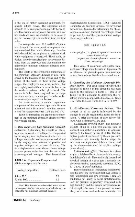
is the use of rubber insulating equipment, fre-quently rubber gloves. The energized objectneeds to be far enough away to provide the work-er’s face with a safe approach distance, as his orher hands and arms are insulated. In this case, 2feet has been accepted as a sufficient and practicalvalue.
For voltages between 72.6 and 800 kV, thereis a change in the work practices employed dur-ing energized line work. Generally, live-linetools (hot sticks) are employed to perform workwhile equipment is energized. These tools, bydesign, keep the energized part at a constant dis-tance from the employee and thus maintain theappropriate minimum approach distance auto-matically.
The length of the ergonomic component ofthe minimum approach distance is also influ-enced by the location of the worker and by thenature of the work. In these higher voltageranges, the employees use work methods thatmore tightly control their movements than whenthe workers perform rubber glove work. Theworker is farther from energized line or equip-ment and needs to be more precise in his or hermovements just to perform the work.
For these reasons, a smaller ergonomiccomponent of the minimum approach distanceis needed, and a distance of 1 foot has been se-lected for voltages between 72.6 and 800 kV.
Table 4 summarizes the ergonomic compo-nent of the minimum approach distance for thetwo voltage ranges.
D. Bare-Hand Live-Line Minimum ApproachDistances. Calculating the strength of phase-to-phase transient overvoltages is complicatedby the varying time displacement between over-voltages on parallel conductors (electrodes) andby the varying ratio between the positive andnegative voltages on the two electrodes. Thetime displacement causes the maximum voltagebetween phases to be less than the sum of thephase-to-ground voltages. The International
Electrotechnical Commission (IEC) TechnicalCommittee 28, Working Group 2, has developedthe following formula for determining the phase-to-phase maximum transient overvoltage, basedon per unit (p.u.) of the system nominal voltagephase-to-ground crest:
pu(p) = pu(g) + 1.6.
where pu(g) = p.u. phase-to-ground maximumtransient overvoltage
pu(p) = p.u. phase-to-phase maximum tran-sient overvoltage
This value of maximum anticipated tran-sient overvoltage must be used in Equation (2)to calculate the phase-to-phase minimum ap-proach distances for live-line bare-hand work.
E. Compiling the Minimum Approach Dis-tance Tables. For each voltage involved, thedistance in Table 4 in this appendix has beenadded to the distance in Table 1, Table 2, orTable 3 in this appendix to determine the re-sulting minimum approach distances in TableR-6, Table R-7, and Table R-8 in 1910.269.
F. Miscellaneous Correction Factors. Thestrength of an air gap is influenced by thechanges in the air medium that forms the insu-lation. A brief discussion of each factor fol-lows, with a summary at the end.
1. Dielectric strength of air. The dielectricstrength of air in a uniform electric field atstandard atmospheric conditions is approxi-mately 31 kV (crest) per cm at 60 Hz. The dis-ruptive gradient is affected by the air pressure,temperature, and humidity, by the shape, di-mensions, and separation of the electrodes, andby the characteristics of the applied voltage(wave shape).
2. Atmospheric effect. Flashover for a givenair gap is inhibited by an increase in the density(humidity) of the air. The empirically determinedelectrical strength of a given gap is normally ap-plicable at standard atmospheric conditions (20°C,101.3 kPa, 11 g/cm3 humidity).
The combination of temperature and air pres-sure that gives the lowest gap flashover voltage ishigh temperature and low pressure. These areconditions not likely to occur simultaneously.Low air pressure is generally associated withhigh humidity, and this causes increased electri-cal strength. An average air pressure is morelikely to be associated with low humidity. Hot
6.128 CHAPTER SIX
TABLE 4 Ergonomic Component ofMinimum Approach Distance
Voltage range (kV) Distance (feet)
1.1 to 72.5..................... 2.072.6 to 800..................... 1.0
Note: This distance must be added to the electri-cal component of the minimum approach distance toobtain the full minimum approach distance.
FIGURE 6.3 (Continued)
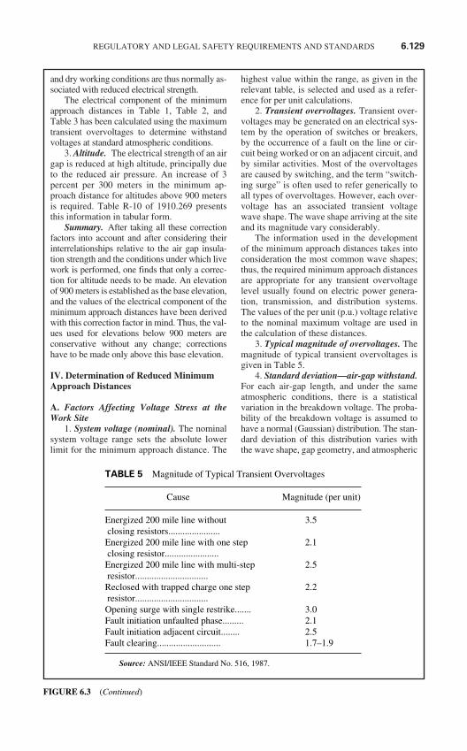
and dry working conditions are thus normally as-sociated with reduced electrical strength.
The electrical component of the minimumapproach distances in Table 1, Table 2, andTable 3 has been calculated using the maximumtransient overvoltages to determine withstandvoltages at standard atmospheric conditions.
3. Altitude. The electrical strength of an airgap is reduced at high altitude, principally dueto the reduced air pressure. An increase of 3percent per 300 meters in the minimum ap-proach distance for altitudes above 900 metersis required. Table R-10 of 1910.269 presentsthis information in tabular form.
Summary. After taking all these correctionfactors into account and after considering theirinterrelationships relative to the air gap insula-tion strength and the conditions under which livework is performed, one finds that only a correc-tion for altitude needs to be made. An elevationof 900 meters is established as the base elevation,and the values of the electrical component of theminimum approach distances have been derivedwith this correction factor in mind. Thus, the val-ues used for elevations below 900 meters areconservative without any change; correctionshave to be made only above this base elevation.
IV. Determination of Reduced MinimumApproach Distances
A. Factors Affecting Voltage Stress at theWork Site
1. System voltage (nominal). The nominalsystem voltage range sets the absolute lowerlimit for the minimum approach distance. The
highest value within the range, as given in therelevant table, is selected and used as a refer-ence for per unit calculations.
2. Transient overvoltages. Transient over-voltages may be generated on an electrical sys-tem by the operation of switches or breakers,by the occurrence of a fault on the line or cir-cuit being worked or on an adjacent circuit, andby similar activities. Most of the overvoltagesare caused by switching, and the term “switch-ing surge” is often used to refer generically toall types of overvoltages. However, each over-voltage has an associated transient voltagewave shape. The wave shape arriving at the siteand its magnitude vary considerably.
The information used in the developmentof the minimum approach distances takes intoconsideration the most common wave shapes;thus, the required minimum approach distancesare appropriate for any transient overvoltagelevel usually found on electric power genera-tion, transmission, and distribution systems.The values of the per unit (p.u.) voltage relativeto the nominal maximum voltage are used inthe calculation of these distances.
3. Typical magnitude of overvoltages. Themagnitude of typical transient overvoltages isgiven in Table 5.
4. Standard deviation—air-gap withstand.For each air-gap length, and under the sameatmospheric conditions, there is a statisticalvariation in the breakdown voltage. The proba-bility of the breakdown voltage is assumed tohave a normal (Gaussian) distribution. The stan-dard deviation of this distribution varies withthe wave shape, gap geometry, and atmospheric
REGULATORY AND LEGAL SAFETY REQUIREMENTS AND STANDARDS 6.129
TABLE 5 Magnitude of Typical Transient Overvoltages
Cause Magnitude (per unit)
Energized 200 mile line without 3.5closing resistors......................Energized 200 mile line with one step 2.1closing resistor.......................Energized 200 mile line with multi-step 2.5resistor...............................Reclosed with trapped charge one step 2.2resistor...............................Opening surge with single restrike....... 3.0Fault initiation unfaulted phase......... 2.1Fault initiation adjacent circuit........ 2.5Fault clearing........................... 1.7–1.9
Source: ANSI/IEEE Standard No. 516, 1987.
FIGURE 6.3 (Continued)
conditions. The withstand voltage of the airgap used in calculating the electrical compo-nent of the minimum approach distance hasbeen set at three standard deviations (3 sigma*)below the critical flashover voltage. (The criti-cal flashover voltage is the crest value of theimpulse wave that, under specified conditions,causes flashover on 50 percent of the applica-tions. An impulse wave of three standard devi-ations below this value, that is, the withstandvoltage, has a probability of flashover of ap-proximately 1 in 1000.)
∗Note: Sigma is the symbol for standarddeviation. http://www.osha.gov/pls/ oshaweb/1#1
5. Broken Insulators. Tests have shown thatthe insulation strength of an insulator string withbroken skirts is reduced. Broken units may havelost up to 70 percent of their withstand capacity.Because the insulating capability of a brokenunit cannot be determined without testing it,damaged units in an insulator are usually con-sidered to have no insulating value. Addition-ally, the overall insulating strength of a stringwith broken units may be further reduced in thepresence of a live-line tool alongside it. Thenumber of good units that must be present in astring is based on the maximum overvoltagepossible at the worksite.
B. Minimum Approach Distances Based onKnown Maximum Anticipated Per-Unit Tran-sient Overvoltages
1. Reduction of the minimum approach dis-tance for AC systems. When the transient over-voltage values are known and supplied by theemployer, Table R-7 and Table R-8 of 1910.269allow the minimum approach distances from en-ergized parts to be reduced. In order to determinewhat this maximum overvoltage is, the employermust undertake an engineering analysis of thesystem. As a result of this engineering study, theemployer must provide new live work proce-dures, reflecting the new minimum approach dis-tances, the conditions and limitations ofapplication of the new minimum approach dis-tances, and the specific practices to be used whenthese procedures are implemented.
2. Calculation of reduced approach dis-tance values. The following method of calcu-lating reduced minimum approach distances isbased on ANSI/IEEE Standard 516:
Step 1. Determine the maximum voltage(with respect to a given nominal voltage range)for the energized part.
Step 2. Determine the maximum transientovervoltage (normally a switching surge) thatcan be present at the work site during work op-eration.
Step 3. Determine the technique to be usedto control the maximum transient overvoltage.(See paragraphs IV.C and IV.D of this appen-dix.) Determine the maximum voltage that canexist at the work site with that form of controlin place and with a confidence level of 3 sigma.This voltage is considered to be the withstandvoltage for the purpose of calculating the ap-propriate minimum approach distance.
Step 4. Specify in detail the control tech-nique to be used, and direct its implementationduring the course of the work.
Step 5. Using the new value of transientovervoltage in per unit (p.u.), determine the re-quired phase-to-ground minimum approachdistance from Table R-7 or Table R-8 of1910.269.
C. Methods of Controlling Possible TransientOvervoltage Stress Found on a System
1. Introduction. There are several means ofcontrolling overvoltages that occur on transmis-sion systems. First, the operation of circuitbreakers or other switching devices may bemodified to reduce switching transient overvolt-ages. Second, the overvoltage itself may beforcibly held to an acceptable level by means ofinstallation of surge arresters at the specific lo-cation to be protected. Third, the transmissionsystem may be changed to minimize the effectof switching operations.
2. Operation of circuit breakers.† Themaximum transient overvoltage that can reachthe work site is often due to switching on theline on which work is being performed. If theautomatic-reclosing is removed during ener-gized line work so that the line will not bereenergized after being opened for any reason,the maximum switching surge overvoltage isthen limited to the larger of the opening surgeor the greatest possible fault-generated surge,provided that the devices (for example, inser-tion resistors) are operable and will function tolimit the transient overvoltage. It is essentialthat the operating ability of such devices be as-sured when they are employed to limit theovervoltage level. If it is prudent not to removethe reclosing feature because of system operat-ing conditions, other methods of controllingthe switching surge level may be necessary.
†Note: The detailed design of a circuit inter-rupter, such as the design of the contacts, of
6.130 CHAPTER SIX
FIGURE 6.3 (Continued)
resistor insertion, and of breaker timing con-trol, are beyond the scope of this appendix.These features are routinely provided as partof the design for the system. Only featuresthat can limit the maximum switching tran-sient overvoltage on a system are discussedin this appendix. http://www.osha.gov/pls/oshaweb/2#2
Transient surges on an adjacent line, partic-ularly for double circuit construction, maycause a significant overvoltage on the line onwhich work is being performed. The couplingto adjacent lines must be accounted for whenminimum approach distances are calculatedbased on the maximum transient overvoltage.
3. Surge arresters. The use of modern surgearresters has permitted a reduction in the basicimpulse-insulation levels of much transmissionsystem equipment. The primary function of earlyarresters was to protect the system insulationfrom the effects of lightning. Modern arrestersnot only dissipate lightning-caused transients,but may also control many other system tran-sients that may be caused by switching or faults.
It is possible to use properly designed ar-resters to control transient overvoltages along atransmission line and thereby reduce the requi-site length of the insulator string. On the otherhand, if the installation of arresters has notbeen used to reduce the length of the insulatorstring, it may be used to reduce the minimumapproach distance instead.‡
‡Note: Surge arrestor application is beyondthe scope of this appendix. However, if the ar-restor is installed near the work site, the appli-cation would be similar to protective gaps asdiscussed in paragraph IV.D. of this appen-dix. http://www.osha.gov/pls/oshaweb/3#3
4. Switching Restrictions. Another form ofovervoltage control is the establishment ofswitching restrictions, under which breakers arenot permitted to be operated until certain systemconditions are satisfied. Restriction of switchingis achieved by the use of a tagging system, simi-lar to that used for a “permit,” except that thecommon term used for this activity is a “hold-off” or “restriction.” These terms are used to in-dicate that operation is not prevented, but onlymodified during the live-work activity.
D. Minimum Approach Distance Based onControl of Voltage Stress (Overvoltages) atthe Work Site.
Reduced minimum approach distances canbe calculated as follows:
1. First Method—Determining the re-duced minimum approach distance from agiven withstand voltage.§
§Note: Since a given rod gap of a givenconfiguration corresponds to a certainwithstand voltage, this method can also beused to determine the minimum approachdistance for a known gap. http://www.osha.gov/pls/oshaweb/4#4
Step 1. Select the appropriate withstandvoltage for the protective gap based on systemrequirements and an acceptable probability ofactual gap flashover.
Step 2. Determine a gap distance that pro-vides a withstand voltage** greater than orequal to the one selected in the first step. ††
**Note: The withstand voltage for the gap isequal to 85 percent of its critical flashovervoltage. http://www.osha.gov/pls/oshaweb/5#5††Note: Switch steps 1 and 2 if the length ofthe protective gap is known. The withstandvoltage must then be checked to ensure thatit provides an acceptable probability of gapflashover. In general, it should be at least1.25 times the maximum crest operatingvoltage. http://www. osha.gov/pls/oshaweb/6#6
Step 3. Using 110 percent of the gap’s crit-ical flashover voltage, determine the electricalcomponent of the minimum approach distancefrom Equation (2) or Table 6, which is a tabu-lation of distance vs. withstand voltage basedon Equation (2).
Step 4. Add the 1-foot ergonomic compo-nent to obtain the total minimum approach dis-tance to be maintained by the employee.
2. Second Method—Determining the nec-essary protective gap length from a desired(reduced) minimum approach distance.
Step 1. Determine the desired minimum ap-proach distance for the employee. Subtract the1-foot ergonomic component of the minimumapproach distance.
Step 2. Using this distance, calculate theair gap withstand voltage from Equation (2).Alternatively, find the voltage correspondingto the distance in Table 6.‡‡
‡‡Note: Since the value of the saturation fac-tor, a, in Equation (2) is dependent on themaximum voltage, several iterative compu-tations may be necessary to determine thecorrect withstand voltage using the equation.
REGULATORY AND LEGAL SAFETY REQUIREMENTS AND STANDARDS 6.131
FIGURE 6.3 (Continued)
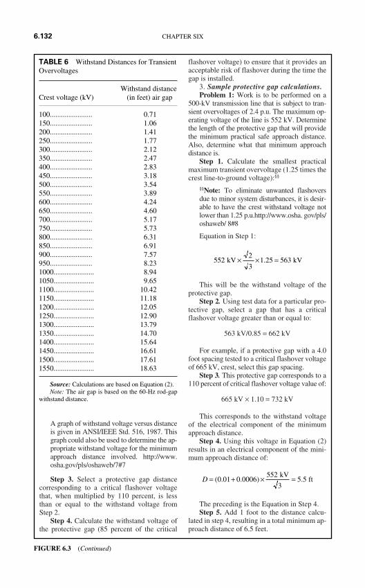
A graph of withstand voltage versus distanceis given in ANSI/IEEE Std. 516, 1987. Thisgraph could also be used to determine the ap-propriate withstand voltage for the minimumapproach distance involved. http://www.osha.gov/pls/oshaweb/7#7
Step 3. Select a protective gap distancecorresponding to a critical flashover voltagethat, when multiplied by 110 percent, is lessthan or equal to the withstand voltage fromStep 2.
Step 4. Calculate the withstand voltage ofthe protective gap (85 percent of the critical
flashover voltage) to ensure that it provides anacceptable risk of flashover during the time thegap is installed.
3. Sample protective gap calculations.Problem 1: Work is to be performed on a
500-kV transmission line that is subject to tran-sient overvoltages of 2.4 p.u. The maximum op-erating voltage of the line is 552 kV. Determinethe length of the protective gap that will providethe minimum practical safe approach distance.Also, determine what that minimum approachdistance is.
Step 1. Calculate the smallest practicalmaximum transient overvoltage (1.25 times thecrest line-to-ground voltage):§§
§§Note: To eliminate unwanted flashoversdue to minor system disturbances, it is desir-able to have the crest withstand voltage notlower than 1.25 p.u.http://www.osha. gov/pls/oshaweb/ 8#8
Equation in Step 1:
This will be the withstand voltage of theprotective gap.
Step 2. Using test data for a particular pro-tective gap, select a gap that has a criticalflashover voltage greater than or equal to:
563 kV/0.85 = 662 kV
For example, if a protective gap with a 4.0foot spacing tested to a critical flashover voltageof 665 kV, crest, select this gap spacing.
Step 3. This protective gap corresponds to a110 percent of critical flashover voltage value of:
665 kV × 1.10 = 732 kV
This corresponds to the withstand voltageof the electrical component of the minimumapproach distance.
Step 4. Using this voltage in Equation (2)results in an electrical component of the mini-mum approach distance of:
The preceding is the Equation in Step 4.Step 5. Add 1 foot to the distance calcu-
lated in step 4, resulting in a total minimum ap-proach distance of 6.5 feet.
D = + × =( . . ) .0 01 0 0006552
5 5 kV
3 ft
5522
31 25 563 kV kV× × =.
6.132 CHAPTER SIX
TABLE 6 Withstand Distances for TransientOvervoltages
Withstand distanceCrest voltage (kV) (in feet) air gap
100....................... 0.71150....................... 1.06200....................... 1.41250....................... 1.77300....................... 2.12350....................... 2.47400....................... 2.83450....................... 3.18500....................... 3.54550....................... 3.89600....................... 4.24650....................... 4.60700....................... 5.17750....................... 5.73800....................... 6.31850....................... 6.91900....................... 7.57950....................... 8.231000...................... 8.941050...................... 9.651100...................... 10.421150...................... 11.181200...................... 12.051250...................... 12.901300...................... 13.791350...................... 14.701400...................... 15.641450...................... 16.611500...................... 17.611550...................... 18.63
Source: Calculations are based on Equation (2).Note: The air gap is based on the 60-Hz rod-gap
withstand distance.
FIGURE 6.3 (Continued)
Problem 2: For a line operating at a maxi-mum voltage of 552 kV subject to a maximumtransient overvoltage of 2.4 p.u., find a protectivegap distance that will permit the use of a 9.0 footminimum approach distance. (A minimum ap-proach distance of 11 feet, 3 inches is normallyrequired.)
Step 1. The electrical component of the min-imum approach distance is 8.0 feet (9.0-1.0).
Step 2. From Table 6, select the withstandvoltage corresponding to a distance of 8.0 feet.By interpolation:
Step 3. The voltage calculated in Step 2 cor-responds to 110 percent of the critical flashovervoltage of the gap that should be employed.Using test data for a particular protective gap,select a gap that has a critical flashover voltageless than or equal to:
For example, if a protective gap with a 5.8 footspacing tested to a critical flashover voltage of 820kV, crest, select this gap spacing.
Step 4. The withstand voltage of this protec-tive gap would be:
820 kV × 0.85 = 697 kV.
The maximum operating crest voltage wouldbe:
The crest withstand voltage of the protectivegap in per unit is thus:
697 kV + 449 kV = 1.55 p.u
If this is acceptable, the protective gapcould be installed with a 5.8 foot spacing, andthe minimum approach distance could then bereduced to 9.0 feet.
4. Comments and variations. The 1 foot er-gonomic component of the minimum approachdistance must be added to the electrical compo-nent of the minimum approach distance calcu-lated under paragraph IV.D of this appendix.
The calculations may be varied by starting withthe protective gap distance or by starting withthe minimum approach distance.
E. Location of Protective Gaps 1. Installation of the protective gap on a
structure adjacent to the work site is an ac-ceptable practice, as this does not signifi-cantly reduce the protection afforded bythe gap.
2. Gaps installed at terminal stations of linesor circuits provide a given level of protec-tion. The level may not, however, extendthroughout the length of the line to theworksite. The use of gaps at terminal sta-tions must be studied in depth. The use ofsubstation terminal gaps raises the possi-bility that separate surges could enter theline at opposite ends, each with lowenough magnitude to pass the terminalgaps without flashover. When voltagesurges are initiated simultaneously at eachend of a line and travel toward each other,the total voltage on the line at the pointwhere they meet is the arithmetic sum ofthe two surges. A gap that is installedwithin 0.5 mile of the work site will protectagainst such intersecting waves. Engineer-ing studies of a particular line or systemmay indicate that adequate protection canbe provided by even more distant gaps.
3. If protective gaps are used at the work site,the work site impulse insulation strength isestablished by the gap setting. Lightningstrikes as much as 6 miles away from theworksite may cause a voltage surge greaterthan the insulation withstand voltage, and agap flashover may occur. The flashoverwill not occur between the employeeand the line, but across the protective gapinstead.
4. There are two reasons to disable the auto-matic-reclosing feature of circuit-inter-rupting devices while employees areperforming live-line maintenance:
To prevent the reenergizing of a circuitfaulted by actions of a worker, whichcould possibly create a hazard or com-pound injuries or damage produced bythe original fault;
To prevent any transient overvoltagecaused by the switching surge that wouldoccur if the circuit were reenergized.
However, due to system stability consider-ations, it may not always be feasible to disablethe automatic-reclosing feature.
5522
3449 kV kV× =
D = + ×( . . )0 01 0 0006
2732 kV
900 508 00 7 578 23 7 57
933( . . )( . . )
kV kV+ × −−
=
REGULATORY AND LEGAL SAFETY REQUIREMENTS AND STANDARDS 6.133
FIGURE 6.3 (Continued)
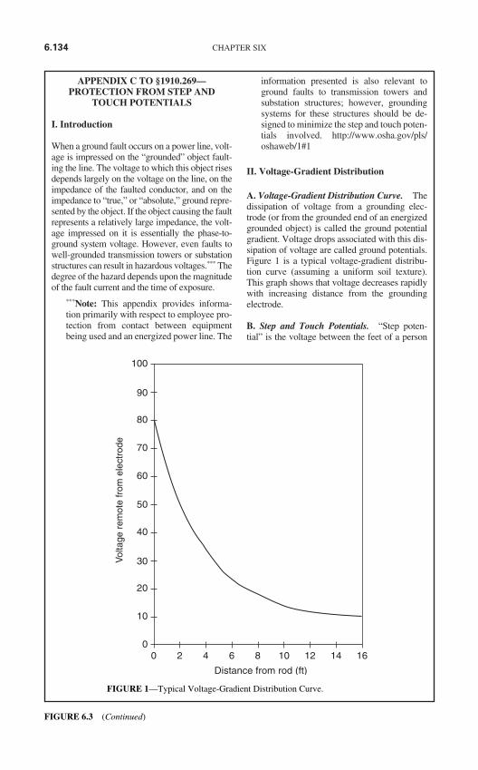
APPENDIX C TO §1910.269—PROTECTION FROM STEP AND
TOUCH POTENTIALS
I. Introduction
When a ground fault occurs on a power line, volt-age is impressed on the “grounded” object fault-ing the line. The voltage to which this object risesdepends largely on the voltage on the line, on theimpedance of the faulted conductor, and on theimpedance to “true,” or “absolute,” ground repre-sented by the object. If the object causing the faultrepresents a relatively large impedance, the volt-age impressed on it is essentially the phase-to-ground system voltage. However, even faults towell-grounded transmission towers or substationstructures can result in hazardous voltages.*** Thedegree of the hazard depends upon the magnitudeof the fault current and the time of exposure.
***Note: This appendix provides informa-tion primarily with respect to employee pro-tection from contact between equipmentbeing used and an energized power line. The
information presented is also relevant toground faults to transmission towers andsubstation structures; however, groundingsystems for these structures should be de-signed to minimize the step and touch poten-tials involved. http://www.osha.gov/pls/oshaweb/1#1
II. Voltage-Gradient Distribution
A. Voltage-Gradient Distribution Curve. Thedissipation of voltage from a grounding elec-trode (or from the grounded end of an energizedgrounded object) is called the ground potentialgradient. Voltage drops associated with this dis-sipation of voltage are called ground potentials.Figure 1 is a typical voltage-gradient distribu-tion curve (assuming a uniform soil texture).This graph shows that voltage decreases rapidlywith increasing distance from the groundingelectrode.
B. Step and Touch Potentials. “Step poten-tial” is the voltage between the feet of a person
6.134 CHAPTER SIX
00
10
20
30
40
50
60
70
80
90
100
2 4 6 8 10 12 14 16
Distance from rod (ft)
Volta
ge r
emot
e fr
om e
lect
rode
FIGURE 1—Typical Voltage-Gradient Distribution Curve.
FIGURE 6.3 (Continued)
standing near an energized grounded object. It isequal to the difference in voltage, given by thevoltage distribution curve, between two points atdifferent distances from the “electrode.” A per-son could be at risk of injury during a fault sim-ply by standing near the grounding point.
“Touch potential” is the voltage between theenergized object and the feet of a person in con-tact with the object. It is equal to the difference involtage between the object (which is at a distanceof 0 feet) and a point some distance away. Itshould be noted that the touch potential could benearly the full voltage across the grounded objectif that object is grounded at a point remote fromthe place where the person is in contact with it.For example, a crane that was grounded to thesystem neutral and that contacted an energizedline would expose any person in contact with thecrane or its uninsulated load line to a touch po-tential nearly equal to the full fault voltage.
Step and touch potentials are illustrated inFig. 2.
C. Protection From the Hazards of Ground-Potential Gradients. An engineering analy-sis of the power system under fault conditionscan be used to determine whether or not haz-ardous step and touch voltages will develop.The result of this analysis can ascertain theneed for protective measures and can guide theselection of appropriate precautions.
Several methods may be used to protectemployees from hazardous ground-potentialgradients, including equipotential zones, insu-lating equipment, and restricted work areas.
1. The creation of an equipotential zone willprotect a worker standing within it from haz-ardous step and touch potentials (See Fig. 3).Such a zone can be produced through the use ofa metal mat connected to the grounded object. Insome cases, a grounding grid can be used toequalize the voltage within the grid. Equipoten-tial zones will not, however, protect employeeswho are either wholly or partially outside theprotected area. Bonding conductive objects inthe immediate work area can also be used tominimize the potential between the objects andbetween each object and ground. (Bonding anobject outside the work area can increase thetouch potential to that object in some cases,however.)
2. The use of insulating equipment, such asrubber gloves, can protect employees handlinggrounded equipment and conductors from haz-ardous touch potentials. The insulating equip-ment must be rated for the highest voltage thatcan be impressed on the grounded objectsunder fault conditions (rather than for the fullsystem voltage).
3. Restricting employees from areas wherehazardous step or touch potentials could arisecan protect employees not directly involved in
REGULATORY AND LEGAL SAFETY REQUIREMENTS AND STANDARDS 6.135
Energizedgrounded object
Touchpotential
Voltagedistribution curve
Stoppotential
FIGURE 2—Step and Touch Potentials.
FIGURE 6.3 (Continued)
the operation being performed. Employees onthe ground in the vicinity of transmission struc-tures should be kept at a distance where stepvoltages would be insufficient to cause injury.Employees should not handle grounded conduc-tors or equipment likely to become energized tohazardous voltages unless the employees arewithin an equipotential zone or are protectedby insulating equipment.
APPENDIX D TO §1910.269—METHODSOF INSPECTING AND
TESTING WOOD POLES
I. “Introduction”
When work is to be performed on a wood pole,it is important to determine the condition of thepole before it is climbed. The weight of the em-ployee, the weight of equipment being in-stalled, and other working stresses (such as theremoval or retensioning of conductors) canlead to the failure of a defective pole or one thatis not designed to handle the additional
stresses.††† For these reasons, it is essential thatan inspection and test of the condition of awood pole be performed before it is climbed.
†††Note: A properly guyed pole in goodcondition should, at a minimum, be able tohandle the weight of an employee climbingit. If the pole is found to be unsafe to climbor to work from, it must be secured so thatit does not fall while an employee is on it.The pole can be secured by a line truckboom, by ropes or guys, or by lashing anew pole alongside it. If a new one islashed alongside the defective pole, workshould be performed from the new one.
II. “Inspection of Wood Poles”
Wood poles should be inspected by a qualifiedemployee for the following conditions:‡‡‡
‡‡‡Note: The presence of any of these con-ditions is an indication that the pole maynot be safe to climb or to work from. Theemployee performing the inspection must
6.136 CHAPTER SIX
Voltagedistribution
curve
Energizedgrounded object
Equipotential zone(see text.)
Step and touchpotential zone
FIGURE 3—Protection from Ground-Potential Gradients.
FIGURE 6.3 (Continued)
be qualified to make a determination as towhether or not it is safe to perform the workwithout taking additional precautions.
A. General Condition. The pole should beinspected for buckling at the ground line andfor an unusual angle with respect to the ground.Buckling and odd angles may indicate that thepole has rotted or is broken.
B. Cracks. The pole should be inspected forcracks. Horizontal cracks perpendicular to thegrain of the wood may weaken the pole. Verti-cal ones, although not considered to be a signof a defective pole, can pose a hazard to theclimber, and the employee should keep his orher gaffs away from them while climbing.
C. Holes. Hollow spots and woodpecker holescan reduce the strength of a wood pole.
D. Shell Rot and Decay. Rotting and decayare cutout hazards and are possible indicationsof the age and internal condition of the pole.
E. Knots. One large knot or several smallerones at the same height on the pole may be ev-idence of a weak point on the pole.
F. Depth of Setting. Evidence of the exis-tence of a former ground line substantiallyabove the existing ground level may be an indi-cation that the pole is no longer buried to a suf-ficient extent.
G. Soil Conditions. Soft, wet, or loose soilmay not support any changes of stress on thepole.
H. Burn Marks. Burning from transformerfailures or conductor faults could damage thepole so that it cannot withstand mechanicalstress changes.
III. “Testing of Wood Poles”
The following tests, which have been takenfrom 1910.268(n)(3), are recognized as accept-able methods of testing wood poles:
A. Hammer Test. Rap the pole sharply with ahammer weighing about 3 pounds, startingnear the ground line and continuing upwardscircumferentially around the pole to a height ofapproximately 6 feet. The hammer will pro-duce a clear sound and rebound sharply when
striking sound wood. Decay pockets will be in-dicated by a dull sound or a less pronouncedhammer rebound. Also, prod the pole as nearthe ground line as possible using a pole prod ora screwdriver with a blade at least 5 incheslong. If substantial decay is encountered, thepole is considered unsafe.
B. Rocking Test. Apply a horizontal force tothe pole and attempt to rock it back and forth ina direction perpendicular to the line. Cautionmust be exercised to avoid causing power linesto swing together. The force may be applied ei-ther by pushing with a pike pole or pulling witha rope. If the pole cracks during the test, it shallbe considered unsafe.
APPENDIX E TO §1910.269—REFERENCE DOCUMENTS
The references contained in this appendix pro-vide information that can be helpful in under-standing and complying with the requirementscontained in 1910.269. The national consensusstandards referenced in this appendix containdetailed specifications that employers may fol-low in complying with the more performance-oriented requirements of OSHA’s final rule.Except as specifically noted in 1910.269, how-ever, compliance with the national consensusstandards is not a substitute for compliancewith the provisions of the OSHA standard.
ANSI/SIA A92.2-1990, American Na-tional Standard for Vehicle-Mounted Elevatingand Rotating Aerial Devices.
ANSI C2-1993, National Electrical SafetyCode.
ANSI Z133.1-1988, American NationalStandard Safety Requirements for Pruning,Trimming, Repairing, Maintaining, and Remov-ing Trees, and for Cutting Brush.
ANSI/ASME B20.1-1990, Safety Standardfor Conveyors and Related Equipment.
ANSI/IEEE Std. 4-1978 (Fifth Printing),IEEE Standard Techniques for High-VoltageTesting.
ANSI/IEEE Std. 100-1988, IEEE StandardDictionary of Electrical and Electronic Terms.
ANSI/IEEE Std. 516-1987, IEEE Guide forMaintenance Methods on Energized Power-Lines.
ANSI/IEEE Std. 935-1989, IEEE Guide onTerminology for Tools and Equipment to BeUsed in Live Line Working.
REGULATORY AND LEGAL SAFETY REQUIREMENTS AND STANDARDS 6.137
FIGURE 6.3 (Continued)
ANSI/IEEE Std. 957-1987, IEEE Guide forCleaning Insulators.
ANSI/IEEE Std. 978-1984 (R1991), IEEEGuide for In-Service Maintenance and Electri-cal Testing of Live-Line Tools.
ASTM D 120-87, Specification for RubberInsulating Gloves.
ASTM D 149-92, Test Method for Dielec-tric Breakdown Voltage and DielectricStrength of Solid Electrical Insulating Materi-als at Commercial Power Frequencies.
ASTM D 178-93, Specification for RubberInsulating Matting.
ASTM D 1048-93, Specification for Rub-ber Insulating Blankets.
ASTM D 1049-93, Specification for Rub-ber Insulating Covers.
ASTM D 1050-90, Specification for Rub-ber Insulating Line Hose.
ASTM D 1051-87, Specification for Rub-ber Insulating Sleeves.
ASTM F 478-92, Specification for In-Ser-vice Care of Insulating Line Hose and Covers.
ASTM F 479-93, Specification for In-Ser-vice Care of Insulating Blankets.
ASTM F 496-93B, Specification for In-Service Care of Insulating Gloves and Sleeves.
ASTM F 711-89, Specification for Fiber-glass-Reinforced Plastic (FRP) Rod and TubeUsed in Live Line Tools.
ASTM F 712-88, Test Methods for Electri-cally Insulating Plastic Guard Equipment forProtection of Workers.
ASTM F 819-83a (1988), Definitions ofTerms Relating to Electrical Protective Equip-ment for Workers.
ASTM F 855-90, Specifications for Tem-porary Grounding Systems to Be Used on De-Energized Electric Power Lines and Equipment.
ASTM F 887-91a, Specifications for Per-sonal Climbing Equipment.
ASTM F 914-91, Test Method for AcousticEmission for Insulated Aerial PersonnelDevices.
ASTM F 968-93, Specification for Electri-cally Insulating Plastic Guard Equipment forProtection of Workers.
ASTM F 1116-88, Test Method for Deter-mining Dielectric Strength of OvershoeFootwear.
ASTM F 1117-87, Specification for Di-electric Overshoe Footwear.
ASTM F 1236-89, Guide for Visual Inspec-tion of Electrical Protective Rubber Products.
ASTM F 1505-94, Standard Specificationfor Insulated and Insulating Hand Tools.
ASTM F 1506-94, Standard PerformanceSpecification for Textile Materials for WearingApparel for Use by Electrical Workers Ex-posed to Momentary Electric Arc and RelatedThermal Hazards.
IEEE Std. 62-1978, IEEE Guide for FieldTesting Power Apparatus Insulation.
IEEE Std. 524-1992, IEEE Guide to the In-stallation of Overhead Transmission Line Con-ductors.
IEEE Std. 1048-1990, IEEE Guide for Pro-tective Grounding of Power Lines.
IEEE Std. 1067-1990, IEEE Guide for theIn-Service Use, Care, Maintenance, and Test-ing of Conductive Clothing for Use on Volt-ages up to 765 kV AC.
6.138 CHAPTER SIX
FIGURE 6.3 (Continued)
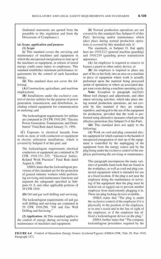
(Indented statements are quoted from thepreamble to this regulation and from theDirectorate of Compliance.)
(a) Scope, application and purpose(1) Scope(i) This standard covers the servicing and
maintenance of machines and equipment inwhich the unexpected energization or start up ofthe machines or equipment, or release of storedenergy could cause injury to employees. Thisstandard establishes minimum performance re-quirements for the control of such hazardousenergy.
(ii) This standard does not cover the fol-lowing:
(A) Construction, agriculture, and maritimeemployment;
(B) Installations under the exclusive con-trol of electric utilities for the purpose of powergeneration, transmission, and distribution, in-cluding related equipment for communicationor metering; and
The lockout/tagout requirements for utilitiesare contained in 29 CFR 1910.269, “ElectricPower Generation, Transmission, and Distri-bution” Final Rule dated January 31, 1994.
(C) Exposure to electrical hazards fromwork on, near, or with conductors or equipmentin electric utilization installations, which iscovered by Subpart S of this part; and
The lockout/tagout requirements electricalconductors or equipment are contained in 29CFR 1910.331-.335, “Electrical Safety-Related Work Practices” Final Rule datedAugust 6, 1990.
OSHA states that the lockout/tagout pro-visions of this standard are for the protectionof general industry workers while perform-ing servicing and maintenance functions andaugment the safeguards specified in Sub-parts O, S, and other applicable portions of29 CFR 1910.
(D) Oil and gas well drilling and servicing.
The lockout/tagout requirements oil and gaswell drilling and servicing are contained in29 CFR 1910.290, “Oil and Gas WellDrilling and Servicing.”
(2) Application. (i) This standard applies tothe control of energy during servicing and/ormaintenance of machines and equipment.
(ii) Normal production operations are notcovered by this standard (See Subpart O of thisPart). Servicing and/or maintenance whichtakes place during normal production opera-tions is covered by this standard only if:
The standards, in Subpart O, that applyhere are 1910.212 (general machine guarding)and 1910.219 (guarding power transmissionapparatus).
(A) An employee is required to remove orbypass a guard or other safety device; or
(B) An employee is required to place anypart of his or her body into an area on a machineor piece of equipment where work is actuallyperformed upon the material being processed(point of operation) or where an associated dan-ger zone exists during a machine operating cycle.
Note: Exception to paragraph (a)(2)(ii):Minor tool changes and adjustments, and otherminor servicing activities, which take place dur-ing normal production operations, are not cov-ered by this standard if they are routine,repetitive, and integral to the use of the equipmentfor production, provided that the work is per-formed using alternative measures which provideeffective protection (See Subpart O of this Part).
(iii) This standard does not apply to thefollowing:
(A) Work on cord and plug connected elec-tric equipment for which exposure to the hazards ofunexpected energization or start up of the equip-ment is controlled by the unplugging of theequipment from the energy source and by theplug being under the exclusive control of the em-ployee performing the servicing or maintenance.
This paragraph encompasses the many vari-eties of portable hand tools that are found inthe workplace, as well as cord and plug con-nected equipment which is intended for useat a fixed location. If the plug is not near theemployee doing the maintenance or servic-ing of the equipment then the plug must belocked out or tagged out to prevent anotheremployee from inadvertently plugging it in.There are plug locking devices available.
OSHA states that “The plug is underthe exclusive control of the employee if it isphysically in the position of the employee,or in arm’s reach and in the line of sight ofthe employee, or if the employee has af-fixed a lockout/tagout device on the plug.”
OSHA further states that “The companylockout/tagout procedures required by the
REGULATORY AND LEGAL SAFETY REQUIREMENTS AND STANDARDS 6.139
FIGURE 6.4 Control of Hazardous Energy Source (Lockout/Tagout) (OSHA-CFR, Title 29, Part 1910,Paragraph 147).
standard at 29 CFR 1910 .147(c)(4)(i) shallspecify the acceptable procedure for han-dling cord and plug connected equipment.”
(B) Hot tap operations involving transmis-sion and distribution systems for substancessuch as gas, steam, water, or petroleum productswhen they are performed on pressurized pipelines,provided that the employer demonstrates that1 continuity of service is essential; 2 shut-down of the system is impractical; and 3 docu-mented procedures are followed, and specialequipment is used which will provide proven ef-fective protection for employees.
(3) Purpose. (i) This section requires em-ployers to establish a program and utilize proce-dures for affixing appropriate lockout devices ortagout devices to energy isolating devices, andto otherwise disable machines or equipment toprevent unexpected energization, start up or re-lease of stored energy in order to prevent injuryto employees.
(ii) When other standards in this part requirethe use of lockout/tagout, they shall be used andsupplemented by the procedural and training re-quirements of this section.
“This part” means 1910. The requirementsof this standard also apply to 1910.331-.335 and 1910.269.
(b) Definitions applicable to this section.Affected employee. An employee whose
job requires him/her to operate or use a ma-chine or equipment on which servicing ormaintenance is being performed under lock-out/tagout, or whose job requires him/her towork in an area in which such servicing ormaintenance is being performed.
An affected employee is one who does not per-form the servicing or implement the energycontrol procedure, but whose responsibilitiesare performed in an area in which the energycontrol procedure is implemented and servic-ing operations are performed under that proce-dure. The affected employee does not need toknow how to perform lockout/tagout, nor doesthat employee need to be trained in the detailedimplementation of the energy control proce-dure. Rather, the affected employee need onlybe able to recognize when the energy controlprocedure is being implemented, to identifythe locks or tags being used, and to understandthe purpose of the procedures and the impor-tance of not attempting to start up or use theequipment which has been locked out ortagged out.
The definition of affected employeealso recognizes that an affected person andan authorized person may be one and thesame person when a machine operator oruser must also perform servicing or mainte-nance on the machine or equipment. In thiscase, the employee must have the requisiteknowledge of an authorized employee.
Authorized employee. A person who locksout or tags out machines or equipment in orderto perform servicing or maintenance on thatmachine or equipment. An affected employeebecomes an authorized employee when thatemployee’s duties include performing servic-ing or maintenance covered under this section.
OSHA agrees that as long as an employee isinvolved in performing an element of servic-ing and maintenance which is covered by theenergy control procedure, that employeeshould be considered and authorized em-ployee for the purpose of this standard. Thisis particularly important in the context of therequirement in paragraph (d)(3) “Machine orequipment isolation” as well as (f)(3)(ii)(D)of this standard, which requires the autho-rized person to affix a personal lockout ortagout device on the energy isolating deviceas part of the energy control procedure. Thisdefinition assures that when a servicing taskis performed by a team or group of employ-ees, each employee who is directly exposedto the hazards of the servicing operation willhave the responsibility to affix his/her per-sonal lockout/tagout device before beginningthe work and to remove it when he/she com-pletes the work.
Paragraph (c)(5)(ii)(D) of this standardprovides additional accountability by requir-ing such lockout and tagout devices to iden-tify the authorized person responsible forapplying them.
“Capable of being locked out.” An energyisolating device is capable of being locked outif it has a hasp or other means of attachment towhich, or through which, a lock can be affixed,or it has a locking mechanism built into it.Other energy isolating devices are capable ofbeing locked out, if lockout can be achievedwithout the need to dismantle, rebuild, or re-place the energy isolating device or perma-nently alter its energy control capability.
The capability for lockout does not necessar-ily mean that the equipment has an actualhasp or other physical attachment point for a
6.140 CHAPTER SIX
FIGURE 6.4 (Continued)
lock. For example, the use of chains can bean effective means of facilitating lockout ofmany types of valves, even if the valve doesnot have a specific locking point. Many ex-amples of equipment which was lockablewith minor modifications have been pro-vided to the record. For equipment of thistype, OSHA believes that the lockout capa-bility should be used in order to maximizethe protection afforded by this standard.
Energized. Connected to an energy sourceor containing residual or stored energy.
Energy isolating device. A mechanical de-vice that physically prevents the transmission orrelease of energy, including but not limited tothe following: A manually operated electricalcircuit breaker, a disconnect switch, a manuallyoperated switch by which the conductors of acircuit can be disconnected from all ungroundedsupply conductors and, in addition, no pole canbe operated independently; a line valve; a block;and any similar device used to block or isolateenergy. Push buttons, selector switches, andother control circuit type devices are not energyisolating devices.
Energy source. Any source of electrical,mechanical, hydraulic, pneumatic, chemical,thermal, or other energy.
The identification of energy sources, as de-fined here, is complicated by three very im-portant considerations: (1) Energy is alwayspresent in machinery, equipment, or processes;(2) energy is not necessarily dangerous; and(3) danger is only present when energy is re-leased in quantities or at rates that wouldharm an employee. Generally speaking, how-ever, potentially hazardous energy sourcesare defined as those that can cause injury toemployees working in, on, or around ma-chines or equipment.
Energy as used in this standard meansmechanical motion; potential energy due topressure, gravity, or springs; electrical en-ergy; or thermal energy resulting from highor low temperatures. Some energy sourcescan be turned on and off, some can be dis-sipated, some can be eliminated, and somecan only be controlled.
The following brief analysis of energysources may provide the reader with a bet-ter understanding of the provisions of thisstandard.
1. Mechanical motion can be linear transla-tion or rotation, or it can produce workwhich, in turn, produces changes in
temperature. This type of energy can beturned off or left on.
2. Potential energy can be due to pressure(above or below atmospheric) as in hy-draulic, pneumatic, or vacuum systems.Potential energy manifested as pressureor in springs can be dissipated or con-trolled; it cannot be turned off or on.
3. Electrical energy refers to generatedelectrical power or static electricity. Inthe case of generated electricity, theelectrical power can be turned on or off.Static electricity cannot be turned off; itcan only be dissipated or controlled.
4. Thermal energy is manifested by high orlow temperatures. This type of energy isthe result of mechanical work, radiation,chemical reaction, or electrical resis-tance. It cannot be turned off or elimi-nated; however, it can be dissipated orcontrolled.
Hot tap. A procedure used in the repair main-tenance and services activities which involveswelding on a piece of equipment (pipelines, ves-sels, or tanks) under pressure, in order to installconnections or appurtenances. It is commonlyused to replace or add sections of pipeline with-out the interruption of service for air, gas, water,steam, and petrochemical distribution systems.
Lockout. The placement of a lockout de-vice on an energy isolating device, in accor-dance with an established procedure, ensuringthat the energy isolating device and the equip-ment being controlled cannot be operated untilthe lockout device is removed.
Lockout device. A device that utilizes a pos-itive means such as a lock, either key or combi-nation type, to hold an energy isolating device inthe safe position and prevent the energizing of amachine or equipment.
Normal production operations. The uti-lization of a machine or equipment to performits intended production function.
Servicing and/or maintenance. Workplaceactivities such as constructing, installing, settingup, adjusting, inspecting, modifying, and main-taining and/or servicing machines or equipment.These activities include lubrication, cleaning, orunjamming of machines or equipment, and mak-ing adjustments or tool changes, where the em-ployee may be exposed to the unexpectedenergization or startup of the equipment or re-lease of hazardous energy.
Setting up. Any work performed to preparea machine or equipment to perform its normalproduction operation.
REGULATORY AND LEGAL SAFETY REQUIREMENTS AND STANDARDS 6.141
FIGURE 6.4 (Continued)
Tagout. The placement of a tagout deviceon an energy isolating device, in accordancewith an established procedure, to indicate thatthe energy isolating device and the equipmentbeing controlled may not be operated until thetagout device is removed.
Tagout device. A prominent warning de-vice, such as a tag and a means of attachment,which can be securely fastened to an energyisolating device in accordance with an estab-lished procedure, to indicate that the energyisolating device and the equipment being con-trolled may not be operated until the tagout de-vice is removed.
(c) General (1) Energy control program. Theemployer shall establish a program consistingof energy control procedures, employee train-ing, and to periodic inspections to ensure thatbefore any employee performs any servicing ormaintenance on a machine or equipment wherethe unexpected energizing, startup or release ofstored energy could occur and cause injury, themachine or equipment shall be isolated fromthe energy source and rendered inoperative.
The OSHA compliance officer is directed toask the employer for the documentation in-cluding:
1. procedures for the control of hazardousenergy including:a. shutdown,b. equipment isolation,c. lockout/tagout application,d. release of stored energy, ande. verification of isolation;
2. certification of periodic inspections; and3. certification of training.
The documented procedure must iden-tify the specific types of energy to be con-trolled and, in instances where a commonprocedure is to be used, the specific equip-ment covered by the common proceduremust be identified at least by type and loca-tion. The identification of the energy to becontrolled may be by magnitude and type ofenergy. See the exception to 147(c)(4)(i),“Note”. The employer need not documentthe required procedure for a particular ma-chine or equipment when all eight (8) ele-ments listed in the “Note” exist.
(2) Lockout/tagout. (i) If an energy isolat-ing device is not capable of being locked out,the employer’s energy control program underparagraph (c)(1) of this section shall utilize atagout system.
(ii) If an energy isolating device is capable ofbeing locked out, the employer’s energy controlprogram under paragraph (c)(1) of this sectionshall utilize lockout, unless the employer candemonstrate that the utilization of a tagout sys-tem will provide full employee protection as setforth in paragraph (c)(3) of this section.
(iii) After January 2, 1990, whenever re-placement or major repair, renovation or modifi-cation of a machine or equipment is performed,and whenever new machines or equipment areinstalled, energy isolating devices for such ma-chine or equipment shall be designed to accept alockout device.
(3) Full employee protection. (i) When atagout device is used on an energy isolating de-vice which is capable of being locked out, thetagout device shall be attached at the same lo-cation that the lockout device would have beenattached, and the employer shall demonstratethat the tagout program will provide a level ofsafety equivalent to that obtained by using alockout program.
(ii) In demonstrating that a level of safety isachieved in the tagout program which is equiva-lent to the level of safety obtained by using alockout program, the employer shall demon-strate full compliance with all tagout-relatedprovisions of this standard together with suchadditional elements as are necessary to providethe equivalent safety available from the use of alockout device.
Additional means to be considered as part ofthe demonstration of full employee protectionshall include the implementation of additionalsafety measures such as the removal of an isolat-ing circuit element, blocking of a controllingswitch, opening of an extra disconnecting de-vice, or the removal of a valve handle to reducethe likelihood of inadvertent energization.
(4) Energy control procedure. (i) Proce-dures shall be developed, documented, and uti-lized for the control of potentially hazardousenergy when employees are engaged in the ac-tivities covered by this section.
Note: Exception: The employer need notdocument the required procedure for a particularmachine or equipment, when all of the followingelements exist: (1) The machine or equipmenthas no potential for stored or residual energy orreaccumulation of stored energy after shut downwhich could endanger employees: (2) the ma-chine or equipment has a single energy sourcewhich can be readily identified and isolated:(3) the isolation and locking out of that energysource will completely de-energize and deactivate
6.142 CHAPTER SIX
FIGURE 6.4 (Continued)
the machine or equipment: (4) the machine orequipment is isolated from that energy sourceand locked out during servicing or maintenance:(5) a single lockout device will achieve a locked-out condition: (6) the lockout device is under theexclusive control of the authorized employeeperforming the servicing or maintenance: (7) theservicing or maintenance does not create hazardsfor other employees; and (8) the employer, in uti-lizing this exception, has had no accidents involv-ing the unexpected activation or reenergization ofthe machine or equipment during servicing ormaintenance.
The exception is intended to apply to situa-tions in which the procedure for deenergiza-tion, servicing, and reenergization can becarried out without detailed interactions ofenergy sources, machines, and employees.For example, a motor in a small machineshop is wired into a single electrical discon-nect, with no other source, and the motordoes not present the hazards of stored orresidual energy. When the motor needs re-pair, the authorized employee can isolate themotor from the single energy source andlock it out, using his/her personal lockoutdevice on the disconnect, in accordance withthe procedures set forth in the standard.
Under these conditions, and providedthat no other employees are exposed to haz-ards from the servicing operation, the ser-vicing may be performed without the needto document the energy control procedure.
(ii) The procedures shall clearly and specif-ically outline the scope, purpose, authorization,rules, and techniques to be utilized for the con-trol of hazardous energy, and the means to en-force compliance including, but not limited to,the following:
(A) A specific statement of the intendeduse of the procedure;
(B) Specific procedural steps for shuttingdown, isolating, blocking, and securing ma-chines or equipment to control hazardous en-ergy;
(C) Specific procedural steps for the place-ment, removal, and transfer of lockout/tagoutdevices and the responsibility for them; and
(D) Specific requirements for testing amachine or equipment to determine and verifythe effectiveness of lockout devices, tagoutdevices, and other energy control measures.
OSHA uses the word “specific” to empha-size the need to have a detailed procedure,one which clearly and specifically outlines
the steps to be followed. Overgeneralizationcan result in a document which has little orno meaning to the employee who must fol-low the procedure. However, whereas theprocedure is required to be written in detail,this does not mean that a separate proceduremust be written for each and every machineor piece of equipment. Similar machinesand/or equipment (those using the same typeand magnitude energy) which have the sameor similar types of controls can be coveredwith a single procedure.
The written energy control procedurerequired by this standard need not be overlycomplicated or detailed, depending on thecomplexity of the equipment and the con-trol measures to be utilized.
For example, if there is a single machinewith a single energy source that must be iso-lated, and the control means is simple, suchas opening an electrical disconnect and lock-ing out that energy source during servicing,the written procedure could be very simple.The steps set forth in the standard can be in-corporated into the procedure with very littledetail, reflecting the lack of complexity ofthe control measure. In addition, the em-ployer’s procedures may not need to beunique for a single machine or task, but canapply to a group of similar machines, typesof energy and tasks if a single procedure canaddress the hazards and the steps to be takensatisfactorily.
OSHA believes that because of the needto follow the steps in the energy control pro-cedure carefully and specifically, and thenumber of variables involved in controllinghazardous energy, a documented procedureis necessary for most energy control situa-tions. However, OSHA has determined thatin certain limited situations, documentationof the procedure will not add markedly to theprojections otherwise provided by the stan-dard.
These situations incorporate severalcommon elements:
1. There is a single source of hazardous en-ergy which can be easily identified andisolated, and there is no potential forstored or residual energy in the equip-ment. This greatly simplifies the proce-dure for controlling the energy, since thesingle energy source is all that needs tobe isolated.
2. The isolation and locking out of that sin-gle energy source will totally deenergize
REGULATORY AND LEGAL SAFETY REQUIREMENTS AND STANDARDS 6.143
FIGURE 6.4 (Continued)
and deactivate the machine or equip-ment. There are no collateral sources ofenergy which need to be addressed.
3. A full lockout of the energy source isachieved by a single lockout device whichis under the exclusive control of the autho-rized employee performing the servicingor maintenance. As used in this provision,exclusive control means that the autho-rized employee is the only person who canaffix or remove the device. The authorizedemployee follows all steps necessary fordeenergizing the equipment, verifying thedeenergization, performing the work, andreenergizing the equipment upon comple-tion of servicing. Because the energy con-trol elements are simple, with a singleenergy source being locked out and noother potential sources of unexpected acti-vation or energization, the authorized em-ployee can perform them without referringto a written document
4. While the equipment is locked out, theservicing or maintenance cannot exposeother employees to hazards. For exam-ple, shutdown and lockout of a conveyercannot cause jams or other hazards atother conveyers which feed into the con-veyer being serviced.
(5) Protective materials and hardware.(i) Locks, tags, chains, wedges, key blocks,adapter pins, self-locking fasteners, or otherhardware shall be provided by the employer forisolating, securing, or blocking of machines orequipment from energy sources.
To meet this requirement, the employer caneither issue devices to each employee re-sponsible for implementing energy controlmeasures, or can exercise the option ofsimply having a sufficient quantity of thedevices on hand at any given time and as-sign or distribute them to the employees asthe need arises. All authorized employeeswill need to have these devices available toattach to energy isolating devices wheneverthey perform servicing or maintenanceusing the energy control procedure.
(ii) Lockout/tagout devices shall be singu-larly identified; shall be the only device(s) usedfor controlling energy; shall not be used forother purposes; and shall meet the following re-quirements:
This restriction was imposed to ensure thatthe sight of a distinctive lock or tag will
provide a constant message of the use thatthe device is being put to and the restric-tions which this device is intended tocovey. If lockout or tagout devices are usedfor other purposes, they can lose their sig-nificance in the workplace.
For the energy control procedure to beeffective, these devices must have a singlemeaning to employees: “Do not energizethe equipment when such a device is af-fixed to it.”
(A) Durable. 1 Lockout and tagout devicesshall be capable of withstanding the environ-ment to which they are exposed for the maxi-mum period of time that exposure is expected.
2 Tagout devices shall be constructed andprinted so that exposure to weather conditionsor wet and damp locations will not cause thetag to deteriorate or the message on the tag tobecome illegible.
3 Tags shall not deteriorate when used incorrosive environments such as areas where acidand alkali chemicals are handled and stored.
OSHA requires that tagout devices must beconstructed and printed so that exposure toweather or other environmental conditionswhich exist in the workplace will not causethe tag to become unserviceable and/or themessage on the tag to become illegible. Forany sign, tag, or other message bearing item,the message must remain legible for the em-ployees to be able to ascertain the meaningand intent of the message. Devices which arenot exposed to harsh environments need notbe capable of withstanding such exposure.
(B) Standardized. Lockout and tagout de-vices shall be standardized within the facility inat least one of the following criteria: Color;shape; or size; and additionally, in the case oftagout devices, print and format shall be stan-dardized.
OSHA requires that lockout or tagout de-vices be standardized in order to be readilyidentifiable and distinguished from othersimilar devices found in the workplace. Inaddition, there is a requirement for the use ofa standardized print and format for tagoutdevices. This is done to ensure that thetagout devices, which rely exclusively onemployee recognition for their effective-ness, will be so unique as to minimize thechances of their being misidentified or theirmessage misinterpreted.
6.144 CHAPTER SIX
FIGURE 6.4 (Continued)
(C) Substantial. 1 Lockout devices.Lockout devices shall be substantial enough toprevent removal without the use of excessiveforce or unusual techniques, such as with theuse of bolt cutters or other metal cutting tools.
2 Tagout devices. Tagout devices, includ-ing their means of attachment, shall be substan-tial enough to prevent inadvertent or accidentalremoval. Tagout device attachment means shallbe of a non-reusable type, attachable by hand,self-locking, and non-releasable with a minimumunlocking strength of no less than 50 pounds andhaving the general design and basic characteris-tics of being at least equivalent to a one-piece allenvironment-tolerant nylon cable tie.
OSHA requires that “Tagout devices hav-ing reusable, non-locking, easily detach-able means of attachment (such as string,cord, or adhesive) are not permitted.”
The “tagout device” addressed here iswhen a tagout device is used instead of alockout device. If a tag is used in conjunc-tion with a lock then these restrictions donot apply.
OSHA requires that lockout and tagoutdevices be substantial enough to minimizethe possibility of premature removal.
The additional requirements for a tagoutdevice are being imposed to ensure that tagsdo not become disconnected or lost duringuse, thereby negating their effectiveness.
(D) Identifiable. Lockout and tagout de-vices shall indicate the identity of the employeeapplying the device(s).
Identification of the user provides an addi-tional degree of accountability to the overallprogram. It enables the employer to inspectthe application of the energy control proce-dure and determine which employees areproperly implementing its requirements. Iflocks or tags are not being properly attachedby an employee, Identification on the locksand tags will enable the employer to locatethat employee and correct the problempromptly, including additional training, asnecessary. For other employees, this require-ment will enable them to determine at aglance which authorized employees are per-forming a given servicing operation.
It puts them on notice that if questionsarise about the servicing or the energy con-trol procedure, the persons listed on the lock-out and tagout devices are the appropriatepersons to ask. The authorized employee hasthe additional assurance that other employees
know of his/her involvement in the servicing,and that only he/she is allowed to remove thedevice.
OSHA believes that knowing who ap-plied a lockout device to a machine orequipment can save time and lives. If anemployee, upon completing a job, forgets toremove a lockout device, the identity of theemployee can be immediately determinedand the employee made available to com-plete the procedure. If that employee cannotbe located, it is possible that he/she is stillworking on the equipment. It would then bepossible to check out the area and assurethat the employee and others are out of thedanger area before the device is removed.Marking a lockout or tagout device is a sim-ple way of identifying the person who ap-plies it, and can prevent the inadvertentreenergization or reactivation of equipmentbefore that employee has been located andhas moved clear of the equipment. Thus,marking the identity of the employee whouses a lockout or tagout device is an appro-priate safeguard.
Marking of the lockout or tagout devicescan also promote a sense of security in em-ployees, in that each device is the individualemployee’s device, used only for his or herprotection. This sense of identity also can beused to encourage willing utilization of theenergy control procedure. When an employeecan identify with a part of the program he/shecontrols for his/her own protection, that em-ployee will likely be an active participant inmaking the program work.
(iii) Tagout devices shall warn against haz-ardous conditions if the machine or equipmentis energized and shall include a legend such asthe following: Do Not Start. Do Not Open. DoNot Close. Do Not Energize. Do Not Operate.
OSHA states that the legend (major mes-sage) on the tagout devices must warnagainst hazardous conditions if the equip-ment is reenergized.
OSHA recognizes, however, that thesemessages may not be sufficient to cover allconditions involving hazardous energycontrol. For that reason, the above statedlegends are only examples of what must bestated. The use of graphics, pictographs, orother symbols to convey the messagewhich the tag represents serves the samepurpose as the written message and there-fore would be acceptable to OSHA.
REGULATORY AND LEGAL SAFETY REQUIREMENTS AND STANDARDS 6.145
FIGURE 6.4 (Continued)
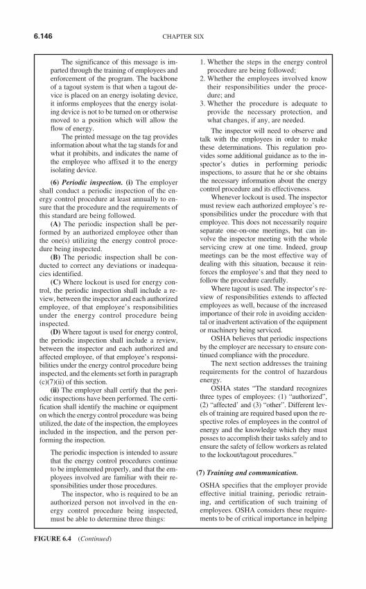
The significance of this message is im-parted through the training of employees andenforcement of the program. The backboneof a tagout system is that when a tagout de-vice is placed on an energy isolating device,it informs employees that the energy isolat-ing device is not to be turned on or otherwisemoved to a position which will allow theflow of energy.
The printed message on the tag providesinformation about what the tag stands for andwhat it prohibits, and indicates the name ofthe employee who affixed it to the energyisolating device.
(6) Periodic inspection. (i) The employershall conduct a periodic inspection of the en-ergy control procedure at least annually to en-sure that the procedure and the requirements ofthis standard are being followed.
(A) The periodic inspection shall be per-formed by an authorized employee other thanthe one(s) utilizing the energy control proce-dure being inspected.
(B) The periodic inspection shall be con-ducted to correct any deviations or inadequa-cies identified.
(C) Where lockout is used for energy con-trol, the periodic inspection shall include a re-view, between the inspector and each authorizedemployee, of that employee’s responsibilitiesunder the energy control procedure beinginspected.
(D) Where tagout is used for energy control,the periodic inspection shall include a review,between the inspector and each authorized andaffected employee, of that employee’s responsi-bilities under the energy control procedure beinginspected, and the elements set forth in paragraph(c)(7)(ii) of this section.
(ii) The employer shall certify that the peri-odic inspections have been performed. The certi-fication shall identify the machine or equipmenton which the energy control procedure was beingutilized, the date of the inspection, the employeesincluded in the inspection, and the person per-forming the inspection.
The periodic inspection is intended to assurethat the energy control procedures continueto be implemented properly, and that the em-ployees involved are familiar with their re-sponsibilities under those procedures.
The inspector, who is required to be anauthorized person not involved in the en-ergy control procedure being inspected,must be able to determine three things:
1. Whether the steps in the energy controlprocedure are being followed;
2. Whether the employees involved knowtheir responsibilities under the proce-dure; and
3. Whether the procedure is adequate toprovide the necessary protection, andwhat changes, if any, are needed.
The inspector will need to observe andtalk with the employees in order to makethese determinations. This regulation pro-vides some additional guidance as to the in-spector’s duties in performing periodicinspections, to assure that he or she obtainsthe necessary information about the energycontrol procedure and its effectiveness.
Whenever lockout is used. The inspectormust review each authorized employee’s re-sponsibilities under the procedure with thatemployee. This does not necessarily requireseparate one-on-one meetings, but can in-volve the inspector meeting with the wholeservicing crew at one time. Indeed, groupmeetings can be the most effective way ofdealing with this situation, because it rein-forces the employee’s and that they need tofollow the procedure carefully.
Where tagout is used. The inspector’s re-view of responsibilities extends to affectedemployees as well, because of the increasedimportance of their role in avoiding acciden-tal or inadvertent activation of the equipmentor machinery being serviced.
OSHA believes that periodic inspectionsby the employer are necessary to ensure con-tinued compliance with the procedure.
The next section addresses the trainingrequirements for the control of hazardousenergy.
OSHA states “The standard recognizesthree types of employees: (1) “authorized”,(2) “affected’ and (3) “other”. Different lev-els of training are required based upon the re-spective roles of employees in the control ofenergy and the knowledge which they mustposses to accomplish their tasks safely and toensure the safety of fellow workers as relatedto the lockout/tagout procedures.”
(7) Training and communication.
OSHA specifies that the employer provideeffective initial training, periodic retrain-ing, and certification of such training ofemployees. OSHA considers these require-ments to be of critical importance in helping
6.146 CHAPTER SIX
FIGURE 6.4 (Continued)
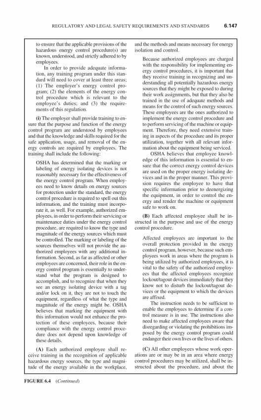
to ensure that the applicable provisions of thehazardous energy control procedure(s) areknown, understood, and strictly adhered to byemployees.
In order to provide adequate informa-tion, any training program under this stan-dard will need to cover at least three areas;(1) The employer’s energy control pro-gram; (2) the elements of the energy con-trol procedure which is relevant to theemployee’s duties; and (3) the require-ments of this regulation.
(i) The employer shall provide training to en-sure that the purpose and function of the energycontrol program are understood by employeesand that the knowledge and skills required for thesafe application, usage, and removal of the en-ergy controls are required by employees. Thetraining shall include the following:
OSHA has determined that the marking orlabeling of energy isolating devices is notreasonably necessary for the effectiveness ofthe energy control program. When employ-ees need to know details on energy sourcesfor protection under the standard, the energycontrol procedure is required to spell out thisinformation, and the training must incorpo-rate it, as well. For example, authorized em-ployees, in order to perform their servicing ormaintenance duties under the energy controlprocedure, are required to know the type andmagnitude of the energy sources which mustbe controlled. The marking or labeling of thesources themselves will not provide the au-thorized employees with any additional in-formation. Second, as far as affected or otheremployees are concerned, their role in the en-ergy control program is essentially to under-stand what the program is designed toaccomplish, and to recognize that when theysee an energy isolating device with a tagand/or lock on it, they are not to touch theequipment, regardless of what the type andmagnitude of the energy might be. OSHAbelieves that marking the equipment withthis information would not enhance the pro-tection of these employees, because theircompliance with the energy control proce-dure does not depend upon knowledge ofthese details.
(A) Each authorized employee shall re-ceive training in the recognition of applicablehazardous energy sources, the type and magni-tude of the energy available in the workplace,
and the methods and means necessary for energyisolation and control.
Because authorized employees are chargedwith the responsibility for implementing en-ergy control procedures, it is important thatthey receive training in recognizing and un-derstanding all potentially hazardous energysources that they might be exposed to duringtheir work assignments, but that they also betrained in the use of adequate methods andmeans for the control of such energy sources.These employees are the ones authorized toimplement the energy control procedure andto perform servicing of the machine or equip-ment. Therefore, they need extensive train-ing in aspects of the procedure and its properutilization, together with all relevant infor-mation about the equipment being serviced.
OSHA believes that employee knowl-edge of this information is essential to en-sure that the correct energy control devicesare used on the proper energy isolating de-vices and in the proper manner. This provi-sion requires the employee to have thatspecific information prior to deenergizingthe equipment, in order to control the en-ergy and render the machine or equipmentsafe to work on.
(B) Each affected employee shall be in-structed in the purpose and use of the energycontrol procedure.
Affected employees are important to theoverall protection provided in the energycontrol program, however, because such em-ployees work in areas where the program isbeing utilized by authorized employees, it isvital to the safety of the authorized employ-ees that the affected employees recognizelockout/tagout devices immediately that theyknow not to disturb the lockout/tagout de-vices or the equipment to which the devicesare affixed.
The instruction needs to be sufficient toenable the employees to determine if a con-trol measure is in use. The instructions alsoneed to make affected employees aware thatdisregarding or violating the prohibitions im-posed by the energy control program couldendanger their own lives or the lives of others.
(C) All other employees whose work oper-ations are or may be in an area where energycontrol procedures may be utilized, shall be in-structed about the procedure, and about the
REGULATORY AND LEGAL SAFETY REQUIREMENTS AND STANDARDS 6.147
FIGURE 6.4 (Continued)
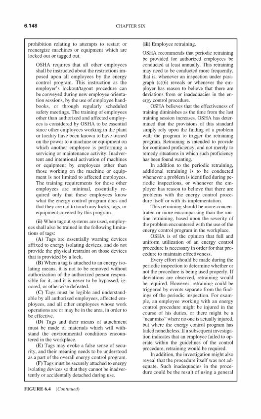
prohibition relating to attempts to restart orreenergize machines or equipment which arelocked out or tagged out.
OSHA requires that all other employeesshall be instructed about the restrictions im-posed upon all employees by the energycontrol program. This instruction as theemployer’s lockout/tagout procedure canbe conveyed during new employee orienta-tion sessions, by the use of employee hand-books, or through regularly scheduledsafety meetings. The training of employeesother than authorized and affected employ-ees is considered by OSHA to be essentialsince other employees working in the plantor facility have been known to have turnedon the power to a machine or equipment onwhich another employee is performing aservicing or maintenance activity. Inadver-tent and intentional activation of machinesor equipment by employees other thanthose working on the machine or equip-ment is not limited to affected employees.The training requirements for those otheremployees are minimal, essentially re-quired only that these employees knowwhat the energy control program does andthat they are not to touch any locks, tags, orequipment covered by this program.
(ii) When tagout systems are used, employ-ees shall also be trained in the following limita-tions of tags:
(A) Tags are essentially warning devicesaffixed to energy isolating devices, and do notprovide the physical restraint on those devicesthat is provided by a lock.
(B) When a tag is attached to an energy iso-lating means, it is not to be removed withoutauthorization of the authorized person respon-sible for it, and it is never to be bypassed, ig-nored, or otherwise defeated.
(C) Tags must be legible and understand-able by all authorized employees, affected em-ployees, and all other employees whose workoperations are or may be in the area, in order tobe effective.
(D) Tags and their means of attachmentmust be made of materials which will with-stand the environmental conditions encoun-tered in the workplace.
(E) Tags may evoke a false sense of secu-rity, and their meaning needs to be understoodas a part of the overall energy control program.
(F) Tags must be securely attached to energyisolating devices so that they cannot be inadver-tently or accidentally detached during use.
(iii) Employee retraining.
OSHA recommends that periodic retrainingbe provided for authorized employees beconducted at least annually. This retrainingmay need to be conducted more frequently,that is, whenever an inspection under para-graph (c)(6) reveals or whenever the em-ployer has reason to believe that there aredeviations from or inadequacies in the en-ergy control procedure.
OSHA believes that the effectiveness oftraining diminishes as the time from the lasttraining session increases. OSHA has deter-mined that the provisions of this standardsimply rely upon the finding of a problemwith the program to trigger the retrainingprogram. Retraining is intended to providefor continued proficiency, and not merely toremedy situations in which such proficiencyhas been found wanting.
In addition to the periodic retraining,additional retraining is to be conductedwhenever a problem is identified during pe-riodic inspections, or whenever the em-ployer has reason to believe that there areproblems with the energy control proce-dure itself or with its implementation.
This retraining should be more concen-trated or more encompassing than the rou-tine retraining, based upon the severity ofthe problem encountered with the use of theenergy control program in the workplace.
OSHA is of the opinion that full anduniform utilization of an energy controlprocedure is necessary in order for that pro-cedure to maintain effectiveness.
Every effort should be made during theperiodic inspection to determine whether ornot the procedure is being used properly. Ifdeviations are observed, retraining wouldbe required. However, retraining could betriggered by events separate from the find-ings of the periodic inspection. For exam-ple, an employee working with an energycontrol procedure might be injured in thecourse of his duties, or there might be a“near miss” where no one is actually injured,but where the energy control program hasfailed nonetheless. If a subsequent investiga-tion indicates that an employee failed to op-erate within the guidelines of the controlprocedure, retraining would be required.
In addition, the investigation might alsoreveal that the procedure itself was not ad-equate. Such inadequacies in the proce-dure could be the result of using a general
6.148 CHAPTER SIX
FIGURE 6.4 (Continued)
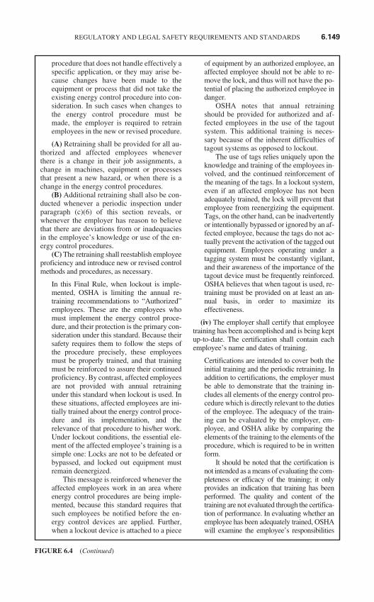
procedure that does not handle effectively aspecific application, or they may arise be-cause changes have been made to theequipment or process that did not take theexisting energy control procedure into con-sideration. In such cases when changes tothe energy control procedure must bemade, the employer is required to retrainemployees in the new or revised procedure.
(A) Retraining shall be provided for all au-thorized and affected employees wheneverthere is a change in their job assignments, achange in machines, equipment or processesthat present a new hazard, or when there is achange in the energy control procedures.
(B) Additional retraining shall also be con-ducted whenever a periodic inspection underparagraph (c)(6) of this section reveals, orwhenever the employer has reason to believethat there are deviations from or inadequaciesin the employee’s knowledge or use of the en-ergy control procedures.
(C) The retraining shall reestablish employeeproficiency and introduce new or revised controlmethods and procedures, as necessary.
In this Final Rule, when lockout is imple-mented, OSHA is limiting the annual re-training recommendations to “Authorized”employees. These are the employees whomust implement the energy control proce-dure, and their protection is the primary con-sideration under this standard. Because theirsafety requires them to follow the steps ofthe procedure precisely, these employeesmust be properly trained, and that trainingmust be reinforced to assure their continuedproficiency. By contrast, affected employeesare not provided with annual retrainingunder this standard when lockout is used. Inthese situations, affected employees are ini-tially trained about the energy control proce-dure and its implementation, and therelevance of that procedure to his/her work.Under lockout conditions, the essential ele-ment of the affected employee’s training is asimple one: Locks are not to be defeated orbypassed, and locked out equipment mustremain deenergized.
This message is reinforced whenever theaffected employees work in an area whereenergy control procedures are being imple-mented, because this standard requires thatsuch employees be notified before the en-ergy control devices are applied. Further,when a lockout device is attached to a piece
of equipment by an authorized employee, anaffected employee should not be able to re-move the lock, and thus will not have the po-tential of placing the authorized employee indanger.
OSHA notes that annual retrainingshould be provided for authorized and af-fected employees in the use of the tagoutsystem. This additional training is neces-sary because of the inherent difficulties oftagout systems as opposed to lockout.
The use of tags relies uniquely upon theknowledge and training of the employees in-volved, and the continued reinforcement ofthe meaning of the tags. In a lockout system,even if an affected employee has not beenadequately trained, the lock will prevent thatemployee from reenergizing the equipment.Tags, on the other hand, can be inadvertentlyor intentionally bypassed or ignored by an af-fected employee, because the tags do not ac-tually prevent the activation of the tagged outequipment. Employees operating under atagging system must be constantly vigilant,and their awareness of the importance of thetagout device must be frequently reinforced.OSHA believes that when tagout is used, re-training must be provided on at least an an-nual basis, in order to maximize itseffectiveness.
(iv) The employer shall certify that employeetraining has been accomplished and is being keptup-to-date. The certification shall contain eachemployee’s name and dates of training.
Certifications are intended to cover both theinitial training and the periodic retraining. Inaddition to certifications, the employer mustbe able to demonstrate that the training in-cludes all elements of the energy control pro-cedure which is directly relevant to the dutiesof the employee. The adequacy of the train-ing can be evaluated by the employer, em-ployee, and OSHA alike by comparing theelements of the training to the elements of theprocedure, which is required to be in writtenform.
It should be noted that the certification isnot intended as a means of evaluating the com-pleteness or efficacy of the training; it onlyprovides an indication that training has beenperformed. The quality and content of thetraining are not evaluated through the certifica-tion of performance. In evaluating whether anemployee has been adequately trained, OSHAwill examine the employee’s responsibilities
REGULATORY AND LEGAL SAFETY REQUIREMENTS AND STANDARDS 6.149
FIGURE 6.4 (Continued)
under the energy control program in relation tothe elements of the standard.
(8) Energy isolation. Lockout/tagout shallbe performed only by the authorized employ-ees who are performing the servicing ormaintenance.
These are the only employees who are re-quired to be trained to know in detail aboutthe types of energy available in the work-place and how to control the hazards of thatenergy. Only properly trained and qualifiedemployees can be relied on to deenergize andto properly lockout/tagout machines orequipment which are being serviced or main-tained, in order to ensure that the work willbe accomplished safely.
(9) Notification of employees. Affectedemployees shall be notified by the employer orauthorized employee of the application and re-moval of lockout devices or tagout devices.Notification shall be given before the controlsare applied, and after they are removed fromthe machine or equipment.
OSHA requires that whenever lockout/tagout control might directly affect anotheremployee’s work activities, the employeror authorized employee must notify the af-fected employee before taking any action toapply or to remove lockout/tagout devices.
OSHA believes that this requirement isan essential component of the total energycontrol program. Notification of affected em-ployees when lockout/tagout is going to beapplied provides the perfect opportunity forthe employer or authorized employee whonotifies them of the impending interruptionof the normal production operation to remindthem and reinforce the importance of the re-strictions imposed upon them by the energycontrol program.
OSHA believes that these measures areimportant to ensure that employees who op-erate or use machines or equipment do notunknowingly attempt to reenergize thosemachines or equipment that have been takenout of service and deenergized for the perfor-mance of activities covered by this standard.The lack of information regarding the statusof the equipment could endanger both theservicing employees and the employees at-tempting to reenergize or operate the equip-ment. Such notification is also needed afterservicing is completed to assure that employ-ees know when the control measures have
been removed. Without such information,employees might mistakenly believe that asystem is still deenergized and that it is safeto continue working on or around it.
The main thrust of the standard is tomandate the development, documentationand implementation of control procedures,and this is to be accomplished as outlinedin paragraph (d) of this standard. The em-ployer is given considerable flexibility indeveloping a control program, and such aprogram will be evaluated by OSHA com-pliance officers to determine whether itmeets all the criteria in this standard.
(d) Application of control. The establishedprocedures for the application of energy con-trol (the lockout/tagout procedures) shall coverthe following elements and actions, and shallbe done in the following sequence:
This section provides that six separate anddistinct steps be followed in meeting theprocedural requirements of paragraph(c)(1) and the application of energy control(lockout or tagout) measures, and that theactions be taken in the sequence presented.
(1) Preparation for shutdown. Before anauthorized or affected employee turns off a ma-chine or equipment, the authorized employeeshall have knowledge of the type and magni-tude of the energy, the hazards of the energy tobe controlled, and the method or means to con-trol the energy.
This paragraph requires that in preparationfor shutdown of machinery or equipment,the authorized employee must know aboutthe type and magnitude of the energy, thehazards involved and the means of control-ling them.
(This would require the authorizedperson to be qualified on the equipment orsystem.)
(2) Machine or equipment shutdown. Themachine or equipment shall be turned off orshut down using the procedures established forthe machine or equipment. An orderly shut-down must be utilized to avoid any additionalor increased hazard(s) to employees as a resultof the equipment stoppage.
This paragraph requires that the machine beturned off or shut down by an authorizedemployee according to established proce-dures. This is the starting point for all subse-quent actions necessary to put the machine
6.150 CHAPTER SIX
FIGURE 6.4 (Continued)
or equipment in a state that will permit em-ployees to work on it safely.
In many operations, activation of an elec-trical push-button control or the movement ofa simple throw switch (electrical, hydraulic,or pneumatic) to the “stop” or “off” mode issufficient to meet this provision. In othercases, however, such as those found typicallyin a refining or chemical process, there arecontrol devices that do not necessarily ad-dress an “off-on” or “start-stop” condition(i.e., level controls, pressure controllers, etc.).In these instances, a series of predeterminedsteps may be necessary to achieve a shut-down of the machine or equipment.
OSHA is aware that although an autho-rized employee would usually have the nec-essary knowledge and capability to shutdown machines or equipment, a machine orequipment operator or user should also be ina position and know how to shut down themachine or equipment he or she is utilizing.
In many cases, allowing a machine orequipment operator or user to shut it downwhen something goes wrong may save timeand money, and may possibly avoid an acci-dent. In many cases, the affected employeemay be infinitely more familiar with the shut-down procedure for the machine or equip-ment, and would be able to accomplish theshutdown more rapidly and safely than an au-thorized person who does not work with thatparticular machine or equipment every day.
In the event that a machine or equipmentmalfunctions, the wise and prudent thing todo in most cases is to require the machine orequipment be immediately shut down. Shut-ting down a machine or equipment is analo-gous to stopping the production operation.OSHA believes that stopping the machine’sproduction function is the necessary and ap-propriate first step in the procedure. OSHAalso believes that the necessary first step is tointerrupt the production process to allownon-servicing (affected) personnel to moveclear of the machine or equipment. Once thisis done and employees are not exposed to ahazard, the machine or equipment can berestarted by the authorized employee underthe guidelines of paragraph (f)(1) when nec-essary to allow positioning of the machine orequipment, or components thereof.
(3) Machine or equipment isolation. Allenergy isolating devices that are needed to con-trol the energy to the machine or equipmentshall be physically located and operated in such
a manner as to isolate the machine or equip-ment from the energy source(s).
Following the shutdown of the machine orequipment, paragraph (d)(3), as the next stepin the procedure, provides that energy isola-tion devices be physically located and oper-ated in such a manner as to isolate themachine or equipment from the energysource(s). For example, once an electricalpush-button control has been utilized to stopthe movement of machine or equipment partsas the first step of the shutdown procedure,isolation can then be accomplished by assur-ing that the push-button circuitry cannot besupplied with additional electrical energy.For such equipment, the isolation require-ment can be accomplished by the employee’sactions in tracing the path from the controltoward the energy source until he/she locatesthe energy isolating device, and moving theenergy isolating device control lever to the“safe,” “off,” or “open” position. Performingthese actions will prevent the reintroductionof energy to the push-button circuitry andwill isolate the operating control and the ma-chine or equipment from the energy source.
(4) Lockout or tagout device application.(i) Lockout or tagout devices shall be affixedto each energy isolating device by authorizedemployees.
(ii) Lockout devices, where used, shall beaffixed in a manner that will hold the energyisolating devices in a “safe” or “off” position.
(iii) Tagout devices, where used, shall beaffixed in such a manner as will clearly indi-cate that the operation or movement of energyisolating devices from the “safe” or “off” posi-tion is prohibited.
(A) Where tagout devices are used with en-ergy isolating devices designed with the capa-bility of being locked, the tag attachment shallbe fastened at the same point at which the lockwould have been attached.
(B) Where a tag cannot be affixed directlyto the energy isolating device, the tag shall belocated as close as safely possible to the device,in a position that will be immediately obviousto anyone attempting to operate the device.
As the fourth step in the procedure, paragraph(d)(4) provides that action be taken to securethe energy isolating devices in the “safe” or“off” position. This paragraph requires thatappropriate and effective lockout/tagout de-vices be affixed to each energy isolating de-vice by an authorized employee, and that they
REGULATORY AND LEGAL SAFETY REQUIREMENTS AND STANDARDS 6.151
FIGURE 6.4 (Continued)
be attached so as to prevent reactivation of themachine or equipment.
OSHA is of the opinion that, as a gen-eral rule, when it is feasible, the physicalprotection offered by the use of a lock,when supported by the information pro-vided on a tag used in conjunction with thelock, provides the greatest assurance of em-ployee protection from the release of haz-ardous energy.
(5) Stored energy. (i) Following the appli-cation of lockout or tagout devices to energyisolating devices, all potentially hazardousstored or residual energy shall be relieved, dis-connected, restrained, and otherwise renderedsafe.
(ii) If there is a possibility of reaccumula-tion of stored energy to a hazardous level, ver-ification of isolation shall be continued untilthe servicing or maintenance is completed, oruntil the possibility of such accumulation nolonger exists.
Paragraph (d)(5) provides that the next steptaken in the energy control procedure is todetermine the presence of, and relieve, dis-connect and/or restrain all potentially haz-ardous, stored or residual energy in themachine or equipment. Up to this point, thepurpose of following all the steps of the pro-cedure has been to enable the employee toisolate and block the source of energy feed-ing the machine or equipment to be workedon, at a point beyond which it can not be by-passed. However, energy can very easily betrapped in a system down-stream from anenergy isolating device, or can be present inthe form of potential energy from gravity orfrom spring action.
Stored or residual energy of this sortcannot be turned on or off; it must be dissi-pated or controlled.
When energy may still be present in asystem that has been isolated from the en-ergy source, this paragraph requires thatenergy to be controlled before an employeeattempts to perform any work covered bythe scope of this standard. Compliance withthis provision might require, for example,the use of blocks or other physical re-straints to immobilize the machine, ma-chine components, or equipment wherenecessary for control of the hazard. In thecase of electrical circuits, grounding mightbe necessary to discharge hazardous en-ergy. Hydraulic or pneumatic systems
might necessitate the use of bleed valves torelieve the pressure.
OSHA believes that these requirementsmust be utilized since there is no manner toensure that some leakage or drainage of en-ergy or energy containing substances, suchas super cooled or cryogenic fluids, canoccur. In the case of one of those sub-stances being present in a piping, contain-ment, or transport system, a certain amountof leakage may occur without endangeringemployees. However, if servicing or main-tenance must be performed on such a sys-tem, the standard requires the employer tocontinue to verify the isolation of energysources which may be hazardous, in orderto assure that such leakage does not ap-proach a dangerous level. This may involvemeans, such as continuous monitoring forthe displacement of oxygen or the buildupof the concentration of the substance to-ward the lower explosive limit of the sub-stance, such as could occur with ahydrogen system.
(6) Verification of isolation. Prior to startingwork on machines or equipment that have beenlocked/tagged out, the authorized employee shallverify that isolation and deenergization of themachine or equipment have been accomplished.
In this paragraph, as the sixth step in the en-ergy control procedure, the authorized em-ployee must ensure that the previous stepsof the procedure have been taken to isolatethe machine or equipment effectively. Thismust be done prior to starting the servicingor maintenance work. The authorized em-ployee needs to verify that the machine orequipment has been turned off or shutdown properly; that all energy isolating de-vices were identified, located and operated;that the lockout or tagout devices have beenattached to energy isolating devices; andthat stored energy has been rendered safe.
(e) Release from lockout or tagout. Beforelockout or tagout devices are removed and en-ergy is restored to the machine or equipment,procedures shall be followed and actions takenby the authorized employee(s) to ensure thefollowing:
(1) The machine or equipment. The workarea shall be inspected to ensure that non-essential items have been removed and to en-sure that machine or equipment componentsare operationally intact.
6.152 CHAPTER SIX
FIGURE 6.4 (Continued)
(2) Employees. (i) The work area shall bechecked to ensure that all employees have beensafely positioned or removed.
(ii) Before lockout or tagout devices are re-moved and before machines or equipment are en-ergized, affected employees shall be notified thatthe lockout or tagout devices have been removed.
(iii) After lockout or tagout devices havebeen removed and before a machine or equip-ment is started, affected employees shall be no-tified that the lockout or tagout device(s) havebeen removed.
(3) Lockout or tagout devices removal. Eachlockout or tagout device shall be removed fromeach energy isolating device by the employeewho applied the device. Exception to paragraph(e)(3): When the authorized employee who ap-plied the lockout or tagout device is not availableto remove it, that device may be removed underthe direction of the employer, provided that spe-cific procedures and training for such removalhave been developed, documented and incorpo-rated into the employer’s energy control pro-gram. The employer shall demonstrate that thespecific procedure shall include at least the fol-lowing elements:
(i) Verification by the employer that the au-thorized employee who applied the device isnot at the facility:
(ii) Making all reasonable efforts to contactthe authorized employee to inform him/her thathis/her lockout or tagout device has been re-moved; and
(iii) Ensuring that the authorized employeehas this knowledge before he/she resumeswork at that facility.
(f) Additional requirements. (1) Testing orpositioning of machines, equipment or compo-nents thereof. In situations in which lockout ortagout devices must be temporarily removedfrom the energy isolating device and the machineor equipment energized to test or position themachine, equipment or component thereof, thefollowing sequence of actions shall be followed:
(i) Clear the machine or equipment of toolsand materials in accordance with paragraph(e)(1) of this section;
(ii) Remove employees from the machineor equipment area in accordance with para-graph (e)(2) of this section;
(iii) Remove the lockout or tagout devices asspecified in paragraph (e)(3) of this section;
(iv) Energize and proceed with testing orpositioning;
(v) De-energize all systems and reapply en-ergy control measures in accordance with
paragraph (d) of this section to continue theservicing and/or maintenance.
(2) Outside personnel (contractors, etc.).(i) Whenever outside servicing personnel are tobe engaged in activities covered by the scope andapplication of this standard, the on-site employerand the outside employer shall inform each otherof their respective lockout or tagout procedures.
(ii) The on-site employer shall ensure thathis/her employees understand and comply withthe restrictions and prohibitions of the outsideemployer’s energy control program.
(3) Group lockout or tagout. (i) When ser-vicing and/or maintenance is performed by acrew, craft, department, or other group, theyshall utilize a procedure which affords the em-ployees a level of protection equivalent to thatprovided by the implementation of a personallockout or tagout device.
(ii) Group lockout or tagout devices shallbe used in accordance with the procedures re-quired by paragraph (c)(4) of this section in-cluding, but not necessarily limited to, thefollowing specific requirements:
(A) Primary responsibility is vested in anauthorized employee for a set number of em-ployees working under the protection of agroup lockout or tagout device (such as an op-erations lock);
(B) Provision for the authorized employeeto ascertain the exposure status of individualgroup members with regard to the lockout ortagout of the machine or equipment and
(C) When more than one crew, craft,department, etc. is involved, assignment of over-all job-associated lockout or tagout control re-sponsibility to an authorized employee designatedto coordinate affected work forces and ensurecontinuity of protection; and
(D) Each authorized employee shall affix apersonal lockout or tagout device to the grouplockout device, group lockbox, or comparablemechanism when he or she begins work, andshall remove those devices when he or shestops working on the machine or equipmentbeing serviced or maintained.
(4) Shift or personnel changes. Specificprocedures shall be utilized during shift or per-sonnel changes to ensure the continuity of lock-out or tagout protection, including provision forthe orderly transfer of lockout or tagout deviceprotection between off-going and oncomingemployees, to minimize exposure to hazardsfrom the unexpected energization or start-up ofthe machine or equipment, or the release ofstored energy.
REGULATORY AND LEGAL SAFETY REQUIREMENTS AND STANDARDS 6.153
FIGURE 6.4 (Continued)
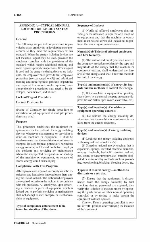
APPENDIX A—TYPICAL MINIMALLOCKOUT OR TAGOUT SYSTEM
PROCEDURES
General
The following simple lockout procedure is pro-vided to assist employers in developing their pro-cedures so they meet the requirements of thisstandard. When the energy isolating devices arenot lockable, tagout may be used, provided theemployer complies with the provisions of thestandard which require additional training andmore rigorous periodic inspections. When tagoutis used and the energy isolating devices are lock-able, the employer must provide full employeeprotection (see paragraph (c)(3)) and additionaltraining and more rigorous periodic inspectionsare required. For more complex systems, morecomprehensive procedures may need to be de-veloped, documented, and utilized.
Lockout/Tagout Procedure
Lockout Procedure for
(Name of Company for single procedure oridentification of equipment if multiple proce-dures are used).
Purpose
This procedure establishes the minimum re-quirements for the lockout of energy isolatingdevices whenever maintenance or servicing isdone on machines or equipment. It shall beused to ensure that the machine or equipment isstopped, isolated from all potentially hazardousenergy sources, and locked out before employ-ees perform any servicing or maintenancewhere the unexpected energization, or start-upof the machine or equipment, or release ofstored energy could cause injury.
Compliance With This Program
All employees are required to comply with the re-strictions and limitations imposed upon them dur-ing the use of lockout. The authorized employeesare required to perform the lockout in accordancewith this procedure. All employees, upon observ-ing a machine or piece of equipment which islocked out to perform servicing or maintenanceshall not attempt to start, energize, or use that ma-chine or equipment.
Type of compliance enforcement to betaken for violation of the above.
Sequence of Lockout
(1) Notify all affected employees that ser-vicing or maintenance is required on a machineor equipment and that the machine or equip-ment must be shut down and locked out to per-form the servicing or maintenance.
Name(s)/Job Title(s) of affected employeesand how to notify.
(2) The authorized employee shall refer tothe company procedure to identify the type andmagnitude of the energy that the machine orequipment utilizes, shall understand the haz-ards of the energy, and shall know the methodsto control the energy.
Type(s) and magnitude(s) of energy, its haz-ards and the methods to control the energy.
(3) If the machine or equipment is operating,shut it down by the normal stopping procedure (de-press the stop button, open switch, close valve, etc.).
Type(s) and location(s) of machine orequipment operating controls.
(4) De-activate the energy isolating de-vice(s) so that the machine or equipment is iso-lated from the energy source(s).
Type(s) and location(s) of energy isolatingdevices.
(5) Lock out the energy isolating device(s)with assigned individual lock(s).
(6) Stored or residual energy (such as that incapacitors, springs, elevated machine members,rotating flywheels, hydraulic systems, and air,gas, steam, or water pressure, etc.) must be dissi-pated or restrained by methods such as ground-ing, repositioning, blocking, bleeding down, etc.
Type(s) of stored energy—methods todissipate or restrain.
(7) Ensure that the equipment is discon-nected from the energy source(s) by firstchecking that no personnel are exposed, thenverify the isolation of the equipment by operat-ing the push button or other normal operatingcontrol(s) or by testing to make certain theequipment will not operate.
Caution: Return operating control(s) to neu-tral or “off” position after verifying the isolationof the equipment.
6.154 CHAPTER SIX
FIGURE 6.4 (Continued)
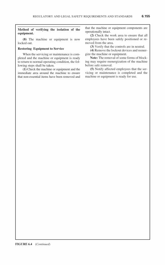
Method of verifying the isolation of theequipment.
(8) The machine or equipment is nowlocked out.
Restoring Equipment to Service
When the servicing or maintenance is com-pleted and the machine or equipment is readyto return to normal operating condition, the fol-lowing steps shall be taken.
(1) Check the machine or equipment and theimmediate area around the machine to ensurethat non-essential items have been removed and
that the machine or equipment components areoperationally intact.
(2) Check the work area to ensure that allemployees have been safely positioned or re-moved from the area.
(3) Verify that the controls are in neutral.(4) Remove the lockout devices and reener-
gize the machine or equipment.Note: The removal of some forms of block-
ing may require reenergization of the machinebefore safe removal.
(5) Notify affected employees that the ser-vicing or maintenance is completed and themachine or equipment is ready for use.
REGULATORY AND LEGAL SAFETY REQUIREMENTS AND STANDARDS 6.155
FIGURE 6.4 (Continued)
§ 1910.399 Definitions applicable to this subpart.
(a) Definitions applicable to 1910.302through 1910.330—
Acceptable. An installation or equipment isacceptable to the Assistant Secretary of Labor,and approved within the meaning of this Sub-part S:
(i) If it is accepted, or certified, or listed, orlabeled, or otherwise determined to be safe bya nationally recognized testing laboratory; or
(ii) With respect to an installation or equip-ment of a kind which no nationally recognizedtesting laboratory accepts, certifies, lists, labels,or determines to be safe, if it is inspected ortested by another Federal agency, or by a State,municipal, or other local authority responsiblefor enforcing occupational safety provisions ofthe National Electrical Code, and found in com-pliance with the provisions of the NationalElectrical Code as applied in this subpart; or
(iii) With respect to custom-made equip-ment or related installations which are de-signed, fabricated for, and intended for use by aparticular customer, if it is determined to besafe for its intended use by its manufacturer onthe basis of test data which the employer keepsand makes available for inspection to the As-sistant Secretary and his authorized representa-tives. Refer to 1910.7 for definition of nationallyrecognized testing laboratory.
Accepted. An installation is “accepted” if ithas been inspected and found by a nationallyrecognized testing laboratory to conform tospecified plans or to procedures of applicablecodes.
Accessible. (As applied to wiring methods.)Capable of being removed or exposed withoutdamaging the building structure or finish, ornot permanently closed in by the structure orfinish of the building. (See “concealed” and“exposed.”)
Accessible. (As applied to equipment.) Ad-mitting close approach; not guarded by lockeddoors, elevation, or other effective means. (See“Readily accessible.”)
Ampacity. Current-carrying capacity ofelectric conductors expressed in amperes.
Appliances. Utilization equipment, gener-ally other than industrial, normally built instandardized sizes or types, which is installedor connected as a unit to perform one or morefunctions such as clothes washing, air condi-tioning, food mixing, deep frying, etc.
Approved. Acceptable to the authority en-forcing this subpart. The authority enforcingthis subpart is the Assistant Secretary of Laborfor Occupational Safety and Health. The defin-ition of “acceptable” indicates what is accept-able to the Assistant Secretary of Labor, andtherefore approved within the meaning of thisSubpart.
Approved for the purpose. Approved for aspecific purpose, environment, or applicationdescribed in a particular standard requirement.
Suitability of equipment or materials for aspecific purpose, environment or applicationmay be determined by a nationally recognizedtesting laboratory, inspection agency or otherorganization concerned with product evalua-tion as part of its listing and labeling program.(See Labeled or Listed.)
Armored cable. Type AC armored cable is afabricated assembly of insulated conductors ina flexible metallic enclosure.
Askarel. A generic term for a group of non-flammable synthetic chlorinated hydrocarbonsused as electrical insulating media. Askarels ofvarious compositional types are used. Underarcing conditions the gases produced, whileconsisting predominantly of noncombustiblehydrogen chloride, can include varyingamounts of combustible gases depending uponthe askarel type.
Attachment plug (Plug cap)(Cap). A devicewhich, by insertion in a receptacle, estab-lishes connection between the conductors ofthe attached flexible cord and the conductorsconnected permanently to the receptacle.
Automatic. Self-acting, operating by its ownmechanism when actuated by some impersonalinfluence, as, for example, a change in currentstrength, pressure, temperature, or mechanicalconfiguration.
Bare conductor. See Conductor.Bonding. The permanent joining of metallic
parts to form an electrically conductive pathwhich will assure electrical continuity and thecapacity to conduct safely any current likely tobe imposed.
Bonding jumper. A reliable conductor to as-sure the required electrical conductivity be-tween metal parts required to be electricallyconnected.
Branch circuit. The circuit conductors be-tween the final overcurrent device protectingthe circuit and the outlet(s).
Building. A structure which stands alone orwhich is cut off from adjoining structures by
6.156 CHAPTER SIX
FIGURE 6.5 Definitions Applying to Part 1910, Subpart S (OSHA-CFR, Title 29, Part 1910, Paragraph399).
fire walls with all openings therein protectedby approved fire doors.
Cabinet. An enclosure designed either forsurface or flush mounting, and provided with aframe, mat, or trim in which a swinging door ordoors are or may be hung.
Cable tray system. A cable tray system is aunit or assembly of units or sections, and asso-ciated fittings, made of metal or other noncom-bustible materials forming a rigid structuralsystem used to support cables. Cable tray sys-tems include ladders, troughs, channels, solidbottom trays, and other similar structures.
Cablebus. Cablebus is an approved assem-bly of insulated conductors with fittings andconductor terminations in a completely en-closed, ventilated, protective metal housing.
Center pivot irrigation machine. A centerpivot irrigation machine is a multi-motored ir-rigation machine which revolves around a cen-tral pivot and employs alignment switches orsimilar devices to control individual motors.
Certified. Equipment is “certified” if it (a)has been tested and found by a nationally rec-ognized testing laboratory to meet nationallyrecognized standards or to be safe for use in aspecified manner, or (b) is of a kind whose pro-duction is periodically inspected by a nationallyrecognized testing laboratory, and (c) it bears alabel, tag, or other record of certification.
Circuit breaker. (i) (600 volts nominal, orless). A device designed to open and close acircuit by nonautomatic means and to open thecircuit automatically on a predetermined over-current without injury to itself when properlyapplied within its rating.
(ii) (Over 600 volts, nominal). A switchingdevice capable of making, carrying, and break-ing currents under normal circuit conditions,and also making, carrying for a specified time,and breaking currents under specified abnor-mal circuit conditions, such as those of shortcircuit.
Class I locations. Class I locations are thosein which flammable gases or vapors are or maybe present in the air in quantities sufficient toproduce explosive or ignitable mixtures. ClassI locations include the following:
(i) Class I, Division 1. A Class I, Division 1location is a location: (a) in which hazardousconcentrations of flammable gases or vaporsmay exist under normal operating conditions; or(b) in which hazardous concentrations of suchgases or vapors may exist frequently because ofrepair or maintenance operations or because of
leakage; or (c) in which breakdown or faultyoperation of equipment or processes might re-lease hazardous concentrations of flammablegases or vapors, and might also cause simulta-neous failure of electric equipment.
NOTE: This classification usually includes loca-tions where volatile flammable liquids or liquefiedflammable gases are transferred from one con-tainer to another; interiors of spray booths andareas in the vicinity of spraying and painting oper-ations where volatile flammable solvents are used;locations containing open tanks or vats of volatileflammable liquids; drying rooms or compartmentsfor the evaporation of flammable solvents; loca-tions containing fat and oil extraction equipmentusing volatile flammable solvents; portions ofcleaning and dyeing plants where flammable liq-uids are used; gas generator rooms and other por-tions of gas manufacturing plants whereflammable gas may escape; inadequately venti-lated pump rooms for flammable gas or forvolatile flammable liquids; the interiors of refrig-erators and freezers in which volatile flammablematerials are stored in open, lightly stoppered, oreasily ruptured containers; and all other locationswhere ignitable concentrations of flammablevapors or gases are likely to occur in the course ofnormal operations.
(ii) Class I, Division 2. A Class I, Division2 location is a location: (a) in which volatileflammable liquids or flammable gases are han-dled, processed, or used, but in which the haz-ardous liquids, vapors, or gases will normallybe confined within closed containers or closedsystems from which they can escape only incase of accidental rupture or breakdown ofsuch containers or systems, or in case of abnor-mal operation of equipment; or (b) in whichhazardous concentrations of gases or vaporsare normally prevented by positive mechanicalventilation, and which might become haz-ardous through failure or abnormal operationsof the ventilating equipment; or (c) that is adja-cent to a Class I, Division 1 location, and towhich hazardous concentrations of gases or va-pors might occasionally be communicated un-less such communication is prevented byadequate positive-pressure ventilation from asource of clean air, and effective safeguardsagainst ventilation failure are provided.
NOTE: This classification usually includes locationswhere volatile flammable liquids or flammablegases or vapors are used, but which would become
REGULATORY AND LEGAL SAFETY REQUIREMENTS AND STANDARDS 6.157
FIGURE 6.5 (Continued)
hazardous only in case of an accident or of someunusual operating condition. The quantity of flam-mable material that might escape in case of acci-dent, the adequacy of ventilating equipment, thetotal area involved, and the record of the industry orbusiness with respect to explosions or fires are allfactors that merit consideration in determining theclassification and extent of each location.
Piping without valves, checks, meters, and similardevices would not ordinarily introduce a haz-ardous condition even though used for flammableliquids or gases. Locations used for the storage offlammable liquids or a liquefied or compressedgases in sealed containers would not normally beconsidered hazardous unless also subject to otherhazardous conditions.
Electrical conduits and their associated enclosuresseparated from process fluids by a single seal orbarrier are classed as a Division 2 location if theoutside of the conduit and enclosures is a nonhaz-ardous location.
Class II locations. Class II locations arethose that are hazardous because of the pres-ence of combustible dust. Class II locations in-clude the following:
(i) Class II, Division 1. A Class II, Divi-sion 1 location is a location: (a) In which com-bustible dust is or may be in suspension in theair under normal operating conditions, inquantities sufficient to produce explosive orignitable mixtures; or (b) where mechanicalfailure or abnormal operation of machinery orequipment might cause such explosive or ig-nitable mixtures to be produced, and mightalso provide a source of ignition through si-multaneous failure of electric equipment, op-eration of protection devices, or from othercauses, or (c) in which combustible dusts of anelectrically conductive nature may be present.
NOTE: This classification may include areas of grainhandling and processing plants, starch plants, sugar-pulverizing plants, malting plants, hay-grindingplants, coal pulverizing plants, areas where metaldusts and powders are produced or processed, andother similar locations which contain dust producingmachinery and equipment (except where the equip-ment is dust-tight or vented to the outside). Theseareas would have combustible dust in the air, undernormal operating conditions, in quantities sufficientto produce explosive or ignitable mixtures. Com-bustible dusts which are electrically nonconductiveinclude dusts produced in the handling and process-ing of grain and grain products, pulverized sugar
and cocoa, dried egg and milk powders, pulverizedspices, starch and pastes, potato and woodflour, oilmeal from beans and seed, dried hay, and otherorganic materials which may produce combustibledusts when processed or handled. Dusts containingmagnesium or aluminum are particularly hazardousand the use of extreme caution is necessary to avoidignition and explosion.
(ii) Class II, Division 2. A Class II, Division2 location is a location in which: (a) combustibledust will not normally be in suspension in the airin quantities sufficient to produce explosive orignitable mixtures, and dust accumulations arenormally insufficient to interfere with the normaloperation of electrical equipment or other appa-ratus; or (b) dust may be in suspension in the airas a result of infrequent malfunctioning of han-dling or processing equipment, and dust accumu-lations resulting therefrom may be ignitable byabnormal operation or failure of electrical equip-ment or other apparatus.
NOTE: This classification includes locations wheredangerous concentrations of suspended dustwould not be likely but where dust accumulationsmight form on or in the vicinity of electric equip-ment. These areas may contain equipment fromwhich appreciable quantities of dust would escapeunder abnormal operating conditions or be adja-cent to a Class II Division 1 location, as describedabove, into which an explosive or ignitable con-centration of dust may be put into suspensionunder abnormal operating conditions.
Class III locations. Class III locations arethose that are hazardous because of the pres-ence of easily ignitable fibers or flyings but inwhich such fibers or flyings are not likely to bein suspension in the air in quantities sufficientto produce ignitable mixtures. Class III loca-tions include the following:
(i) Class III, Division 1. A Class III, Division1 location is a location in which easily ignitablefibers or materials producing combustible fly-ings are handled, manufactured, or used.
NOTE: Such locations usually include some parts ofrayon, cotton, and other textile mills; combustiblefiber manufacturing and processing plants; cottongins and cotton-seed mills; flax-processing plants;clothing manufacturing plants; woodworkingplants, and establishments; and industries involv-ing similar hazardous processes or conditions.
Easily ignitable fibers and flyings include rayon,cotton (including cotton linters and cotton waste),
6.158 CHAPTER SIX
FIGURE 6.5 (Continued)
sisal or henequen, istle, jute, hemp, tow, cocoafiber, oakum, baled waste kapok, Spanish moss,excelsior, and other materials of similar nature.
(ii) Class III, Division 2. A Class III, Divi-sion 2 location is a location in which easily ig-nitable fibers are stored or handled, except inprocess of manufacture.
Collector ring. A collector ring is an assem-bly of slip rings for transferring electrical en-ergy from a stationary to a rotating member.
Concealed. Rendered inaccessible by thestructure or finish of the building. Wires in con-cealed raceways are considered concealed, eventhough they may become accessible by with-drawing them. [See Accessible. (As applied towiring methods.)]
Conductor. (i) Bare. A conductor havingno covering or electrical insulation whatsoever.
(ii) Covered. A conductor encased withinmaterial of composition or thickness that is notrecognized as electrical insulation.
(iii) Insulated. A conductor encased withinmaterial of composition and thickness that is rec-ognized as electrical insulation.
Conduit body. A separate portion of a conduitor tubing system that provides access through aremovable cover(s) to the interior of the systemat a junction of two or more sections of the sys-tem or at a terminal point of the system. Boxessuch as FS and FD or larger cast or sheet metalboxes are not classified as conduit bodies.
Controller. A device or group of devicesthat serves to govern, in some predeterminedmanner, the electric power delivered to the ap-paratus to which it is connected.
Cooking unit, counter-mounted. A cookingappliance designed for mounting in or on acounter and consisting of one or more heating el-ements, internal wiring, and built-in or separatelymountable controls. (See Oven, wall-mounted.)
Covered conductor. See Conductor.Cutout. (Over 600 volts, nominal.) An as-
sembly of a fuse support with either a fuse-holder, fuse carrier, or disconnecting blade.The fuseholder or fuse carrier may include aconducting element (fuse link), or may act asthe disconnecting blade by the inclusion of anonfusible member.
Cutout box. An enclosure designed for sur-face mounting and having swinging doors orcovers secured directly to and telescoping withthe walls of the box proper. (See Cabinet.)
Damp location. See Location.Dead front. Without live parts exposed to a
person on the operating side of the equipment.
Device. A unit of an electrical system whichis intended to carry but not utilize electric en-ergy.
Dielectric heating. Dielectric heating is theheating of a nominally insulating material dueto its own dielectric losses when the material isplaced in a varying electric field.
Disconnecting means. A device, or group ofdevices, or other means by which the conduc-tors of a circuit can be disconnected from theirsource of supply.
Disconnecting (or Isolating) switch. (Over600 volts, nominal.) A mechanical switchingdevice used for isolating a circuit or equipmentfrom a source of power.
Dry location. See Location.Electric sign. A fixed, stationary, or
portable self-contained, electrically illumi-nated utilization equipment with words or sym-bols designed to convey information or attractattention.
Enclosed. Surrounded by a case, housing,fence or walls which will prevent personsfrom accidentally contacting energized parts.
Enclosure. The case or housing of appara-tus, or the fence or walls surrounding an instal-lation to prevent personnel from accidentallycontacting energized parts, or to protect theequipment from physical damage.
Equipment. A general term including mate-rial, fittings, devices, appliances, fixtures, ap-paratus, and the like, used as a part of, or inconnection with, an electrical installation.
Equipment grounding conductor. See Ground-ing conductor, equipment.
Explosion-proof apparatus. Apparatus en-closed in a case that is capable of withstandingan explosion of a specified gas or vapor whichmay occur within it and of preventing the igni-tion of a specified gas or vapor surrounding theenclosure by sparks, flashes, or explosion ofthe gas or vapor within, and which operates atsuch an external temperature that it will not ig-nite a surrounding flammable atmosphere.
Exposed. (As applied to live parts.) Capableof being inadvertently touched or approachednearer than a safe distance by a person. It is ap-plied to parts not suitably guarded, isolated, orinsulated. (See Accessible. and Concealed.)
Exposed. (As applied to wiring methods.)On or attached to the surface or behind panelsdesigned to allow access. [See Accessible. (Asapplied to wiring methods.)]
Exposed. (For the purposes of 1910.308(e), Communications systems.) Where the cir-cuit is in such a position that in case of failure
REGULATORY AND LEGAL SAFETY REQUIREMENTS AND STANDARDS 6.159
FIGURE 6.5 (Continued)
of supports or insulation, contact with anothercircuit may result.
Externally operable. Capable of being oper-ated without exposing the operator to contactwith live parts.
Feeder. All circuit conductors between theservice equipment, or the generator switch-board of an isolated plant, and the final branch-circuit overcurrent device.
Fitting. An accessory such as a locknut,bushing, or other part of a wiring system that isintended primarily to perform a mechanicalrather than an electrical function.
Fuse. (Over 600 volts, nominal.) An over-current protective device with a circuit openingfusible part that is heated and severed by thepassage of overcurrent through it. A fuse com-prises all the parts that form a unit capable ofperforming the prescribed functions. It may ormay not be the complete device necessary toconnect it into an electrical circuit.
Ground. A conducting connection, whetherintentional or accidental, between an electricalcircuit or equipment and the earth, or to someconducting body that serves in place of theearth.
Grounded. Connected to earth or to someconducting body that serves in place of theearth.
Grounded, effectively. (Over 600 volts,nominal.) Permanently connected to earththrough a ground connection of sufficiently lowimpedance and having sufficient ampacity thatground fault current which may occur cannotbuild up to voltages dangerous to personnel.
Grounded conductor. A system or circuitconductor that is intentionally grounded.
Grounding conductor. A conductor used toconnect equipment or the grounded circuit of awiring system to a grounding electrode orelectrodes.
Grounding conductor, equipment. Theconductor used to connect the non-current-carrying metal parts of equipment, raceways,and other enclosures to the system groundedconductor and/or the grounding electrode con-ductor at the service equipment or at the sourceof a separately derived system.
Grounding electrode conductor. The con-ductor used to connect the grounding electrodeto the equipment grounding conductor and/orto the grounded conductor of the circuit at theservice equipment or at the source of a sepa-rately derived system.
Ground-fault circuit-interrupter. A devicewhose function is to interrupt the electric cir-
cuit to the load when a fault current to groundexceeds some predetermined value that is lessthan that required to operate the overcurrentprotective device of the supply circuit.
Guarded. Covered, shielded, fenced, en-closed, or otherwise protected by means ofsuitable covers, casings, barriers, rails, screens,mats, or platforms to remove the likelihood ofapproach to a point of danger or contact by per-sons or objects.
Health care facilities. Buildings or portionsof buildings and mobile homes that contain,but are not limited to, hospitals, nursing homes,extended care facilities, clinics, and medicaland dental offices, whether fixed or mobile.
Heating equipment. For the purposes of1910.306(g), the term “heating equipment” in-cludes any equipment used for heating pur-poses if heat is generated by induction ordielectric methods.
Hoistway. Any shaftway, hatchway, wellhole, or other vertical opening or space in whichan elevator or dumbwaiter is designed to operate.
Identified. Identified, as used in reference toa conductor or its terminal, means that suchconductor or terminal can be readily recog-nized as grounded.
Induction heating. Induction heating is theheating of a nominally conductive material dueto its own I 2 R losses when the material isplaced in a varying electromagnetic field.
Insulated conductor. See Conductor.Interrupter switch. (Over 600 volts, nomi-
nal.) A switch capable of making, carrying, andinterrupting specified currents.
Irrigation machine. An irrigation machineis an electrically driven or controlled machine,with one or more motors, not hand portable,and used primarily to transport and distributewater for agricultural purposes.
Isolated. Not readily accessible to personsunless special means for access are used.
Isolated power system. A system compris-ing an isolating transformer or it equivalent, aline isolation monitor, and its ungrounded cir-cuit conductors.
Labeled. Equipment is “labeled” if there isattached to it a label, symbol, or other identify-ing mark of a nationally recognized testing lab-oratory which, (a) makes periodic inspectionsof the production of such equipment, and (b)whose labeling indicates compliance with na-tionally recognized standards or tests to deter-mine safe use in a specified manner.
Lighting outlet. An outlet intended for thedirect connection of a lampholder, a lighting
6.160 CHAPTER SIX
FIGURE 6.4 (Continued)
fixture, or a pendant cord terminating in a lam-pholder.
Line-clearance tree trimming. The pruning,trimming, repairing, maintaining, removing, orclearing of trees or cutting of brush that iswithin 10 feet (305 cm) of electric supply linesand equipment.
Listed. Equipment is “listed” if it is of akind mentioned in a list which, (a) is publishedby a nationally recognized laboratory whichmakes periodic inspection of the production ofsuch equipment, and (b) states such equipmentmeets nationally recognized standards or hasbeen tested and found safe for use in a specifiedmanner.
Location—(i) Damp location. Partially pro-tected locations under canopies, marquees,roofed open porches, and like locations, and in-terior locations subject to moderate degrees ofmoisture, such as some basements, some barns,and some cold-storage warehouses.
(ii) Dry location. A location not normallysubject to dampness or wetness. A locationclassified as dry may be temporarily subject todampness or wetness, as in the case of a build-ing under construction.
(iii) Wet location. Installations undergroundor in concrete slabs or masonry in direct con-tact with the earth, and locations subject to sat-uration with water or other liquids, such asvehicle-washing areas, and locations exposedto weather and unprotected.
May. If a discretionary right, privilege, orpower is abridged or if an obligation to abstainfrom acting is imposed, the word “may” is usedwith a restrictive “no,” “not,” or “only.” (E.g.,no employer may . . . ; an employer maynot . . . ; only qualified persons may . . .)
Medium voltage cable. Type MV mediumvoltage cable is a single or multiconductorsolid dielectric insulated cable rated 2000 voltsor higher.
Metal-clad cable. Type MC cable is a fac-tory assembly of one or more conductors, eachindividually insulated and enclosed in a metal-lic sheath of interlocking tape, or a smooth orcorrugated tube.
Mineral-insulated metal-sheathed cable. TypeMI mineral-insulated metal-sheathed cable is afactory assembly of one or more conductors in-sulated with a highly compressed refractory min-eral insulation and enclosed in a liquidtight andgastight continuous copper sheath.
Mobile X-ray. X-ray equipment mounted ona permanent base with wheels and/or casters formoving while completely assembled.
Nonmetallic-sheathed cable. Nonmetallic-sheathed cable is a factory assembly of two ormore insulated conductors having an outersheath of moisture resistant, flame-retardant,nonmetallic material. Nonmetallic sheathedcable is manufactured in the following types:
(i) Type NM. The overall covering has aflame-retardant and moisture-resistant finish.
(ii) Type NMC. The overall covering is flame-retardant, moisture-resistant, fungus-resistant, andcorrosion-resistant.
Oil (filled) cutout. (Over 600 volts, nomi-nal.) A cutout in which all or part of the fusesupport and its fuse link or disconnecting bladeare mounted in oil with complete immersion ofthe contacts and the fusible portion of the con-ducting element (fuse link), so that arc inter-ruption by severing of the fuse link or byopening of the contacts will occur under oil.
Open wiring on insulators. Open wiring oninsulators is an exposed wiring method usingcleats, knobs, tubes, and flexible tubing for theprotection and support of single insulated con-ductors run in or on buildings, and not con-cealed by the building structure.
Outlet. A point on the wiring system atwhich current is taken to supply utilizationequipment.
Outline lighting. An arrangement of incan-descent lamps or electric discharge tubing tooutline or call attention to certain features suchas the shape of a building or the decoration of awindow.
Oven, wall-mounted. An oven for cookingpurposes designed for mounting in or on a wallor other surface and consisting of one of moreheating elements, internal wiring, and built-inor separately mountable controls. (See Cookingunit, counter-mounted.)
Overcurrent. Any current in excess of therated current of equipment or the ampacity of aconductor. It may result from overload (see def-inition), short circuit, or ground fault. A currentin excess of rating may be accommodated bycertain equipment and conductors for a given setof conditions. Hence the rules for overcurrentprotection are specific for particular situations.
Overload. Operation of equipment in ex-cess of normal, full load rating, or of a conduc-tor in excess of rated ampacity which, when itpersists for a sufficient length of time, wouldcause damage or dangerous overheating. Afault, such as a short circuit or ground fault, isnot an overload. (See Overcurrent.)
Panelboard. A single panel or group ofpanel units designed for assembly in the form
REGULATORY AND LEGAL SAFETY REQUIREMENTS AND STANDARDS 6.161
FIGURE 6.4 (Continued)
of a single panel; including buses, automaticovercurrent devices, and with or withoutswitches for the control of light, heat, or powercircuits; designed to be placed in a cabinet orcutout box placed in or against a wall or parti-tion and accessible only from the front. (SeeSwitchboard.)
Permanently installed decorative fountainsand reflection pools. Those that are con-structed in the ground, on the ground or in abuilding in such a manner that the pool cannotbe readily disassembled for storage and areserved by electrical circuits of any nature.These units are primarily constructed for theiraesthetic value and not intended for swimmingor wading.
Permanently installed swimming pools,wading and therapeutic pools. Those that areconstructed in the ground, on the ground, or ina building in such a manner that the pool can-not be readily disassembled for storagewhether or not served by electrical circuits ofany nature.
Portable X-ray. X-ray equipment designedto be hand-carried.
Power and control tray cable. Type TCpower and control tray cable is a factory assem-bly of two or more insulated conductors, with orwithout associated bare or covered groundingconductors under a nonmetallic sheath, approvedfor installation in cable trays, in raceways, orwhere supported by a messenger wire.
Power fuse. (Over 600 volts, nominal.) SeeFuse.
Power-limited tray cable. Type PLTC non-metallic-sheathed power limited tray cable is afactory assembly of two or more insulated con-ductors under a nonmetallic jacket.
Power outlet. An enclosed assembly whichmay include receptacles, circuit breakers, fuse-holders, fused switches, buses and watt-hourmeter mounting means; intended to supply andcontrol power to mobile homes, recreationalvehicles or boats, or to serve as a means for dis-tributing power required to operate mobile ortemporarily installed equipment.
Premises wiring system. That interior andexterior wiring, including power, lighting, con-trol, and signal circuit wiring together with allof its associated hardware, fittings, and wiringdevices, both permanently and temporarily in-stalled, which extends from the load end of theservice drop, or load end of the service lateralconductors to the outlet(s). Such wiring does notinclude wiring internal to appliances, fixtures,
motors, controllers, motor control centers, andsimilar equipment.
Qualified person. One familiar with theconstruction and operation of the equipmentand the hazards involved.
NOTE 1: Whether an employee is considered to bea “qualified person” will depend upon various cir-cumstances in the workplace. It is possible and, infact, likely for an individual to be consideredqualified” with regard to certain equipment in theworkplace, but “unqualified” as to other equip-ment. (See 1910.332(b)(3) for training require-ments that specifically apply to qualified persons.)
NOTE 2: An employee who is undergoing on-the-job training and who, in the course of such train-ing, has demonstrated an ability to perform dutiessafely at his or her level of training and who isunder the direct supervision of a qualified personis considered to be a qualified person for the per-formance of those duties.
Raceway. A channel designed expressly forholding wires, cables, or busbars, with addi-tional functions as permitted in this subpart.Raceways may be of metal or insulating mater-ial, and the term includes rigid metal conduit,rigid nonmetallic conduit, intermediate metalconduit, liquidtight flexible metal conduit, flexi-ble metallic tubing, flexible metal conduit, elec-trical metallic tubing, underfloor raceways,cellular concrete floor raceways, cellular metalfloor raceways, surface raceways, wireways,and busways.
Readily accessible. Capable of being reachedquickly for operation, renewal, or inspections,without requiring those to whom ready access isrequisite to climb over or remove obstacles orto resort to portable ladders, chairs, etc. (SeeAccessible.)
Receptacle. A receptacle is a contact deviceinstalled at the outlet for the connection of a sin-gle attachment plug. A single receptacle is a sin-gle contact device with no other contact deviceon the same yoke. A multiple receptacle is a sin-gle device containing two or more receptacles.
Receptacle outlet. An outlet where one ormore receptacles are installed.
Remote-control circuit. Any electric circuitthat controls any other circuit through a relayor an equivalent device.
Sealable equipment. Equipment enclosed ina case or cabinet that is provided with a means ofsealing or locking so that live parts cannot bemade accessible without opening the enclosure.
6.162 CHAPTER SIX
FIGURE 6.5 (Continued)
The equipment may or may not be operablewithout opening the enclosure.
Separately derived system. A premises wiringsystem whose power is derived from generator,transformer, or converter winding and has no di-rect electrical connection, including a solidlyconnected grounded circuit conductor, to supplyconductors originating in another system.
Service. The conductors and equipment fordelivering energy from the electricity supply sys-tem to the wiring system of the premises served.
Service cable. Service conductors made upin the form of a cable.
Service conductors. The supply conductorsthat extend from the street main or from trans-formers to the service equipment of thepremises supplied.
Service drop. The overhead service conduc-tors from the last pole or other aerial support toand including the splices, if any, connecting tothe service-entrance conductors at the buildingor other structure.
Service-entrance cable. Service-entrance cableis a single conductor or multiconductor assemblyprovided with or without an overall covering,primarily used for services and of the followingtypes:
(i) Type SE, having a flame-retardant,moisture-resistant covering, but not required tohave inherent protection against mechanicalabuse.
(ii) Type USE, recognized for undergrounduse, having a moisture-resistant covering, butnot required to have a flame-retardant coveringor inherent protection against mechanicalabuse. Single-conductor cables having an insu-lation specifically approved for the purpose donot require an outer covering.
Service-entrance conductors, overhead sys-tem. The service conductors between the ter-minals of the service equipment and a pointusually outside the building, clear of buildingwalls, where joined by tap or splice to the ser-vice drop.
Service entrance conductors, undergroundsystem. The service conductors between the ter-minals of the service equipment and the point ofconnection to the service lateral. Where serviceequipment is located outside the building walls,there may be no service-entrance conductors, orthey may be entirely outside the building.
Service equipment. The necessary equip-ment, usually consisting of a circuit breaker orswitch and fuses, and their accessories, locatednear the point of entrance of supply conductorsto a building or other structure, or an otherwise
defined area, and intended to constitute themain control and means of cutoff of the supply.
Service raceway. The raceway that enclosesthe service-entrance conductors.
Shielded nonmetallic-sheathed cable. TypeSNM, shielded nonmetallic-sheathed cable isa factory assembly of two or more insulatedconductors in an extruded core of moisture-resistant, flame-resistant nonmetallic mater-ial, covered with an overlapping spiral metaltape and wire shield and jacketed with an ex-truded moisture-, flame-, oil-, corrosion-,fungus-, and sunlight-resistant nonmetallicmaterial.
Show window. Any window used or de-signed to be used for the display of goods oradvertising material, whether it is fully orpartly enclosed or entirely open at the rear andwhether or not it has a platform raised higherthan the street floor level.
Sign. See Electric Sign.Signaling circuit. Any electric circuit that
energizes signaling equipment.Special permission. The written consent of
the authority having jurisdiction.Storable swimming or wading pool. A pool
with a maximum dimension of 15 feet and amaximum wall height of 3 feet and is so con-structed that it may be readily disassembled forstorage and reassembled to its original in-tegrity.
Switchboard. A large single panel, frame, orassembly of panels which have switches,buses, instruments, overcurrent and other pro-tective devices mounted on the face or back orboth. Switchboards are generally accessiblefrom the rear as well as from the front and arenot intended to be installed in cabinets. (SeePanelboard.)
Switches.General-use switch. A switch intended for
use in general distribution and branch circuits.It is rated in amperes, and it is capable of inter-rupting its rated current at its rated voltage.
(ii) General-use snap switch. A form ofgeneral-use switch so constructed that it can beinstalled in flush device boxes or on outlet boxcovers, or otherwise used in conjunction withwiring systems recognized by this subpart.
(iii) Isolating switch. A switch intended forisolating an electric circuit from the source ofpower. It has no interrupting rating, and it is in-tended to be operated only after the circuit hasbeen opened by some other means.
(iv) Motor-circuit switch. A switch, ratedin horsepower, capable of interrupting the
REGULATORY AND LEGAL SAFETY REQUIREMENTS AND STANDARDS 6.163
FIGURE 6.5 (Continued)
maximum operating overload current of amotor of the same horsepower rating as theswitch at the rated voltage.
Switching devices. (Over 600 volts, nomi-nal.) Devices designed to close and/or openone or more electric circuits. Included in thiscategory are circuit breakers, cutouts, discon-necting (or isolating) switches, disconnectingmeans, interrupter switches, and oil (filled)cutouts.
Transportable X-ray. X-ray equipment in-stalled in a vehicle or that may readily be disas-sembled for transport in a vehicle.
Utilization equipment. Utilization equip-ment means equipment which utilizes electricenergy for mechanical, chemical, heating,lighting, or similar useful purpose.
Utilization system. A utilization system isa system which provides electric power andlight for employee workplaces, and includesthe premises wiring system and utilizationequipment.
Ventilated. Provided with a means to permitcirculation of air sufficient to remove an excessof heat, fumes, or vapors.
Volatile flammable liquid. A flammable liq-uid having a flash point below 38 degrees C(100 degrees F) or whose temperature is aboveits flash point.
Voltage (of a circuit). The greatest root-mean-square (effective) difference of poten-tial between any two conductors of the circuitconcerned.
Voltage, nominal. A nominal value as-signed to a circuit or system for the purpose ofconveniently designating its voltage class (as120/240, 480Y/277, 600, etc.). The actual
voltage at which a circuit operates can varyfrom the nominal within a range that permitssatisfactory operation of equipment.
Voltage to ground. For grounded circuits,the voltage between the given conductor andthat point or conductor of the circuit that isgrounded; for ungrounded circuits, the greatestvoltage between the given conductor and anyother conductor of the circuit.
Watertight. So constructed that moisturewill not enter the enclosure.
Weatherproof. So constructed or protectedthat exposure to the weather will not interferewith successful operation. Rainproof,raintight, or watertight equipment can fulfillthe requirements for weatherproof wherevarying weather conditions other than wet-ness, such as snow, ice, dust, or temperatureextremes, are not a factor.
Wet location. See Location.Wireways. Wireways are sheet-metal
troughs with hinged or removable covers forhousing and protecting electric wires and cableand in which conductors are laid in place afterthe wireway has been installed as a completesystem.
(b) Definitions applicable to 1910.331through 1910.360 [Reserved]
(c) Definitions applicable to 1910.360through 1910.380 [Reserved]
(d) Definitions applicable to 1910.381through 1910.398 [Reserved]
[46 FR 4056, Jan. 16, 1981; 46 FR 40185, Aug. 7,1981; as amended at 53 FR 12123, Apr. 12, 1988;55 FR 32020, Aug. 6, 1990; 55 FR 46054, Nov. 1,1990]
6.164 CHAPTER SIX
FIGURE 6.5 (Continued)
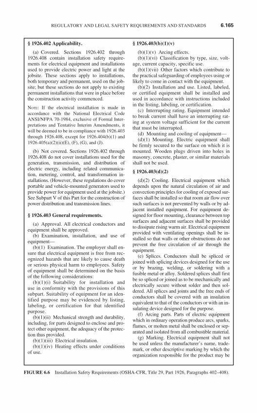
§ 1926.402 Applicability.
(a) Covered. Sections 1926.402 through1926.408 contain installation safety require-ments for electrical equipment and installationsused to provide electric power and light at thejobsite. These sections apply to installations,both temporary and permanent, used on the job-site; but these sections do not apply to existingpermanent installations that were in place beforethe construction activity commenced.
NOTE: If the electrical installation is made inaccordance with the National Electrical CodeANSI/NFPA 70-1984, exclusive of Formal Inter-pretations and Tentative Interim Amendments, itwill be deemed to be in compliance with 1926.403through 1926.408, except for 1926.404(b)(1) and1926.405(a)(2)(ii)(E), (F), (G), and (J).
(b) Not covered. Sections 1926.402 through1926.408 do not cover installations used for thegeneration, transmission, and distribution ofelectric energy, including related communica-tion, metering, control, and transformation in-stallations. (However, these regulations do coverportable and vehicle-mounted generators used toprovide power for equipment used at the jobsite.)See Subpart V of this Part for the construction ofpower distribution and transmission lines.
§ 1926.403 General requirements.
(a) Approval. All electrical conductors andequipment shall be approved.
(b) Examination, installation, and use ofequipment—
(b)(1) Examination. The employer shall en-sure that electrical equipment is free from rec-ognized hazards that are likely to cause deathor serious physical harm to employees. Safetyof equipment shall be determined on the basisof the following considerations:
(b)(1)(i) Suitability for installation anduse in conformity with the provisions of thissubpart. Suitability of equipment for an iden-tified purpose may be evidenced by listing,labeling, or certification for that identifiedpurpose.
(b)(1)(ii) Mechanical strength and durability,including, for parts designed to enclose and pro-tect other equipment, the adequacy of the protec-tion thus provided.
(b)(1)(iii) Electrical insulation.(b)(1)(iv) Heating effects under conditions
of use.
§ 1926.403(b)(1)(v)
(b)(1)(v) Arcing effects.(b)(1)(vi) Classification by type, size, volt-
age, current capacity, specific use.(b)(1)(vii) Other factors which contribute to
the practical safeguarding of employees using orlikely to come in contact with the equipment.
(b)(2) Installation and use. Listed, labeled,or certified equipment shall be installed andused in accordance with instructions includedin the listing, labeling, or certification.
(c) Interrupting rating. Equipment intendedto break current shall have an interrupting rat-ing at system voltage sufficient for the currentthat must be interrupted.
(d) Mounting and cooling of equipment—(d)(1) Mounting. Electric equipment shall
be firmly secured to the surface on which it ismounted. Wooden plugs driven into holes inmasonry, concrete, plaster, or similar materialsshall not be used.
§ 1926.403(d)(2)
(d)(2) Cooling. Electrical equipment whichdepends upon the natural circulation of air andconvection principles for cooling of exposed sur-faces shall be installed so that room air flow oversuch surfaces is not prevented by walls or by ad-jacent installed equipment. For equipment de-signed for floor mounting, clearance between topsurfaces and adjacent surfaces shall be providedto dissipate rising warm air. Electrical equipmentprovided with ventilating openings shall be in-stalled so that walls or other obstructions do notprevent the free circulation of air through theequipment.
(e) Splices. Conductors shall be spliced orjoined with splicing devices designed for the useor by brazing, welding, or soldering with afusible metal or alloy. Soldered splices shall firstbe so spliced or joined as to be mechanically andelectrically secure without solder and then sol-dered. All splices and joints and the free ends ofconductors shall be covered with an insulationequivalent to that of the conductors or with an in-sulating device designed for the purpose.
(f) Arcing parts. Parts of electric equipmentwhich in ordinary operation produce arcs, sparks,flames, or molten metal shall be enclosed or sep-arated and isolated from all combustible material.
(g) Marking. Electrical equipment shall notbe used unless the manufacturer’s name, trade-mark, or other descriptive marking by which theorganization responsible for the product may be
REGULATORY AND LEGAL SAFETY REQUIREMENTS AND STANDARDS 6.165
FIGURE 6.6 Installation Safety Requirements (OSHA-CFR, Title 29, Part 1926, Paragraphs 402–408).
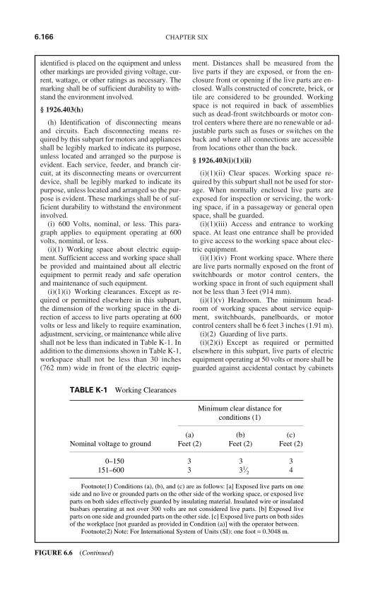
identified is placed on the equipment and unlessother markings are provided giving voltage, cur-rent, wattage, or other ratings as necessary. Themarking shall be of sufficient durability to with-stand the environment involved.
§ 1926.403(h)
(h) Identification of disconnecting meansand circuits. Each disconnecting means re-quired by this subpart for motors and appliancesshall be legibly marked to indicate its purpose,unless located and arranged so the purpose isevident. Each service, feeder, and branch cir-cuit, at its disconnecting means or overcurrentdevice, shall be legibly marked to indicate itspurpose, unless located and arranged so the pur-pose is evident. These markings shall be of suf-ficient durability to withstand the environmentinvolved.
(i) 600 Volts, nominal, or less. This para-graph applies to equipment operating at 600volts, nominal, or less.
(i)(1) Working space about electric equip-ment. Sufficient access and working space shallbe provided and maintained about all electricequipment to permit ready and safe operationand maintenance of such equipment.
(i)(1)(i) Working clearances. Except as re-quired or permitted elsewhere in this subpart,the dimension of the working space in the di-rection of access to live parts operating at 600volts or less and likely to require examination,adjustment, servicing, or maintenance while aliveshall not be less than indicated in Table K-1. Inaddition to the dimensions shown in Table K-1,workspace shall not be less than 30 inches(762 mm) wide in front of the electric equip-
ment. Distances shall be measured from thelive parts if they are exposed, or from the en-closure front or opening if the live parts are en-closed. Walls constructed of concrete, brick, ortile are considered to be grounded. Workingspace is not required in back of assembliessuch as dead-front switchboards or motor con-trol centers where there are no renewable or ad-justable parts such as fuses or switches on theback and where all connections are accessiblefrom locations other than the back.
§ 1926.403(i)(1)(ii)
(i)(1)(ii) Clear spaces. Working space re-quired by this subpart shall not be used for stor-age. When normally enclosed live parts areexposed for inspection or servicing, the work-ing space, if in a passageway or general openspace, shall be guarded.
(i)(1)(iii) Access and entrance to workingspace. At least one entrance shall be providedto give access to the working space about elec-tric equipment.
(i)(1)(iv) Front working space. Where thereare live parts normally exposed on the front ofswitchboards or motor control centers, theworking space in front of such equipment shallnot be less than 3 feet (914 mm).
(i)(1)(v) Headroom. The minimum head-room of working spaces about service equip-ment, switchboards, panelboards, or motorcontrol centers shall be 6 feet 3 inches (1.91 m).
(i)(2) Guarding of live parts.(i)(2)(i) Except as required or permitted
elsewhere in this subpart, live parts of electricequipment operating at 50 volts or more shall beguarded against accidental contact by cabinets
6.166 CHAPTER SIX
TABLE K-1 Working Clearances
Minimum clear distance forconditions (1)
(a) (b) (c)Nominal voltage to ground Feet (2) Feet (2) Feet (2)
0–150 3 3 3151–600 3 31⁄2 4
Footnote(1) Conditions (a), (b), and (c) are as follows: [a] Exposed live parts on oneside and no live or grounded parts on the other side of the working space, or exposed liveparts on both sides effectively guarded by insulating material. Insulated wire or insulatedbusbars operating at not over 300 volts are not considered live parts. [b] Exposed liveparts on one side and grounded parts on the other side. [c] Exposed live parts on both sidesof the workplace [not guarded as provided in Condition (a)] with the operator between.
Footnote(2) Note: For International System of Units (SI): one foot = 0.3048 m.
FIGURE 6.6 (Continued)
or other forms of enclosures, or by any of thefollowing means:
(i)(2)(i)(A) By location in a room, vault, orsimilar enclosure that is accessible only toqualified persons.
§ 1926.403(i)(2)(i)(B)
(i)(2)(i)(B) By partitions or screens soarranged that only qualified persons will haveaccess to the space within reach of the liveparts. Any openings in such partitions orscreens shall be so sized and located that per-sons are not likely to come into accidental con-tact with the live parts or to bring conductingobjects into contact with them.
(i)(2)(i)(C) By location on a balcony, gallery,or platform so elevated and arranged as to ex-clude unqualified persons.
(i)(2)(i)(D) By elevation of 8 feet (2.44 m) ormore above the floor or other working surface andso installed as to exclude unqualified persons.
(i)(2)(ii) In locations where electric equip-ment would be exposed to physical damage,enclosures or guards shall be so arranged andof such strength as to prevent such damage.
(i)(2)(iii) Entrances to rooms and other guardedlocations containing exposed live parts shall bemarked with conspicuous warning signs forbid-ding unqualified persons to enter.
(j) Over 600 volts, nominal.(j)(1) General. Conductors and equipment
used on circuits exceeding 600 volts, nominal,shall comply with all applicable provisions ofparagraphs (a) through (g) of this section andwith the following provisions which supple-ment or modify those requirements. The provi-sions of paragraphs (j)(2), (j)(3), and (j)(4) ofthis section do not apply to equipment on thesupply side of the service conductors.
§ 1926.403(j)(2)
(j)(2) Enclosure for electrical installations.Electrical installations in a vault, room, closet orin an area surrounded by a wall, screen, or fence,access to which is controlled by lock and key orother equivalent means, are considered to be ac-cessible to qualified persons only. A wall,screen, or fence less than 8 feet (2.44 m) inheight is not considered adequate to prevent ac-cess unless it has other features that provide adegree of isolation equivalent to an 8-foot (2.44-m) fence. The entrances to all buildings, roomsor enclosures containing exposed live parts orexposed conductors operating at over 600 volts,nominal, shall be kept locked or shall be underthe observation of a qualified person at all times.
(j)(2)(i) Installations accessible to qualified per-sons only. Electrical installations having exposedlive parts shall be accessible to qualified personsonly and shall comply with the applicable provi-sions of paragraph (j)(3) of this section.
(j)(2)(ii) Installations accessible to unqualifiedpersons. Electrical installations that are open tounqualified persons shall be made with metal-enclosed equipment or shall be enclosed in a vaultor in an area, access to which is controlled by alock. Metal-enclosed switchgear, unit substations,transformers, pull boxes, connection boxes, andother similar associated equipment shall bemarked with appropriate caution signs. If equip-ment is exposed to physical damage from vehicu-lar traffic, guards shall be provided to prevent suchdamage. Ventilating or similar openings in metal-enclosed equipment shall be designed so that for-eign objects inserted through these openings willbe deflected from energized parts.
§ 1926.403(j)(3)
(j)(3) Workspace about equipment. Suffi-cient space shall be provided and maintainedabout electric equipment to permit ready andsafe operation and maintenance of such equip-ment. Where energized parts are exposed, theminimum clear workspace shall not be less than6 feet 6 inches (1.98 m) high (measured verti-cally from the floor or platform), or less than 3feet (914 mm) wide (measured parallel to theequipment). The depth shall be as required inTable K-2. The workspace shall be adequate topermit at least a 90-degree opening of doors orhinged panels.
(j)(3)(i) Working space. The minimum clearworking space in front of electric equipmentsuch as switchboards, control panels, switches,circuit breakers, motor controllers, relays, andsimilar equipment shall not be less than speci-fied in Table K-2 unless otherwise specified inthis subpart. Distances shall be measured fromthe live parts if they are exposed, or from theenclosure front or opening if the live parts areenclosed. However, working space is not re-quired in back of equipment such as deadfrontswitchboards or control assemblies where thereare no renewable or adjustable parts (such asfuses or switches) on the back and where allconnections are accessible from locations otherthan the back. Where rear access is required towork on de-energized parts on the back of en-closed equipment, a minimum working spaceof 30 inches (762 mm) horizontally shall beprovided.
REGULATORY AND LEGAL SAFETY REQUIREMENTS AND STANDARDS 6.167
FIGURE 6.6 (Continued)
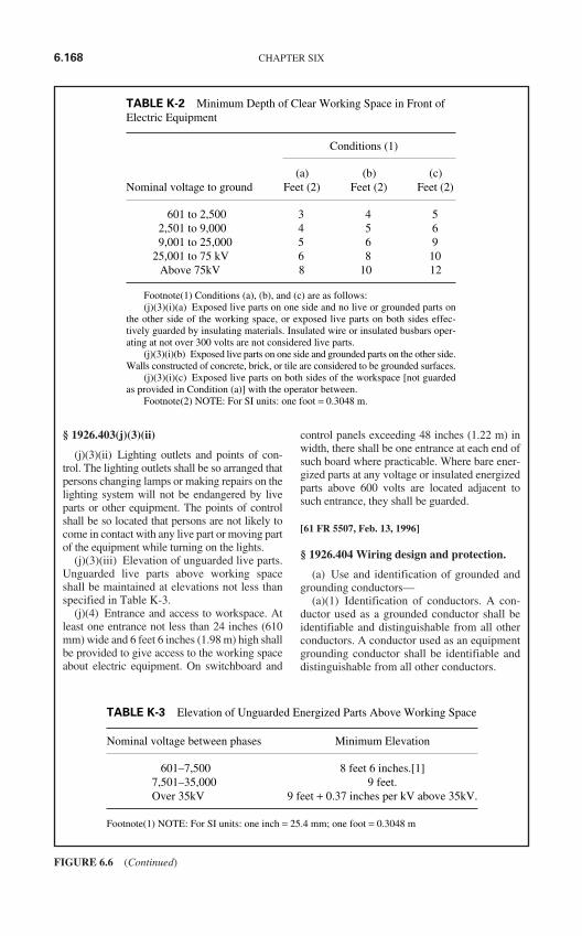
§ 1926.403(j)(3)(ii)
(j)(3)(ii) Lighting outlets and points of con-trol. The lighting outlets shall be so arranged thatpersons changing lamps or making repairs on thelighting system will not be endangered by liveparts or other equipment. The points of controlshall be so located that persons are not likely tocome in contact with any live part or moving partof the equipment while turning on the lights.
(j)(3)(iii) Elevation of unguarded live parts.Unguarded live parts above working spaceshall be maintained at elevations not less thanspecified in Table K-3.
(j)(4) Entrance and access to workspace. Atleast one entrance not less than 24 inches (610mm) wide and 6 feet 6 inches (1.98 m) high shallbe provided to give access to the working spaceabout electric equipment. On switchboard and
control panels exceeding 48 inches (1.22 m) inwidth, there shall be one entrance at each end ofsuch board where practicable. Where bare ener-gized parts at any voltage or insulated energizedparts above 600 volts are located adjacent tosuch entrance, they shall be guarded.
[61 FR 5507, Feb. 13, 1996]
§ 1926.404 Wiring design and protection.
(a) Use and identification of grounded andgrounding conductors—
(a)(1) Identification of conductors. A con-ductor used as a grounded conductor shall beidentifiable and distinguishable from all otherconductors. A conductor used as an equipmentgrounding conductor shall be identifiable anddistinguishable from all other conductors.
6.168 CHAPTER SIX
FIGURE 6.6 (Continued)
TABLE K-2 Minimum Depth of Clear Working Space in Front ofElectric Equipment
Conditions (1)
(a) (b) (c)Nominal voltage to ground Feet (2) Feet (2) Feet (2)
601 to 2,500 3 4 52,501 to 9,000 4 5 69,001 to 25,000 5 6 9
25,001 to 75 kV 6 8 10Above 75kV 8 10 12
Footnote(1) Conditions (a), (b), and (c) are as follows:(j)(3)(i)(a) Exposed live parts on one side and no live or grounded parts on
the other side of the working space, or exposed live parts on both sides effec-tively guarded by insulating materials. Insulated wire or insulated busbars oper-ating at not over 300 volts are not considered live parts.
(j)(3)(i)(b) Exposed live parts on one side and grounded parts on the other side.Walls constructed of concrete, brick, or tile are considered to be grounded surfaces.
(j)(3)(i)(c) Exposed live parts on both sides of the workspace [not guardedas provided in Condition (a)] with the operator between.
Footnote(2) NOTE: For SI units: one foot = 0.3048 m.
TABLE K-3 Elevation of Unguarded Energized Parts Above Working Space
Nominal voltage between phases Minimum Elevation
601–7,500 8 feet 6 inches.[1]7,501–35,000 9 feet.Over 35kV 9 feet + 0.37 inches per kV above 35kV.
Footnote(1) NOTE: For SI units: one inch = 25.4 mm; one foot = 0.3048 m
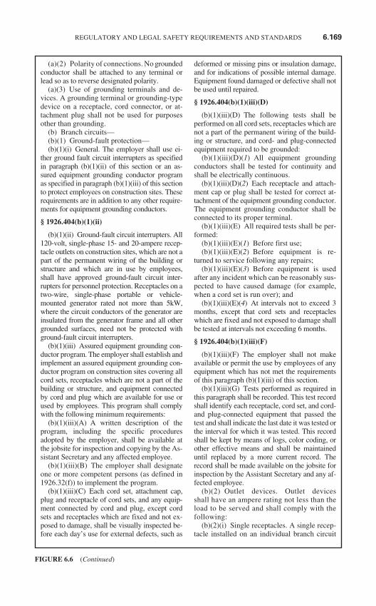
(a)(2) Polarity of connections. No groundedconductor shall be attached to any terminal orlead so as to reverse designated polarity.
(a)(3) Use of grounding terminals and de-vices. A grounding terminal or grounding-typedevice on a receptacle, cord connector, or at-tachment plug shall not be used for purposesother than grounding.
(b) Branch circuits—(b)(1) Ground-fault protection—(b)(1)(i) General. The employer shall use ei-
ther ground fault circuit interrupters as specifiedin paragraph (b)(1)(ii) of this section or an as-sured equipment grounding conductor programas specified in paragraph (b)(1)(iii) of this sectionto protect employees on construction sites. Theserequirements are in addition to any other require-ments for equipment grounding conductors.
§ 1926.404(b)(1)(ii)
(b)(1)(ii) Ground-fault circuit interrupters. All120-volt, single-phase 15- and 20-ampere recep-tacle outlets on construction sites, which are not apart of the permanent wiring of the building orstructure and which are in use by employees,shall have approved ground-fault circuit inter-rupters for personnel protection. Receptacles on atwo-wire, single-phase portable or vehicle-mounted generator rated not more than 5kW,where the circuit conductors of the generator areinsulated from the generator frame and all othergrounded surfaces, need not be protected withground-fault circuit interrupters.
(b)(1)(iii) Assured equipment grounding con-ductor program. The employer shall establish andimplement an assured equipment grounding con-ductor program on construction sites covering allcord sets, receptacles which are not a part of thebuilding or structure, and equipment connectedby cord and plug which are available for use orused by employees. This program shall complywith the following minimum requirements:
(b)(1)(iii)(A) A written description of theprogram, including the specific proceduresadopted by the employer, shall be available atthe jobsite for inspection and copying by the As-sistant Secretary and any affected employee.
(b)(1)(iii)(B) The employer shall designateone or more competent persons (as defined in1926.32(f)) to implement the program.
(b)(1)(iii)(C) Each cord set, attachment cap,plug and receptacle of cord sets, and any equip-ment connected by cord and plug, except cordsets and receptacles which are fixed and not ex-posed to damage, shall be visually inspected be-fore each day’s use for external defects, such as
deformed or missing pins or insulation damage,and for indications of possible internal damage.Equipment found damaged or defective shall notbe used until repaired.
§ 1926.404(b)(1)(iii)(D)
(b)(1)(iii)(D) The following tests shall beperformed on all cord sets, receptacles which arenot a part of the permanent wiring of the build-ing or structure, and cord- and plug-connectedequipment required to be grounded:
(b)(1)(iii)(D)(1) All equipment groundingconductors shall be tested for continuity andshall be electrically continuous.
(b)(1)(iii)(D)(2) Each receptacle and attach-ment cap or plug shall be tested for correct at-tachment of the equipment grounding conductor.The equipment grounding conductor shall beconnected to its proper terminal.
(b)(1)(iii)(E) All required tests shall be per-formed:
(b)(1)(iii)(E)(1) Before first use;(b)(1)(iii)(E)(2) Before equipment is re-
turned to service following any repairs;(b)(1)(iii)(E)(3) Before equipment is used
after any incident which can be reasonably sus-pected to have caused damage (for example,when a cord set is run over); and
(b)(1)(iii)(E)(4) At intervals not to exceed 3months, except that cord sets and receptacleswhich are fixed and not exposed to damage shallbe tested at intervals not exceeding 6 months.
§ 1926.404(b)(1)(iii)(F)
(b)(1)(iii)(F) The employer shall not makeavailable or permit the use by employees of anyequipment which has not met the requirementsof this paragraph (b)(1)(iii) of this section.
(b)(1)(iii)(G) Tests performed as required inthis paragraph shall be recorded. This test recordshall identify each receptacle, cord set, and cord-and plug-connected equipment that passed thetest and shall indicate the last date it was tested orthe interval for which it was tested. This recordshall be kept by means of logs, color coding, orother effective means and shall be maintaineduntil replaced by a more current record. Therecord shall be made available on the jobsite forinspection by the Assistant Secretary and any af-fected employee.
(b)(2) Outlet devices. Outlet devicesshall have an ampere rating not less than theload to be served and shall comply with thefollowing:
(b)(2)(i) Single receptacles. A single recep-tacle installed on an individual branch circuit
REGULATORY AND LEGAL SAFETY REQUIREMENTS AND STANDARDS 6.169
FIGURE 6.6 (Continued)
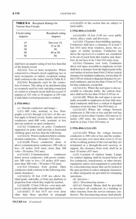
shall have an ampere rating of not less than thatof the branch circuit.
(b)(2)(ii) Two or more receptacles. Whereconnected to a branch circuit supplying two ormore receptacles or outlets, receptacle ratingsshall conform to the values listed in Table K-4.
(b)(2)(iii) Receptacles used for the connec-tion of motors. The rating of an attachment plugor receptacle used for cord- and plug-connectionof a motor to a branch circuit shall not exceed 15amperes at 125 volts or 10 amperes at 250 voltsif individual overload protection is omitted.
§ 1926.404(c)
(c) Outside conductors and lamps—(c)(1) 600 volts, nominal, or less. Para-
graphs (c)(1)(i) through (c)(1)(iv) of this sec-tion apply to branch circuit, feeder, and serviceconductors rated 600 volts, nominal, or lessand run outdoors as open conductors.
(c)(1)(i) Conductors on poles. Conductorssupported on poles shall provide a horizontalclimbing space not less than the following:
(c)(1)(i)(A) Powerconductorsbelowcommu-nication conductors—30 inches (762 mm).
(c)(1)(i)(B) Power conductors alone orabove communication conductors: 300 volts orless—24 inches (610 mm); more than 300volts—30 inches (762 mm).
(c)(1)(i)(C) Communication conductorsbelow power conductors: with power conduc-tors 300 volts or less—24 inches (610 mm);more than 300 volts—30 inches (762 mm).
(c)(1)(ii) Clearance from ground. Openconductors shall conform to the following min-imum clearances:
(c)(1)(ii)(A) 10 feet (3.05 m)—above fin-ished grade, sidewalks, or from any platform orprojection from which they might be reached.
(c)(1)(ii)(B) 12 feet (3.66 m)—over areas sub-ject to vehicular traffic other than truck traffic.
(c)(1)(ii)(C) 15 feet (4.57 m)—over areasother than those specified in paragraph
(c)(1)(ii)(D) of this section that are subject totruck traffic.
§ 1926.404(c)(1)(ii)(D)
(c)(1)(ii)(D) 18 feet (5.49 m)—over publicstreets, alleys, roads, and driveways.
(c)(1)(iii) Clearance from building openings.Conductors shall have a clearance of at least 3feet (914 mm) from windows, doors, fire es-capes, or similar locations. Conductors runabove the top level of a window are consideredto be out of reach from that window and, there-fore, do not have to be 3 feet (914 mm) away.
(c)(1)(iv) Clearance over roofs. Conductorsabove roof space accessible to employees on footshall have a clearance from the highest point of theroof surface of not less than 8 feet (2.44 m) verticalclearance for insulated conductors, not less than 10feet (3.05 m) vertical or diagonal clearance for cov-ered conductors, and not less than 15 feet (4.57 m)for bare conductors, except that:
(c)(1)(iv)(A) Where the roof space is also ac-cessible to vehicular traffic, the vertical clear-ance shall not be less than 18 feet (5.49 m), or
(c)(1)(iv)(B) Where the roof space is not nor-mally accessible to employees on foot, fully insu-lated conductors shall have a vertical or diagonalclearance of not less than 3 feet (914 mm), or
(c)(1)(iv)(C) Where the voltage betweenconductors is 300 volts or less and the roof hasa slope of not less than 4 inches (102 mm) in 12inches (305 mm), the clearance from roofsshall be at least 3 feet (914 mm), or
§ 1926.404(c)(1)(iv)(D)
(c)(1)(iv)(D) Where the voltage betweenconductors is 300 volts or less and the conduc-tors do not pass over more than 4 feet (1.22 m)of the overhang portion of the roof and they areterminated at a through-the-roof raceway orsupport, the clearance from roofs shall be atleast 18 inches (457 mm).
(c)(2) Location of outdoor lamps. Lampsfor outdoor lighting shall be located below alllive conductors, transformers, or other electricequipment, unless such equipment is controlledby a disconnecting means that can be locked inthe open position or unless adequate clearancesor other safeguards are provided for relampingoperations.
(d) Services—(d)(1) Disconnecting means—(d)(1)(i) General. Means shall be provided
to disconnect all conductors in a building orother structure from the service-entrance con-ductors. The disconnecting means shall plainly
6.170 CHAPTER SIX
FIGURE 6.6 (Continued)
TABLE K-4 Receptacle Ratings forVarious Size Circuits
Circuit rating Receptacle rating amperes amperes
15 Not over 15.20 15 or 20.30 30.40 40 or 50.50 50.
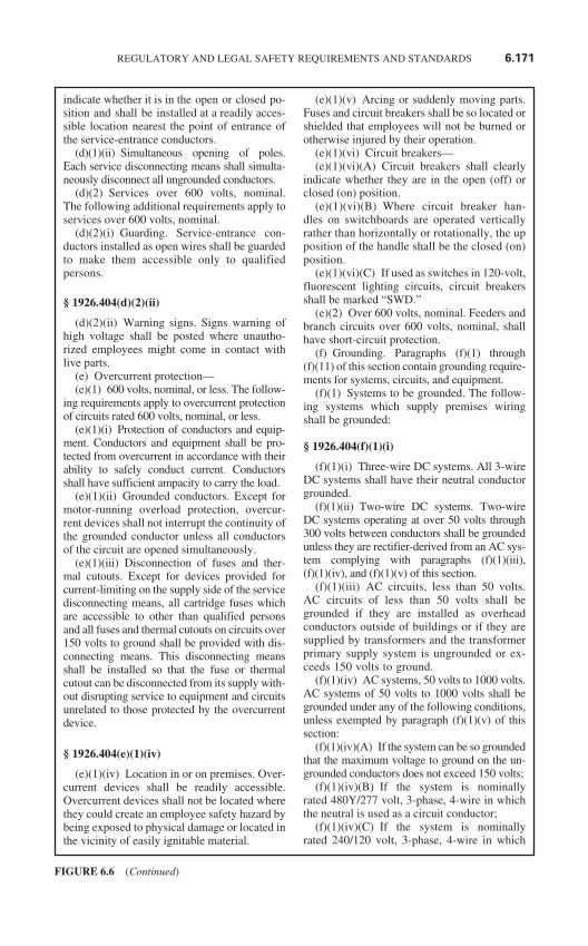
indicate whether it is in the open or closed po-sition and shall be installed at a readily acces-sible location nearest the point of entrance ofthe service-entrance conductors.
(d)(1)(ii) Simultaneous opening of poles.Each service disconnecting means shall simulta-neously disconnect all ungrounded conductors.
(d)(2) Services over 600 volts, nominal.The following additional requirements apply toservices over 600 volts, nominal.
(d)(2)(i) Guarding. Service-entrance con-ductors installed as open wires shall be guardedto make them accessible only to qualifiedpersons.
§ 1926.404(d)(2)(ii)
(d)(2)(ii) Warning signs. Signs warning ofhigh voltage shall be posted where unautho-rized employees might come in contact withlive parts.
(e) Overcurrent protection—(e)(1) 600 volts, nominal, or less. The follow-
ing requirements apply to overcurrent protectionof circuits rated 600 volts, nominal, or less.
(e)(1)(i) Protection of conductors and equip-ment. Conductors and equipment shall be pro-tected from overcurrent in accordance with theirability to safely conduct current. Conductorsshall have sufficient ampacity to carry the load.
(e)(1)(ii) Grounded conductors. Except formotor-running overload protection, overcur-rent devices shall not interrupt the continuity ofthe grounded conductor unless all conductorsof the circuit are opened simultaneously.
(e)(1)(iii) Disconnection of fuses and ther-mal cutouts. Except for devices provided forcurrent-limiting on the supply side of the servicedisconnecting means, all cartridge fuses whichare accessible to other than qualified personsand all fuses and thermal cutouts on circuits over150 volts to ground shall be provided with dis-connecting means. This disconnecting meansshall be installed so that the fuse or thermalcutout can be disconnected from its supply with-out disrupting service to equipment and circuitsunrelated to those protected by the overcurrentdevice.
§ 1926.404(e)(1)(iv)
(e)(1)(iv) Location in or on premises. Over-current devices shall be readily accessible.Overcurrent devices shall not be located wherethey could create an employee safety hazard bybeing exposed to physical damage or located inthe vicinity of easily ignitable material.
(e)(1)(v) Arcing or suddenly moving parts.Fuses and circuit breakers shall be so located orshielded that employees will not be burned orotherwise injured by their operation.
(e)(1)(vi) Circuit breakers—(e)(1)(vi)(A) Circuit breakers shall clearly
indicate whether they are in the open (off) orclosed (on) position.
(e)(1)(vi)(B) Where circuit breaker han-dles on switchboards are operated verticallyrather than horizontally or rotationally, the upposition of the handle shall be the closed (on)position.
(e)(1)(vi)(C) If used as switches in 120-volt,fluorescent lighting circuits, circuit breakersshall be marked “SWD.”
(e)(2) Over 600 volts, nominal. Feeders andbranch circuits over 600 volts, nominal, shallhave short-circuit protection.
(f) Grounding. Paragraphs (f)(1) through(f)(11) of this section contain grounding require-ments for systems, circuits, and equipment.
(f)(1) Systems to be grounded. The follow-ing systems which supply premises wiringshall be grounded:
§ 1926.404(f)(1)(i)
(f)(1)(i) Three-wire DC systems. All 3-wireDC systems shall have their neutral conductorgrounded.
(f)(1)(ii) Two-wire DC systems. Two-wireDC systems operating at over 50 volts through300 volts between conductors shall be groundedunless they are rectifier-derived from an AC sys-tem complying with paragraphs (f)(1)(iii),(f)(1)(iv), and (f)(1)(v) of this section.
(f)(1)(iii) AC circuits, less than 50 volts.AC circuits of less than 50 volts shall begrounded if they are installed as overheadconductors outside of buildings or if they aresupplied by transformers and the transformerprimary supply system is ungrounded or ex-ceeds 150 volts to ground.
(f)(1)(iv) AC systems, 50 volts to 1000 volts.AC systems of 50 volts to 1000 volts shall begrounded under any of the following conditions,unless exempted by paragraph (f)(1)(v) of thissection:
(f)(1)(iv)(A) If the system can be so groundedthat the maximum voltage to ground on the un-grounded conductors does not exceed 150 volts;
(f)(1)(iv)(B) If the system is nominallyrated 480Y/277 volt, 3-phase, 4-wire in whichthe neutral is used as a circuit conductor;
(f)(1)(iv)(C) If the system is nominallyrated 240/120 volt, 3-phase, 4-wire in which
REGULATORY AND LEGAL SAFETY REQUIREMENTS AND STANDARDS 6.171
FIGURE 6.6 (Continued)
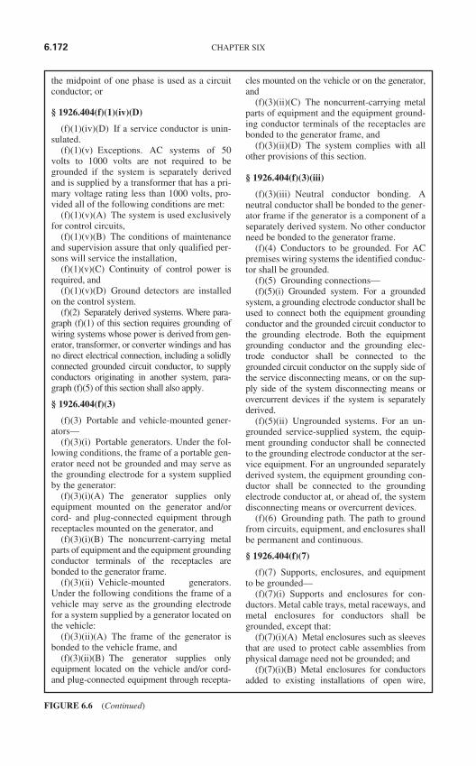
the midpoint of one phase is used as a circuitconductor; or
§ 1926.404(f)(1)(iv)(D)
(f)(1)(iv)(D) If a service conductor is unin-sulated.
(f)(1)(v) Exceptions. AC systems of 50volts to 1000 volts are not required to begrounded if the system is separately derivedand is supplied by a transformer that has a pri-mary voltage rating less than 1000 volts, pro-vided all of the following conditions are met:
(f)(1)(v)(A) The system is used exclusivelyfor control circuits,
(f)(1)(v)(B) The conditions of maintenanceand supervision assure that only qualified per-sons will service the installation,
(f)(1)(v)(C) Continuity of control power isrequired, and
(f)(1)(v)(D) Ground detectors are installedon the control system.
(f)(2) Separately derived systems. Where para-graph (f)(1) of this section requires grounding ofwiring systems whose power is derived from gen-erator, transformer, or converter windings and hasno direct electrical connection, including a solidlyconnected grounded circuit conductor, to supplyconductors originating in another system, para-graph (f)(5) of this section shall also apply.
§ 1926.404(f)(3)
(f)(3) Portable and vehicle-mounted gener-ators—
(f)(3)(i) Portable generators. Under the fol-lowing conditions, the frame of a portable gen-erator need not be grounded and may serve asthe grounding electrode for a system suppliedby the generator:
(f)(3)(i)(A) The generator supplies onlyequipment mounted on the generator and/orcord- and plug-connected equipment throughreceptacles mounted on the generator, and
(f)(3)(i)(B) The noncurrent-carrying metalparts of equipment and the equipment groundingconductor terminals of the receptacles arebonded to the generator frame.
(f)(3)(ii) Vehicle-mounted generators.Under the following conditions the frame of avehicle may serve as the grounding electrodefor a system supplied by a generator located onthe vehicle:
(f)(3)(ii)(A) The frame of the generator isbonded to the vehicle frame, and
(f)(3)(ii)(B) The generator supplies onlyequipment located on the vehicle and/or cord-and plug-connected equipment through recepta-
cles mounted on the vehicle or on the generator,and
(f)(3)(ii)(C) The noncurrent-carrying metalparts of equipment and the equipment ground-ing conductor terminals of the receptacles arebonded to the generator frame, and
(f)(3)(ii)(D) The system complies with allother provisions of this section.
§ 1926.404(f)(3)(iii)
(f)(3)(iii) Neutral conductor bonding. Aneutral conductor shall be bonded to the gener-ator frame if the generator is a component of aseparately derived system. No other conductorneed be bonded to the generator frame.
(f)(4) Conductors to be grounded. For ACpremises wiring systems the identified conduc-tor shall be grounded.
(f)(5) Grounding connections—(f)(5)(i) Grounded system. For a grounded
system, a grounding electrode conductor shall beused to connect both the equipment groundingconductor and the grounded circuit conductor tothe grounding electrode. Both the equipmentgrounding conductor and the grounding elec-trode conductor shall be connected to thegrounded circuit conductor on the supply side ofthe service disconnecting means, or on the sup-ply side of the system disconnecting means orovercurrent devices if the system is separatelyderived.
(f)(5)(ii) Ungrounded systems. For an un-grounded service-supplied system, the equip-ment grounding conductor shall be connectedto the grounding electrode conductor at the ser-vice equipment. For an ungrounded separatelyderived system, the equipment grounding con-ductor shall be connected to the groundingelectrode conductor at, or ahead of, the systemdisconnecting means or overcurrent devices.
(f)(6) Grounding path. The path to groundfrom circuits, equipment, and enclosures shallbe permanent and continuous.
§ 1926.404(f)(7)
(f)(7) Supports, enclosures, and equipmentto be grounded—
(f)(7)(i) Supports and enclosures for con-ductors. Metal cable trays, metal raceways, andmetal enclosures for conductors shall begrounded, except that:
(f)(7)(i)(A) Metal enclosures such as sleevesthat are used to protect cable assemblies fromphysical damage need not be grounded; and
(f)(7)(i)(B) Metal enclosures for conductorsadded to existing installations of open wire,
6.172 CHAPTER SIX
FIGURE 6.6 (Continued)
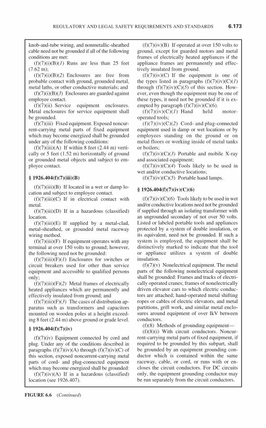
knob-and-tube wiring, and nonmetallic-sheathedcable need not be grounded if all of the followingconditions are met:
(f)(7)(i)(B)(1) Runs are less than 25 feet(7.62 m);
(f)(7)(i)(B)(2) Enclosures are free fromprobable contact with ground, grounded metal,metal laths, or other conductive materials; and
(f)(7)(i)(B)(3) Enclosures are guarded againstemployee contact.
(f)(7)(ii) Service equipment enclosures.Metal enclosures for service equipment shallbe grounded.
(f)(7)(iii) Fixed equipment. Exposed noncur-rent-carrying metal parts of fixed equipmentwhich may become energized shall be groundedunder any of the following conditions:
(f)(7)(iii)(A) If within 8 feet (2.44 m) verti-cally or 5 feet (1.52 m) horizontally of groundor grounded metal objects and subject to em-ployee contact.
§ 1926.404(f)(7)(iii)(B)
(f)(7)(iii)(B) If located in a wet or damp lo-cation and subject to employee contact.
(f)(7)(iii)(C) If in electrical contact withmetal.
(f)(7)(iii)(D) If in a hazardous (classified)location.
(f)(7)(iii)(E) If supplied by a metal-clad,metal-sheathed, or grounded metal racewaywiring method.
(f)(7)(iii)(F) If equipment operates with anyterminal at over 150 volts to ground; however,the following need not be grounded:
(f)(7)(iii)(F)(1) Enclosures for switches orcircuit breakers used for other than serviceequipment and accessible to qualified personsonly;
(f)(7)(iii)(F)(2) Metal frames of electricallyheated appliances which are permanently andeffectively insulated from ground; and
(f)(7)(iii)(F)(3) The cases of distribution ap-paratus such as transformers and capacitorsmounted on wooden poles at a height exceed-ing 8 feet (2.44 m) above ground or grade level.
§ 1926.404(f)(7)(iv)
(f)(7)(iv) Equipment connected by cord andplug. Under any of the conditions described inparagraphs (f)(7)(iv)(A) through (f)(7)(iv)(C) ofthis section, exposed noncurrent-carrying metalparts of cord- and plug-connected equipmentwhich may become energized shall be grounded:
(f)(7)(iv)(A) If in a hazardous (classified)location (see 1926.407).
(f)(7)(iv)(B) If operated at over 150 volts toground, except for guarded motors and metalframes of electrically heated appliances if theappliance frames are permanently and effec-tively insulated from ground.
(f)(7)(iv)(C) If the equipment is one ofthe types listed in paragraphs (f)(7)(iv)(C)(1)through (f)(7)(iv)(C)(5) of this section. How-ever, even though the equipment may be one ofthese types, it need not be grounded if it is ex-empted by paragraph (f)(7)(iv)(C)(6).
(f)(7)(iv)(C)(1) Hand held motor-operated tools;
(f)(7)(iv)(C)(2) Cord- and plug-connectedequipment used in damp or wet locations or byemployees standing on the ground or onmetal floors or working inside of metal tanksor boilers;
(f)(7)(iv)(C)(3) Portable and mobile X-rayand associated equipment;
(f)(7)(iv)(C)(4) Tools likely to be used inwet and/or conductive locations;
(f)(7)(iv)(C)(5) Portable hand lamps.
§ 1926.404(f)(7)(iv)(C)(6)
(f)(7)(iv)(C)(6) Tools likely to be used in wetand/or conductive locations need not be groundedif supplied through an isolating transformer withan ungrounded secondary of not over 50 volts.Listed or labeled portable tools and appliancesprotected by a system of double insulation, orits equivalent, need not be grounded. If such asystem is employed, the equipment shall bedistinctively marked to indicate that the toolor appliance utilizes a system of doubleinsulation.
(f)(7)(v) Nonelectrical equipment. The metalparts of the following nonelectrical equipmentshall be grounded: Frames and tracks of electri-cally operated cranes; frames of nonelectricallydriven elevator cars to which electric conduc-tors are attached; hand-operated metal shiftingropes or cables of electric elevators, and metalpartitions, grill work, and similar metal enclo-sures around equipment of over IkV betweenconductors.
(f)(8) Methods of grounding equipment—(f)(8)(i) With circuit conductors. Noncur-
rent-carrying metal parts of fixed equipment, ifrequired to be grounded by this subpart, shallbe grounded by an equipment grounding con-ductor which is contained within the sameraceway, cable, or cord, or runs with or en-closes the circuit conductors. For DC circuitsonly, the equipment grounding conductor maybe run separately from the circuit conductors.
REGULATORY AND LEGAL SAFETY REQUIREMENTS AND STANDARDS 6.173
FIGURE 6.6 (Continued)
(f)(8)(ii) Grounding conductor. A conductorused for grounding fixed or movable equipmentshall have capacity to conduct safely any faultcurrent which may be imposed on it.
§ 1926.404(f)(8)(iii)
(f)(8)(iii) Equipment considered effectivelygrounded. Electric equipment is considered to beeffectively grounded if it is secured to, and inelectrical contact with, a metal rack or structurethat is provided for its support and the metal rackor structure is grounded by the method specifiedfor the noncurrent-carrying metal parts of fixedequipment in paragraph (f)(8)(i) of this section.Metal car frames supported by metal hoisting ca-bles attached to or running over metal sheaves ordrums of grounded elevator machines are alsoconsidered to be effectively grounded.
(f)(9) Bonding. If bonding conductors areused to assure electrical continuity, they shallhave the capacity to conduct any fault currentwhich may be imposed.
(f)(10) Made electrodes. If made electrodesare used, they shall be free from nonconductivecoatings, such as paint or enamel; and, if practi-cable, they shall be embedded below permanentmoisture level. A single electrode consisting of arod, pipe or plate which has a resistance toground greater than 25 ohms shall be augmentedby one additional electrode installed no closerthan 6 feet (1.83 m) to the first electrode.
(f)(11) Grounding of systems and circuits of1000 volts and over (high voltage)—
(f)(11)(i) General. If high voltage systemsare grounded, they shall comply with all ap-plicable provisions of paragraphs (f)(1)through (f)(10) of this section as supplementedand modified by this paragraph (f)(11).
(f)(11)(ii) Grounding of systems supplyingportable or mobile equipment. Systems supply-ing portable or mobile high voltage equipment,other than substations installed on a temporarybasis, shall comply with the following:
§ 1926.404(f)(11)(ii)(A)
(f)(11)(ii)(A) Portable and mobile highvoltage equipment shall be supplied from asystem having its neutral grounded through animpedance. If a delta-connected high voltagesystem is used to supply the equipment, a sys-tem neutral shall be derived.
(f)(11)(ii)(B) Exposed noncurrent-carryingmetal parts of portable and mobile equipmentshall be connected by an equipment groundingconductor to the point at which the system neu-tral impedance is grounded.
(f)(11)(ii)(C) Ground-fault detection andrelaying shall be provided to automatically de-energize any high voltage system componentwhich has developed a ground fault. The conti-nuity of the equipment grounding conductorshall be continuously monitored so as to de-energize automatically the high voltage feederto the portable equipment upon loss of continu-ity of the equipment grounding conductor.
(f)(11)(ii)(D) The grounding electrode towhich the portable or mobile equipment sys-tem neutral impedance is connected shall beisolated from and separated in the ground by atleast 20 feet (6.1 m) from any other system orequipment grounding electrode, and there shallbe no direct connection between the groundingelectrodes, such as buried pipe, fence or likeobjects.
§ 1926.404(f)(11)(iii)
(f)(11)(iii) Grounding of equipment. All non-current-carrying metal parts of portable equip-ment and fixed equipment including theirassociated fences, housings, enclosures, and sup-porting structures shall be grounded. However,equipment which is guarded by location and iso-lated from ground need not be grounded. Addi-tionally, pole-mounted distribution apparatus at aheight exceeding 8 feet (2.44 m) above ground orgrade level need not be grounded.
[54 FR 24334, June 7, 1989; 61 FR 5507, Feb. 13,1996]
§ 1926.405 Wiring methods, components,and equipment for general use.
(a) Wiring methods. The provisions of thisparagraph do not apply to conductors whichform an integral part of equipment such as mo-tors, controllers, motor control centers and likeequipment.
(a)(1) General requirements—(a)(1)(i) Electrical continuity of metal race-
ways and enclosures. Metal raceways, cablearmor, and other metal enclosures for conduc-tors shall be metallically joined together into acontinuous electric conductor and shall be soconnected to all boxes, fittings, and cabinets asto provide effective electrical continuity.
(a)(1)(ii) Wiring in ducts. No wiring sys-tems of any type shall be installed in ducts usedto transport dust, loose stock or flammable va-pors. No wiring system of any type shall be in-stalled in any duct used for vapor removal or inany shaft containing only such ducts.
6.174 CHAPTER SIX
FIGURE 6.6 (Continued)
§ 1926.405(a)(2)
(a)(2) Temporary wiring—(a)(2)(i) Scope. The provisions of paragraph
(a)(2) of this section apply to temporary electri-cal power and lighting wiring methods whichmay be of a class less than would be required fora permanent installation. Except as specificallymodified in paragraph (a)(2) of this section, allother requirements of this subpart for permanentwiring shall apply to temporary wiring installa-tions. Temporary wiring shall be removed imme-diately upon completion of construction or thepurpose for which the wiring was installed.
(a)(2)(ii) General requirements for tempo-rary wiring—
(a)(2)(ii)(A) Feeders shall originate in a distri-bution center. The conductors shall be run as mul-ticonductor cord or cable assemblies or withinraceways; or, where not subject to physical dam-age, they may be run as open conductors on insu-lators not more than 10 feet (3.05 m) apart.
(a)(2)(ii)(B) Branch circuits shall originate ina power outlet or panelboard. Conductors shallbe run as multiconductor cord or cable assem-blies or open conductors, or shall be run in race-ways. All conductors shall be protected byovercurrent devices at their ampacity. Runs ofopen conductors shall be located where the con-ductors will not be subject to physical damage,and the conductors shall be fastened at intervalsnot exceeding 10 feet (3.05 m). No branch-circuit conductors shall be laid on the floor. Eachbranch circuit that supplies receptacles or fixedequipment shall contain a separate equipmentgrounding conductor if the branch circuit is runas open conductors.
§ 1926.405(a)(2)(ii)(C)
(a)(2)(ii)(C) Receptacles shall be of thegrounding type. Unless installed in a completemetallic raceway, each branch circuit shallcontain a separate equipment grounding con-ductor, and all receptacles shall be electricallyconnected to the grounding conductor. Recep-tacles for uses other than temporary lightingshall not be installed on branch circuits whichsupply temporary lighting. Receptacles shallnot be connected to the same ungrounded con-ductor of multiwire circuits which supply tem-porary lighting.
(a)(2)(ii)(D) Disconnecting switches orplug connectors shall be installed to permit thedisconnection of all ungrounded conductors ofeach temporary circuit.
(a)(2)(ii)(E) All lamps for general illumina-tion shall be protected from accidental contact
or breakage. Metal-case sockets shall begrounded.
(a)(2)(ii)(F) Temporary lights shall not besuspended by their electric cords unlesscords and lights are designed for this meansof suspension.
(a)(2)(ii)(G) Portable electric lighting usedin wet and/or other conductive locations, as forexample, drums, tanks, and vessels, shall beoperated at 12 volts or less. However, 120-voltlights may be used if protected by a ground-fault circuit interrupter.
(a)(2)(ii)(H) A box shall be used wherever achange is made to a raceway system or a cablesystem which is metal clad or metal sheathed.
(a)(2)(ii)(I) Flexible cords and cables shall beprotected from damage. Sharp corners and pro-jections shall be avoided. Flexible cords and ca-bles may pass through doorways or other pinchpoints, if protection is provided to avoid damage.
§ 1926.405(a)(2)(ii)(J)
(a)(2)(ii)(J) Extension cord sets used withportable electric tools and appliances shall beof three-wire type and shall be designed forhard or extra-hard usage. Flexible cords usedwith temporary and portable lights shall be de-signed for hard or extra-hard usage.
NOTE: The National Electrical Code, ANSI/NFPA 70, in Article 400, Table 400-4, lists varioustypes of flexible cords, some of which are noted asbeing designed for hard or extra-hard usage. Exam-ples of these types of flexible cords include hard ser-vice cord (types S, ST, SO, STO) and junior hardservice cord (types SJ, SJO, SJT, SJTO).
(a)(2)(iii) Guarding. For temporary wiringover 600 volts, nominal, fencing, barriers, orother effective means shall be provided to pre-vent access of other than authorized and quali-fied personnel.
(b) Cabinets, boxes, and fittings.(b)(1) Conductors entering boxes, cabinets,
or fittings. Conductors entering boxes, cabi-nets, or fittings shall be protected from abra-sion, and openings through which conductorsenter shall be effectively closed. Unused open-ings in cabinets, boxes, and fittings shall alsobe effectively closed.
(b)(2) Covers and canopies. All pull boxes,junction boxes, and fittings shall be providedwith covers. If metal covers are used, they shallbe grounded. In energized installations eachoutlet box shall have a cover, faceplate, or fix-ture canopy. Covers of outlet boxes havingholes through which flexible cord pendants
REGULATORY AND LEGAL SAFETY REQUIREMENTS AND STANDARDS 6.175
FIGURE 6.6 (Continued)
pass shall be provided with bushings designedfor the purpose or shall have smooth, well-rounded surfaces on which the cords may bear.
§ 1926.405(b)(3)
(b)(3) Pull and junction boxes for systemsover 600 volts, nominal. In addition to other re-quirements in this section for pull and junctionboxes, the following shall apply to these boxesfor systems over 600 volts, nominal:
(b)(3)(i) Complete enclosure. Boxes shallprovide a complete enclosure for the containedconductors or cables.
(b)(3)(ii) Covers. Boxes shall be closed bycovers securely fastened in place. Undergroundbox covers that weigh over 100 pounds (43.6 kg)meet this requirement. Covers for boxes shall bepermanently marked “HIGH VOLTAGE.” Themarking shall be on the outside of the box coverand shall be readily visible and legible.
(c) Knife switches. Single-throw knifeswitches shall be so connected that the bladesare dead when the switch is in the open position.Single-throw knife switches shall be so placedthat gravity will not tend to close them. Single-throw knife switches approved for use in the in-verted position shall be provided with a lockingdevice that will ensure that the blades remain inthe open position when so set. Double-throwknife switches may be mounted so that thethrow will be either vertical or horizontal. How-ever, if the throw is vertical, a locking deviceshall be provided to ensure that the blades re-main in the open position when so set.
§ 1926.405(d)
(d) Switchboards and panelboards. Switch-boards that have any exposed live parts shall belocated in permanently dry locations and acces-sible only to qualified persons. Panelboardsshall be mounted in cabinets, cutout boxes, orenclosures designed for the purpose and shallbe dead front. However, panelboards other thanthe dead front externally-operable type are per-mitted where accessible only to qualified per-sons. Exposed blades of knife switches shall bedead when open.
(e) Enclosures for damp or wet locations.(e)(1) Cabinets, fittings, and boxes. Cabinets,
cutout boxes, fittings, boxes, and panelboard en-closures in damp or wet locations shall be installedso as to prevent moisture or water from enteringand accumulating within the enclosures. In wet lo-cations the enclosures shall be weatherproof.
(e)(2) Switches and circuit breakers. Switches,circuit breakers, and switchboards installed in
wet locations shall be enclosed in weatherproofenclosures.
(f) Conductors for general wiring. All con-ductors used for general wiring shall be insu-lated unless otherwise permitted in thisSubpart. The conductor insulation shall be of atype that is suitable for the voltage, operatingtemperature, and location of use. Insulated con-ductors shall be distinguishable by appropriatecolor or other means as being grounded con-ductors, ungrounded conductors, or equipmentgrounding conductors.
(g) Flexible cords and cables—(g)(1) Use of flexible cords and cables—(g)(1)(i) Permitted uses. Flexible cords and
cables shall be suitable for conditions of useand location. Flexible cords and cables shall beused only for:
§ 1926.405(g)(1)(i)(A)
(g)(1)(i)(A) Pendants;(g)(1)(i)(B) Wiring of fixtures;(g)(1)(i)(C) Connection of portable lamps
or appliances;(g)(1)(i)(D) Elevator cables;(g)(1)(i)(E) Wiring of cranes and hoists;(g)(1)(i)(F) Connection of stationary equip-
ment to facilitate their frequent interchange;(g)(1)(i)(G) Prevention of the transmission
of noise or vibration; or(g)(1)(i)(H) Appliances where the fastening
means and mechanical connections are designedto permit removal for maintenance and repair.
(g)(1)(ii) Attachment plugs for cords. Ifused as permitted in paragraphs (g)(1)(i)(C),(g)(1)(i)(F), or (g)(1)(i)(H) of this section, theflexible cord shall be equipped with an attach-ment plug and shall be energized from a recepta-cle outlet.
(g)(1)(iii) Prohibited uses. Unless necessaryfor a use permitted in paragraph (g)(1)(i) of thissection, flexible cords and cables shall not beused:
§ 1926.405(g)(1)(iii)(A)
(g)(1)(iii)(A) As a substitute for the fixedwiring of a structure;
(g)(1)(iii)(B) Where run through holes inwalls, ceilings, or floors;
(g)(1)(iii)(C) Where run through doorways,windows, or similar openings, except as per-mitted in paragraph (a)(2)(ii)(1) of this section;
(g)(1)(iii)(D) Where attached to buildingsurfaces; or
(g)(1)(iii)(E) Where concealed behindbuilding walls, ceilings, or floors.
6.176 CHAPTER SIX
FIGURE 6.6 (Continued)
(g)(2) Identification, splices, and termina-tions—
(g)(2)(i) Identification. A conductor of a flex-ible cord or cable that is used as a grounded con-ductor or an equipment grounding conductorshall be distinguishable from other conductors.
(g)(2)(ii) Marking. Type SJ, SJO, SJT, SJTO,S, SO, ST, and STO cords shall not be used un-less durably marked on the surface with the typedesignation, size, and number of conductors.
(g)(2)(iii) Splices. Flexible cords shall beused only in continuous lengths without splice ortap. Hard service flexible cords No. 12 or largermay be repaired if spliced so that the splice re-tains the insulation, outer sheath properties, andusage characteristics of the cord being spliced.
§ 1926.405(g)(2)(iv)
(g)(2)(iv) Strain relief. Flexible cords shallbe connected to devices and fittings so thatstrain relief is provided which will prevent pullfrom being directly transmitted to joints or ter-minal screws.
(g)(2)(v) Cords passing through holes. Flexi-ble cords and cables shall be protected by bush-ings or fittings where passing through holes incovers, outlet boxes, or similar enclosures.
(h) Portable cables over 600 volts, nominal.Multiconductor portable cable for use in supply-ing power to portable or mobile equipment atover 600 volts, nominal, shall consist of No. 8 orlarger conductors employing flexible stranding.Cables operated at over 2000 volts shall beshielded for the purpose of confining the voltagestresses to the insulation. Grounding conductorsshall be provided. Connectors for these cablesshall be of a locking type with provisions to pre-vent their opening or closing while energized.Strain relief shall be provided at connections andterminations. Portable cables shall not be oper-ated with splices unless the splices are of the per-manent molded, vulcanized, or other equivalenttype. Termination enclosures shall be markedwith a high voltage hazard warning, and termina-tions shall be accessible only to authorized andqualified personnel.
(i) Fixture wires—(i)(1) General. Fixture wires shall be suit-
able for the voltage, temperature, and locationof use. A fixture wire which is used as agrounded conductor shall be identified.
§ 1926.405(i)(2)
(i)(2) Uses permitted. Fixture wires may beused:
(i)(2)(i) For installation in lighting, fixturesand in similar equipment where enclosed orprotected and not subject to bending or twistingin use; or
(i)(2)(ii) For connecting lighting fixtures tothe branch-circuit conductors supplying thefixtures.
(i)(3) Uses not permitted. Fixture wires shallnot be used as branch-circuit conductors exceptas permitted for Class 1 power-limited circuits.
(j) Equipment for general use—(j)(1) Lighting fixtures, lampholders,
lamps, and receptacles—(j)(1)(i) Live parts. Fixtures, lampholders,
lamps, rosettes, and receptacles shall have nolive parts normally exposed to employee contact.However, rosettes and cleat-type lampholdersand receptacles located at least 8 feet (2.44 m)above the floor may have exposed parts.
§ 1926.405(j)(1)(ii)
(j)(1)(ii) Support. Fixtures, lampholders,rosettes, and receptacles shall be securely sup-ported. A fixture that weighs more than 6pounds (2.72 kg) or exceeds 16 inches (406mm) in any dimension shall not be supportedby the screw shell of a lampholder.
(j)(1)(iii) Portable lamps. Portable lamps shallbe wired with flexible cord and an attachmentplug of the polarized or grounding type. If theportable lamp uses an Edison-based lampholder,the grounded conductor shall be identified and at-tached to the screw shell and the identified bladeof the attachment plug. In addition, portablehandlamps shall comply with the following:
(j)(1)(iii)(A) Metal shell, paperlined lam-pholders shall not be used;
(j)(1)(iii)(B) Handlamps shall beequipped with a handle of molded compositionor other insulating material;
(j)(1)(iii)(C) Handlamps shall beequipped with a substantial guard attached tothe lampholder or handle;
(j)(1)(iii)(D) Metallic guards shall be groundedby the means of an equipment grounding conduc-tor run within the power supply cord.
(j)(1)(iv) Lampholders. Lampholders of thescrew-shell type shall be installed for use aslampholders only. Lampholders installed inwet or damp locations shall be of the weather-proof type.
§ 1926.405(j)(1)(v)
(j)(1)(v) Fixtures. Fixtures installed in wetor damp locations shall be identified for the
REGULATORY AND LEGAL SAFETY REQUIREMENTS AND STANDARDS 6.177
FIGURE 6.6 (Continued)
purpose and shall be installed so that watercannot enter or accumulate in wireways, lam-pholders, or other electrical parts.
(j)(2) Receptacles, cord connectors, and at-tachment plugs (caps)—
(j)(2)(i) Configuration. Receptacles, cordconnectors, and attachment plugs shall be con-structed so that no receptacle or cord connectorwill accept an attachment plug with a differentvoltage or current rating than that for which thedevice is intended. However, a 20-ampere T-slotreceptacle or cord connector may accept a 15-ampere attachment plug of the same voltage rat-ing. Receptacles connected to circuits havingdifferent voltages, frequencies, or types of cur-rent (ac or dc) on the same premises shall be ofsuch design that the attachment plugs used onthese circuits are not interchangeable.
(j)(2)(ii) Damp and wet locations. A recep-tacle installed in a wet or damp location shallbe designed for the location.
(j)(3) Appliances—(j)(3)(i) Live parts. Appliances, other than
those in which the current-carrying parts athigh temperatures are necessarily exposed,shall have no live parts normally exposed toemployee contact.
(j)(3)(ii) Disconnecting means. A meansshall be provided to disconnect each appliance.
§ 1926.405(j)(3)(iii)
(j)(3)(iii) Rating. Each appliance shall bemarked with its rating in volts and amperes orvolts and watts.
(j)(4) Motors. This paragraph applies to mo-tors, motor circuits, and controllers.
(j)(4)(i) In sight from. If specified that onepiece of equipment shall be “in sight from” an-other piece of equipment, one shall be visible andnot more than 50 feet (15.2 m) from the other.
(j)(4)(ii) Disconnecting means—(j)(4)(ii)(A) A disconnecting means shall be
located in sight from the controller location.The controller disconnecting means for motorbranch circuits over 600 volts, nominal, may beout of sight of the controller, if the controller ismarked with a warning label giving the locationand identification of the disconnecting meanswhich is to be locked in the open position.
(j)(4)(ii)(B) The disconnecting means shalldisconnect the motor and the controller fromall ungrounded supply conductors and shall beso designed that no pole can be operated inde-pendently.
(j)(4)(ii)(C) If a motor and the driven ma-chinery are not in sight from the controller
location, the installation shall comply with oneof the following conditions:
§ 1926.405(j)(4)(ii)(C)(1)
(j)(4)(ii)(C)(1) The controller disconnectingmeans shall be capable of being locked in theopen position.
(j)(4)(ii)(C)(2) A manually operable switchthat will disconnect the motor from its sourceof supply shall be placed in sight from themotor location.
(j)(4)(ii)(D) The disconnecting means shallplainly indicate whether it is in the open (off)or closed (on) position.
(j)(4)(ii)(E) The disconnecting means shallbe readily accessible. If more than one discon-nect is provided for the same equipment, onlyone need be readily accessible.
(j)(4)(ii)(F) An individual disconnectingmeans shall be provided for each motor, but asingle disconnecting means may be used for agroup of motors under any one of the followingconditions:
(j)(4)(ii)(F)(1) If a number of motors drivespecial parts of a single machine or piece of ap-paratus, such as a metal or woodworking ma-chine, crane, or hoist;
(j)(4)(ii)(F)(2) If a group of motors is underthe protection of one set of branch-circuit pro-tective devices; or
(j)(4)(ii)(F)(3) If a group of motors is in asingle room in sight from the location of thedisconnecting means.
§ 1926.405(j)(4)(iii)
(j)(4)(iii) Motor overload, short-circuit, andground-fault protection. Motors, motor-controlapparatus, and motor branch-circuit conductorsshall be protected against overheating due tomotor overloads or failure to start, and againstshort-circuits or ground faults. These provisionsdo not require overload protection that will stop amotor where a shutdown is likely to introduceadditional or increased hazards, as in the case offire pumps, or where continued operation of amotor is necessary for a safe shutdown of equip-ment or process and motor overload sensing de-vices are connected to a supervised alarm.
(j)(4)(iv) Protection of live parts—all volt-ages—
(j)(4)(iv)(A) Stationary motors having com-mutators, collectors, and brush rigging locatedinside of motor end brackets and not conduc-tively connected to supply circuits operating atmore than 150 volts to ground need not havesuch parts guarded. Exposed live parts of motors
6.178 CHAPTER SIX
FIGURE 6.6 (Continued)
and controllers operating at 50 volts or morebetween terminals shall be guarded against ac-cidental contact by any of the following:
(j)(4)(iv)(A)(1) By installation in a room orenclosure that is accessible only to qualifiedpersons;
(j)(4)(iv)(A)(2) By installation on a bal-cony, gallery, or platform, so elevated andarranged as to exclude unqualified persons; or
(j)(4)(iv)(A)(3) By elevation 8 feet (2.44 m)or more above the floor.
(j)(4)(iv)(B) Where live parts of motors orcontrollers operating at over 150 volts toground are guarded against accidental contactonly by location, and where adjustment orother attendance may be necessary during theoperation of the apparatus, insulating mats orplatforms shall be provided so that the atten-dant cannot readily touch live parts unlessstanding on the mats or platforms.
§ 1926.405(j)(5)
(j)(5) Transformers—(j)(5)(i) Application. The following para-
graphs cover the installation of all transform-ers, except:
(j)(5)(i)(A) Current transformers;(j)(5)(i)(B) Dry-typetransformersinstalled as
a component part of other apparatus;(j)(5)(i)(C) Transformers which are an inte-
gral part of an X-ray, high frequency, or elec-trostatic-coating apparatus;
(j)(5)(i)(D) Transformers used with Class 2and Class 3 circuits, sign and outline lighting,electric discharge lighting, and power-limitedfire-protective signaling circuits.
(j)(5)(ii) Operating voltage. The operatingvoltage of exposed live parts of transformer in-stallations shall be indicated by warning signs orvisible markings on the equipment or structure.
(j)(5)(iii) Transformers over 35 kV. Dry-type, high fire point liquid-insulated, andaskarel-insulated transformers installed in-doors and rated over 35 kV shall be in a vault.
(j)(5)(iv) Oil-insulated transformers. If theypresent a fire hazard to employees, oil-insulatedtransformers installed indoors shall be in avault.
§ 1926.405(j)(5)(v)
(j)(5)(v) Fire protection. Combustible mate-rial, combustible buildings and parts of build-ings, fire escapes, and door and windowopenings shall be safeguarded from fires whichmay originate in oil-insulated transformers
attached to or adjacent to a building or com-bustible material.
(j)(5)(vi) Transformer vaults. Transformervaults shall be constructed so as to contain fireand combustible liquids within the vault and toprevent unauthorized access. Locks and latchesshall be so arranged that a vault door can bereadily opened from the inside.
(j)(5)(vii) Pipes and ducts. Any pipe or ductsystem foreign to the vault installation shall notenter or pass through a transformer vault.
(j)(5)(viii) Material storage. Materials shallnot be stored in transformer vaults.
(j)(6) Capacitors—(j)(6)(i) Drainage of stored charge. All ca-
pacitors, except surge capacitors or capacitorsincluded as a component part of other appara-tus, shall be provided with an automatic meansof draining the stored charge and maintainingthe discharged state after the capacitor is dis-connected from its source of supply.
(j)(6)(ii) Over 600 volts. Capacitors ratedover 600 volts, nominal, shall comply withthe following additional requirements:
§ 1926.405(j)(6)(ii)(A)
(j)(6)(ii)(A) Isolating or disconnectingswitches (with no interrupting rating) shall beinterlocked with the load interrupting device orshall be provided with prominently displayedcaution signs to prevent switching load current.
(j)(6)(ii)(B) For series capacitors the properswitching shall be assured by use of at least oneof the following:
(j)(6)(ii)(B)(1) Mechanically sequencedisolating and bypass switches,
(j)(6)(ii)(B)(2) Interlocks, or(j)(6)(ii)(B)(3) Switching procedure promi-
nently displayed at the switching location.
[61 FR 5507, Feb. 13, 1996]
§ 1926.406 Specific purpose equipment andinstallations.
(a) Cranes and hoists. This paragraph appliesto the installation of electric equipment andwiring used in connection with cranes, monorailhoists, hoists, and all runways.
(a)(1) Disconnecting means—(a)(1)(i) Runway conductor disconnecting
means. A readily accessible disconnectingmeans shall be provided between the runwaycontact conductors and the power supply.
(a)(1)(ii) Disconnecting means for cranesand monorail hoists. A disconnecting means, ca-pable of being locked in the open position, shall
REGULATORY AND LEGAL SAFETY REQUIREMENTS AND STANDARDS 6.179
FIGURE 6.6 (Continued)
be provided in the leads from the runway contactconductors or other power supply on any craneor monorail hoist.
(a)(1)(ii)(A) If this additional disconnectingmeans is not readily accessible from the craneor monorail hoist operating station, means shallbe provided at the operating station to open thepower circuit to all motors of the crane ormonorail hoist.
(a)(1)(ii)(B) The additional disconnect maybe omitted if a monorail hoist or hand-propelled crane bridge installation meets all ofthe following:
§ 1926.406(a)(1)(ii)(B)(1)
(a)(1)(ii)(B)(1) The unit is floor controlled;(a)(1)(ii)(B)(2) The unit is within view of the
power supply disconnecting means; and(a)(1)(ii)(B)(3) No fixed work platform has
been provided for servicing the unit.(a)(2) Control. A limit switch or other de-
vice shall be provided to prevent the load blockfrom passing the safe upper limit of travel ofany hoisting mechanism.
(a)(3) Clearance. The dimension of theworking space in the direction of access to liveparts which may require examination, adjust-ment, servicing, or maintenance while aliveshall be a minimum of 2 feet 6 inches (762mm). Where controls are enclosed in cabinets,the door(s) shall open at least 90 degrees or beremovable, or the installation shall provideequivalent access.
§ 1926.406(a)(4)
(a)(4) Grounding. All exposed metal parts ofcranes, monorail hoists, hoists and accessoriesincluding pendant controls shall be metallicallyjoined together into a continuous electrical con-ductor so that the entire crane or hoist will begrounded in accordance with 1926.404(f). Mov-ing parts, other than removable accessories or at-tachments, having metal-to-metal bearingsurfaces shall be considered to be electricallyconnected to each other through the bearing sur-faces for grounding purposes. The trolley frameand bridge frame shall be considered as electri-cally grounded through the bridge and trolleywheels and its respective tracks unless conditionssuch as paint or other insulating materials pre-vent reliable metal-to-metal contact. In this casea separate bonding conductor shall be provided.
(b) Elevators, escalators, and movingwalks—
(b)(1) Disconnecting means. Elevators, es-calators, and moving walks shall have a single
means for disconnecting all ungrounded mainpower supply conductors for each unit.
(b)(2) Control panels. If control panels arenot located in the same space as the drive ma-chine, they shall be located in cabinets withdoors or panels capable of being locked closed.
(c) Electric welders—disconnecting means—(c)(1) Motor-generator, AC transformer, and
DC rectifier arc welders. A disconnecting meansshall be provided in the supply circuit for eachmotor-generator arc welder, and for each ACtransformer and DC rectifier arc welder which isnot equipped with a disconnect mounted as an in-tegral part of the welder.
(c)(2) Resistance welders. A switch or cir-cuit breaker shall be provided by which eachresistance welder and its control equipment canbe isolated from the supply circuit. The ampererating of this disconnecting means shall not beless than the supply conductor ampacity.
§ 1926.406(d)
(d) X-Ray equipment—(d)(1) Disconnecting means—(d)(1)(i) General. A disconnecting means
shall be provided in the supply circuit. The dis-connecting means shall be operable from a loca-tion readily accessible from the X-ray control.For equipment connected to a 120-volt branchcircuit of 30 amperes or less, a grounding-typeattachment plug cap and receptacle of proper rat-ing may serve as a disconnecting means.
(d)(1)(ii) More than one piece of equipment.If more than one piece of equipment is operatedfrom the same high-voltage circuit, each pieceor each group of equipment as a unit shall beprovided with a high-voltage switch or equiva-lent disconnecting means. This disconnectingmeans shall be constructed, enclosed, or locatedso as to avoid contact by employees with its liveparts.
(d)(2) Control—Radiographic and fluoro-scopic types. Radiographic and fluoroscopic-type equipment shall be effectively enclosed orshall have interlocks that deenergize the equip-ment automatically to prevent ready access tolive current-carrying parts.
§ 1926.407 Hazardous (classified) locations.
(a) Scope. This section sets forth require-ments for electric equipment and wiring in loca-tions which are classified depending on theproperties of the flammable vapors, liquids orgases, or combustible dusts or fibers which maybe present therein and the likelihood that a flam-mable or combustible concentration or quantity
6.180 CHAPTER SIX
FIGURE 6.6 (Continued)
is present. Each room, section or area shall beconsidered individually in determining its classi-fication. These hazardous (classified) locationsare assigned six designations as follows:
Class I, Division 1 Class I, Division 2 ClassII, Division 1 Class II, Division 2 Class III, Di-vision 1 Class III, Division 2
For definitions of these locations see1926.449. All applicable requirements in thissubpart apply to all hazardous (classified) lo-cations, unless modified by provisions of thissection.
(b) Electrical installations. Equipment, wiringmethods, and installations of equipment in haz-ardous (classified) locations shall be approvedas intrinsically safe or approved for the haz-ardous (classified) location or safe for the haz-ardous (classified) location. Requirements foreach of these options are as follows:
(b)(1) Intrinsically safe. Equipment and asso-ciated wiring approved as intrinsically safe is per-mitted in any hazardous (classified) locationincluded in its listing or labeling.
§ 1926.407(b)(2)
(b)(2) Approved for the hazardous (classi-fied) location—
(b)(2)(i) General. Equipment shall be ap-proved not only for the class of location butalso for the ignitable or combustible propertiesof the specific gas, vapor, dust, or fiber thatwill be present.
NOTE: NFPA 70, the National Electrical Code, listsor defines hazardous gases, vapors, and dusts by“Groups” characterized by their ignitable or com-bustible properties.
(b)(2)(ii) Marking. Equipment shall not beused unless it is marked to show the class, group,and operating temperature or temperature range,based on operation in a 40-degree C ambient, forwhich it is approved. The temperature markingshall not exceed the ignition temperature of thespecific gas, vapor, or dust to be encountered.However, the following provisions modify thismarking requirement for specific equipment:
(b)(2)(ii)(A) Equipment of the non-heat-producing type (such as junction boxes, conduit,and fitting) and equipment of the heat-producingtype having a maximum temperature of notmore than 100 degrees C (212 degrees F) neednot have a marked operating temperature ortemperature range.
(b)(2)(ii)(B) Fixedlightingfixturesmarkedfor use only in Class I, Division 2 locations neednot be marked to indicate the group.
(b)(2)(ii)(C) Fixed general-purpose equip-ment in Class I locations, other than lighting fix-tures, which is acceptable for use in Class I,Division 2 locations need not be marked with theclass, group, division, or operating temperature.
§ 1926.407(b)(2)(ii)(D)
(b)(2)(ii)(D) Fixed dust-tight equipment,other than lighting fixtures, which is acceptablefor use in Class II, Division 2 and Class III lo-cations need not be marked with the class,group, division, or operating temperature.
(b)(3) Safe for the hazardous (classified) lo-cation. Equipment which is safe for the loca-tion shall be of a type and design which theemployer demonstrates will provide protectionfrom the hazards arising from the combustibil-ity and flammability of vapors, liquids, gases,dusts, or fibers.
NOTE: The National Electrical Code, NFPA 70, con-tains guidelines for determining the type and designof equipment and installations which will meet thisrequirement. The guidelines of this documentaddress electric wiring, equipment, and systemsinstalled in hazardous (classified) locations and con-tain specific provisions for the following: wiringmethods, wiring connections, conductor insulation,flexible cords, sealing and drainage, transformers,capacitors, switches, circuit breakers, fuses, motorcontrollers, receptacles, attachment plugs, meters,relays, instruments, resistors, generators, motors,lighting fixtures, storage battery charging equip-ment, electric cranes, electric hoists and similarequipment, utilization equipment, signaling sys-tems, alarm systems, remote control systems, localloud speaker and communication systems, ventila-tion piping, live parts, lightning surge protection,and grounding. Compliance with these guidelineswill constitute one means, but not the only means, ofcompliance with this paragraph.
(c) Conduits. All conduits shall be threadedand shall be made wrench-tight. Where it is im-practical to make a threaded joint tight, a bond-ing jumper shall be utilized.
[61 FR 5507, Feb. 13, 1996]
§ 1926.408 Special systems
(a) Systems over 600 volts, nominal. Para-graphs (a)(1) through (a)(4) of this section con-tain general requirements for all circuits andequipment operated at over 600 volts.
(a)(1) Wiring methods for fixed installa-tions—
REGULATORY AND LEGAL SAFETY REQUIREMENTS AND STANDARDS 6.181
FIGURE 6.6 (Continued)
(a)(1)(i) Above ground. Above-ground con-ductors shall be installed in rigid metal conduit,in intermediate metal conduit, in cable trays, incablebus, in other suitable raceways, or as openruns of metal-clad cable designed for the use andpurpose. However, open runs of non-metallic-sheathed cable or of bare conductors or busbarsmay be installed in locations which are accessi-ble only to qualified persons. Metallic shieldingcomponents, such as tapes, wires, or braids forconductors, shall be grounded. Open runs of in-sulated wires and cables having a bare leadsheath or a braided outer covering shall be sup-ported in a manner designed to prevent physicaldamage to the braid or sheath.
§ 1926.408(a)(1)(ii)
(a)(1)(ii) Installations emerging from theground. Conductors emerging from the groundshall be enclosed in raceways. Raceways installedon poles shall be of rigid metal conduit, intermedi-ate metal conduit, PVC schedule 80 or equivalentextending from the ground line up to a point 8 feet(2.44 m) above finished grade. Conductors enter-ing a building shall be protected by an enclosurefrom the ground line to the point of entrance.Metallic enclosures shall be grounded.
(a)(2) Interrupting and isolating devices—(a)(2)(i) Circuit breakers. Circuit breakers
located indoors shall consist of metal-enclosed or fire-resistant, cell-mounted units.In locations accessible only to qualified per-sonnel, open mounting of circuit breakers ispermitted. A means of indicating the open andclosed position of circuit breakers shall beprovided.
(a)(2)(ii) Fused cutouts. Fused cutouts in-stalled in buildings or transformer vaults shallbe of a type identified for the purpose. Theyshall be readily accessible for fuse replacement.
(a)(2)(iii) Equipment isolating means. Ameans shall be provided to completely isolateequipment for inspection and repairs. Isolatingmeans which are not designed to interrupt theload current of the circuit shall be either inter-locked with a circuit interrupter or provided witha sign warning against opening them under load.
§ 1926.408(a)(3)
(a)(3) Mobile and portable equipment—(a)(3)(i) Power cable connections to mobile
machines. A metallic enclosure shall be pro-vided on the mobile machine for enclosing theterminals of the power cable. The enclosureshall include provisions for a solid connectionfor the ground wire(s) terminal to ground effec-
tively the machine frame. The method of cabletermination used shall prevent any strain or pullon the cable from stressing the electrical con-nections. The enclosure shall have provision forlocking so only authorized qualified personsmay open it and shall be marked with a signwarning of the presence of energized parts.
(a)(3)(ii) Guarding live parts. All energizedswitching and control parts shall be enclosed ineffectively grounded metal cabinets or enclo-sures. Circuit breakers and protective equipmentshall have the operating means projectingthrough the metal cabinet or enclosure so theseunits can be reset without locked doors beingopened. Enclosures and metal cabinets shall belocked so that only authorized qualified personshave access and shall be marked with a signwarning of the presence of energized parts. Col-lector ring assemblies on revolving-type ma-chines (shovels, draglines, etc.) shall beguarded.
(a)(4) Tunnel installations—(a)(4)(i) Application. The provisions of this
paragraph apply to installation and use of high-voltage power distribution and utilization equip-ment which is associated with tunnels and whichis portable and/or mobile, such as substations,trailers, cars, mobile shovels, draglines, hoists,drills, dredges, compressors, pumps, conveyors,and underground excavators.
(a)(4)(ii) Conductors. Conductors in tunnelsshall be installed in one or more of the following:
(a)(4)(ii)(A) Metal conduit or other metalraceway,
§ 1926.408(a)(4)(ii)(B)
(a)(4)(ii)(B) Type MC cable, or(a)(4)(ii)(C) Other suitable multiconductor
cable.Conductors shall also be so located or
guarded as to protect them from physical dam-age. Multiconductor portable cable may supplymobile equipment. An equipment groundingconductor shall be run with circuit conductorsinside the metal raceway or inside the multicon-ductor cable jacket. The equipment groundingconductor may be insulated or bare.
(a)(4)(iii) Guarding live parts. Bare termi-nals of transformers, switches, motor con-trollers, and other equipment shall be enclosedto prevent accidental contact with energizedparts. Enclosures for use in tunnels shall bedrip-proof, weatherproof, or submersible as re-quired by the environmental conditions.
(a)(4)(iv) Disconnecting means. A discon-necting means that simultaneously opens all
6.182 CHAPTER SIX
FIGURE 6.6 (Continued)
ungrounded conductors shall be installed at eachtransformer or motor location.
(a)(4)(v) Grounding and bonding. All nonen-ergized metal parts of electric equipment andmetal raceways and cable sheaths shall begrounded and bonded to all metal pipes andrails at the portal and at intervals not exceeding1000 feet (305 m) throughout the tunnel.
§ 1926.408(b)
(b) Class 1, Class 2, and Class 3 remote con-trol, signaling, and power-limited circuits—
(b)(1) Classification. Class 1, Class 2, orClass 3 remote control, signaling, or power-limited circuits are characterized by their usageand electrical power limitation which differen-tiates them from light and power circuits. Thesecircuits are classified in accordance with theirrespective voltage and power limitations assummarized in paragraphs (b)(1)(i) through(b)(1)(iii) of this section.
(b)(1)(i) Class 1 circuits—(b)(1)(i)(A) A Class 1 power-limited cir-
cuit is supplied from a source having a ratedoutput of not more than 30 volts and 1000 volt-amperes.
(b)(1)(i)(B) A Class 1 remote control circuitor a Class 1 signaling circuit has a voltagewhich does not exceed 600 volts; however, thepower output of the source need not be limited.
(b)(1)(ii) Class 2 and Class 3 circuits—(b)(1)(ii)(A) Power for Class 2 and Class 3
circuits is limited either inherently (in which noovercurrent protection is required) or by a com-bination of a power source and overcurrentprotection.
(b)(1)(ii)(B) The maximum circuit voltageis 150 volts AC or DC for a Class 2 inherentlylimited power source, and 100 volts AC orDC for a Class 3 inherently limited powersource.
(b)(1)(ii)(C) The maximum circuit voltage is30 volts AC and 60 volts DC for a Class 2 powersource limited by overcurrent protection, and150 volts AC or DC for a Class 3 power sourcelimited by overcurrent protection.
§ 1926.408(b)(1)(iii)
(b)(1)(iii) Application. The maximum circuitvoltages in paragraphs (b)(1)(i) and (b)(1)(ii) ofthis section apply to sinusoidal AC or continu-ous DC power sources, and where wet contactoccurrence is not likely.
(b)(2) Marking. A Class 2 or Class 3 powersupply unit shall not be used unless it is durablymarked where plainly visible to indicate theclass of supply and its electrical rating.
(c) Communications systems—(c)(1) Scope. These provisions for communi-
cation systems apply to such systems as central-station-connected and non-central-station-connected telephone circuits, radio receiving andtransmitting equipment, and outside wiring forfire and burglar alarm, and similar central stationsystems. These installations need not complywith the provisions of 1926.403 through1926.408(b), except 1926.404(c)(1)(ii) and1926.407.
(c)(2) Protective devices—(c)(2)(i) Circuits exposed to power conduc-
tors. Communication circuits so located as to beexposed to accidental contact with light or powerconductors operating at over 300 volts shall haveeach circuit so exposed provided with an ap-proved protector.
§ 1926.408(c)(2)(ii)
(c)(2)(ii) Antenna lead-ins. Each conductorof a lead-in from an outdoor antenna shall beprovided with an antenna discharge unit or othermeans that will drain static charges from the an-tenna system.
(c)(3) Conductor location—(c)(3)(i) Outside of buildings—(c)(3)(i)(A) Receiving distribution lead-in
or aerial-drop cables attached to buildings andlead-in conductors to radio transmitters shall be soinstalled as to avoid the possibility of accidentalcontact with electric light or power conductors.
(c)(3)(i)(B) The clearance between lead-in conductors and any lightning protectionconductors shall not be less than 6 feet (1.83m).
(c)(3)(ii) On poles. Where practicable, com-munication conductors on poles shall be lo-cated below the light or power conductors.Communications conductors shall not be at-tached to a crossarm that carries light or powerconductors.
(c)(3)(iii) Inside of buildings. Indoor anten-nas, lead-ins, and other communication con-ductors attached as open conductors to theinside of buildings shall be located at least 2inches (50.8 mm) from conductors of any lightor power or Class 1 circuits unless a special andequally protective method of conductor separa-tion is employed.
§ 1926.408(c)(4)
(c)(4) Equipment location. Outdoormetal structures supporting antennas, as well asself-supporting antennas such as vertical rodsor dipole structures, shall be located as far
REGULATORY AND LEGAL SAFETY REQUIREMENTS AND STANDARDS 6.183
FIGURE 6.6 (Continued)

away from overhead conductors of electriclight and power circuits of over 150 volts toground as necessary to avoid the possibility ofthe antenna or structure falling into or makingaccidental contact with such circuits.
(c)(5) Grounding—(c)(5)(i) Lead-in conductors. If exposed to
contact with electric light or power conductors,the metal sheath of aerial cables entering build-ings shall be grounded or shall be interruptedclose to the entrance to the building by an insu-lating joint or equivalent device. Where protec-tive devices are used, they shall be grounded.
(c)(5)(ii) Antenna structures. Masts and metalstructures supporting antennas shall be perma-
nently and effectively grounded without splice orconnection in the grounding conductor.
(c)(5)(iii) Equipment enclosures. Transmit-ters shall be enclosed in a metal frame or grillor separated from the operating space by a bar-rier, all metallic parts of which are effectivelyconnected to ground. All external metal han-dles and controls accessible to the operatingpersonnel shall be effectively grounded.Unpowered equipment and enclosures shall beconsidered grounded where connected to an at-tached coaxial cable with an effectivelygrounded metallic shield.
[61 FR 5507, Feb. 13, 1996]
6.184 CHAPTER SIX
FIGURE 6.6 (Continued)
1926.416 General requirements.
(a) Protection of employees—(a)(1) No employer shall permit an em-
ployee to work in such proximity to any part ofan electric power circuit that the employeecould contact the electric power circuit in thecourse of work, unless the employee is pro-tected against electric shock by deenergizingthe circuit and grounding it or by guarding it ef-fectively by insulation or other means.
(a)(2) In work areas where the exact loca-tion of underground electric powerlines is un-known, employees using jack-hammers, bars, orother hand tools which may contact a line shallbe provided with insulated protective gloves.
(a)(3) Before work is begun the employershall ascertain by inquiry or direct observation,or by instruments, whether any part of an ener-gized electric power circuit, exposed or con-cealed, is so located that the performance of thework may bring any person, tool, or machine intophysical or electrical contact with the electricpower circuit. The employer shall post and main-tain proper warning signs where such a circuitexists. The employer shall advise employees ofthe location of such lines, the hazards involved,and the protective measures to be taken.
§ 1926.416(b)
(b) Passageways and open spaces—(b)(1) Barriers or other means of guarding
shall be provided to ensure that workspace forelectrical equipment will not be used as a pas-sageway during periods when energized parts ofelectrical equipment are exposed.
(b)(2) Working spaces, walkways, andsimilar locations shall be kept clear of cordsso as not to create a hazard to employees.
(c) Load ratings. In existing installations, nochanges in circuit protection shall be made toincrease the load in excess of the load rating ofthe circuit wiring.
(d) Fuses. When fuses are installed or re-moved with one or both terminals energized,special tools insulated for the voltage shall beused.
(e) Cords and cables.(e)(1) Worn or frayed electric cords or ca-
bles shall not be used.(e)(2) Extension cords shall not be fastened
with staples, hung from nails, or suspended bywire.
[58 FR 35179, June 30, 1993; 61 FR 9227, March 7,1996; 61 FR 41738, August 12, 1996]
§ 1926.417 Lockout and tagging of circuits.
(a) Controls. Controls that are to be deacti-vated during the course of work on energizedor deenergized equipment or circuits shall betagged.
(b) Equipment and circuits. Equipment orcircuits that are deenergized shall be renderedinoperative and shall have tags attached at allpoints where such equipment or circuits can beenergized.
(c) Tags. Tags shall be placed to identifyplainly the equipment or circuits being worked on.
[58 FR 35181, June 30, 1993; 61 FR 9227, March 7,1996; 61 FR 41738, August 12, 1996]
REGULATORY AND LEGAL SAFETY REQUIREMENTS AND STANDARDS 6.185
FIGURE 6.7 Safety-Related Work Practices for Construction Workers (OSHA-CFR, Title 29, Part 1926,Paragraphs 416–417).
§ 1926.431 Maintenance of equipment.
The employer shall ensure that all wiringcomponents and utilization equipment in haz-ardous locations are maintained in a dust-tight,dust-ignition-proof, or explosion-proof condi-tion, as appropriate. There shall be no loose ormissing screws, gaskets, threaded connections,seals, or other impairments to a tight condition.
§ 1926.432 Environmental deterioration ofequipment.
(a) Deteriorating agents—(a)(1) Unless identified for use in the oper-
ating environment, no conductors or equipmentshall be located:
(a)(1)(i) In damp or wet locations;(a)(1)(ii) Where exposed to gases, fumes, va-
pors, liquids, or other agents having a deteriorat-ing effect on the conductors or equipment; or
(a)(1)(iii) Where exposed to excessive tem-peratures.
(a)(2) Control equipment, utilization equip-ment, and busways approved for use in dry lo-cations only shall be protected against damagefrom the weather during building construction.
(b) Protection against corrosion. Metalraceways, cable armor, boxes, cable sheathing,cabinets, elbows, couplings, fittings, supports,and support hardware shall be of materials ap-propriate for the environment in which they areto be installed.
6.186 CHAPTER SIX
FIGURE 6.8 Safety-Related Maintenance and Environmental Considerations (OSHA-CFR, Title 29, Part1926, Paragraphs 431–432).
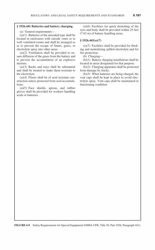
§ 1926.441 Batteries and battery charging.
(a) General requirements—(a)(1) Batteries of the unsealed type shall be
located in enclosures with outside vents or inwell ventilated rooms and shall be arranged soas to prevent the escape of fumes, gases, orelectrolyte spray into other areas.
(a)(2) Ventilation shall be provided to en-sure diffusion of the gases from the battery andto prevent the accumulation of an explosivemixture.
(a)(3) Racks and trays shall be substantialand shall be treated to make them resistant tothe electrolyte.
(a)(4) Floors shall be of acid resistant con-struction unless protected from acid accumula-tions.
(a)(5) Face shields, aprons, and rubbergloves shall be provided for workers handlingacids or batteries.
(a)(6) Facilities for quick drenching of theeyes and body shall be provided within 25 feet(7.62 m) of battery handling areas.
§ 1926.441(a)(7)
(a)(7) Facilities shall be provided for flush-ing and neutralizing spilled electrolyte and forfire protection.
(b) Charging—(b)(1) Battery charging installations shall be
located in areas designated for that purpose.(b)(2) Charging apparatus shall be protected
from damage by trucks.(b)(3) When batteries are being charged, the
vent caps shall be kept in place to avoid elec-trolyte spray. Vent caps shall be maintained infunctioning condition.
REGULATORY AND LEGAL SAFETY REQUIREMENTS AND STANDARDS 6.187
FIGURE 6.9 Safety Requirements for Special Equipment (OSHA-CFR, Title 29, Part 1926, Paragraph 441).
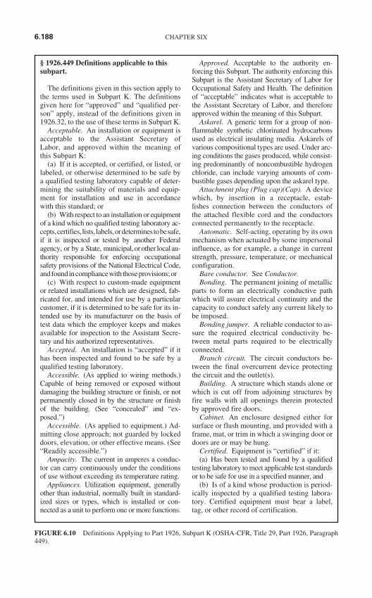
§ 1926.449 Definitions applicable to this subpart.
The definitions given in this section apply tothe terms used in Subpart K. The definitionsgiven here for “approved” and “qualified per-son” apply, instead of the definitions given in1926.32, to the use of these terms in Subpart K.
Acceptable. An installation or equipment isacceptable to the Assistant Secretary ofLabor, and approved within the meaning ofthis Subpart K:
(a) If it is accepted, or certified, or listed, orlabeled, or otherwise determined to be safe bya qualified testing laboratory capable of deter-mining the suitability of materials and equip-ment for installation and use in accordancewith this standard; or
(b) With respect to an installation or equipmentof a kind which no qualified testing laboratory ac-cepts,certifies, lists, labels,ordeterminestobesafe,if it is inspected or tested by another Federalagency, or by a State, municipal,orother localau-thority responsible for enforcing occupationalsafety provisions of the National Electrical Code,andfoundincompliancewith thoseprovisions;or
(c) With respect to custom-made equipmentor related installations which are designed, fab-ricated for, and intended for use by a particularcustomer, if it is determined to be safe for its in-tended use by its manufacturer on the basis oftest data which the employer keeps and makesavailable for inspection to the Assistant Secre-tary and his authorized representatives.
Accepted. An installation is “accepted” if ithas been inspected and found to be safe by aqualified testing laboratory.
Accessible. (As applied to wiring methods.)Capable of being removed or exposed withoutdamaging the building structure or finish, or notpermanently closed in by the structure or finishof the building. (See “concealed” and “ex-posed.”)
Accessible. (As applied to equipment.) Ad-mitting close approach; not guarded by lockeddoors, elevation, or other effective means. (See“Readily accessible.”)
Ampacity. The current in amperes a conduc-tor can carry continuously under the conditionsof use without exceeding its temperature rating.
Appliances. Utilization equipment, generallyother than industrial, normally built in standard-ized sizes or types, which is installed or con-nected as a unit to perform one or more functions.
Approved. Acceptable to the authority en-forcing this Subpart. The authority enforcing thisSubpart is the Assistant Secretary of Labor forOccupational Safety and Health. The definitionof “acceptable” indicates what is acceptable tothe Assistant Secretary of Labor, and thereforeapproved within the meaning of this Subpart.
Askarel. A generic term for a group of non-flammable synthetic chlorinated hydrocarbonsused as electrical insulating media. Askarels ofvarious compositional types are used. Under arc-ing conditions the gases produced, while consist-ing predominantly of noncombustible hydrogenchloride, can include varying amounts of com-bustible gases depending upon the askarel type.
Attachment plug (Plug cap)(Cap). A devicewhich, by insertion in a receptacle, estab-lishes connection between the conductors ofthe attached flexible cord and the conductorsconnected permanently to the receptacle.
Automatic. Self-acting, operating by its ownmechanism when actuated by some impersonalinfluence, as for example, a change in currentstrength, pressure, temperature, or mechanicalconfiguration.
Bare conductor. See Conductor.Bonding. The permanent joining of metallic
parts to form an electrically conductive pathwhich will assure electrical continuity and thecapacity to conduct safely any current likely tobe imposed.
Bonding jumper. A reliable conductor to as-sure the required electrical conductivity be-tween metal parts required to be electricallyconnected.
Branch circuit. The circuit conductors be-tween the final overcurrent device protectingthe circuit and the outlet(s).
Building. A structure which stands alone orwhich is cut off from adjoining structures byfire walls with all openings therein protectedby approved fire doors.
Cabinet. An enclosure designed either forsurface or flush mounting, and provided with aframe, mat, or trim in which a swinging door ordoors are or may be hung.
Certified. Equipment is “certified” if it:(a) Has been tested and found by a qualified
testing laboratory to meet applicable test standardsor to be safe for use in a specified manner, and
(b) Is of a kind whose production is period-ically inspected by a qualified testing labora-tory. Certified equipment must bear a label,tag, or other record of certification.
6.188 CHAPTER SIX
FIGURE 6.10 Definitions Applying to Part 1926, Subpart K (OSHA-CFR, Title 29, Part 1926, Paragraph449).
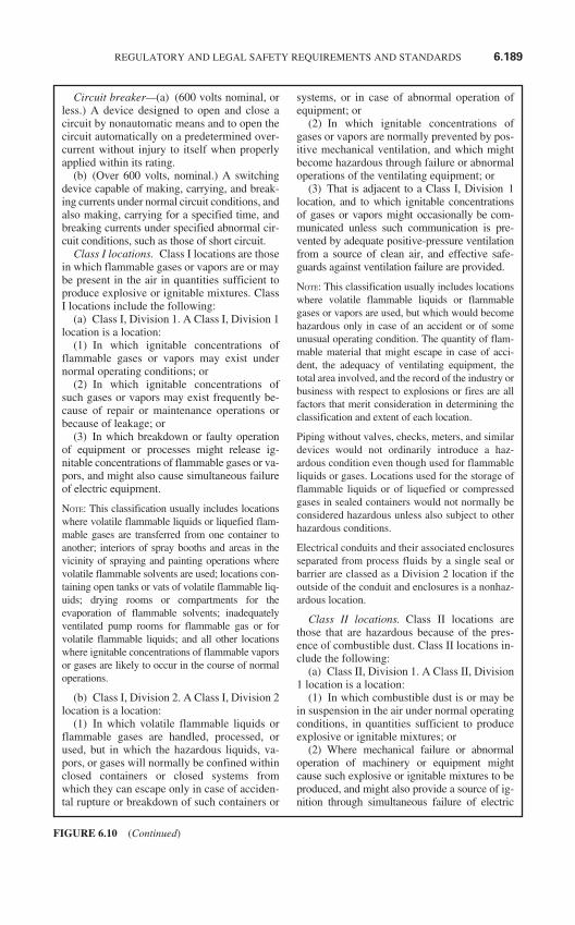
Circuit breaker—(a) (600 volts nominal, orless.) A device designed to open and close acircuit by nonautomatic means and to open thecircuit automatically on a predetermined over-current without injury to itself when properlyapplied within its rating.
(b) (Over 600 volts, nominal.) A switchingdevice capable of making, carrying, and break-ing currents under normal circuit conditions, andalso making, carrying for a specified time, andbreaking currents under specified abnormal cir-cuit conditions, such as those of short circuit.
Class I locations. Class I locations are thosein which flammable gases or vapors are or maybe present in the air in quantities sufficient toproduce explosive or ignitable mixtures. ClassI locations include the following:
(a) Class I, Division 1. A Class I, Division 1location is a location:
(1) In which ignitable concentrations offlammable gases or vapors may exist undernormal operating conditions; or
(2) In which ignitable concentrations ofsuch gases or vapors may exist frequently be-cause of repair or maintenance operations orbecause of leakage; or
(3) In which breakdown or faulty operationof equipment or processes might release ig-nitable concentrations of flammable gases or va-pors, and might also cause simultaneous failureof electric equipment.
NOTE: This classification usually includes locationswhere volatile flammable liquids or liquefied flam-mable gases are transferred from one container toanother; interiors of spray booths and areas in thevicinity of spraying and painting operations wherevolatile flammable solvents are used; locations con-taining open tanks or vats of volatile flammable liq-uids; drying rooms or compartments for theevaporation of flammable solvents; inadequatelyventilated pump rooms for flammable gas or forvolatile flammable liquids; and all other locationswhere ignitable concentrations of flammable vaporsor gases are likely to occur in the course of normaloperations.
(b) Class I, Division 2. A Class I, Division 2location is a location:
(1) In which volatile flammable liquids orflammable gases are handled, processed, orused, but in which the hazardous liquids, va-pors, or gases will normally be confined withinclosed containers or closed systems fromwhich they can escape only in case of acciden-tal rupture or breakdown of such containers or
systems, or in case of abnormal operation ofequipment; or
(2) In which ignitable concentrations ofgases or vapors are normally prevented by pos-itive mechanical ventilation, and which mightbecome hazardous through failure or abnormaloperations of the ventilating equipment; or
(3) That is adjacent to a Class I, Division 1location, and to which ignitable concentrationsof gases or vapors might occasionally be com-municated unless such communication is pre-vented by adequate positive-pressure ventilationfrom a source of clean air, and effective safe-guards against ventilation failure are provided.
NOTE: This classification usually includes locationswhere volatile flammable liquids or flammablegases or vapors are used, but which would becomehazardous only in case of an accident or of someunusual operating condition. The quantity of flam-mable material that might escape in case of acci-dent, the adequacy of ventilating equipment, thetotal area involved, and the record of the industry orbusiness with respect to explosions or fires are allfactors that merit consideration in determining theclassification and extent of each location.
Piping without valves, checks, meters, and similardevices would not ordinarily introduce a haz-ardous condition even though used for flammableliquids or gases. Locations used for the storage offlammable liquids or of liquefied or compressedgases in sealed containers would not normally beconsidered hazardous unless also subject to otherhazardous conditions.
Electrical conduits and their associated enclosuresseparated from process fluids by a single seal orbarrier are classed as a Division 2 location if theoutside of the conduit and enclosures is a nonhaz-ardous location.
Class II locations. Class II locations arethose that are hazardous because of the pres-ence of combustible dust. Class II locations in-clude the following:
(a) Class II, Division 1. A Class II, Division1 location is a location:
(1) In which combustible dust is or may bein suspension in the air under normal operatingconditions, in quantities sufficient to produceexplosive or ignitable mixtures; or
(2) Where mechanical failure or abnormaloperation of machinery or equipment mightcause such explosive or ignitable mixtures to beproduced, and might also provide a source of ig-nition through simultaneous failure of electric
REGULATORY AND LEGAL SAFETY REQUIREMENTS AND STANDARDS 6.189
FIGURE 6.10 (Continued)
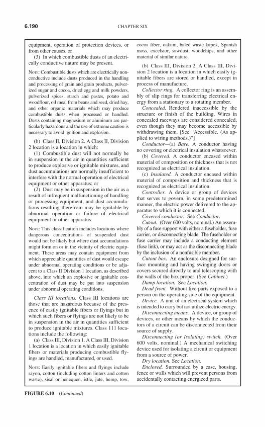
equipment, operation of protection devices, orfrom other causes, or
(3) In which combustible dusts of an electri-cally conductive nature may be present.
NOTE: Combustible dusts which are electrically non-conductive include dusts produced in the handlingand processing of grain and grain products, pulver-ized sugar and cocoa, dried egg and milk powders,pulverized spices, starch and pastes, potato andwoodflour, oil meal from beans and seed, dried hay,and other organic materials which may producecombustible dusts when processed or handled.Dusts containing magnesium or aluminum are par-ticularly hazardous and the use of extreme caution isnecessary to avoid ignition and explosion.
(b) Class II, Division 2. A Class II, Division2 location is a location in which:
(1) Combustible dust will not normally bein suspension in the air in quantities sufficientto produce explosive or ignitable mixtures, anddust accumulations are normally insufficient tointerfere with the normal operation of electricalequipment or other apparatus; or
(2) Dust may be in suspension in the air as aresult of infrequent malfunctioning of handlingor processing equipment, and dust accumula-tions resulting therefrom may be ignitable byabnormal operation or failure of electricalequipment or other apparatus.
NOTE: This classification includes locations wheredangerous concentrations of suspended dustwould not be likely but where dust accumulationsmight form on or in the vicinity of electric equip-ment. These areas may contain equipment fromwhich appreciable quantities of dust would escapeunder abnormal operating conditions or be adja-cent to a Class II Division 1 location, as describedabove, into which an explosive or ignitable con-centration of dust may be put into suspensionunder abnormal operating conditions.
Class III locations. Class III locations arethose that are hazardous because of the pres-ence of easily ignitable fibers or flyings but inwhich such fibers or flyings are not likely to bein suspension in the air in quantities sufficientto produce ignitable mixtures. Class 111 loca-tions include the following:
(a) Class III, Division 1. A Class III, Division1 location is a location in which easily ignitablefibers or materials producing combustible fly-ings are handled, manufactured, or used.
NOTE: Easily ignitable fibers and flyings includerayon, cotton (including cotton linters and cottonwaste), sisal or henequen, istle, jute, hemp, tow,
cocoa fiber, oakum, baled waste kapok, Spanishmoss, excelsior, sawdust, woodchips, and othermaterial of similar nature.
(b) Class III, Division 2. A Class III, Divi-sion 2 location is a location in which easily ig-nitable fibers are stored or handled, except inprocess of manufacture.
Collector ring. A collector ring is an assem-bly of slip rings for transferring electrical en-ergy from a stationary to a rotating member.
Concealed. Rendered inaccessible by thestructure or finish of the building. Wires inconcealed raceways are considered concealed,even though they may become accessible bywithdrawing them. [See “Accessible. (As ap-plied to wiring methods.)”]
Conductor—(a) Bare. A conductor havingno covering or electrical insulation whatsoever.
(b) Covered. A conductor encased withinmaterial of composition or thickness that is notrecognized as electrical insulation.
(c) Insulated. A conductor encased withinmaterial of composition and thickness that isrecognized as electrical insulation.
Controller. A device or group of devicesthat serves to govern, in some predeterminedmanner, the electric power delivered to the ap-paratus to which it is connected.
Covered conductor. See Conductor.Cutout. (Over 600 volts, nominal.) An assem-
bly of a fuse support with either a fuseholder, fusecarrier, or disconnecting blade. The fuseholder orfuse carrier may include a conducting element(fuse link), or may act as the disconnecting bladeby the inclusion of a nonfusible member.
Cutout box. An enclosure designed for sur-face mounting and having swinging doors orcovers secured directly to and telescoping withthe walls of the box proper. (See Cabinet.)
Damp location. See Location.Dead front. Without live parts exposed to a
person on the operating side of the equipment.Device. A unit of an electrical system which
is intended to carry but not utilize electric energy.Disconnecting means. A device, or group of
devices, or other means by which the conduc-tors of a circuit can be disconnected from theirsource of supply.
Disconnecting (or Isolating) switch. (Over600 volts, nominal.) A mechanical switchingdevice used for isolating a circuit or equipmentfrom a source of power.
Dry location. See Location.Enclosed. Surrounded by a case, housing,
fence or walls which will prevent persons fromaccidentally contacting energized parts.
6.190 CHAPTER SIX
FIGURE 6.10 (Continued)
Enclosure. The case or housing of appara-tus, or the fence or walls surrounding an instal-lation to prevent personnel from accidentallycontacting energized parts, or to protect theequipment from physical damage.
Equipment. A general term including mate-rial, fittings, devices, appliances, fixtures, ap-paratus, and the like, used as a part of, or inconnection with, an electrical installation.
Equipment grounding conductor. See Ground-ing conductor, equipment.
Explosion-proof apparatus. Apparatus en-closed in a case that is capable of withstandingan explosion of a specified gas or vapor whichmay occur within it and of preventing the igni-tion of a specified gas or vapor surrounding theenclosure by sparks, flashes, or explosion ofthe gas or vapor within, and which operates atsuch an external temperature that it will not ig-nite a surrounding flammable atmosphere.
Exposed. (As applied to live parts.) Capableof being inadvertently touched or approachednearer than a safe distance by a person. It is ap-plied to parts not suitably guarded, isolated, orinsulated. (See Accessible and Concealed.)
Exposed. (As applied to wiring methods.)On or attached to the surface or behind panelsdesigned to allow access. [See Accessible. (Asapplied to wiring methods.)”]
Exposed. (For the purposes of 1926.408(d),Communications systems.) Where the circuit isin such a position that in case of failure of sup-ports or insulation, contact with another circuitmay result.
Externally operable. Capable of being oper-ated without exposing the operator to contactwith live parts.
Feeder. All circuit conductors between theservice equipment, or the generator switch-board of an isolated plant, and the final branch-circuit overcurrent device.
Festoon lighting. A string of outdoor lightssuspended between two points more than 15feet (4.57 m) apart.
Fitting. An accessory such as a locknut,bushing, or other part of a wiring system that isintended primarily to perform a mechanicalrather than an electrical function.
Fuse. (Over 600 volts, nominal.) An over-current protective device with a circuit openingfusible part that is heated and severed by thepassage of overcurrent through it. A fuse com-prises all the parts that form a unit capable ofperforming the prescribed functions. It may ormay not be the complete device necessary toconnect it into an electrical circuit.
Ground. A conducting connection, whetherintentional or accidental, between an electricalcircuit or equipment and the earth, or to someconducting body that serves in place of theearth.
Grounded. Connected to earth or to someconducting body that serves in place of theearth.
Grounded, effectively (Over 600 volts, nom-inal.) Permanently connected to earth througha ground connection of sufficiently low imped-ance and having sufficient ampacity thatground fault current which may occur cannotbuild up to voltages dangerous to personnel.
Grounded conductor. A system or circuitconductor that is intentionally grounded.
Grounding conductor. A conductor used toconnect equipment or the grounded circuit of awiring system to a grounding electrode or elec-trodes.
Grounding conductor, equipment. The con-ductor used to connect the noncurrent-carryingmetal parts of equipment, raceways, and otherenclosures to the system grounded conductorand/or the grounding electrode conductor at theservice equipment or at the source of a sepa-rately derived system.
Grounding electrode conductor. The con-ductor used to connect the grounding electrodeto the equipment grounding conductor and/orto the grounded conductor of the circuit at theservice equipment or at the source of a sepa-rately derived system.
Ground-fault circuit interrupter. A devicefor the protection of personnel that functions todeenergize a circuit or portion thereof withinan established period of time when a current toground exceeds some predetermined value thatis less than that required to operate the overcur-rent protective device of the supply circuit.
Guarded. Covered, shielded, fenced, enclosed,or otherwise protected by means of suitable cov-ers, casings, barriers, rails, screens, mats, or plat-forms to remove the likelihood of approach to apoint of danger or contact by persons or objects.
Hoistway. Any shaftway, hatchway, wellhole, or other vertical opening or space in whichan elevator or dumbwaiter is designed to operate.
Identified (conductors or terminals). Identi-fied, as used in reference to a conductor or itsterminal, means that such conductor or termi-nal can be recognized as grounded.
Identified (for the use). Recognized as suit-able for the specific purpose, function, use, envi-ronment, application, etc. where described as arequirement in this standard. Suitability of
REGULATORY AND LEGAL SAFETY REQUIREMENTS AND STANDARDS 6.191
FIGURE 6.10 (Continued)
equipment for a specific purpose, environment,or application is determined by a qualified test-ing laboratory where such identification in-cludes labeling or listing.
Insulated conductor. See Conductor.Interrupter switch. (Over 600 volts, nomi-
nal.) A switch capable of making, carrying, andinterrupting specified currents.
Intrinsically safe equipment and associatedwiring. Equipment and associated wiring inwhich any spark or thermal effect, produced ei-ther normally or in specified fault conditions, isincapable, under certain prescribed test condi-tions, of causing ignition of a mixture of flam-mable or combustible material in air in its mosteasily ignitable concentration.
Isolated. Not readily accessible to personsunless special means for access are used.
Isolated power system. A system compris-ing an isolating transformer or its equivalent, aline isolation monitor, and its ungrounded cir-cuit conductors.
Labeled. Equipment or materials to whichhas been attached a label, symbol or other iden-tifying mark of a qualified testing laboratorywhich indicates compliance with appropriatestandards or performance in a specified manner.
Lighting outlet. An outlet intended for the di-rect connection of a lampholder, a lighting fix-ture, or a pendant cord terminating in alampholder.
Listed. Equipment or materials included in alist published by a qualified testing laboratorywhose listing states either that the equipment ormaterial meets appropriate standards or hasbeen tested and found suitable for use in a spec-ified manner.
Location—(a) Damp location. Partially pro-tected locations under canopies, marquees,roofed open porches, and like locations, and in-terior locations subject to moderate degrees ofmoisture, such as some basements.
(b) Dry location. A location not normallysubject to dampness or wetness. A locationclassified as dry may be temporarily subject todampness or wetness, as in the case of a build-ing under construction.
(c) Wet location. Installations undergroundor in concrete slabs or masonry in direct con-tact with the earth, and locations subject to sat-uration with water or other liquids, such aslocations exposed to weather and unprotected.
Mobile X-ray. X-ray equipment mounted ona permanent base with wheels and/or casters formoving while completely assembled.
Motor control center. An assembly of oneor more enclosed sections having a commonpower bus and principally containing motorcontrol units.
Outlet. A point on the wiring system at whichcurrent is taken to supply utilization equipment.
Overcurrent. Any current in excess of therated current of equipment or the ampacity of aconductor. It may result from overload (see defi-nition), short circuit, or ground fault. A current inexcess of rating may be accommodated by cer-tain equipment and conductors for a given set ofconditions. Hence the rules for overcurrent pro-tection are specific for particular situations.
Overload. Operation of equipment in ex-cess of normal, full load rating, or of a conduc-tor in excess of rated ampacity which, when itpersists for a sufficient length of time, wouldcause damage or dangerous overheating. Afault, such as a short circuit or ground fault, isnot an overload. (See “Overcurrent.”)
Panelboard. A single panel or group of panelunits designed for assembly in the form of a sin-gle panel; including buses, automatic overcurrentdevices, and with or without switches for thecontrol of light, heat, or power circuits; designedto be placed in a cabinet or cutout box placed inor against a wall or partition and accessible onlyfrom the front. (See “Switchboard.”)
Portable X-ray. X-ray equipment designedto be hand-carried.
Power fuse. (Over 600 volts, nominal.) See“Fuse.”
Power outlet. An enclosed assembly whichmay include receptacles, circuit breakers, fuse-holders, fused switches, buses and watt-hourmeter mounting means; intended to serve as ameans for distributing power required to oper-ate mobile or temporarily installed equipment.
Premises wiring system. That interior andexterior wiring, including power, lighting,control, and signal circuit wiring togetherwith all of its associated hardware, fittings,and wiring devices, both permanently andtemporarily installed, which extends from theload end of the service drop, or load end ofthe service lateral conductors to the outlet(s).Such wiring does not include wiring internalto appliances, fixtures, motors, controllers,motor control centers, and similar equipment.
Qualified person. One familiar with the con-struction and operation of the equipment andthe hazards involved.
Qualified testing laboratory. A properlyequipped and staffed testing laboratory which
6.192 CHAPTER SIX
FIGURE 6.10 (Continued)

has capabilities for and which provides the fol-lowing services:
(a) Experimental testing for safety of speci-fied items of equipment and materials referredto in this standard to determine compliancewith appropriate test standards or performancein a specified manner;
(b) Inspecting the run of such items ofequipment and materials at factories for prod-uct evaluation to assure compliance with thetest standards;
(c) Service-value determinations through fieldinspections to monitor the proper use of labels onproducts and with authority for recall of the labelin the event a hazardous product is installed;
(d) Employing a controlled procedure foridentifying the listed and/or labeled equipmentor materials tested; and
(e) Rendering creditable reports or findingsthat are objective and without bias of the testsand test methods employed.
Raceway. A channel designed expressly forholding wires, cables, or busbars, with addi-tional functions as permitted in this subpart.Raceways may be of metal or insulating mater-ial, and the term includes rigid metal conduit,rigid nonmetallic conduit, intermediate metalconduit, liquidtight flexible metal conduit, flexi-ble metallic tubing, flexible metal conduit, elec-trical metallic tubing, underfloor raceways,cellular concrete floor raceways, cellular metalfloor raceways, surface raceways, wireways,and busways.
Readily accessible. Capable of being reachedquickly for operation, renewal, or inspections,without requiring those to whom ready access isrequisite to climb over or remove obstacles or toresort to portable ladders, chairs, etc. (See“Accessible.”)
Receptacle. A receptacle is a contact deviceinstalled at the outlet for the connection of a sin-gle attachment plug. A single receptacle is a sin-gle contact device with no other contact deviceon the same yoke. A multiple receptacle is a sin-gle device containing two or more receptacles.
Receptacle outlet. An outlet where one ormore receptacles are installed.
Remote-control circuit. Any electric circuitthat controls any other circuit through a relayor an equivalent device.
Sealable equipment. Equipment enclosed ina case or cabinet that is provided with a means ofsealing or locking so that live parts cannot bemade accessible without opening the enclosure.The equipment may or may not be operablewithout opening the enclosure.
Separately derived system. A premises wiringsystem whose power is derived from generator,transformer, or converter windings and has nodirect electrical connection, including a solidlyconnected grounded circuit conductor, to supplyconductors originating in another system.
Service. The conductors and equipment fordelivering energy from the electricity supply sys-tem to the wiring system of the premises served.
Service conductors. The supply conductorsthat extend from the street main or from trans-formers to the service equipment of thepremises supplied.
Service drop. The overhead service conduc-tors from the last pole or other aerial support toand including the splices, if any, connecting tothe service-entrance conductors at the buildingor other structure.
Service-entrance conductors, overhead sys-tem. The service conductors between the termi-nals of the service equipment and a point usuallyoutside the building, clear of building walls,where joined by tap or splice to the service drop.
Service-entrance conductors, undergroundsystem. The service conductors between the ter-minals of the service equipment and the point ofconnection to the service lateral. Where serviceequipment is located outside the building walls,there may be no service-entrance conductors, orthey may be entirely outside the building.
Service equipment. The necessary equip-ment, usually consisting of a circuit breaker orswitch and fuses, and their accessories, locatednear the point of entrance of supply conductorsto a building or other structure, or an otherwisedefined area, and intended to constitute themain control and means of cutoff of the supply.
Service raceway. The raceway that enclosesthe service-entrance conductors.
Signaling circuit. Any electric circuit thatenergizes signaling equipment.
Switchboard. A large single panel, frame, orassembly of panels which have switches, buses,instruments, overcurrent and other protectivedevices mounted on the face or back or both.Switchboards are generally accessible from therear as well as from the front and are not in-tended to be installed in cabinets. (See Panel-board.)
Switches—(a) General-use switch. A switchintended for use in general distribution andbranch circuits. It is rated in amperes, and it iscapable of interrupting its rated current at itsrated voltage.
(b) General-use snap switch. A form ofgeneral-use switch so constructed that it can be
REGULATORY AND LEGAL SAFETY REQUIREMENTS AND STANDARDS 6.193
FIGURE 6.10 (Continued)
installed in flush device boxes or on outlet boxcovers, or otherwise used in conjunction withwiring systems recognized by this subpart.
(c) Isolating switch. A switch intended forisolating an electric circuit from the source ofpower. It has no interrupting rating, and it is in-tended to be operated only after the circuit hasbeen opened by some other means.
(d) Motor-circuit switch. A switch, rated inhorsepower, capable of interrupting the maxi-mum operating overload current of a motor ofthe same horsepower rating as the switch at therated voltage.
Switching devices. (Over 600 volts, nomi-nal.) Devices designed to close and/or openone or more electric circuits. Included in thiscategory are circuit breakers, cutouts, discon-necting (or isolating) switches, disconnectingmeans, and interrupter switches.
Transportable X-ray. X-ray equipment in-stalled in a vehicle or that may readily be disas-sembled for transport in a vehicle.
Utilization equipment. Utilization equipmentmeans equipment which utilizes electric energyfor mechanical, chemical, heating, lighting, orsimilar useful purpose.
Utilization system. A utilization system is a sys-tem which provides electric power and light for em-ployee workplaces, and includes the premiseswiring system and utilization equipment.
Ventilated. Provided with a means to permitcirculation of air sufficient to remove an excessof heat, fumes, or vapors.
Volatile flammable liquid. A flammable liq-uid having a flash point below 38 degrees C(100 degrees F) or whose temperature is aboveits flash point, or a Class II combustible liquidhaving a vapor pressure not exceeding 40 psia(276 kPa) at 38 deg. C (100 deg. F) whose tem-perature is above its flash point.
Voltage. (Of a circuit.) The greatest root-mean-square (effective) difference of potential betweenany two conductors of the circuit concerned.
Voltage, nominal. A nominal value as-signed to a circuit or system for the purpose ofconveniently designating its voltage class (as120/240, 480Y/277, 600, etc.). The actual volt-age at which a circuit operates can vary fromthe nominal within a range that permits satis-factory operation of equipment.
Voltage to ground. For grounded circuits,the voltage between the given conductor andthat point or conductor of the circuit that isgrounded; for ungrounded circuits, the greatestvoltage between the given conductor and anyother conductor of the circuit.
Watertight. So constructed that moisturewill not enter the enclosure.
Weatherproof. So constructed or protectedthat exposure to the weather will not interferewith successful operation. Rainproof, raintight,or watertight equipment can fulfill the require-ments for weatherproof where varying weatherconditions other than wetness, such as snow, ice,dust, or temperature extremes, are not a factor.
Wet location. See Location.
6.194 CHAPTER SIX
FIGURE 6.10 (Continued)
CHAPTER 7ACCIDENT PREVENTION,
ACCIDENT INVESTIGATION,RESCUE, AND FIRST AID
ACCIDENT PREVENTION
No matter how carefully a system is engineered, no matter how carefully employees performtheir tasks, and no matter how well trained employees are in the recognition and avoidance ofhazards, accidents still happen. This section provides a general approach that may beemployed to reduce the number and severity of accidents. Four basic steps—employeeresponsibility, safe installations, safe work practices, and employee training—combine to cre-ate the type of safe work environment that should be the goal of every facility.
Individual Responsibility
The person most responsible for your own personal safety is you. No set of regulations,rules, or procedures can ever replace common sense in the workplace. This statementshould not be construed to mean an employer has no responsibility to provide the safestpractical work environment, nor does it mean that the injured person is “at fault” in a legalsense. Determining fault for accidents is, in part, a legal problem and is beyond the scopeof this handbook.
Time after time, accident investigations reveal that the injured person was the last linkin the chain. If the injured person had only been wearing appropriate safety equipment orfollowing proper procedures, or if he or she had only checked one last time, the accidentnever would have occurred.
Table 7.1 lists five behavioral approaches that will help to improve the safety of allemployees. To make certain employees have both the responsibility and the authority tocarry out the five steps listed in Table 7.1, employers should adopt a policy similar to theone listed in Table 7.2. Simply putting such a statement in a safety handbook is insuffi-cient. An employer must believe in this principle and must “put teeth into it.” Such a credoprovides the absolute maximum in individual employee responsibility and authority andwill maximize the safety performance of the organization.
Installation Safety
Design. Proper design of electrical systems is composed of three parts—selection, instal-lation, and calibration.
7.1
Copyright © 2006 by The McGraw-Hill Companies, Inc. Click here for terms of use.
7.2 CHAPTER SEVEN
Selection. Electric equipment should be selected and applied conservatively. That is, max-imum ratings must be well in excess of the quantities to which they will be exposed in thepower system. To help with this, manufacturing organizations such as the National ElectricalManufacturer’s Association (NEMA) have established ratings for equipment that ensuremember companies only manufacture the highest-quality equipment. Equipment is testedper manufacturer’s procedures by independent laboratories such as the Underwriter’sLaboratory (UL). Equipment that is rated and labeled by such organizations should be usedin electrical systems to help ensure safety. OSHA, NEC,* and NESC requirements shouldbe considered as minimum criteria for safe selection. With increasing cost consciousness,many companies are opting for the installation of recycled rather than brand-new equipment.While the selection and use of such equipment can be a financial advantage, at least two cri-teria should be considered in the purchase:
1. Even though used, the equipment should have been originally manufactured by a rep-utable, professional firm.
2. The recycled equipment should be thoroughly reconditioned by a professional recy-cling company such as those represented by the Professional Electrical ApparatusRecyclers League.
3. Engineering studies such as short-circuit analysis and coordination studies must beperformed to ascertain that the recycled equipment has adequate ratings for the sys-tem in which it is being placed. Since the system short circuit values may change withtime, this requirement is true even if the recycled equipment is a direct replacementfor the previous equipment.
Installation. Equipment should be installed in a safe and sensible manner. Adequatework spaces for safety clearance should be allowed, safety barriers should be providedwhen necessary, and electrical installations should never be mixed with areas that areused for general public access.
Calibration. Equipment always should be properly calibrated. For example, protectivedevices should be calibrated so that they will operate for the minimum abnormal system
* National Electrical Code and NEC are registered trademarks of the National Fire Protection Association.
TABLE 7.1 Employee Safety Behavior
• Determine the nature and extent of hazards before starting a job.• Each employee should be satisfied that conditions are safe before beginning work on any job or
any part of a job.• All employees should be thoroughly familiar with and should consistently use the work procedures
and the safety equipment required for the performance of the job at hand.• While working, each employee should consider the effects of each step and do nothing that might
endanger themselves or others.• Each employee should be thoroughly familiar with emergency procedures.
TABLE 7.2 Recommended Safety Credo
If it cannot be done safely, it need not be done!
condition. Equipment that is improperly calibrated can result in accidents as though the equip-ment had been improperly selected to begin with. Calibration is also a two-step process:
1. Proper engineering should be performed by professional engineers to ensure that theselected calibration settings are suitable for the application. The starting point for sucha system is in the performance of an appropriate suite of power system studies,described later in the section.
2. Proper testing and physical setting of the devices should be carried out to ensure thatthe equipment is capable of performing when called upon. Such settings should be exe-cuted by professional technicians who are certified to perform this work. Organizationssuch as the International Electrical Testing Association (NETA) have been formed toensure quality control on the education and performance of electrical technicians.
Electrical Protective Devices. Protective devices such as circuit breakers, fuses, and switchesmust be capable of interrupting the currents to which they will be subjected. The NationalElectrical Code has numerous passages that require proper sizing of protective devices.
Maintenance. Improperly maintained equipment is hazardous. For example, circuit break-ers can explode violently if not properly maintained. Equipment should be periodicallyinspected and tested. If deficiencies are observed, the equipment must be repaired, adjusted,or replaced as required. Properly trained and certified technicians and mechanics should beused for such work. As mentioned earlier, national organizations such as NETA can be usedto provide qualified personnel.
Operating Schemes. Many personal injury accidents could be prevented if systems wereall designed for safe operating procedures. The following are some of the key design con-cepts that should be used for any new or refurbished electrical system:
1. Arc-resistant switchgear should be employed. In addition to reducing the possibility ofelectrical arcs and resulting blasts, arc-resistant switchgear is designed to contain the blastand blast products. Such switchgear also has pressure relief systems that will redirect therelease of arc and blast products and energy in directions that are safe for workers.
2. Remote operating controls should be used for all circuit breakers, switches, and other suchcontrol devices. This relatively simple and inexpensive design technique allows workers tooperate equipment while stationed remotely from the possible results of failure. Whethersupervisory control systems or simple remotely placed, hard-wired control switches areused, the distance will allow the workers to operate the equipment in relative safety.
3. Control panels should be designed with protective barriers to prevent shock hazard andcontain arcs and arc products. For example, many industrial control panels are fed via480 V circuit breakers. This breaker, in turn, feeds a step-down transformer. The controlvoltage output of the transformer feeds the various control circuit throughout the panel.If the 480 V portions of the circuit are designed with appropriate protective covers,workers in the panel need to protect themselves only from the electrical hazards pre-sented by the 120 V circuits.
Power System Studies
Power system studies are engineering procedures that must be performed. There are threedistinct times in the life of a power system when such studies should be performed:
1. During the initial design of the system to ensure that all selected equipment will performproperly during the day-to-day operation of the facility.
ACCIDENT PREVENTION, ACCIDENT INVESTIGATION, RESCUE, AND FIRST AID 7.3
2. Anytime a significant change occurs such as replacement of an existing piece of equip-ment or addition of new equipment or circuits.
3. At intervals during the life of the system to identify any possible changes that may haveoccurred externally. For example, electric utility supplies are changing constantly. Suchchanges can have a profound effect on the short-circuit currents and normal operatingvoltage levels.
The studies described in this section should be considered safety-related procedures. If theyare not performed equipment may be improperly applied and can fail, putting personnel at risk.
ANSI/IEEE standard Std-399 (IEEE Recommended Practice for Industrial andCommercial Power Systems Analysis) identifies 11 recommended power systems studies. Ofthese 11, the short-circuit analysis and protective device coordination study are among themost critical with respect to electrical safety.As described later in this section, such studies arerequired by some industry standards.
The following paragraphs briefly describe these studies and provide basic informationabout their importance and implementation. The reader is referred to the most recent edi-tion of ANSI/IEEE standard Std-399 for details. Also note that these procedures are safety-related; they should be performed only by engineers and technicians with the education andexperience to do them correctly.
Load Flow Analysis. This type of study determines the voltage, current, reactive power,active power, and power factor in an operating power system. It is performed using com-puter software and can be set up to analyze contingencies of any type. Such studies are usedto size and select equipment and will alert system operators to possible hazardous or pooroperating conditions.
Stability Analysis. Stability in a power system is defined as either transient or steady state.Steady state stability is the ability of a power system to maintain synchronism between machineswithin the system following relatively slow load changes. Transient stability is the ability tomaintain synchronism after short-term events occur, such as switching and short circuits.
Stability studies are safety-related in that they will allow the power system operator to con-tinue safe operation even when the system is exposed to abnormal or excessive events.
Motor-StartingAnalysis. When large motors are started, the high current surges and voltagedips can cause malfunction or failure of other system components. A motor-starting analysisuses a computer program to model the behavior of the system when the motor starts. This canbe used to size the power system equipment to prevent outages, and the hazards associated withthem will be reduced or eliminated.
Harmonic Analysis. Harmonics and other types of power quality problems can cause pre-mature equipment failure, malfunctions, and other types of hazardous conditions. Such fail-ures can include heating and failure of rotating machinery and power system capacitors andtheir associated hazards.A harmonic analysis is performed to pinpoint the sources of harmonicdistortion and to determine the solutions to such problems.
Switching Transients Analysis. When certain loads are switched and/or when switchesare malfunctioning, failures can occur, which can put employees at risk. A switching tran-sients study determines the magnitude of such transients and allows the system engineersto develop solutions.
Reliability Analysis. Reliability is usually expressed as the frequency of interruptions andexpected number of interruptions in a year of system operation. When properly applied, the
7.4 CHAPTER SEVEN
results of a reliability study can be used to make sure the system operates as continuously aspossible. This means that workers will not be exposed to the hazards of working on the systemto repair it.
CableAmpacityAnalysis. Cable ampacity studies determine the ampacity (current-carryingcapacity) of power cables in the power system. Properly selecting power cables and sizingthem will help to minimize unexpected failures.
Ground Mat Analysis. The subject of system grounding is covered in detail in Chap. 4. Oneof the most important pieces of equipment in the grounding system is the ground mat. A prop-erly designed and installed ground mat will reduce step and touch voltages and provide a muchsafer environment for the worker.According to IEEE standard Std-399, at least five factors needto be considered in the ground mat analysis:
1. Fault current magnitude and duration2. Geometry of the grounding system3. Soil resistivity4. Probability of contact5. Humans factors such as
(a) Body resistance(b) Standard assumptions on physical conditions of the individual
Short-Circuit Analysis and Protective Device Coordination. A short-circuit study deter-mines the magnitude of the currents that flow for faults placed at various buses throughoutthe power system. This information is used to determine interrupting requirements for fusesand circuit breakers and to set trip points for the overcurrent devices.
A coordination study is performed to make certain the overcurrent devices in a systemwill trip selectively. Selective tripping means that only the nearest upstream device to theshort circuit trips to clear the circuit.
The two studies, taken together, are used to properly select and calibrate the protectivedevices used in the power system. The information that they provide is used for the fol-lowing purposes:
Fuses and circuit breakers are selected so that they are capable of interrupting the maxi-mum fault current that will flow through them.
Instantaneous elements are selected so that they will respond (or in some cases notrespond) to the short-circuit currents that will flow through them.
Time curves and instantaneous settings are selected so that the nearest upstream deviceto the short circuit is the one that operates to clear the fault.
Protective devices are selected so that the short circuit is cleared in a minimum amountof time with as little collateral damage as possible.
Protective devices are selected so that fault currents that flow through cables and trans-formers will not cause thermal or mechanical damage to those pieces of equipment.
Each of these points is critical to the safe and economical operation of a power system.For example, if circuit breakers or fuses are incapable of interrupting fault currents, theymay explode violently, injuring personnel in the area. If the wrong protective device oper-ates, a “small” outage may expand to include an entire plant. If a transformer overload relayis too slow, the transformer may be damaged by excessive temperature rise. The only waythat such malfunctions can be avoided is to perform a short-circuit analysis and a coordi-nation study and then to select and set protective devices according to their results.
ACCIDENT PREVENTION, ACCIDENT INVESTIGATION, RESCUE, AND FIRST AID 7.5
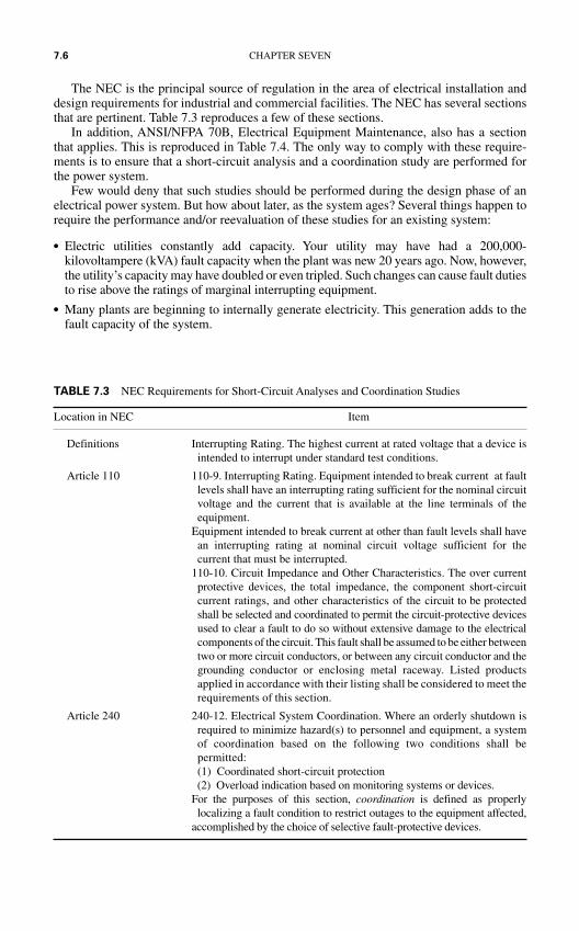
The NEC is the principal source of regulation in the area of electrical installation anddesign requirements for industrial and commercial facilities. The NEC has several sectionsthat are pertinent. Table 7.3 reproduces a few of these sections.
In addition, ANSI/NFPA 70B, Electrical Equipment Maintenance, also has a sectionthat applies. This is reproduced in Table 7.4. The only way to comply with these require-ments is to ensure that a short-circuit analysis and a coordination study are performed forthe power system.
Few would deny that such studies should be performed during the design phase of anelectrical power system. But how about later, as the system ages? Several things happen torequire the performance and/or reevaluation of these studies for an existing system:
Electric utilities constantly add capacity. Your utility may have had a 200,000-kilovoltampere (kVA) fault capacity when the plant was new 20 years ago. Now, however,the utility’s capacity may have doubled or even tripled. Such changes can cause fault dutiesto rise above the ratings of marginal interrupting equipment.
Many plants are beginning to internally generate electricity. This generation adds to thefault capacity of the system.
7.6 CHAPTER SEVEN
TABLE 7.3 NEC Requirements for Short-Circuit Analyses and Coordination Studies
Location in NEC Item
Definitions Interrupting Rating. The highest current at rated voltage that a device isintended to interrupt under standard test conditions.
Article 110 110-9. Interrupting Rating. Equipment intended to break current at faultlevels shall have an interrupting rating sufficient for the nominal circuitvoltage and the current that is available at the line terminals of theequipment.
Equipment intended to break current at other than fault levels shall havean interrupting rating at nominal circuit voltage sufficient for thecurrent that must be interrupted.
110-10. Circuit Impedance and Other Characteristics. The over currentprotective devices, the total impedance, the component short-circuitcurrent ratings, and other characteristics of the circuit to be protectedshall be selected and coordinated to permit the circuit-protective devicesused to clear a fault to do so without extensive damage to the electricalcomponents of the circuit. This fault shall be assumed to be either betweentwo or more circuit conductors, or between any circuit conductor and thegrounding conductor or enclosing metal raceway. Listed productsapplied in accordance with their listing shall be considered to meet therequirements of this section.
Article 240 240-12. Electrical System Coordination. Where an orderly shutdown isrequired to minimize hazard(s) to personnel and equipment, a systemof coordination based on the following two conditions shall bepermitted:(1) Coordinated short-circuit protection(2) Overload indication based on monitoring systems or devices.
For the purposes of this section, coordination is defined as properlylocalizing a fault condition to restrict outages to the equipment affected,
accomplished by the choice of selective fault-protective devices.
Operating procedures may have changed. A bus tie circuit breaker that was normally openmay now be normally closed. Such a change can greatly increase fault capacity.
Technical standards can change. For example, in 1985 the protection requirements forliquid-filled transformers changed. Studies showed that many transformers were beingmechanically damaged by high current through faults. The protection requirementsbecame more stringent for such installations. Although the standards do not require exist-ing systems to be changed, would it not make sense to at least review your system? Theprotection changes might be minimal.
New installations or plant modernization may add capacity and other coordinationstreams to the system. For example, coordination studies require that the main breakercoordinate with the largest feeder device. If a larger feeder device is added later, the coor-dination study must be reviewed.
In general, short-circuit analyses and coordination studies should be reviewed at leastevery 5 years. These studies should be performed by a registered professional engineer.Many consulting firms have the ability and the experience to perform them; however,since short-circuit analyses and coordination studies are specialized types of engineeringservices, not all architect and engineering firms have the experience to do them. Closelyreview the qualifications of the firm that you retain.
ANSI/IEEE standard Std-399, Power Systems Analysis, is the standard that covers mostof the engineering studies that are key to the proper design and performance of an electri-cal power system. The Brown Book is part of the IEEE color book series and should be ref-erenced when you are deciding what studies to perform and how to perform them.
Proper selection, sizing, and calibration of the protective devices in a power system directlyaffect safety, efficiency, and economics. Common sense and regulatory requirements dictatethat a short-circuit analysis and coordination study should be performed.
Arc-Flash Study. The arc-flash study is performed to determine the incident energy towhich workers will be exposed in the event that an electrical arc occurs. This study isdescribed in some detail in Chap. 3.
FIRST AID
This handbook provides general coverage of the subject with expanded information on han-dling electrical injuries. Potential first aid givers should remember four very importantpoints. Before an accident happens:
ACCIDENT PREVENTION, ACCIDENT INVESTIGATION, RESCUE, AND FIRST AID 7.7
TABLE 7.4 ANSI/NFPA 70B Requirements for Short-Circuit Analyses and Coordination Studies
ANSI/NFPA 70B Item
Paragraph 7-4.3 An up-to-date short-circuit and coordination study is essential for safety of personnel and equipment. It is necessary to analyze the momentary andinterrupting rating requirements of the protective devices. That is, will the circuitbreaker or fuse safely interrupt the fault or explode in attempting to perform thisfunction?
Para 7-4.3.1 Another phase of the study is that of developing the application of the protectivedevices to realize minimum equipment damage and the least disturbance to thesystem in the event of a fault.
7.8 CHAPTER SEVEN
TABLE 7.6 First Aid Checklist
• Is the circuit still energized?• Is the victim contacting the circuit?• Are noxious gases or materials present that may cause injury?• Is fire present or possible?
Obtain hands-on first aid training for yourself and all employees. Such training may beobtained from the American Heart Association, the American Red Cross, or local sourcessuch as fire departments or police departments.
If an accident does happen:
Act quickly!!! You may be the only person that can prevent a death. Do not administer first aid that you are
not qualified to administer. Injuries canbe aggravated by improperly adminis-tered first aid.
Get qualified medical help quickly.Paramedics and emergency medical tech-nicians are trained to provide emergencyfirst aid and should be summoned as soonas possible.
This handbook is not intended to be used asa first aid training manual. Table 7.5 sum-marizes the first aid steps that are discussedin the following sections.
General First Aid
Act Quickly. Remember—you may be the only person between the victim and death.Whatever you do, do it quickly. This does not imply that you should act impetuously. Youractions should be planned and methodical, but you should not waste any time. Do notattempt to perform procedures for which you have no training or experience. Improperlyapplied procedures can be deadly.
Survey the Situation. Remember that your purpose as a first aid giver is to help theproblem, not contribute to it. If you are injured in the process of administering first aid,you cannot help the victim. If your preliminary assessment indicates that you need towear safety clothing, put it on first, then administer aid. Table 7.6 lists key points thatshould be checked before you rush in.
Develop a Plan. After the initial survey of the situation, develop the plan of attack. Thespecifics of any given situation will vary; however, the following guidelines should be used:
If the victim is in immediate danger, he or she should be moved to a safe position. (See thenext section on moving the victim and later sections on rescue techniques.)
If the victim is nonresponsive, assess his or her condition and respond accordingly. (Seethe later section on assessing the victim’s condition.)
TABLE 7.5 General First Aid Procedure
• Act quickly.• Survey the situation.• Develop a plan.• Assess the victim’s condition.• Summon help if needed.• Move the victim only if danger is imminent.• Administer required first aid:
ShockElectrical burns
ACCIDENT PREVENTION, ACCIDENT INVESTIGATION, RESCUE, AND FIRST AID 7.9
If the victim is responsive, make him or her as comfortable as possible and summon aid.Do not abandon the victim until aid has arrived.
Constantly monitor the condition of the victim. Electric shock can cause delayed failuresand irregularities of heart rhythm.
Assess the Victim’s Condition. The procedures to be used in administering first aiddepend on the condition of the victim. If the victim is responsive, no action may berequired. Table 7.7 lists the procedures to perform if the victim is awake and responsive.
If the victim is not responsive, you must perform a “hands-on” assessment of his or her con-dition. Table 7.8 lists the ABCs of first aid. This memory device can help the first aid giver toremember the proper procedure when examining a nonresponsive victim.
One of the biggest surprises to those who havenot worked with accident victims is that thetrauma of the accident can induce severe bleedingthrough the mouth and/or vomiting. Be preparedfor these conditions before working with aninjured person. When you have prepared yourselffor this situation, begin the ABCs.
A—Check the victim’s Airway. Figure 7.1 illustrates the correct way to clear an injuredperson’s airway. Remember to avoid moving the victim and to keep the victim’s spinestraight to avoid aggravating an injury. Caution: An accident victim may suffer frominvoluntary muscular reflexes and other such spasms. The strongest muscle in the humanbody is the jaw. Because of this, rescue workers should put their fingers into the victim’smouth only when absolutely necessary.
Start by opening the victim’s mouth as shown in Fig. 7.1. Search the mouth for foreignmatter or other objects that may be blocking the air passage. Many times the victim’stongue may be blocking the air passage. To fix this problem, put your hand behind the vic-tim’s neck, gently pull the jaw forward, and, if required, carefully tilt the head back. If theair passage is clear and the victim is still not breathing, you should perform resuscitation.
B—Check the victim’s Breathing. First check to see if the victim is breathing. This canbe done by observing his or her chest to see if it is moving. Then place your ear close tothe victim’s mouth and nose and listen carefully. If the victim is breathing but choking orgurgling sounds are heard clear the victim’s airway.
C—Check the victim’s Circulation. Circulation should be checked by feeling for thevictim’s pulse at the carotid artery as shown in Fig. 7.2. To find the carotid artery, placeyour fingertips gently on the victim’s larynx. Gently slide the fingers down into thegroove between the windpipe and the muscle at the back of the neck. The carotid
TABLE 7.7 What to Do If the Victim Is Responsive
• Ask the victim what is wrong.• Assess the victim’s condition and treat the injuries as best as possible.• Treat the worst injuries first.• When the victim is out of immediate danger, or if you are unable to help
because the injuries are beyond your abilities, summon help.• Attend to the victim(s) and keep them safe until help arrives.• When help arrives, give the first aid workers your assessment of the
situation and stand by to help.
TABLE 7.8 The ABCs of First Aid
AirwayBreathingCirculationDoctor
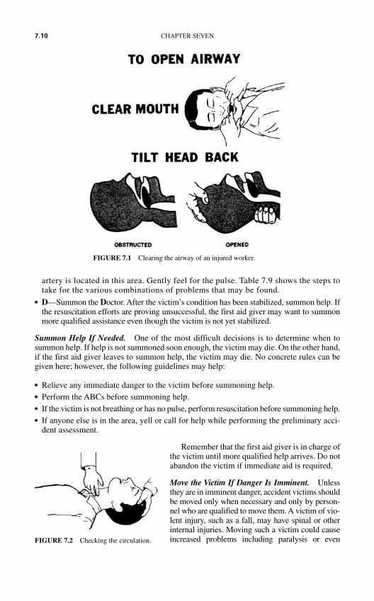
artery is located in this area. Gently feel for the pulse. Table 7.9 shows the steps totake for the various combinations of problems that may be found.
D—Summon the Doctor. After the victim’s condition has been stabilized, summon help. Ifthe resuscitation efforts are proving unsuccessful, the first aid giver may want to summonmore qualified assistance even though the victim is not yet stabilized.
Summon Help If Needed. One of the most difficult decisions is to determine when tosummon help. If help is not summoned soon enough, the victim may die. On the other hand,if the first aid giver leaves to summon help, the victim may die. No concrete rules can begiven here; however, the following guidelines may help:
Relieve any immediate danger to the victim before summoning help. Perform the ABCs before summoning help. If the victim is not breathing or has no pulse, perform resuscitation before summoning help. If anyone else is in the area, yell or call for help while performing the preliminary acci-
dent assessment.
Remember that the first aid giver is in charge ofthe victim until more qualified help arrives. Do notabandon the victim if immediate aid is required.
Move the Victim If Danger Is Imminent. Unlessthey are in imminent danger, accident victims shouldbe moved only when necessary and only by person-nel who are qualified to move them. A victim of vio-lent injury, such as a fall, may have spinal or otherinternal injuries. Moving such a victim could causeincreased problems including paralysis or even
7.10 CHAPTER SEVEN
FIGURE 7.1 Clearing the airway of an injured worker.
FIGURE 7.2 Checking the circulation.
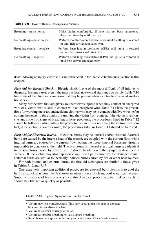
death. Moving an injury victim is discussed in detail in the “Rescue Techniques” section in thischapter.
First Aid for Electric Shock. Electric shock is one of the most difficult of all injuries todiagnose. In some cases, even if the injury is fatal, no external signs may be visible. Table 7.10lists some of the clues and symptoms that may be present when a victim has received an elec-tric shock.
Many prospective first aid givers are themselves injured when they contact an energizedwire or a victim who is still in contact with an energized wire. Table 7.11 lists the precau-tions for working on or around accident victims who may be in contact with live wires. Aftercutting the power to the circuits or removing the victim from contact, if the victim is respon-sive and shows no signs of breathing or heart problems, the procedures listed in Table 7.12should be followed. After cutting the power to the circuits or removing the victim from con-tact, if the victim is nonresponsive, the procedures listed in Table 7.13 should be followed.
First Aid for Electrical Burns. Electrical burns may be internal and/or external. Externalburns are caused by the intense heat of the electric arc coupled with the current flow, whileinternal burns are caused by the current flow heating the tissue. Internal burns are virtuallyimpossible to diagnose in the field. The symptoms of internal electrical burns are identicalto the symptoms caused by severe electric shock. In addition to the symptoms described inTable 7.10, the victim may also experience significant pain caused by the damaged tissue.External burns are similar to thermally induced burns caused by fire or other heat sources.
For both internal and external burns, the first aid techniques are similar to those givenin Tables 7.12 and 7.13.
One extremely important additional procedure for external burn victims is to cool theburns as quickly as possible. A shower or other source of clean, cool water can be used.Since the treatment of burns is a very specialized medical procedure, qualified medical helpshould be obtained as quickly as possible.
ACCIDENT PREVENTION, ACCIDENT INVESTIGATION, RESCUE, AND FIRST AID 7.11
TABLE 7.9 How to Handle Unresponsive Victims
Breathing—pulse normal Make victim comfortable. If help has not been summoned, do so and stand by until it arrives.
No breathing—pulse normal Perform mouth-to-mouth resuscitation until breathing is restoredor until help arrives and takes over.
Breathing normal—no pulse Perform heart-lung resuscitation (CPR) until pulse is restoredor until help arrives and takes over.
No breathing—no pulse Perform heart-lung resuscitation (CPR) until pulse is restored oruntil help arrives and takes over.
TABLE 7.10 Typical Symptoms of Electric Shock
• Victim may lose consciousness. This may occur at the moment of contact; however, it can also occur later.
• Victim has a weak or irregular pulse.• Victim has trouble breathing or has stopped breathing.• Small burns may appear at the entry and exit points of the electric current.
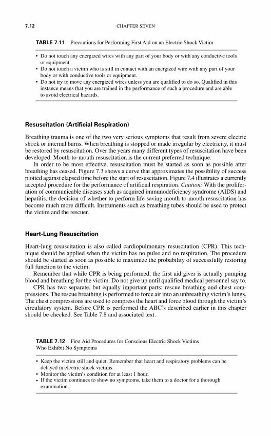
Resuscitation (Artificial Respiration)
Breathing trauma is one of the two very serious symptoms that result from severe electricshock or internal burns. When breathing is stopped or made irregular by electricity, it mustbe restored by resuscitation. Over the years many different types of resuscitation have beendeveloped. Mouth-to-mouth resuscitation is the current preferred technique.
In order to be most effective, resuscitation must be started as soon as possible afterbreathing has ceased. Figure 7.3 shows a curve that approximates the possibility of successplotted against elapsed time before the start of resuscitation. Figure 7.4 illustrates a currentlyaccepted procedure for the performance of artificial respiration. Caution: With the prolifer-ation of communicable diseases such as acquired immunodeficiency syndrome (AIDS) andhepatitis, the decision of whether to perform life-saving mouth-to-mouth resuscitation hasbecome much more difficult. Instruments such as breathing tubes should be used to protectthe victim and the rescuer.
Heart-Lung Resuscitation
Heart-lung resuscitation is also called cardiopulmonary resuscitation (CPR). This tech-nique should be applied when the victim has no pulse and no respiration. The procedureshould be started as soon as possible to maximize the probability of successfully restoringfull function to the victim.
Remember that while CPR is being performed, the first aid giver is actually pumpingblood and breathing for the victim. Do not give up until qualified medical personnel say to.
CPR has two separate, but equally important parts; rescue breathing and chest com-pressions. The rescue breathing is performed to force air into an unbreathing victim’s lungs.The chest compressions are used to compress the heart and force blood through the victim’scirculatory system. Before CPR is performed the ABC’s described earlier in this chaptershould be checked. See Table 7.8 and associated text.
7.12 CHAPTER SEVEN
TABLE 7.11 Precautions for Performing First Aid on an Electric Shock Victim
• Do not touch any energized wires with any part of your body or with any conductive toolsor equipment.
• Do not touch a victim who is still in contact with an energized wire with any part of yourbody or with conductive tools or equipment.
• Do not try to move any energized wires unless you are qualified to do so. Qualified in thisinstance means that you are trained in the performance of such a procedure and are ableto avoid electrical hazards.
TABLE 7.12 First Aid Procedures for Conscious Electric Shock Victims Who Exhibit No Symptoms
• Keep the victim still and quiet. Remember that heart and respiratory problems can bedelayed in electric shock victims.
• Monitor the victim’s condition for at least 1 hour.• If the victim continues to show no symptoms, take them to a doctor for a thorough
examination.
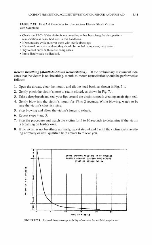
Rescue Breathing (Mouth-to-Mouth Resuscitation). If the preliminary assessment indi-cates that the victim is not breathing, mouth-to-mouth resuscitation should be performed asfollows:
1. Open the airway, clear the mouth, and tilt the head back, as shown in Fig. 7.1.
2. Gently pinch the victim’s nose to seal it closed, as shown in Fig. 7.4.
3. Take a deep breath and seal your lips around the victim’s mouth creating an air-tight seal.
4. Gently blow into the victim’s mouth for 11/2 to 2 seconds. While blowing, watch to besure the victim’s chest is rising.
5. Stop blowing and allow the victim’s lungs to exhale.
6. Repeat steps 4 and 5.
7. Stop the procedure and watch the victim for 5 to 10 seconds to determine if the victimis breathing on his/her own.
8. If the victim is not breathing normally, repeat steps 4 and 5 until the victim starts breath-ing normally or until qualified help arrives to relieve you.
ACCIDENT PREVENTION, ACCIDENT INVESTIGATION, RESCUE, AND FIRST AID 7.13
TABLE 7.13 First Aid Procedures for Unconscious Electric Shock Victims with Symptoms
• Check the ABCs. If the victim is not breathing or has heart irregularities, perform resuscitation as described later in this handbook.
• If wounds are evident, cover them with sterile dressings.• If external burns are evident, they should be cooled using clear, pure water. • Try to cool burns with sterile compresses.• Immediately seek medical aid.
FIGURE 7.3 Elapsed time versus possibility of success for artificial respiration.
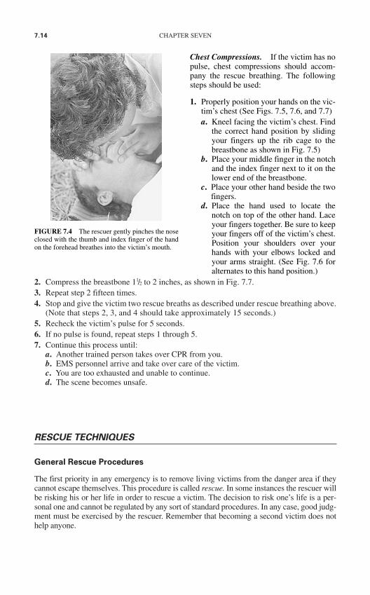
7.14 CHAPTER SEVEN
2. Compress the breastbone 11/2 to 2 inches, as shown in Fig. 7.7. 3. Repeat step 2 fifteen times.4. Stop and give the victim two rescue breaths as described under rescue breathing above.
(Note that steps 2, 3, and 4 should take approximately 15 seconds.)5. Recheck the victim’s pulse for 5 seconds. 6. If no pulse is found, repeat steps 1 through 5. 7. Continue this process until:
a. Another trained person takes over CPR from you.b. EMS personnel arrive and take over care of the victim.c. You are too exhausted and unable to continue. d. The scene becomes unsafe.
RESCUE TECHNIQUES
General Rescue Procedures
The first priority in any emergency is to remove living victims from the danger area if theycannot escape themselves. This procedure is called rescue. In some instances the rescuer willbe risking his or her life in order to rescue a victim. The decision to risk one’s life is a per-sonal one and cannot be regulated by any sort of standard procedures. In any case, good judg-ment must be exercised by the rescuer. Remember that becoming a second victim does nothelp anyone.
FIGURE 7.4 The rescuer gently pinches the noseclosed with the thumb and index finger of the handon the forehead breathes into the victim’s mouth.
Chest Compressions. If the victim has nopulse, chest compressions should accom-pany the rescue breathing. The followingsteps should be used:
1. Properly position your hands on the vic-tim’s chest (See Figs. 7.5, 7.6, and 7.7)a. Kneel facing the victim’s chest. Find
the correct hand position by slidingyour fingers up the rib cage to thebreastbone as shown in Fig. 7.5)
b. Place your middle finger in the notchand the index finger next to it on thelower end of the breastbone.
c. Place your other hand beside the twofingers.
d. Place the hand used to locate thenotch on top of the other hand. Laceyour fingers together. Be sure to keepyour fingers off of the victim’s chest.Position your shoulders over yourhands with your elbows locked andyour arms straight. (See Fig. 7.6 foralternates to this hand position.)
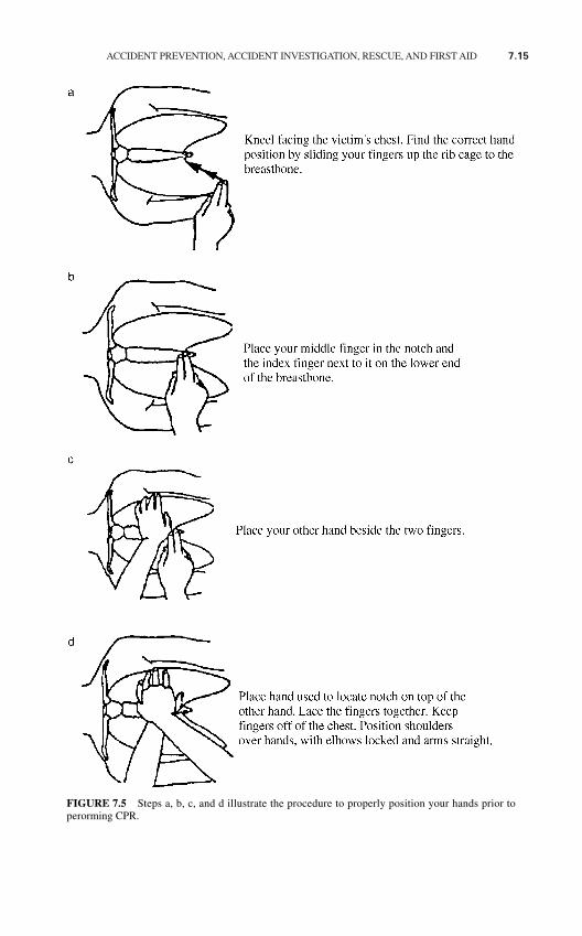
ACCIDENT PREVENTION, ACCIDENT INVESTIGATION, RESCUE, AND FIRST AID 7.15
FIGURE 7.5 Steps a, b, c, and d illustrate the procedure to properly position your hands prior toperorming CPR.
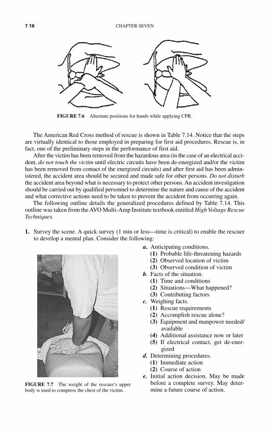
The American Red Cross method of rescue is shown in Table 7.14. Notice that the stepsare virtually identical to those employed in preparing for first aid procedures. Rescue is, infact, one of the preliminary steps in the performance of first aid.
After the victim has been removed from the hazardous area (in the case of an electrical acci-dent, do not touch the victim until electric circuits have been de-energized and/or the victimhas been removed from contact of the energized circuits) and after first aid has been admin-istered, the accident area should be secured and made safe for other persons. Do not disturbthe accident area beyond what is necessary to protect other persons. An accident investigationshould be carried out by qualified personnel to determine the nature and cause of the accidentand what corrective actions need to be taken to prevent the accident from occurring again.
The following outline details the generalized procedures defined by Table 7.14. Thisoutline was taken from the AVO Multi-Amp Institute textbook entitled High Voltage RescueTechniques.
1. Survey the scene. A quick survey (1 min or less—time is critical) to enable the rescuerto develop a mental plan. Consider the following:
7.16 CHAPTER SEVEN
FIGURE 7.6 Alternate positions for hands while applying CPR.
FIGURE 7.7 The weight of the rescuer’s upperbody is used to compress the chest of the victim.
a. Anticipating conditions.(1) Probable life-threatening hazards(2) Observed location of victim(3) Observed condition of victim
b. Facts of the situation.(1) Time and conditions(2) Situations—What happened?(3) Contributing factors
c. Weighing facts.(1) Rescue requirements(2) Accomplish rescue alone?(3) Equipment and manpower needed/
available(4) Additional assistance now or later(5) If electrical contact, get de-ener-
gizedd. Determining procedures.
(1) Immediate action(2) Course of action
e. Initial action decision. May be madebefore a complete survey. May deter-mine a future course of action.
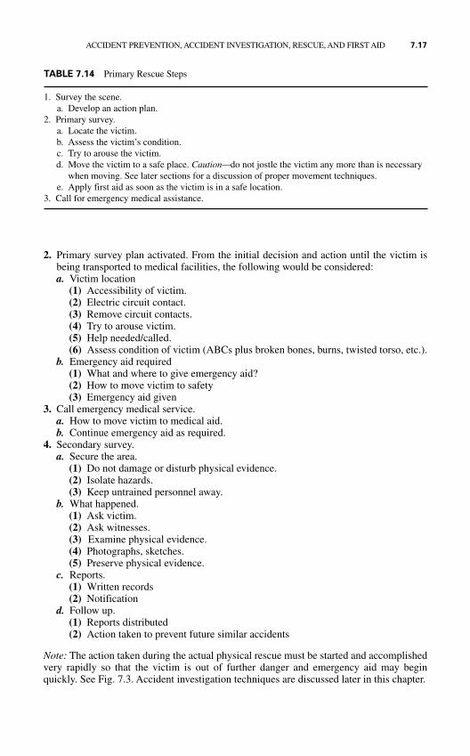
2. Primary survey plan activated. From the initial decision and action until the victim isbeing transported to medical facilities, the following would be considered:a. Victim location
(1) Accessibility of victim.(2) Electric circuit contact.(3) Remove circuit contacts.(4) Try to arouse victim.(5) Help needed/called.(6) Assess condition of victim (ABCs plus broken bones, burns, twisted torso, etc.).
b. Emergency aid required(1) What and where to give emergency aid?(2) How to move victim to safety(3) Emergency aid given
3. Call emergency medical service.a. How to move victim to medical aid.b. Continue emergency aid as required.
4. Secondary survey.a. Secure the area.
(1) Do not damage or disturb physical evidence.(2) Isolate hazards.(3) Keep untrained personnel away.
b. What happened.(1) Ask victim.(2) Ask witnesses.(3) Examine physical evidence.(4) Photographs, sketches.(5) Preserve physical evidence.
c. Reports.(1) Written records(2) Notification
d. Follow up.(1) Reports distributed(2) Action taken to prevent future similar accidents
Note: The action taken during the actual physical rescue must be started and accomplishedvery rapidly so that the victim is out of further danger and emergency aid may beginquickly. See Fig. 7.3. Accident investigation techniques are discussed later in this chapter.
ACCIDENT PREVENTION, ACCIDENT INVESTIGATION, RESCUE, AND FIRST AID 7.17
TABLE 7.14 Primary Rescue Steps
1. Survey the scene.a. Develop an action plan.
2. Primary survey.a. Locate the victim.b. Assess the victim’s condition.c. Try to arouse the victim.d. Move the victim to a safe place. Caution—do not jostle the victim any more than is necessary
when moving. See later sections for a discussion of proper movement techniques.e. Apply first aid as soon as the victim is in a safe location.
3. Call for emergency medical assistance.
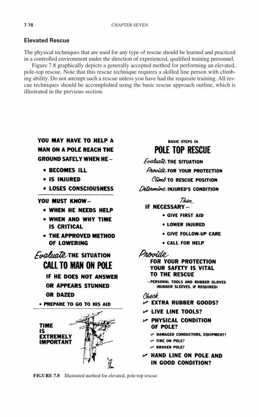
7.18 CHAPTER SEVEN
Elevated Rescue
The physical techniques that are used for any type of rescue should be learned and practicedin a controlled environment under the direction of experienced, qualified training personnel.
Figure 7.8 graphically depicts a generally accepted method for performing an elevated,pole-top rescue. Note that this rescue technique requires a skilled line person with climb-ing ability. Do not attempt such a rescue unless you have had the requisite training. All res-cue techniques should be accomplished using the basic rescue approach outline, which isillustrated in the previous section.
FIGURE 7.8 Illustrated method for elevated, pole-top rescue.
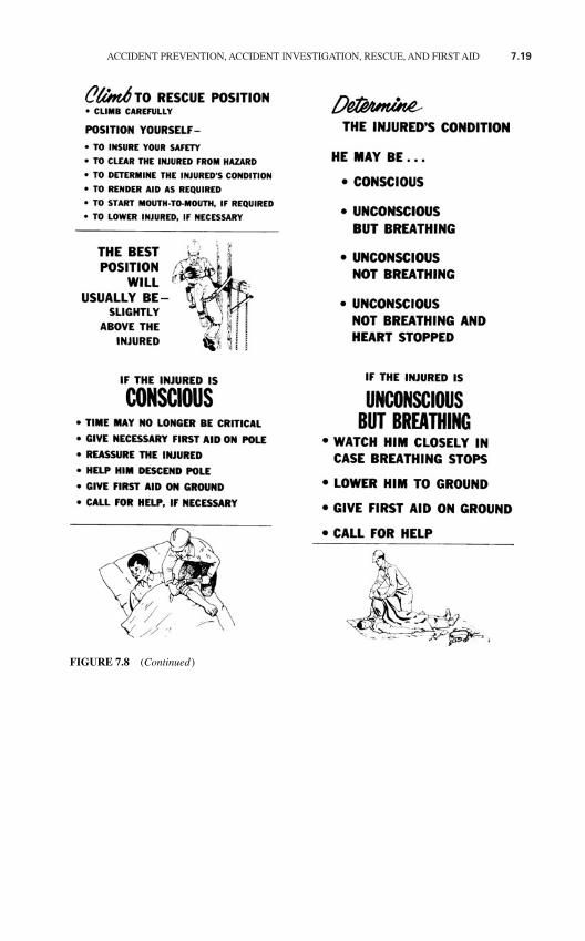
ACCIDENT PREVENTION, ACCIDENT INVESTIGATION, RESCUE, AND FIRST AID 7.19
FIGURE 7.8 (Continued)
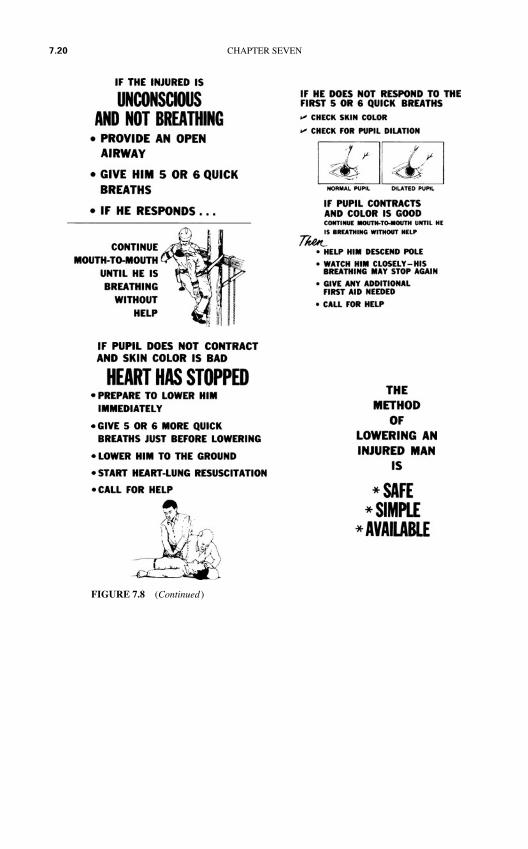
7.20 CHAPTER SEVEN
FIGURE 7.8 (Continued)
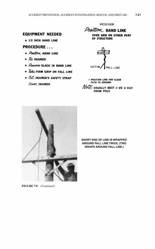
ACCIDENT PREVENTION, ACCIDENT INVESTIGATION, RESCUE, AND FIRST AID 7.21
FIGURE 7.8 (Continued)
SHORT END OF LINE IS WRAPPEDAROUND FALL LINE TWICE. (TWO
WRAPS AROUND FALL LINE.)
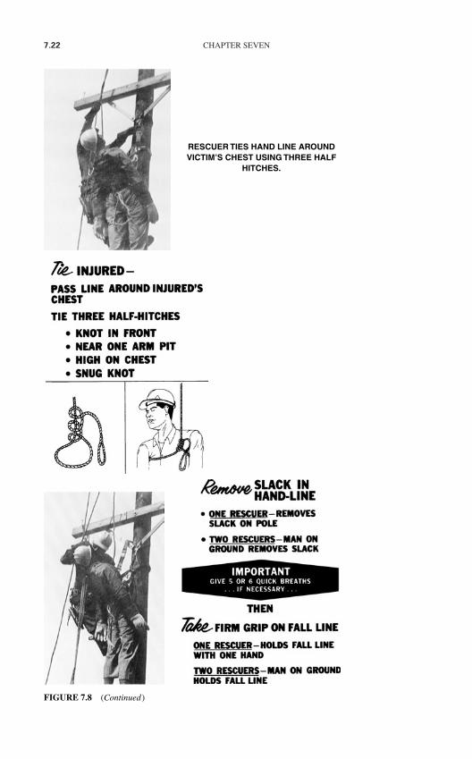
7.22 CHAPTER SEVEN
RESCUER TIES HAND LINE AROUNDVICTIM’S CHEST USING THREE HALF
HITCHES.
FIGURE 7.8 (Continued)
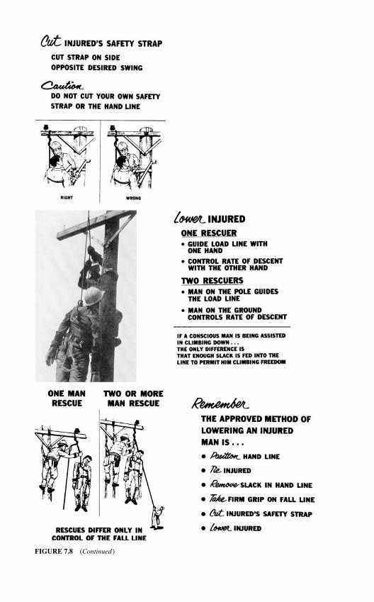
FIGURE 7.8 (Continued)

7.24 CHAPTER SEVEN
LAY VICTIM ON HIS BACK AND OBSERVE IF VICTIM IS CONSCIOUS.IF VICTIM IS CONSCIOUS,TIME MAY NO LONGER BE CRITICAL. GIVE NECESSARY FIRST AID. CALL FOR HELP.
LINE MUST BE REMOVED ANDVICTIM EASED ON
TO GROUND
FIGURE 7.8 (Continued)

ACCIDENT PREVENTION, ACCIDENT INVESTIGATION, RESCUE, AND FIRST AID 7.25
IF THE INJURED IS UNCONSCIOUS ANDNOT BREATHING, PROVIDE AN OPEN AIR-WAY. GIVE HIM FIVE OR SIX QUICKBREATHS. IF HE RESPONDS, CONTINUEMOUTH-TO-MOUTH RESUSCITATIONUNTIL HE IS BREATHING WITHOUT HELP. IF NO PULSE IS PRESENT, PUPILDOES NOT CONTRACT, AND SKIN COLOR IS NOT NORMAL, HIS HEART HAS STOPPED. RESTORE CIRCULATION.USE HEART-LUNG RESUSCITATION.
BUCKET TRUCKRESCUE
TIMEIS
CRITICAL
EQUIP PORTION OF INSULATED BOOMOF TRUCK WITH ROPE BLOCKS
DESIGNED FOR HOT-LINE WORK.
FIGURE 7.8 (Continued)
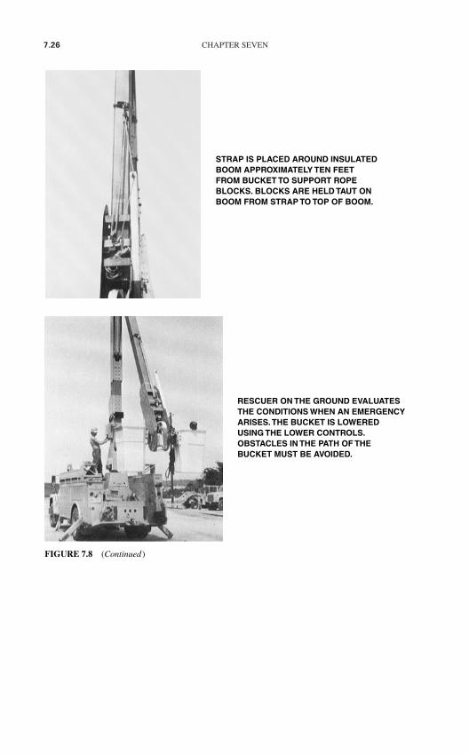
7.26 CHAPTER SEVEN
STRAP IS PLACED AROUND INSULATEDBOOM APPROXIMATELY TEN FEET FROM BUCKET TO SUPPORT ROPEBLOCKS. BLOCKS ARE HELD TAUT ONBOOM FROM STRAP TO TOP OF BOOM.
RESCUER ON THE GROUND EVALUATESTHE CONDITIONS WHEN AN EMERGENCYARISES.THE BUCKET IS LOWERED USING THE LOWER CONTROLS.OBSTACLES IN THE PATH OF THE BUCKET MUST BE AVOIDED.
FIGURE 7.8 (Continued)

ACCIDENT PREVENTION, ACCIDENT INVESTIGATION, RESCUE, AND FIRST AID 7.27
HOOK ON ROPE BLOCKS IS ENGAGED IN A RING ON THE LINEMAN’S SAFETYSTRAP. SAFETY STRAP IS RELEASED
FROM BOOM OF TRUCK.
ROPE BLOCKS ARE DRAWN TAUT BYRESCUER ON THE GROUND.
UNCONSCIOUS VICTIM IS RAISED OUTOF BUCKET WITH ROPE BLOCKS.
FIGURE 7.8 (Continued)

7.28 CHAPTER SEVEN
RESCUER EASES VICTIM ON TO THEGROUND. CARE SHOULD BE TAKEN TO PROTECT THE INJURED VICTIM
FROM FURTHER INJURY.
RELEASE ROPE BLOCKS
FROMVICTIM.
FIGURE 7.8 (Continued)
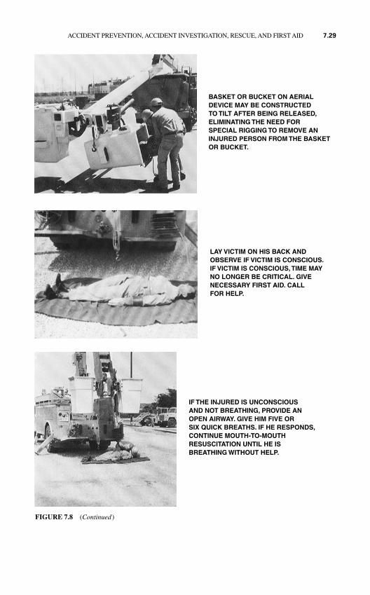
ACCIDENT PREVENTION, ACCIDENT INVESTIGATION, RESCUE, AND FIRST AID 7.29
BASKET OR BUCKET ON AERIALDEVICE MAY BE CONSTRUCTED TO TILT AFTER BEING RELEASED,ELIMINATING THE NEED FOR SPECIAL RIGGING TO REMOVE ANINJURED PERSON FROM THE BASKETOR BUCKET.
LAY VICTIM ON HIS BACK ANDOBSERVE IF VICTIM IS CONSCIOUS.IF VICTIM IS CONSCIOUS,TIME MAY NO LONGER BE CRITICAL. GIVE NECESSARY FIRST AID. CALL FOR HELP.
IF THE INJURED IS UNCONSCIOUS AND NOT BREATHING, PROVIDE ANOPEN AIRWAY. GIVE HIM FIVE OR SIX QUICK BREATHS. IF HE RESPONDS,CONTINUE MOUTH-TO-MOUTH RESUSCITATION UNTIL HE IS BREATHING WITHOUT HELP.
FIGURE 7.8 (Continued)
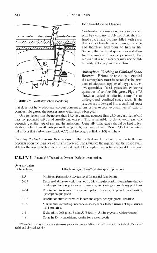
7.30 CHAPTER SEVEN
Confined-Space Rescue
Confined-space rescue is made more com-plex by two basic problems. First, the con-fined space may become filled with gasesthat are not breathable or, worse, are toxicand therefore hazardous to human life.Second, the confined space does not allowfor free motion of rescue personnel. Thismeans that rescue workers may not be ableto easily get a grip on the victim.
Atmosphere Checking in Confined-SpaceRescues. Before the rescue is attempted,the atmosphere must be tested for the pres-ence of adequate supplies of oxygen, exces-sive quantities of toxic gases, and excessivequantities of combustible gases. Figure 7.9shows a typical monitoring setup for anunderground confined-space area. If therescuer must descend into a confined space
that does not have adequate oxygen concentrations or has excessive quantities of toxic orcombustible gases, the rescuer must wear respiration gear.
Oxygen levels must be no less than 19.5 percent and no more than 23.5 percent. Table 7.15lists the potential effects of insufficient oxygen. The permissible levels of toxic gas varydepending on the type of gas and the individual. Generally toxic gases should be kept to lev-els that are less than 50 parts per million (ppm) by volume. Tables 7.16 and 7.17 list the poten-tial effects that carbon monoxide (CO) and hydrogen sulfide (H2S) will have.
Securing the Victim to the Rescue Line. The method used to secure a victim to the linedepends upon the logistics of the given rescue. The nature of the injuries and the space avail-able for the rescue both affect the method used. The simplest way is to tie a hand line around
FIGURE 7.9 Vault atmosphere monitoring.
TABLE 7.15 Potential Effects of an Oxygen-Deficient Atmosphere
Oxygen content (% by volume) Effects and symptoms* (at atmosphere pressure)
19.5 Minimum permissible oxygen level for normal functioning.
15–19 Decreased ability to work strenuously. May impair coordination and may induceearly symptoms in persons with coronary, pulmonary, or circulatory problems.
12–14 Respiration increases in exertion; pulse increases, impaired coordination,perception, judgment.
10–12 Respiration further increases in rate and depth, poor judgment, lips blue.
8–10 Mental failure, fainting, unconsciousness, ashen face, blueness of lips, nausea,and vomiting.
6–8 Eight min, 100% fatal; 6 min, 50% fatal; 4–5 min, recovery with treatment.
4–6 Coma in 40 s, convulsions, respiration ceases, death.
* The effects and symptoms at a given oxygen content are guidelines and will vary with the individual’s state ofhealth and physical activity.
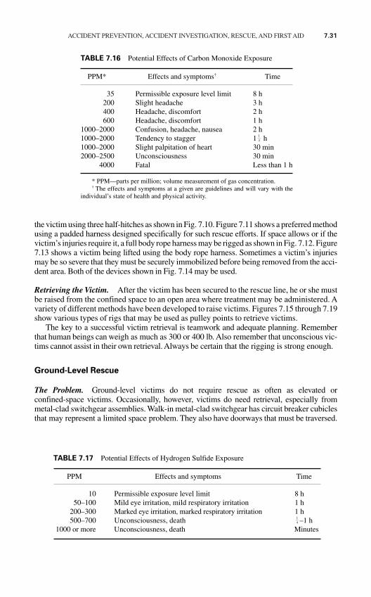
ACCIDENT PREVENTION, ACCIDENT INVESTIGATION, RESCUE, AND FIRST AID 7.31
the victim using three half-hitches as shown in Fig. 7.10. Figure 7.11 shows a preferred methodusing a padded harness designed specifically for such rescue efforts. If space allows or if thevictim’s injuries require it, a full body rope harness may be rigged as shown in Fig. 7.12. Figure7.13 shows a victim being lifted using the body rope harness. Sometimes a victim’s injuriesmay be so severe that they must be securely immobilized before being removed from the acci-dent area. Both of the devices shown in Fig. 7.14 may be used.
Retrieving the Victim. After the victim has been secured to the rescue line, he or she mustbe raised from the confined space to an open area where treatment may be administered. Avariety of different methods have been developed to raise victims. Figures 7.15 through 7.19show various types of rigs that may be used as pulley points to retrieve victims.
The key to a successful victim retrieval is teamwork and adequate planning. Rememberthat human beings can weigh as much as 300 or 400 lb. Also remember that unconscious vic-tims cannot assist in their own retrieval. Always be certain that the rigging is strong enough.
Ground-Level Rescue
The Problem. Ground-level victims do not require rescue as often as elevated orconfined-space victims. Occasionally, however, victims do need retrieval, especially frommetal-clad switchgear assemblies. Walk-in metal-clad switchgear has circuit breaker cubiclesthat may represent a limited space problem. They also have doorways that must be traversed.
TABLE 7.16 Potential Effects of Carbon Monoxide Exposure
PPM* Effects and symptoms† Time
35 Permissible exposure level limit 8 h200 Slight headache 3 h400 Headache, discomfort 2 h600 Headache, discomfort 1 h
1000–2000 Confusion, headache, nausea 2 h1000–2000 Tendency to stagger 1 h1000–2000 Slight palpitation of heart 30 min2000–2500 Unconsciousness 30 min
4000 Fatal Less than 1 h
* PPM—parts per million; volume measurement of gas concentration.† The effects and symptoms at a given are guidelines and will vary with the
individual’s state of health and physical activity.
14
TABLE 7.17 Potential Effects of Hydrogen Sulfide Exposure
PPM Effects and symptoms Time
10 Permissible exposure level limit 8 h50–100 Mild eye irritation, mild respiratory irritation 1 h
200–300 Marked eye irritation, marked respiratory irritation 1 h500–700 Unconsciousness, death –1 h
1000 or more Unconsciousness, death Minutes
14
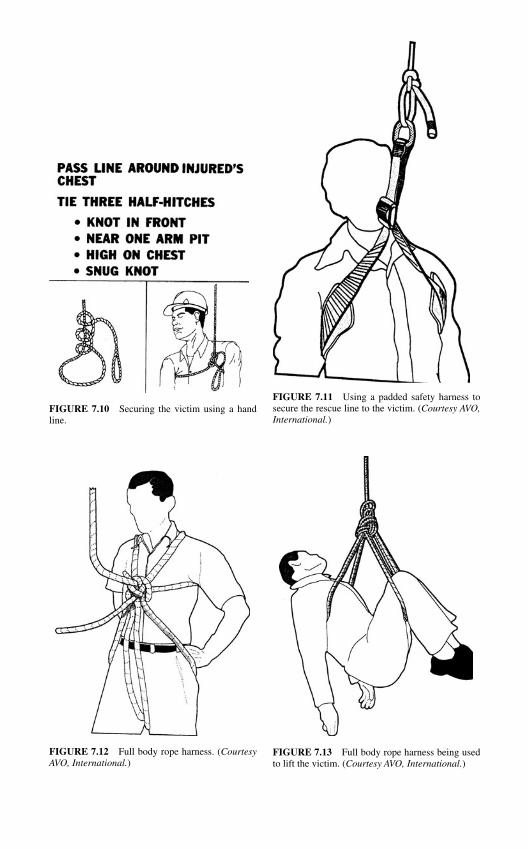
FIGURE 7.10 Securing the victim using a handline.
FIGURE 7.11 Using a padded safety harness tosecure the rescue line to the victim. (Courtesy AVO,International.)
FIGURE 7.12 Full body rope harness. (CourtesyAVO, International.)
FIGURE 7.13 Full body rope harness being usedto lift the victim. (Courtesy AVO, International.)
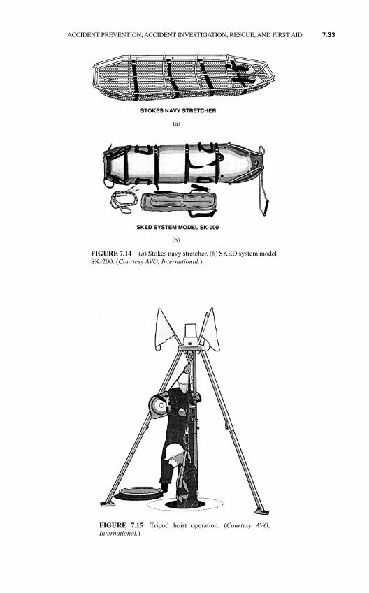
FIGURE 7.14 (a) Stokes navy stretcher. (b) SKED system modelSK-200. (Courtesy AVO, International.)
FIGURE 7.15 Tripod hoist operation. (Courtesy AVO,International.)
ACCIDENT PREVENTION, ACCIDENT INVESTIGATION, RESCUE, AND FIRST AID 7.33
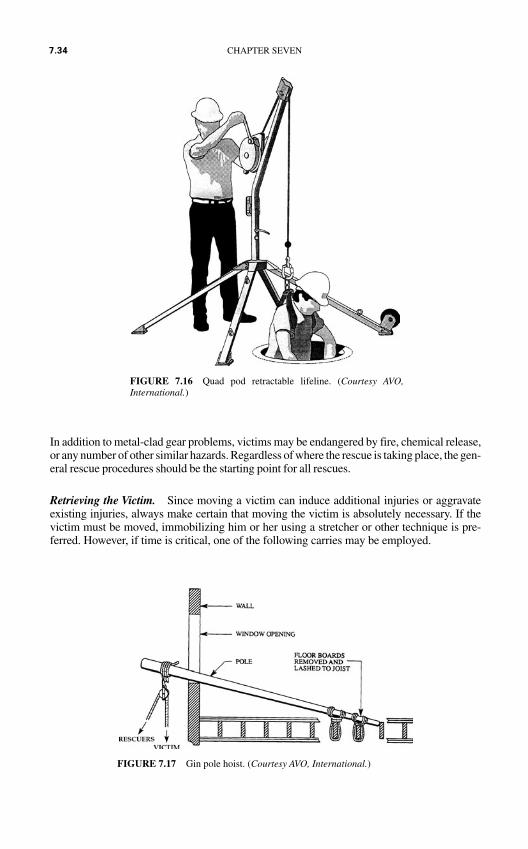
In addition to metal-clad gear problems, victims may be endangered by fire, chemical release,or any number of other similar hazards. Regardless of where the rescue is taking place, the gen-eral rescue procedures should be the starting point for all rescues.
Retrieving the Victim. Since moving a victim can induce additional injuries or aggravateexisting injuries, always make certain that moving the victim is absolutely necessary. If thevictim must be moved, immobilizing him or her using a stretcher or other technique is pre-ferred. However, if time is critical, one of the following carries may be employed.
FIGURE 7.16 Quad pod retractable lifeline. (Courtesy AVO,International.)
FIGURE 7.17 Gin pole hoist. (Courtesy AVO, International.)
7.34 CHAPTER SEVEN
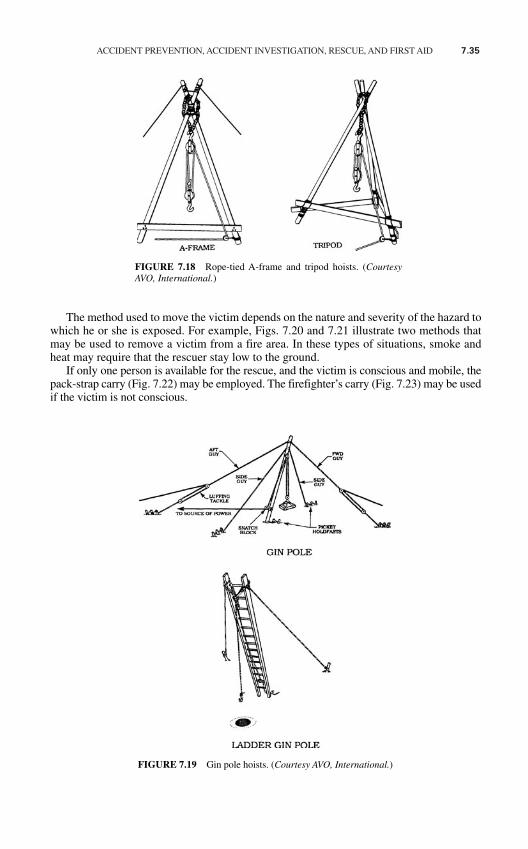
ACCIDENT PREVENTION, ACCIDENT INVESTIGATION, RESCUE, AND FIRST AID 7.35
The method used to move the victim depends on the nature and severity of the hazard towhich he or she is exposed. For example, Figs. 7.20 and 7.21 illustrate two methods thatmay be used to remove a victim from a fire area. In these types of situations, smoke andheat may require that the rescuer stay low to the ground.
If only one person is available for the rescue, and the victim is conscious and mobile, thepack-strap carry (Fig. 7.22) may be employed. The firefighter’s carry (Fig. 7.23) may be usedif the victim is not conscious.
FIGURE 7.18 Rope-tied A-frame and tripod hoists. (CourtesyAVO, International.)
FIGURE 7.19 Gin pole hoists. (Courtesy AVO, International.)
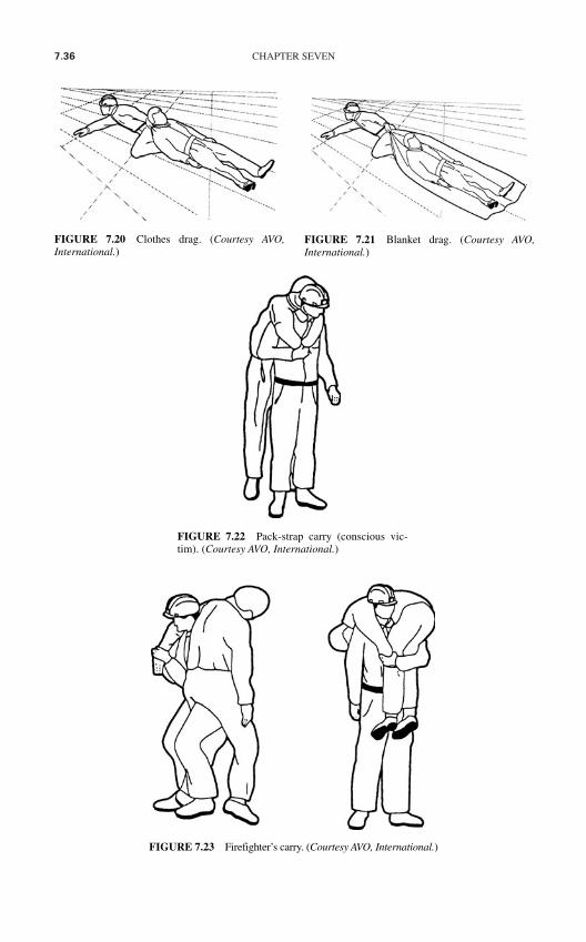
7.36 CHAPTER SEVEN
FIGURE 7.22 Pack-strap carry (conscious vic-tim). (Courtesy AVO, International.)
FIGURE 7.23 Firefighter’s carry. (Courtesy AVO, International.)
FIGURE 7.20 Clothes drag. (Courtesy AVO,International.)
FIGURE 7.21 Blanket drag. (Courtesy AVO,International.)
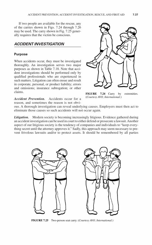
ACCIDENT PREVENTION, ACCIDENT INVESTIGATION, RESCUE, AND FIRST AID 7.37
If two people are available for the rescue, anyof the carries shown in Figs. 7.24 through 7.26may be used. The carry shown in Fig. 7.25 gener-ally requires that the victim be conscious.
ACCIDENT INVESTIGATION
Purpose
When accidents occur, they must be investigatedthoroughly. An investigation serves two majorpurposes as shown in Table 7.18. Note that acci-dent investigations should be performed only byqualified professionals who are experienced insuch matters. Litigation can often ensue and resultin corporate, personal, or product liability; errorsand omissions; insurance subrogation; or otherclaims.
Accident Prevention. Accidents occur for areason, and sometimes the reason is not obvi-ous. A thorough investigation can reveal underlying causes. Employers must then act toeliminate those causes so such accidents will not occur again.
Litigation. Modern society is becoming increasingly litigious. Evidence gathered duringan accident investigation can be used in court to either defend or prosecute a lawsuit.Anotheraspect of our litigious society is the tendency of companies and individuals to “keep every-thing secret until the attorney approves it.” Sadly, this approach may seem necessary to pre-vent frivolous lawsuits and/or to protect assets. It should be remembered by all parties
FIGURE 7.24 Carry by extremities.(Courtesy AVO, International.)
FIGURE 7.25 Two-person seat carry. (Courtesy AVO, International.)
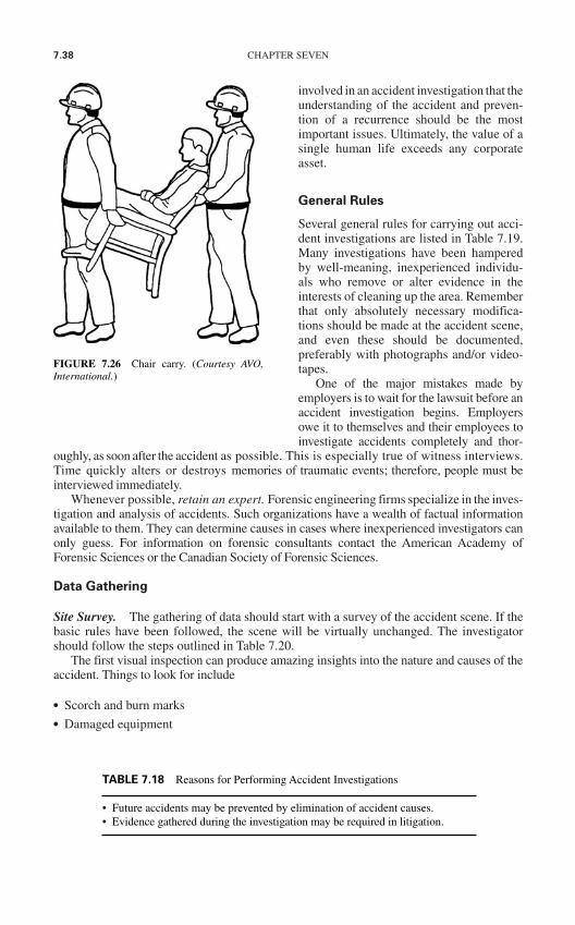
7.38 CHAPTER SEVEN
involved in an accident investigation that theunderstanding of the accident and preven-tion of a recurrence should be the mostimportant issues. Ultimately, the value of asingle human life exceeds any corporateasset.
General Rules
Several general rules for carrying out acci-dent investigations are listed in Table 7.19.Many investigations have been hamperedby well-meaning, inexperienced individu-als who remove or alter evidence in theinterests of cleaning up the area. Rememberthat only absolutely necessary modifica-tions should be made at the accident scene,and even these should be documented,preferably with photographs and/or video-tapes.
One of the major mistakes made byemployers is to wait for the lawsuit before anaccident investigation begins. Employersowe it to themselves and their employees toinvestigate accidents completely and thor-
oughly, as soon after the accident as possible. This is especially true of witness interviews.Time quickly alters or destroys memories of traumatic events; therefore, people must beinterviewed immediately.
Whenever possible, retain an expert. Forensic engineering firms specialize in the inves-tigation and analysis of accidents. Such organizations have a wealth of factual informationavailable to them. They can determine causes in cases where inexperienced investigators canonly guess. For information on forensic consultants contact the American Academy ofForensic Sciences or the Canadian Society of Forensic Sciences.
Data Gathering
Site Survey. The gathering of data should start with a survey of the accident scene. If thebasic rules have been followed, the scene will be virtually unchanged. The investigatorshould follow the steps outlined in Table 7.20.
The first visual inspection can produce amazing insights into the nature and causes of theaccident. Things to look for include
Scorch and burn marks Damaged equipment
FIGURE 7.26 Chair carry. (Courtesy AVO,International.)
TABLE 7.18 Reasons for Performing Accident Investigations
• Future accidents may be prevented by elimination of accident causes.• Evidence gathered during the investigation may be required in litigation.
ACCIDENT PREVENTION, ACCIDENT INVESTIGATION, RESCUE, AND FIRST AID 7.39
Evidence of safety equipment Position of victim and or objects
The photographs or videotape, preferably both, can permanently store vital evidence.Because of the two-dimensional nature of photography, shots should be taken from all anglesincluding from above to get a complete perspective. A scale reference can be included in thescene.Anaudioorwrittenrecordshouldbemadetoclearlydefinethenatureofeachphotograph,where it was taken, and any specific information that should be noted.
The final detailed inspection and sketch can be handmade, clearly labeled, and dimen-sioned. Dimensions are particularly important since they may prove or disprove the possibilityof any given event during the accident. The sketch should also reference photographs or video-tape evidence that was taken.
Witness Interviews. Witness interviews help to establish what, how, where, and when.However, the investigator must remember that of all the evidence he or she will gather, eye-witness accounts are the least reliable. Human beings tend to be influenced by their own per-sonal backgrounds and prejudices. Within a few hours, or even minutes, of the accident, eyewitnesses’memories start to modify. Witnesses should be interviewed as soon as possible andon audiotape if possible.
The cautions in the previous paragraph are especially true of the accident victim. Thehuman mind will literally shut off to prevent the agony associated with an accident. In caseafter case, victims remember nothing regarding several hours or even days before and afterthe accident. Information supplied by a victim should always be viewed with skepticism.The more traumatic the injury, the less credible will be the victim’s statement.
When interviewing witnesses, the following points should be followed:
When possible, conduct the interview at the accident site. The familiar surroundings mayhelp to arouse memories that would be lost.
Prepare a series of questions to be asked before the interview, and start with these ques-tions. If the witness seems more comfortable with a freewheeling statement, allow it; how-ever, avoid rambling and nonrelevant statements since these will only cloud the results.
TABLE 7.19 General Rules for Performance of an Accident Investigation
• Investigations should be performed only by qualified, experienced personnel.• Until the investigation is complete, the accident scene should be modified only to the extent
necessary to eliminate immediate hazards to personnel.• No evidence should be destroyed or thrown away for at least 5 to 10 years after the accident.• Photograph everything from many different angles.• Document everything that is observed or taken in interviews.• Perform the investigation as soon as possible. Remember that human memory is volatile.
TABLE 7.20 Steps for an Accident Site Survey
• Visually inspect the area, making notes about general observations.• Photograph or videotape the scene.• Make a detailed inspection and develop a sketch of the entire scene.
7.40 CHAPTER SEVEN
Try to keep the witness focused on the facts of the case. Blame, fault, and other such sub-jective conclusions should be left to the analysis stage of the investigation.
When the interview is completed, the interview notes should be carefully stored anddated. If you make a summary of the interview, it should be stored with the notes; how-ever, it should not replace the interview notes.
Arrange for a follow-up interview to deal with questionable or conflicting accounts.
Physical Evidence. One of the most frequent mistakes made by inexperienced investiga-tors is the alteration, destruction, or loss of physical evidence. A scorched or melted wire,a bit of flaked insulation, a piece of torn cloth, or a damaged circuit breaker can all beextremely important evidence.
Physical evidence should be documented in the preliminary stages of the investigationby the use of photographs, sketches, and written notes. After it has been documented, itshould be carefully marked and stored. Physical evidence should be kept for a minimum of5 years and possibly as long as 10 years depending upon the circumstances of the accident.
Accident Analysis
After the evidence has been gathered and the interviews have been taken, the analysis phasebegins. The actual steps taken in this portion depend to a large extent on the specifics of theaccident itself. However, at least two major steps may be involved.
Experimentation. Actual experimentation includes tests that are performed to evaluate orsimulate certain conditions during an accident. For example, pork can be subjected to elec-tric currents to evaluate the degree of burning that occurs for various currents, electric arcscan be staged with manikins to determine the degree of thermal burning that may occur, andair gaps can be checked to see how far an arc will jump in given circumstances.Experimentation is a detailed and sophisticated procedure and should be performed only byorganizations with the necessary expertise.
Report. A report is developed based on a comprehensive analysis of all the evidence andexperimental data that has been gathered. The report should contain, at a minimum, the sec-tions listed in Table 7.21.
Overview. This section should include an executive summary type of description of theevents leading up to the accident, the accident itself, and the accident aftermath. Onlyvery general information should be included, such as the number of injured persons, thebasic cause of the injuries, and the generalized suggestions for preventing such a prob-lem in the future.
Step-by-step description of the accident. Here the investigator takes the reader througheach step of the accident from beginning to end. All the physical evidence is discussed,
TABLE 7.21 Major Elements of the Final Report of an Accident Investigation
• Overview• Step-by-step description of the accident• Conclusion• Appendices

ACCIDENT PREVENTION, ACCIDENT INVESTIGATION, RESCUE, AND FIRST AID 7.41
and eyewitness accounts are integrated into this portion of the report. All relevant infor-mation should be included, such as the activities of the victim prior to the accident thatmay have affected his or her behavior, the specific actions of the victim during the acci-dent, the safety equipment that was in use at the time, the actions of witnesses, the dura-tion of the electrical contact, the points on the body that were contacted, and other suchdetails.
Conclusion. The investigator should provide an evaluation of the accident includingsuch information as the steps that could be taken to prevent similar accidents in the future,changes in safety equipment or rules that may be indicated, changes in employee train-ing that may be required, and/or changes in work procedures that may be indicated. Sincethis is an engineering report, the investigator should avoid comments about who may beresponsible for the accident. Such issues are better left to the legal system.
Appendices. All the collected data can be included for reference. Remember that othersmay draw different conclusions than that of the investigator and should, therefore, be giventhe advantage of being able to examine all the evidence that has been collected. In addition,the evidence must be present to support the conclusions drawn. Do not include the originalsof photographs and videotapes. Only copies should be included.The originals should be keptin a secure location such as a locked file cabinet or a safe-deposit box. Of course, physicalevidence should not be included except at a formal presentation of the report. However, pho-tographs of physical evidence can be included.
Please note that any and all content of such a report will be subject to insurance contractdirectives; insurance adjusters instructions; attorney-client privilege; powers granted toworker’s compensation investigators; and powers granted to federal, state, and provincialagencies that have jurisdiction in the investigations.

This page intentionally left blank
CHAPTER 8MEDICAL ASPECTS OFELECTRICAL TRAUMA
INTRODUCTION
This handbook serves as a reference on how to be safe around electrical energy. In this chap-ter, the consequences of an electrical safety failure are presented from a medical point of view.
As noted in the Preface, each year many people are killed or injured by electrical energy.In the vast majority of these events, the individuals involved never realized how their timeon the job might change their lives.
STATISTICAL SURVEY
Numbers give a statistical picture of known electrical injuries and fatalities. PublishedU.S. National Institute of Occupational Safety and Health (NIOSH), analyses of the U.S.Department of Labor (DOL), Bureau of Labor Statistics (BLS), and data on electricalincidents by Cawley and Homce show, from 1992 to 1998, in the United States, 32,309employees were injured in electrical events resulting in days away from work, while 2,267people died because of an occupational contact exposure to power frequency electricalenergy.1
Cawley and Homce further analyzed 623 fatalities, and found that the incident voltagein 87 percent of the fatality reports was noted as 15,000 V or less, with 32 percent of thefatalities noted during work on 0-600 V (Table 8.1). Overhead power lines were an electri-cal source in about 40 percent of the deaths.
From 1980–1995, in the United States, electrocution accounted for 7.1 percent ofoccupational deaths among men, and 0.7 percent among women.2 Among young work-ers, electrocution was the cause of 12 percent of all workplace deaths, and the third lead-ing cause of work-related deaths among 16- and 17-year olds, after motor vehicle deathsand workplace homicide.3
While comprising about 7 percent of the U.S. workforce, construction workers sus-tained 44 percent of electrical fatalities.1 Figure 8.1 illustrates possible electrical exposurehazards on a construction work site with a crane truck and overhead power line nearby4. Inthe illustration, electrical current flows from the power line through the truck to contactsbetween the truck tires and earth, (“step potential” hazard) and the truck and worker (“touchpotential” hazard) while the worker is standing on the earth.
Focusing on electrical fatalities among U.S. construction workers, the researchers Ore& Casini studied 1980–1991 data, showing the age distribution of those construction
8.1
Copyright © 2006 by The McGraw-Hill Companies, Inc. Click here for terms of use.
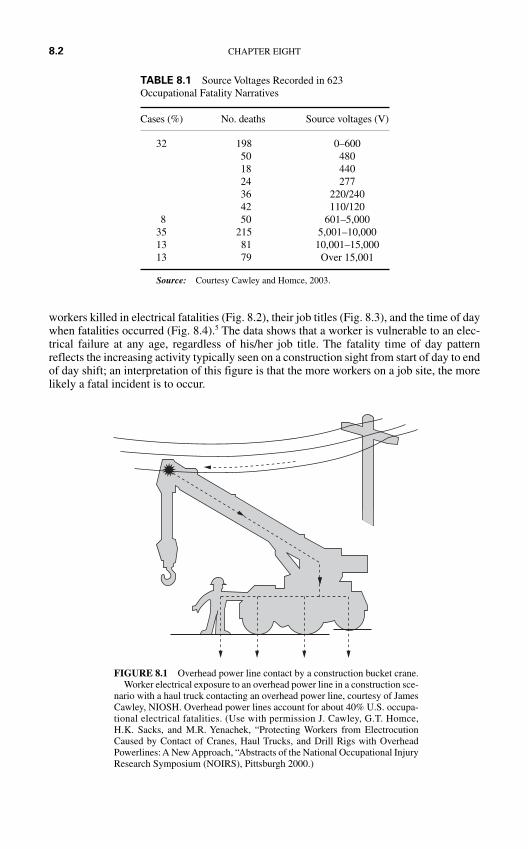
workers killed in electrical fatalities (Fig. 8.2), their job titles (Fig. 8.3), and the time of daywhen fatalities occurred (Fig. 8.4).5 The data shows that a worker is vulnerable to an elec-trical failure at any age, regardless of his/her job title. The fatality time of day patternreflects the increasing activity typically seen on a construction sight from start of day to endof day shift; an interpretation of this figure is that the more workers on a job site, the morelikely a fatal incident is to occur.
8.2 CHAPTER EIGHT
TABLE 8.1 Source Voltages Recorded in 623Occupational Fatality Narratives
Cases (%) No. deaths Source voltages (V)
32 198 0–60050 48018 44024 27736 220/24042 110/120
8 50 601–5,00035 215 5,001–10,00013 81 10,001–15,00013 79 Over 15,001
Source: Courtesy Cawley and Homce, 2003.
FIGURE 8.1 Overhead power line contact by a construction bucket crane.Worker electrical exposure to an overhead power line in a construction sce-
nario with a haul truck contacting an overhead power line, courtesy of JamesCawley, NIOSH. Overhead power lines account for about 40% U.S. occupa-tional electrical fatalities. (Use with permission J. Cawley, G.T. Homce,H.K. Sacks, and M.R. Yenachek, “Protecting Workers from ElectrocutionCaused by Contact of Cranes, Haul Trucks, and Drill Rigs with OverheadPowerlines: A New Approach, “Abstracts of the National Occupational InjuryResearch Symposium (NOIRS), Pittsburgh 2000.)
Considering construction fatalities from another angle, when U.S. construction cranefatalities for 1984–1994 were studied by Suruda and colleagues, 196 of 502 fatalities, or39 percent, involved electrocution.6
Often the question is asked, “Do electrical fatalities or injuries mostly occur in peoplenew to their jobs?” This is a question that tries to sort out differences in the fatality trends
MEDICAL ASPECTS OF ELECTRICAL TRAUMA 8.3
FIGURE 8.2 Distribution of electrical fatalities among U.S. construction workers, 1980–1991.Adapted from Figure 2 from Ore & Casini’s 1996 report, this illustration shows the number ofdeaths per 100,000 workers by age groups. Courtesy of T. Ore, and V. Casini, “Electrical FatalitiesAmong U.S. Construction Workers,” JOEM, vol. 38, no. 6, pp. 587–592, 1996.
FIGURE 8.3 Job titles of electrical fatalities among U.S. construction workers, 1980–1991.Courtesy of T. Ore, and V. Casini, “Electrical Fatalities Among U.S. Construction Workers,JOEM, vol. 38, no. 6, pp. 587–592, 1996.
in relationship to the worker’s job experience, rather than the worker’s age while on thejob. International Brotherhood of Electrical Worker (IBEW) data in part addresses
this question. Power-line-transmission anddistribution-worker fatalities for 1971–1987were previously reported by seniority on thejob (Fig. 8.5). Note that higher seniority sta-tus does not confer protection from an elec-trical fatality.
Non-Occupational Electrical Trauma
Compared to workplace electrical trauma,non-occupational electrical injury and fatal-ity statistics are not collected routinely, lim-iting injury and fatality estimates. Typicallynon-occupational electrical injuries are sus-tained in home or public settings, includinghouseholds, medical facilities, police responsesites, and educational and recreational loca-tions (Table 8.2).7,8,9,10,11
Fatality and Injury Related Costs
Over 1.6 million U.S. employees work in the specialty trades, as shown by 2000 U.S. Censusdata (Table 8.3); the annual value of U.S. construction put in place by type of construction(Table 8.4) is shown for 2002.12 According to a survey research from the Integrated Benefits
8.4 CHAPTER EIGHT
1 2 3 4 5 6 7 8 9 10 11 12 13 14 15 16 17 18 19 20 21 22 23 24
24 hour clock
14
12
10
8
6
4
2
0
%
FIGURE 8.4 Time of day of electrical fatalities among U.S. construction workers, 1980–1991. This figure shows the per centage of U.S. construction electrical fatalities compared across a
24 hour period. Adapted from Ore & Casini. Courtesy of T. Ore, and V. Casini, “ElectricalFatalities Among U.S. Construction Workers,” JOEM, vol. 38, no. 6, pp. 587–592, 1996.
FIGURE 8.5 Power line transmission and distri-bution worker fatality experience by seniority,1975–1988.
This figure shows the distribution of power linefatalities in IBEW linemen form 1975-1988 byyears of seniority. (Courtesy IBEW Transmissionand Distribution Worker Data.)
TABLE 8.2 Non-Occupational Electrical Trauma Scenarios
Setting Source Fatality/injury description
Homes Receptacles 3,900 injuries annually, with 33% young childreninserting metal objects7
Clinical/Hospital Iatrogenic Pectoral muscle damage after defibrillation8
Police Action Stun guns Associated with more than 50 fatalities since 20009
Educational/Recreational Swim pools Electrocutions and Electric Shocks10
Vending Electrocutions, shocks11
TABLE 8.3 Construction Specialty Fabricators and Suppliers, 1997
Dollar valueof business Annual
NAICS Description special done payroll Paid code trade contractors Establishments ($millions) ($millions) employees
2351 Plumbing, heating, and air- 84,876 88,427.4 25,720.2 788,930conditioning contractors
2353 Electrical contractors 61,414 64,915.1 21,680.0 641,98423591 Structural steel erection 4,238 8,152.7 2,387.1 72,301
contractors23592 Glass and glazing contractors 4,713 4,045.5 1,051.6 35,82323594 Wrecking and demolition 1,541 2,304.0 592.2 18,820
contractors23595 Building equipment and other 4,488 9,342.9 3,148.0 75,501
machinery installation contractors
Total 161,270 177,187.7 54,579.0 1,633,359
Source: U.S. Census Bureau, 2000a. Sums may not add to totals due to independent rounding. Taken fromGallaher and O’Conner’s report for the U.S. Dept. of Commerce Technology Administration National Institute ofStandards and Technology Table 1-8, August, 2004 [Gallaher and O’Conner, 2004].
TABLE 8.4. Value of U.S. Construction Put in Place, 2002
Type of construction ($Millions)
Office 37,578Hotels 10,285Religious 8,217Other Commercial 55,879Educational 68,995Hospital and Institutional 22,366Public Housing & Redevelopment 5,507Industrial 18,486Electric Light and Power 24,789Public Utilities 54,370Military 18,284All Other Nonresidential 49,362
Total 374,118
Source: U.S. Census Bureau, 2004b. Taken from Gallaher andO’Conner's report for the U.S. Dept. of Commerce TechnologyAdministration National Institute of Standards and Technology Table1-1, August, 2004 [Gallaher and O’Conner, 2004].
8.5
Institute, including a traditional view of paid benefits, in 2002, workers compensation costs forwork-related injuries and illnesses were estimated at 9 percent of health costs.13 If this 9 per-cent estimate is used along side of the total health costs for the electrical contractors annualpayroll (for example, 1997 figures of $21.7 billion as shown in Table 8.312), the financial lossesfrom workplace injuries and illnesses can be placed in context. Drawing on the most recentlyavailable national data from 1993, depending on the state, the annualized U.S. workers com-pensation cost may range from $573 to $1,979 per worker employed.14
ELECTRICAL EVENTS
An electrical event may scale from an almost unnoticeable release of energy, like localizedheating in a conductor or a very brief light flash in a low voltage installation, to a massiveexplosion from an escalating arcing fault in a multiphase high voltage system.
Consider when the electrical energy release in an event is relatively small and slow, asfor example, with ohmic heating in a fluorescent fixture’s ballast. The electrical hazard canlead to a potentially fatal consequence if it serves as an ignition source in the presence ofcombustible dust, vapor, or materials. Fires and explosions from combustion of these haz-ardous materials can follow.
Another scenario can occur when an employee comes in an unprotected contact with anelectrical shock hazard. Then electrical energy can flow from the hazard to the employee,essentially as if the employee has become a part of the source circuit. The employee’s connec-tion to the circuit can be “in series,” as when current flows “into” or “through” the body; or theconnection to the circuit can be “in parallel,” as when current flows over the employee withoutcreating a potential electrical gradient across specific tissues in the body. Complex connectionin both series and parallel paths may occur as well.
A third scenario is when an employee or equipment the employee is using enters an air gapbetween conductors. This may happen initially intentionally as, for example, in the high volt-age scenario of live-line work. Another possibility is that the employee or their equipment mayenter the air gap between conductors initially accidentally, as with the operation of equipmenttoo near to a power line. As a result of entry into an air gap between conductors, a conductivechannel can open between the source and the employee or their tool, resulting in an electricalarc fault. With an electrical arc fault, a large amount of electrical energy can flow in an ultra-short time, creating an event that transforms electrical energy into multiple forms of energyflowing from the source into the electrical event space.
As suggested in the chapter on the hazards of electricity, an electrical event can be for-mally described using:
the equipment voltage and involved current. the occurrence of an outage resulting in disruption of service, manufacturing, or indus-
trial process; or the destructive effects of the energy released in the incident.
As earlier discussions about the National Electrical Code (NEC) have indicated, hazardrating of electrical installations is variable, depending on the location of the installation aswell as on the surrounding operations and conditions. While there is consensus on how torate electrical installations, there is no widely agreed upon scheme to rate an event’s elec-trical failure severity.
As a general guide, the National Fire Protection Association’s (NFPA) Failure Mode andEffects Analysis (FMEA) can be used as a qualitative rating from 0 to 4, where 0 is for anevent where the hazards result in no effect; a rating of 1 suggests a slight effect; a rating of
8.6 CHAPTER EIGHT
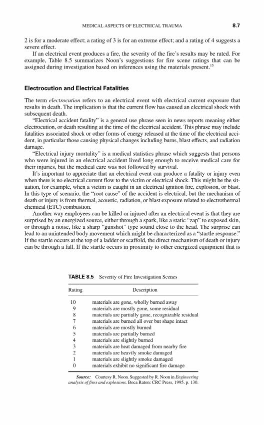
2 is for a moderate effect; a rating of 3 is for an extreme effect; and a rating of 4 suggests asevere effect.
If an electrical event produces a fire, the severity of the fire’s results may be rated. Forexample, Table 8.5 summarizes Noon’s suggestions for fire scene ratings that can beassigned during investigation based on inferences using the materials present.15
Electrocution and Electrical Fatalities
The term electrocution refers to an electrical event with electrical current exposure thatresults in death. The implication is that the current flow has caused an electrical shock withsubsequent death.
“Electrical accident fatality” is a general use phrase seen in news reports meaning eitherelectrocution, or death resulting at the time of the electrical accident. This phrase may includefatalities associated shock or other forms of energy released at the time of the electrical acci-dent, in particular those causing physical changes including burns, blast effects, and radiationdamage.
“Electrical injury mortality” is a medical statistics phrase which suggests that personswho were injured in an electrical accident lived long enough to receive medical care fortheir injuries, but the medical care was not followed by survival.
It’s important to appreciate that an electrical event can produce a fatality or injury evenwhen there is no electrical current flow to the victim or electrical shock. This might be the sit-uation, for example, when a victim is caught in an electrical ignition fire, explosion, or blast.In this type of scenario, the “root cause” of the accident is electrical, but the mechanism ofdeath or injury is from thermal, acoustic, radiation, or blast exposure related to electrothermalchemical (ETC) combustion.
Another way employees can be killed or injured after an electrical event is that they aresurprised by an energized source, either through a spark, like a static “zap” to exposed skin,or through a noise, like a sharp “gunshot” type sound close to the head. The surprise canlead to an unintended body movement which might be characterized as a “startle response.”If the startle occurs at the top of a ladder or scaffold, the direct mechanism of death or injurycan be through a fall. If the startle occurs in proximity to other energized equipment that is
MEDICAL ASPECTS OF ELECTRICAL TRAUMA 8.7
TABLE 8.5 Severity of Fire Investigation Scenes
Rating Description
10 materials are gone, wholly burned away9 materials are mostly gone, some residual8 materials are partially gone, recognizable residual7 materials are burned all over but shape intact6 materials are mostly burned5 materials are partially burned4 materials are slightly burned3 materials are heat damaged from nearby fire2 materials are heavily smoke damaged1 materials are slightly smoke damaged0 materials exhibit no significant fire damage
Source: Courtesy R. Noon. Suggested by R. Noon in Engineeringanalysis of fires and explosions. Boca Raton: CRC Press, 1995. p. 130.
moving, the direct mechanism of death or injury can be with a body part being caught in orby the moving equipment.
Fatal and non-fatal electrical incidents share three characteristics:
1. The unintentional exposure of employees to electrical energy;
2. Compliance failure in at least one aspect of electrical design, installation, policies,procedures, practices, or personal protection; and
3. Energy transfer to exposed employees in some combination of electrical, thermal,radiation, acoustic (pressure), mechanical, light, kinetic, or potential energy.
What is the difference between fatal and non-fatal electrical incidents? The answer dependsin part on whether the question is asked hypothetically, like in a “what if ” planning scenario;or whether the question is asked retrospectively after a traumatic accident has occurred.
Hypothetically, based on human physical and biological characteristics, we know that afatal electrical event transfers a greater amount of energy to its victim than a non-fatal situa-tion. This knowledge about the fatal risk of energy transfer underlies the use of equipmentdesigns (for example, required doors, specified space clearances, venting systems on equip-ment to discharge combustion products, “umbilical corded” controls, infrared monitoring portsfor doors closed heat monitoring) and barrier protection (such as PPE, including leather gloves,flash suits, safety glasses, face shields, long sticks, extended handles, and flame resistant cloth-ing) discussed in this handbook.
By reducing the amount of possible energy transfer during an unintentional electricalexposure, strategies including equipment design and barrier protection can increase thelikelihood of survival after an electrical incident.
Retrospectively, if two people are present in an electrical incident when one dies and theother survives, the difference in survival may come down to nuances in the victims’ innateindividual differences and their spatial and temporal relationship to the electrical hazard atthe time of the energy release, transformation, and transfer. Medical and legal privacy pro-tections tend to reduce accessibility to accident details, so systematic information is lack-ing about how various scenarios unfold.
Generally, there is a lethal exposure “dose” for different forms of energy that can result indeath. When multiple forms of energy are involved in an electrical event, multiple lethal or sub-lethal doses of energy may flow from the event, transformed from the electrical hazard source,and transferred to nearby employees may result in highly variable damage to the body.
MEDICAL ASPECTS
While the structural or environmental consequences of an electrical event may be ratedthrough schemes like FMEA, the medical consequences of an electrical incident can not bereadily predicted from a rating or event description. This is a frustrating aspect to under-standing how survivors look or feel after an electrical exposure.
In order to understand the fatalities or injuries seen as health effects following an elec-trical failure, there are three central questions:
1. How much energy was actually released during the electrical event?
2. What forms of energy were actually released during the electrical event?
3. What parts of the released energy were actually transferred to the affected worker?
A schematic of an electrical incident with photographs of an experimental simulation ofa “real world” scenario are shown in Fig. 8.6.16,17 As the illustration suggests, an electrical
8.8 CHAPTER EIGHT
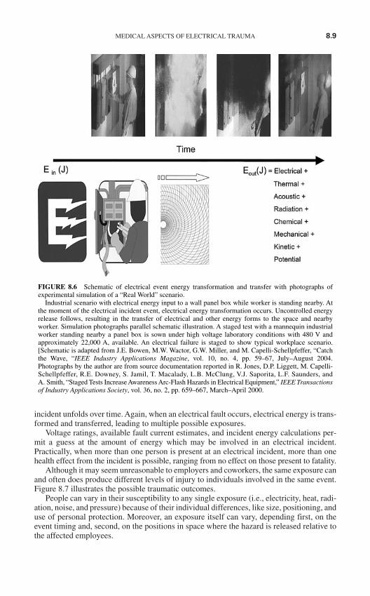
MEDICAL ASPECTS OF ELECTRICAL TRAUMA 8.9
incident unfolds over time. Again, when an electrical fault occurs, electrical energy is trans-formed and transferred, leading to multiple possible exposures.
Voltage ratings, available fault current estimates, and incident energy calculations per-mit a guess at the amount of energy which may be involved in an electrical incident.Practically, when more than one person is present at an electrical incident, more than onehealth effect from the incident is possible, ranging from no effect on those present to fatality.
Although it may seem unreasonable to employers and coworkers, the same exposure canand often does produce different levels of injury to individuals involved in the same event.Figure 8.7 illustrates the possible traumatic outcomes.
People can vary in their susceptibility to any single exposure (i.e., electricity, heat, radi-ation, noise, and pressure) because of their individual differences, like size, positioning, anduse of personal protection. Moreover, an exposure itself can vary, depending first, on theevent timing and, second, on the positions in space where the hazard is released relative tothe affected employees.
FIGURE 8.6 Schematic of electrical event energy transformation and transfer with photographs ofexperimental simulation of a “Real World” scenario.
Industrial scenario with electrical energy input to a wall panel box while worker is standing nearby. Atthe moment of the electrical incident event, electrical energy transformation occurs. Uncontrolled energyrelease follows, resulting in the transfer of electrical and other energy forms to the space and nearbyworker. Simulation photographs parallel schematic illustration. A staged test with a mannequin industrialworker standing nearby a panel box is sown under high voltage laboratory conditions with 480 V andapproximately 22,000 A, available. An electrical failure is staged to show typical workplace scenario.[Schematic is adapted from J.E. Bowen, M.W. Wactor, G.W. Miller, and M. Capelli-Schellpfeffer, “Catchthe Wave, “IEEE Industry Applications Magazine, vol. 10, no. 4, pp. 59–67, July–August 2004.Photographs by the author are from source documentation reported in R. Jones, D.P. Liggett, M. Capelli-Schellpfeffer, R.E. Downey, S. Jamil, T. Macalady, L.B. McClung, V.J. Saporita, L.F. Saunders, andA. Smith, “Staged Tests Increase Awareness Arc-Flash Hazards in Electrical Equipment,” IEEE Transactionsof Industry Applications Society, vol. 36, no. 2, pp. 659–667, March–April 2000.
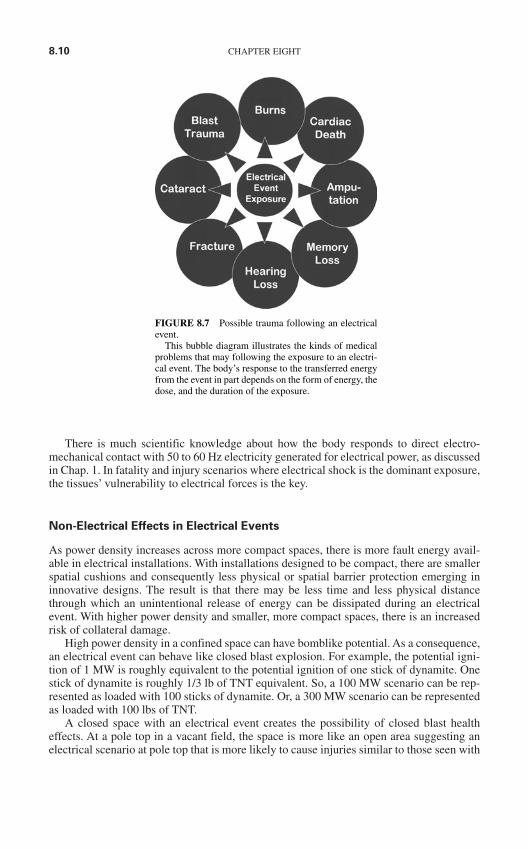
8.10 CHAPTER EIGHT
There is much scientific knowledge about how the body responds to direct electro-mechanical contact with 50 to 60 Hz electricity generated for electrical power, as discussedin Chap. 1. In fatality and injury scenarios where electrical shock is the dominant exposure,the tissues’ vulnerability to electrical forces is the key.
Non-Electrical Effects in Electrical Events
As power density increases across more compact spaces, there is more fault energy avail-able in electrical installations. With installations designed to be compact, there are smallerspatial cushions and consequently less physical or spatial barrier protection emerging ininnovative designs. The result is that there may be less time and less physical distancethrough which an unintentional release of energy can be dissipated during an electricalevent. With higher power density and smaller, more compact spaces, there is an increasedrisk of collateral damage.
High power density in a confined space can have bomblike potential. As a consequence,an electrical event can behave like closed blast explosion. For example, the potential igni-tion of 1 MW is roughly equivalent to the potential ignition of one stick of dynamite. Onestick of dynamite is roughly 1/3 lb of TNT equivalent. So, a 100 MW scenario can be rep-resented as loaded with 100 sticks of dynamite. Or, a 300 MW scenario can be representedas loaded with 100 lbs of TNT.
A closed space with an electrical event creates the possibility of closed blast healtheffects. At a pole top in a vacant field, the space is more like an open area suggesting anelectrical scenario at pole top that is more likely to cause injuries similar to those seen with
FIGURE 8.7 Possible trauma following an electricalevent.
This bubble diagram illustrates the kinds of medicalproblems that may following the exposure to an electri-cal event. The body’s response to the transferred energyfrom the event in part depends on the form of energy, thedose, and the duration of the exposure.
MEDICAL ASPECTS OF ELECTRICAL TRAUMA 8.11
a free blast. Blast trauma may include destruction from shrapnel, confined space air con-tamination, acoustic or pressure effects, and acceleration-deceleration brain effects.
In brief, when an electrical event involves more than a direct electromechanical currentexposure, the traumatic consequences can vary, as the bubble diagram suggests in Fig. 8.7.
Survivor Experience. As suggested in Table 8.6, an electrical event may unfold in frac-tions of a second. In electrical scenarios, a full second is a “long time,” suggesting a 60 cycleevent. Compare this to the investigation of an electrical incident which may take weeks tomonths. The litigation accompanying such an event typically takes years. Note that thelogistics of work do not permit a site to go “on hold” while these activities are underway.
Obviously, survivors experience an electrical event on a different time frame than theirworkplace. Practically, within a few work shifts, an electrical accident site may be operat-ing routinely. In contrast, the survivor experience may unfold from the moment of the elec-trical event through minutes of triage to years of rehabilitation.
Worker Reflexes. At the scene of an electrical event, survivors rely on their reflexes andsenses. As discussed in Chap. 11, to see, think, and then respond to a scenario demandinga choice requires at least 1.5 seconds. Physical responses to an unfolding electrical event ina shorter amount of time occur with reflexes, such as eye blinks in response to flash, orquick hand withdrawal from a hot surface.
Sometimes the injured survivor can “walk away” from the electrical event. However,this immediate postincident behavior may be deceptive, given the possible medical conse-quences of electrical trauma.
Instead of walking away, if a non-fatal electrical contact is made, a person may collapsewith the loss of regular heart function. As the heart’s pumping action becomes inefficient,the blood supply to the lungs and brain are severely limited, reducing the delivery of oxy-gen and glucose (the body’s fuel). When oxygen and glucose are not available because ofcirculation failure, a survivor can not breathe or remain upright or awake. This experiencemay be later recalled by a survivor as “near death” or “out of body.” At this time, success-ful cardiopulmonary resuscitation (CPR) is essential to rescue the affected individual.
TABLE 8.6 Timing of Workplace and Survivor ExperiencesAfter Electrical Events
Experience Timing
HazardEvent Fractions of millisecondsInvestigation Weeks to monthsLitigation Years
SurvivorWorker reflexes SecondsTriage & medical evacuation Event to Hour 1Stabilization & initial evaluation Hour 1 to Hour 8Medical & surgical intervention Hour 8 to Hour 24Hospitalization Day 2 to Day 9Discharge to outpatient services Day 10 to Day 30Rehabilitation Day 31 to Day 89Return to work planning Day 90 to Day 119Re-entry to employment Month 4 to Month 60Plateau in Recovery Beyond 5 Years
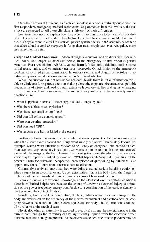
Once help arrives at the scene, an electrical incident survivor is routinely questioned. Asfirst responders, emergency medical technicians, or paramedics become involved, the sur-vivors are expected to tell these clinicians a “history” of their difficulties.
Survivors may need to explain how they were injured in order to get a medical evalua-tion. This may be difficult to do if the electrical accident has occurred quickly. For exam-ple, a 30 cycle event in a 60 Hz electrical power system occurs in 0.5 seconds. A scenariothat takes a half second to complete is faster than most people can even recognize, muchless remember in detail.
Triage and Medical Evacuation. Medical triage, evacuation, and treatment requires min-utes, hours, and longer, as discussed below. In the emergency or first response period,American Burn Association (ABA) Advanced Burn Life Support guidelines outline triage,initial resuscitation, and emergency transport protocols. On admission to the emergencymedical services, physical examination, laboratory studies, and diagnostic radiology eval-uation are prioritized depending on the patient’s clinical situation.
When the survivor can not remember accident details there is little information avail-able to clinicians for rigorous decision making about the exposure circumstances, possiblemechanisms of injury, and need to obtain extensive laboratory studies or diagnostic imaging.
If in coma or heavily medicated, the survivor may not be able to coherently answerquestions like:
What happened in terms of the energy like volts, amps, cycles? Was there a blast or an explosion? Was the space small or confined? Did you fall or lose consciousness? Were you wearing protection? Did you need CPR? Was anyone else hurt or killed at the scene?
Further confusion between a survivor who becomes a patient and clinicians may arisewhen the circumstances around the injury event simply can not be immediately known. Forexample, when a work situation is believed to be “safely de-energized” but leads to an elec-trical accident, engineers may investigate over weeks to months to establish the “root causes”and available energy to the fault. During that investigation time, the electrical incident sur-vivor may be repeatedly asked by clinicians, “What happened? Why didn’t you turn off thepower?” From the survivors’ perspective, each episode of questioning by clinicians is anopportunity for self-doubt about their accident recollection.
Commonly, survivors report that they were doing a manual task or handling equipmentwhen caught in an electrical event. Upper extremities, that is the body from the fingertipsto the shoulders, are involved in most trauma because of how work is done.
From a clinician’s viewpoint, knowledge of the electrical event’s voltage conditionsalone is of limited helpfulness because the extent of survivor’s electrical injury is a func-tion of the power frequency energy transfer due to a combination of the current density inthe tissue and the contact duration.
Similarly, from a medical perspective, the heat, radiation, and pressure damage to thebody are predicated on the efficiency of the electro-mechanical and electro-chemical cou-pling between the hazardous source, event space, and the body. This information is not usu-ally available to the medical team.
Physically, when an extremity is exposed to electrical current, the skeletal muscle in thecurrent path through the extremity can be significantly injured from the electrical effect,extreme heat, and damage to proteins. At the electrical accident site, first responders may see
8.12 CHAPTER EIGHT
MEDICAL ASPECTS OF ELECTRICAL TRAUMA 8.13
minimal skin wounds, or they might notice profound charring and vaporization of tissue.Even in the absence of impressive wounds, the survivor’s risk of amputation can be high.
After a severe electrical contact injury, a survivor’s injured muscles can swell massively,resulting in a situation referred to as “compartment syndrome.” In a compartment syndrome,the blood supply to local muscle is literally squeezed by swelling. With this swelling, oxygensupply to the muscle can be “choked.” Without oxygen from the blood supply, muscle tissuedies. If muscle tissue dies, proteins are lost as waste and filtered by the kidneys. These proteinscan block the kidneys and result in kidney or renal failure.
Other significant features of severe electrical exposure include disturbances in the sur-vivor’s heart electrical pattern, called refractory cardiac arrhythmias. Further serious prob-lems may include:
Neck and back fractures from the electrical current exposure, falls, or blast. Disruption in the blood serum’s balance of sodium, potassium, and chloride. Transient lifeless signs, including a situation referred to as keraunoparalysis. Shock lung, perforated ear drums, and ruptured gastrointestinal organs subsequent to
blast trauma.
In high voltage electrical incidents, current passing through a limb across oppositesides of a joint can set up large skin or “trans-dermal” potentials, resulting in burns called“kissing” wounds. The most frequent sites of this trauma include:
At the armpit or axilla, with injury between the limb and skin of the chest. At the leg by the space in back of the knee, where the skin of the upper and lower leg can
meet when the survivor is caught in a crouched position.
Other skin burns may result in the following ways:
With ohmic or Joule heating at the electrical contact points between the survivor and theelectrical hazard.
From the ignition of clothing burning in place against the survivor’s skin. At unprotected skin exposed in the extremes of heat generated by electrical arcing.
Stabilization and Initial Evaluation
Severely electrically injured victims are difficult to resuscitate and the early phase of med-ical management can be very complex. Survivors are best served by admission to a burntrauma center where staffing is experienced in the management of patients with massiveloss of tissue from electrical current damage and burns.
From the survivor’s perspective, after a severely traumatic accident, a breathing tube,intravenous fluids, and massive pain control medicines obliterate awareness of all that hap-pens in the early treatment period.
Because nerves are very sensitive to electrical forces, even minor electrical exposuresmay cause temporary nerve dysfunction in the affected arms or upper extremities. Pain maydominate, or nerve symptoms referred to with the medical terms anesthesia (no feeling),parathesia (some feelings), or dysesthesia (prickly, pin-prick, or knife-like feelings) mayoccur. In this situation the survivor may experience loss of feeling or “funny” feelings inthe areas affected by electrical shock. These problems are referred to as “stunning” andhamper how effective hand grip is in terms of strength, endurance, and reliability. Stunningusually completely resolves within hours or days.
Although less common, electrical contacts may also lead to a nerve problem called tem-porary autonomic nervous system dysfunction, which may show up in the patient as specif-ically reflex sympathetic dystrophy (RSD), and hypertension or high blood pressure.
Less quickly resolved for a survivor are the classic complaints of burning pain and exquisitesensitivity which may develop within hours after an electrical injury. Swelling (called edema)and excessive sweats may then manifest during the next three to six months. This maybe fol-lowed in six to twelve months with loss of muscle mass, nails, and hair. Osteoporosis maydevelop in the limb. To evaluate this problem, clinicians conduct diagnostic nerve tests and treatwith injections of medication near the nerves to produce a “nerve blockade.”
Medical and Surgical Intervention
For a survivor with a severe electrical exposure, more intensive medical and surgical care areneeded. The diagnostic evaluation of muscle and nerve injury unfolds while the patient’s clin-ical condition is being stabilized. A goal is to distinguish central nervous system damage fromperipheral nerve injury. Key steps are summarized in Table 8.7, adapted from Danielson et al.18
When an injury appears less severe, diagnostic testing in a hospital may still be neces-sary because the health changes resulting from electrical exposure may not be obvious forhours. An employee who “walks away” from an electrical event may not want to draw moreattention to their accident by seeking or attending a medical evaluation. Yet because thebody damage may not be “detectable” by the eye, an exposed employee should always beencouraged to have a medical check up.
Hospitalization. For the survivor who may have been involved in a serious occupationalelectrical event, during days or weeks of hospitalization the uncertainty in answering a clin-icians’ questions (eg., “What happened?” “Why did this happen?” “How were you hurt?”)can hamper their medical treatment and amplify their distress at their injury.
Moreover, an experienced, knowledgeable, and competent employee can be made tofeel ignorant, uninformative, manipulative, or uncooperative. After surviving a workplaceelectrical accident, the employee is essentially moved from the occupational environment,where he may be considered “a good worker” or an “expert at his job,” to the hospital envi-ronment and the medical care delivery system, where the survivor may only be known byreference to a medical record number, a date of admission, and a treating physician’s name.Concurrently, for family or coworkers who have not been hurt, the hospitalization experi-ence can be alienating and frightening.
Discharge to Outpatient Services. As a consequence of an electrical event, the healtheffects can range from the absence of any external physical signs to severe multiple trauma.Even without a visible physical injury like burns or electrical contact wounds, survivorsmay report medical complaints. These complaints may seem unrelated to the electricalevent sometimes because they show up hours, days, or weeks after the occurrence, orbecause they seem more or less severe than the event itself.
This situation can go from bad to worse when the facts of the injury scenario do emerge,and a survivor learns that he has experienced a near fatal situation. Hearing comments like“You are lucky to be alive!” can disintegrate the worker’s belief in their professional com-petence. Employees who work around electricity don’t survive on luck. Worse is the factthat having a near death accident doesn’t “feel” lucky to most.
In particular, electricians especially hold to an occupational identity and set off beliefsthat suggest workplace policies, procedures, planning, and personal protection can providefor safe occupational activity. When a worker’s identity or beliefs are threatened, anxiety,adjustment reactions, or more serious psychiatric issues should be expected. If the facts of
8.14 CHAPTER EIGHT
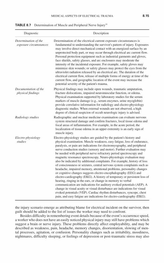
the injury scenario emerge as attributing blame for electrical incident on the survivor, thenguilt should be added to the list of issues the worker may need to confront.
Besides difficulty in remembering event details because of the event’s occurrence speed,a worker who does not have an easily noticed physical injury may still have problems whichsuggest a brain or nerve injury. These problems directly affect employability, and may bedescribed as weakness, pain, headache, memory changes, disorientation, slowing of men-tal processes, agitation, or confusion. Personality changes such as irritability, moodiness,nightmares, difficulty sleeping, or feelings of depression or post-traumatic stress may also
MEDICAL ASPECTS OF ELECTRICAL TRAUMA 8.15
TABLE 8.7 Determination of Muscle and Peripheral Nerve Injury18
Diagnostic Description
Determination of the Determination of the electrical current exposure circumstances is exposure circumstances fundamental to understanding the survivor's pattern of injury. Exposures
may involve direct mechanical contact with an energized surface by anunprotected body part, or may occur through electrical arc current flow.Personal protection equipment such as industrial garments and gloves,face shields, safety glasses, and arc enclosures may moderate theintensity of the incidental exposure. For example, safety gloves mayminimize skin wounds; or safety glasses may protect the eyes from theultraviolet radiation released by an electrical arc. The duration of theelectrical current flow, release of multiple forms of energy at time of thecurrent flow, and geographic location of the event may increase thepotential severity of the patient's trauma.
Documentation of the Physical findings may include open wounds, traumatic amputation,physical findings fracture dislocations, impaired neuromuscular function, or edema.
Physical examination supported by laboratory studies for the serummarkers of muscle damage (e.g., serum enzymes, urine myoglobin)provide correlative information for radiology and electro-physiologydiagnostic studies. When external wounds are not observed, a highdegree of clinical suspicion of occult neurologic injury is advised.
Radiology studies Radiographic and nuclear medicine examination can evaluate nervous system structural damage and confirm fractures, local tissue edema andfocal areas of inflammation. For example, in the acute period, thelocalization of tissue edema in an upper extremity is an early sign ofmuscle injury.
Electro-physiology Electro-physiology studies are guided by the patient's history and studies physical examination. Muscle weakness, easy fatigue, loss of endurance,
paralysis, or pain are indications for electromyography, and peripheralnerve conduction studies (sensory and motor). Further evaluation maybe needed with peripheral nerve refractory period spectroscopy andmagnetic resonance spectroscopy. Neuro-physiologic evaluation mayalso be indicated by additional complaints. For example, history of lossof consciousness or seizures, central nervous system complaints such asheadache, impaired memory, attentional problems, personality changesor cognitive changes suggests electro-encephalography (EEG) andelectro-cardiography (EKG). A history of temporary or persistent loss ofhearing, ringing in the ears, or change in memory to verbalcommunication are indications for auditory evoked potentials (AEP). Achange in visual acuity or visual disturbance are indications for visualevoked potentials (VEP). Cardiac rhythm disturbances, syncope, chestpain, and easy fatigue are indications for electro-cardiography (EKG).
occur. These changes can interfere with personal and workplace relationships, straining aworker’s support network.
REHABILITATION FOCUS AND RETURN TO WORK PLANNING
Rehabilitation and return to work (RTW) may take weeks to months. With massive trauma,years may be necessary to return a survivor to active employment. For example, a seriouslyinjured high-voltage electrical shock survivor can be reemployed, however the rehabilitationperiod may extend months beyond the time of the patient’s acute hospitalization and surgicalmanagement.
Successful rehabilitation often does not lead to the return of the patients to their prein-jury job. The disability for electrical incident survivors is disproportionate to the incidenceof this preventable condition. This means, for relatively few injuries, there is a relativelyhigh frequency of permanent disability. With the typical youth of those injured in electricalaccidents and the loss of potential productivity in economic terms, the health effects of elec-trical incidents carry significant costs for victims, their families, and their employers.
Re-Entry to Employment Settings
When workers have difficulty in the use of their limbs after an electrical incident, theirsecurity in completing tasks (like exerting a forceful grip, climbing a ladder, using to handsto lift a load, assisting a coworker in a hazardous activity) may be unacceptably compro-mised. This difficulty can drastically reduce employment options. Workers may wish toreturn to their job, but face resistance in this step from their family because of their con-cerns for reinjury. When the electrical incident is felt to be the victim’s “fault,” coworkersmay harbor undisclosed resentments, acting as a roadblock to reentry to employment.
Plateau in Recovery
The complexities of electrical injury rehabilitation are often under-appreciated by the med-ical community. As a general guide, three elements are essential to successful recovery fol-lowing an electrical incident: team, time, and talk. The involvement of an experiencedoccupational rehabilitation team is needed to avoid the catastrophe of repeated failure toreturn to work, depression, and loss of self-respect that may evolve when injured workersfear for their livelihood. Time is necessary for the survivor to go through the healing stagesfollowing repeated surgeries, possible amputation, and long hospitalizations. Talk or excel-lent communication is critical to maintaining the employee’s relationships with family,friends, coworkers, and caregivers.
Research suggests electrical trauma survival is associated with significant functionalimpairment. In a landmark retrospective study of employees of a national electrical energycompany, Gourbiere and colleagues reviewed the electrical trauma survival experience dur-ing 1970–1989 for a workforce between 100,000 and 120,000 during this period. Electricalburns affected 2,080 workers. Of these, 515 patients or 25 percent were noted to havepostinjury problems, including:
63 percent burn related, with amputations in 5 percent 18 percent neuropsychiatric
8.16 CHAPTER EIGHT
12 percent sensory 5 percent orthopedic 1 percent cardiovascular
Sense organ problems were also noted, including:
Vision related changes due to conjunctivitis, keratitis, and cataracts. Auditory sequella, with conductive or sensorineural hearing loss, tinnitus, and vertigo. Anosmia, or the loss of sense of smell.
In 59 of the 515 patients, disability was considered serious, with impairment rating 31to 100 percent.19
Return to work success of electrical trauma patients is variable. While some electricaltrauma patients are able to return to their preinjury activities without functional impairment,others are not. Postinjury job loss can be seen with the survivors who are “owner operators” oftheir business, as well as with employees from larger organizations. While their postinjurymedical care may not interfere with their company’s core business, after accident a survivor’sjob may not exist due to competition from other vendors, contract completion, restaffing, orworkforce reductions.
In one study, all patients had peripheral electrical contacts, with no evidence on history orexamination of direct mechanical electrical contact with the head. Forty-four patients wereinjured on the job and nine were injured during non-vocational activities. At the time of follow-up study interviews, 30 (56.6 percent) patients were working again, 18 (44.0 percent) patientswere unemployed or retired, 1 patient was deceased, and 4 patients could not be contacted.20
If the survivors wish to return to work, and their preinjury job is not available, the clin-ician can be influential in assisting placement into new work. To limit the potentiallydestructive effect of financial uncertainty on the survivor and their personal or family situ-ation, when a clinician is advising on placement in new work, a vocational evaluation is rec-ommended as soon as possible to establish the local employment area’s market for thesurvivor’s skills set, occupational abilities, and training.
For example, driving is a common requirement in service jobs where travel is necessary todeliver tasks to client sites, like construction locations, factories, or customer businesses. UnderU.S. Department of Transportation (DOT) rules, a person can not be medically certified for acommercial driver’s license if there is a recent history of loss of consciousness, vision less than40/40 in each eye and both eyes, certain cardiac conditions, and certain medications.21 Whereamputations are present, demonstration must be made of the performance in driving a vehiclethat may fall under DOT rules. When the patient can not drive a DOT regulated vehicle,designed work support is necessary to allow access to job sites and equipment.
Another aspect of industrial work is the need for bimanual secure grip. To climb a lad-der, lift a load, or handle a heavy tool, secure, forceful bimanual grip which can be reliablyand repeatedly used is an essential function of the job. When finger or hand amputation isa consequence of electrical trauma, supported work to offset the limitation of securebimanual grip is needed.
At a certain point after an electrical trauma, survivors reach a plateau in their recovery.It can take years longer than the time to plateau after recovery from a serious illness likepneumonia or a heart attack. With consideration for numerous surgeries, retraining for employ-ment, and mental health care, plateaus are assessed on an individual basis. Nevertheless, acommon characteristic is that the survivors rarely go “back” to the life they had before theirincident. A survivor typically goes “forward” by living differently. The differences can besmall, as with an attitude change, or dramatic, as with a job change. The bottom line for thesurvivor is that, after electrical trauma life may never be the same.
MEDICAL ASPECTS OF ELECTRICAL TRAUMA 8.17
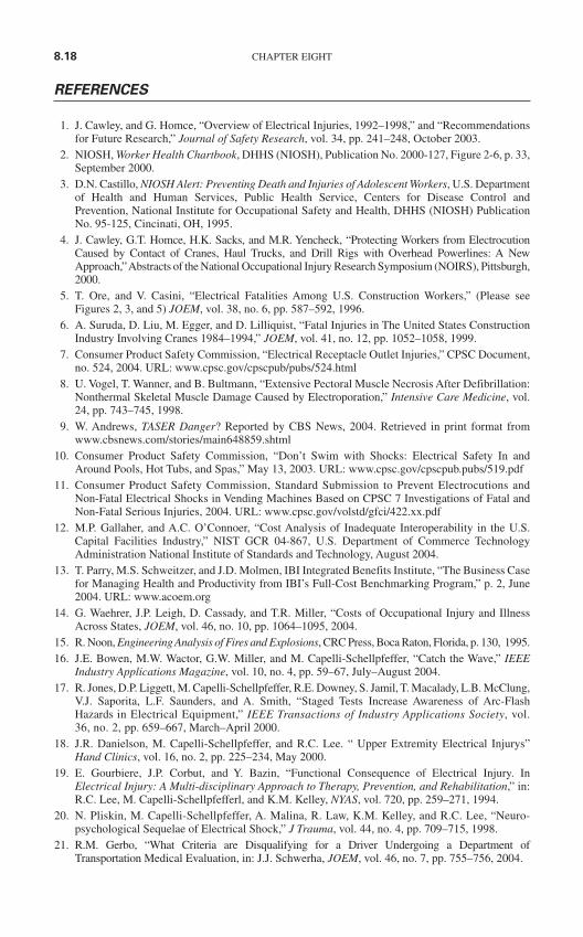
REFERENCES
1. J. Cawley, and G. Homce, “Overview of Electrical Injuries, 1992–1998,” and “Recommendationsfor Future Research,” Journal of Safety Research, vol. 34, pp. 241–248, October 2003.
2. NIOSH, Worker Health Chartbook, DHHS (NIOSH), Publication No. 2000-127, Figure 2-6, p. 33,September 2000.
3. D.N. Castillo, NIOSH Alert: Preventing Death and Injuries of Adolescent Workers, U.S. Departmentof Health and Human Services, Public Health Service, Centers for Disease Control andPrevention, National Institute for Occupational Safety and Health, DHHS (NIOSH) PublicationNo. 95-125, Cincinati, OH, 1995.
4. J. Cawley, G.T. Homce, H.K. Sacks, and M.R. Yencheck, “Protecting Workers from ElectrocutionCaused by Contact of Cranes, Haul Trucks, and Drill Rigs with Overhead Powerlines: A NewApproach,” Abstracts of the National Occupational Injury Research Symposium (NOIRS), Pittsburgh,2000.
5. T. Ore, and V. Casini, “Electrical Fatalities Among U.S. Construction Workers,” (Please seeFigures 2, 3, and 5) JOEM, vol. 38, no. 6, pp. 587–592, 1996.
6. A. Suruda, D. Liu, M. Egger, and D. Lilliquist, “Fatal Injuries in The United States ConstructionIndustry Involving Cranes 1984–1994,” JOEM, vol. 41, no. 12, pp. 1052–1058, 1999.
7. Consumer Product Safety Commission, “Electrical Receptacle Outlet Injuries,” CPSC Document,no. 524, 2004. URL: www.cpsc.gov/cpscpub/pubs/524.html
8. U. Vogel, T. Wanner, and B. Bultmann, “Extensive Pectoral Muscle Necrosis After Defibrillation:Nonthermal Skeletal Muscle Damage Caused by Electroporation,” Intensive Care Medicine, vol.24, pp. 743–745, 1998.
9. W. Andrews, TASER Danger? Reported by CBS News, 2004. Retrieved in print format fromwww.cbsnews.com/stories/main648859.shtml
10. Consumer Product Safety Commission, “Don’t Swim with Shocks: Electrical Safety In andAround Pools, Hot Tubs, and Spas,” May 13, 2003. URL: www.cpsc.gov/cpscpub.pubs/519.pdf
11. Consumer Product Safety Commission, Standard Submission to Prevent Electrocutions andNon-Fatal Electrical Shocks in Vending Machines Based on CPSC 7 Investigations of Fatal andNon-Fatal Serious Injuries, 2004. URL: www.cpsc.gov/volstd/gfci/422.xx.pdf
12. M.P. Gallaher, and A.C. O’Connoer, “Cost Analysis of Inadequate Interoperability in the U.S.Capital Facilities Industry,” NIST GCR 04-867, U.S. Department of Commerce TechnologyAdministration National Institute of Standards and Technology, August 2004.
13. T. Parry, M.S. Schweitzer, and J.D. Molmen, IBI Integrated Benefits Institute, “The Business Casefor Managing Health and Productivity from IBI’s Full-Cost Benchmarking Program,” p. 2, June2004. URL: www.acoem.org
14. G. Waehrer, J.P. Leigh, D. Cassady, and T.R. Miller, “Costs of Occupational Injury and IllnessAcross States, JOEM, vol. 46, no. 10, pp. 1064–1095, 2004.
15. R. Noon, Engineering Analysis of Fires and Explosions, CRC Press, Boca Raton, Florida, p. 130, 1995.16. J.E. Bowen, M.W. Wactor, G.W. Miller, and M. Capelli-Schellpfeffer, “Catch the Wave,” IEEE
Industry Applications Magazine, vol. 10, no. 4, pp. 59–67, July–August 2004.17. R. Jones, D.P. Liggett, M. Capelli-Schellpfeffer, R.E. Downey, S. Jamil, T. Macalady, L.B. McClung,
V.J. Saporita, L.F. Saunders, and A. Smith, “Staged Tests Increase Awareness of Arc-FlashHazards in Electrical Equipment,” IEEE Transactions of Industry Applications Society, vol.36, no. 2, pp. 659–667, March–April 2000.
18. J.R. Danielson, M. Capelli-Schellpfeffer, and R.C. Lee. “ Upper Extremity Electrical Injurys”Hand Clinics, vol. 16, no. 2, pp. 225–234, May 2000.
19. E. Gourbiere, J.P. Corbut, and Y. Bazin, “Functional Consequence of Electrical Injury. InElectrical Injury: A Multi-disciplinary Approach to Therapy, Prevention, and Rehabilitation,” in:R.C. Lee, M. Capelli-Schellpfefferl, and K.M. Kelley, NYAS, vol. 720, pp. 259–271, 1994.
20. N. Pliskin, M. Capelli-Schellpfeffer, A. Malina, R. Law, K.M. Kelley, and R.C. Lee, “Neuro-psychological Sequelae of Electrical Shock,” J Trauma, vol. 44, no. 4, pp. 709–715, 1998.
21. R.M. Gerbo, “What Criteria are Disqualifying for a Driver Undergoing a Department ofTransportation Medical Evaluation, in: J.J. Schwerha, JOEM, vol. 46, no. 7, pp. 755–756, 2004.
8.18 CHAPTER EIGHT
9.1
CHAPTER 9LOW-VOLTAGE
SAFETY SYNOPSIS
INTRODUCTION
Each year 120-V circuits cause more deaths and injuries than circuits of all other voltagelevels combined. Such low-voltage circuits are extremely hazardous for two reasons. First,low-voltage circuits are the most common. Because they are the final distribution voltage,240-V and 120-V circuits are used throughout residential, commercial, industrial, and util-ity systems.
The second reason for the extreme danger of low-voltage circuits is user apathy.Comments such as “It can’t hurt you, it’s only 120 volts,” are heard all too often. Referenceto Table 9.1 shows that 120-V circuits can produce currents through the human body thatcan easily reach fibrillation levels. Consider a perspiring worker using a metal electric drillwith one foot immersed in water. Table 9.1 clearly shows that under such conditions, aworker can be subjected to a lethal shock. Furthermore, if sustained for a sufficient period,120-V contact can create severe burns.
A 480-V circuit is more than four times as lethal as a 120-V circuit. A 480-V circuit hassufficient energy to sustain arcing faults and to create severe blast conditions. This chaptersummarizes some of the safety-related concerns that apply to low-voltage circuits—that is,circuits of 1000 V AC and less and 250 V DC and less. Generally, workers should treat low-voltage circuits with the same degree of respect afforded medium- and high-voltage cir-cuits. Refer to Chaps. 2 and 3 for detailed information. Note that some of the safety-relatedinformation covered in this chapter also applies to medium- and high-voltage systems.Where necessary, the information is repeated in Chap. 10.
Electrical safety requirements when working on or near electronic circuits can be a prob-lem. For example, the dictates of electrical safety would seem to require that circuit parts andworkers be insulated from one another. In some electronic circuits, however, the preventionof static electricity damage requires that the worker be grounded. Also, many workers developa sense of false security believing that 12,000 V in an electronic circuit is somehow less haz-ardous than 12,000 V in a power system. This chapter will also present and explain the elec-trical safety procedures to be employed when working on or near electronic circuits.
LOW-VOLTAGE EQUIPMENT
Hand tools and extension cords are the most commonly used pieces of low-voltage equip-ment. Each of these items is responsible for hundreds of injuries and deaths each year.
Copyright © 2006 by The McGraw-Hill Companies, Inc. Click here for terms of use.
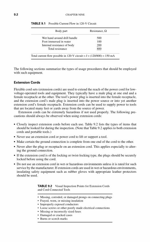
The following sections summarize the types of usage procedures that should be employedwith such equipment.
Extension Cords
Flexible cord sets (extension cords) are used to extend the reach of the power cord for low-voltage-operated tools and equipment. They typically have a male plug at one end and afemale receptacle at the other. The tool’s power plug is inserted into the female receptacle,and the extension cord’s male plug is inserted into the power source or into yet anotherextension cord’s female receptacle. Extension cords can be used to supply power to toolsthat are located many feet or yards away from the source of power.
Extension cords can be extremely hazardous if not used properly. The following pre-cautions should always be observed when using extension cords:
Closely inspect extension cords before each use. Table 9.2 lists the types of items thatshould be looked for during the inspection. (Note that Table 9.2 applies to both extensioncords and portable tools.)
Never use an extension cord or power cord to lift or support a tool. Make certain the ground connection is complete from one end of the cord to the other. Never alter the plug or receptacle on an extension cord. This applies especially to alter-
ing the ground connection. If the extension cord is of the locking or twist-locking type, the plugs should be securely
locked before using the cord. Do not use an extension cord in wet or hazardous environments unless it is rated for such
service by the manufacturer. If extension cords are used in wet or hazardous environments,insulating safety equipment such as rubber gloves with appropriate leather protectorsshould be used.
9.2 CHAPTER NINE
TABLE 9.2 Visual Inspection Points for Extension Cordsand Cord-Connected Tools
• Missing, corroded, or damaged prongs on connecting plugs• Frayed, worn, or missing insulation• Improperly exposed conductors• Loose screws or other poorly made electrical connections• Missing or incorrectly sized fuses• Damaged or cracked cases• Burns or scorch marks
TABLE 9.1 Possible Current Flow in 120-V Circuit
Body part Resistance, Ω
Wet hand around drill handle 500Foot immersed in water 100Internal resistance of body 200
Total resistance 800
Total current flow possible in 120-V circuit = I = (120/800) = 150 mA
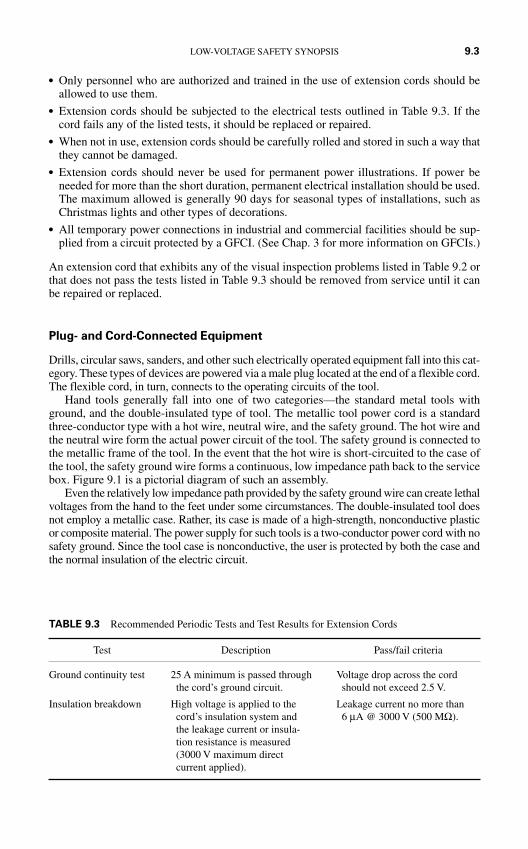
Only personnel who are authorized and trained in the use of extension cords should beallowed to use them.
Extension cords should be subjected to the electrical tests outlined in Table 9.3. If thecord fails any of the listed tests, it should be replaced or repaired.
When not in use, extension cords should be carefully rolled and stored in such a way thatthey cannot be damaged.
Extension cords should never be used for permanent power illustrations. If power beneeded for more than the short duration, permanent electrical installation should be used.The maximum allowed is generally 90 days for seasonal types of installations, such asChristmas lights and other types of decorations.
All temporary power connections in industrial and commercial facilities should be sup-plied from a circuit protected by a GFCI. (See Chap. 3 for more information on GFCIs.)
An extension cord that exhibits any of the visual inspection problems listed in Table 9.2 orthat does not pass the tests listed in Table 9.3 should be removed from service until it canbe repaired or replaced.
Plug- and Cord-Connected Equipment
Drills, circular saws, sanders, and other such electrically operated equipment fall into this cat-egory. These types of devices are powered via a male plug located at the end of a flexible cord.The flexible cord, in turn, connects to the operating circuits of the tool.
Hand tools generally fall into one of two categories—the standard metal tools withground, and the double-insulated type of tool. The metallic tool power cord is a standardthree-conductor type with a hot wire, neutral wire, and the safety ground. The hot wire andthe neutral wire form the actual power circuit of the tool. The safety ground is connected tothe metallic frame of the tool. In the event that the hot wire is short-circuited to the case ofthe tool, the safety ground wire forms a continuous, low impedance path back to the servicebox. Figure 9.1 is a pictorial diagram of such an assembly.
Even the relatively low impedance path provided by the safety ground wire can create lethalvoltages from the hand to the feet under some circumstances. The double-insulated tool doesnot employ a metallic case. Rather, its case is made of a high-strength, nonconductive plasticor composite material. The power supply for such tools is a two-conductor power cord with nosafety ground. Since the tool case is nonconductive, the user is protected by both the case andthe normal insulation of the electric circuit.
LOW-VOLTAGE SAFETY SYNOPSIS 9.3
TABLE 9.3 Recommended Periodic Tests and Test Results for Extension Cords
Test Description Pass/fail criteria
Ground continuity test 25 A minimum is passed through Voltage drop across the cordthe cord’s ground circuit. should not exceed 2.5 V.
Insulation breakdown High voltage is applied to the Leakage current no more than cord’s insulation system and 6 µA @ 3000 V (500 MΩ).the leakage current or insula-tion resistance is measured (3000 V maximum direct current applied).
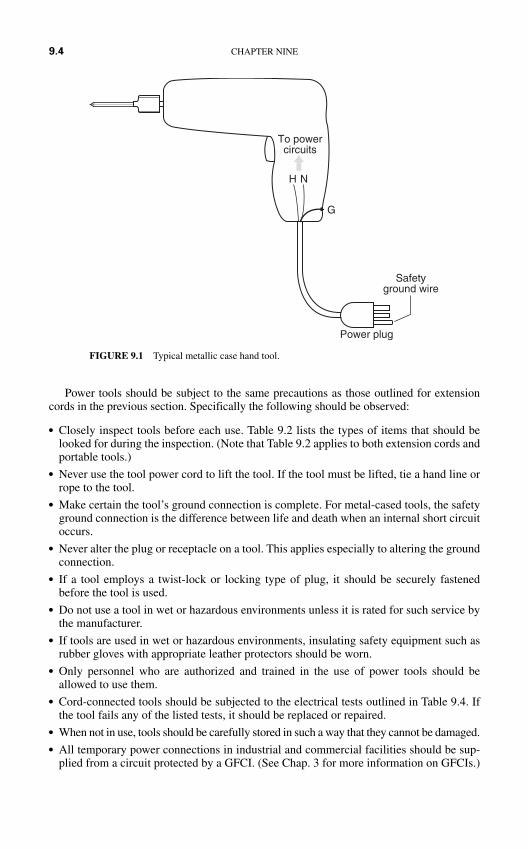
Power tools should be subject to the same precautions as those outlined for extensioncords in the previous section. Specifically the following should be observed:
Closely inspect tools before each use. Table 9.2 lists the types of items that should belooked for during the inspection. (Note that Table 9.2 applies to both extension cords andportable tools.)
Never use the tool power cord to lift the tool. If the tool must be lifted, tie a hand line orrope to the tool.
Make certain the tool’s ground connection is complete. For metal-cased tools, the safetyground connection is the difference between life and death when an internal short circuitoccurs.
Never alter the plug or receptacle on a tool. This applies especially to altering the groundconnection.
If a tool employs a twist-lock or locking type of plug, it should be securely fastenedbefore the tool is used.
Do not use a tool in wet or hazardous environments unless it is rated for such service bythe manufacturer.
If tools are used in wet or hazardous environments, insulating safety equipment such asrubber gloves with appropriate leather protectors should be worn.
Only personnel who are authorized and trained in the use of power tools should beallowed to use them.
Cord-connected tools should be subjected to the electrical tests outlined in Table 9.4. Ifthe tool fails any of the listed tests, it should be replaced or repaired.
When not in use, tools should be carefully stored in such a way that they cannot be damaged. All temporary power connections in industrial and commercial facilities should be sup-
plied from a circuit protected by a GFCI. (See Chap. 3 for more information on GFCIs.)
9.4 CHAPTER NINE
To powercircuits
H N
Power plug
Safetyground wire
G
FIGURE 9.1 Typical metallic case hand tool.
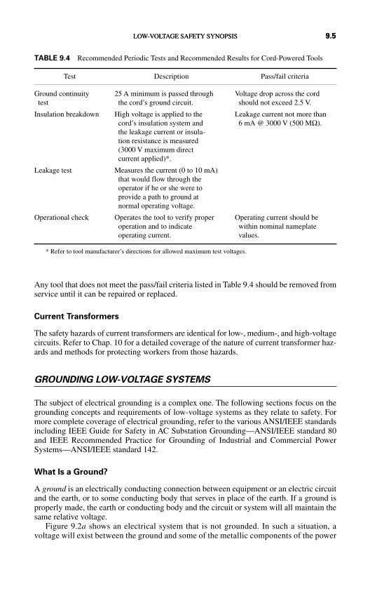
Any tool that does not meet the pass/fail criteria listed in Table 9.4 should be removed fromservice until it can be repaired or replaced.
Current Transformers
The safety hazards of current transformers are identical for low-, medium-, and high-voltagecircuits. Refer to Chap. 10 for a detailed coverage of the nature of current transformer haz-ards and methods for protecting workers from those hazards.
GROUNDING LOW-VOLTAGE SYSTEMS
The subject of electrical grounding is a complex one. The following sections focus on thegrounding concepts and requirements of low-voltage systems as they relate to safety. Formore complete coverage of electrical grounding, refer to the various ANSI/IEEE standardsincluding IEEE Guide for Safety in AC Substation Grounding—ANSI/IEEE standard 80and IEEE Recommended Practice for Grounding of Industrial and Commercial PowerSystems—ANSI/IEEE standard 142.
What Is a Ground?
A ground is an electrically conducting connection between equipment or an electric circuitand the earth, or to some conducting body that serves in place of the earth. If a ground isproperly made, the earth or conducting body and the circuit or system will all maintain thesame relative voltage.
Figure 9.2a shows an electrical system that is not grounded. In such a situation, avoltage will exist between the ground and some of the metallic components of the power
LOW-VOLTAGE SAFETY SYNOPSIS 9.5
TABLE 9.4 Recommended Periodic Tests and Recommended Results for Cord-Powered Tools
Test Description Pass/fail criteria
Ground continuity 25 A minimum is passed through Voltage drop across the cordtest the cord’s ground circuit. should not exceed 2.5 V.
Insulation breakdown High voltage is applied to the Leakage current not more thancord’s insulation system and 6 mA @ 3000 V (500 MΩ).the leakage current or insula-tion resistance is measured (3000 V maximum direct current applied)*.
Leakage test Measures the current (0 to 10 mA)that would flow through the operator if he or she were to provide a path to ground at normal operating voltage.
Operational check Operates the tool to verify proper Operating current should beoperation and to indicate within nominal nameplate operating current. values.
* Refer to tool manufacturer’s directions for allowed maximum test voltages.
LOW-VOLTAGE SAFETY SYNOPSIS 9.5
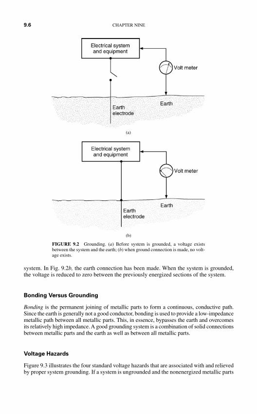
system. In Fig. 9.2b, the earth connection has been made. When the system is grounded,the voltage is reduced to zero between the previously energized sections of the system.
Bonding Versus Grounding
Bonding is the permanent joining of metallic parts to form a continuous, conductive path.Since the earth is generally not a good conductor, bonding is used to provide a low-impedancemetallic path between all metallic parts. This, in essence, bypasses the earth and overcomesits relatively high impedance. A good grounding system is a combination of solid connectionsbetween metallic parts and the earth as well as between all metallic parts.
Voltage Hazards
Figure 9.3 illustrates the four standard voltage hazards that are associated with and relievedby proper system grounding. If a system is ungrounded and the nonenergized metallic parts
9.6 CHAPTER NINE
(b)
FIGURE 9.2 Grounding. (a) Before system is grounded, a voltage existsbetween the system and the earth; (b) when ground connection is made, no volt-age exists.
(a)
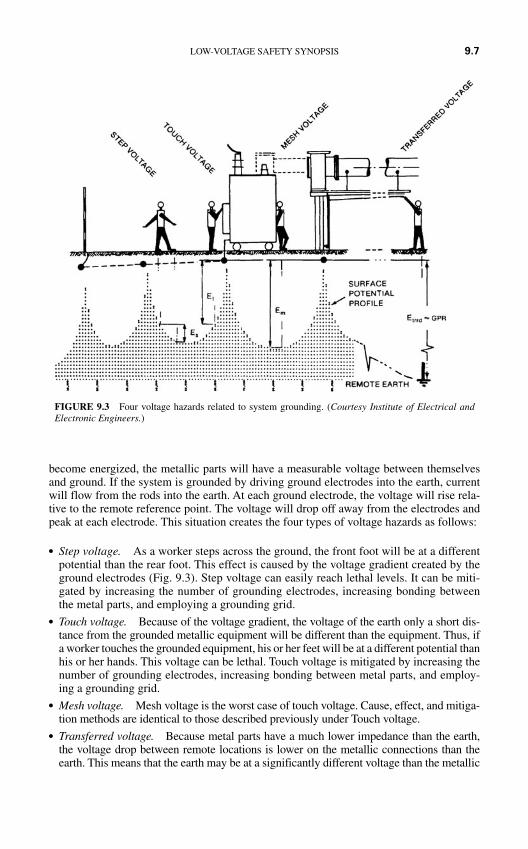
become energized, the metallic parts will have a measurable voltage between themselvesand ground. If the system is grounded by driving ground electrodes into the earth, currentwill flow from the rods into the earth. At each ground electrode, the voltage will rise rela-tive to the remote reference point. The voltage will drop off away from the electrodes andpeak at each electrode. This situation creates the four types of voltage hazards as follows:
Step voltage. As a worker steps across the ground, the front foot will be at a differentpotential than the rear foot. This effect is caused by the voltage gradient created by theground electrodes (Fig. 9.3). Step voltage can easily reach lethal levels. It can be miti-gated by increasing the number of grounding electrodes, increasing bonding betweenthe metal parts, and employing a grounding grid.
Touch voltage. Because of the voltage gradient, the voltage of the earth only a short dis-tance from the grounded metallic equipment will be different than the equipment. Thus, ifa worker touches the grounded equipment, his or her feet will be at a different potential thanhis or her hands. This voltage can be lethal. Touch voltage is mitigated by increasing thenumber of grounding electrodes, increasing bonding between metal parts, and employ-ing a grounding grid.
Mesh voltage. Mesh voltage is the worst case of touch voltage. Cause, effect, and mitiga-tion methods are identical to those described previously under Touch voltage.
Transferred voltage. Because metal parts have a much lower impedance than the earth,the voltage drop between remote locations is lower on the metallic connections than theearth. This means that the earth may be at a significantly different voltage than the metallic
FIGURE 9.3 Four voltage hazards related to system grounding. (Courtesy Institute of Electrical andElectronic Engineers.)
LOW-VOLTAGE SAFETY SYNOPSIS 9.7
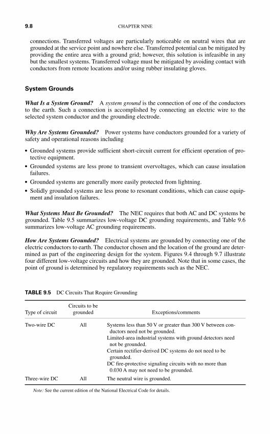
connections. Transferred voltages are particularly noticeable on neutral wires that aregrounded at the service point and nowhere else. Transferred potential can be mitigated byproviding the entire area with a ground grid; however, this solution is infeasible in anybut the smallest systems. Transferred voltage must be mitigated by avoiding contact withconductors from remote locations and/or using rubber insulating gloves.
System Grounds
What Is a System Ground? A system ground is the connection of one of the conductorsto the earth. Such a connection is accomplished by connecting an electric wire to theselected system conductor and the grounding electrode.
Why Are Systems Grounded? Power systems have conductors grounded for a variety ofsafety and operational reasons including
Grounded systems provide sufficient short-circuit current for efficient operation of pro-tective equipment.
Grounded systems are less prone to transient overvoltages, which can cause insulationfailures.
Grounded systems are generally more easily protected from lightning. Solidly grounded systems are less prone to resonant conditions, which can cause equip-
ment and insulation failures.
What Systems Must Be Grounded? The NEC requires that both AC and DC systems begrounded. Table 9.5 summarizes low-voltage DC grounding requirements, and Table 9.6summarizes low-voltage AC grounding requirements.
How Are Systems Grounded? Electrical systems are grounded by connecting one of theelectric conductors to earth. The conductor chosen and the location of the ground are deter-mined as part of the engineering design for the system. Figures 9.4 through 9.7 illustratefour different low-voltage circuits and how they are grounded. Note that in some cases, thepoint of ground is determined by regulatory requirements such as the NEC.
9.8 CHAPTER NINE
TABLE 9.5 DC Circuits That Require Grounding
Circuits to beType of circuit grounded Exceptions/comments
Two-wire DC All Systems less than 50 V or greater than 300 V between con-ductors need not be grounded.
Limited-area industrial systems with ground detectors neednot be grounded.
Certain rectifier-derived DC systems do not need to begrounded.
DC fire-protective signaling circuits with no more than0.030 A may not need to be grounded.
Three-wire DC All The neutral wire is grounded.
Note: See the current edition of the National Electrical Code for details.
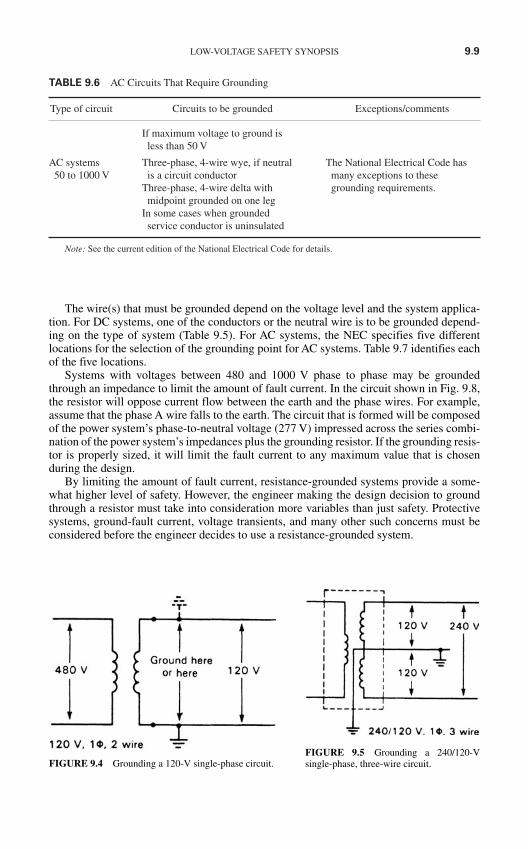
LOW-VOLTAGE SAFETY SYNOPSIS 9.9
TABLE 9.6 AC Circuits That Require Grounding
Type of circuit Circuits to be grounded Exceptions/comments
If maximum voltage to ground is less than 50 V
AC systems Three-phase, 4-wire wye, if neutral The National Electrical Code has 50 to 1000 V is a circuit conductor many exceptions to these
Three-phase, 4-wire delta with grounding requirements.midpoint grounded on one leg
In some cases when grounded service conductor is uninsulated
Note: See the current edition of the National Electrical Code for details.
FIGURE 9.4 Grounding a 120-V single-phase circuit.FIGURE 9.5 Grounding a 240/120-V single-phase, three-wire circuit.
The wire(s) that must be grounded depend on the voltage level and the system applica-tion. For DC systems, one of the conductors or the neutral wire is to be grounded depend-ing on the type of system (Table 9.5). For AC systems, the NEC specifies five differentlocations for the selection of the grounding point for AC systems. Table 9.7 identifies eachof the five locations.
Systems with voltages between 480 and 1000 V phase to phase may be groundedthrough an impedance to limit the amount of fault current. In the circuit shown in Fig. 9.8,the resistor will oppose current flow between the earth and the phase wires. For example,assume that the phase A wire falls to the earth. The circuit that is formed will be composedof the power system’s phase-to-neutral voltage (277 V) impressed across the series combi-nation of the power system’s impedances plus the grounding resistor. If the grounding resis-tor is properly sized, it will limit the fault current to any maximum value that is chosenduring the design.
By limiting the amount of fault current, resistance-grounded systems provide a some-what higher level of safety. However, the engineer making the design decision to groundthrough a resistor must take into consideration more variables than just safety. Protectivesystems, ground-fault current, voltage transients, and many other such concerns must beconsidered before the engineer decides to use a resistance-grounded system.
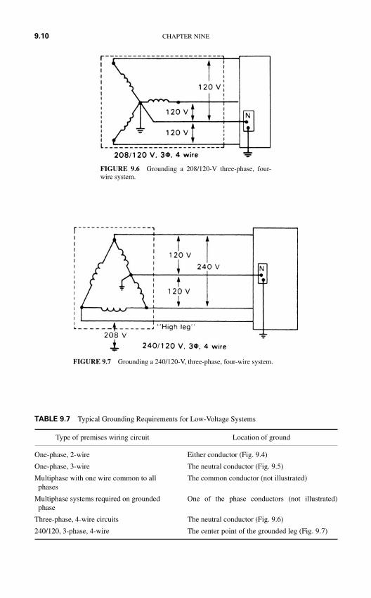
9.10 CHAPTER NINE
FIGURE 9.6 Grounding a 208/120-V three-phase, four-wire system.
FIGURE 9.7 Grounding a 240/120-V, three-phase, four-wire system.
TABLE 9.7 Typical Grounding Requirements for Low-Voltage Systems
Type of premises wiring circuit Location of ground
One-phase, 2-wire Either conductor (Fig. 9.4)
One-phase, 3-wire The neutral conductor (Fig. 9.5)
Multiphase with one wire common to all The common conductor (not illustrated)phases
Multiphase systems required on grounded One of the phase conductors (not illustrated)phase
Three-phase, 4-wire circuits The neutral conductor (Fig. 9.6)
240/120, 3-phase, 4-wire The center point of the grounded leg (Fig. 9.7)
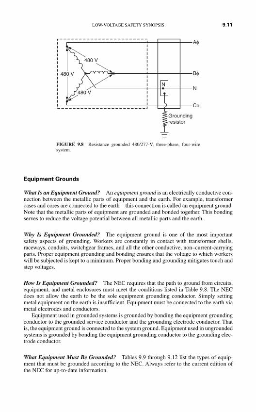
Equipment Grounds
What Is an Equipment Ground? An equipment ground is an electrically conductive con-nection between the metallic parts of equipment and the earth. For example, transformercases and cores are connected to the earth—this connection is called an equipment ground.Note that the metallic parts of equipment are grounded and bonded together. This bondingserves to reduce the voltage potential between all metallic parts and the earth.
Why Is Equipment Grounded? The equipment ground is one of the most importantsafety aspects of grounding. Workers are constantly in contact with transformer shells,raceways, conduits, switchgear frames, and all the other conductive, non–current-carryingparts. Proper equipment grounding and bonding ensures that the voltage to which workerswill be subjected is kept to a minimum. Proper bonding and grounding mitigates touch andstep voltages.
How Is Equipment Grounded? The NEC requires that the path to ground from circuits,equipment, and metal enclosures must meet the conditions listed in Table 9.8. The NECdoes not allow the earth to be the sole equipment grounding conductor. Simply settingmetal equipment on the earth is insufficient. Equipment must be connected to the earth viametal electrodes and conductors.
Equipment used in grounded systems is grounded by bonding the equipment groundingconductor to the grounded service conductor and the grounding electrode conductor. Thatis, the equipment ground is connected to the system ground. Equipment used in ungroundedsystems is grounded by bonding the equipment grounding conductor to the grounding elec-trode conductor.
What Equipment Must Be Grounded? Tables 9.9 through 9.12 list the types of equip-ment that must be grounded according to the NEC. Always refer to the current edition ofthe NEC for up-to-date information.
LOW-VOLTAGE SAFETY SYNOPSIS 9.11
480 V
480 V
480 V
Aφ
Bφ
Cφ
NN
Groundingresistor
FIGURE 9.8 Resistance grounded 480/277-V, three-phase, four-wiresystem.
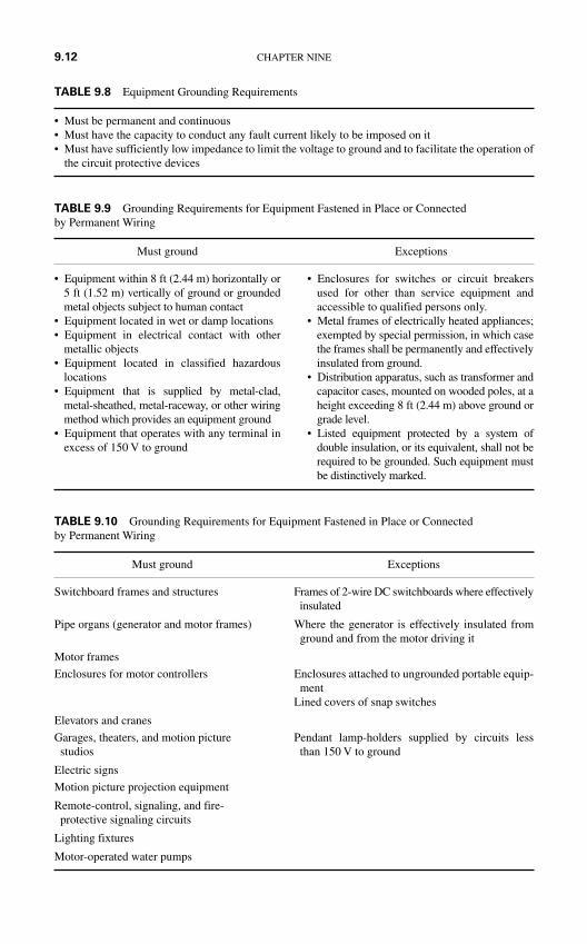
9.12 CHAPTER NINE
TABLE 9.9 Grounding Requirements for Equipment Fastened in Place or Connected by Permanent Wiring
Must ground Exceptions
• Equipment within 8 ft (2.44 m) horizontally or5 ft (1.52 m) vertically of ground or groundedmetal objects subject to human contact
• Equipment located in wet or damp locations• Equipment in electrical contact with other
metallic objects• Equipment located in classified hazardous
locations• Equipment that is supplied by metal-clad,
metal-sheathed, metal-raceway, or other wiringmethod which provides an equipment ground
• Equipment that operates with any terminal inexcess of 150 V to ground
• Enclosures for switches or circuit breakersused for other than service equipment andaccessible to qualified persons only.
• Metal frames of electrically heated appliances;exempted by special permission, in which casethe frames shall be permanently and effectivelyinsulated from ground.
• Distribution apparatus, such as transformer andcapacitor cases, mounted on wooded poles, at aheight exceeding 8 ft (2.44 m) above ground orgrade level.
• Listed equipment protected by a system ofdouble insulation, or its equivalent, shall not berequired to be grounded. Such equipment mustbe distinctively marked.
TABLE 9.10 Grounding Requirements for Equipment Fastened in Place or Connected by Permanent Wiring
Must ground Exceptions
Switchboard frames and structures Frames of 2-wire DC switchboards where effectivelyinsulated
Pipe organs (generator and motor frames) Where the generator is effectively insulated from ground and from the motor driving it
Motor frames
Enclosures for motor controllers Enclosures attached to ungrounded portable equip- ment
Lined covers of snap switches
Elevators and cranes
Garages, theaters, and motion picture Pendant lamp-holders supplied by circuits lessstudios than 150 V to ground
Electric signs
Motion picture projection equipment
Remote-control, signaling, and fire-protective signaling circuits
Lighting fixtures
Motor-operated water pumps
TABLE 9.8 Equipment Grounding Requirements
• Must be permanent and continuous• Must have the capacity to conduct any fault current likely to be imposed on it• Must have sufficiently low impedance to limit the voltage to ground and to facilitate the operation of
the circuit protective devices
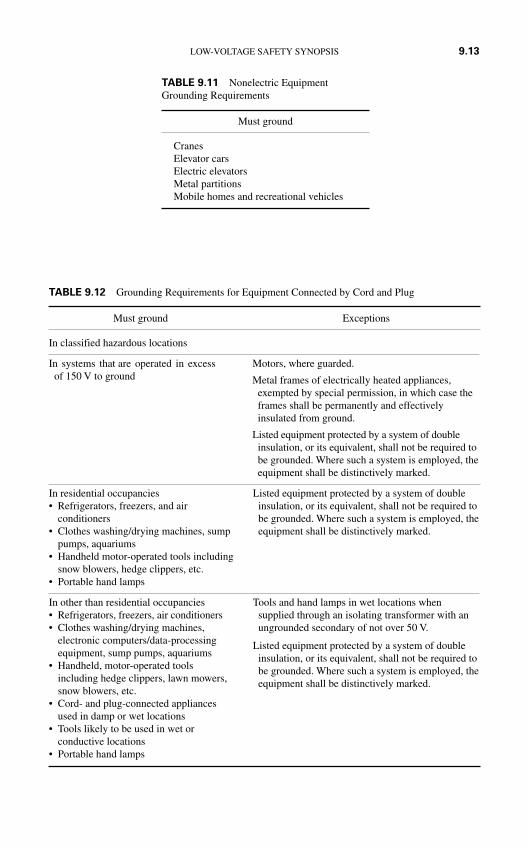
LOW-VOLTAGE SAFETY SYNOPSIS 9.13
TABLE 9.11 Nonelectric EquipmentGrounding Requirements
Must ground
CranesElevator carsElectric elevatorsMetal partitionsMobile homes and recreational vehicles
TABLE 9.12 Grounding Requirements for Equipment Connected by Cord and Plug
Must ground Exceptions
In classified hazardous locations
In systems that are operated in excess Motors, where guarded.of 150 V to ground Metal frames of electrically heated appliances,
exempted by special permission, in which case theframes shall be permanently and effectivelyinsulated from ground.
Listed equipment protected by a system of doubleinsulation, or its equivalent, shall not be required tobe grounded. Where such a system is employed, theequipment shall be distinctively marked.
In residential occupancies• Refrigerators, freezers, and air
conditioners• Clothes washing/drying machines, sump
pumps, aquariums• Handheld motor-operated tools including
snow blowers, hedge clippers, etc.• Portable hand lamps
In other than residential occupancies• Refrigerators, freezers, air conditioners• Clothes washing/drying machines,
electronic computers/data-processingequipment, sump pumps, aquariums
• Handheld, motor-operated tools including hedge clippers, lawn mowers,snow blowers, etc.
• Cord- and plug-connected appliancesused in damp or wet locations
• Tools likely to be used in wet orconductive locations
• Portable hand lamps
Listed equipment protected by a system of doubleinsulation, or its equivalent, shall not be required tobe grounded. Where such a system is employed, theequipment shall be distinctively marked.
Tools and hand lamps in wet locations whensupplied through an isolating transformer with anungrounded secondary of not over 50 V.
Listed equipment protected by a system of doubleinsulation, or its equivalent, shall not be required tobe grounded. Where such a system is employed, theequipment shall be distinctively marked.
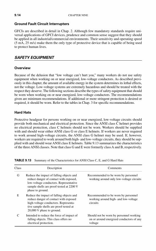
Ground Fault Circuit Interrupters
GFCIs are described in detail in Chap. 2. Although few mandatory standards require uni-versal applications of GFCI devices, prudence and common sense suggest that they shouldbe applied in all industrial/commercial environments. Their sensitivity and operating speed(5 mA, 25 m/s) make them the only type of protective device that is capable of being usedto protect human lives.
SAFETY EQUIPMENT
Overview
Because of the delusion that “low voltage can’t hurt you,” many workers do not use safetyequipment when working on or near energized, low-voltage conductors. As described previ-ously in this chapter, the amount of available energy in the system determines its lethal effects,not the voltage. Low-voltage systems are extremely hazardous and should be treated with therespect they deserve. The following sections describe the types of safety equipment that shouldbe worn when working on or near energized, low-voltage conductors. The recommendationsgiven are minimum recommendations. If additional or more stringent protection is desired orrequired, it should be worn. Refer to the tables in Chap. 3 for specific recommendations.
Hard Hats
Protective headgear for persons working on or near energized, low-voltage circuits shouldprovide both mechanical and electrical protection. Since the ANSI class C helmet providesno electrical protection, class C helmets should not be worn. Workers should be suppliedwith and should wear either ANSI class G or class E helmets. If workers are never requiredto work around high-voltage circuits, the ANSI class G helmet may be used. If, however,workers are required to work around both high- and low-voltage circuits, they should be sup-plied with and should wear ANSI class E helmets. Table 9.13 summarizes the characteristicsof the three ANSI classes. Note that class G and E were formerly class A and B, respectively.
9.14 CHAPTER NINE
TABLE 9.13 Summary of the Characteristics for ANSI Class C, E, and G Hard Hats
Class Description Comments
G Reduce the impact of falling objects and Recommended to be worn by personnelreduce danger of contact with exposed, working around only low-voltage circuitslow-voltage conductors. Representative sample shells are proof-tested at 2200 V phase to ground.
E Reduce the impact of falling objects and Recommended to be worn by personnelreduce danger of contact with exposed working around high- and low-voltagehigh-voltage conductors. Representa- circuitstive sample shells are proof-tested at 20,000 V phase to ground.
C Intended to reduce the force of impact of Should not be worn by personnel workingfalling objects. This class offers no on or around energized conductors of anyelectrical protection. voltage
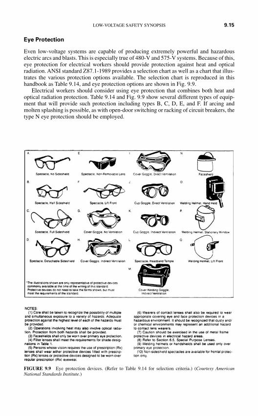
Eye Protection
Even low-voltage systems are capable of producing extremely powerful and hazardouselectric arcs and blasts. This is especially true of 480-V and 575-V systems. Because of this,eye protection for electrical workers should provide protection against heat and opticalradiation. ANSI standard Z87.1-1989 provides a selection chart as well as a chart that illus-trates the various protection options available. The selection chart is reproduced in thishandbook as Table 9.14, and eye protection options are shown in Fig. 9.9.
Electrical workers should consider using eye protection that combines both heat andoptical radiation protection. Table 9.14 and Fig. 9.9 show several different types of equip-ment that will provide such protection including types B, C, D, E, and F. If arcing andmolten splashing is possible, as with open-door switching or racking of circuit breakers, thetype N eye protection should be employed.
LOW-VOLTAGE SAFETY SYNOPSIS 9.15
FIGURE 9.9 Eye protection devices. (Refer to Table 9.14 for selection criteria.) (Courtesy AmericanNational Standards Institute.)

TABLE 9.14 Eye Protection Selection Chart
Assessment Protector Not SEE NOTE (1) typea Protectors Limitations recommended
IMPACT
HEAT
CHEMICAL
DUST
Chipping, grinding,machining, masonrywork, riveting, andsanding
Furnace operations,pouring, casting, hotdipping, gas cutting,and welding
Acid and chemicalshandling, degreasing,and plating
Woodworking, buffing,general dustyconditions
Flying fragments,objects, largechips, particles,sand, dirt, etc.
Hot sparks
Splash frommolten metals
High temperatureexposure
Splash
Irritating mists
Nuisance dust
B, C, D, E, F, G,H, I, J, K,L, N
B, C, D, E, F, G,H, I, J, K,L, *N
*N
N
G, H, K
*N
G
G, H, K
Spectacles, goggles,face shields
SEE NOTES (1) (3) (5)(6) (10).
For severe exposure,add N.
Face shields, goggles,spectacles
*For severe exposure,add N.
SEE NOTES (2) (3).*Face shields worn
over goggles H, KSEE NOTES (2) (3).Screen face shields,
reflective face shieldsSEE NOTES (2) (3).
Goggles, eyecup andcover types
*For severe exposure,add N.
Special-purposegoggles
Goggles, eyecup andcover types
Protective devices do notprovide unlimitedprotection.
SEE NOTE (7).
Spectacles, cup and covertype goggles do not provideunlimited facial protection.
SEE NOTE (2).
SEE NOTE (3).
Ventilation should beadequate but well protectedfrom splash entry.
SEE NOTE (3).
Atmospheric conditions andthe restricted ventilation ofthe protector can causelenses to fog. Frequentcleaning may be required.
Protectors that do notprovide protection fromside exposure.
Filter or tinted lenses thatrestrict lighttransmittance, unless itis determined that aglare hazard exists.Refer to OpticalRadiation.
Protectors that do notprovide protection fromside exposure.
Spectacles, weldinghelmets, hand shields.
9.1
6
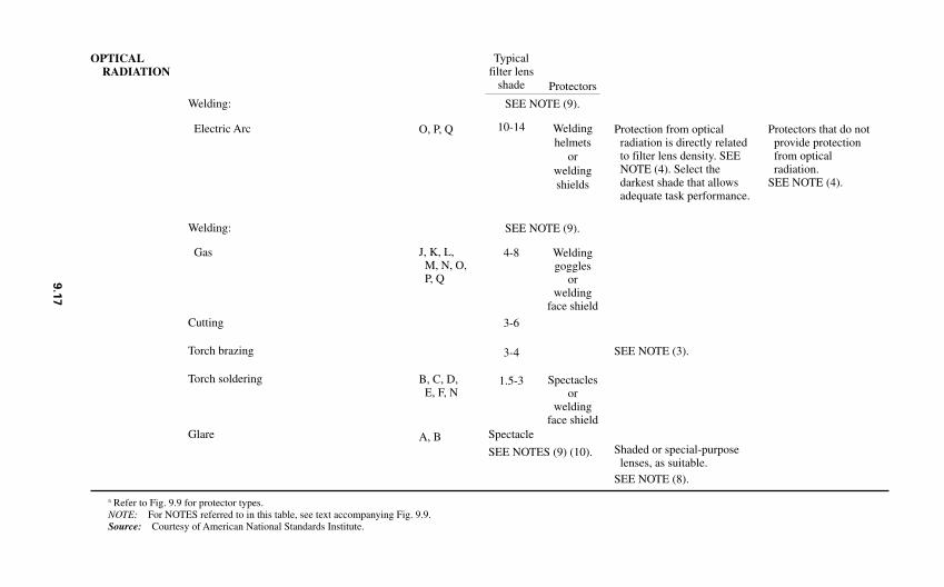
OPTICALRADIATION
Welding:
Electric Arc
Welding:
Gas
Cutting
Torch brazing
Torch soldering
Glare Spectacle
SEE NOTES (9) (10).
a Refer to Fig. 9.9 for protector types.NOTE: For NOTES referred to in this table, see text accompanying Fig. 9.9.Source: Courtesy of American National Standards Institute.
Protectors that do notprovide protection from optical radiation.
SEE NOTE (4).
Protection from opticalradiation is directly relatedto filter lens density. SEENOTE (4). Select thedarkest shade that allowsadequate task performance.
SEE NOTE (3).
Shaded or special-purposelenses, as suitable.
SEE NOTE (8).
O, P, Q
J, K, L, M, N, O,P, Q
B, C, D, E, F, N
A, B
Typicalfilter lens
shade
10-14
4-8
3-6
3-4
1.5-3
Protectors
Weldinghelmets
orweldingshields
Weldinggoggles
orwelding
face shield
Spectaclesor
weldingface shield
SEE NOTE (9).
SEE NOTE (9).
9.1
7
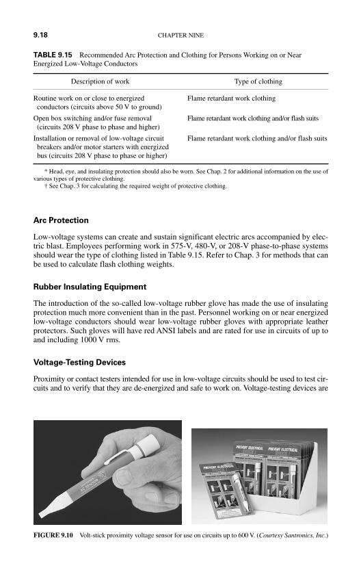
Arc Protection
Low-voltage systems can create and sustain significant electric arcs accompanied by elec-tric blast. Employees performing work in 575-V, 480-V, or 208-V phase-to-phase systemsshould wear the type of clothing listed in Table 9.15. Refer to Chap. 3 for methods that canbe used to calculate flash clothing weights.
Rubber Insulating Equipment
The introduction of the so-called low-voltage rubber glove has made the use of insulatingprotection much more convenient than in the past. Personnel working on or near energizedlow-voltage conductors should wear low-voltage rubber gloves with appropriate leatherprotectors. Such gloves will have red ANSI labels and are rated for use in circuits of up toand including 1000 V rms.
Voltage-Testing Devices
Proximity or contact testers intended for use in low-voltage circuits should be used to test cir-cuits and to verify that they are de-energized and safe to work on. Voltage-testing devices are
9.18 CHAPTER NINE
FIGURE 9.10 Volt-stick proximity voltage sensor for use on circuits up to 600 V. (Courtesy Santronics, Inc.)
TABLE 9.15 Recommended Arc Protection and Clothing for Persons Working on or NearEnergized Low-Voltage Conductors
Description of work Type of clothing
Routine work on or close to energized Flame retardant work clothingconductors (circuits above 50 V to ground)
Open box switching and/or fuse removal Flame retardant work clothing and/or flash suits (circuits 208 V phase to phase and higher)
Installation or removal of low-voltage circuit Flame retardant work clothing and/or flash suitsbreakers and/or motor starters with energized bus (circuits 208 V phase to phase or higher)
* Head, eye, and insulating protection should also be worn. See Chap. 2 for additional information on the use ofvarious types of protective clothing.
† See Chap. 3 for calculating the required weight of protective clothing.
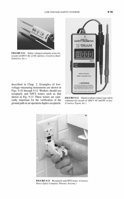
described in Chap. 2. Examples of low-voltage–measuring instruments are shown inFigs. 9.10 through 9.12. Workers should usereceptacle and GFCI testers such as thatshown in Fig. 9.13. These testers are espe-cially important for the verification of theground path in an operation duplex receptacle.
LOW-VOLTAGE SAFETY SYNOPSIS 9.19
FIGURE 9.11 Safety voltage/continuity tester forcircuits of 600 V AC or DC and less. (Courtesy IdealIndustries, Inc.)
FIGURE 9.12 Digital readout contact type safetyvoltmeter for circuits of 1000 V AC and DC or less.(Courtesy Tegam, Inc.)
FIGURE 9.13 Receptacle and GFCI tester. (CourtesyDirect Safety Company, Phoenix, Arizona.)
SAFETY PROCEDURES
General
The general procedures described in Chap. 3 should be used on all circuits in excess of 50 Vto ground. The following sections describe key procedures that apply to low-voltage circuits.
Approach Distances
Although approach distances are laid out in a number of OSHA references, the NFPA 70Eprovides a much more useful and practical concept for approach distances. The followingparagraphs identify methods that may be used to determine approach distances. Refer toChap. 3—Fig. 3.29 and Table 3.15—for reference to the terms used in the following section.
Crossing the Limited Approach Boundary. Unqualified workers are not allowed to crossthe limited approach boundary under any circumstances. Qualified workers may cross thelimited approach boundary if they are qualified to perform the work.
Requirements for Crossing the Restricted Approach Boundary. In order to cross therestricted approach boundary, the following criteria must be met:
The worker must be qualified to do the work. There must be a plan in place that is documented and approved by the employer. The worker must be certain that no part of the body crosses the prohibited approach
boundary. The worker must work to minimize the risk that may be caused by inadvertent movement
by keeping as much of the body out of the restricted space as possible. Allow only pro-tected body parts to enter the restricted space as necessary to complete the work.
Personal protective equipment must be used appropriate for the hazards of the exposedenergized conductor.
Requirements for Crossing the Prohibited Approach Boundary. NFPA 70E considerscrossing the prohibited approach boundary to be the same as working on or contacting an ener-gized conductor. To cross into the prohibited space, the following requirements must be met:
The worker must have specified training required to work on energized conductors or cir-cuit parts.
There must be a plan in place that is documented and approved by the employer. A complete risk analysis must be performed. Authorized management must review and approve the plan and the risk analysis. Personal protective equipment must be used appropriate for the hazards of the exposed
energized conductor.
Voltage Measurement
The voltage-measurement techniques defined in Chap. 3 should be employed on circuits ofall voltages, including 1000 V and below. Note that although the OSHA standards do notrequire the three-step measurement process for circuits of below 600 V, best safety practicedoes, call for instrument checks both before and after the actual circuit measurement.
9.20 CHAPTER NINE
Locking and Tagging
Lockout-tagout and energy control procedures apply to circuits of all voltage levels. Referto Chap. 3 for detailed discussions of lockout-tagout procedures.
Closing Protective Devices After Operation
Workers should never reclose any protective device after it has operated, until it has beendetermined that it is safe to do so. Several criteria may be used to determine whether it issafe to reclose the protective device (Table 9.16). Other conditions may or may not indicatea safe reclosing situation.
ELECTRICAL SAFETY AROUND ELECTRONICCIRCUITS
Modern technology requires many persons to work on or near electronic circuitry. Such cir-cuits can provide special or unusual hazards. The following sections provide informationabout the nature of the hazard and some specific procedures that may be used by workersto enhance their personal safety.
The Nature of the Hazard
Frequencies. The relationship of frequency to electrical hazards is discussed in Chap. 1.Generally, the following points apply:
DC currents and AC currents up to approximately 100 Hz seem to affect the body in a verysimilar manner. For all practical purposes, when working around a DC circuit, the workershould use the same types of procedures as when working around power system frequencies.
Above 100 Hz, the threshold of perception increases. Between 10 and 100 kHz, thethreshold increases from 10 to 100 mA.
Capacitive Discharges. According to the NFPA 70E, the following are true with respectto capacitor discharges:
A current caused by the discharge of a 1-µF, 10,000-V capacitor may cause ventricularfibrillation.
A current caused by the discharge of a 20-µF, 10,000-V capacitor will probably causeventricular fibrillation.
LOW-VOLTAGE SAFETY SYNOPSIS 9.21
TABLE 9.16 Typical Situations That May Allow Reclosing of a Protective Device That Has Operated
• The faulted section of the system is found and repaired.• The nature of the protective device makes it clear that no hazard is present. For example, if the device
that operated is an overload type of device, it may be safe to reclose.• The reclosing operation can be made in such a way that the workers are not exposed to additional
hazard. For example, if the reclosing operation can be made by remote control, and if all personnelare kept away from all parts of the circuit, it may be reclosed.
LOW-VOLTAGE SAFETY SYNOPSIS 9.21
9.22 CHAPTER NINE
Specific Hazards of Electronic Equipment. Although seemingly harmless, electroniccircuits present a number of hazards including
1. Electrical shock from 120-, 240-, or 480-V AC power supplies2. High power supply voltages3. Possible shock and burn hazards caused by radio frequency (RF) fields on or around
antennas and antenna transmission lines4. RF energy–induced voltages5. Ionizing (x-radiation) hazards from magnetrons, klystrons, thyratrons, CRTs, and other
such devices6. Nonionizing RF radiation hazards from
(a) Radar equipment(b) Radio communication equipment(c) Satellite earth-transmitters(d) Industrial scientific and medical equipment(e) RF induction heaters and dielectric heaters(f) Industrial microwave heaters and diathermy radiators
Special Safety Precautions
The following methods are offered in addition to the other safety equipment and proceduresthat are discussed throughout this handbook.
AC and DC Power Supplies. The nature of these hazards is similar to the hazards that arediscussed throughout Chaps. 3 and 9. One piece of equipment that is finding increasing usein protecting workers from these types of hazards is the PVC sheeting that can be placed overthe exposed circuit parts. This PVC material provides an insulating blanket for voltagesup to 1000 V and will allow the worker to perform the necessary tasks in the equipment.
Protection from Shock and Burn Caused by RF Energy on Antennas and/or TransmissionLines. Avoidance of contact is the best possible protection for this type of hazard.Transmitting equipment should always be disabled before workers are allowed to approachantennas or transmission lines.
Electrical Shock Caused by RF-Induced Voltage. Electric shocks from contacting metal-lic objects that have induced RF voltages on them can be dangerous in at least two ways:
1. The surprise effect of the shock can cause the victim to fall from a ladder or other ele-vated location.
2. RF discharge can cause ventricular fibrillation under the right circumstances.
Three methods can be used to protect personnel from induced RF voltages:
1. De-energize the RF circuits to eliminate the energy.
2. Use insulating barriers to isolate the metal objects from the worker.
3. Ground and bond all non–current-carrying metal parts such as chassis, cabinets, covers,and so on. Proper RF ground wires must be very short compared to the wavelength ofthe RF. If a solid ground cannot be reached because of distance, a counterpoise type ofground can be employed. The design of such a ground is beyond the scope of this hand-book. The reader should refer to one of the many engineering texts available.
Radiation (Ionizing and Nonionizing Hazards). The best methods for protecting work-ers from this type of hazard are:
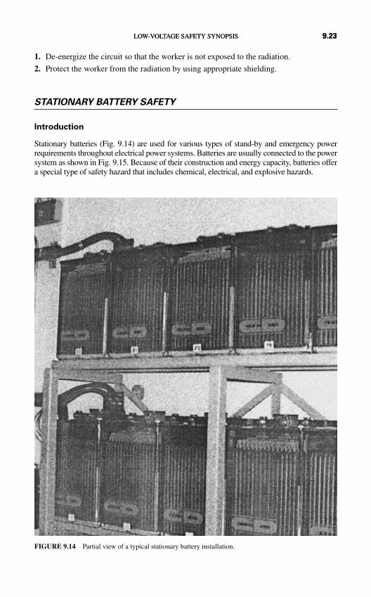
1. De-energize the circuit so that the worker is not exposed to the radiation.
2. Protect the worker from the radiation by using appropriate shielding.
STATIONARY BATTERY SAFETY
Introduction
Stationary batteries (Fig. 9.14) are used for various types of stand-by and emergency powerrequirements throughout electrical power systems. Batteries are usually connected to the powersystem as shown in Fig. 9.15. Because of their construction and energy capacity, batteries offera special type of safety hazard that includes chemical, electrical, and explosive hazards.
FIGURE 9.14 Partial view of a typical stationary battery installation.
LOW-VOLTAGE SAFETY SYNOPSIS 9.23LOW-VOLTAGE SAFETY SYNOPSIS 9.23
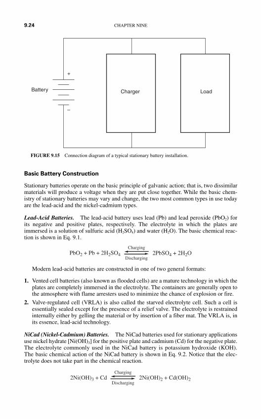
Basic Battery Construction
Stationary batteries operate on the basic principle of galvanic action; that is, two dissimilarmaterials will produce a voltage when they are put close together. While the basic chem-istry of stationary batteries may vary and change, the two most common types in use todayare the lead-acid and the nickel-cadmium types.
Lead-Acid Batteries. The lead-acid battery uses lead (Pb) and lead peroxide (PbO2) forits negative and positive plates, respectively. The electrolyte in which the plates areimmersed is a solution of sulfuric acid (H2SO4) and water (H2O). The basic chemical reac-tion is shown in Eq. 9.1.
Modern lead-acid batteries are constructed in one of two general formats:
1. Vented cell batteries (also known as flooded cells) are a mature technology in which theplates are completely immersed in the electrolyte. The containers are generally open tothe atmosphere with flame arresters used to minimize the chance of explosion or fire.
2. Valve-regulated cell (VRLA) is also called the starved electrolyte cell. Such a cell isessentially sealed except for the presence of a relief valve. The electrolyte is restrainedinternally either by gelling the material or by insertion of a fiber mat. The VRLA is, inits essence, lead-acid technology.
NiCad (Nickel-Cadmium) Batteries. The NiCad batteries used for stationary applicationsuse nickel hydrate [Ni(OH)3] for the positive plate and cadmium (Cd) for the negative plate.The electrolyte commonly used in the NiCad battery is potassium hydroxide (KOH).The basic chemical action of the NiCad battery is shown in Eq. 9.2. Notice that the elec-trolyte does not take part in the chemical reaction.
2Ni(OH)3 + Cd 2Ni(OH)2 + Cd(OH)2
Charging
Discharging
PbO2 + Pb + 2H2SO4 2PbSO4 + 2H2OCharging
Discharging
9.24 CHAPTER NINE
Battery
+
–
Charger Load
FIGURE 9.15 Connection diagram of a typical stationary battery installation.
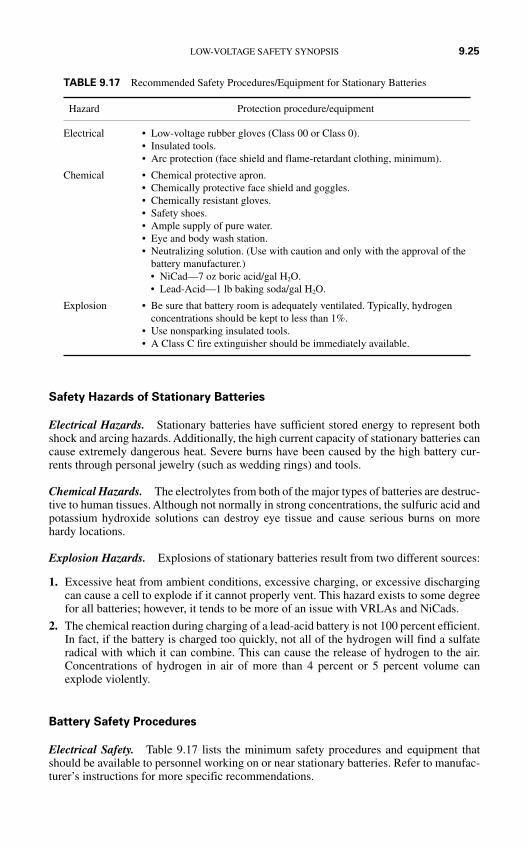
Safety Hazards of Stationary Batteries
Electrical Hazards. Stationary batteries have sufficient stored energy to represent bothshock and arcing hazards. Additionally, the high current capacity of stationary batteries cancause extremely dangerous heat. Severe burns have been caused by the high battery cur-rents through personal jewelry (such as wedding rings) and tools.
Chemical Hazards. The electrolytes from both of the major types of batteries are destruc-tive to human tissues. Although not normally in strong concentrations, the sulfuric acid andpotassium hydroxide solutions can destroy eye tissue and cause serious burns on morehardy locations.
Explosion Hazards. Explosions of stationary batteries result from two different sources:
1. Excessive heat from ambient conditions, excessive charging, or excessive dischargingcan cause a cell to explode if it cannot properly vent. This hazard exists to some degreefor all batteries; however, it tends to be more of an issue with VRLAs and NiCads.
2. The chemical reaction during charging of a lead-acid battery is not 100 percent efficient.In fact, if the battery is charged too quickly, not all of the hydrogen will find a sulfateradical with which it can combine. This can cause the release of hydrogen to the air.Concentrations of hydrogen in air of more than 4 percent or 5 percent volume canexplode violently.
Battery Safety Procedures
Electrical Safety. Table 9.17 lists the minimum safety procedures and equipment thatshould be available to personnel working on or near stationary batteries. Refer to manufac-turer’s instructions for more specific recommendations.
LOW-VOLTAGE SAFETY SYNOPSIS 9.25
TABLE 9.17 Recommended Safety Procedures/Equipment for Stationary Batteries
Hazard Protection procedure/equipment
Electrical • Low-voltage rubber gloves (Class 00 or Class 0).• Insulated tools.• Arc protection (face shield and flame-retardant clothing, minimum).
Chemical • Chemical protective apron.• Chemically protective face shield and goggles.• Chemically resistant gloves.• Safety shoes.• Ample supply of pure water.• Eye and body wash station.• Neutralizing solution. (Use with caution and only with the approval of the
battery manufacturer.)• NiCad—7 oz boric acid/gal H2O.• Lead-Acid—1 lb baking soda/gal H2O.
Explosion • Be sure that battery room is adequately ventilated. Typically, hydrogenconcentrations should be kept to less than 1%.
• Use nonsparking insulated tools.• A Class C fire extinguisher should be immediately available.

This page intentionally left blank
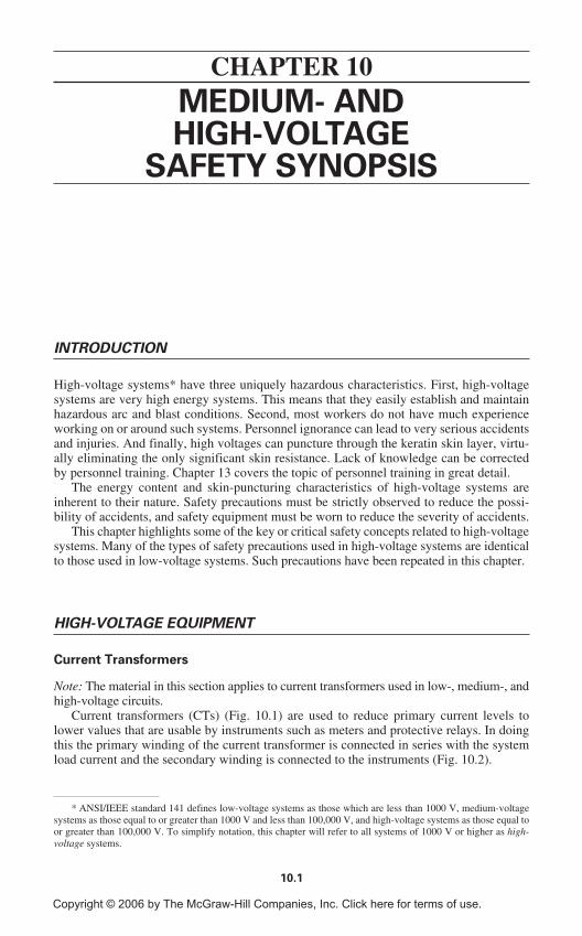
10.1
MEDIUM- ANDHIGH-VOLTAGE
SAFETY SYNOPSIS
INTRODUCTION
High-voltage systems* have three uniquely hazardous characteristics. First, high-voltagesystems are very high energy systems. This means that they easily establish and maintainhazardous arc and blast conditions. Second, most workers do not have much experienceworking on or around such systems. Personnel ignorance can lead to very serious accidentsand injuries. And finally, high voltages can puncture through the keratin skin layer, virtu-ally eliminating the only significant skin resistance. Lack of knowledge can be correctedby personnel training. Chapter 13 covers the topic of personnel training in great detail.
The energy content and skin-puncturing characteristics of high-voltage systems areinherent to their nature. Safety precautions must be strictly observed to reduce the possi-bility of accidents, and safety equipment must be worn to reduce the severity of accidents.
This chapter highlights some of the key or critical safety concepts related to high-voltagesystems. Many of the types of safety precautions used in high-voltage systems are identicalto those used in low-voltage systems. Such precautions have been repeated in this chapter.
HIGH-VOLTAGE EQUIPMENT
Current Transformers
Note: The material in this section applies to current transformers used in low-, medium-, andhigh-voltage circuits.
Current transformers (CTs) (Fig. 10.1) are used to reduce primary current levels tolower values that are usable by instruments such as meters and protective relays. In doingthis the primary winding of the current transformer is connected in series with the systemload current and the secondary winding is connected to the instruments (Fig. 10.2).
CHAPTER 10
* ANSI/IEEE standard 141 defines low-voltage systems as those which are less than 1000 V, medium-voltagesystems as those equal to or greater than 1000 V and less than 100,000 V, and high-voltage systems as those equal toor greater than 100,000 V. To simplify notation, this chapter will refer to all systems of 1000 V or higher as high-voltage systems.
Copyright © 2006 by The McGraw-Hill Companies, Inc. Click here for terms of use.
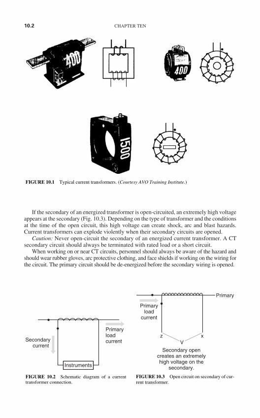
If the secondary of an energized transformer is open-circuited, an extremely high voltageappears at the secondary (Fig. 10.3). Depending on the type of transformer and the conditionsat the time of the open circuit, this high voltage can create shock, arc and blast hazards.Current transformers can explode violently when their secondary circuits are opened.
Caution: Never open-circuit the secondary of an energized current transformer. A CTsecondary circuit should always be terminated with rated load or a short circuit.
When working on or near CT circuits, personnel should always be aware of the hazard andshould wear rubber gloves, arc protective clothing, and face shields if working on the wiring forthe circuit. The primary circuit should be de-energized before the secondary wiring is opened.
10.2 CHAPTER TEN
FIGURE 10.1 Typical current transformers. (Courtesy AVO Training Institute.)
PrimaryloadcurrentSecondary
current
Instruments
FIGURE 10.2 Schematic diagram of a currenttransformer connection.
Primary
Secondary opencreates an extremelyhigh voltage on the
secondary.
z xV
Primaryload
current
FIGURE 10.3 Open circuit on secondary of cur-rent transformer.
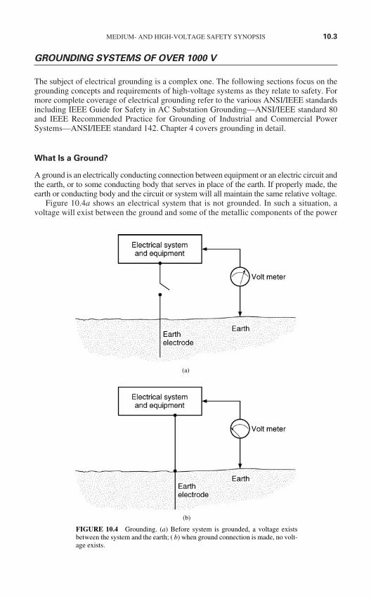
GROUNDING SYSTEMS OF OVER 1000 V
The subject of electrical grounding is a complex one. The following sections focus on thegrounding concepts and requirements of high-voltage systems as they relate to safety. Formore complete coverage of electrical grounding refer to the various ANSI/IEEE standardsincluding IEEE Guide for Safety in AC Substation Grounding—ANSI/IEEE standard 80and IEEE Recommended Practice for Grounding of Industrial and Commercial PowerSystems—ANSI/IEEE standard 142. Chapter 4 covers grounding in detail.
What Is a Ground?
A ground is an electrically conducting connection between equipment or an electric circuit andthe earth, or to some conducting body that serves in place of the earth. If properly made, theearth or conducting body and the circuit or system will all maintain the same relative voltage.
Figure 10.4a shows an electrical system that is not grounded. In such a situation, avoltage will exist between the ground and some of the metallic components of the power
MEDIUM- AND HIGH-VOLTAGE SAFETY SYNOPSIS 10.3
(b)
FIGURE 10.4 Grounding. (a) Before system is grounded, a voltage existsbetween the system and the earth; ( b) when ground connection is made, no volt-age exists.
(a)
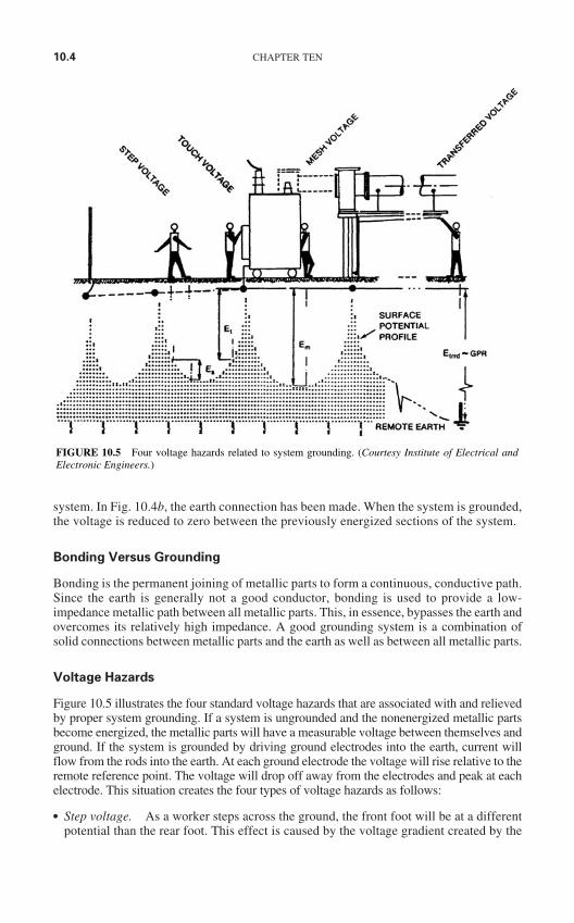
system. In Fig. 10.4b, the earth connection has been made. When the system is grounded,the voltage is reduced to zero between the previously energized sections of the system.
Bonding Versus Grounding
Bonding is the permanent joining of metallic parts to form a continuous, conductive path.Since the earth is generally not a good conductor, bonding is used to provide a low-impedance metallic path between all metallic parts. This, in essence, bypasses the earth andovercomes its relatively high impedance. A good grounding system is a combination ofsolid connections between metallic parts and the earth as well as between all metallic parts.
Voltage Hazards
Figure 10.5 illustrates the four standard voltage hazards that are associated with and relievedby proper system grounding. If a system is ungrounded and the nonenergized metallic partsbecome energized, the metallic parts will have a measurable voltage between themselves andground. If the system is grounded by driving ground electrodes into the earth, current willflow from the rods into the earth. At each ground electrode the voltage will rise relative to theremote reference point. The voltage will drop off away from the electrodes and peak at eachelectrode. This situation creates the four types of voltage hazards as follows:
Step voltage. As a worker steps across the ground, the front foot will be at a differentpotential than the rear foot. This effect is caused by the voltage gradient created by the
10.4 CHAPTER TEN
FIGURE 10.5 Four voltage hazards related to system grounding. (Courtesy Institute of Electrical andElectronic Engineers.)
ground electrodes (Fig. 10.5). Step voltage can easily reach lethal levels. Step voltagecan be mitigated by increasing the number of grounding electrodes, increasing bondingbetween the metal parts, and employing a grounding grid.
Touch voltage. Because of the voltage gradient, the voltage of the earth, only a shortdistance from the grounded metallic equipment, will be different than the equipment.Thus if a worker touches the grounded equipment, his or her feet will be at a differentpotential than his or her hands. This voltage can be lethal. Touch voltage is mitigated byincreasing the number of grounding electrodes, increasing bonding between metal parts,and employing a grounding grid.
Mesh voltage. Mesh voltage is the worst case of touch voltage. Cause, effect, and mit-igation methods are identical to those described previously under Touch voltage.
Transferred voltage. Because metal parts have a much lower impedance than the earth,the voltage drop between remote locations is lower on the metallic connections than theearth. This means that the earth may be at a significantly different voltage than the metal-lic connections. Transferred voltages are particularly noticeable on neutral wires, whichare grounded at the service point and nowhere else. Transferred potential can be mitigatedby providing the entire area with a ground grid; however, this solution is infeasible in anybut the smallest systems. Transferred voltage must be mitigated by avoiding contact withconductors from remote locations and/or using rubber insulating gloves.
System Grounds
What Is a System Ground? A system ground is the connection of one of the conductorsto the earth. Such a connection is accomplished by connecting an electric wire to theselected system conductor and the grounding electrode.
Why Are Systems Grounded? Power systems have conductors grounded for a variety ofsafety and operational reasons including
Grounded systems provide sufficient short-circuit current for efficient operation of pro-tective equipment.
Grounded systems are less prone to transient overvoltages that can cause insulationfailures.
Grounded systems are generally more easily protected from lightning. Solidly grounded systems are less prone to resonant conditions that can cause equipment
and insulation failures.
What Systems Must Be Grounded? The NEC allows the grounding of permanentlyinstalled electrical utilization systems and requires the grounding of mobile electrical sup-ply systems. If the mobile supply system is supplied by a high-voltage delta system, theNEC requires that a ground be derived using a grounding transformer. The NationalElectrical Safety Code requires that electric utility supply systems be grounded.
How Are Systems Grounded? Electrical systems are grounded by connecting one of theelectrical conductors to earth. The conductor chosen and the location of the ground aredetermined as part of the engineering design for the system. With systems that have deltatransformer or generator windings, the neutral, and therefore the ground point, can bederived by using a grounding transformer. Figure 10.6 shows a grounded wye-delta trans-former used to derive a system neutral and ground. Figure 10.7 shows a zigzag transformerused for the same purpose.
MEDIUM- AND HIGH-VOLTAGE SAFETY SYNOPSIS 10.5
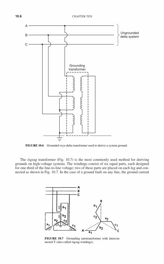
The zigzag transformer (Fig. 10.7) is the most commonly used method for derivinggrounds on high-voltage systems. The windings consist of six equal parts, each designedfor one-third of the line-to-line voltage; two of these parts are placed on each leg and con-nected as shown in Fig. 10.7. In the case of a ground fault on any line, the ground current
10.6 CHAPTER TEN
Ungroundeddelta system
A
B
C
Groundingtransformer
FIGURE 10.6 Grounded wye-delta transformer used to derive a system ground.
FIGURE 10.7 Grounding autotransformer with intercon-nected Y (also called zigzag windings).
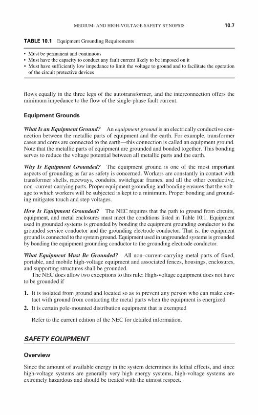
flows equally in the three legs of the autotransformer, and the interconnection offers theminimum impedance to the flow of the single-phase fault current.
Equipment Grounds
What Is an Equipment Ground? An equipment ground is an electrically conductive con-nection between the metallic parts of equipment and the earth. For example, transformercases and cores are connected to the earth—this connection is called an equipment ground.Note that the metallic parts of equipment are grounded and bonded together. This bondingserves to reduce the voltage potential between all metallic parts and the earth.
Why Is Equipment Grounded? The equipment ground is one of the most importantaspects of grounding as far as safety is concerned. Workers are constantly in contact withtransformer shells, raceways, conduits, switchgear frames, and all the other conductive,non–current-carrying parts. Proper equipment grounding and bonding ensures that the volt-age to which workers will be subjected is kept to a minimum. Proper bonding and ground-ing mitigates touch and step voltages.
How Is Equipment Grounded? The NEC requires that the path to ground from circuits,equipment, and metal enclosures must meet the conditions listed in Table 10.1. Equipmentused in grounded systems is grounded by bonding the equipment grounding conductor to thegrounded service conductor and the grounding electrode conductor. That is, the equipmentground is connected to the system ground. Equipment used in ungrounded systems is groundedby bonding the equipment grounding conductor to the grounding electrode conductor.
What Equipment Must Be Grounded? All non–current-carrying metal parts of fixed,portable, and mobile high-voltage equipment and associated fences, housings, enclosures,and supporting structures shall be grounded.
The NEC does allow two exceptions to this rule: High-voltage equipment does not haveto be grounded if
1. It is isolated from ground and located so as to prevent any person who can make con-tact with ground from contacting the metal parts when the equipment is energized
2. It is certain pole-mounted distribution equipment that is exempted
Refer to the current edition of the NEC for detailed information.
SAFETY EQUIPMENT
Overview
Since the amount of available energy in the system determines its lethal effects, and sincehigh-voltage systems are generally very high energy systems, high-voltage systems areextremely hazardous and should be treated with the utmost respect.
MEDIUM- AND HIGH-VOLTAGE SAFETY SYNOPSIS 10.7
TABLE 10.1 Equipment Grounding Requirements
• Must be permanent and continuous• Must have the capacity to conduct any fault current likely to be imposed on it• Must have sufficiently low impedance to limit the voltage to ground and to facilitate the operation
of the circuit protective devices
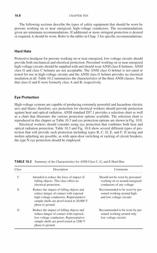
The following sections describe the types of safety equipment that should be worn bypersons working on or near energized, high-voltage conductors. The recommendationsgiven are minimum recommendations. If additional or more stringent protection is desiredor required, it should be worn. Refer to the tables in Chap. 3 for specific recommendations.
Hard Hats
Protective headgear for persons working on or near energized, low-voltage circuits shouldprovide both mechanical and electrical protection. Personnel working on or near energizedhigh-voltage circuits should be supplied with and should wear ANSI class E helmets. ANSIclass G and class C helmets are not acceptable. The ANSI class G helmet is not rated ortested for use in high-voltage circuits and the ANSI class G helmet provides no electricalinsulation at all. Table 10.2 summarizes the characteristics of the three ANSI classes. Notethat class G and E were formerly class A and B, respectively.
Eye Protection
High-voltage systems are capable of producing extremely powerful and hazardous electricarcs and blasts; therefore, eye protection for electrical workers should provide protectionagainst heat and optical radiation. ANSI standard Z87.1 provides a selection chart as wellas a chart that illustrates the various protection options available. The selection chart isreproduced in this chapter as Table 10.3 and eye protection options are shown in Fig. 10.8.
Electrical workers should consider using eye protection that combines both heat andoptical radiation protection. Table 10.3 and Fig. 10.8 show several different types of pro-tection that will provide such protection including types B, C, D, E, and F. If arcing andmolten splashing are possible, as with open-door switching or racking of circuit breakers,the type N eye protection should be employed.
10.8 CHAPTER TEN
TABLE 10.2 Summary of the Characteristics for ANSI Class C, G, and E Hard Hats
Class Description Comments
C Intended to reduce the force of impact of Should not be worn by personnel falling objects. This class offers no working on or around energized electrical protection. conductors of any voltage
E Reduce the impact of falling objects and Recommended to be worn by per-reduce danger of contact with exposed sonnel working around high- high-voltage conductors. Representative and low-voltage circuitssample shells are proof-tested at 20,000 V phase to ground.
G Reduce the impact of falling objects and Recommended to be worn by per-reduce danger of contact with exposed, sonnel working around only low-voltage conductors. Representative low-voltage circuitssample shells are proof-tested at 2200 V phase to ground.
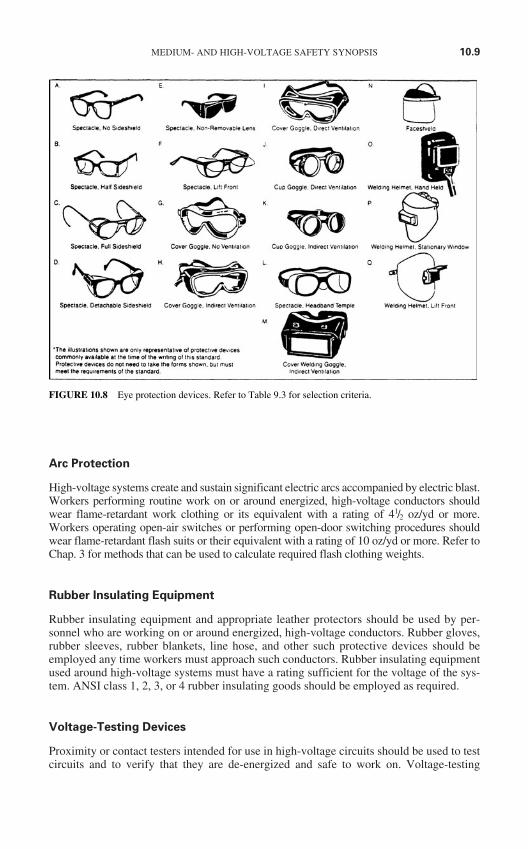
Arc Protection
High-voltage systems create and sustain significant electric arcs accompanied by electric blast.Workers performing routine work on or around energized, high-voltage conductors shouldwear flame-retardant work clothing or its equivalent with a rating of 41/2 oz/yd or more.Workers operating open-air switches or performing open-door switching procedures shouldwear flame-retardant flash suits or their equivalent with a rating of 10 oz/yd or more. Refer toChap. 3 for methods that can be used to calculate required flash clothing weights.
Rubber Insulating Equipment
Rubber insulating equipment and appropriate leather protectors should be used by per-sonnel who are working on or around energized, high-voltage conductors. Rubber gloves,rubber sleeves, rubber blankets, line hose, and other such protective devices should beemployed any time workers must approach such conductors. Rubber insulating equipmentused around high-voltage systems must have a rating sufficient for the voltage of the sys-tem. ANSI class 1, 2, 3, or 4 rubber insulating goods should be employed as required.
Voltage-Testing Devices
Proximity or contact testers intended for use in high-voltage circuits should be used to testcircuits and to verify that they are de-energized and safe to work on. Voltage-testing
MEDIUM- AND HIGH-VOLTAGE SAFETY SYNOPSIS 10.9
FIGURE 10.8 Eye protection devices. Refer to Table 9.3 for selection criteria.
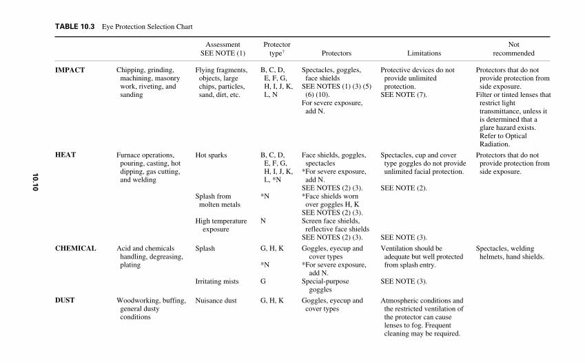
TABLE 10.3 Eye Protection Selection Chart
Assessment Protector Not SEE NOTE (1) type† Protectors Limitations recommended
IMPACT
HEAT
CHEMICAL
DUST
Chipping, grinding,machining, masonrywork, riveting, andsanding
Furnace operations,pouring, casting, hotdipping, gas cutting,and welding
Acid and chemicalshandling, degreasing,plating
Woodworking, buffing,general dustyconditions
Flying fragments,objects, largechips, particles,sand, dirt, etc.
Hot sparks
Splash frommolten metals
High temperatureexposure
Splash
Irritating mists
Nuisance dust
B, C, D, E, F, G,H, I, J, K,L, N
B, C, D, E, F, G,H, I, J, K,L, *N
*N
N
G, H, K
*N
G
G, H, K
Spectacles, goggles,face shields
SEE NOTES (1) (3) (5)(6) (10).
For severe exposure,add N.
Face shields, goggles,spectacles
*For severe exposure,add N.
SEE NOTES (2) (3).*Face shields worn
over goggles H, KSEE NOTES (2) (3).Screen face shields,
reflective face shieldsSEE NOTES (2) (3).
Goggles, eyecup andcover types
*For severe exposure,add N.
Special-purposegoggles
Goggles, eyecup andcover types
Protective devices do notprovide unlimitedprotection.
SEE NOTE (7).
Spectacles, cup and covertype goggles do not provideunlimited facial protection.
SEE NOTE (2).
SEE NOTE (3).
Ventilation should beadequate but well protectedfrom splash entry.
SEE NOTE (3).
Atmospheric conditions andthe restricted ventilation ofthe protector can causelenses to fog. Frequentcleaning may be required.
Protectors that do notprovide protection fromside exposure.
Filter or tinted lenses thatrestrict lighttransmittance, unless itis determined that aglare hazard exists.Refer to OpticalRadiation.
Protectors that do notprovide protection fromside exposure.
Spectacles, weldinghelmets, hand shields.
10.1
0
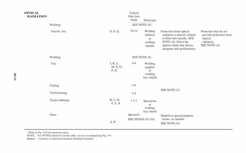
OPTICALRADIATION
Welding:
Electric Arc
Welding:
Gas
Cutting
Torch brazing
Torch soldering
Glare Spectacle
SEE NOTES (9) (10).
† Refer to Fig. 10.8 for protector types.NOTE: For NOTES referred to in this table, see text accompanying Fig. 9.9.Source: Courtesy of American National Standards Institute.
Protectors that do notprovide protection fromopticalradiation.
SEE NOTE (4).
Protection from opticalradiation is directly relatedto filter lens density. SEENOTE (4). Select thedarkest shade that allowsadequate task performance.
SEE NOTE (3).
Shaded or special-purposelenses, as suitable.
SEE NOTE (8).
O, P, Q
J, K, L, M, N, O,P, Q
B, C, D, E, F, N
A, B
Typicalfilter lens
shade
10-14
4-8
3-6
3-4
1.5-3
Protectors
Weldinghelmets
orweldingshields
Weldinggoggles
orwelding
face shield
Spectaclesor
weldingface shield
SEE NOTE (9).
SEE NOTE (9).
10.1
1
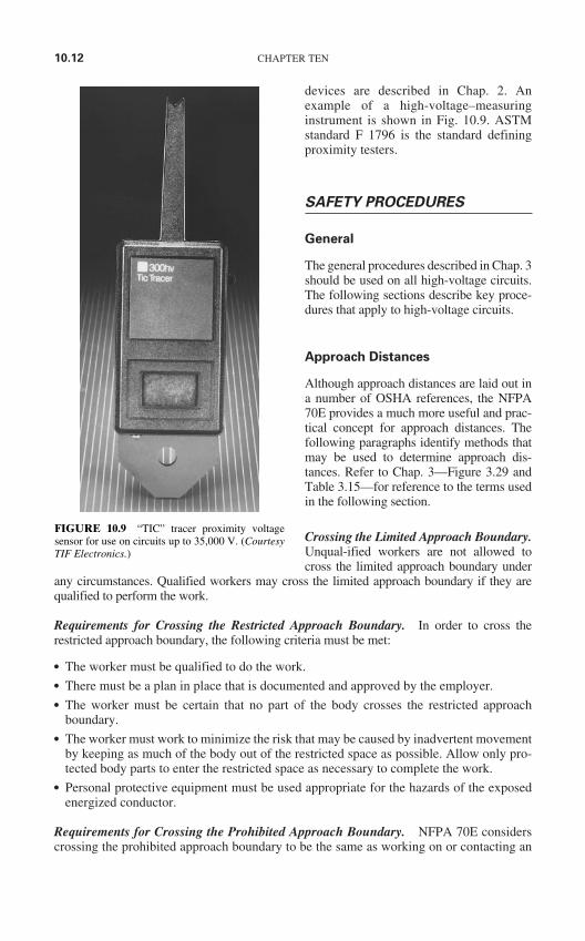
devices are described in Chap. 2. Anexample of a high-voltage–measuringinstrument is shown in Fig. 10.9. ASTMstandard F 1796 is the standard definingproximity testers.
SAFETY PROCEDURES
General
The general procedures described in Chap. 3should be used on all high-voltage circuits.The following sections describe key proce-dures that apply to high-voltage circuits.
Approach Distances
Although approach distances are laid out ina number of OSHA references, the NFPA70E provides a much more useful and prac-tical concept for approach distances. Thefollowing paragraphs identify methods thatmay be used to determine approach dis-tances. Refer to Chap. 3—Figure 3.29 andTable 3.15—for reference to the terms usedin the following section.
Crossing the Limited Approach Boundary.Unqual-ified workers are not allowed tocross the limited approach boundary under
any circumstances. Qualified workers may cross the limited approach boundary if they arequalified to perform the work.
Requirements for Crossing the Restricted Approach Boundary. In order to cross therestricted approach boundary, the following criteria must be met:
The worker must be qualified to do the work. There must be a plan in place that is documented and approved by the employer. The worker must be certain that no part of the body crosses the restricted approach
boundary. The worker must work to minimize the risk that may be caused by inadvertent movement
by keeping as much of the body out of the restricted space as possible. Allow only pro-tected body parts to enter the restricted space as necessary to complete the work.
Personal protective equipment must be used appropriate for the hazards of the exposedenergized conductor.
Requirements for Crossing the Prohibited Approach Boundary. NFPA 70E considerscrossing the prohibited approach boundary to be the same as working on or contacting an
10.12 CHAPTER TEN
FIGURE 10.9 “TIC” tracer proximity voltagesensor for use on circuits up to 35,000 V. (CourtesyTIF Electronics.)
energized conductor. To cross into the prohibited space, the following requirements mustbe met:
The worker must have specified training required to work on energized conductors or cir-cuit parts.
There must be a plan in place that is documented and approved by the employer. A complete risk analysis must be performed. Authorized management must review and approve the plan and the risk analysis. Personal protective equipment must be used appropriate for the hazards of the exposed
energized conductor.
Voltage Measurement
The voltage-measurement techniques defined in Chap. 3 should be employed on circuits ofall voltages.
Locking and Tagging
Lockout-tagout and energy control procedures apply to circuits of all voltage levels. Referto Chap. 3 for detailed discussions of lockout-tagout procedures.
Closing Protective Devices After Operation
Workers should never reclose any protective device after it has operated, until it has beendetermined that it is safe to do so. Several criteria may be used to determine whether it issafe to reclose the protective device (Table 10.4).
Other conditions may or may not indicate a safe reclosing situation. ANSI/IEEE stan-dard 141 defines low-voltage systems as those that are less than 1000 V, medium-voltagesystems as those equal to or greater than 1000 V and less than 100,000 V, and high-voltagesystems as those equal to or greater than 100,000 V. To simplify this notation, this chapterwill refer to all systems of 1000 V or higher as high-voltage systems.
MEDIUM- AND HIGH-VOLTAGE SAFETY SYNOPSIS 10.13
TABLE 10.4 Typical Situations That May Allow Reclosing of a Protective Device That Has Operated
• The faulted section of the system is found and repaired.• The nature of the protective device makes it clear that no hazard is present. For example, if the device
that operated is an overload type of device, it may be safe to reclose.• The reclosing operation can be made in such a way that the workers are not exposed to additional
hazard. For example, if the reclosing operation can be made by remote control, and if all personnelare kept away from all parts of the circuit, it may be reclosed.

This page intentionally left blank
HUMAN FACTORS INELECTRICAL SAFETY
INTRODUCTION
In this chapter, the topic of human factors is reviewed in the context of electrical safety.Background information is followed by examples for power systems. Brief discussion isalso presented on the topics of visualization and cognitive ergonomics.
Background
The topic of human factors evolves from the obvious statement that, “People are notmachines.” In the early 19th century, during the early periods of industrialization, a persis-tent question was how to optimize the placement of people in “machine systems.” Pre-datingelectrical power, when jobs involved assembly line operations with repetitive tasks requir-ing uniformity and efficiency of physical movements between operations, materials, andemployees, studies of “time-and-motion” and human “anthropomorphics,” or “averagebody part sizes” were used by management to figure out problems, like “how far can anaverage worker reach to push or pull this piece” on the assembly line.
In the early 20th century, as electrification enabled industrialization to move beyond man-ufacturing across all economic sectors, the complexity of machine systems increased. Morethan one process could be pulled into a work environment, leading to multiple operations sit-uated in geographic proximity, running concurrently, and producing output at high speeds.
With electrification, increasing industrial complexity, and faster production rates, thedemands on people working with the machine systems grew. As suggested by Rasmussen1
at this stage, human factors more commonly studied measures of human physical abilitiesalong with measures of physical reliability. In this context, “knob-and-dial” ergonomicswas a research focus, for example, identifying the correct size of knob for an employee toeasily grasp doing a turning task, and measuring how often the knob would be incorrectlyversus correctly turned.
Then, in the 1930s, Rasmussen notes that as automation was introduced into the chem-ical process industries, the link between machines and people often became indirect. Theinterface of automatic control engineering made the wide reach of individual employeespossible over large scale and significantly hazardous production.
As production failures occurred, interest in human factors extended from human“physical” reliability to include the reliability people might show in understandingprocess information and executing successful decisions. This specialty later became knownas cognitive ergonomics.
CHAPTER 11
11.1
Copyright © 2006 by The McGraw-Hill Companies, Inc. Click here for terms of use.
Then “human error” research developed as an aspect of human factors studies, with thegoal being to break down or untangle causes of human physical and/or cognitive malfunctionfrom machine or process malfunction in post-accident studies. In anticipation of installationdesign and development, human error probability, or human reliability assessment (HRA)also came into human factors consideration as part of operational engineering analysis.
In the mid-20th century, military experience in World War II aviation and the post-WorldWar II growth in civilian aviation added more information about how humans and engineeredsystems could interact with potentially tragic results of plane crashes. By the early 1970s, gen-erally accepted ideas about how to evaluate the fit between work and workers were maturinginto an accepted professional approach within the industrial engineering community.
Concurrently, within the electrical power industry, the post-World War II develop-ment of the civilian nuclear power industry resulted in an active transfer of human fac-tor’s ideas into the management of civilian nuclear power operations. This developmentbecame more substantial following two major tragedies: the Unit 2 scram at the ThreeMile Island Power Station (TMI-2) in Pennsylvania on March 28, 1979; and the explo-sion of Unit 4 of the Chernobyl Nuclear Power Station in the Ukrainian former SovietUnion on April 26, 1986.2
With TMI-2 and Chernobyl, nations learned that human error in complex operationalenvironments producing electrical power could potentially result in global disaster.Investigations identified human factors in the causal chain of events leading to these disas-ters. This learning created additional focus on basic concepts of human performance.
Continuing to the present, the topics of human factors have moved beyond “humanmachine interactions”3 to “human-systems interfaces” or HIS4. The term human factors mayhave two meanings. Human factors may refer to various traits or “elements of the human”2 asindividuals which should be considered for safe and effective results from engineered systems.Or, the term may mean the applied science technology relating fundamental human sciences(like anatomy, physiology, neuro-psychology) to industrial systems.2
To illustrate these definitions, consider that electrical work demands intense integrationof visual and spatial information to successfully complete tasks. Anything that inhibits anemployee’s vision creates risk for an electrical event. Considering the two definitions ofhuman factors applied to vision, as a human factor relating to the individual, vision may beunderstood as limited to the measurement of visual acuity (or accuracy of how well anemployee sees a wall chart) to ensure that they have adequate vision ability to read a com-puter screen or see a stoplight; or the factor may be as complicated as the engineeringadvancement of vision assistance devices, such as these examples:
Infrared cameras installed in vehicle dashboards for night driving Infrared intrusion detection systems Infrared monitors used in heat tracing as a safety monitoring strategy to identify exces-
sive ohmic heating of installed conductors
For an individual, vision is a critically important human factor. About 80 percent of infor-mation about machines and systems comes to employees via their vision.5 Note visual acuitiesgo down as the complexity of the visual target increases. In other words, when there is moreto look at, it is harder to see. Multiple physical factors influence visual acuity, including:
Illumination Contrast Time of exposure to the visual target Color of the visual target and the target’s background
11.2 CHAPTER ELEVEN
The smallest detectable threshold for vision is 10−6 milliliter (mL). Vision ability isdecreased with vibration, hypoxia or low oxygen, and motion of the visual target.
POWER SYSTEMS AND HUMAN FACTORS
As the previous comments suggest, the power industry has significantly contributed tounderstanding about human factors. Here further examples of human factors in the electri-cal industry are presented. In Table 11.1, selected workplace environments are identified.
The generation, transmission, distribution, design, installation, operation, and mainte-nance of electrical power happens in diverse situations. Given the diversity in workplaces,the human factors of relevance to electrical safety depend in part on where in the power sys-tem the employee may be working. An employee assigned to a control room at a nuclearpower station can reasonably be expected to confront demands in his/her work that differcompared to an employee wiring a house under construction or doing maintenance in acogeneration facility. So, it follows then that the human factors in a control room can beexpected to differ from those at the construction site.
HUMAN FACTORS IN ELECTRICAL SAFETY 11.3
TABLE 11.1 Power Systems Environments and Human Factors Examples
Workplace Human factors considerations
Generation Dust, fumes, noise in fossil fuel environmentsCommon features to control rooms,11 including
Compact workstations using visual displaysLarge overview displaysIncreased cognitive workloads as staffing changesInformation multiplicity
Virtual workspaces4 withSerial access to information & controlsMore time spent on secondary tasks
Transmission Live line work,12 withHelicopter approaches at high elevationsMoving parts (Helicopter rotars)Required calculations: minimum approach distance
Placing Person with Tools in Air Gap13
Distribution Voltage protection personal equipment, includingRubber goodsExtended tool handles
Recognition of minimal power line approach distancesAt or above shoulder work requiring stressful posturesWork in vaults or confined space requiring respiratorsRepetive motion and lifting heavy loads14
Construction Crouching, kneeling, or reaching in various spacesVibration in powered equipmentEnvironmental temperature extremesHeavy equipment operation, with noise, moving parts Potential contact with power lines above and below
The influence of the environment on human factors is not isolated. Relating Hawkins’6
“SHEL” illustration of this concept, Kawano2 describes the acronym as:
S – for software, including for example, computer software, paper documents or instruc-tions, permits, or procedures
H – for hardware, or the engineered or constructed aspects of the environment E – for the environment or ambient conditions, such as geography, meteorology, humidity,
or altitude L – for “liveware,” or the people involved directly or indirectly in the work situation
Kawano adds an “m” to Hawkins’ SHEL acronym, to include managing systems as adynamic and represented part of the model. As suggested by Hawkins and amended byKawano, the m-SHEL model provides a step towards an integrated systems approach tohuman factors. The model offers another strategy for thinking about electrical safety so thatthe programmatic focus goes beyond the individual to include the technologies, engineer-ing, interpersonal, and environmental contributions to the individual’s experience in thesystem of production where they work.
Visualization
Rasmussen1 has suggested that automation relieved employees of repetitive manual tasks;consequently, work with more decision-making or trouble-shooting content became commonin the industrial setting. Today, information technology, including the use of computer-basedapproaches, has placed volumes of data at the center of employee tasks.
Tory and Moller7 describe the methods available with computer visualization andgraphics which can support perception and cognition, or the human abilities to sense (viaeyes, ears, nose, taste, touch) and think. Table 11.2 gives electrical safety examples wherethese methods can serve as cognitive aids.
Cognitive Ergonomics
The early 21st century is notable for the promise of new horizons in research advancingcognitive ergonomics to fully benefit the industrial workplace. As brain science maps the
11.4 CHAPTER ELEVEN
TABLE 11.2 Electrical Safety Examples of Cognitive Aids with Computer Visualization Technologies
Cognitive Challenge Visualization method
Multiple permits per job step Reducing search via data grouping or structurewith multiple steps in a job
Monitoring for breaker trips, Perceptual monitoring using pre-attentive power surges, or faults visual characteristics
Switching procedures in Enhancing data recognition, abstraction, andpower outage or routine aggregationmaintenance
Note: Visualization methods are based on Table 1 of Tory and Moller’s report,7 which isadapted in part from work by Card, et al. in Information Visualization: Using Vision to Think. SanFrancisco: Morgan Kaufmann Publishers, 1999.
terrain of thought and mind-body interactions using scanning technologies like magneticresonance imaging (MRI), positron emission tomography (PET), and photon emissioncomputerized tomography (SPECT), data is accumulating to explain how people think indifferent scenarios.
A key insight from this research is that context is hugely influential over thought. Using themetaphor of the brain as a computer, one way to appreciate the role of context is to suggest thatno person comes to his/her work with a “blank hard drive or screen.” Rather people do theirjobs with the advantage and disadvantage of what they see, hear, smell, and touch in their sur-rounding; what they believe; and how they physically feel. This information loads the “driveand screen” occupying space alongside of where “the programs run” or thought happens.
Cognitive ergonomics specifically addresses how to modify what occupies an employee’s“hard drive and screen” when work is being done, to improve the way thought unfolds, andthereby, improve decisions.
Context can be appreciated not simply as a physical background to the employee.Context can also be in the form of background beliefs or work myths. The dictionarydefines a myth as “an old traditional story or legend, especially one concerning fabulous orsupernatural beings, giving expression to early beliefs, aspirations, and perceptions of apeople and serving to explain natural phenomena or the origins of a people.”8
Following are examples of myths which can affect electrical safety. Exploring thesemyths offers promise to improve electrical safety by reducing the chance that an employeewill act based on an inaccurate background belief.
“I’m experienced, so I won’t get injured.” This belief assumes that experiences protectagainst injury and death. However, as the statistics shown in Chap. 8 suggest, the employeewho is most at risk of an electrical event is between the ages of 25 to 45 years and with acci-dent-free years on the job. To the extent that an employee’s experience dulls his/her aware-ness of the distinctive features present in the job he/she is immediately doing, his/herexperience may create a false context for thinking about situational facts like:
Task electrical configuration Personal protection and barrier needs Required resources (like people, equipment, and time) to complete the job
“Electrical accidents happen when an employee isn’t paying attention.” This mythicbelief is based on a logic that goes as follows: As long as an employee does pay attention,no accidents will occur; therefore, if an accident happens, an employee must have beeninattentive.
As an explanation for electrical events, inattention is assumed by the comments like:
“He wandered off in his thinking.” “He was daydreaming on the job.” “He was worried about something else.”
However, through many debriefing of electrical accidents, engineers have come toappreciate modern electrical work unfolds in highly complicated situations. If an electricalsafety failure occurs, typically more than one thing goes wrong. Multiple system faults orpersonnel errors contribute to the event. This understanding suggests that attention alone isnot sufficient to prevent an electrical accident. Given the embedded complexity in thepower system, multiple actions are required to preserve safety. How to sharpen or focus theactions of human attention is a research target of cognitive ergonomics.
HUMAN FACTORS IN ELECTRICAL SAFETY 11.5
Related to attention is the ability to hear. If an employee cannot hear instructions he isbeing given verbally, that employee can be expected to have difficulty in his/her focus onthe instructions or attention to the verbal guidance given. Hearing as a limited human factordepends on sound. Sound pressures needed for hearing are a function of the material ormedia (for example, air) through which the sound or acoustic waves are propagating.5 Thethreshold for hearing in the frequency range of the spoken word, from about 1,000 to 5,000 Hz,is about 20 µPascals (2.9 109 psi).
According to Chapanis, there are multiple aspects to a listener’s ability to detect sound,including:
The listener’s age The listener’s history of past or ongoing noise exposure Whether the listener is using one ear or two to hear, with the use on one ear (mono-aural
listening) requiring 3 decibels (dB) more sound pressure The sound’s acoustic frequency, expressed in hertz (Hz) The presence of competing sounds or masking The complexity of the bandwidth tones The sound’s duration, with durations less than 200 mili-seconds (ms) requiring increased
intensity (that is, as acoustic signal duration is halved, the intensity of the signal mustdouble to be audible).
Returning to the M-SHEL model of human factors, the interaction of “liveware” or peo-ple depends on successful communication. To the extent that employees can not ade-quately communicate because they can not hear each other talk, safety is jeopardized.So the physical ability or individual human factor of hearing can affect the ability tocommunicate, which can affect attention, which is influenced in part by backgroundbelief or context.
“As long as I don’t touch an electrical source, I won’t get shocked.” This belief cor-rectly identifies the need to avoid exposure to shock hazard. However, mechanical contactis not necessary for an employee to be shocked. Returning to the M-SHEL model, themythic belief here under-rates the role of environment in its influence over the individualhuman factors of body size and positioning in relationship to electrical conductivity, resis-tivity, and impedance.
Electricity is conducted along copper wires in power generation, transmission, and dis-tribution. Depending on the current, when an employee’s body comes sufficiently near toan electrical source, the charge that is carried by electrons in copper wire may be convertedthrough an electrochemical reaction to charge conducted by the ions in the human body.Employee size and positioning, as well as meteorological conditions and geography play arole in whether electricity can cross an air gap by arcing, and flow through or around theemployee. The resulting shock can be destructive, even fatal, if adequate personal protec-tion is not being used.
During an electrical hazard exposure, human factors studies suggest how little opportu-nity the employee may be left with to react. Reaction times for responses to stimuli (likebuzzing or light shocks), “word” information, or other prompts have been studied as ahuman factor. These times are studied in laboratory and “real world” scenarios. Generally,reaction times vary from person to person, and sometimes between successive trials by thesame person.
Environmental stress, such as heat exhaustion, altitude sickness, or hyperbaric conditions(such as work in mining, undersea, or in certain medical facilities) can change mental
11.6 CHAPTER ELEVEN

efficiency and lengthen reactions. Responses are relatively slower when language isinvolved. For example,
A printed word is registered in the reader’s brain in about an eighth of a second (0.125 s) A spoken word is accessed by a listener’s brain in about a fifth of a second (0.200 s),
before the speaker has finished pronouncing the word The brain takes about a quarter second (0.250 s) to find a word to name an object, and
another quarter of a second (0.250 s) to program the mouth and tongue to pronounce thename (total: 0.500 s).9
Psychologists have studied attention and voluntary action in responses, finding:
An average physical movement (motor) response time of >0.600 s in healthy peopletested; and
An average non-motor response time of >1.050 s in adults asked to say verbs for print-outs of words shown as visually presented nouns.
In Chap. 1, the thresholds for neuromuscular responses in response to electrical currentwere reviewed. In comparison to electrical responses, motor and non-motor responses tolanguage stimuli generally take much longer.
The implication of this human performance limitation can be shown with this example:If a coworker needs 250 ms to process a spoken word like STOP or HELP, while an elec-trical incident like an arcing fault is unfolding, say in less than 6 cycles, there is going to bea mismatch between
The amount of time the coworker needs to detect, process, and respond to the fault; and The amount of time where in maximum risk is present from the fault.
This time mismatch is even more pronounced when there is a need to sequence percep-tion, thought, and response in a rapid amount of time, as in to:
Sense physical stimuli Perceive and process information; and Act.
Age influences reaction time, with times slower for those older than 60 and youngerthan 15 years. Certain situational conditions generally slow reaction time and increase itsvariability for a person, including
Sleep deprivation Fatigue Time of day Environmental extremes Alcohol or other drug use Medical problems Nutritional status
Through a number of research studies it has been found that on the job reaction timemay be many time longer than what is found in a lab set up, especially for specific kinds oftasks requiring physical exertion and mental concentration,10 such as is found in electricalwork.
HUMAN FACTORS IN ELECTRICAL SAFETY 11.7
SUMMARY
Future protective human factors innovations in electrical safety will depend in part on maxi-mizing opportunities to integrate the demands of power systems, environments, and advancesin human factors studies, visualization research and cognitive ergonomics insights. Until then,employees must be prepared with knowledge of the limits of their physical and mental perfor-mance in the complex and potentially hazardous tasks required to deliver electrical power.
REFERENCES
1. J. Rasmussen, “Human Factors in High Risk Systems,” IEEE Fourth Conference on HumanFactors and Power Plants, Conference Record, Monterey, CA, pp. 43–48, 1988.
2. R. Kawano, Steps Toward the Realization of “Human-Centered Systems”-An Overview of theHuman Factors Activities at TEPCO, In Global Perspectives of Human Factors in PowerGeneration, IEEE Sixth Conference on Human Factors and Power Plants, ConferenceProceedings, Orlando, pp. 13/27–13/32, 1997.
3. W.H. Hawkins, “Where Does Human Factors Fit in R&D Organizations?” IEEE Aerospace andElectronic Systems Magazine, vol. 5, no. 9, pp. 31–33, September, 1990.
4. J. O’Hara, W.F. Stubler, J. Kramer, “Human Factors Considerations in Control RoomModernization: Trends and Personnel Performance Issues, In Global Perspectives of HumanFactors in Power Generation,” IEEE Sixth Conference on Human Factors and Power Plants,Conference Proceedings, Orlando, pp. 4/7–4/10, 1997.
5. A. Chapanis, Human factors in systems engineering, John Wiley & Sons, Inc., New york, pp. 186;218–220; and 228, 1996.
6. F.H. Hawkins, Human Factors in Flight, Ashgate Publishing Limited Gower House, Hants,England, 1987.
7. M. Tory, and T. Moller, “Human Factors in Visualization Research,” IEEE Transactions onVisualization and Computer Graphics, vol. 10, no. 1, pp. 72–84, January/February, 2004.
8. New Lexicon Webster’s Dictionary of the English Language, Lexicon Publications, Inc., NewYork, 1989, p. 660.
9. S. Pinker, Words and Rules, HarperCollins, New York, p. 335, 1999. 10. A.N. Beare, R.E. Dorris, and E.J. Kozinsky, “Response Times of Nuclear Plant Operations:
Comparison of Field and Simulator Data.” In Proceedings of the Human Factors Society 26thAnnual Meeting, Human Factors Society, Santa Monica, CA, pp. 669–673, 1982.
11. J.W. Lee, I.S. Oh, H.C. Lee, Y.H. Lee, and B.S. Sim, “Human Factors Researches in KAERI forNuclear Power Plants, In Global Perspectives of Human Factors in Power Generation,” IEEE SixthConference on Human factors and Power Plants, Conference Proceedings, Orlando, pp. 13/11–13/16, 1997.
12. IEEE Task Force 15.07.05.05, “Recommendedd Practices for Helicopter Bonding Procedures forLive Line Work, IEEE Transactions on Power Delivery, vol. 15, no. 1, 333–349, January, 2000.
13. ESMOL Subcommittee 15.07, “Safety Considerations When Placing a Person With Tools in anAir Gap to Change Porcelain and Glass Insulators on Transmission Systems of 345 kV andAbove, Using Ladder and Aerial Lift Methods,” IEEE Transactions on Power Delivery, vol. 17,no. 3, pp. 805–808, July, 2002.
14. OSHA, “Ergonomics Solutions for Electrical Contractors,” URL: www.osha.gov/SLTC/etools/electricalcontractors/index.html
11.8 CHAPTER ELEVEN
CHAPTER 12SAFETY MANAGEMENT AND ORGANIZATIONAL
STRUCTURE
INTRODUCTION
An electrical safety program will only be effective if management makes a strong commit-ment to. This chapter will develop some of the key management concepts and proceduresthat must be present for a safety program to work. Of course, electrical safety is only partof an overall safety program; consequently, much of the material in this chapter is applica-ble to the entire safety effort.
The procedures introduced in this chapter should be applicable to all types of electricalinstallations. However, the effectiveness of any specific program must be determined byongoing evaluations.
Safety organizations should be responsible to the very highest management levels andgenerally should not report to operations. Safety-related decisions should not be made bypersonnel with direct, bottom-line responsibility.
Additionally, the decisions made by legal counsel should be closely evaluated in termsof their effect on personnel safety. Many well-meaning attorneys and/or senior level man-agers are required to make decisions that will maximize shareholder returns and/or limitcorporate liabilities. Such decisions are, unfortunately, not always consistent with long-term worker safety.
Problems also may be introduced by labor organizations in their attempt to secure thebest overall package for their members. Care should be exercised to avoid using safety as a“bargaining chip.” This caution applies to labor and management.
ELECTRICAL SAFETY PROGRAM STRUCTURE
Figure 12.1 is a suggested design for the overall structure of a company electrical safetyprogram. Of course, such a structure must be integrated into the overall safety program;however, the unique needs of the electrical safety program should be included in the designin a manner similar to the one shown.
Each of the various elements of the design are described in the following sections.
12.1
Copyright © 2006 by The McGraw-Hill Companies, Inc. Click here for terms of use.
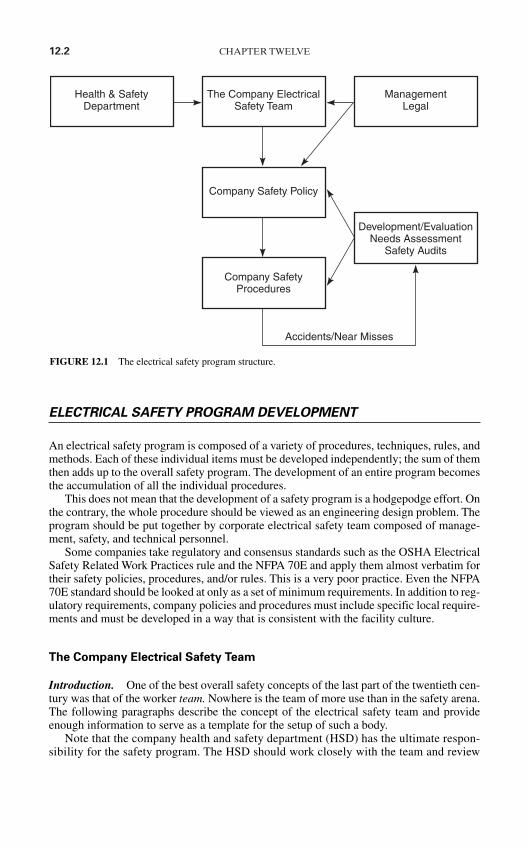
12.2 CHAPTER TWELVE
ELECTRICAL SAFETY PROGRAM DEVELOPMENT
An electrical safety program is composed of a variety of procedures, techniques, rules, andmethods. Each of these individual items must be developed independently; the sum of themthen adds up to the overall safety program. The development of an entire program becomesthe accumulation of all the individual procedures.
This does not mean that the development of a safety program is a hodgepodge effort. Onthe contrary, the whole procedure should be viewed as an engineering design problem. Theprogram should be put together by corporate electrical safety team composed of manage-ment, safety, and technical personnel.
Some companies take regulatory and consensus standards such as the OSHA ElectricalSafety Related Work Practices rule and the NFPA 70E and apply them almost verbatim fortheir safety policies, procedures, and/or rules. This is a very poor practice. Even the NFPA70E standard should be looked at only as a set of minimum requirements. In addition to reg-ulatory requirements, company policies and procedures must include specific local require-ments and must be developed in a way that is consistent with the facility culture.
The Company Electrical Safety Team
Introduction. One of the best overall safety concepts of the last part of the twentieth cen-tury was that of the worker team. Nowhere is the team of more use than in the safety arena.The following paragraphs describe the concept of the electrical safety team and provideenough information to serve as a template for the setup of such a body.
Note that the company health and safety department (HSD) has the ultimate respon-sibility for the safety program. The HSD should work closely with the team and review
Health & SafetyDepartment
The Company ElectricalSafety Team
ManagementLegal
Company Safety Policy
Company SafetyProcedures
Accidents/Near Misses
Development/EvaluationNeeds Assessment
Safety Audits
FIGURE 12.1 The electrical safety program structure.
all procedures and policies developed by the electrical safety team. As described in the fol-lowing, the HSD should have a representative on the team.
Structure. Generally, the safety team should include the following representatives/members:
Electrical workers An electrical worker should serve as the chairper-son of the team. In addition to the chairperson, sufficient members should be included from theworkforce to ensure that the workers have a signif-icant say in their overall safety program. Workingsupervisors should be eligible for these positions;however, supervision should never dominate theteam.
Health and safety professionals At least one health and safety professional shouldbe included on the team to advise and assist in theareas where his or her expertise apply.
Management A member of management should be present as anadvisor. This person can direct the team with respectto company policies to avoid the team conflictingwith company directives. The management repre-sentative should be as high a level as possible. Themanagement representative should always be will-ing to consider modification of conflicting companypolicies in the interest of improved safety.
Legal representation Company counsel should be represented on theteam; however, they should be there strictly in anadvisory capacity.
Responsibilities. The company electrical safety team (CEST) should have the followingresponsibilities and authorities:
The CEST should have overall responsibility for the development, implementation, eval-uation, and modification of the company electrical safety procedures. Either directly orthrough delegation, the CEST should develop the entire program, working closely withthe health and safety professionals.
The degree of authority vested in the CEST must be a matter of individual company pol-icy. Generally, the CEST should have the maximum authority allowable under existingcompany structure.
If the company has multiple locations, the CEST should appoint or sponsor elections foremployee electrical safety teams (EEST) at each site. The local teams will participate inlocal accident reviews, evaluate procedures, and determine the best way to apply themlocally, counsel employees, and implement and plan safety meetings.
The CEST should have representation at the management level for the purpose of partic-ipating in the development of the company safety policy.
Employee Electrical Safety Teams. Employee electrical safety teams should be put inplace to perform the actual fieldwork and legwork required by the CEST. The EEST willparticipate in accident investigation, program development, and any other activities deemed
SAFETY MANAGEMENT AND ORGANIZATIONAL STRUCTURE 12.3
12.4 CHAPTER TWELVE
necessary. Some companies appoint permanent employee electrical safety teams as part oftheir ongoing corporate structure.
Company Safety Policy
All safety programs should be underwritten by a company and/or departmental safety pol-icy. Although specific policy statements must vary from industry to industry, all policiesshould contain the following key statements:
1. The company is committed to safe work practices.
2. At a minimum, all company safety policies and procedures shall comply with applica-ble federal, state, and local standards as well as recognized consensus standards.
3. Safety is the premier consideration in performing work.
4. Employees will be required to follow all company safety procedures.
5. If a job cannot be safely done, it need not be done.
6. Each individual employee is uniquely responsible for his or her own personal safety.
7. The cooperation of all personnel will be required to sustain the safety program.
Assessing the Need
The development or revision of an electrical safety program should begin with an evalua-tion of any existing programs. This initial survey should closely examine and catalog thenumber and types of electrical accidents. Investigators should also be creative in their anal-ysis. That is, they should identify potential hazards as well as demonstrated ones.
One of the most effective ways to catalog safety hazards is to perform a safety audit.Safety audits are discussed later in this chapter.
Problems and Solutions
Based on the results of the needs assessment, accidents and potential problem areas shouldbe cataloged into cause categories. The specific categories selected should be chosen to fitthe industry. Good starting points are the seven categories used by the Occupational Safetyand Health Administration in the development of the Safety-Related Work Practices Rule.These categories, illustrated in Table 12.1, can be used for most electrical accidents. The
TABLE 12.1 Categories to Classify Accidents or Potential Accidents
1. Use of equipment or material too close to exposed energized linesa. Vehicles (e.g., cranes and dumptrucks)b. Other mechanical equipment (e.g., augers and derricks)c. Tools and materials (e.g., ladders and tree limbs)
2. Failure to use electrical protective equipment3. Assuming an unsafe position4. Failure to de-energize (and lockout-tagout) equipment5. Use of visibly defective electric equipment6. Blind reaching, drilling, digging, etc.7. No unsafe work practice or not enough information to classify
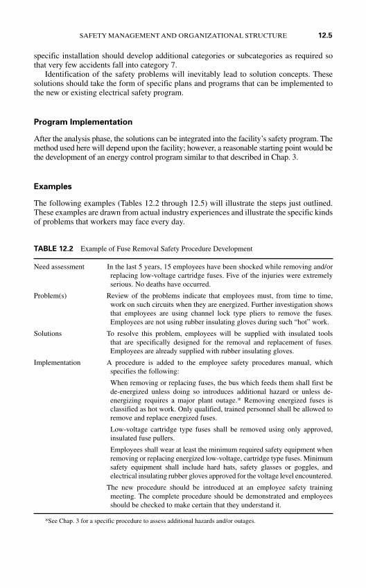
specific installation should develop additional categories or subcategories as required sothat very few accidents fall into category 7.
Identification of the safety problems will inevitably lead to solution concepts. Thesesolutions should take the form of specific plans and programs that can be implemented tothe new or existing electrical safety program.
Program Implementation
After the analysis phase, the solutions can be integrated into the facility’s safety program. Themethod used here will depend upon the facility; however, a reasonable starting point would bethe development of an energy control program similar to that described in Chap. 3.
Examples
The following examples (Tables 12.2 through 12.5) will illustrate the steps just outlined.These examples are drawn from actual industry experiences and illustrate the specific kindsof problems that workers may face every day.
SAFETY MANAGEMENT AND ORGANIZATIONAL STRUCTURE 12.5
TABLE 12.2 Example of Fuse Removal Safety Procedure Development
Need assessment In the last 5 years, 15 employees have been shocked while removing and/orreplacing low-voltage cartridge fuses. Five of the injuries were extremelyserious. No deaths have occurred.
Problem(s) Review of the problems indicate that employees must, from time to time,work on such circuits when they are energized. Further investigation showsthat employees are using channel lock type pliers to remove the fuses.Employees are not using rubber insulating gloves during such “hot” work.
Solutions To resolve this problem, employees will be supplied with insulated toolsthat are specifically designed for the removal and replacement of fuses.Employees are already supplied with rubber insulating gloves.
Implementation A procedure is added to the employee safety procedures manual, whichspecifies the following:
When removing or replacing fuses, the bus which feeds them shall first bede-energized unless doing so introduces additional hazard or unless de-energizing requires a major plant outage.* Removing energized fuses isclassified as hot work. Only qualified, trained personnel shall be allowed toremove and replace energized fuses.
Low-voltage cartridge type fuses shall be removed using only approved,insulated fuse pullers.
Employees shall wear at least the minimum required safety equipment whenremoving or replacing energized low-voltage, cartridge type fuses. Minimumsafety equipment shall include hard hats, safety glasses or goggles, andelectrical insulating rubber gloves approved for the voltage level encountered.
The new procedure should be introduced at an employee safety trainingmeeting. The complete procedure should be demonstrated and employeesshould be checked to make certain that they understand it.
*See Chap. 3 for a specific procedure to assess additional hazards and/or outages.
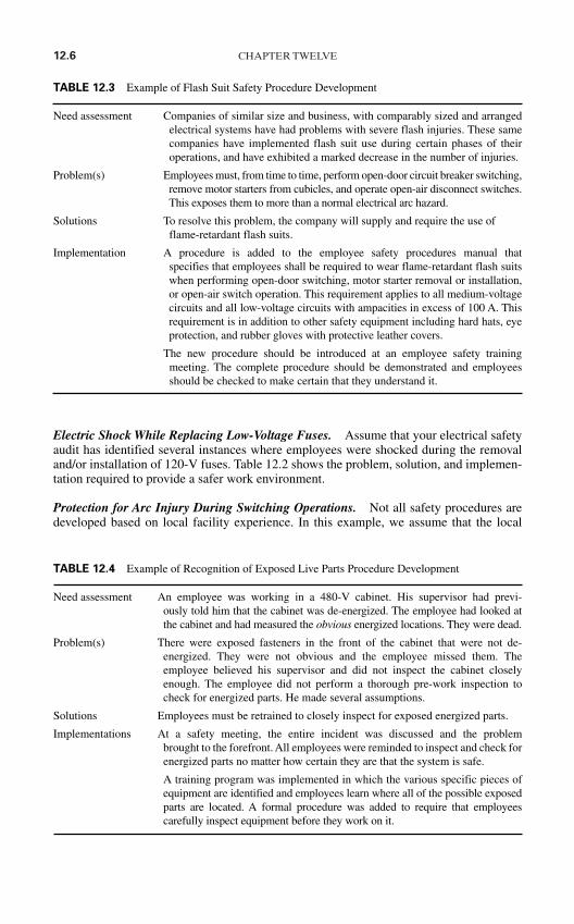
12.6 CHAPTER TWELVE
Electric Shock While Replacing Low-Voltage Fuses. Assume that your electrical safetyaudit has identified several instances where employees were shocked during the removaland/or installation of 120-V fuses. Table 12.2 shows the problem, solution, and implemen-tation required to provide a safer work environment.
Protection for Arc Injury During Switching Operations. Not all safety procedures aredeveloped based on local facility experience. In this example, we assume that the local
TABLE 12.3 Example of Flash Suit Safety Procedure Development
Need assessment Companies of similar size and business, with comparably sized and arrangedelectrical systems have had problems with severe flash injuries. These samecompanies have implemented flash suit use during certain phases of theiroperations, and have exhibited a marked decrease in the number of injuries.
Problem(s) Employees must, from time to time, perform open-door circuit breaker switching,remove motor starters from cubicles, and operate open-air disconnect switches.This exposes them to more than a normal electrical arc hazard.
Solutions To resolve this problem, the company will supply and require the use offlame-retardant flash suits.
Implementation A procedure is added to the employee safety procedures manual that specifies that employees shall be required to wear flame-retardant flash suitswhen performing open-door switching, motor starter removal or installation,or open-air switch operation. This requirement applies to all medium-voltagecircuits and all low-voltage circuits with ampacities in excess of 100 A. Thisrequirement is in addition to other safety equipment including hard hats, eyeprotection, and rubber gloves with protective leather covers.
The new procedure should be introduced at an employee safety trainingmeeting. The complete procedure should be demonstrated and employeesshould be checked to make certain that they understand it.
TABLE 12.4 Example of Recognition of Exposed Live Parts Procedure Development
Need assessment An employee was working in a 480-V cabinet. His supervisor had previ-ously told him that the cabinet was de-energized. The employee had looked atthe cabinet and had measured the obvious energized locations. They were dead.
Problem(s) There were exposed fasteners in the front of the cabinet that were not de- energized. They were not obvious and the employee missed them. Theemployee believed his supervisor and did not inspect the cabinet closelyenough. The employee did not perform a thorough pre-work inspection tocheck for energized parts. He made several assumptions.
Solutions Employees must be retrained to closely inspect for exposed energized parts.
Implementations At a safety meeting, the entire incident was discussed and the problem brought to the forefront. All employees were reminded to inspect and check forenergized parts no matter how certain they are that the system is safe.
A training program was implemented in which the various specific pieces ofequipment are identified and employees learn where all of the possible exposedparts are located. A formal procedure was added to require that employeescarefully inspect equipment before they work on it.
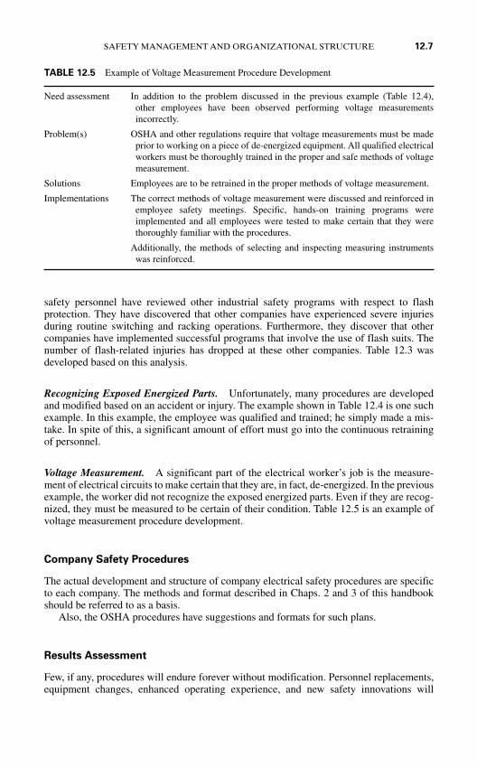
safety personnel have reviewed other industrial safety programs with respect to flashprotection. They have discovered that other companies have experienced severe injuriesduring routine switching and racking operations. Furthermore, they discover that othercompanies have implemented successful programs that involve the use of flash suits. Thenumber of flash-related injuries has dropped at these other companies. Table 12.3 wasdeveloped based on this analysis.
Recognizing Exposed Energized Parts. Unfortunately, many procedures are developedand modified based on an accident or injury. The example shown in Table 12.4 is one suchexample. In this example, the employee was qualified and trained; he simply made a mis-take. In spite of this, a significant amount of effort must go into the continuous retrainingof personnel.
Voltage Measurement. A significant part of the electrical worker’s job is the measure-ment of electrical circuits to make certain that they are, in fact, de-energized. In the previousexample, the worker did not recognize the exposed energized parts. Even if they are recog-nized, they must be measured to be certain of their condition. Table 12.5 is an example ofvoltage measurement procedure development.
Company Safety Procedures
The actual development and structure of company electrical safety procedures are specificto each company. The methods and format described in Chaps. 2 and 3 of this handbookshould be referred to as a basis.
Also, the OSHA procedures have suggestions and formats for such plans.
Results Assessment
Few, if any, procedures will endure forever without modification. Personnel replacements,equipment changes, enhanced operating experience, and new safety innovations will
SAFETY MANAGEMENT AND ORGANIZATIONAL STRUCTURE 12.7
TABLE 12.5 Example of Voltage Measurement Procedure Development
Need assessment In addition to the problem discussed in the previous example (Table 12.4),other employees have been observed performing voltage measurementsincorrectly.
Problem(s) OSHA and other regulations require that voltage measurements must be made prior to working on a piece of de-energized equipment. All qualified electricalworkers must be thoroughly trained in the proper and safe methods of voltagemeasurement.
Solutions Employees are to be retrained in the proper methods of voltage measurement.
Implementations The correct methods of voltage measurement were discussed and reinforced inemployee safety meetings. Specific, hands-on training programs wereimplemented and all employees were tested to make certain that they werethoroughly familiar with the procedures.
Additionally, the methods of selecting and inspecting measuring instrumentswas reinforced.
12.8 CHAPTER TWELVE
require that any safety program be periodically reviewed and updated. The following crite-ria should be used to evaluate the need to revise an existing safety procedure:
1. Accidents and near misses
2. Employee suggestions
3. Employee electrical safety committee recommendations (see next section)
4. Changes in regulatory or conseusus standards
EMPLOYEE ELECTRICAL SAFETY TEAMS
Reason
Electrical safety programs that are developed and/or administered without employee inputwill be ineffective. Employees know their jobs better than anyone. They understand thoseprocedures with which they are comfortable and those which seem wrong. An electricalsafety program that is developed without complete employee involvement has very littlechance of success.
Method
Employee safety teams provide the best method for ensuring employee participation in asafety program. Such teams should be composed of a minimum of three employees chosenby their peers. The team should have regularly scheduled meetings on a monthly basis—more often if required by accidents or emergency conditions. The meetings should be heldon company time.
Employee safety teams should be intimately involved with the entire safety program frominitial design to ongoing results evaluations. They should be officially sanctioned by man-agement and should have direct access to executive management. A limited, but useful, travelbudget should be made available to the team to allow them to attend seminars and visit otherfacilities to study other safety programs. Although the specific responsibilities of such a teammay vary from one company to another, the following may be used as guidelines.
Safety Program Development. Because of their familiarity with their jobs, employees arein a unique position to evaluate safety needs. What appears to be a perfectly safe procedureto a layperson may be obviously unsafe to a skilled, qualified worker. Furthermore, employ-ees will often talk to their peers more freely than to supervisors or management.
An employee safety team will be able to identify problems and solutions that outsidersmight miss. Because of this, the safety team should be directly involved with the safety pro-gram development and/or modification described earlier in this chapter.
Safety Meetings. Employees should control all or at least part of their safety meetings.Legislative or regulatory requirements should be scheduled by management and safety per-sonnel; however, other safety-related presentations should be generated by employees andadministrated through the employee safety team.
Accident Investigation. The team should be involved in the investigation of accidents.The best way to ensure this involvement is to have the employee safety team appoint amember to serve on the accident investigation team. Accident investigation is a very
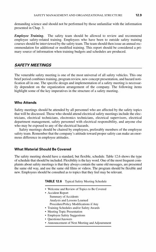
demanding science and should not be performed by those unfamiliar with the informationpresented in Chap. 3.
Employee Training. The safety team should be allowed to review and recommendemployee safety-related training. Employees who have been to outside safety trainingcourses should be interviewed by the safety team. The team should then issue an annual rec-ommendation for additional or modified training. This report should be considered a pri-mary source of information when training budgets and schedules are produced.
SAFETY MEETINGS
The venerable safety meeting is one of the most universal of all safety vehicles. This onebrief period combines training, program review, new concept presentation, and hazard noti-fication all in one. The specific design and implementation of a safety meeting is necessar-ily dependent on the organization arrangement of the company. The following itemshighlight some of the key imperatives in the structure of a safety meeting.
Who Attends
Safety meetings should be attended by all personnel who are affected by the safety topicsthat will be discussed. Those who should attend electrical safety meetings include the elec-tricians, electrical technicians, electronics technicians, electrical supervisors, electricaldepartment management, safety personnel with electrical responsibility, and anyone elsewho may be exposed to any of the electrical hazards.
Safety meetings should be chaired by employees, preferably members of the employeesafety team. Remember that the company’s attitude toward proper safety can make an enor-mous difference in employee attitudes.
What Material Should Be Covered
The safety meeting should have a standard, but flexible, schedule. Table 12.6 shows the typeof schedule that should be included. Flexibility is the key word. One of the most frequent com-plaints about safety meetings is that they always contain the same old messages, are presentedthe same old way, and use the same old films or videos. The program should be flexible andnew. Employees should be consulted as to topics that they feel may be relevant.
SAFETY MANAGEMENT AND ORGANIZATIONAL STRUCTURE 12.9
TABLE 12.6 Typical Safety Meeting Schedule
• Welcome and Review of Topics to Be Covered• Accident Report
Summary of AccidentsAnalysis and Lessons LearnedProcedure/Policy Modifications if Any
• Training Schedules and/or Safety Awards• Meeting Topic Presentation• Employee Safety Suggestions• Questions/Answers• Announcement of Next Meeting and Adjournment
12.10 CHAPTER TWELVE
Avoid using the safety meeting time for non–safety-related information. General com-pany announcements should be made at general employee meetings, not at safety meetings.
Also remember that employees who are injured at home cannot report to work. Safetymeetings should also address home safety issues. Topics such as safe use of appliances,house wiring safety, home lightning protection, and first aid can be useful to employeesboth on and off the job.
When Meetings Should Be Held
To accommodate work schedules, many companies hold their safety meetings at the begin-ning of the work day. Others may wait until the end of the day. Try moving the time of themeetings around. When the results of the meeting are evaluated, as described later, the mostappropriate time will be that in which the greatest amount of information is imparted.
For real variety, some companies have found that continually moving the meeting timesis effective. Some companies even hold meetings at night and invite spouses to attend. Thisapproach allows the whole family to become involved in safety and allows the employer topresent home safety topics more effectively.
Safety meetings should only be canceled when absolutely no other option is available.Major operational emergencies such as fires and major outages are the only acceptable rea-sons for canceling a safety meeting.
Where Meetings Should Be Held
Variety should also be exploited when choosing meeting locations. Most meetings will beheld at the work site for economic reasons; however, some meeting topics might call for dif-ferent locations. For example, a demonstration of the proper use of hot sticks might best beheld at a substation area, while tool safety training might be most effective if presented inthe shop. Remember that when demonstrations are given, even more extreme safety pre-cautions should be taken.
Evening safety meetings can be held at private banquet rooms or restaurants with meet-ing facilities. The meeting can be integrated with a social occasion that will allow manage-ment personnel, safety personnel, employees, and families to discuss problems and sharesolutions on a more informal basis. When such meetings are held, they should remain seri-ous, with safety as the premier topic.
How Long Meetings Should Be
Meetings held at the workplace should be kept to a maximum of 1 hour unless some spe-cial topic or presentation requires more time. Remember that a safety meeting is a trainingpresentation. Adult training sessions are best kept to short segments. Thus, if a meetingrequires more than the 1 hour time period, be certain that breaks are given every 45 min-utes or so. Evening meetings may be somewhat longer if a dinner or other social event isintegrated with the meeting.
Evaluation of Safety Meetings
Like all parts of a safety program, meetings should be constantly evaluated. Employee ques-tionnaires and quizzes should be used to evaluate the quality of the meetings and the amount
of information retained. These evaluations can be done on an anonymous basis so that employ-ees feel free to share negative as well as positive comments. When tests or questionnaires iden-tify problem areas, the meeting structure should be modified to correct the problem.
Follow-through. The safety program will not work if the company is not truly commit-ted. When safety suggestions are made, the company should follow through and report backto the employee in writing. The employee safety committee should monitor suggestionsand intervene if the company is not following through properly.
OUTAGE REPORTS
Safety hazards and electrical outages are frequently related to each other. Knowledge of thedetails that surround an electrical outage can be invaluable in pinpointing safety hazards.Outage reports can be used to
1. Target potential or existing safety hazards
2. Justify maintenance or additions to a power system to increase reliability
3. Gather data for designing better power systems or additions to other plants or facilities
Outage reports should include
Time and length of outage Cause of outage if known Results of outage (costs, injuries, etc.) Suggestions to present such an outage in the future.
SAFETY AUDITS
Description
Depending on the intended extent, audits vary from short, simple inspections of specificproblems or areas to large, companywide reviews that explore every facet of a safety pro-gram. Whatever their size or complexity, a safety audit is performed to review and assessthe ongoing safety elements of a business. Audits are designed to identify the weaknessesand strengths of a safety program.
Process. A comprehensive audit starts with a review of upper-management safety aware-ness and attitudes and continues through the entire organization. During the procedure, everyfacet of the safety program is reviewed, cataloged, critiqued, and—if necessary—modified.
Attitudes. The attitudes of company personnel can make or break the effectiveness of asafety audit. Many employees tend to take safety audits very personally. A properly runsafety audit should not be performed as an inquisition. Honest errors should be noted andcorrected without hostile indictments or defensive recriminations. All personnel should beaware that a safety audit is only one tool used to make the workplace safer for everyone.
Audits Versus Inspections. Some references differentiate between an audit and an inspec-tion. In such references, audits are portrayed as major, comprehensive efforts that include
SAFETY MANAGEMENT AND ORGANIZATIONAL STRUCTURE 12.11
12.12 CHAPTER TWELVE
all facets of the safety program. Inspections, on the other hand, are smaller, more conciseefforts that may assess only one small area or procedure.
While there may be some psychological advantage in separating the two terms, remem-ber that both are intended to identify, and subsequently eliminate, existing or potentialsafety hazards.
Purposes
The single most important purpose of a safety audit is to identify and eliminate safety haz-ards. There are, however, additional side benefits and purposes that are realized including
1. Employee morale is improved as safety problems are eliminated.
2. Audits provide a dynamic record of safety performance.
3. A positive cycle of safety improvement is created. That is, departments that get goodscores tend to work harder to maintain their high scores. Departments that do not do aswell tend to work harder to improve for the next audit.
4. Managers at all levels are made aware of many safety problems and procedures that theymight not otherwise discover. For example, an audit that includes analysis of OSHAcompliance may make managers aware of OSHA rules that were previously unknown.
5. When performed as a “family” procedure, a safety audit can actually enhance employer-employee relations. Employees respect management teams who truly put employeesafety first.
Procedure
The safety audit should review and evaluate each element of the safety procedure. Site-inspection trips, personnel interviews, task observation, and documentation review areamong the methods that may be used. Each portion of the company that is reviewed willhave its own specific concerns. Note that the items presented in the following sections areintended for example only. Specific facilities may require more or different audit criteria.
Facilities. Checkpoints for the electrical physical plant include the following:
1. Is the electric equipment kept clean?
2. Are safety exits clearly marked and unblocked by wire reels, ladders, and other suchequipment?
3. Are relay flags and other such indicators kept reset?
4. Is explosion-proof equipment properly maintained and sealed?
5. Are all electrical grounds in place and secure?
Employees. Properly trained, alert employees are at the heart of any safety program. Anindividual employee is always the person most responsible for his or her own personalsafety. The following points are typical of the types of checks that should be made to auditthe safety awareness of individual employees.
1. Are employees adequately trained?
2. Are employees familiar with their safety handbook?
3. Do employees know where all electrical safety equipment is located?
4. Can employees successfully perform safety-related procedures such as safety ground-ing and voltage measurement?
5. Are personnel familiar with the electrical safety one-line diagram?
6. Are employees familiar with the safety techniques that are unique to the various voltagelevels to which they will be exposed?
Management. Good safety practice starts at the top. If management includes itself in theaudit process, employees will accept that they too must be reviewed. Management involve-ment is more than just window dressing, however. Other management audit points includethe following:
1. Does the facility have a formal, written safety policy?
2. Are safety rules enforced uniformly?
3. Is there an employee safety committee to which management defers when technical andday-to-day decisions must be made?
4. Does management promote both on-the-job and off-the-job safety?
5. Does management provide, at company expense, CPR and other such training?
Safety Equipment. Various rules and regulations require the use of approved electrical safetyequipment. The following points are typical of safety equipment checks during an audit.
1. Is safety equipment readily available for all personnel?
2. Have all rubber goods been tested within the required period?
3. Are meters and instruments mechanically sound and electrically operable?
4. Are test equipment fuses properly sized?
5. Are safety interlocks operational and not bypassed?
6. Are safety signs, tags, warning tapes, and other such warning devices readily availableto all employees?
Safety Procedures. Energy control and other such safety procedures must be properlydeveloped and implemented. A few of the key points for procedures include
1. Are written switching orders required for planned outages?
2. Is a written copy of the lockout-tagout procedure available to all personnel?
3. Are all employees trained in electrical safety grounding?
4. Are safety procedures followed for each and every operation or are they bypassed in theinterest of production?
Documentation. Safety electrical one-line diagrams and other such documents are toofrequently ignored and allowed to fall behind or remain inaccurate. The following keypoints should be checked for safety-related documentation:
1. Are the electrical portions of the company safety handbook up-to-date and consistentwith currently accepted safety practice?
2. Are copies of all safety standards and practices readily available to all personnel?
3. Is the safety electrical one-line diagram up to date, accurate, and legible?
4. Are accident reporting forms, test sheets, procedures, and other such operational aidsreadily available?
SAFETY MANAGEMENT AND ORGANIZATIONAL STRUCTURE 12.13
12.14 CHAPTER TWELVE
The Audit Team
Audit teams should be composed of safety personnel, management personnel, and employ-ees. Because of their familiarity with safety auditing techniques, safety personnel should,generally, be the team leaders. The audit and assessment tasks should be shared equally byall team members.
The number of team members will, of course, depend upon the size of the facility or facil-ities being audited. A minimum of three members is recommended even for very small facil-ities. This will allow representations for safety, management, and employees.
Some companies use the employee safety team to spearhead safety audits. The safetyteam assigns audit personnel, reviews audit results, and continues to follow up on changes.
Audit Tools
The principal tool of the safety audit is the audit form (Figs. 12.2 to 12.7). A form of thistype should be developed for every area involved in the audit. In addition to such forms,audit team members should be supplied with copies of safety procedures, standards, andother such documents. Team members can thus evaluate whether the procedures and stan-dards are being followed or not. Note that the management and employee questionnairescan be used for statistical analysis.
Follow-Up
Emergency or life-threatening problems should be corrected immediately. Problems thatare left uncorrected continue to put employees and equipment at risk. Moreover, majoraudits that find problems which are not corrected send very negative signals to employees.
Follow-up to correct a problem should occur within a very short time after the results ofthe audit. Major safety problems should be corrected immediately. Action on less seriousproblems should begin within 1 month of the audit.
When audit results call for additional employee training, major system modification, orother such long-term expenditures, management should develop the plan within 1 month.No one expects major expenditures to be performed on a short-term basis; however, safetyconsiderations must be met in a timely and effective manner.
The audit report should be written as soon as the audit is complete. The timetable for thecorrection of observed problems should be based on three criteria as follows:
1. How serious is the problem? If an accident caused by this problem would result invery severe injuries or high levels of damage, the problem should be corrected imme-diately. This criterion is the most important of the three, and it should outweigh anyother considerations.
2. What is the likelihood that an accident will occur as a result of the problem noted in theaudit? If there is little possibility of an accident, correction of the problem may be rele-gated to a lower status.
3. How much will it cost to fix the problem?
Internal Versus External Audits
Although companies usually employ their own personnel in the performance of a safetyaudit, sometimes an external firm may be used. Each approach has its own advantages and

SAFETY MANAGEMENT AND ORGANIZATIONAL STRUCTURE 12.15
Outdoor Substations
Company
Location
Substation
Date Auditors
General Conditions
Item Comments
Properly fenced
Restricted access
Fence grounding
Rock and gravel (no vegetation)
Corrosion-free
Proper clearances
“Danger High Voltage” signs
Control room properly ventilated
Additional observations and comments:
FIGURE 12.2 Facilities audit form. (a) Outdoor substations; (b) indoor substation/electrical room; (c) mis-cellaneous outdoor equipment; (d) power transformers; (e) metal-clad switchgear; (f) Motor control centers;(g) battery stations; (h) panel boards. (Courtesy Cadick Corporation.)
Rat
ing
(a)

12.16 CHAPTER TWELVE
Indoor Substation/Electrical Room
Company
Location
Substation/Area
Date Auditors
General Conditions
Item Comments
Restricted access
“Danger High Voltage” signs
Improper material storage
Room properly ventilated
Proper clearances
Voltage level markings
General housekeeping
Corrosion-free
Fire extinguishers
Clear egress
Additional observations and comments:
FIGURE 12.2 (Continued)
Rat
ing
(b)

SAFETY MANAGEMENT AND ORGANIZATIONAL STRUCTURE 12.17
Miscellaneous Outdoor Equipment
Company
Location
Substation
Date Auditors
Item Comments
Lightning arresters
Air disconnect switches
Capacitor banks
Oil circuit breakers
Reclosers
Fused disconnects
CTs and PTs
Control transformers
Additional observations and comments:
FIGURE 12.2 (Continued)
Rat
ing
(c)

12.18 CHAPTER TWELVE
Power Transformers
Company
Location
Substation/Area Designation(s)
Date Auditors
Item Comments
Insulators
Gauges operable
Proper clearances
No signs of leaks
Equipment grounding
Grounding plates
Neutral ground resistors
Proper ventilation
Type of maintenance program
PCB stickers
Additional observations and comments:
FIGURE 12.2 (Continued)
Rat
ing
(d)

SAFETY MANAGEMENT AND ORGANIZATIONAL STRUCTURE 12.19
Metal-Clad Switchgear
Company
Location
Substation/Area Designation(s)
Date Auditors
Item Comments
Door and cover properly secured
Proper ventilation
Proper working space & clearances
Panel identification markings
Circuit identification markings
Voltage level markings
Protective device indicators
Type of maintenance program
Clear egress
Equipment grounding
Panel meters operative
Additional observations and comments:
FIGURE 12.2 (Continued)
Rat
ing
(e)

12.20 CHAPTER TWELVE
Motor Control Centers
Company
Location
Substation/Area Designation(s)
Date Auditors
Item Comments
Door and cover properly secured
Proper ventilation
Proper working space & clearances
Panel identification markings
Circuit identification markings
Voltage level markings
Indicators
Type of maintenance program
Clear egress
Equipment grounding
Panel meters operative
Additional observations and comments:
FIGURE 12.2 (Continued)
Rat
ing
(f)

SAFETY MANAGEMENT AND ORGANIZATIONAL STRUCTURE 12.21
Battery Stations
Company
Location
Substation/Area Designation(s)
Date Auditors
Item Comments
Restricted access
Proper ventilation
Eyewash station
Neutralizing solution
Proper working space & clearances
Electrolyte level
Signs of out-gassing
Voltage level markings
Corrosion-free
Type of maintenance program
Clear egress
Equipment grounding
Availability of battery PPE
Battery charger
Additional observations and comments:
FIGURE 12.2 (Continued)
Rat
ing
(g)

12.22 CHAPTER TWELVE
Panel Boards
Company
Location
Substation/Area Designation(s)
Date Auditors
Item Comments
Door and cover properly secured
Proper ventilation
Proper working space & clearances
Panel identification markings
Circuit identification markings
Voltage level markings
Type of maintenance program
Equipment grounding
Additional observations and comments:
FIGURE 12.2 (Continued)
Rat
ing
(h)
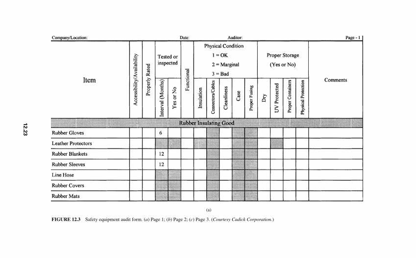
(a)
FIGURE 12.3 Safety equipment audit form. (a) Page 1; (b) Page 2; (c) Page 3. (Courtesy Cadick Corporation.)
12.2
3
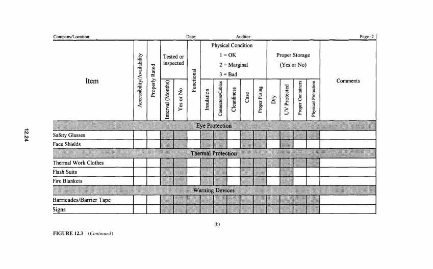
FIGURE 12.3 (Continued)
(b)
12.2
4
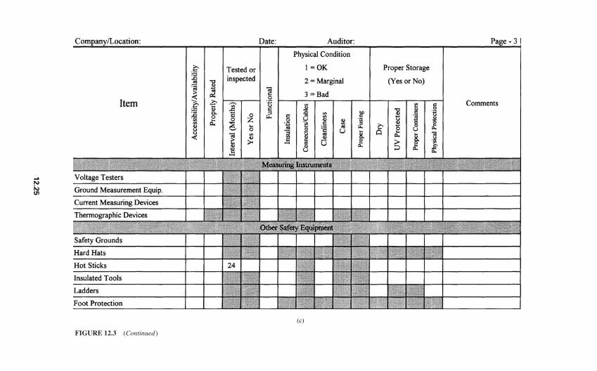
FIGURE 12.3 (Continued)
(c)
12.2
5
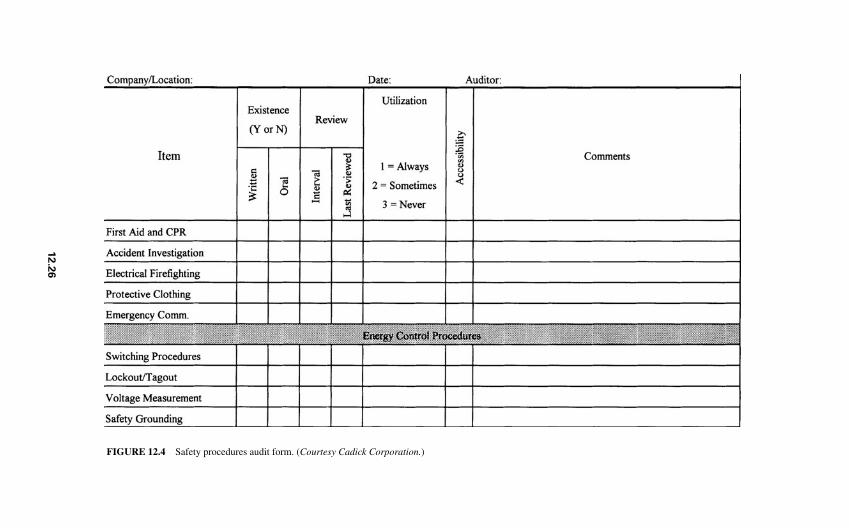
FIGURE 12.4 Safety procedures audit form. (Courtesy Cadick Corporation.)
12.2
6
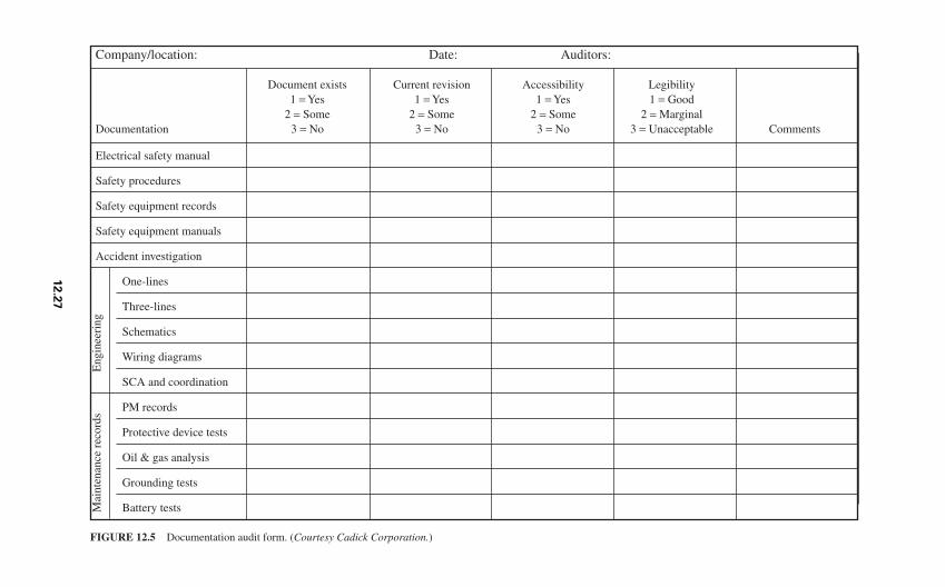
Company/location: Date: Auditors:
Document exists Current revision Accessibility Legibility1 = Yes 1 = Yes 1 = Yes 1 = Good
2 = Some 2 = Some 2 = Some 2 = MarginalDocumentation 3 = No 3 = No 3 = No 3 = Unacceptable Comments
Electrical safety manual
Safety procedures
Safety equipment records
Safety equipment manuals
Accident investigation
One-lines
Three-lines
Schematics
Wiring diagrams
SCA and coordination
PM records
Protective device tests
Oil & gas analysis
Grounding tests
Battery tests
FIGURE 12.5 Documentation audit form. (Courtesy Cadick Corporation.)
Mai
nten
ance
rec
ords
Eng
inee
ring
12.2
7
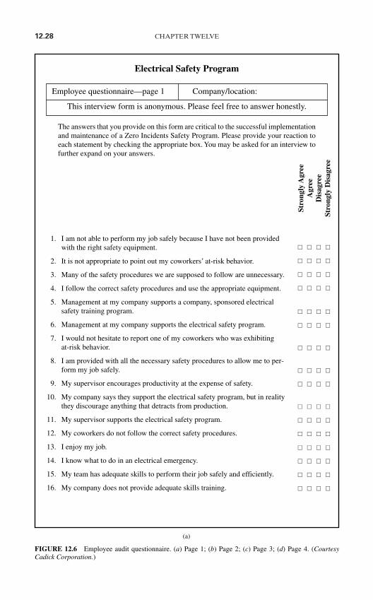
12.28 CHAPTER TWELVE
Electrical Safety Program
The answers that you provide on this form are critical to the successful implementationand maintenance of a Zero Incidents Safety Program. Please provide your reaction toeach statement by checking the appropriate box. You may be asked for an interview tofurther expand on your answers.
1. I am not able to perform my job safely because I have not been providedwith the right safety equipment.
2. It is not appropriate to point out my coworkers’ at-risk behavior.
3. Many of the safety procedures we are supposed to follow are unnecessary.
4. I follow the correct safety procedures and use the appropriate equipment.
5. Management at my company supports a company, sponsored electricalsafety training program.
6. Management at my company supports the electrical safety program.
7. I would not hesitate to report one of my coworkers who was exhibiting at-risk behavior.
8. I am provided with all the necessary safety procedures to allow me to per-form my job safely.
9. My supervisor encourages productivity at the expense of safety.
10. My company says they support the electrical safety program, but in realitythey discourage anything that detracts from production.
11. My supervisor supports the electrical safety program.
12. My coworkers do not follow the correct safety procedures.
13. I enjoy my job.
14. I know what to do in an electrical emergency.
15. My team has adequate skills to perform their job safely and efficiently.
16. My company does not provide adequate skills training.
FIGURE 12.6 Employee audit questionnaire. (a) Page 1; (b) Page 2; (c) Page 3; (d) Page 4. (CourtesyCadick Corporation.)
Employee questionnaire—page 1 Company/location:
This interview form is anonymous. Please feel free to answer honestly.
Stro
ngly
Agr
eeA
gree
Dis
agre
eSt
rong
ly D
isag
ree
(a)
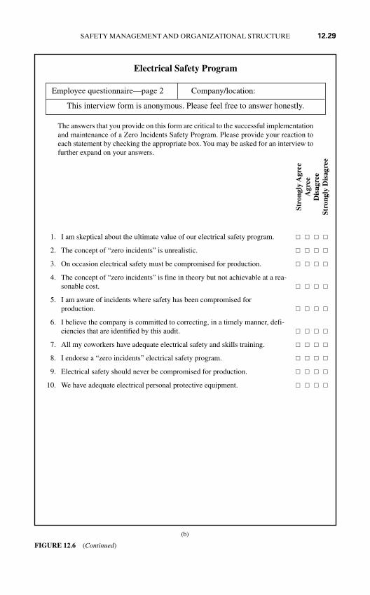
SAFETY MANAGEMENT AND ORGANIZATIONAL STRUCTURE 12.29
Electrical Safety Program
The answers that you provide on this form are critical to the successful implementationand maintenance of a Zero Incidents Safety Program. Please provide your reaction toeach statement by checking the appropriate box. You may be asked for an interview tofurther expand on your answers.
1. I am skeptical about the ultimate value of our electrical safety program.
2. The concept of “zero incidents” is unrealistic.
3. On occasion electrical safety must be compromised for production.
4. The concept of “zero incidents” is fine in theory but not achievable at a rea-sonable cost.
5. I am aware of incidents where safety has been compromised for production.
6. I believe the company is committed to correcting, in a timely manner, defi-ciencies that are identified by this audit.
7. All my coworkers have adequate electrical safety and skills training.
8. I endorse a “zero incidents” electrical safety program.
9. Electrical safety should never be compromised for production.
10. We have adequate electrical personal protective equipment.
FIGURE 12.6 (Continued)
Employee questionnaire—page 2 Company/location:
This interview form is anonymous. Please feel free to answer honestly.
Stro
ngly
Agr
eeA
gree
Dis
agre
eSt
rong
ly D
isag
ree
(b)
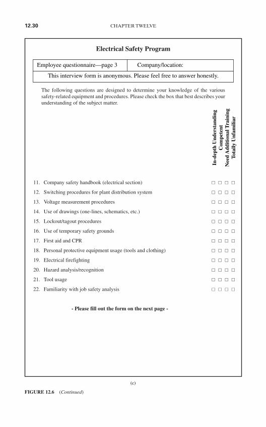
12.30 CHAPTER TWELVE
Electrical Safety Program
The following questions are designed to determine your knowledge of the varioussafety-related equipment and procedures. Please check the box that best describes yourunderstanding of the subject matter.
11. Company safety handbook (electrical section)
12. Switching procedures for plant distribution system
13. Voltage measurement procedures
14. Use of drawings (one-lines, schematics, etc.)
15. Lockout/tagout procedures
16. Use of temporary safety grounds
17. First aid and CPR
18. Personal protective equipment usage (tools and clothing)
19. Electrical firefighting
20. Hazard analysis/recognition
21. Tool usage
22. Familiarity with job safety analysis
- Please fill out the form on the next page -
FIGURE 12.6 (Continued)
Employee questionnaire—page 3 Company/location:
This interview form is anonymous. Please feel free to answer honestly.
In-d
epth
Und
erst
andi
ngC
ompe
tent
Nee
d A
ddit
iona
l Tra
inin
gTo
tally
Unf
amili
ar
(c)
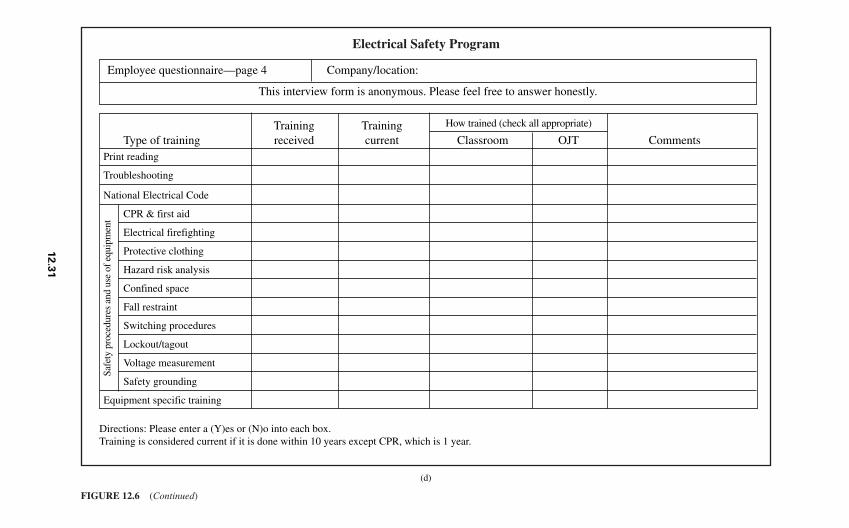
Electrical Safety Program
FIGURE 12.6 (Continued)
Employee questionnaire—page 4 Company/location:
This interview form is anonymous. Please feel free to answer honestly.
Training TrainingType of training received current Classroom OJT Comments
Print reading
Troubleshooting
National Electrical Code
CPR & first aid
Electrical firefighting
Protective clothing
Hazard risk analysis
Confined space
Fall restraint
Switching procedures
Lockout/tagout
Voltage measurement
Safety grounding
Equipment specific training
Safe
ty p
roce
dure
s an
d us
e of
equ
ipm
ent
How trained (check all appropriate)
Directions: Please enter a (Y)es or (N)o into each box.Training is considered current if it is done within 10 years except CPR, which is 1 year.
(d)
12.3
1
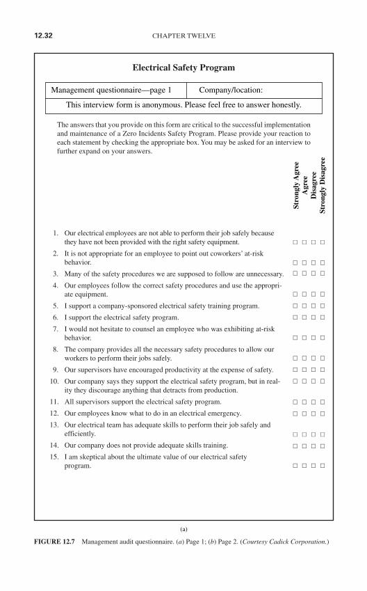
12.32 CHAPTER TWELVE
Electrical Safety Program
The answers that you provide on this form are critical to the successful implementationand maintenance of a Zero Incidents Safety Program. Please provide your reaction toeach statement by checking the appropriate box. You may be asked for an interview tofurther expand on your answers.
1. Our electrical employees are not able to perform their job safely becausethey have not been provided with the right safety equipment.
2. It is not appropriate for an employee to point out coworkers’ at-riskbehavior.
3. Many of the safety procedures we are supposed to follow are unnecessary.
4. Our employees follow the correct safety procedures and use the appropri-ate equipment.
5. I support a company-sponsored electrical safety training program.
6. I support the electrical safety program.
7. I would not hesitate to counsel an employee who was exhibiting at-riskbehavior.
8. The company provides all the necessary safety procedures to allow ourworkers to perform their jobs safely.
9. Our supervisors have encouraged productivity at the expense of safety.
10. Our company says they support the electrical safety program, but in real-ity they discourage anything that detracts from production.
11. All supervisors support the electrical safety program.
12. Our employees know what to do in an electrical emergency.
13. Our electrical team has adequate skills to perform their job safely andefficiently.
14. Our company does not provide adequate skills training.
15. I am skeptical about the ultimate value of our electrical safety program.
FIGURE 12.7 Management audit questionnaire. (a) Page 1; (b) Page 2. (Courtesy Cadick Corporation.)
Management questionnaire—page 1 Company/location:
This interview form is anonymous. Please feel free to answer honestly.
Stro
ngly
Agr
eeA
gree
Dis
agre
eSt
rong
ly D
isag
ree
(a)

SAFETY MANAGEMENT AND ORGANIZATIONAL STRUCTURE 12.33
Electrical Safety Program
The answers that you provide on this form are critical to the successful implementationand maintenance of a Zero Incidents Safety Program. Please provide your reaction toeach statement by checking the appropriate box. You may be asked for an interview tofurther expand on your answers.
16. The concept of “zero incidents” is unrealistic.
17. On occasion electrical safety must be compromised for production.
18. The concept of “zero incidents” is fine in theory but not achievable at a reasonable cost.
19. I am aware of incidents where safety has been compromised forproduction.
20. I am committed to correcting, in a timely manner, deficiencies that areidentified by this audit.
21. All of my employees have adequate electrical safety and skills training.
22. I endorse a “zero incidents” electrical safety program.
23. Electrical safety should never be compromised for production.
24. All of my employees have adequate electrical personal protective equip-ment.
FIGURE 12.7 (Continued)
Management questionnaire—page 2 Company/location:
This interview form is anonymous. Please feel free to answer honestly.
Stro
ngly
Agr
eeA
gree
Dis
agre
eSt
rong
ly D
isag
ree
(b)

12.34 CHAPTER TWELVE
disadvantages. Three principal reasons may call for the use of an external consultant in theperformance of a safety audit:
1. Consultants perform such audits on a routine basis and, therefore, tend to be more effi-cient than inexperienced employees.
2. Consultants tend to be dispassionate and therefore more objective in their analysis.
3. In-house personnel may not be available because of work schedules.
Of course, the use of consultants has some disadvantages as well, such as the following:
1. Consultants lack familiarity with their clients’ in-house systems and conditions.
2. Employees may not speak as freely with an outsider as they do with their own coworkers.
CHAPTER 13SAFETY TRAINING
METHODS AND SYSTEMS
INTRODUCTION
“Here’s your rubber gloves. Go follow Joe.” For much of the second half of the twentiethcentury, this was the ultimate safety training method for many facilities. Fortunately, safetytraining professionals have managed to get two critical messages across:
1. Bad training is worse than no training at all.
2. Good training is both an art and a science.
This chapter defines “good” training and shows how it can augment a safety program. Theinformation can be used by employers and consultants alike. Consultants can use the infor-mation to help set up training programs for their clients. Employers can use the informationto evaluate training consultants and/or take preliminary steps to set up their own training pro-grams. Note: This information is applicable to all types of technical training. Refer to theAmerican Society of Training and Development (www.astd.org) for training details.
Safety Training Definitions
For the purposes in this chapter, training is defined as a formal process used to generate adesired positive change in the behavior of an individual or group of individuals. Notice theuse of the word “formal.” Training must be “on purpose.” Never allow training to just hap-pen. Organize it, develop objectives, and administer.
Training is not the same thing as education, although training may well include educa-tion. Education is used to add to the cognitive skills and abilities of an individual or indi-viduals. In other words, education teaches you how to think, while training modifies yourbehavior.
Behavioral modification is the core of training; however, there are many different typesof behavioral modification. Three examples follow.
1. Many training companies offer training courses wherein they attempt to teach gen-eral electrical safety procedures. While these courses are generally excellent, they do notdirectly address the specific procedures of each student’s company. Rather, the coursesemphasize the importance of good safety and show clients what should be done. The behav-ioral change that occurs is an increase in the safety effort. Such an increase will lead tomany benefits; however, the student will need additional safety training in his or her ownspecific job requirements.
13.1
Copyright © 2006 by The McGraw-Hill Companies, Inc. Click here for terms of use.
13.2 CHAPTER THIRTEEN
2. Many in-house training programs teach the safety aspects of the maintenance oroperation of a range of specific types of equipment. For example, a four-day program whichteaches the maintenance of low-voltage power circuit breakers will spend great amounts oftime discussing and showing the safety aspects of the particular equipment. This type ofbehavior modification is relatively specific in that it teaches detailed procedures for a classof equipment—low-voltage power circuit breakers. The desired behavior is the use ofproper safety techniques to ensure that students will safely maintain their breakers.
3. A manufacturer’s training program on a specific piece of equipment is a third exam-ple. When the manufacturer of an uninterruptible power supply (UPS) offers a course onthe operation and maintenance of their UPS system, very specific safety procedures aretaught. In this instance, the manufacturer knows that good maintenance and operation willresult in fewer problems. However, the manufacturer also knows that trained personnelmust perform the maintenance safely. Here, the desired modification is reduced to a rela-tively few, very specific procedures.
In each of the examples just given, the training programs should be prefaced with edu-cational objectives. An educational objective is a specific, measurable behavioral changerequired of the student. For example, in a lockout-tagout course, an objective might be asfollows: “The student is expected to determine that a given system has been de-energizedby correctly performing the three-step voltage-measurement process.” A complete list ofobjectives should precede every module in a training program. The use of objectives allowsthe trainer and the trainee to be measured accurately and objectively. All the training dis-cussed in this chapter will be objective-based training.
Training Myths
The electrical safety industry has at least two major training myths. These myths hurt or insome cases eliminate the implementation of good training programs.
Myth #1: My People Can Learn by Just “Doing Their Job.” This is the ultimate in “gofollow Joe” thinking. The fact is that today’s electrical systems are too complex to permitself-training unless it is very well organized and documented. The best result from such anapproach will be slow, very expensive learning curves. The more likely result will beemployees who learn improperly and make potentially grave errors.
Misconceptions are among the biggest problems for professional trainers. Adult learn-ers have substantially more trouble unlearning a concept than they do learning one. Whileexperience is definitely the best teacher, experience should be prefaced with a properlyorganized and presented training experience.
Of course, well-designed self-training programs are an excellent source of training. Thekey word here, however, is designed. Simply turning an employee loose with an instructionbook is not effective.
Myth #2: My Supervisors Can Train My People. Training is a part of every supervisor’sjob, but it should not be allowed to become the only part for three basic reasons. First, intoday’s highly regulated workplace, a supervisor has his or her hands full with the day-to-day requirements of supervising. They simply do not have the time to put in the detailedeffort required for good training. Second, good technical or supervision skills do not nec-essarily include good training skills. The ability to train well is an art. The third considera-tion is the “person with a briefcase” syndrome. Employees tend to listen closely and learnfrom a trainer from outside the company. The feeling is that this person brings a fresh view-point to the job. Frankly, this belief has some merit. The outside viewpoint can often instillskills and ideas that are not available from inside.
SAFETY TRAINING METHODS AND SYSTEMS 13.3
Conclusion
1. Insurance companies are increasing safety requirements for their insured companies.
2. The technology of power systems continues to spiral upward.
3. Systems grow at an ever increasing rate.
4. Regulatory requirements continue to increase in number and complexity.
All these facts demand that employees be trained. Good training is available from a varietyof sources.
ELEMENTS OF A GOOD TRAINING PROGRAM
If you do not know what it is made of, it is hard to build. Because of this fact, many com-panies, even with strong training commitment, have poor training programs. From a safetytraining standpoint, three types of training can be defined—classroom, on-the-job, andself-training. A complete adult training package must include all three of these methodsassembled in a formal, planned program. Each method has certain critical elements, someof them shared.
Classroom Training
Classrooms. When most of us think of classrooms, we think of the rooms where we wentto grade school . . . the small, cramped desks with books underneath the seat, chalk dust,and the spinsterly schoolmarm. Adult classrooms need to be designed for adults.
The classroom should be spacious but not huge. The students should not be crampedtogether and should have sufficient table or desk space to spread out their texts and othermaterials.
The classroom should be well lit and quiet. Dim lighting is more conducive to sleepingthan learning, and noise from a nearby production facility can completely destroy thelearning process.
The classroom should be as far from the students’ work area as possible. This serves twopurposes.
1. A remote location tends to focus the student on learning.2. Interruptions by well-meaning supervisors are minimized.
All required audiovisual equipment should be readily available. Screens should be posi-tioned for easy viewing and controls should be readily accessible to the instructor. Avoidusing a white board for a screen due to the glare.
Laboratories. The adult learner must learn by doing. For safety training, learning bydoing means laboratory sessions and/or on-the-job training. Many of the design featuresmentioned for classrooms also apply to laboratories. However, there are a few specialconsiderations.
1. Avoid using the same room for both laboratory and classroom. A room large enough forboth is usually too large for effective classroom presentation. Too small a room, on theother hand, crowds the students during lecture and laboratory. Equipment needed totrain students in procedures should be placed in positions where it does not interferewith the lecture presentation.
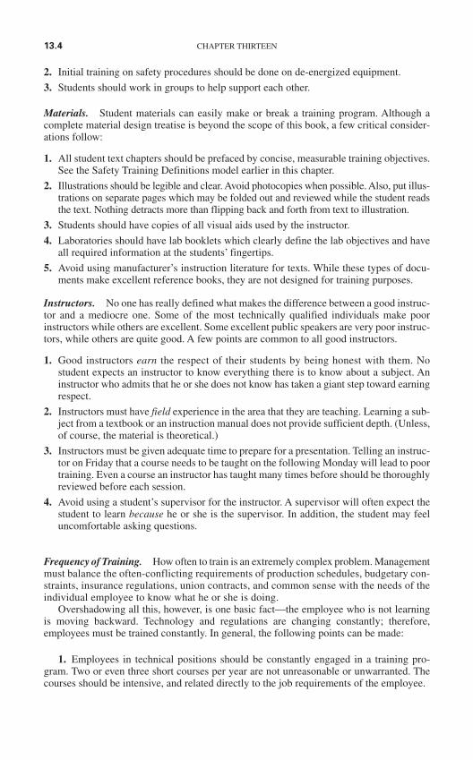
13.4 CHAPTER THIRTEEN
2. Initial training on safety procedures should be done on de-energized equipment.
3. Students should work in groups to help support each other.
Materials. Student materials can easily make or break a training program. Although acomplete material design treatise is beyond the scope of this book, a few critical consider-ations follow:
1. All student text chapters should be prefaced by concise, measurable training objectives.See the Safety Training Definitions model earlier in this chapter.
2. Illustrations should be legible and clear. Avoid photocopies when possible. Also, put illus-trations on separate pages which may be folded out and reviewed while the student readsthe text. Nothing detracts more than flipping back and forth from text to illustration.
3. Students should have copies of all visual aids used by the instructor.
4. Laboratories should have lab booklets which clearly define the lab objectives and haveall required information at the students’ fingertips.
5. Avoid using manufacturer’s instruction literature for texts. While these types of docu-ments make excellent reference books, they are not designed for training purposes.
Instructors. No one has really defined what makes the difference between a good instruc-tor and a mediocre one. Some of the most technically qualified individuals make poorinstructors while others are excellent. Some excellent public speakers are very poor instruc-tors, while others are quite good. A few points are common to all good instructors.
1. Good instructors earn the respect of their students by being honest with them. Nostudent expects an instructor to know everything there is to know about a subject. Aninstructor who admits that he or she does not know has taken a giant step toward earningrespect.
2. Instructors must have field experience in the area that they are teaching. Learning a sub-ject from a textbook or an instruction manual does not provide sufficient depth. (Unless,of course, the material is theoretical.)
3. Instructors must be given adequate time to prepare for a presentation. Telling an instruc-tor on Friday that a course needs to be taught on the following Monday will lead to poortraining. Even a course an instructor has taught many times before should be thoroughlyreviewed before each session.
4. Avoid using a student’s supervisor for the instructor. A supervisor will often expect thestudent to learn because he or she is the supervisor. In addition, the student may feeluncomfortable asking questions.
Frequency of Training. How often to train is an extremely complex problem. Managementmust balance the often-conflicting requirements of production schedules, budgetary con-straints, insurance regulations, union contracts, and common sense with the needs of theindividual employee to know what he or she is doing.
Overshadowing all this, however, is one basic fact—the employee who is not learningis moving backward. Technology and regulations are changing constantly; therefore,employees must be trained constantly. In general, the following points can be made:
1. Employees in technical positions should be constantly engaged in a training pro-gram. Two or even three short courses per year are not unreasonable or unwarranted. Thecourses should be intensive, and related directly to the job requirements of the employee.
SAFETY TRAINING METHODS AND SYSTEMS 13.5
2. Employee training should be scheduled strategically to occur before job requirements.In other words, an employee charged with cable testing during an outage should go to acable testing school a few weeks prior to the outage. Few of us can remember a complextechnical procedure for two or three years.
3. Training should be provided at least as often as required by regulatory requirements.Remember that standards and regulations only call out minimum requirements.
4. Regulatory requirements must be met. For example, OSHA rules require annualreview of lockout/tagout. Training is required if problems are noted.
On-the-Job Training (OJT)
On-the-job training will be discussed in great detail in a later section. As far as the elementsof laboratories, instructors, materials, and frequency of training are concerned, virtually allthe previous discussion applies with the following additions:
1. The laboratory for OJT is the whole plant or facility. The student learns while actuallyon the job.
2. In OJT, the supervisor is often the most logical choice for an instructor. In thisrole, however, the instructor does not usually get involved in a direct one-on-one trainingsession. Rather the instructor gives the student the objectives for each OJT session and thenevaluates progress.
3. Good training is done on purpose. A complete training program will have OJTmaterials which include objectives, reading materials, and examples of what is to be done.In addition the student should have a record card (see Fig. 13.1) (called a qual card in themilitary) which identifies each area of responsibility. When the student has performedsatisfactorily, the instructor checks off on the card to indicate successful completion.
FIGURE 13.1 A student qualification sheet.
13.6 CHAPTER THIRTEEN
4. Since employees are on the job every day, they are (theoretically) learning every day.This is not, however, true OJT. Remember that all good training is done on purpose.Typically a student should be given one specific OJT assignment at least once per week. Aninstructor (supervisor) should observe the successful completion of the assignment, and theemployee should be given credit for the job.
Self-training
Most well-intentioned self-training fails simply because it is not organized. An adult mustknow what is expected before he or she can perform. In this sense then, self-training hasmuch in common with OJT, and virtually all the comments which apply to OJT also applyto self-training.
The most important element of self-training is materials. The material for self-trainingmust be written very carefully. Small, self-supporting modules which are prefaced withclear objectives should serve as the core for self-training materials. Each module should beended with self-progress quizzes. After the student completes each module or related groupof modules, an examination should be administered by the instructor.
Conclusion
When confronted with requirements for training, such as those previously outlined, manycompanies are staggered by what appears to be a very expensive investment. The invest-ment made in training is returned many times over in improved safety, morale, and pro-ductivity. Furthermore, a training program that does not have the proper elements willprobably not be good training, and poor training is worse than no training at all.
ON-THE-JOB TRAINING
The major difference between 25 years of experience and 1 year of experience repeated25 times is OJT. Good, well-planned, on-purpose OJT is the heart and soul of an adult learn-ing program. Adults must learn by doing, and the workplace is the best laboratory. The threemajor segments of OJT include setup, implementation, and evaluation.
You must involve the employees in the development of this program. Their input andfeedback will be critical every step of the way. The employee safety committee can also beused as a training committee and should oversee every aspect of the training program devel-opment and presentation.
Note that safety topics are especially suitable for presentation in an OJT format. Thebest way to memorize critical safety procedures is while actually performing them underfield conditions. Note also, however, that special supervision must be made when personnelare learning safety procedures with energized equipment.
Setup
As noted previously, all training must be properly planned. Good training implies that it isbeing done on purpose. The setup portion is the most critical of all and must be properlyexecuted because it serves as the foundation.
Step 1. Define the employees’ job functions. This step (often called a job analysis) is crit-ical to all training but especially to OJT. Since OJT takes place while actually on the job,
SAFETY TRAINING METHODS AND SYSTEMS 13.7
you must know what your employees do before you can train them. This is a simple con-cept, but it is surprising how many organizations miss this step. The performance of the jobanalysis can be as simple as asking your employees to make a list of what they do. The anal-ysis of time sheets is another good approach. A final source of information is to ask yoursupervisors to list job functions for employees.
Notice that interviewing supervisors is the last of the three approaches. Unfortunately,company management and supervision are not always as closely in tune with day-to-dayemployee activities as they should be. This is not always true, but too often it is.
At the conclusion of this step, you should have a complete listing of the major jobs per-formed by your employees; for example, one major job is to remove motor starters frommotor control centers with energized buses.
To simplify this step, concentrate on major job functions. Detail can be added as the OJTprogram develops over the years.
Step 2. Isolate the job functions that are practical and measurable. For example, you mayhave one task such as troubleshooting the south plant UPS system. While troubleshootingis a trainable skill, it is very difficult to measure troubleshooting ability in an OJT environ-ment. The example given in the previous step (e.g., removal of starters from motor controlcenters) is measurable and practical. Initially only the practical and measurable skills shouldbe included in the OJT program. As your program’s sophistication increases, you may wishto add more cognitive skills.
As each job function is determined, it should be identified with a simple numbering sys-tem. For example, the starter removal might be job function number 1; cable testing, jobfunction number 2; and so on. This makes it possible to keep records of which job functionsemployees have received training in.
Step 3. Break each job function into tasks, subtasks, and detailed procedures. Using relaytesting as an example, we might develop several tasks including the de-energizing of thecubicle, proper use of safety equipment, mechanically removing the starter, and so forth.The safety subtasks would include the proper voltage measurement, inspection of rubbergloves, application of safety grounds, and so on. The detailed procedures can be developedeither in-house or from manufacturer’s literature.
Step 4. Develop training objectives for the tasks and subtasks. The objectives should havethe measurement criteria contained within them. The following examples use the motorstarter removal as its subject.
Task
1. The employee shall independently remove a low-voltage motor starter from its cubicle.The job shall be performed using all applicable company safety standards.
Subtasksa. The employee shall perform a safety inspection for a set of low-voltage rubber
gloves.b. The employee shall wear a flash suit, previously inspected rubber gloves, hard hat,
and face shield.c. The employee shall stop the motor and de-energize the starter module. He or she
shall demonstrate proper procedure and stand in a safe work location while per-forming these steps.
Here we have shown only one of the objectives; there would be several more, one for eachsafety task and one for the mechanical procedures.
13.8 CHAPTER THIRTEEN
Step 5. Develop the written materials necessary to support the program. The followingshould be developed as a minimum:
1. Complete set of written objectives.
2. Written, detailed description of each task. To accomplish this portion, manufacturer’sliterature may augment in-house–developed materials.
3. Diagrams, illustrations, or examples.
4. Employee record cards. The cards should have space for the employee’s name, classifi-cation, and other demographic data. The majority of the card should contain space forcompleted job functions (by identification code), time of completion, and supervisor’sinitials indicating successful completion.
Implementation
The implementation phase of an OJT program should be a simple extension of the setupphase.
Step 1. Select several of the job functions to be used as trial runs of the OJT program. Atthe same time, select an experienced group of employees to receive the initial training.Develop the record cards for each employee.
Step 2. Thoroughly indoctrinate each of the test employees in the program and give themadvance knowledge of what is expected. Of course, if you have been properly including theemployees in the development phase, this step will be unnecessary.
Step 3. Introduce the training one job function at a time. Scheduling should be made byworking the program into the normal work schedule. That is, when plant scheduling requiresrelay testing, use the opportunity to provide the OJT.
Step 4. Have the employee’s supervisor go over the task with the employee and make cer-tain the employee thoroughly understands what is required of him or her. Remember, thisis training and the supervisor is the instructor in this case. The employee should performthe work, with the instructor giving guidance. The supervisor should watch the employeein the task and make certain all tasks are performed to within measurement criteria.
Step 5. After each training session is completed, thoroughly evaluate the results. See thenext section for a more detailed description of evaluation.
Step 6. Gradually involve each existing and new employee in the OJT program. Anytimean employee is called upon to perform a new job function or task, the OJT program shouldbe implemented and the employee’s record card should be updated accordingly.
Evaluation
Step 1. The results each employee obtains should be measured against the criteria estab-lished during the setup phase. Do not make any assumptions based on just one or twoemployees. Poor performance by several employees could mean the program is bad, or itcould mean that more classroom training is required.
SAFETY TRAINING METHODS AND SYSTEMS 13.9
Step 2. Interview the employees in a confidential manner. Give them a chance to critiquethe entire training program. All aspects—materials, implementation, objectives—should bereviewed.
Step 3. Interview the supervisor to get his or her feedback.
Step 4. Based on the first three steps, modify the program as required.
Step 5. Every two years review the program from top to bottom.
Conclusion
One major misstep taken by many organizations when they enter the world of OJT is to forgetthe key word—training. On-the-job training is not an on-the-job test. Rather it is on-the-jobtraining. Remember that and do not forget to provide the necessary field instruction as theprogram progresses.
In general, OJT will not stand alone. It must be accompanied by good classroom instruc-tion and/or self-training properly implemented and monitored. As stated in the previoussection, OJT can be the most cost-effective of all the parts of a training program.
TRAINING CONSULTANTS AND VENDORS
Only very large companies can justify having their own, completely self-supporting,in-house training organizations. Even when in-house organizations exist, they frequentlyuse outside vendors for support and special programs. In other words, you should use train-ing consultants and vendors for the same reasons you use any consultant or vendor—whentime, personnel, expertise, or economics make it impossible to perform the task yourself.
Training consultants fall roughly into three categories—those who provide canned pro-grams, those who develop and present tailored programs, and those who provide traininganalysis. Of course, some companies fit into more than one of the categories.
Canned Programs and Materials
Programs. Companies which provide the short one-week, manufacturer’s type of semi-nars have proliferated since the early 1960s. Training programs are available in electricalsafety, circuit breaker maintenance, relay testing, uninterruptible power supplies, pro-grammable logic controllers, and a host of other such topics. Usually these courses are fromthree days to two weeks in duration. They are normally presented either in a training cen-ter or at a hotel with adequate meeting facilities. Some of them are equipment-specific,while others are generic in nature. Pricing varies, but these seminars generally offer a veryeconomical approach when you have only one or two employees to train.
Learning by mail programs, called correspondence schools, also fall into this generalcategory. Some companies have been providing programmed mail-order instruction fordecades. The correspondence schools are especially useful for vocational-type training at amore generic level.
The vocational technical schools (votechs), both private and public, fill yet anotherneed in this arena. Many companies are requiring two-year associate’s degrees or theequivalent for employment in certain technical areas. The votech schools provide such
13.10 CHAPTER THIRTEEN
programs. Most of the votechs have evening courses, thus allowing students to attend intheir free time.
Each of these three types of programs has its own advantages. The one-week seminar isvery intensive and provides training in very specialized areas in a hurry. The correspon-dence schools are very effective for students who have schedules that make attending classesdifficult. The votech types of programs are excellent for those students who wish to start atthe beginning and learn the entire discipline.
Materials. As a subcategory, some organizations will sell training materials such as pro-grammed courses, videotapes, and/or interactive video programs. The principal differencebetween these materials and the correspondence school is that the materials may be used topresent training to many people in one organization. These packages may also cover veryspecific equipment maintenance and/or operations.
Tailored Programs
When a company is truly committed to highly cost-effective training, they should opt forthe tailored program. Often surprisingly affordable, tailoring may be as simple as taking acanned one-week course and teaching only about the equipment which is in use at the par-ticular plant or company. Most of the large vendors are glad to do this sort of tailoring.Other vendors will develop entire tailored presentations to a client’s specification.
This type of service is usually most useful when your organization has a large numberof people to train in a given area or areas. For example, immediately prior to a major main-tenance shutdown, you may wish to have five or ten of your maintenance personnel trainedin cable testing and maintenance. Such training is usually much more affordable than send-ing individual employees to single presentations.
Some training consultants will develop completely tailored programs based on existingindustry standard texts, for example, safety programs based on NFPA 70E or substationmaintenance based on an electric equipment text. Such programs are extremely effectiveand are generally no more costly than those described above.
Training Analysis
Sometimes, a company may have no idea what its training needs are. This is less commonthan in years past, but it does still happen. Training consultants can be retained to providean entire training systems analysis. The major areas in such a development include needsanalysis, job and task analysis, and curriculum development.
Needs Analysis. Also called a front-end analysis, the needs analysis is the starting pointfor any training program. The overall method is covered in many industry standards suchas those by ASTD. The general principle is quite simple. Desired performance is comparedto actual performance for the workers under consideration. If the desired performance isbelow nominal, training is indicated.
Job and Task Analysis. This portion is usually a part of the needs or front-end analysis.The procedure involves defining each employee’s job functions in measurable objectiveterms; breaking each job function into tasks and subtasks; and finally writing these jobfunctions, tasks, and subtasks as measurable learning objectives. These learning objectivesare then used as the basis for the training programs.
Curriculum Development. The actual curriculum is written and/or selected to fulfillthe learning objectives developed during the job and task analysis. However, how this is
SAFETY TRAINING METHODS AND SYSTEMS 13.11
accomplished may be quite flexible. For example, if a given group of employees has the respon-sibility to perform routine maintenance on the uninterruptible power supply, the learning objec-tives may be met by sending the group to one of the canned courses previously discussed.
Evaluating Training Vendors and Consultants
Evaluation of any training must be based on the learning objectives. In order to know howwell we are doing we must know what we intended to do. Training must be objective-basedand done on purpose. Proper evaluation demands that such an approach be used. With thisin mind, the evaluation of vendor training can be made by using four simple criteria.
Does the Vendor Provide Properly Documented, Objective-Based Training? If the answerto this is no, do not use that vendor. Of course, this does not apply directly to some of thesituations described in this book. However, even training analysis consultants can be checkedfor competency in and knowledge of objective-based learning.
Does the Vendor Listen Closely to Your Desires and Counsel You If He or She BelievesThat You Are Wrong? One of the most difficult things for any consultant to do is to arguewith his or her client. Remember, the client pays the bills. Therefore, if your consultant lis-tens, and then counsels (or argues) with you when he or she believes you are wrong, thatconsultant has your best interests at heart.
Does the Vendor Provide Only Qualified and Competent Personnel? Consultants areonly as good as the people they employ. Take the time to quiz the individuals that your con-sultant provides. Ask for resumes and, where applicable, interview the individuals. Evenqualified people will not be effective if they have a personality conflict with you.
Did the Program Meet the Objectives That Were Set Out at the Beginning? Do notdepend on course critiques and/or personal evaluations of attendees. Give quizzes whereapplicable. Sit down with employees and have them review the material that they learned.Develop your own short quiz based on the course materials and administer it to youremployees. The quiz can be administered orally, in written form, or as a field-type performancequiz. (For example, one task might be to “test this relay like they taught you at school.”)
As a corollary to this last question, always insist that a vendor administer performancequizzes as part of a training program. Quizzes do three things:
1. They measure the student’s performance.
2. They measure the trainer’s performance.
3. They measure the course’s success.
In some cases union contracts may make quizzing difficult or impossible; however, sincethe quizzes also measure the quality of the training that occurs, many unions are eager fortheir members to be tested. In this way, they know their members are receiving proper andadequate training treatment.
Conclusion
The use of training consultants is really no different in concept than the use of any otherconsultant or contractor. You should first determine what you need, monitor what you aregetting, and, finally, evaluate what you got.
13.12 CHAPTER THIRTEEN
TRAINING PROGRAM SETUP—A STEP-BY-STEPMETHOD
Introduction
Among the many difficulties faced by employers wishing to establish a viable electricalsafety program is the need to validate that workers have the proper background, skills, andtraining as required by OSHA and NFPA 70E. Unfortunately the existing standards do notaddress detailed methods that allow employers to validate that their personnel are truly“trained on and familiar with the operation and the hazards of the equipment upon whichthey are working.” The program described in this chapter uses long recognized industrialeducation procedures such as job-task analysis, skills assessment, and training needs anal-ysis to develop and validate a program which will provide the highest level of compliancewith existing regulatory and consensus standards.
Background
All of the modern regulatory and consensus standards allow only “qualified persons” toperform work that requires approaching energized conductors. The OSHA defines a quali-fied person as “one familiar with the construction and operation of the equipment and thehazards involved.” (29CFR1910.399)
The OSHA also offers some additional clarification in several locations as shown inTable 13.1.
Unfortunately none of the regulations give clear methods for certifying that personnelare truly qualified in the OSHA sense. This can lead to situations wherein the employer andemployee are caught in a “no-win” scenario.
For example, several years ago a worker was injured in an arc flash incident. This indi-vidual was a journeyman electrician with almost 25 years of direct, hands-on experienceand training. He was working in an electrical switch that was identical to hundreds of oth-ers he had serviced over the years. The arc occurred when the worker allowed a groundedlead to contact exposed, energized conductors. These conductors were exposed via mountinghardware that was in a very “difficult-to-reach” location in the equipment.
In subsequent investigation it was determined that the worker did not know that themounting hardware was directly connected to the energized bus through a plastic mountingpiece. The design of the equipment predated the dead-front requirement of modern equip-ment. The injured worker had never realized that the exposed hardware was energized evenwhen the switch was turned off.
The experience and the training history of the worker did not sway the OSHA investi-gator who correctly determined that the worker was, in fact, unqualified. He had not rec-ognized and had not avoided the hazard.
This puts employers in the difficult position of declaring that their employees arequalified for a certain work, only to find out later that, in fact, the OSHA disagrees. Shortof the OSHA certifying employees (a highly unlikely scenario), there seems to be no wayto validate that employees are qualified.
Figure 13.2 illustrates the problem. The regulatory standards define the term qualified, and give definitions and explana-
tions as to what the term means, tasks the employer with the responsibility of determiningwho is and who is not qualified.
An accident involving a “qualified” employee occurs, which OSHA investigates. As apart of the evaluation, the OSHA investigator determines that one or more of the employ-ees involved in the accident were not qualified. OSHA then issues fines and requires thatthe employer modify procedures and training.
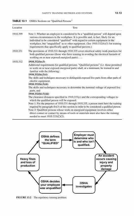
SAFETY TRAINING METHODS AND SYSTEMS 13.13
TABLE 13.1 OSHA Sections on “Qualified Persons”
Location Text
1910.399 Note 1: Whether an employee is considered to be a “qualified person” will depend uponvarious circumstances in the workplace. It is possible and, in fact, likely for anindividual to be considered “qualified” with regard to certain equipment in theworkplace, but “unqualified” as to other equipment. (See 1910.332(b)(3) for trainingrequirements that specifically apply to qualified persons.)
1910.331 The provisions of 1910.331 through 1910.335 cover electrical safety work practices forboth qualified persons (those who have training in avoiding the electrical hazards ofworking on or near exposed energized parts) . . .
1910.332 1910.332(b)(3)Additional requirements for qualified persons. “Qualified persons” (i.e. those permitted
to work on or near exposed energized parts) shall, at a minimum, be trained in andfamiliar with the following:
1910.332(b)(3)(i)The skills and techniques necessary to distinguish exposed live parts from other parts of
electric equipment.1910.332(b)(3)(ii)The skills and techniques necessary to determine the nominal voltage of exposed live
parts, and1910.332(b)(3)(iii)The clearance distances specified in 1910.333(c) and the corresponding voltages to
which the qualified person will be exposed.Note 1: For the purposes of 1910.331 through 1910.335, a person must have the trainingrequired by paragraph (b)(3) of this section in order to be considered a qualified person.
Note 2: Qualified persons whose work on energized equipment involves eitherdirect contact or contact by means of tools or materials must also have the trainingneeded to meet 1910.333(C)(2).
FIGURE 13.2 The regulatory training problem.
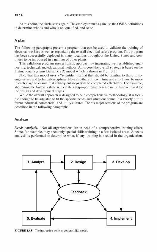
13.14 CHAPTER THIRTEEN
At this point, the circle starts again. The employer must again use the OSHA definitionsto determine who is and who is not qualified, and so on.
A plan
The following paragraphs present a program that can be used to validate the training ofelectrical workers as well as organizing the overall electrical safety program. This programhas been successfully deployed in many locations throughout the United States and con-tinues to be introduced in a number of other plants.
This validation program uses a holistic approach by integrating well established engi-neering, technical, and educational methods. At its core, the overall strategy is based on theInstructional Systems Design (ISD) model which is shown in Fig. 13.3.
Note that this model uses a “scientific” format that should be familiar to those in theengineering and technical disciplines. Note also that sufficient time and effort must be madein each stage to ensure that subsequent steps will be completed effectively. For example,shortening the Analysis stage will create a disproportional increase in the time required forthe design and development stages.
While the overall approach is designed to be a comprehensive methodology, it is flexi-ble enough to be adjusted to fit the specific needs and situations found in a variety of dif-ferent industrial, commercial, and utility cultures. The six major sections of the program aredescribed in the following paragraphs.
Analyze
Needs Analysis. Not all organizations are in need of a comprehensive training effort.Some, for example, may need only special skills training in a few isolated areas. A needsanalysis is performed to determine what, if any, training is needed in the organization.
FIGURE 13.3 The instruction systems design (ISD) model.
SAFETY TRAINING METHODS AND SYSTEMS 13.15
You should consult three sources to assess your needs—employees, supervisors and man-agers, and company performance.
1. Employees. Formally poll your employees for training requirements. Usually theyknow their shortcomings better than anyone. The poll should be concise and sincere. Beprepared for a revelation because experience has shown that, more often than not, employersand employees have very different views about the state of their training.
2. Supervisors and managers. Extend the training poll to your management andsupervision. Give them a chance to tell you where training deficiencies are causing prob-lems. Their input should be solicited for their employees’ and their own training needs. Donot forget to include yourself in this analysis. Employees at all levels may need training.
3. Company performance. An honest evaluation of company performance can be oneof the best sources of training needs assessment. The most obvious example of this elementis in the area of safety. Do some departments have a consistent record of safety problems?Such a department is an obvious target for safety training. Remember to involve youremployees and supervisors in the review and analysis of the material. The people who aregoing to receive the training should be involved at all stages.
An electrical safety audit, as described in Chap. 12, can be used to satisfy all the require-ments of the needs analysis. This comprehensive audit requires a minimum of two days for asmall facility and a maximum of several days for a large facility. A combination of interviews,questionnaires, and site inspections combine to create a thorough assessment of the existingconditions. An exit presentation is held with key plant personnel to review critical findings. Inmost cases, severe hazards are discovered during the audit which can be corrected on the spot.A comprehensive report follows the audit within two weeks. This report details the findingsand recommendations of the audit and is the first concrete step in the process.
Job and Task Analysis. After the needs analysis is complete, you should have a well-defined set of training needs. The next step is the performance of a job and task analysis(JTA) for each of the areas which require training. This critical step defines the actual com-position of a given job. The JTA involves the following three steps.
1. Employee interviews. Each employee is interviewed, and a listing is made of thejobs and tasks that he or she performs. The listing should be very detailed to allow for thedevelopment of performance objectives.
2. Supervisor and manager interviews. The department supervisors are interviewedto obtain their input to the jobs and tasks performed by their employees. This listing is com-pared to the one developed by the employee interviews, and modifications are made asrequired. Many training problems disappear when this step is performed since supervisorsand employees develop a common understanding of the task at hand.
3. Job performance observation. Employees are observed in the performance of theirjobs. The job and task listings developed during the interviews are reviewed and refined tobe consistent with actual performance. Remember that the actual performance of the givenjob is under question, so do not modify a JTA based on performance observation unless youare certain that the job is being performed correctly.
The arc-energy analysis. An arc-energy analysis which includes a short-circuit study,coordination study, and flash-hazard analysis is a critical part of the analysis stage andshould be performed if it is not already available. Some companies may prefer to performa “mini-study” before any of the other steps to determine the severity of the flash hazard attheir location. The results of this study will determine the minimum PPE requirements forworkers, provide the required flash-hazard warning labels for each location, and introduceoverall electrical safety requirements to plant personnel.
13.16 CHAPTER THIRTEEN
Because of the perceived cost of such a study, many companies opt for the use of theso-called simplified method as described in NFPA70E, and discussed in Chap. 3. Theauthors of this book discourage this practice for several reasons including:
1. The simplified method requires knowledge of much of the same baseline data includingshort circuit duties and clearing times.
2. The simplified method frequently results in an over-dressed work force. In fact, if doneconservatively, it should.
3. We have documented situations in which the simplified method actually results inunder-dressing personnel. That is, even when correctly applied, the simplified methodmay give results that will not provide adequate protection. While this occurrence is rare,even one time could result in severe injuries or death.
4. While most will agree that the current arc-energy calculation methods are a work inprogress, they still provide the best available information of the degree of exposure. Weowe our workers our best possible effort in determining the risk and attendant protectionmethods.
Design
Performance Objective Design. Based upon the results of the JTA, a set of measurableperformance objectives is developed. You may wish to develop training objectives in twotiers—terminal objectives and enabling objectives. Terminal objectives are broad-basedobjectives that represent the actual required behavior. Enabling objectives are “sub” objec-tives that define skills required to meet a given terminal objective. The following giveexamples.
Terminal objectives. The employee will be able to test a Westinghouse induction diskovercurrent relay. The tests will be performed using the manufacturer’s instruction leaflet,a transformer-loaded overcurrent relay test set and associated instructions, and thecompany-supplied test sheet. Test results shall be as defined in the relay instruction leaflet.
Enabling objectives
1. The employee will be able to describe the purpose and use of each of the controls onthe transformer-loaded test set.
2. The employee will be able to describe the pickup and timing adjustments on theWestinghouse induction disk overcurrent relay. (Add other objectives as defined fromthe JTA.)
Note the specificity of the objectives. The regulations and standards are very clear in therequirement that employees must be trained on the equipment with which they work.
Structure Design. The information generated during the needs analysis, JTA, and per-formance objectives development is reviewed, and an overall structure for the trainingeffort is defined. Of course, not all companies are going to need a large, expensive trainingcenter with a staff of trainers.
In-house training. If you define an extensive training need with many ongoing courserequirements, you may need to consider the development and use of an in-house trainingsystem. The materials for such training can include both specifically developed and/orvendor-supplied materials. On-the-job training is usually a very important part of in-housetraining.

SAFETY TRAINING METHODS AND SYSTEMS 13.17
Vendor-supplied training. Specific skills such as cable testing, relay testing, breakertesting, and instrument repair may best be supplied by training companies that specializein these areas. In fact, in some cases an entire program may be implemented throughcommercially purchased training.
Self-study. Many skills can be learned effectively through one of the many self-studyprograms that are commercially available. Even if a program of this type is not purchased,employees should be encouraged (monetarily if necessary) to put in some study time ontheir own.
Infrastructure Design
1. Training department organizationa. The training department should report to the executive level of management. This is
especially important for technical training departments.b. Training department supervisors should be technically qualified personnel.
Furthermore, training supervisors should maintain a teaching schedule.c. Salaries for training department personnel should be equal to or exceed the salaries
of equivalent level personnel in other departments.2. Training facilities. The selection of a training facility will depend upon the quantity and
nature of the training that you wish to conduct. If you plan to use a lot of outside ven-dors, you may be able to use their facilities. Conference rooms, local meeting centers,and hotel facilities may also be viable alternatives. Specialized laboratory needs mayrequire the construction of facilities. As an alternative to this, you may consider usingyour company work areas for laboratories; however, this is not recommended as a generalpractice.
Develop
Overall Training Structure. In some cases the required training will be minimal andperhaps limited only to the specific qualification exercises necessary to assure that allworkers have the requisite technical and safety skills to perform their work safely. However,it should always be recalled that OSHA requires skilled personnel to be familiar with thehazards as well as the operation of the equipment. This means that every worker must havea solid grounding in the hazards of electricity along with the various specific job require-ments. This means that the final training program will be a mix of several different trainingscenarios including:
1. Prerequisite skills training from apprenticeship programs, public education, and/orvalidated on-the-job programs. The proof of such training may be a prerequisite forobtaining a job.
2. Formal classroom training to be attended by all personnel as they progress through theirjob structure. Such training may be either:a. Internally developed and presented classes orb. External training from vendors, vocational schools, or community colleges. c. Formal on-the-job training requiring demonstration of skills in the presence of a
supervisor with an appropriate qualification form.
Whatever the mix of training, there is only one way to ensure that workers are trulyqualified. They must demonstrate their competence in a controlled environment, undersupervision. To be fully qualified, a worker must be trained on a switch of the exact typethat he/she will encounter in the field. Trainees must demonstrate to a supervisor where all
13.18 CHAPTER THIRTEEN
of the hazardous locations are and what steps/precautions should be taken to prevent anaccident. Figure 13.1 is a section of an employee on-the-job training qualification form fortechnical skills. Such forms should be used along with examinations and field demonstra-tions to insure that workers are capable of performing all of the tasks to which they maybe assigned.
Course Development. Courses must be developed or purchased to fulfill the objectivesdefined during the setup step.
1. Purchased materials. Both self-study and classroom materials are available forpurchase from a variety of training vendors. Make certain that the purchased materials meetthe objectives defined during the setup step.
2. Developed materials. Although somewhat more expensive, developing company-specific course materials has some distinct advantages. In the first place, your employees willtend to identify with materials that are obviously site-specific; moreover, presentation time isoptimized since all material is company-specific. Note that these materials may be developedeither by in-house personnel or by consultants.
Implementation
The format of training implementation depends to a large extent on the structure of thefacility and the training needs of the workers as determined in previous sections. However,the correct implementation is absolutely essential in the validation process. At each stepthe workers must demonstrate their knowledge of the operation and the hazards of theequipment that they work on; moreover, they must demonstrate their ability to plan aheadand avoid those hazards by using appropriate work practices, PPE, and other precautionsas required.
Of course examinations and hands-on exercises will be developed based on the job taskanalysis and other assessments discussed previously. Any missed questions should bereviewed with the student until he/she understands why they missed them, and has demon-strated their ability to answer similar questions correctly. In other words, where safety is atrisk, 70 percent is not a passing grade. In fact, anything less than 100 percent success isinsufficient when safety is involved.
The actual presentation of the training program will depend upon the extent and typeof training being implemented. Some courses may be presented on an ongoing basis. Forexample, skills updates such as cable testing, motor and generator maintenance, and thelike may be repeated immediately before maintenance intervals that will require thoseskills. Safety training should be repeated frequently, especially in areas such as lifesavingand CPR.
Training in areas such as basic electricity, mathematics, and other such topics is usuallyperformed only once per employee. Large companies may need to schedule such trainingon a regular basis to allow for turnover. Smaller companies, however, may opt to use self-training or correspondence courses for such topics.
Evaluation
Although evaluation is identified as a separate step, it should be an ongoing effort employedat every level of the training program. Five basic elements of the training program may beused to analyze its effectiveness—test review, course critiques, employee interviews, coursecontent, and needs analysis.
SAFETY TRAINING METHODS AND SYSTEMS 13.19
Test Review. Examinations evaluate the student, the instructor, and the course. They shouldbe administered for every training course. Tests should be reviewed for a variety of prob-lems such as
Commonly missed questions. If one question or group of questions is consistentlymissed by all students, you have a problem with the instructor and/or the course.
Consistently high or low grades. If the average grades on a test are consistently high orlow, the course is probably too easy or difficult, respectively. Another possible cause ofsuch a problem is that the course material does not fulfill the course objectives.
Course Critiques. Carefully review the course critiques for trouble spots. Consistentlyhigh or low evaluations may be an indication of a problem. Take the occasional “sourgrapes” critique with a grain of salt.
Employee Interviews. Periodically interview employees to keep your finger on theirpulse. Make certain that the employees are learning and that the training program is accom-plishing what you intended.
Course Content. Electrical technology is changing rapidly. Although basic electricalprinciples remain the same, testing technology changes rapidly. Periodically you must haveyour course materials reviewed for technical accuracy and relevance. Nothing frustratesstudents more than learning yesterday’s technology.
Needs Analysis. Periodically update the performance of the needs analysis. Makecertain that the desired behavioral objectives are being met. Ask the following questions:
1. Has company performance improved as desired?
2. Is employee and supervisor morale at the levels you wished to achieve?
3. Is your company safety record acceptable?
A Training Program Tracking Program. Keeping track of the feedback received duringthe various portions of the program is a monumental task, especially for very large compa-nies. A training program tracking program should be implemented to document and verifyall of the various training steps.
For example, during training implementation, records are stored in an electronicdatabase. Forms, queries, and reports are structured to allow the user to search for infor-mation relating to employees, hazards, or departments. Individual status reports are quicklyand easily accessible, and show each hazard for which the individual has completed train-ing. Such record keeping is critical to optimize safety and to serve as proof of trainingshould an OSHA investigation occur.
Whatever criteria were used to establish the original need for the training program mustbe evaluated. If the desired changes have occurred, then the program is meeting its goals.
Modification
Update and modify your training program based on your evaluation. Although this mayseem obvious, a surprising number of companies evaluate their programs and then make nochanges. An evaluation is useless if no changes are implemented.

This page intentionally left blank
AAFS (see American Academy of ForensicSciences)
ABA (Advanced Burn Life Support guidelines),8.12
Abrasions (in rubber goods), 2.33, 2.35AC (see Alternating current)Access plates, for rotating equipment, 5.23Accident investigation, 7.37–7.41
accident analysis in, 7.40–7.41data gathering for, 7.38–7.40employee safety team in, 12.8–12.9general rules for, 7.38purpose of, 7.37, 7.38
Accident prevention, 7.1–7.7and first aid training, 7.7–7.8 (See also First
Aid)individual responsibility for, 7.1, 7.2installation safety for, 7.1–7.3power system studies for, 7.3–7.7
Advanced Burn Life Support guidelines (ABA),8.12
A-frame hoist, 7.35Afterglow, 2.3Age cracks (in rubber goods), 2.33, 2.36AIEE (American Institute of Electrical
Engineers), 6.3Airline industry, RCM in, 5.5Alternating current (AC):
circuits requiring grounding, 9.9grounding of conductors for, 4.11power supplies for electronic circuitry, 9.22service-supplied, grounding of, 4.9–4.11and severity of shock, 1.4
American Academy of Forensic Sciences(AAFS), 6.13, 7.38
American Burn Association, 6.13American Institute of Electrical Engineers
(AIEE), 6.3
American National Standards Institute (ANSI),2.14, 6.1–6.2, 6.13
American Red Cross rescue method, 7.16, 7.17American Society for Testing and Materials
(ASTM), 2.4, 2.16, 6.4–6.5, 6.13American Society of Safety Engineers (ASSE),
6.5–6.6, 6.13American Society of Training and Development,
6.13ANSI (see American National Standards Institute)ANSI C-2 (see National Electrical Safety Code)ANSI standards:
for electrical grounding, 9.5, 10.3for eye protection, 9.15for hard hats, 9.14, 10.8for power systems studies, 7.4for short-circuit analyses and coordination
studies, 7.7ANSI/NFPA 70 (see National Electrical Code)ANSI/NFPA 70B (see Electrical Equipment
Maintenance)ANSI/NFPA 70E (see Standard for Electrical
Safety in the Workplace)Approach distances, 3.46–3.51
barriers and warning signs for, 3.56,3.60–3.61
flash hazard distance, 3.46, 3.49–3.51with high- and medium-voltage systems and
equipment, 10.12–10.13and illumination, 3.61with low-voltage systems and equipment, 9.20protective clothing for, 3.56–3.60shock hazard distance, 3.46–3.48terms related to, 3.46, 3.47
Arc (electric), 1.7–1.16blasts formed by, 1.16burns from, 1.16defined, 1.1, 1.8
I.1
INDEX
Copyright © 2006 by The McGraw-Hill Companies, Inc. Click here for terms of use.
I.2 INDEX
Arc (electric) (Cont.):description of, 1.8–1.9effects of, 1.24energy input to, 1.12–1.13energy release from, 1.9, 1.12flash and thermal protection from, 2.2–2.13incident energy of, 1.14–1.16procedural protection strategy for, 1.24protective equipment for, 1.24, 2.2surface area of, 1.13–1.14and voltage magnitude, 1.4voltage of, 1.13
Arc energy input, 1.1Arc incident energy, 1.1Arc protection:
calculations for, 3.51–3.62with high- and medium-voltage systems,
10.9with low-voltage systems, 9.18
Arc Thermal Performance Value (ATPV):calculation of, 2.1defined, 2.1developing rating for, 2.9evaluation of, 2.3
Arc-energy analysis, 13.15–13.16Arc-flash, 1.1Arc-flash study, 7.7Arc-in-a-box, 3.52Arcing current, 1.12–1.13, 3.53, 3.54Arc-resistant switchgear, 1.1–1.2Area enclosures, maintenance of, 5.15Artificial respiration, 7.12–7.14ASSE (see American Society of Safety
Engineers)ASSE standards, 6.6ASTM (see American Society of Testing and
Materials)ASTM standards, 2.5, 6.4–6.5, 6.19–6.21ATPV (see Arc Thermal Performance Value)Attendants, hazard, 2.50Audiovisual proximity tester, 2.56Audit teams, 12.14Audits (see Safety audits)Authorized controller (lockout/tagout), 3.29Authorized employee (lockout/tagout), 3.29
Barricades:for temporary hazards, 2.50
Barrier tape, 2.49–2.51Barriers:
for approach distances, 3.56, 3.60–3.61for rotating equipment, 5.23
BASOFIL®, 2.7Batteries, stationary, 9.23–9.25Behavioral approaches to safety, 7.1, 7.2Behavioral modification, 13.1–13.2Blanket drag, 7.36Blankets, rubber, 2.21–2.23, 2.29, 2.31Blast (electric), 1.16–1.18
defined, 1.2procedural protection strategy for, 1.24protective equipment for, 1.24
Blood vessels, 1.20Body (see Human body)Bonding, 4.18–4.19
connection of equipment for, 4.8–4.9defined, 4.2of electrically conductive materials, 4.6–4.7of equipment, 4.6–4.7general requirements for, 4.2–4.9grounding vs., 9.6, 10.4
Bonding jumper:defined, 4.2equipment, 4.2main, 4.2and system grounding, 4.11–4.12
Breakers, locking devices for, 2.53, 2.54Breathing, 1.7 (See also Pulmonary system)Brown Book (IEEE), 7.7Burns:
from arcs, 1.16, 1.20, 1.21categories of, 1.16first aid for, 7.11–7.13heart damage from, 1.23from shock, 1.3sources of, 1.20
Cable ampacity analysis, 7.5Cables, jumper, 2.66, 2.67, 2.70, 2.72, 2.73Cadick, John, 5.10Canadian Society of Forensic Sciences (CSFS),
6.13, 7.38Capacitive discharges, 9.21Carbon monoxide exposure, 7.30, 7.31Cardio-pulmonary resuscitation (CPR),
7.12–7.16CBM (see Condition Based Maintenance)Cell wall damage, from shock, 1.3CEST (see Company electrical safety team)Chair carry, 7.38Chemical bloom (in rubber goods), 2.33, 2.36Chemically treated materials, 2.6Chernobyl Nuclear Power Station, 11.2Chest compressions, 7.14–7.16
Circuit breakers:failure of, 5.17low voltage, 5.18–5.20medium voltage, 5.20–5.21molded-case, 5.16–5.18
Clamps, jumper, 2.66–2.68, 4.9Classroom training, 13.3–13.5Cleaning, in Eight Step Maintenance Program,
5.12Cleared circuits (see De-energized circuits)Closed-door operation:
of low-voltage switchgear, 3.10, 3.12,3.14–3.15
of medium-voltage switchgear, 3.10–3.11of motor starters, 3.21–3.23
Clothes drag, 7.36Clothing:
for approach distances, 3.56–3.60comparison of material characteristics, 2.7conductive, 3.61for crossing flash hazard boundary, 3.59flame-resistant materials for, 2.6–2.9flash suits, 2.11–2.13ignition temperatures and fiber types, 1.8non-flame-resistant materials for, 2.5thermal protective, 2.2–2.5, 2.9, 2.11work, 2.9–2.11
Cognitive ergonomics, 11.1, 11.4–11.7Color splash (in rubber goods), 2.36, 2.37Company electrical safety team (CEST),
12.2–12.4Condition Based Maintenance (CBM), 5.9, 5.14Condition-directed maintenance, 5.7Conductive clothing, 3.61Conductive materials, bonding of, 4.6–4.7Conductors:
in AC systems, 4.11grounding, 4.2, 4.11grounding electrode, 4.3maintenance of, 5.15
Confined work spaces:avoiding hazards in, 3.62rescues from, 7.30–7.36
Construction industry:electrical fatalities in, 8.1–8.5installation safety standards, 6.23,
6.165–6.184OSHA standard definitions for, 6.23,
6.188–6.194OSHA standards, 6.22–6.23safety standards for special equipment, 6.23,
6.187
safety-related maintenance and environmentalconsiderations standards, 6.23, 6.186
safety-related work practices standards, 6.23,6.185
Construction work clothing, 2.9–2.11Consultants, training by, 13.9–13.11Contact testers, 2.56–2.59Contractor muscle, 1.2Cord-connected equipment:
grounding of, 4.19–4.21low-voltage safety with, 9.3–9.5OSHA standards for, 4.20(See also Extension cords)
Correspondence schools, 13.9Cotton clothing materials, 2.5Course critiques (training), 13.19Covers, rubber, 2.22, 2.24–2.25CPR (cardio-pulmonary resuscitation) (see
Heart-lung resuscitation)CSFA (see Canadian Society of Forensic
Sciences)CTs (see Current transformers)Current transformers (CTs):
in high- and medium-voltage safety, 10.1–10.2in low-voltage systems, 9.5in power protection scheme, 5.22
Current(s):alternating (see Alternating current)arcing, 1.12–1.13direct (see Direct current)objectionable, 4.8severity of shock and duration of, 1.3severity of shock and magnitude of, 1.5–1.7temporary, 4.8
Curriculum development, 13.10–13.11Cuts (in rubber goods), 2.36, 2.37
DC (see Direct current)Deaths:
causes of, 1.25in construction industry, 8.1–8.5cost-related, 8.4–8.6from electrical events, 8.7–8.8statistical survey of, 8.1–8.6
De-energized (cleared) circuits:safety procedures and methods, 3.3–3.6steps before working with, 3.6verification of isolation, 3.28
De-energizing equipment, energy control rulesfor, 3.24–3.25
Depressions (in rubber goods), 2.37Design of electrical systems, 7.1–7.3
INDEX I.3
Design safety standards, OSHA, 6.22, 6.24–6.47Detergent cracks (in rubber goods), 2.37Digital multimeter, 2.57, 2.58Digital readout safety voltmeter, 2.57, 2.58Direct current (DC):
circuits requiring grounding, 9.8power supplies for electronic circuitry, 9.22and severity of shock, 1.4
DOT rules, 8.17Double-insulated tools, 9.3Duct systems, grounding of, 4.6, 4.7DuPont Company, 2.6
EBT (Energy break-through), 2.1Economic case for electrical maintenance,
5.3–5.4Educational objectives, 13.2EEST (see Employee electrical safety teams)Effectively grounded, 4.2The Eight Step Maintenance Program
(John Cadick), 5.10–5.14Electric arc (see Arc [electric])Electric blast (see Blast [electric])Electric shock (see Shock [electric])Electrical accident fatality, 8.7Electrical Equipment Maintenance—
ANSI/NFPA 70B, 6.15–6.16for maintenance, 5.1for short-circuit analyses and coordination
studies, 7.7Electrical events, 8.6–8.8
arc (see Arc [electric])blast (see Blast [electric])deaths from, 8.7–8.8electrocution, 8.7–8.8non-electrical effects in, 8.10–8.13physical responses to, 8.11, 8.12possible trauma following, 8.9, 8.10schematic of, 8.8–8.9shock (see Shock [electric])survivor experience, 8.11–8.13
Electrical hold, 1.7loss of control during, 1.21and muscular system, 1.22
Electrical injury mortality, 8.7Electrical maintenance, 5.1–5.24
area enclosures, 5.15conductors, 5.15economic case for, 5.3–5.4eight-step maintenance program, 5.10–5.14electrical insulation, 5.16enclosures, 5.15
frequency of, 5.14fuses, 5.16general requirements for, 5.14–5.15low-voltage power circuit breakers, 5.18–5.20medium voltage circuit breakers, 5.20–5.21molded-case circuit breakers, 5.16–5.18OSHA standards for, 6.23, 6.186personal safety/protective equipment, 5.24portable electric tools/equipment, 5.23–5.24protective devices, 5.16protective relays, 5.21–5.23Reliability-Centered Maintenance, 5.4–5.10rotating equipment, 5.23safety-related case for, 5.1–5.3
Electrical paralysis, 1.21, 1.22Electrical safety program, 12.1–12.34
company electrical safety team, 12.2–12.4development of, 12.2–12.8employee safety teams, 12.3–12.4, 12.8–12.9outage reports, 12.11safety audits, 12.11–12.34safety meetings, 12.9–12.11structure of, 12.1–12.2in training program, 13.12–13.19
Electrical testing:for rubber-insulating equipment, 2.43–2.44of tools and extension cords, 3.63
Electrically conductive materials, bonding of,4.6–4.7
Electrician’s safety kit, 2.78, 2.79Electrocution, 8.7–8.8
deaths from, 8.1defined, 1.2
Electronic circuitry:grounding of workers with, 9.1safety around, 9.21–9.23
Electroporation, 1.3, 1.4Elevated rescue, 7.18–7.29Embedded foreign matter (in rubber goods),
2.37Employee electrical safety teams (EEST),
12.3–12.4, 12.8–12.9Employee interviews (training evaluation), 13.19Enabling training objectives, 13.16Enclosed switches and disconnects, 3.17–3.18Enclosures, maintenance of, 5.15Energized, defined, 4.2Energized circuits:
costs requiring, 3.5decision tree for, 3.4, 3.5safety procedures and methods for, 3.3–3.6work requiring, 3.6
I.4 INDEX
Energy, incident, 1.14Energy break-through (EBT), 2.1Energy control programs, 3.23–3.26Energy control rules:
for de-energizing equipment, 3.24–3.25for procedures involving more than one
person, 3.25–3.26for reenergizing equipment, 3.25
Energy input (arcs), 1.12–1.13Energy release (arcs), 1.9, 1.12Environmental issues, OSHA standards for,
6.23, 6.186Epidermis, 1.19, 1.20Equipment:
bonding of, 4.6–4.7construction, OSHA standards for, 6.23,
6.187defined, 4.2improper maintenance of, 5.2–5.3portable, 5.23–5.24safety (see Safety equipment)(See also specific types)
Equipment grounding, 4.6, 4.19–4.26conductors for, 4.21–4.26cord- and plug-connected equipment,
4.19–4.21and ferroresonance, 4.25–4.26ground-fault protection, 4.3grounding and bonding, 4.8for high- and medium-voltage systems, 10.7for low-voltage systems, 9.11–9.13
Equipotential grounding, 3.38, 3.43–3.44Ergonomics, 11.1, 11.4–11.7Evacuation, medical, 8.12Evaluation:
in Eight Step Maintenance Program,5.13–5.14
of on-the-job training, 13.8–13.9of training programs, 13.11, 13.18–13.19
Experimentation (accident investigation), 7.40Extension cords:
low-voltage safety with, 9.2–9.3testing of, 3.63
Extensor muscle, 1.2, 1.21Eye protection, 2.13, 2.15, 2.16
for high- and medium-voltage systems,10.8–10.11
for low-voltage systems, 9.15–9.17
Face shields, 2.12, 2.15Facilities life cycle, impact of maintenance on,
5.9–5.10
Failure:of circuit breakers, 5.17defined, 5.8
Failure Modes and Effects Analysis (FMEA),5.6, 8.6–8.7
Failure-finding maintenance, 5.7Fatalities (see Deaths)Fault path, performance of, 4.8Ferroresonance, 4.25–4.26Ferrules, jumper cable, 2.66, 2.69–2.73Fibrillation, 1.2, 1.3, 1.7Field testing:
of rubber goods, 2.29–2.35of voltage testers, 2.62
Fire scene ratings, 8.7Firefighter’s carry, 7.36First aid, 7.7–7.16
ABCs of, 7.9–7.10for electric shock, 7.11–7.13for electrical burns, 7.11–7.13general procedures for, 7.8–7.11heart-lung resuscitation, 7.12–7.16resuscitation (artificial respiration), 7.12–7.14
First-degree burns, 1.16Fittings, protection of, 4.9Flame resistance (FR):
defined, 2.1and energy break-through, 2.3evaluation of, 2.3for protective clothing, 2.4–2.5
Flame retardant, defined, 2.1Flame-resistant materials, 2.6–2.9Flammable, defined, 2.1Flash (see Arc [electric])Flash boundary, 2.1, 2.3Flash hazard:
calculating protection for, 3.51–3.62distance for, 3.46, 3.49–3.51IEEE Std 1584–2002 methods of calculating,
3.53–3.55Lee method of calculating, 3.52NFPA 70E methods of calculating, 3.52, 3.53PPE for crossing boundary for, 3.55software solutions for calculating, 3.53–3.55
Flash line (in rubber goods), 2.40Flash protection:
safety equipment for, 2.2–2.13thermal performance evaluation, 2.3–2.4thermal protective clothing, 2.2, 2.3
Flash suits, 2.11–2.13Flexible cord sets (see Extension cords)Flexor muscles, 1.21
INDEX I.5
FMEA (see Failure Modes and EffectsAnalysis)
Form marks (in rubber goods), 2.37FR (see Flame resistance)FR Cotton, 2.7FR Polyester, 2.7Frequency:
with electronic circuitry, 9.21and severity of shock, 1.3–1.4
FR9B®, 2.7Full body rope harness, 7.32Functional failure, 5.8Fuses, maintenance of, 5.16
General industry standards (OSHA), 6.19, 6.22,6.156–6.164
GFCIs (see Ground fault circuit interrupters)Gin pole hoists, 7.34, 7.35Gloves, rubber, 2.16–2.20, 2.29–2.35Goggles, 2.15, 2.16Ground, defined, 4.2, 9.5Ground fault circuit interrupters (GFCIs),
2.74–2.76, 4.3, 4.20, 9.14Ground mat analysis, 7.5Ground rods/pipes, 4.12–4.15Grounded:
defined, 4.2effectively, 4.2
Ground-fault protection of equipment, 4.3Grounding, 4.1–4.27
bonding vs., 9.6, 10.4connection of equipment for, 4.8–4.9and electric shock hazard, 4.1–4.2of equipment, 4.19–4.26, 9.11–9.13, 10.7equipment used for (see Grounding equipment)general requirements for, 4.2–4.9of high- and medium-voltage systems,
10.3–10.7of low-voltage systems, 9.5–9.14need for, 2.63–2.64to prevent objectionable current, 4.8of systems, 4.9–4.19, 9.8–9.11, 10.5–10.6
Grounding conductor, 4.2equipment, 4.2for equipment grounding, 4.21–4.26
Grounding electrode conductor, 4.3, 4.14–4.16Grounding electrode system, 4.3, 4.12–4.14Grounding equipment, 2.63–2.74
cables, 2.66, 2.67, 2.70, 2.72, 2.73clamps, 2.66–2.68ferrules, 2.66, 2.69–2.73installation and location of, 2.74
jumpers, 2.65–2.73and need for grounding, 2.63–2.64switches, 2.64, 2.65
Ground-level rescue, 7.31, 7.34–7.38“Group” padlocks, 2.52Guards, for rotating equipment, 5.23
Hand protection, 2.13Hand tools:
grounding of, 4.19–4.21insulated, 2.48–2.49low-voltage safety with, 9.3–9.5
Hard hats, 2.14, 2.16for high- and medium-voltage systems, 10.8for low-voltage systems, 9.14
Hard spots (in rubber goods), 2.37–2.39Harmonic analysis, 7.4Hazardous energy source control, 6.22,
6.139–6.155 (See also Lockout/tagout)Hazardous environments, use of tools in, 3.63Hazards of electricity, 1.1–1.25
arc, 1.7–1.16blast, 1.16–1.18body parts affected by, 1.17, 1.19–1.23causes of injury and death, 1.23–1.25with electronic circuitry, 9.21–9.22field marking of, 3.65and improper maintenance of equipment,
5.2–5.3protective strategies, 1.25shock, 1.2–1.7with stationary batteries, 9.25voltage hazards, 9.6–9.8
Head protection, 2.13–2.16Health and safety department (HSD), 12.2–12.3Heap, Howard, 5.5, 5.8Heart, 1.22–1.23
burn damage to, 1.23fibrillation of, 1.2, 1.3, 1.7shock damage to, 1.23
Heart-lung resuscitation (CPR), 7.12–7.16High- and medium-voltage safety, 10.1–10.13
current transformers, 10.1–10.2equipment for, 10.7–10.12flash protection boundary, 3.50–3.51grounding, 10.3–10.7procedures for, 10.12–10.13
High Voltage Rescue Technique, 7.16, 7.17Hoechst Celanese Corporation, 2.6Horny layer, 1.19
defined, 1.2and electrical resistance, 1.20
I.6 INDEX

Hospitalization of victims, 8.14Hot stick kit, 2.45–2.47Hot sticks, 2.44–2.48, 3.38Hot work (see Energized circuits)HSD (see Health and safety department)Human body:
arc effects on, 1.8–1.12, 1.24body parts affected by electricity, 1.17,
1.19–1.23heart, 1.22–1.23muscular system, 1.21–.122nervous system, 1.20, 1.21nominal resistance values for parts of, 1.6pulmonary system, 1.23response to current magnitudes, 1.7shock effects on, 1.2–1.3, 1.6, 1.23skin, 1.19–1.21tolerance to heat, second-degree burns, 3.50
Human factors in safety, 11.1–11.8background of, 11.1–11.3meanings of term, 11.2and power systems, 11.3–11.7
Hydrogen sulfide exposure, 7.30, 7.31
IAS Electrical Safety Workshop, 6.13IEC (see International Electrotechnical
Commission)IEEE (see Institite of Electrical and Electronic
Engineers)IEEE standards:
for calculating flash hazard, 3.53–3.55for conductor size, 4.17for electrical grounding, 9.5, 10.3for power systems studies, 7.4
Illumination of work areas, 3.61Incident energy:
of arcs, 1.14–1.16calculation of, 3.54–3.55
Indentations (in rubber goods), 2.37Infrastructure design (for training), 13.17In-house training, 13.16Injury:
causes of, 1.24–1.25cost-related, 8.4–8.6electrical injury mortality, 8.7to muscles and peripheral nerves, 8.15non-occupational, 8.4statistical survey of, 8.1–8.6
Inspection, 2.2in Eight Step Maintenance Program, 5.11–5.12of rubber-insulating equipment, 2.29–2.44safety audit vs., 12.11–12.12
timing of, 2.2of tools and test equipment, 3.63with tools/instruments, 5.11–5.12unaided, 5.11of voltage-measuring instruments, 2.59
Installation:accident prevention during, 7.1–7.3
Instantaneous trip units, 5.23Institite of Electrical and Electronic Engineers
(IEEE), 6.3, 6.13Instructional Systems Design (ISD) model, 13.14Instructors, training, 13.4Instruments, voltage-measuring (see Voltage-
measuring instruments)Insulated tools, 2.48–2.49, 9.3Insulation:
electrical, 5.16insulated tools, 2.48–2.49, 9.3for jumper cables, 2.67maintenance of, 5.16rubber insulated equipment, 2.29–2.44 (See
also Rubber insulating equipment)InterNational Electrical Testing Association
(NETA), 5.1, 5.12, 5.13, 6.13International Electrotechnical Commission
(IEC), 6.2, 6.13International Organization for Standardization
(ISO), 6.2, 6.13Ionizing hazards, 9.22–9.23ISD model, 13.14ISO (see International Organization for
Standardization)
Job and task analysis, 13.10, 13.15Jumper, bonding, 4.2Jumpers, safety grounding (safety grounds),
2.65–2.73cables, 2.66, 2.67, 2.70, 2.72, 2.73clamps, 2.66–2.68ferrules, 2.66, 2.69–2.72selection of, 2.70, 2.72–2.73
Keratin, 1.20KERMEL®, 2.6, 2.7KEVLAR®, 2.7
Laboratory training, 13.3–13.4Lead-acid batteries, 9.24Leather protectors, 2.19Lee, Raphael C., 1.3, 1.9, 1.14, 3.52Lee Method, 1.14–1.15“Let-go” threshold, 1.4
INDEX I.7

Line hose, 2.25–2.26, 2.29Litigation, accident, 7.37, 7.38Load flow analysis, 7.4Lockout/tagout, 3.26–3.32
applications for, 3.28control bypass for, 3.29–3.31control transfer for, 3.31employee responsibilities for, 3.27–3.28with high- and medium-voltage systems and
equipment, 10.13isolation verification, 3.28locks without tags, 3.27with low-voltage systems and equipment, 9.21by nonemployees and contractors, 3.31normal removal of, 3.28–3.29OSHA standards for, 6.22procedural reviews for, 3.32removal of, 3.28–3.31rules for using locks and tags, 3.27safety ground application with, 3.29, 3.31sequence for, 3.28SHA standards for, 6.139–6.155tags without locks, 3.26–3.27training for, 3.31when/where to use, 2.53–2.55, 3.26
Locks and locking devices, 2.51–2.55 (See alsoLockout/tagout)
Low voltmeter safety standards, 2.60, 2.61Low-voltage measuring instruments, 2.62–2.63Low-voltage power circuit breakers,
maintenance of, 5.18–5.20Low-voltage safety, 9.1–9.25
arc hazard, 1.9current transformers, 9.5equipment for, 9.14–9.19extension cords, 9.2–9.3flash protection boundary, 3.49, 3.50grounding, 9.5–9.14on or near electronic circuitry, 9.21–9.23plug- and cord-connected equipment, 9.3–9.5procedures for, 9.20–9.21with stationary batteries, 9.23–9.25
Low-voltage switchgear:closed-door operation of, 3.10, 3.12, 3.14–3.15open-door operation of, 3.10, 3.15safety procedures/methods with, 3.11–3.15
Lubrication, in Eight Step MaintenanceProgram, 5.12–5.13
Main bonding jumper, 4.11–4.12Maintenance, 7.3 (See also Electrical
maintenance)
“Maintenance Testing Specifications forElectrical Power Distribution Equipmentand Systems” (NETA), 5.1
Manufacturer’s seminars, 13.9Materials, training, 13.4, 13.10, 13.18Mats, rubber, 2.20, 2.29Medical aspects of electrical trauma, 8.8–8.17
medical and surgical intervention, 8.14–8.16non-electrical effects in electrical events,
8.10–8.13rehabilitation and return to work, 8.16stabilization and initial evaluation, 8.13–8.14statistical survey of known injuries/fatalities,
8.1–8.6Medical interventions, 8.14–8.16Medium voltage circuit breakers, maintenance
of, 5.20–5.21Medium-voltage safety, 3.50–3.51, 10.1n. (See
also High- and medium-voltage safety)Medium-voltage switchgear:
closed-door operation of, 3.10–3.11open-door operation of, 3.10, 3.11safety procedures/methods with, 3.7–3.11
Meetings, safety, 12.8–12.11Mesh voltage hazards, 9.7, 10.5Mold marks (in rubber goods), 2.37, 2.40Molded-case circuit breakers:
locking devices for, 2.53, 2.54maintenance of, 5.16–5.18safety procedures/methods with, 3.15–3.17
Motor starters:closed-door operation of, 3.21–3.23open-door operation of, 3.23safety procedures/methods with, 3.20–3.23
Motor-starting analysis, 7.4Mouth-to-mouth resuscitation, 7.13–7.14Multiple-lock devices, 2.52–2.53, 2.55Muscles:
contractor, 1.2electrical hold, 1.7extensor, 1.2, 1.21flexor, 1.21“Let-go” threshold, 1.4
Muscular system, 1.21determination of injuries to, 8.15shock damage to, 1.21–1.22
National Electrical Code (NEC)—ANSI/NFPA70, 2.75, 4.1, 6.14–6.15
bonding, 4.18cord- and plug-connected equipment,
4.19–4.20
I.8 INDEX
equipment grounding conductors, 4.21–4.22,4.25, 9.11, 9.12
equipment to be grounded, 4.19, 9.11–9.13ground-fault protection for temporary wiring,
4.20grounding electrode conductor installation,
4.15–4.16grounding of electrical systems, 4.3–4.6grounding service-supplied AC systems,
4.10–4.11performance of fault path, 4.8safety requirements, 5.3
National Electrical Manufacturer’s Association,6.13
National Electrical Safety Code (NESC)—ANSIC-2, 4.16, 6.12–6.14
National Electrical Safety Foundations (NESF),6.13
National Fire Protection Association (NFPA),6.3–6.4, 6.13, 8.6
Natural fibers, as non-flame-resistant, 2.5NEC (see National Electrical Code)Needs analysis, 13.10, 13.14, 13.15, 13.19Neon light proximity tester, 2.55, 2.56Nervous system, 1.3, 1.20, 1.21, 8.15NESC (National Electrical Safety Code), 4.16NESF (National Electrical Safety Foundations),
6.13NETA (see InterNational Electrical Testing
Association)NFPA (see National Fire Protection
Association)NFPA 70 (see National Electrical Code)NFPA 70B (see Electrical Equipment
Maintenance)NFPA 70E (see Standard for Electrical Safety in
the Workplace)NFPA standards system, 6.4Nickel-Cadmium (NiCad) batteries, 9.24Nicks (in rubber goods), 2.37, 2.40NOMEX®, 2.7, 2.8NOMEX IIIA, 2.6Non-current-carrying metal parts, grounding of,
4.6, 4.19Non-flame-resistant materials, 2.5Nonionizing hazards, 9.22–9.23Nowland, Stan, 5.5, 5.8Nylon, 2.7
Objectionable current, 4.8Occupational Safety and Health Act of 1970,
6.6, 6.11
Occupational Safety and Health Administration(OSHA), 4.1, 6.6–6.12, 6.13
electrical safety standards, 6.9employee responsibilities and rights, 6.8–6.9employer responsibilities and rights, 6.7–6.8purpose of, 6.6–6.7“qualified persons” defined by, 13.12, 13.13safety regulations developed by (See also
OSHA standards)state OSHA organizations, 6.11, 6.12technical consultation, 6.9, 6.11training and education, 6.11voluntary protection programs, 6.9, 6.11, 6.12
OJT (see On-the-job training)One-line diagrams, 2.77, 2.78One-minute safety audit, 3.65–3.66On-the-job training (OJT), 13.5–13.9Open-air disconnects, 3.18–3.21Open-door operation:
of low-voltage switchgear, 3.10, 3.15of medium-voltage switchgear, 3.10, 3.11of motor starters, 3.23
Operating procedures, for accident prevention,7.3
OSHA (see Occupational Safety and HealthAdministration)
OSHA standards, 6.9, 6.10, 6.19, 6.22–6.194for construction industry, 6.22–6.23control of hazardous energy source, 6.22,
6.139–6.155for cord- and plug-connected equipment, 4.20definitions used in (construction), 6.23,
6.188–6.194definitions used in (general), 6.22, 6.156–6.164design safety standards, 6.22, 6.24–6.47for general industry, 6.19, 6.22for grounding of electrical equipment, 4.6for grounding of electrical systems, 4.3–4.6for grounding service-supplied AC systems,
4.9–4.11installation safety requirements
(construction), 6.23, 6.165–6.184lockout/tagout, 6.22, 6.139–6.155for maintenance, 5.1for molded-case circuit breakers, 5.17–5.18for performance of fault path, 4.8power generation/transmission/distribution,
6.66–6.138power generation/transmission/distribution,
6.22safety requirements for special equipment
(construction), 6.23, 6.187
INDEX I.9
OSHA standards (Cont.):safety-related maintenance and environmental
considerations (construction), 6.23, 6.186safety-related work practices (construction),
6.23, 6.185safety-related work practices (general), 6.22,
6.48–6.65for voltage measurement, 9.20
OSHA Training Institute, 6.11Outage reports, 12.11Outpatient services for victims, 8.14–8.16Ozone cracks (in rubber goods), 2.40, 2.41
Pack-strap carry, 7.36Padlocks, 2.52, 2.53Pain, 1.20Panel voltmeters, 3.36Panelboards, safety procedures/methods with,
3.15–3.17Parting line (in rubber goods), 2.40PBI (see Polybenzimidazole)PBI Gold, 2.7PCIC (Petroleum and Chemical Industry
Committee), 6.13PdM (see Predictive Maintenance)PEARL (Professional Electrical Apparatus
Recyclers League), 6.13PEARL Reconditioning Standards, 5.17Performance objective design, 13.16Peripheral nerve injury, 8.15Personal protective equipment (PPE):
for crossing flash hazard boundary, 3.55,3.56, 3.59
maintenance of, 5.24Petroleum and Chemical Industry Committee
(PCIC), 6.13PFR Rayon, 2.7Phasing tester, 2.57, 2.59Physical condition, severity of shock and, 1.3Physical evidence (accidents), 7.40Piping systems, grounding of, 4.6, 4.7Pitting (in rubber goods), 2.40, 2.41Planning, in Eight Step Maintenance Program,
5.11Plasma, 1.8
burns from, 1.20defined, 1.2
Plug-connected equipment:grounding of, 4.19–4.21low-voltage safety with, 9.3–9.5OSHA standards for, 4.20
PM (see Preventive Maintenance)
Pole-top rescue, 7.18–7.29Policy, safety, 12.4Polybenzimidazole (PBI), 2.6, 2.9Portable electric tools/equipment, maintenance
of, 5.23–5.24Power generation/transmission/distribution,
OSHA standards for, 6.22, 6.66–6.138Power system studies, 7.3–7.7Power systems:
and human factors, 11.3–11.7switching of, 3.6–3.23voltage ratings of, 10.1n.
PPE (see Personal protective equipment)Predictive Maintenance (PdM), 5.5, 5.7, 5.9Pre-job briefings, 3.3Preventive Maintenance (PM), 5.5, 5.7, 5.9Privette, Alan, 3.55Proactive Maintenance, 5.5Professional Electrical Apparatus Recyclers
League (PEARL), 6.13Professional Electrical Apparatus Recyclers
League (PEARL) ReconditioningStandards, 5.17
Prohibited approach boundary, 3.47, 3.48, 9.20Protective clothing:
for approach distances, 3.56–3.60characteristics of, 3.60for crossing flash hazard boundary, 3.59
Protective devices, 7.3coordination study for, 7.5–7.7with high- and medium-voltage systems and
equipment, 10.13with low-voltage systems and equipment, 9.21maintenance of, 5.16(See also Personal protective equipment
(PPE))Protective relays, maintenance of, 5.21–5.23Protective strategies, 1.24, 1.25 (See also Safety
equipment; Safety procedures andmethods)
Protex, 2.7Protuberance (in rubber goods), 2.42Proximity testers, 2.55–2.59Pulmonary system, 1.23Puncture (in rubber goods), 2.42
Quad pod retractable lifeline, 7.34“Qualified persons,” 13.12, 13.13
Racking a breaker, 3.7Radiation burns, 1.20Radiation hazards, 9.22–9.23
I.10 INDEX
RCM (see Reliability-Centered Maintenance)RCM White Paper (Al Rose), 5.4Reactive maintenance, 5.5Real-time Monitoring (RTM), 5.5Record keeping, in Eight Step Maintenance
Program, 5.13Recovery plateaus, 8.16–8.17Reenergizing equipment, energy control rules
for, 3.25Regulatory bodies, 6.1–6.12
ANSI, 6.1–6.2ASSE, 6.5–6.6ASTM, 6.4–6.5IEEE, 6.3NFPA, 6.3–6.4OSHA, 6.6–6.12
Rehabilitation of victims, 8.16–8.17Relays, protective, 5.21–5.23Reliability analysis, 7.4–7.5Reliability-Centered Maintenance (RCM),
5.4–5.10and facilities life cycle, 5.9–5.10and failure, 5.8history of, 5.5in industry and utilities, 5.5–5.6maintenance actions in, 5.8–5.9primary principles of, 5.6–5.8
Remote operation, safety procedures/methodsfor, 3.7
Repair marks (in rubber goods), 2.42, 2.43Reports, accident, 7.40, 7.41Rescue breathing, 7.13–7.14Rescue techniques, 7.14, 7.16–7.38
confined-space rescue, 7.30–7.36elevated rescue, 7.18–7.29general procedures for, 7.14, 7.16–7.17ground-level rescue, 7.31, 7.34–7.38
Restricted approach boundary, 3.47, 3.48, 9.20Resuscitation:
artificial respiration, 7.12–7.14heart-lung, 7.12–7.16
Return to work (RTW), 8.16–8.17Rose, Al, 5.4Rotating equipment, maintenance of, 5.23RTF (see Run-to-Failure)RTM (Real-time Monitoring), 5.5RTW (see Return to work)Rubber insulating equipment, 2.15–2.44
blankets, 2.21–2.23classifications of, 2.17covers, 2.22, 2.24–2.25electrical testing of, 2.43–2.44
gloves, 2.16–2.20for high- and medium-voltage systems, 10.9inspection and testing of, 2.29–2.44irregularities in, 2.33, 2.36–2.43labeling requirements for, 2.16, 2.19line hose, 2.25–2.26for low-voltage systems, 9.18mats, 2.20maximum-use voltages for, 2.17sleeves, 2.26–2.28test voltages for, 2.17
Runs (in rubber goods), 2.42Run-to-Failure (RTF), 5.5, 5.8
Safety audits, 3.65–3.66, 12.11–12.34description of, 12.11–12.12follow-up for, 12.13inspections vs., 12.11–12.12internal vs. external, 12.14, 12.34procedure for, 12.12–12.14purposes of, 12.13team for, 12.14tools for, 12.14–12.33
Safety credo, 7.2Safety electrical one-line diagram (SEOLD),
2.77, 2.78Safety equipment, 1.24, 2.1–2.79
barriers, 2.49–2.51clothing materials, 2.4–2.5electrician’s safety kit, 2.78, 2.79eye protection, 2.13, 2.15, 2.16flame-resistant materials, 2.6–2.9for flash and thermal protection, 2.2–2.13flash suits, 2.11–2.13general inspection/testing requirements for,
2.2ground fault circuit interrupters, 2.74–2.76grounding equipment, 2.63–2.74hand protection, 2.13head protection, 2.13–2.16for high- and medium-voltage systems,
10.7–10.12hot sticks, 2.44–2.48insulated tools, 2.48–2.49locks and locking devices, 2.51–2.55for low-voltage systems, 9.14–9.19maintenance of, 5.24non-flame-resistant materials, 2.5one-line diagrams, 2.77, 2.78rubber-insulating equipment, 2.15–2.44signs, 2.49–2.51tags, 2.51–2.55
INDEX I.11
Safety equipment (Cont.):thermal performance evaluation for, 2.3–2.4thermal protective clothing, 2.2, 2.3voltage-measuring instruments, 2.54–2.63work clothing, 2.9–2.11(See also specific equipment)
Safety glasses, 2.15Safety grounds:
application of, 3.38–3.43control of, 3.44–3.46with lockout/tagout, 3.29, 3.31placement of, 3.37–3.46removal of, 3.44(See also Jumpers, safety grounding)
Safety kit for electricians, 2.78, 2.79Safety meetings, 12.8–12.11Safety policy, 12.4Safety procedures and methods, 1.24, 3.1–3.66
approach distances, 3.46–3.51arc protection calculations, 3.51–3.62around electronic circuitry, 9.21–9.23development and structure of, 12.7for energized or de-energized circuits, 3.3–3.6energy control programs, 3.23–3.26field marking of potential hazards, 3.65flash hazard calculations, 3.46–3.62for high- and medium-voltage systems (see
High- and medium-voltage safety)lockout/tagout, 3.26–3.32for low-voltage safety (see Low-voltage safety)one-minute safety audit, 3.65–3.66operating enclosed switches and disconnects,
3.17–3.18operating low-voltage switchgear, 3.11–3.15operating medium-voltage switchgear,
3.7–3.11operating molded-case breakers and
panelboards, 3.15–3.17operating motor starters, 3.20–3.23operating open-air disconnects, 3.18–3.21pre-job briefings, 3.3remote operation, 3.7requiring flash suits, 2.13results assessment for, 12.7–12.8safety grounds, 3.37–3.46six-step safety method, 3.1–3.3with stationary batteries, 9.25for switching of power systems, 3.6–3.23tools and test equipment, 3.62–3.64voltage-measurement techniques, 3.32–3.37
Safety standards (see Standards)Safety tags, 2.51–2.55
Safety teams:company electrical safety team, 12.2–12.4employee safety teams, 12.3–12.4, 12.8–12.9
Safety voltage measurement (see Voltage-measuring instruments)
Safety-related case for electrical maintenance,5.1–5.3
Safety-related work practices (OSHAstandards), 6.22, 6.48–6.65, 6.185
Scratches (in rubber goods), 2.33, 2.35, 2.37Seat carry, 7.37Second-degree burns, 1.16Self-training, 13.6, 13.17SEOLD (see Safety electrical one-line diagram)Service enclosures, grounding of, 4.6, 4.7SHEPP briefings, 3.3Shock circuit, 1.2Shock (electric), 1.2–1.7
defined, 1.2description of, 1.2–1.3effects of, 1.23and equipment grounding, 4.1–4.2factors influencing severity of, 1.3–1.7first aid for, 7.11–7.13heart damage from, 1.23muscular system damage from, 1.21–1.22nervous system damage from, 1.20, 1.21procedural protection strategy for, 1.24protective equipment for, 1.24pulmonary system damage from, 1.23
Shock hazard distance, 3.46–3.48Short-circuit analysis, 7.5–7.7Shotgun hot sticks, 2.44–2.46Signs:
for approach distances, 3.56, 3.60–3.61safety, 2.49–2.51
Single-phase systems, voltage measurement in,3.34, 3.35
Single-point grounding, 3.38Site surveys (accidents), 7.38, 7.39Six-step safety method, 3.1–3.3SKED system, 7.33Skin, 1.19–1.21Skin breaks (in rubber goods), 2.42Sleeves, rubber, 2.26–2.28Snags (in rubber goods), 2.37, 2.40Soft spots (in rubber goods), 2.43Stability analysis, 7.4Standard for Electrical Safety in the Workplace—
ANSI/NFPA 70E, 5.2–5.4, 6.16–6.19approach distances, 9.20on capacitive discharges, 9.21
I.12 INDEX
flash hazard calculation, 3.52, 3.53as minimum requirements, 12.1
Standard universal fitting (hot sticks), 2.44Standards:
ASSE, 6.6ASTM, 6.19–6.21OSHA (see OSHA standards)(See also specific equipment and procedures;
specific standards)Stationary batteries, 9.23–9.25Step voltage hazards, 9.7, 10.4–10.5Step-down voltage transformers, 3.35, 3.36Stokes navy stretcher, 7.33Stoll curve, 2.1, 2.3Stratum corneum, 1.19 (See also Horny layer)Structure design (for training), 13.16–13.17Super Valzer, 2.7Surgical interventions, 8.14–8.16Sweat glands, 1.20Switches, safety grounding, 2.64, 2.65Switchgear:
arc-resistant, 1.1–1.2low-voltage, 3.11–3.15medium-voltage, 3.7–3.11
Switching of power systems, 3.6–3.23enclosed switches and disconnects, 3.17–3.18low-voltage switchgear, 3.11–3.15medium-voltage switchgear, 3.7–3.11molded-case breakers and panelboards,
3.15–3.17motor starters, 3.20–3.23open-air disconnects, 3.18–3.21remote operation, 3.7safety procedures/methods for, 3.6–3.23
Switching transients analysis, 7.4Synthetic clothing materials, 2.5Synthetic-cotton materials, 2.5System grounding, 4.3–4.6, 4.9–4.19
bonding, 4.18–4.19conductors, AC systems, 4.11defined, 9.8grounding conductor connection to
electrodes, 4.16–4.18grounding electrode conductor, 4.14–4.16grounding electrode system, 4.12–4.13for high- and medium-voltage systems,
10.5–10.6for low-voltage systems, 9.8–9.11main bonding jumper, 4.11–4.12methods of, 4.9, 4.10purposes of, 4.9service-supplied AC systems, 4.9–4.11
Tags, 2.51–2.55 (See also Lockout/tagout)“Tailgate meetings,” 3.3Tailored training programs, 13.10Tears (in rubber goods), 2.43Technora, 2.7Telescoping hot sticks, 2.44, 2.46Terminal boxes, 5.23Terminal training objectives, 13.16Test reviews, 13.19Testing, 2.2
determining intervals for, 5.14in Eight Step Maintenance Program, 5.13of extension cords, 3.63for flame resistance, 2.3of ground fault circuit interrupters, 2.76of hot sticks, 2.47, 2.48of molded-case circuit breakers, 5.16–5.17of rubber-insulating equipment, 2.29–2.44safety procedures/methods for, 3.62–3.64of tools, 3.63
Thermal burns, 1.20Thermal performance evaluation, 2.3–2.4Thermal protection:
safety equipment for, 2.2–2.13usage standards for, 2.4
Thermal protective clothing, 2.2–2.5, 2.9, 2.11Thermo-Man®, 2.8, 2.9Third-degree burns, 1.16Thone-Poulenc, 2.6Three Mile Island Power Station, 11.2Three-phase systems, voltage measurement in,
3.35, 3.36Three-step voltage measurement process,
2.60–2.62, 3.34Tightening, in Eight Step Maintenance Program,
5.12Time-directed maintenance, 5.7Tools:
grounding of, 4.19–4.21insulated, 2.48–2.49, 9.3low-voltage safety with, 9.3–9.5portable, 5.23–5.24safety procedures/methods for, 3.62–3.64
Touch voltage hazards, 9.7, 10.5Training, 13.1–13.19
classroom, 13.3–13.5consultants and vendors offering, 13.9–13.11defined, 13.1of employee safety team, 12.9in first aid, 7.7–7.8for lockout/tagout, 3.31myths about, 13.2–13.3
INDEX I.13
Training (Cont.):on-the-job, 13.5–13.9program for, 13.12–13.19self-training, 13.6
Transferred voltage hazards, 9.7–9.8, 10.5Transformers (see Current transformers)TREVIRA®, 2.7Triage, medical, 8.12Tripod hoist, 7.33, 7.35TWARON®, 2.7Two-phase systems, voltage measurement in,
3.34, 3.35Two-point grounding, 3.38
United Airlines, 5.5U.S. Department of Transportation (DOT) rules,
8.17
Vendors, training by, 13.9–13.11, 13.17VINEX®, 2.7Visualization, 11.4Vocational technical schools, 13.9–13.10Voltage:
of arcs, 1.13severity of shock and magnitude of, 1.4
Voltage hazards:with high- and medium-voltage systems,
10.4–10.5with low-voltage systems, 9.6–9.8
Voltage measurement, 3.32–3.37with high- and medium-voltage systems and
equipment, 10.13how to measure, 3.36–3.37
instrument condition for, 3.33–3.34instrument selection for, 3.32–3.33with low-voltage systems and equipment,
9.20three-step process for, 2.60–2.62, 3.34what to measure, 3.34–3.36
Voltage-measuring instruments, 2.54–2.63,3.32–3.34
condition of, 3.33–3.34contact testers, 2.56–2.59inspecting condition of, 2.59low voltmeter safety standards, 2.60, 2.61low-voltage, 2.62–2.63proximity testers, 2.55–2.59selecting, 2.57–2.59selection of, 3.32–3.33and three-step process, 2.60–2.62, 3.34
Voltage-testing devices:for high- and medium-voltage systems, 10.9,
10.12for low-voltage systems, 9.18–9.19
Voluntary protection programs (VPPs), 6.9,6.11, 6.12
VPPs (see Voluntary protection programs)
Wall switches, locking devices for, 2.53, 2.54Warning signs, 2.49–2.51, 3.56, 3.60–3.61Wet environments, use of tools in, 3.63Witness interviews (accidents), 7.39, 7.40Wool clothing materials, 2.5Work clothing, 2.9–2.11Work practices, safety-related (OSHA
standards), 6.22, 6.48–6.65, 6.185
I.14 INDEX
ABOUT THE AUTHORS
John Cadick, P.E., is a registered professional engineer and the founder and president of theCadick Corporation. Mr. Cadick has specialized for over three decades in electrical engineer-ing, training, and management. His consulting firm, based in Garland, Texas, specializes inelectrical engineering and training and works extensively in the areas of power system designand engineering studies, condition-based maintenance programs, and electrical safety. Prior tocreating the Cadick Corporation and its predecessor, Cadick Professional Services, he held anumber of technical and managerial positions with electric utilities, electrical testing compa-nies, and consulting firms. In addition to his consultation work in the electrical power indus-try, Mr. Cadick is the author of Cables and Wiring and of numerous professional articles andtechnical papers.
Mary Capelli-Schellpfeffer, M.D., M.P.A., delivers outpatient medical care services toemployees in occupational health service centers. Board-certified as a physician in general pre-ventive medicine and public health, she is also a consultant to both the NJATC (National JointApprenticeship and Training Committee of National Electrical Contractors Association andInternational Brotherhood of Electrical Workers) and IEEE (Institute of Electrical andElectronics Engineers) Standards Committees. She lives in Chicago, Illinois.
Dennis K. Neitzel, a Certified Plant Engineer (C.P.E.), has over 38 years of experience in theelectrical field. During eight years with the U.S. Air Force he served consecutively as an elec-trician, electrical shift supervisor, and quality control inspector and evaluator. Subsequentcivilian employment included positions with Westinghouse Idaho Nuclear Company at theIdaho National Engineering and Environmental Laboratory where he advanced to SeniorProject Engineer. Mr. Neitzel went to AVO Training Institute in 1989 and has progressed fromSenior Training Specialist to Institute Director. He has served as a Principal CommitteeMember for the NFPA 70E standard since 1992 and is also serving as the IEEE Standard 902Working Group Chairman. Mr. Neitzel has published numerous technical papers and maga-zine articles on electrical safety, holds a Master’s Degree in Electrical Engineering AppliedSciences, and is a Certified Electrical Inspector.
Copyright © 2006 by The McGraw-Hill Companies, Inc. Click here for terms of use.