Embed Size (px)
Citation preview
Electrical Level 3
Conductor Selection and Calculations 26302-14
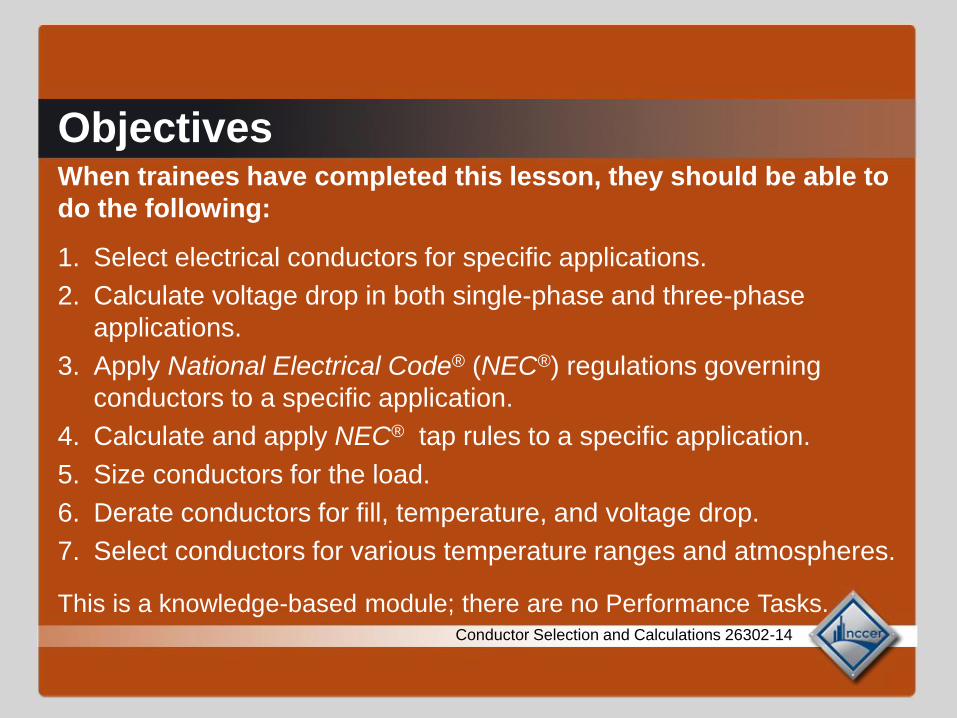
ObjectivesWhen trainees have completed this lesson, they should be able to
do the following:
1. Select electrical conductors for specific applications.
2. Calculate voltage drop in both single-phase and three-phase
applications.
3. Apply National Electrical Code® (NEC®) regulations governing
conductors to a specific application.
4. Calculate and apply NEC® tap rules to a specific application.
5. Size conductors for the load.
6. Derate conductors for fill, temperature, and voltage drop.
7. Select conductors for various temperature ranges and atmospheres.
This is a knowledge-based module; there are no Performance Tasks.Conductor Selection and Calculations 26302-14
1.0.0
Conductor Selection and Calculations 26302-14
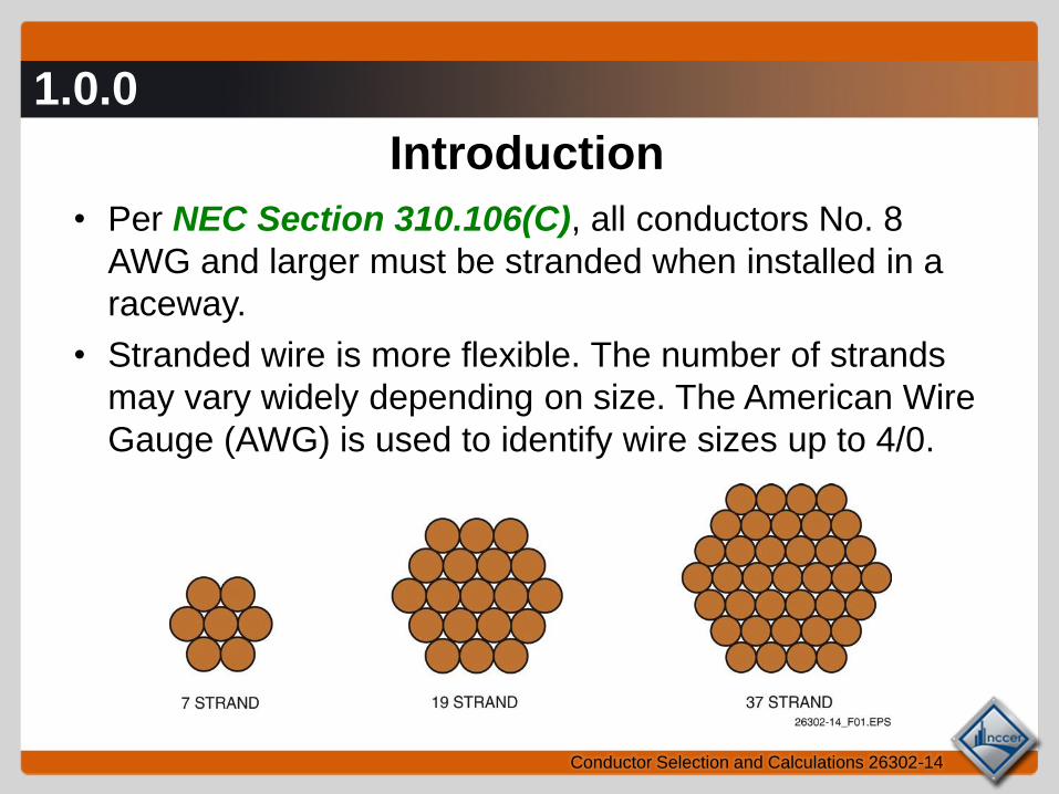
Introduction
• Per NEC Section 310.106(C), all conductors No. 8
AWG and larger must be stranded when installed in a
raceway.
• Stranded wire is more flexible. The number of strands
may vary widely depending on size. The American Wire
Gauge (AWG) is used to identify wire sizes up to 4/0.
1.0.0
Conductor Selection and Calculations 26302-14
Comparison of Various Wire Sizes
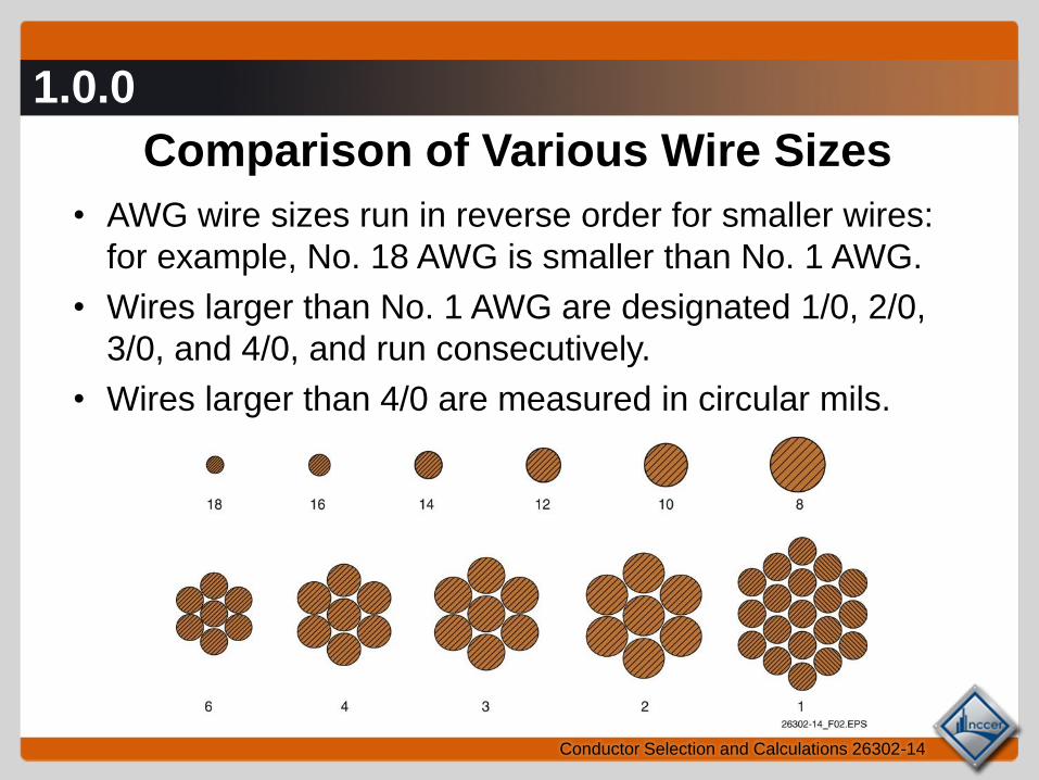
• AWG wire sizes run in reverse order for smaller wires:
for example, No. 18 AWG is smaller than No. 1 AWG.
• Wires larger than No. 1 AWG are designated 1/0, 2/0,
3/0, and 4/0, and run consecutively.
• Wires larger than 4/0 are measured in circular mils.
1.1.0
Conductor Selection and Calculations 26302-14
Compact Conductors
• Compact conductors have
been compressed to reduce
the air space between the
strands.
• This reduces the overall
diameter of the cable and
can be useful when
increasing the service or
feeder ampacity of the cable
in existing conduit.
Next Session…
Conductor Applications
2.0.0 – 2.1.0
Conductor Selection and Calculations 26302-14
Conductor Applications
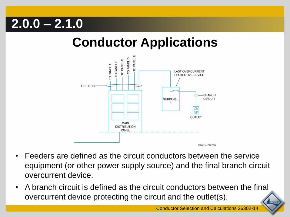
• Feeders are defined as the circuit conductors between the service
equipment (or other power supply source) and the final branch circuit
overcurrent device.
• A branch circuit is defined as the circuit conductors between the final
overcurrent device protecting the circuit and the outlet(s).
2.0.0 – 2.1.0
Conductor Selection and Calculations 26302-14
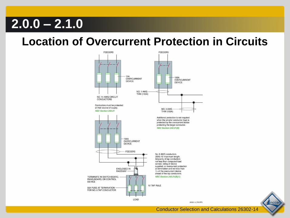
Location of Overcurrent Protection in Circuits
2.0.0 – 2.1.0
Conductor Selection and Calculations 26302-14
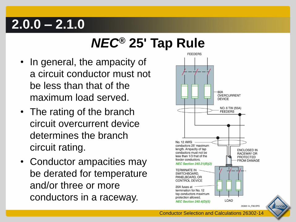
NEC® 25' Tap Rule
• In general, the ampacity of
a circuit conductor must not
be less than that of the
maximum load served.
• The rating of the branch
circuit overcurrent device
determines the branch
circuit rating.
• Conductor ampacities may
be derated for temperature
and/or three or more
conductors in a raceway.
2.0.0 – 2.1.0
Conductor Selection and Calculations 26302-14
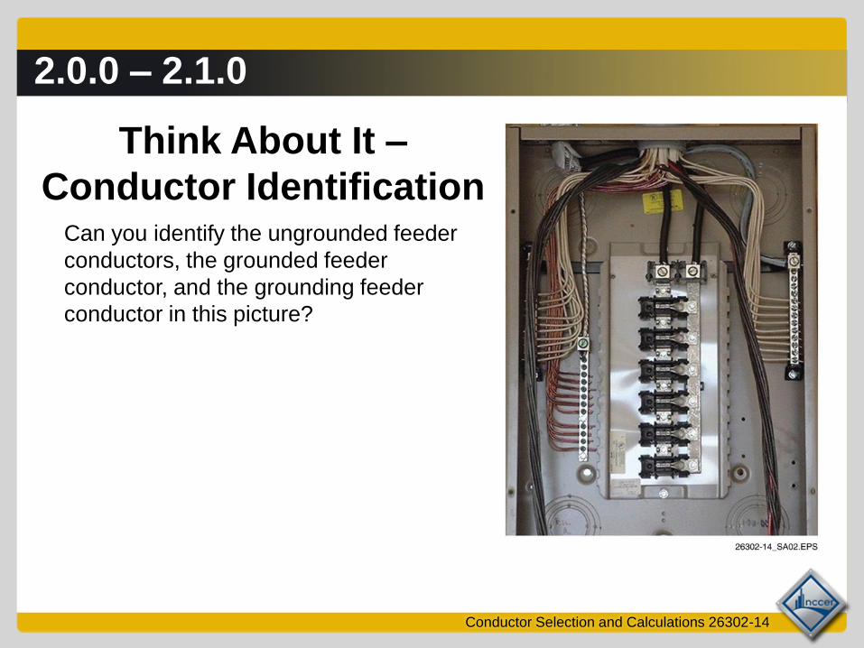
Think About It –
Conductor Identification Can you identify the ungrounded feeder
conductors, the grounded feeder
conductor, and the grounding feeder
conductor in this picture?

2.2.0 – 2.2.1
Conductor Selection and Calculations 26302-14
Conductor Protection
• Physical protection of conductors involves the proper
installation of conduit, boxes, fittings, and terminations.
• Electrical protection is provided by overcurrent protective
devices. When a noncurrent-limiting device is used for
short circuit protection, the conductor’s short circuit
withstand rating must be selected based on the device’s
ability to protect the circuit.
2.2.0 – 2.2.1
Conductor Selection and Calculations 26302-14
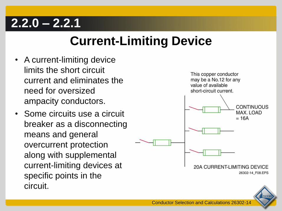
Current-Limiting Device
• A current-limiting device
limits the short circuit
current and eliminates the
need for oversized
ampacity conductors.
• Some circuits use a circuit
breaker as a disconnecting
means and general
overcurrent protection
along with supplemental
current-limiting devices at
specific points in the
circuit.
2.2.0 – 2.2.1
Conductor Selection and Calculations 26302-14
Think About It –
Location of Overcurrent Protection Is overcurrent protection required for the secondary conductors at the
transformer terminals shown here?
Next Session…
Properties of Conductors
5.0.0 – 6.0.0
Conductor Selection and Calculations 26302-14
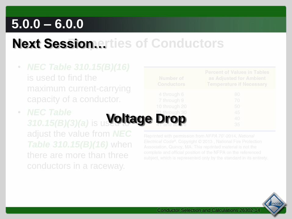
Properties of Conductors
• NEC Table 310.15(B)(16)
is used to find the
maximum current-carrying
capacity of a conductor.
• NEC Table
310.15(B)(3)(a) is used to
adjust the value from NEC
Table 310.15(B)(16) when
there are more than three
conductors in a raceway.
Next Session…
Voltage Drop
4.0.0 – 4.3.0
Conductor Selection and Calculations 26302-14
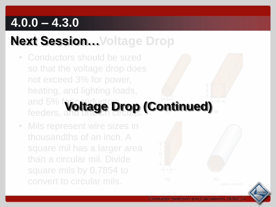
Voltage Drop
• Conductors should be sized
so that the voltage drop does
not exceed 3% for power,
heating, and lighting loads,
and 5% for conductors,
feeders, and branch circuits.
• Mils represent wire sizes in
thousandths of an inch. A
square mil has a larger area
than a circular mil. Divide
square mils by 0.7854 to
convert to circular mils.
Next Session…
Voltage Drop (Continued)
4.4.0 – 4.5.1
Conductor Selection and Calculations 26302-14
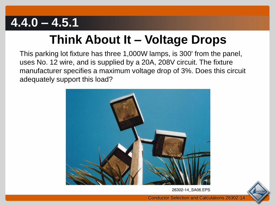
Think About It – Voltage DropsThis parking lot fixture has three 1,000W lamps, is 300' from the panel,
uses No. 12 wire, and is supplied by a 20A, 208V circuit. The fixture
manufacturer specifies a maximum voltage drop of 3%. Does this circuit
adequately support this load?
4.4.0 – 4.5.1
Conductor Selection and Calculations 26302-14
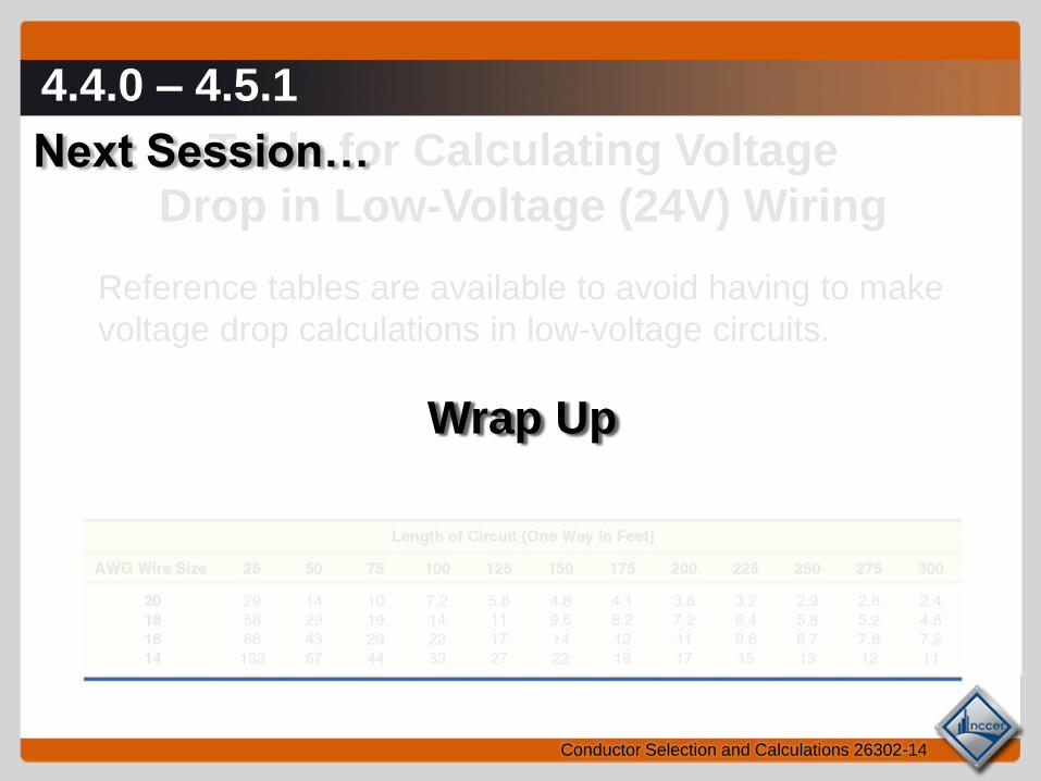
Table for Calculating Voltage
Drop in Low-Voltage (24V) Wiring
Reference tables are available to avoid having to make
voltage drop calculations in low-voltage circuits.
Next Session…
Wrap Up
Wrap Up
– Write important things learned during class
– Write questions you have about the material
– Write thought you had about the material
Conductor Selection and Calculations 26302-14

Next Session…
MODULE EXAM
Review the complete module to prepare
for the module exam. Complete the Module
Review as a study aid.
Conductor Selection and Calculations 26302-14


![Level 2 Diploma in Auto Electrical and Mobile Electrical ... · City & Guilds Level 2 Diploma in Auto Electrical and Mobile Electrical Principles (4290[62])- 3 Contents 1 Introduction](https://img.pdfslide.net/doc/110x75/5b2fc3d37f8b9ae16e8d9655/level-2-diploma-in-auto-electrical-and-mobile-electrical-city-guilds-level.jpg)