Embed Size (px)
Citation preview
Electrical Machines IIWeek 8: Induction motor tests, Maximum power, maximum torque and
maximum efficiency criterion
Determination of motor parameters
Due to the similarity between the induction motor equivalent circuit and the
transformer equivalent circuit, same tests are used to determine the values
of the motor parameters.
DC test: determine the stator resistance Rs
No-load test: determine the rotational losses and magnetization current (similar to no-
load test in Transformers).
Locked-rotor test: determine the rotor and stator impedances (similar to short-circuit test
in Transformers).

DC test The purpose of the DC test is to determine Rs. A variable DC voltage source is connected between two stator
terminals.
The DC source is adjusted to provide approximately rated stator current, and the resistance between the two
stator leads is determined from the voltmeter and ammeter readings.
If the stator is Y-connected, the per phase stator resistance
is
If the stator is delta-connected, the per phase stator
resistance is
DCDC
DC
VR
I
12
DCRR
1
3
2DCR R
The measured value of the resistance may be multiplied by a factor ranging from
1.05 to 1.25 in order to convert it from its dc value to its ac value. This is done to
account for the skin effect.
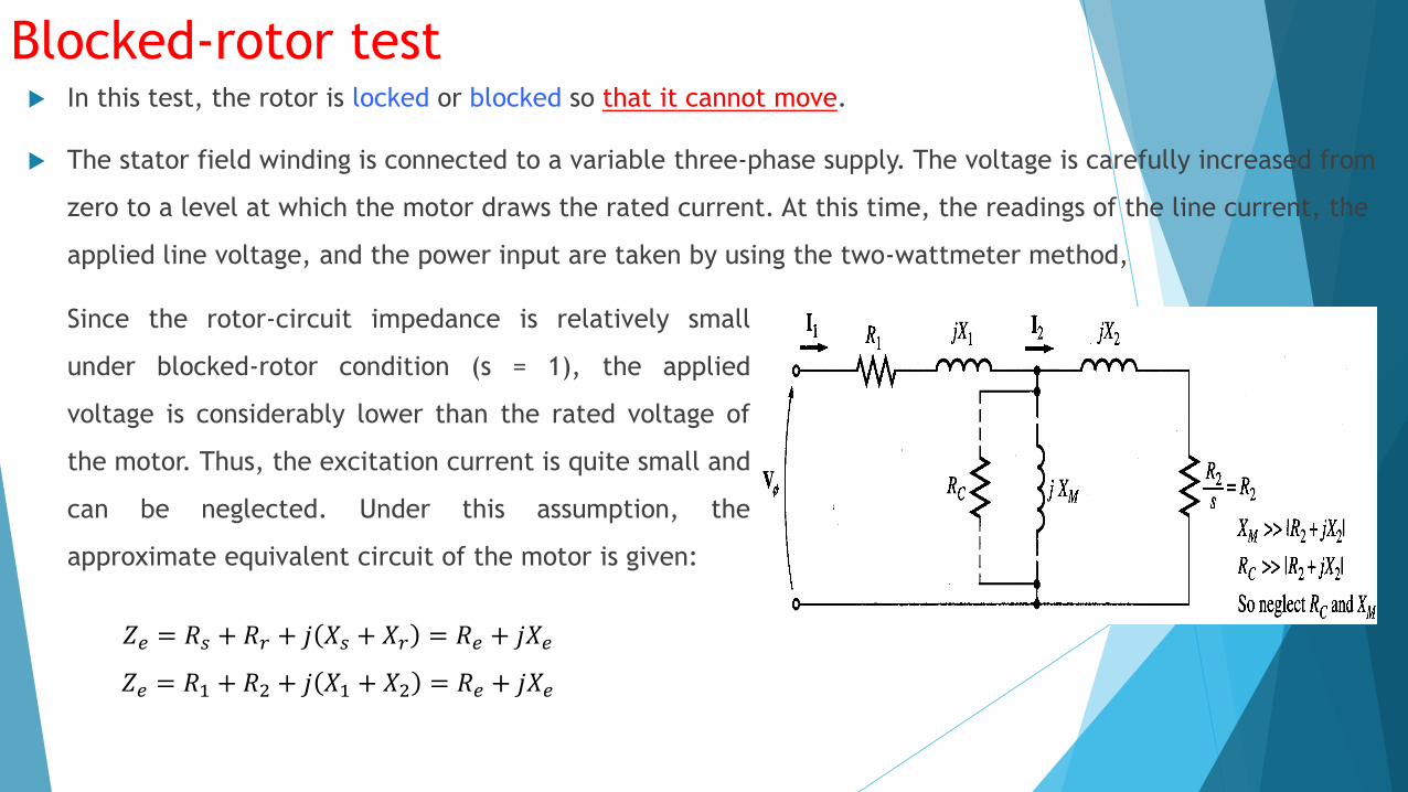
Blocked-rotor test In this test, the rotor is locked or blocked so that it cannot move.
The stator field winding is connected to a variable three-phase supply. The voltage is carefully increased from
zero to a level at which the motor draws the rated current. At this time, the readings of the line current, the
applied line voltage, and the power input are taken by using the two-wattmeter method,
Since the rotor-circuit impedance is relatively small
under blocked-rotor condition (s = 1), the applied
voltage is considerably lower than the rated voltage of
the motor. Thus, the excitation current is quite small and
can be neglected. Under this assumption, the
approximate equivalent circuit of the motor is given:
𝑍𝑒 = 𝑅𝑠 + 𝑅𝑟 + 𝑗 𝑋𝑠 + 𝑋𝑟 = 𝑅𝑒 + 𝑗𝑋𝑒
𝑍𝑒 = 𝑅1 + 𝑅2 + 𝑗 𝑋1 + 𝑋2 = 𝑅𝑒 + 𝑗𝑋𝑒

Blocked-rotor testSince 𝑅𝑠 is already known from the stator-resistance test, the
equivalent rotor resistance is
𝑅𝑟 = 𝑅2 = 𝑅𝑒 − 𝑅𝑠
However,
𝑍𝑏𝑟 =𝑉𝑏𝑟𝐼𝑏𝑟
Therefore,
𝑋𝑒 = 𝑍𝑏𝑟2 − 𝑅𝑒
2
It is rather difficult to isolate the leakage reactances 𝑋1 and 𝑋2. For all practical purposes, these reactances
are usually assumed to be equal. That is
𝑋1 = 𝑋2 = 0.5𝑋𝑒

No-load test
In this case the rated voltage is impressed upon the stator windings and the motor operates freely
without any load. This test, therefore, is similar to the open-circuit test on the transformer except that
friction and windage loss is associated with an induction motor.
Since the slip is nearly zero, the impedance of the rotor circuit is almost infinite. The per-phase
approximate equivalent circuit of the motor with the rotor circuit open is shown.

In order to represent the core loss by an equivalent resistance 𝑅𝑐 we must subtract the friction and
windage loss from the power input. The friction and windage loss can be measured by coupling the
motor under test to another motor with a calibrated output and running it at the no-load speed of the
induction motor. Let 𝑃𝑓𝑤𝜑 be the friction and windage loss on a per-phase basis. Then, the power loss in
𝑅𝑐, is:
No-load test
𝑃𝑜𝑐 = 𝑊𝑜𝑐 − 𝑃𝑓𝑤𝜑
Hence, the core-loss resistance is
𝑅𝑐 =𝑉𝑜𝑐2
𝑃𝑜𝑐The power factor under no load is
cos𝜑𝑜𝑐 =𝑊𝑜𝑐
𝑉𝑜𝑐𝐼𝑜𝑐
The magnetization reactance is
Type equation here.Type equation here.
𝑋𝑚 =𝑉𝑜𝑐
𝐼𝑜𝑐 sin 𝜃𝑜𝑐
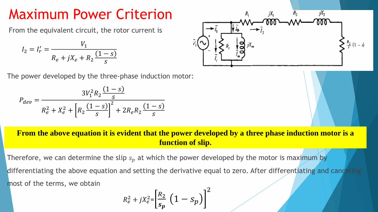
Maximum Power CriterionFrom the equivalent circuit, the rotor current is
𝐼2 = 𝐼𝑟′ =
𝑉1
𝑅𝑒 + 𝑗𝑋𝑒 + 𝑅21 − 𝑠𝑠
The power developed by the three-phase induction motor:
𝑃𝑑𝑒𝑣 =3𝑉1
2𝑅21 − 𝑠𝑠
𝑅𝑒2 + 𝑋𝑒
2 + 𝑅21 − 𝑠𝑠
2
+ 2𝑅𝑒𝑅21 − 𝑠𝑠
From the above equation it is evident that the power developed by a three phase induction motor is a
function of slip.
Therefore, we can determine the slip 𝑠𝑝 at which the power developed by the motor is maximum by
differentiating the above equation and setting the derivative equal to zero. After differentiating and canceling
most of the terms, we obtain
𝑅𝑒2 + 𝑗𝑋𝑒
2=𝑅2
𝒔𝒑1 − 𝑠𝑝
2
Maximum Power Criterion
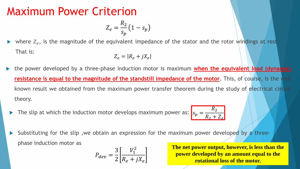
𝑍𝑒 =𝑅2𝑠𝑝
1 − 𝑠𝑝
where 𝑍𝑒, is the magnitude of the equivalent impedance of the stator and the rotor windings at rest.
That is:𝑍𝑒 = 𝑅𝑒 + 𝑗𝑋𝑒
the power developed by a three-phase induction motor is maximum when the equivalent load (dynamic)
resistance is equal to the magnitude of the standstill impedance of the motor. This, of course, is the well
known result we obtained from the maximum power transfer theorem during the study of electrical circuit
theory.
The slip at which the induction motor develops maximum power as: 𝑠𝑝 =𝑅2
𝑅2 + 𝑍𝑒
Substituting for the slip ,we obtain an expression for the maximum power developed by a three-
phase induction motor as
𝑃𝑑𝑒𝑣 =3
2
𝑉12
𝑅𝑒 + 𝑗𝑋𝑒
The net power output, however, is less than the
power developed by an amount equal to the
rotational loss of the motor.
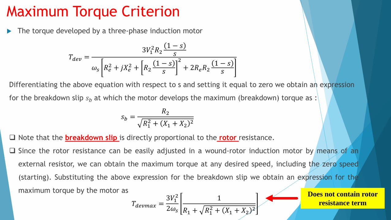
Maximum Torque Criterion The torque developed by a three-phase induction motor
𝑇𝑑𝑒𝑣 =3𝑉1
2𝑅21 − 𝑠𝑠
𝜔𝑠 𝑅𝑒2 + 𝑗𝑋𝑒
2 + 𝑅21 − 𝑠𝑠
2
+ 2𝑅𝑒𝑅21 − 𝑠𝑠
Differentiating the above equation with respect to s and setting it equal to zero we obtain an expression
for the breakdown slip 𝑠𝑏 at which the motor develops the maximum (breakdown) torque as :
𝑠𝑏 =𝑅2
𝑅12 + 𝑋1 + 𝑋2
2
Note that the breakdown slip is directly proportional to the rotor resistance.
Since the rotor resistance can be easily adjusted in a wound-rotor induction motor by means of an
external resistor, we can obtain the maximum torque at any desired speed, including the zero speed
(starting). Substituting the above expression for the breakdown slip we obtain an expression for the
maximum torque by the motor as
𝑇𝑑𝑒𝑣𝑚𝑎𝑥 =3𝑉1
2
2𝜔𝑠
1
𝑅1 + 𝑅12 + 𝑋1 + 𝑋2
2
Does not contain rotor
resistance term

Maximum Torque CriterionNote that the maximum torque developed by the motor is independent of the rotor
resistance. In other words, the motor develops the same maximum torque regardless
of its rotor resistance. The rotor resistance affects only the breakdown slip (or
breakdown speed) at which the torque is maximum

Maximum Torque Criterion: Further Approximation
When the stator impedance is so small that it can be neglected in comparison with the rotor impedance
at standstill, we obtain a very useful expression for the breakdown slip as:
𝑠𝑏 =𝑅2𝑋2
This equation states that the breakdown slip is simply a ratio of rotor resistance to rotor reactance. When
the rotor resistance is made equal to the rotor reactance, the breakdown slip is unity. In this case, the motor
develops the maximum torque at starting. The approximate expression for the breakdown torque becomes:
𝑇𝑑𝑒𝑣𝑚𝑎𝑥 =3𝑉1
2
2𝜔𝑠
1
𝑋2=3𝑉1
2
2𝜔𝑠
𝑠𝑏𝑅2
The rotor current at any speed when the stator impedance is neglected is:
𝐼2 =𝑉1
𝑅2𝑠 + 𝑗𝑋2
𝑠𝑏 =𝑅2
𝑅12 + 𝑋1 + 𝑋2
2
stator impedance neglected
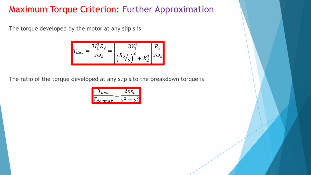
Maximum Torque Criterion: Further Approximation
The torque developed by the motor at any slip s is
𝑇𝑑𝑒𝑣 =3𝐼1
2𝑅2𝑠𝜔𝑠
=3𝑉1
2
𝑅2𝑠
2
+ 𝑋22
𝑅2𝑠𝜔𝑠
The ratio of the torque developed at any slip s to the breakdown torque is
𝑇𝑑𝑒𝑣𝑇𝑑𝑒𝑣𝑚𝑎𝑥
=2𝑠𝑠𝑏
𝑠2 + 𝑠𝑏2
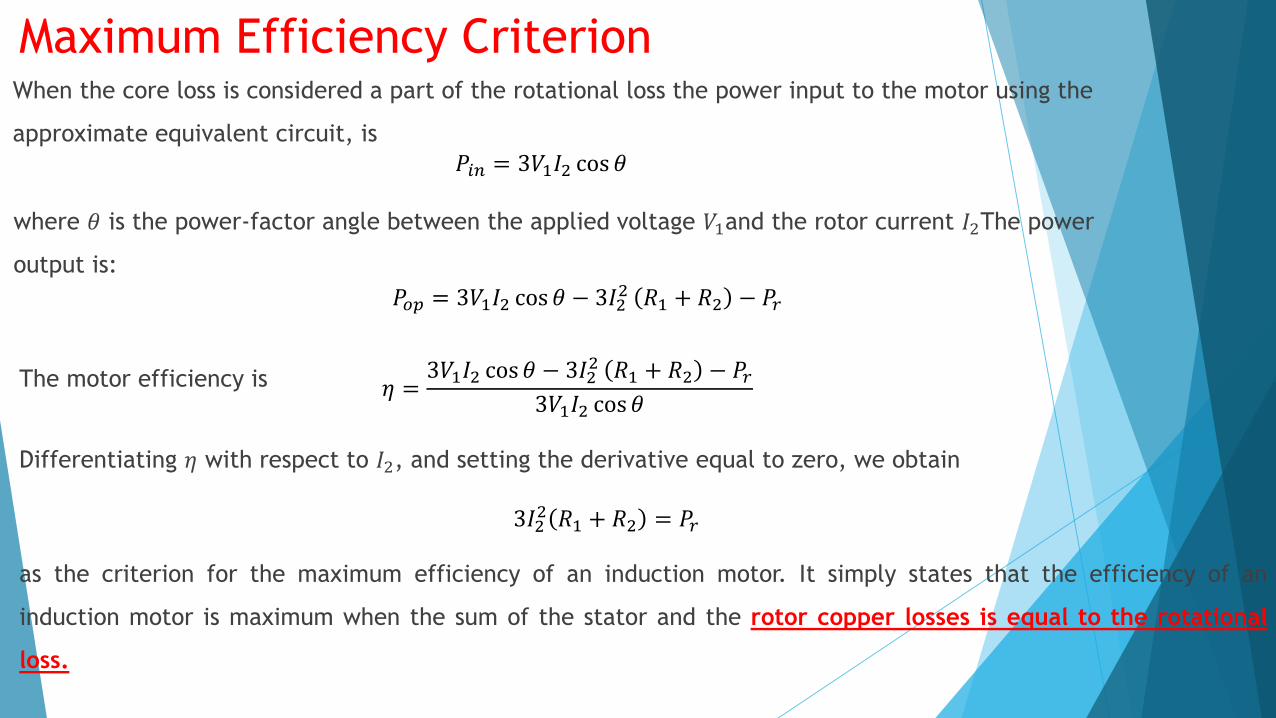
Maximum Efficiency CriterionWhen the core loss is considered a part of the rotational loss the power input to the motor using the
approximate equivalent circuit, is
𝑃𝑖𝑛 = 3𝑉1𝐼2 cos 𝜃
where 𝜃 is the power-factor angle between the applied voltage 𝑉1and the rotor current 𝐼2The power
output is:
𝑃𝑜𝑝 = 3𝑉1𝐼2 cos 𝜃 − 3𝐼22 𝑅1 + 𝑅2 − 𝑃𝑟
The motor efficiency is 𝜂 =3𝑉1𝐼2 cos 𝜃 − 3𝐼2
2 𝑅1 + 𝑅2 − 𝑃𝑟3𝑉1𝐼2 cos 𝜃
Differentiating 𝜂 with respect to 𝐼2, and setting the derivative equal to zero, we obtain
3𝐼22 𝑅1 + 𝑅2 = 𝑃𝑟
as the criterion for the maximum efficiency of an induction motor. It simply states that the efficiency of an
induction motor is maximum when the sum of the stator and the rotor copper losses is equal to the rotational
loss.

Torque – Speed Characteristics
m
outL
PT
s
RIPPT
s
rr
s
gap
m
devdev
'2'3
2
2'
2'3
lrlsr
s
s
s
re
XXs
RR
V
s
RT
Substituting for Ir’ from the equivalent circuit:
The equation reveals that the torque developed by an induction motor is directly proportional to the square of the current in
the rotor circuit and the equivalent hypothetical resistance of the rotor.
However, the two quantities, the rotor current and the hypothetical rotor resistance, are inversely related to each other.
For instance, if the rotor resistance is increased, we expect the torque developed by the motor to increase linearly. But any
increase in the rotor resistance is accompanied by a decrease in the rotor current for the same induced emf in the rotor.
A decrease in the rotor current causes a reduction in the torque developed. Whether the overall torque developed increases or
decreases depends upon which parameter plays a dominant role.
𝑅𝑟 ⇑, 𝐼𝑟 ⇓ 𝑎𝑡 𝑡ℎ𝑒 𝑠𝑎𝑚𝑒 𝑟𝑜𝑡𝑜𝑟 𝑒𝑚𝑓, 𝑇𝑑𝑒𝑣 ⇓

Torque – Speed Characteristics
At standstill, the rotor slip is unity (s=1) and the effective rotor resistance is 𝑅𝑟′ ,. The magnitude of the rotor current is:
'
1'
r
rX
EI
per-phase exact equivalent circuit of a
balanced three-phase induction motor
Note that the rotor winding resistance 𝑅𝑟′ , is usually very small compared
with its leakage reactance 𝑿𝒓′ ,. That is, 𝑅𝑟
′ , <<𝑋𝑟′
The starting torque developed by the motor is:
s
rrstart
RIT
'2'3
As the rotor starts rotating, an increase in its speed is accompanied by a decrease in its slip. As 𝑠 decreases, speed
increases. As long as 𝑹𝒓′
𝒔 is smaller than 𝑿𝒓′ , the reduction in the rotor current is minimal. Thus, in this speed range,
the rotor current may be approximated as
2'2'
1'
rr
r
XR
EI
At start, rotor speed
is 0, slip is 1
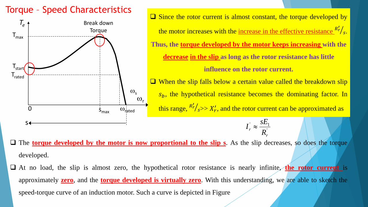
Torque – Speed Characteristics Since the rotor current is almost constant, the torque developed by
the motor increases with the increase in the effective resistance 𝑅𝑟′
𝑠.
Thus, the torque developed by the motor keeps increasing with the
decrease in the slip as long as the rotor resistance has little
influence on the rotor current.
When the slip falls below a certain value called the breakdown slip
𝑠𝑏, the hypothetical resistance becomes the dominating factor. In
this range, 𝑅𝑟′
𝑠>> 𝑋𝑟′ , and the rotor current can be approximated as
'
1'
r
rR
sEI
The torque developed by the motor is now proportional to the slip s. As the slip decreases, so does the torque
developed.
At no load, the slip is almost zero, the hypothetical rotor resistance is nearly infinite, the rotor current is
approximately zero, and the torque developed is virtually zero. With this understanding, we are able to sketch the
speed-torque curve of an induction motor. Such a curve is depicted in Figure
r
s
Trated
Break down Torque
Te
0 ratedsmax
Tstart
Tmax
s