Embed Size (px)
Citation preview
6/12/2012
1
1
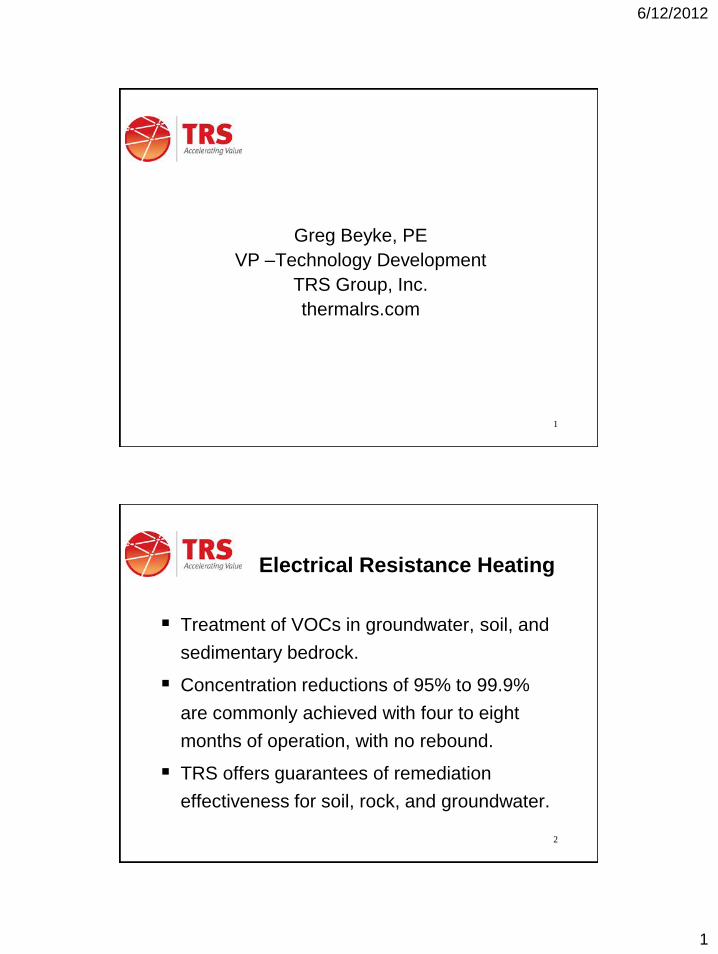
Greg Beyke, PE
VP –Technology Development
TRS Group, Inc.
thermalrs.com
2
Electrical Resistance Heating
Treatment of VOCs in groundwater, soil, and
sedimentary bedrock.
Concentration reductions of 95% to 99.9%
are commonly achieved with four to eight
months of operation, with no rebound.
TRS offers guarantees of remediation
effectiveness for soil, rock, and groundwater.
6/12/2012
2
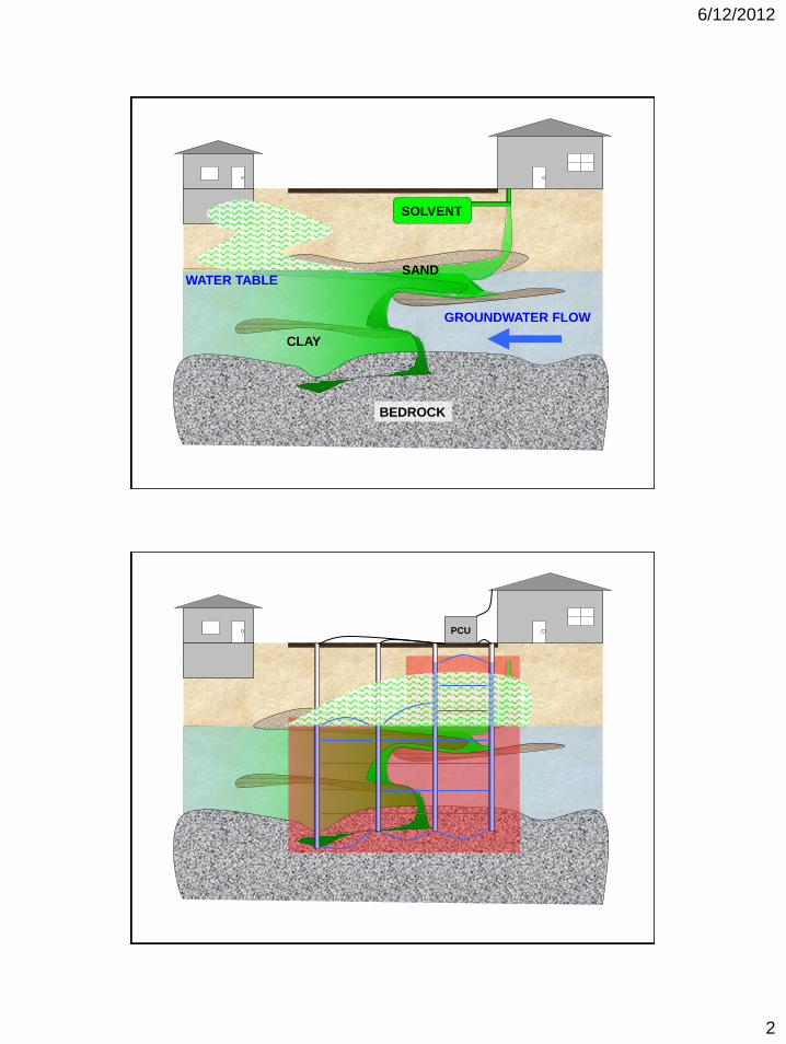
SOLVENT
SAND
CLAY
BEDROCK
WATER TABLE
GROUNDWATER FLOW
PCU

6/12/2012
3
GAC
Filter
Sheet piles
Angled
Horizontal
Electrode
Types

6/12/2012
4
7
ERH Surface
Equipment
Steam Condenser
500 kW PCU
Operating
Electrode
Photo
Courtesy of
Brown and
Caldwell
8
Why Electrical
Resistance Heating?
Steam is produced in-situ
Heating is uniform with no bypassed regions
Equally effective in the vadose, saturated
zone, and sedimentary bedrock
Heating is rapid yet gentle
No soil desiccation
Preferentially heats tight soil lenses and
DNAPL hot spots
6/12/2012
5
9
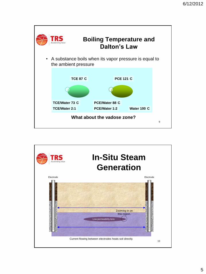
Boiling Temperature and
Dalton’s Law
• A substance boils when its vapor pressure is equal to
the ambient pressure
TCE 87 C PCE 121 C
Water 100 C
TCE/Water 73 C PCE/Water 88 C
TCE/Water 2:1 PCE/Water 1:2
What about the vadose zone?
10
In-Situ Steam
Generation
Low permeability lens
Electrode Electrode
Current flowing between electrodes heats soil directly.
Zooming in on
this region.

6/12/2012
6
11
In-Situ Steam
Generation
Low permeability lens
Reductive dehalogenation creates a “halo” of chloride ions in CVOC hot spots
DNAPL
12
In-Situ Steam
Generation
Uniform soils would lead to parallel ERH current lines – but soils aren’t uniform.

6/12/2012
7
13
In-Situ Steam
Generation
Low permeability lenses and CVOC hot spots attract current.
14
In-Situ Steam
Generation
Steam bubbles form more quickly at NAPL due to interfacial tension and reduced
boiling temperatures. Typically form 500-1000 pore volumes of steam in situ.
Regions with higher current
density heat slightly more quickly.

6/12/2012
8
TRS Patented Adaptive Electrode
TRS backfill contains
zero valent iron (ZVI)
CVOC – ZVI reaction produces
conductive chloride ions
DNAPL or
high CVOC
concentrations
Automatically
boosts power
in CVOC
regions
16
Why Electrical
Resistance Heating?
Because steam is produced in-situ, ERH is more
tolerant of heterogeneity than any other remediation
technology.
It doesn’t matter if:
The subsurface is clay
The subsurface is gravel
The subsurface is interbedded clay and gravel
The subsurface is vadose, perched water, or saturated

6/12/2012
9
17
Heating Weaknesses
• Peat or high organic carbon – granular activated
carbon is used to adsorb VOCs because of the
bonding between them*
• Oil or grease as a co-contaminant (Raoult’s Law)*
• “Pancake sites” (big area, thin depth) – minimum 10ft
treatment interval
• Fuel sites – other options and tend to be pancakes
ERH Weaknesses
• Landfills – ERH is more uniform in natural materials
• Fractured igneous rock – no experience yet
• ERH chases CVOC contamination (strength?)
* Weakness shared with other in situ technologies.
18
Reasons to Heat Low
Volatility NAPLs
Reduce NAPL viscosity
Reduce NAPL specific gravity – change
DNAPL to LNAPL
Steam bubble floatation
Thermally enhanced bioremediation polish
Strip out the more volatile and toxic
components, leaving an inert and non-mobile
soil particle stain
6/12/2012
10
19
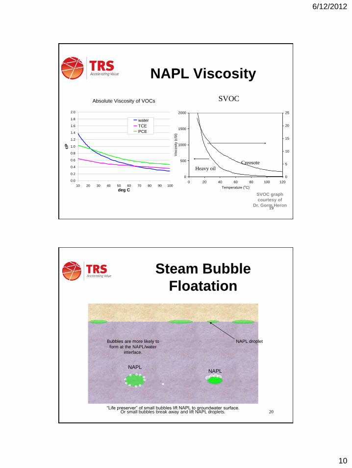
NAPL Viscosity
0
500
1000
1500
2000
0 20 40 60 80 100 120
Temperature (oC)
Vis
cosity (
cS
t)0
5
10
15
20
25
Creosote Heavy oil
SVOC
SVOC graph
courtesy of
Dr. Gorm Heron
Absolute Viscosity of VOCs
0.0
0.2
0.4
0.6
0.8
1.0
1.2
1.4
1.6
1.8
2.0
10 20 30 40 50 60 70 80 90 100
deg C
cP
water
TCE
PCE
20
Steam Bubble
Floatation
“Life preserver” of small bubbles lift NAPL to groundwater surface.
NAPL NAPL
Or small bubbles break away and lift NAPL droplets.
Bubbles are more likely to
form at the NAPL/water
interface.
NAPL droplet
6/12/2012
11
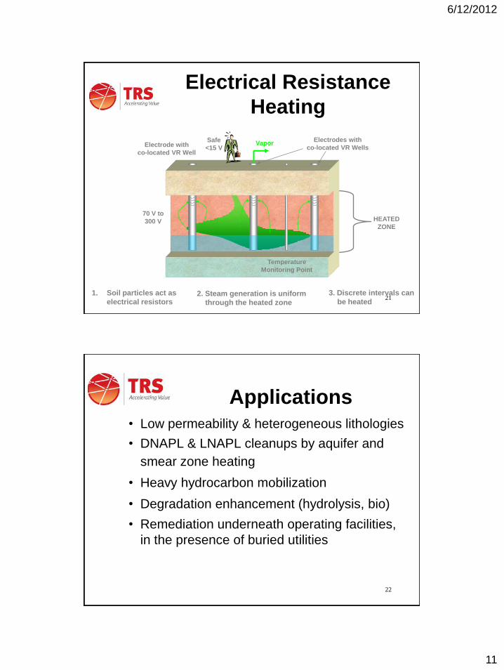
21
Electrical Resistance
Heating
HEATED
ZONE
Electrodes with
co-located VR Wells
2. Steam generation is uniform
through the heated zone
1. Soil particles act as
electrical resistors
70 V to
300 V
Safe
<15 V
3. Discrete intervals can
be heated
Electrode with
co-located VR Well
Temperature
Monitoring Point
Vapor
22
Applications
• Low permeability & heterogeneous lithologies
• DNAPL & LNAPL cleanups by aquifer and
smear zone heating
• Heavy hydrocarbon mobilization
• Degradation enhancement (hydrolysis, bio)
• Remediation underneath operating facilities,
in the presence of buried utilities

6/12/2012
12
23
Dry Cleaner – Fair
Lawn, NJ
• PCE in Soil, Sandstone, and Groundwater
• Treatment area 6000 ft2, depth 0.5 to 26-ft
bgs, 5,000 yd3
• Glacial till with fractured sandstone bedrock
at 16 ft bgs
• GAC for vapor treatment
• Baseline: Up to 288 mg/kg PCE in soil
• Remedial goal: PCE <1 mg/kg in soil
Insulating Cover

6/12/2012
13
25
Average Temperatures
during Heat-up Avg Temp
Nearby Mixed Soil and Bedrock Site
-30
-25
-20
-15
-10
-5
0
10 20 30 40 50 60 70 80 90 100 110
Temperature (C)
Dep
th (
bg
s)
9/14/07
9/21/07
9/28/07
10/5/07
Sed
imen
tary
Bed
rock
So
il (
silt
y s
an
d)
PCE Concentration in Soil
26
99.95% Reduction

6/12/2012
14
PCE in Groundwater
27
Coming Attraction –
Edgemere, NY
28

6/12/2012
15
Coming Attraction II –
Newtown, CT
29
30
Polishing
Mechanisms
• Hydrolysis of Halogenated Alkanes
– Compounds such as TCA have a hydrolysis half-life of less than one day at
steam temperatures.
• Iron Reductive Dehalogenation
– Steel shot used as electrode backfill provides an iron source for reductive
dehalogenation (iron filing wall)
• Temperature Accelerates Reactions
– The above reaction rates are increased by factor of thousands at 100°C
(Arrhenius Equation)
• Bioremediation by Thermophiles
– Dehalogenating bacteria Dehalobacter, Desulfuromonas, and
Desulfotomaculum prefer 40-80°C
– Dehalogenating bacteria Dehalococcoides prefer 30°C

6/12/2012
16
31
Hydrolysis Water Substitution Reaction Hydrolysis Rates of Selected Halogenated Alkanes
0.01
0.10
1.00
10.00
100.00
40 50 60 70 80 90 100 110 120
Temperature (°C)
hyd
roly
sis
ha
lf-l
ife a
t p
H 7
(d
ay
s)
methylene chloride
1,2-DCA
1,1-DCA
carbon tetrachloride
EDB
1,3 dichloropropane
1,1,2,2 TeCA
1,1,1-TCA
32
Microbe Counts Average of Three Wells
1.0E+04
1.0E+05
1.0E+06
1.0E+07
1.0E+08
1.0E+09
heterotrophic (all microbes)
@ 8-10 ft
petrophilic (hydrocarbon
degrading) @ 8-10 ft
heterotrophic (all microbes)
@ 12-14 ft
petrophilic (hydrocarbon
degrading) @ 12-14 ft
prior to ERH
1 day after ERH
3 months after ERH
10x increase
100x increase
5x increase
46x increase
6/12/2012
17
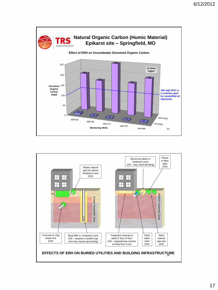
33
Natural Organic Carbon (Humic Material)
Epikarst site – Springfield, MO
MW B2MW B5
MW C4MW E5
average
pre-ERH
post-ERH
190
160
250
160
190
8
34
35
0
50
100
150
200
250
Dissolved
Organic
Carbon
(mg/l)
Monitoring Wells
Effect of ERH on Groundwater Dissolved Organic Carbon
41 times
higher
100 mg/l DOC is
a common goal
for emulsified oil
injections.
34
>5’
Dee
pe
r Tre
atm
en
t Zo
ne
Plastic natural
gas line above
treatment zone
(OK)
Concrete or clay
sewer line
(OK)
Steel MW in treatment zone
(OK - requires a sealed cap
and may require grounding)
Treatment extends to
within 2 feet of floor
(OK - engineering controls
to keep floor cool)
Steel
water
main
(OK)
Electrical cables in
treatment zone
(OK - may need derating)
Phone
or fiber
optic
(OK)
Steel
natural
gas line
(OK)
EFFECTS OF ERH ON BURIED UTILITIES AND BUILDING INFRASTRUCTURE
Sh
allo
w T
rea
tme
nt Z
on
e

6/12/2012
18
35
Electrical Resistance Heating uniformly heats the subsurface and
removes VOCs from all soil types, both above and below the
water table. Good for your “tough sites”.
Questions?
Greg Beyke
Thermal Remediation Services
(615) 791-5772
thermalrs.com