Embed Size (px)
Citation preview
1/2017 | MONITORMONITOR |
MAGAZINE FOR ELECTRICAL SAFETY
17
1
Electrical safety for mobile generators
New trend for machines: Signalling instead of switching
isoGEN523:
Insulation monitoring for mobile generators
Additional page "Practical Expertise" at the back of the booklet for collection!
What you should know about measuring current transformers
"P"
NEW
| MONITORMONITOR | 1/201702
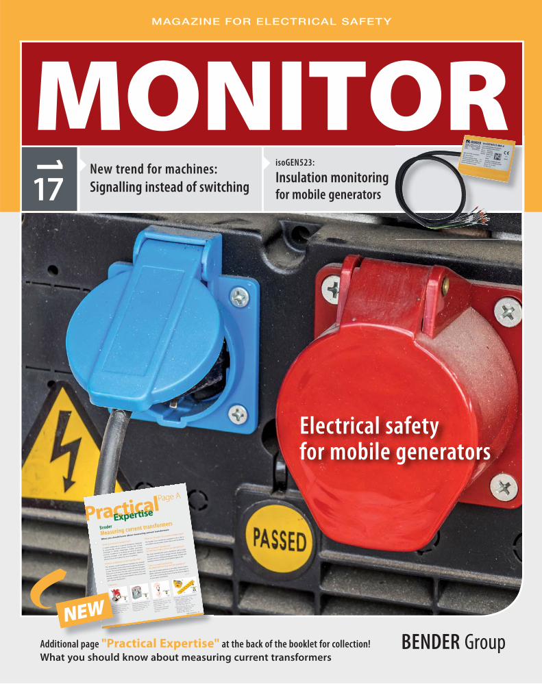
Dear Readers,
editorial
Bender GmbH & Co. KG. Londorfer Straße 65 35305 Gruenberg /GermanyFon: +49 6401 807 - 0 Fax: +49 6401 807 - 259 E-Mail: [email protected] www.bender.de
Editorial staff: Marita Schwarz-Bierbach,Anne Katrin Römer
Graphic & layout: Natascha Schäfer, www.s-designment.netCopy-editing/text: Michaela Heck M.A., Textwerk
Photos: Bender Archiv, S!Designment Archiv, LEAG_DE, Rainer Weisfl og (LEAG), Christian Bedeschinsky (LEAG), Markus Scholand, E. Wiesenhütter, VDE_DLG, Freiwillige Feuerwehr der Stadt Goch/www.feuerwehr-goch.de, Forum Elektromobilität, Bender UK, Easychrage.me GmbH, Sync R & DMalaysia, Eetarp Engineering Malaysia, Moto Engineering Foundation Spanien, Elteco Norwegen, TÜV Süd, Dahms GmbH, Krankenhausgesellschaft St. Vincenz, Wolfgang Pehlemann [CC BY-SA 3.0 de (http://creativecommons.org/licenses/by-sa/3.0/de/deed.en)], via Wikimedia CommonsFotolia: pressmaster, potowizard, MABO, Andrei MerkuloviStock: onurdongel 123RF: stefan77, Milos Stojanovic, Olga SerdyukAdobeStock: SV PRODUCTION, bildlove, Sergey NivensGettyImages: Chris Knapton
Print: Druckhaus Bechstein, Wetzlar
E D I T O R I A L
SUBSCRIPTION
Would you like to receive a print version of the MONITOR twice a year and free of charge?
Please use the link www.bender.de/monitor-abo or scan the code. .
IMPRINT
Sabine Bender-Suhr CFO
Solutions for electrical safety are also the subject of this issue of our customer mag-
azine, MONITOR. We are pleased to present a wide range of news from the fi elds
of technology, standardisation and solutions as well as new products. At the same
time the date of publication of this edition is also associated with events of particular
importance for our company:
As of 3rd April 2017, Markus Schyboll assumed the chairmanship of the Executive
Board (CEO). He succeeds Dr Dirk Pieler, who successfully led the company from
2009 to 2016. Markus Schyboll has achieved an impressive, internationally oriented
career. Along the way he has proven his ability to successfully lead the development
of business strategies and their strategic, step-by-step and intelligent implementa-
tion. The focus of his activities will be to assess our business activities from the
stringent perspective of the current and future market requirements on a regular
basis, to identify opportunities to align the operation to the current requirements
and to create new structures. Which is why, dear readers, we would like to ask you
to exchange with us as closely as before.
The Hannover Messe, as the leading international trade fair of modern industry,
not only offers Markus Schyboll a stage for his fi rst international appearance with
Bender; we'll present the web-based software solution POWERSCOUT® for the
fi rst time in Hanover. One of the applications is the periodic verifi cation pursuant to
DGUV regulation 3 (German Social Accident Insurance regulation 3), which, thanks
to Bender technology, can be carried out during ongoing operation and offers a
major advantage in terms of safety.
In March, POWERSCOUT® received the 'BEST OF' award as part of the IT Innovation
Award in the category of Cloud Computing: “The early detection of faults, removal
of disruptions and targeted maintenance result not only in high system availability
and maintenance team relief, they also help avoid costs and ensure competitive-
ness,” according to an excerpt from the statement of the jury.
Innovation and growth at Bender will also be experienced through our locations
in 2017. In this issue we report on the new premises of our subsidiary Bender UK
(England) and in the next issue on the completion of extensive construction work at
the company headquarters in Grünberg.
We hope you will enjoy reading this issue!
Yours
1/2017 | MONITORMONITOR |
content
03
C O N T E N T
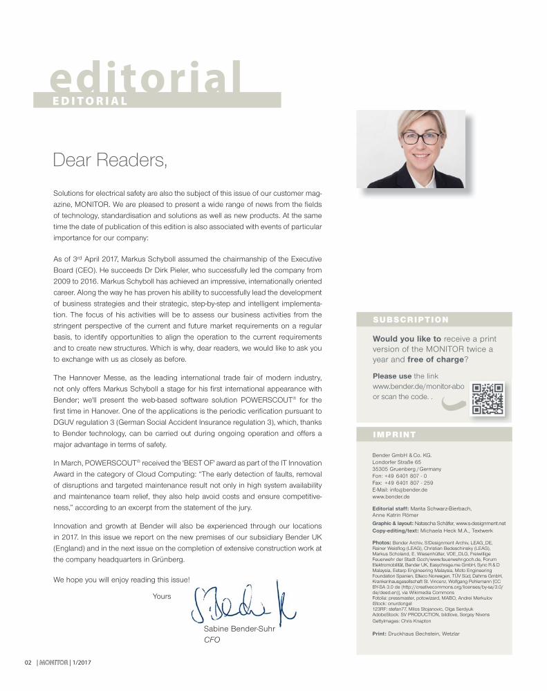
Mobile generators are indispensable aids when power needs to be supplied to equipment that has no direct access to a permanent installation ....
Following the publication of the new version of IEC 60204:2016-10 last October at international level, it can be expected that the fi nal German version of the standard will be released soon ...
Since October 2016, LEAG has been the new name for energy from the Lausitz area and Central Germany after Vattenfall sold its lignite division to the Czech companies EPH and PPF Investments ...
Energyfrom Lausitz
Electrical safety für mobile generators
New trend for machines: Signalling instead of switching
04 Electrical safety for mobile generators
11 INNOVATIONSPREIS-IT 2017 (IT INNOVATION PRIZE): BEST OF award for Bender12 Insulation monitoring for IT systems: Making electricity networks safer and more cost-effective 14 New trend for machines: Signalling instead of switching 16 The new standard DIN VDE 0100-712:2016-10 for photovoltaic: Ready for the new standard?18 The Forum ElektroMobilität e. V. presents itself: as partner platform and driver of innovation
I N N O VAT I V E P R O D U C T S
20 isoGEN523: Insulation monitoring for mobile generators
22 LINETRAXX® VMD461 and CD440: Voltage and frequency monitoring for higher nominal system voltages
24 POWERSCOUT®: Find out today what won't happen tomorrow
T E C H N I C A L A P P L I C AT I O N
27 The new Royal Liverpool Hospital: Critical role for Bender 28 Easy charging from above: EASYCHARGE.me makes electricity accessible almost everywhere
30 Sync R&D: Malaysia’s First Electric Bus32 Fourth 'MotoStudent' race at MotorLand Aragón in Spain
B E N D E R I N H O U S E
35 Electrical installations at airports: Safety in the design and operation
38 Bender branch in UK moves into new building
40 Successful symposium dedicated to hospital engineering in Bremerhaven
A G E N T S C O R N E R
42 Elteco: 40 years of cooperation and friendshipKUNDENPORTRAIT
C U S T O M E R P O R T R A I T
46 LEAG: Energy from Lausitz
49 EXHIBITIONS 2017
50 INTERVIEW with Ralf Muswieck, Market Segment Manager Manufacturing | Sales Europe & MEA of Bender
52 PRACTICAL EXPERTISE: What you should know about measuring current transformers5
Page 14 Page 46Page 04
04
F E AT U R E
for mobile generators
Electrical safety
| MONITORMONITOR | 1/2017
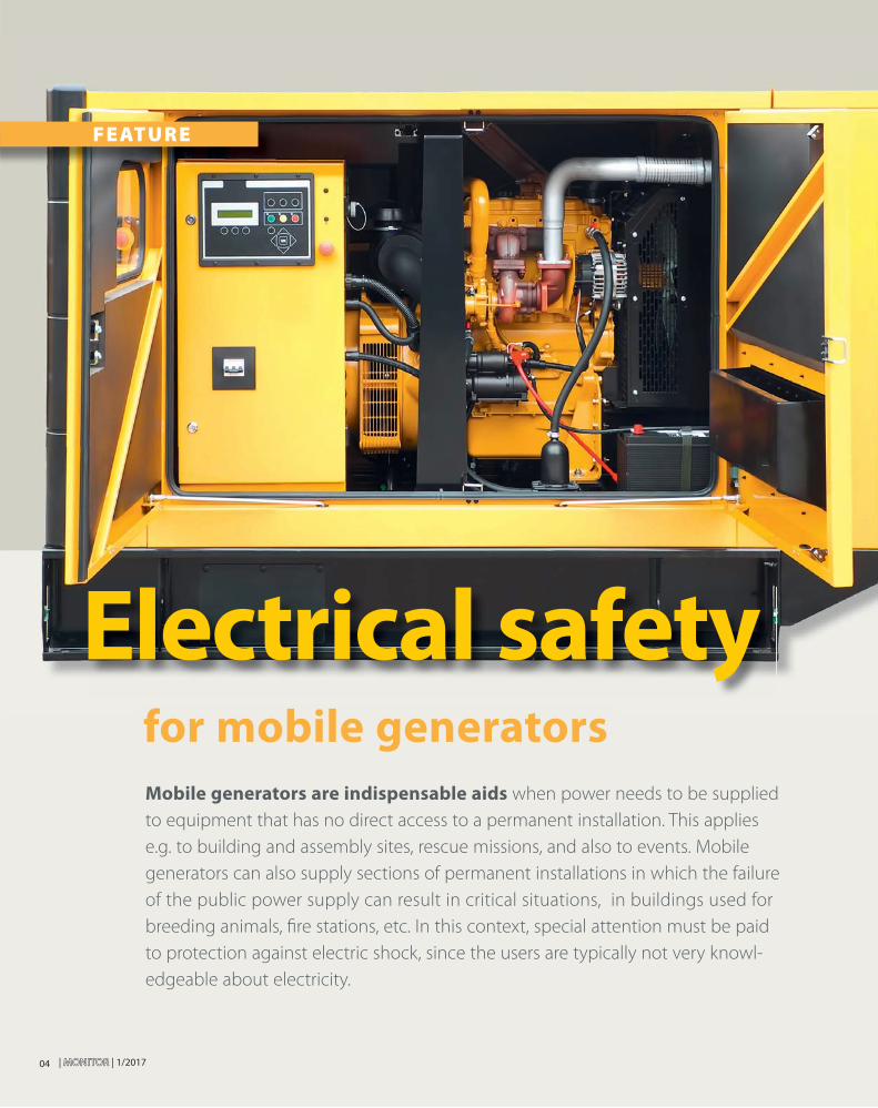
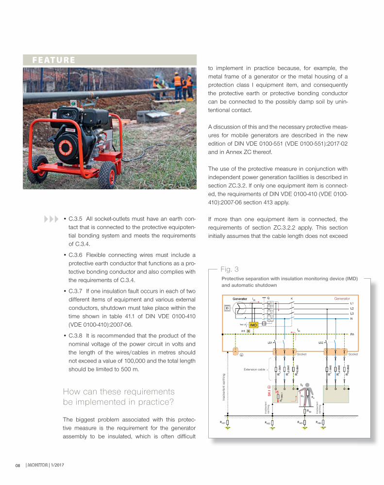
Mobile generators are indispensable aids when power needs to be supplied
to equipment that has no direct access to a permanent installation. This applies
e.g. to building and assembly sites, rescue missions, and also to events. Mobile
generators can also supply sections of permanent installations in which the failure
of the public power supply can result in critical situations, in buildings used for
breeding animals, fi re stations, etc. In this context, special attention must be paid
to protection against electric shock, since the users are typically not very knowl-
edgeable about electricity.
1/2017 | MONITORMONITOR | 05
Unclear specifi cations?
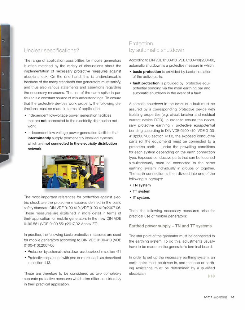
The range of application possibilities for mobile generators is often matched by the variety of discussions about the implementation of necessary protective measures against electric shock. On the one hand, this is understandable because of the many standards that generators must satisfy, and thus also various statements and assertions regarding the necessary measures. The use of the earth spike in par-ticular is a constant source of misunderstandings. To ensure that the protective devices work properly, the following dis-tinctions must be made in terms of application:
• Independent low-voltage power generation facilities that are not connected to the electricity distribution net-work.
• Independent low-voltage power generation facilities that intermittently supply permanently installed systems which are not connected to the electricity distribution network.
The most important references for protection against elec-tric shock are the protective measures defi ned in the basic safety standard DIN VDE 0100-410 (VDE 0100-410):2007-06. These measures are explained in more detail in terms of their application for mobile generators in the new DIN VDE 0100-551 (VDE 0100-551):2017-02 Annex ZC.
In practice, the following basic protective measures are used for mobile generators according to DIN VDE 0100-410 (VDE 0100-410):2007-06:
• Protection by automatic shutdown as described in section 411
• Protective separation with one or more loads as described in section 413.
These are therefore to be considered as two completely separate protective measures which also differ considerably in their practical application.
Protection by automatic shutdown
According to DIN VDE 0100-410 (VDE 0100-410):2007-06,automatic shutdown is a protective measure in which
• basic protection is provided by basic insulation of the active parts;
• fault protection is provided by protective equi-potential bonding via the main earthing bar and automatic shutdown in the event of a fault.
Automatic shutdown in the event of a fault must be assured by a corresponding protective device with isolating properties (e.g. circuit breaker and residual current device RCD). In order to ensure the neces-sary protective earthing / protective equipotential bonding according to DIN VDE 0100-410 (VDE 0100-410):2007-06 section 411.3, the exposed conductive parts (of the equipment) must be connected to a protective earth – under the prevailing conditions for each system depending on the earth connection type. Exposed conductive parts that can be touched simultaneously must be connected to the same earthing system individually in groups or together. The earth connection is then divided into one of the following subgroups:
• TN system
• TT system
• IT system.
Then, the following necessary measures arise for practical use of mobile generators:
Earthed power supply – TN and TT systems
The star point of the generator must be connected to the earthing system. To do this, adjustments usually have to be made on the generator's terminal board.
In order to set up the necessary earthing system, an earth spike must be driven in, and the loop or earth-ing resistance must be determined by a qualifi ed electrician.
| MONITORMONITOR | 1/2017
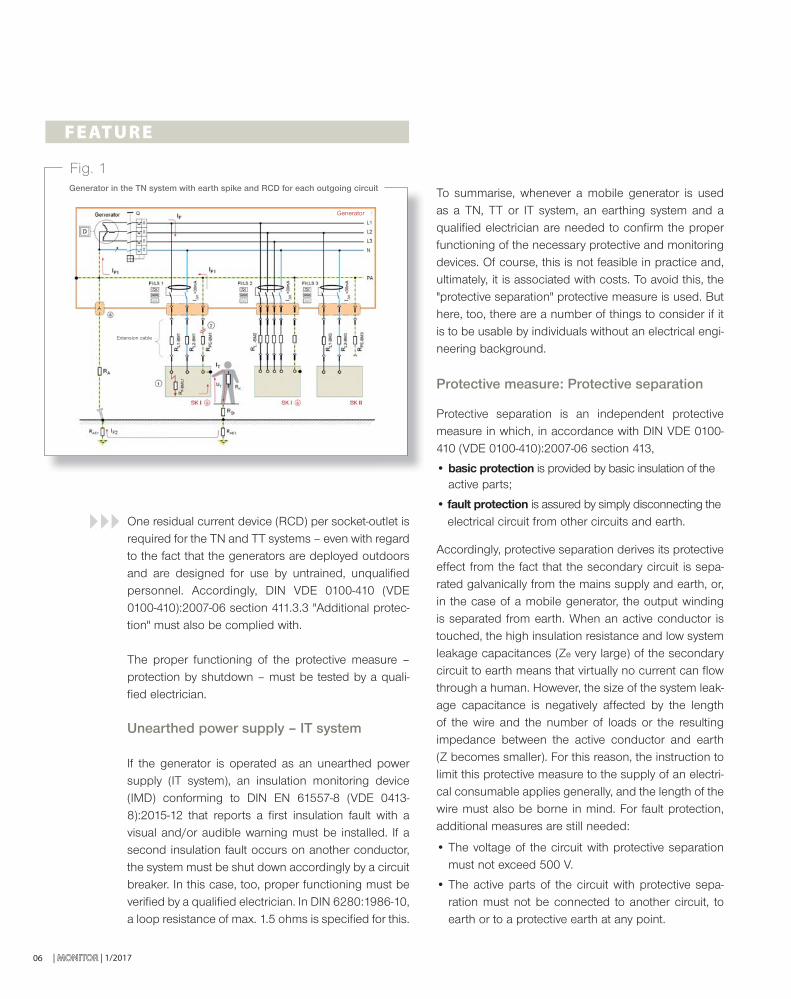
One residual current device (RCD) per socket-outlet is required for the TN and TT systems – even with regard to the fact that the generators are deployed outdoors and are designed for use by untrained, unqualifi ed personnel. Accordingly, DIN VDE 0100-410 (VDE 0100-410):2007-06 section 411.3.3 "Additional protec-tion" must also be complied with.
The proper functioning of the protective measure – protection by shutdown – must be tested by a quali-fi ed electrician.
Unearthed power supply – IT system
If the generator is operated as an unearthed power supply (IT system), an insulation monitoring device (IMD) conforming to DIN EN 61557-8 (VDE 0413-8):2015-12 that reports a fi rst insulation fault with a visual and/or audible warning must be installed. If a second insulation fault occurs on another conductor, the system must be shut down accordingly by a circuit breaker. In this case, too, proper functioning must be verifi ed by a qualifi ed electrician. In DIN 6280:1986-10, a loop resistance of max. 1.5 ohms is specifi ed for this.
06
F E AT U R E
To summarise, whenever a mobile generator is used as a TN, TT or IT system, an earthing system and a qualifi ed electrician are needed to confi rm the proper functioning of the necessary protective and monitoring devices. Of course, this is not feasible in practice and, ultimately, it is associated with costs. To avoid this, the "protective separation" protective measure is used. But here, too, there are a number of things to consider if it is to be usable by individuals without an electrical engi-neering background.
Protective measure: Protective separation
Protective separation is an independent protective measure in which, in accordance with DIN VDE 0100-410 (VDE 0100-410):2007-06 section 413,
• basic protection is provided by basic insulation of the active parts;
• fault protection is assured by simply disconnecting the electrical circuit from other circuits and earth.
Accordingly, protective separation derives its protective effect from the fact that the secondary circuit is sepa-rated galvanically from the mains supply and earth, or, in the case of a mobile generator, the output winding is separated from earth. When an active conductor is touched, the high insulation resistance and low system leakage capacitances (Ze very large) of the secondary circuit to earth means that virtually no current can fl ow through a human. However, the size of the system leak-age capacitance is negatively affected by the length of the wire and the number of loads or the resulting impedance between the active conductor and earth (Z becomes smaller). For this reason, the instruction to limit this protective measure to the supply of an electri-cal consumable applies generally, and the length of the wire must also be borne in mind. For fault protection, additional measures are still needed:
• The voltage of the circuit with protective separation must not exceed 500 V.
• The active parts of the circuit with protective sepa-ration must not be connected to another circuit, to earth or to a protective earth at any point.
Fig. 1Generator in the TN system with earth spike and RCD for each outgoing circuit
Extension cable
Generator
1/2017 | MONITORMONITOR |
• C.3.2 In the case of protective separation with more than one consumable, the requirements of section 413 (not including 413.1.2) and the subse-quent additional requirements must be met.
• C.3.3 Take precautionary steps to protect separate circuits from damage and insulation faults.
• C.3.4 Connect the exposed conductive parts together by insulated, unearthed protective con-ductors. These conductors must not be connected to the protective conductors or other exposed con-ductive parts in other circuits or to any extraneous conductive parts.
07
• The exposed conductive parts of the circuit with protective separation must not be connected to the protective earth, to the exposed conductive parts of other circuits or to earth.
• Flexible cables and wires must be clearly visible along their entire length in places that are exposed to mechanical loads.
Provided they comply strictly with these requirements, protective separation with a load may also be used by individuals without an electrical engineering back-ground. In practice, however, mobile generators are usually equipped with more than one socket-outlet. Therefore, the requirements of Annex C.3 of DIN VDE 0100-410 (VDE 0100-410):2007-06 apply as well.
Annex C.3 of this standard describes the protective measures with more than one consumable, which may only be operated and monitored by qualifi ed electricians or individuals who have received electrical training.
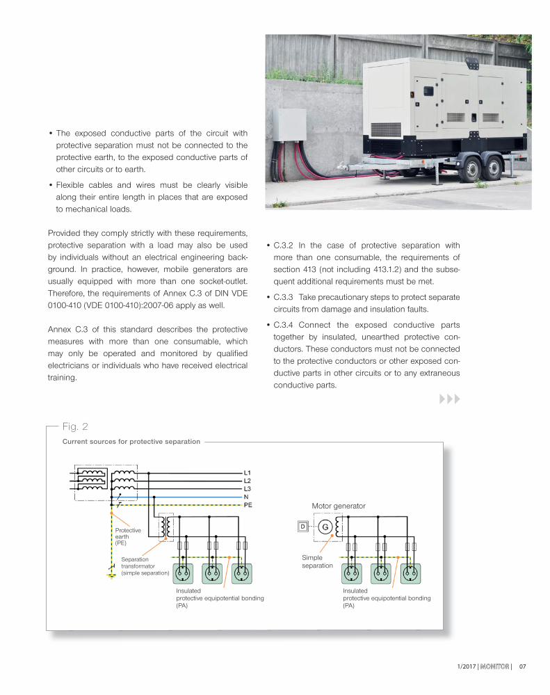
Fig. 2Current sources for protective separation
Motor generator
Insulated protective equipotential bonding (PA)
Insulated protective equipotential bonding (PA)
Simple separation
Separation transformator(simple separation)
Protective earth (PE)
| MONITORMONITOR | 1/201708
• C.3.5 All socket-outlets must have an earth con-tact that is connected to the protective equipoten-tial bonding system and meets the requirements of C.3.4.
• C.3.6 Flexible connecting wires must include a protective earth conductor that functions as a pro-tective bonding conductor and also complies with the requirements of C.3.4.
• C.3.7 If one insulation fault occurs in each of two different items of equipment and various external conductors, shutdown must take place within the time shown in table 41.1 of DIN VDE 0100-410 (VDE 0100-410):2007-06.
• C.3.8 It is recommended that the product of the nominal voltage of the power circuit in volts and the length of the wires/cables in metres should not exceed a value of 100,000 and the total length should be limited to 500 m.
How can these requirements be implemented in practice?
The biggest problem associated with this protec-tive measure is the requirement for the generator assembly to be insulated, which is often diffi cult
F E AT U R Eto implement in practice because, for example, the metal frame of a generator or the metal housing of a protection class I equipment item, and consequently the protective earth or protective bonding conductor can be connected to the possibly damp soil by unin-tentional contact.
A discussion of this and the necessary protective meas-ures for mobile generators are described in the new edition of DIN VDE 0100-551 (VDE 0100-551):2017-02 and in Annex ZC thereof.
The use of the protective measure in conjunction with independent power generation facilities is described in section ZC.3.2. If only one equipment item is connect-ed, the requirements of DIN VDE 0100-410 (VDE 0100-410):2007-06 section 413 apply.
If more than one equipment item is connected, the requirements of section ZC.3.2.2 apply. This section initially assumes that the cable length does not exceed
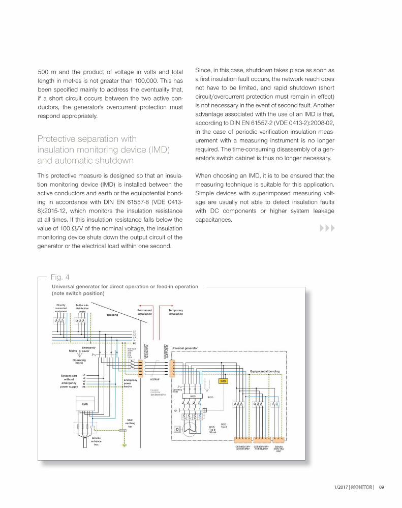
Fig. 3Protective separation with insulation monitoring device (IMD) and automatic shutdown
Extension cable
Socket Socket
Inad
vert
ent e
arth
ing
Inad
vert
ent
eart
hing
Inad
vert
ent
eart
hing
Generator
1/2017 | MONITORMONITOR | 09
500 m and the product of voltage in volts and total length in metres is not greater than 100,000. This has been specifi ed mainly to address the eventuality that, if a short circuit occurs between the two active con-ductors, the generator's overcurrent protection must respond appropriately.
Protective separation with insulation monitoring device (IMD) and automatic shutdown
This protective measure is designed so that an insula-tion monitoring device (IMD) is installed between the active conductors and earth or the equipotential bond-ing in accordance with DIN EN 61557-8 (VDE 0413-8):2015-12, which monitors the insulation resistance at all times. If this insulation resistance falls below the value of 100 Ω/V of the nominal voltage, the insulation monitoring device shuts down the output circuit of the generator or the electrical load within one second.
Since, in this case, shutdown takes place as soon as a fi rst insulation fault occurs, the network reach does not have to be limited, and rapid shutdown (short circuit/overcurrent protection must remain in effect) is not necessary in the event of second fault. Another advantage associated with the use of an IMD is that, according to DIN EN 61557-2 (VDE 0413-2):2008-02, in the case of periodic verifi cation insulation meas-urement with a measuring instrument is no longer required. The time-consuming disassembly of a gen-erator's switch cabinet is thus no longer necessary.
When choosing an IMD, it is to be ensured that the measuring technique is suitable for this application. Simple devices with superimposed measuring volt-age are usually not able to detect insulation faults with DC components or higher system leakage capacitances.
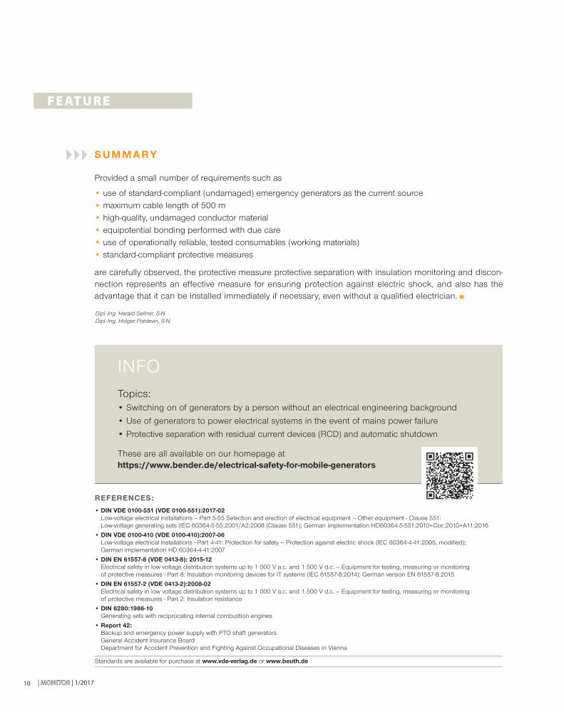
Fig. 4Universal generator for direct operation or feed-in operation (note switch position)
Directly connected equipment
Building
Permanent installation
Temporary installation
Universal generator
Equipotential bonding
Operating mode
Emergency power feed-in
Main earthing
bar
Insulation monitoring
Isla
nd o
pera
tion
Em
erge
ncy
pow
er
Service entrance
box
System part without
emergency power supply
Mains
Operating mode
Emergency power
To the sub-distribution
board
| MONITORMONITOR | 1/201710
F E AT U R E
INFOTopics:• Switching on of generators by a person without an electrical engineering background
• Use of generators to power electrical systems in the event of mains power failure
• Protective separation with residual current devices (RCD) and automatic shutdown These are all available on our homepage at https://www.bender.de/electrical-safety-for-mobile-generators
REFERENCES:
• DIN VDE 0100-551 (VDE 0100-551):2017-02Low-voltage electrical installations – Part 5-55 Selection and erection of electrical equipment – Other equipment - Clause 551: Low-voltage generating sets (IEC 60364-5-55:2001/A2:2008 (Clause 551); German implementation HD60364-5-551:2010+Cor.:2010+A11:2016
• DIN VDE 0100-410 (VDE 0100-410):2007-06Low-voltage electrical installations - Part 4-41: Protection for safety – Protection against electric shock (IEC 60364-4-41:2005, modifi ed); German implementation HD 60364-4-41:2007
• DIN EN 61557-8 (VDE 0413-8): 2015-12Electrical safety in low voltage distribution systems up to 1 000 V a.c. and 1 500 V d.c. – Equipment for testing, measuring or monitoring of protective measures - Part 8: Insulation monitoring devices for IT systems (IEC 61557-8:2014); German version EN 61557-8:2015
• DIN EN 61557-2 (VDE 0413-2):2008-02Electrical safety in low voltage distribution systems up to 1 000 V a.c. and 1 500 V d.c. – Equipment for testing, measuring or monitoring of protective measures - Part 2: Insulation resistance
• DIN 6280:1986-10Generating sets with reciprocating internal combustion engines
• Report 42: Backup and emergency power supply with PTO shaft generatorsGeneral Accident Insurance BoardDepartment for Accident Prevention and Fighting Against Occupational Diseases in Vienna
Standards are available for purchase at www.vde-verlag.de or www.beuth.de
Dipl.-Ing. Harald Sellner, S-NDipl.-Ing. Holger Potdevin, S-N
S U M M A RY
Provided a small number of requirements such as
• use of standard-compliant (undamaged) emergency generators as the current source• maximum cable length of 500 m• high-quality, undamaged conductor material• equipotential bonding performed with due care• use of operationally reliable, tested consumables (working materials)• standard-compliant protective measures
are carefully observed, the protective measure protective separation with insulation monitoring and discon-nection represents an effective measure for ensuring protection against electric shock, and also has the advantage that it can be installed immediately if necessary, even without a qualifi ed electrician.
N E W S W O R T HY
1/2017 | MONITOR | 111/2017 | MONMON
INFOFor more information see: www.imittelstand.de/innovationspreis-it/2017.
INNOVATIONSPREIS-IT 2017 (IT INNOVATION PRIZE) BEST OF award for Bender
In 2017, several thousand companies – more than ever before – entered the competition under the motto “MISSION. INNOVATION” with smart IT solutions that give an idea of the innovative power of the German SME community.
An independent and just under 100-strong jury made up of professors, scientists, trade journalists and IT experts assessed the innovative content of the solu-tions and their suitability for small and medium-sized businesses.
POWERSCOUT®, currently the only software of its kind on the market, offers SMEs a simple, effective and affordable tool for reliably monitoring electrical instal-lations. Recognising errors at an early stage, rectifying faults and targeted maintenance ensure a high level of system availability, take the strain off maintenance teams, save money and guarantee competitiveness.
In addition to the 38 category winners, this year one win-ner was also selected per federal state and two special awards were allocated for Austria and Switzerland. The prize-giving ceremony was held within the framework of the CeBIT, as offi cial partner, from 20 to 24 March 2017. The winners and fi nalists will also be announced via the media network of Initiative Mittelstand.
With the IT INNOVATION PRIZE, Initiative Mittelstand (SME Initiative) has been
recognising companies who provide innovative IT solutions and a high benefi cial value
for SMEs since 2005. This year Bender won the BEST OF award in the “Cloud Computing”
category with the web-based software POWERSCOUT®.
Andrea Gossel, S-COM
| MONITORMONITOR | 1/2017
N E W S W O R T HY
12
Making electricity networks safer and more cost-eff ective
Insulation monitoring for IT systems
In an IT system, no active conductor is directly connect-ed to earth. All of the active components are insulated against earth or connected to earth via a suffi ciently large impedance. In the event of a fault in the insula-tion, this means that no large earth fault current will fl ow – instead, just a comparatively small leakage current or residual current will fl ow. The system can continue to run without interruption. This maximises operational reliability in sensitive areas such as hospital operating theatres, power plants or industrial produc-tion systems. In these areas in particular, IT systems deliver failure-free power supplies, protect people’s health and prevent expensive plant downtimes.
Conventional power systems are implemented via earthed TN or TT systems, which are also used in residential buildings. In the event of a fault, current fl ows through the protective earth conductor and trips the upstream fuse or the upstream fault-current circuit breaker. Although this means that the danger is averted, it also means that the fl ow of electricity is interrupted.
IT systems: no earthing – full safety
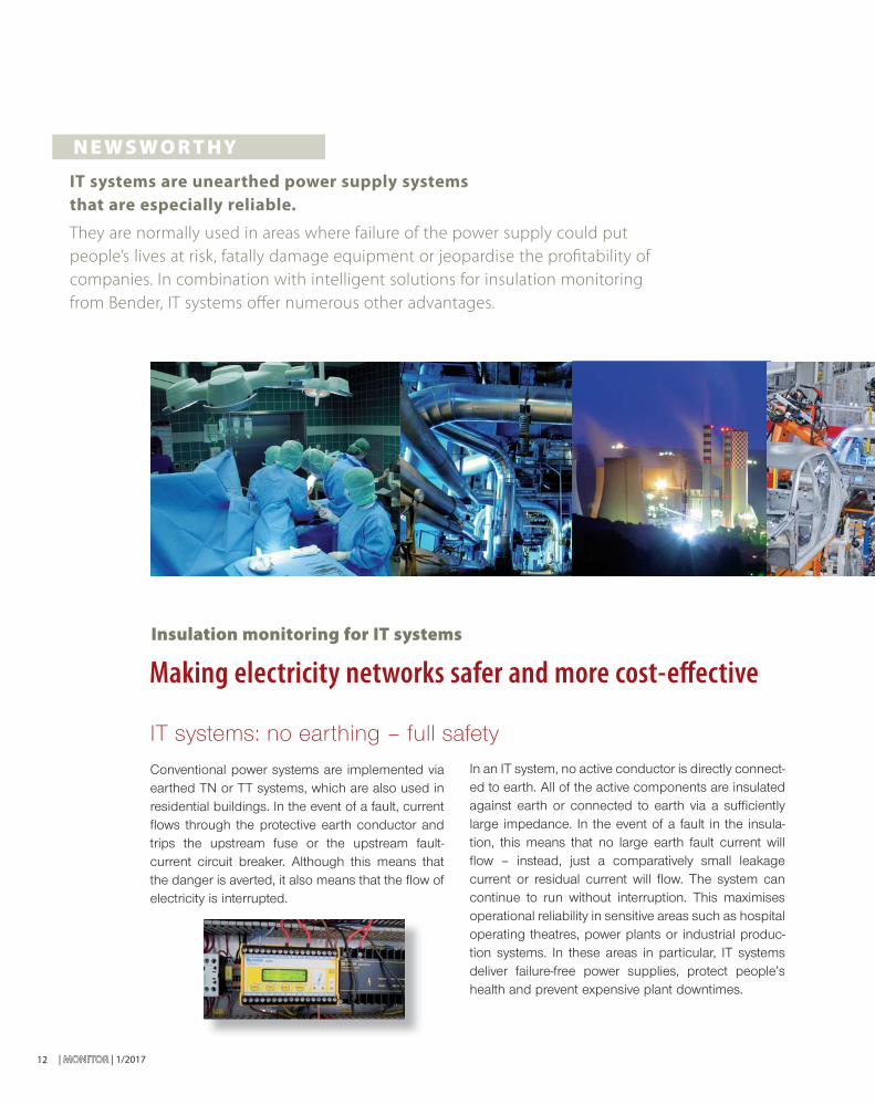
IT systems are unearthed power supply systems
that are especially reliable.
They are normally used in areas where failure of the power supply could put
people’s lives at risk, fatally damage equipment or jeopardise the profi tability of
companies. In combination with intelligent solutions for insulation monitoring
from Bender, IT systems off er numerous other advantages.
1/2017 | MONITORMONITOR | 13
Insulation monitoring in IT systems
In order for potential faults to be detected in IT systems as early as possible, additional protective measures are required. DIN VDE 0100-410 (VDE 0100-410):2007-06 states that IT systems are only permitted to be operated in conjunction with an insulation monitoring device. Such a device monitors the system for any deterioration in insu-lation and allows preventive action to be taken if a fault is imminent.
With the ISOMETER® series, Bender offers a range of devices that comply with all of the relevant standards and offer innovative and intelligent solutions for insulation mon-itoring. The ISOSCAN® devices for insulation fault location, which are also compliant with all relevant standards.
Ideal areas of application for IT systems
IT systems with insulation monitoring devices can be used for a very wide range of applications and are always the right solution in cases where an uninterrupted power supply is required. This could be the case, for example, in areas where power failure could put people’s lives at immediate risk – such as in hospitals, mines, control rooms, railways or airports. On the other hand, IT systems can also be used in production plants where even short power failures would result in long and therefore expen-sive production downtimes. On top of this, IT systems are also suitable for critical applications like control circuits and mobile power generators, as well as for electric vehi-cles, photovoltaic systems and industrial systems with controlled drives.
Increasing safety whilst lowering costs
IT systems with insulation monitoring reliably prevent op-erational interruptions. Even in the event of a fi rst insula-tion fault and earth fault, systems can continue to run. As a result, IT systems not only increase safety for people who depend on these systems, but they also improve opera-tional reliability and therefore reduce operating costs.
In addition, IT systems lower the costs for main-tenance and servicing. Thanks to the insulation monitoring devices, any deterioration in the level of insulation can be detected at an early stage. If an insulation fault is present, it can be located while the system is still running, without any downtime. Since no RCD tests or RISO measurements are required on continuously monitored IT systems, which are constantly maintained by qualifi ed electricians, the costs for periodic inspections are reduced.
Insulation faults are the most common causes of fi res in electricity networks. This means that IT sys-tems with insulation monitoring also make a major contribution to improved fi re safety. If insulation faults are detected and located early on, this mini-mises the likelihood of a fi re. Safer power systems with Bender solutions
Bender is a long-standing specialist in the safe han-dling of electrical power. The company’s innovative and extremely reliable products protect people, machinery and plants. Bender assists its customers with the planning and realisation of new electricity networks and helps them to modernise and opti-mise existing networks.
Thanks to its wide-ranging expertise and know-how, Bender therefore offers the perfect basis for reliable and customer-specifi c solutions. Among others, the company has supplied systems for the deep sea diving unit of the European GEOSTAR research project and for the spaceport in Alcantara/Brazil. In addition, its products are also found in numerous industrial plants, vehicles, hospitals and power plants all around the world.
Marco Michels, txtconcept
„Bender assists its customers with the planning and realisation of new
electricity networks and helps them to modernise
and optimise existing networks.”
| MONITORMONITOR | 1/2017
Signalling instead of switching
New trend for machines:
Following the publication of the new version of IEC 60204:2016-10 last October at international level, it can be expected that the fi nal German version
of the standard “Safety of machinery – Part 1: General requirements”, which was
published as a draft version back in October 2014, will be released soon. In terms
of power supplies for machines, a clear new trend has emerged: Signalling instead
of switching.
N E W S W O R T HY
14
1/2017 | MONITORMONITOR |
can assist maintenance since it locates insulation faults whilst operations are ongoing, without the need to shut down the machinery.
Furthermore, in section 6.3.3 for TN and TT systems the standard recommends the use of an insulation monitoring device (RCM) as per IEC 62020 in order to improve pre-ventative maintenance.
Bender offers a wide range of products to ensure elec-trical safety of machinery. This not only comprises the ISOMETER® insulation monitoring devices, insulation fault location systems (IFLS) and residual current monitors (RCM), but also devices for other tasks such as voltage and current monitoring are also available.
Regardless of whether the reference is to a main or a control circuit: Provided that no risk is present, an initial insulation fault should not trip a protective device and thus lead to an immediate interruption of the circuit. Particularly in complex, interrelated processes, a shutdown can have fatal consequences, shut down the entire production and also damage machinery. In some cases not only the machinery has to be repaired, but high restart costs can also be incurred. This is where the machinery planner or designer comes in. By selecting the right system type, potential hazards can be prevented and, as a result, maintenance can be rendered more predictable and cost-effective.
The basic safety standard DIN VDE 0100-410 (VDE 0100-410) is of relevance for protection against electric shock. It defi nes the well-known system types TN, TT and IT, together with the necessary protection and monitoring devices. The IT system is the only network where a shutdown is not necessary after an initial insulation fault. This also applies to electrical machinery, since standard IEC 60204-1: 2016-10 refers to the requirements of IEC 60364-4-41: 2005 or the German version DIN VDE 0100-410 (100-410) in the relevant sections.
A fundamental change here is the fact that in the “old” version of DIN EN 60204-1 (VDE 0113-1):2007-06 for con-trol circuits in accordance with section 9.4.3, it was only necessary to fi t the unearthed control circuit (IT system) with a device which automatically interrupts the circuit in the event of an earth fault. In principle, this continues to apply. However, section 9.4.3.1, 2) now states that it can be suffi cient to use an insulation monitoring device (e.g. in compliance with IEC 61557-8), which issues an acoustic or visual signal to the machine should a shutdown present a risk to operation of the machine/system or if continued operation is required even in the case of an earth fault.
Alongside this amendment, the requirements for unearthed main circuits (IT systems) were also defi ned more precisely. Section 6.3.3 demands that the relevant requirements of IEC 60364-4-41 are taken into account. As such, in accordance with IEC 61557-8 or DIN EN 61557-8 (VDE 0413-8):2007-06 for IT systems, an insula-tion monitoring device which reports the fi rst insulation fault is required. In the subsequent explanatory note, it is pointed out that with larger machinery an insulation fault location system (IFLS) acc. DIN EN 61557-9 (VDE 0413-9)
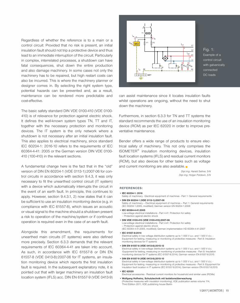
Fig. 1: Example of a
control circuit
with galvanically
connected
DC loads
REFERENCES:
• IEC 60204-1: 2016Safety of machinery - Electrical equipment of machines - Part 1: General requirements
• DIN EN 60204-1 (VDE 0113-1):2007-06Safety of machinery – Electrical equipment of machines – Part 1: General requirements (IEC 60204-1:2005, modifi ed); German version EN 60204-1:2006
• IEC 60364-4-41:2005Low-voltage electrical installations - Part 4-41: Protection for safety – Protection against electric shock
• DIN VDE 0100-410 (VDE 0100-410):2007-06Low-voltage electrical installations - Part 4-41: Protection for safety – Protection against electric shock (IEC 60364-4-41:2005, modifi ed); German implementation HD 60364-4-41:2007
• IEC 61557-8:2014 Electrical safety in low voltage distribution systems up to 1 000 V a.c. and 1 500 V d.c. - Equipment for testing, measuring or monitoring of protective measures - Part 8: Insulation monitoring devices for IT systems
• DIN EN 61557-8 (VDE 0413-8):2015-12Electrical safety in low-voltage distribution systems up to 1 000 V a.c. and 1 500 V d.c. -Equipment for testing, measuring or monitoring of protective measures - Part 8: Insulation monitoring devices for IT systems (IEC 61557-8:2014); German version EN 61557-8:2015
• DIN EN 61557-9 (VDE 0413-9):2015-10Electrical safety in low-voltage distribution systems up to 1 000 V a.c. and 1 500 V d.c. - Equipment for testing, measuring or monitoring of protective measures - Part 9: Equipment for insulation fault location in IT systems (IEC 61557-9:2014); German version EN 61557-9:2015
• IEC 62020Electrical accessories - Residual current monitors for household and similar uses (RCMs)
• Wolfgang Hofheinz, Schutztechnik mit Isolationsüberwachung(Protective measures with insulation monitoring), VDE publication series volume 114, Third Edition 2011, VDE publishing house Berlin
15
Dipl.-Ing. Harald Sellner, S-N
Dipl.-Ing. Holger Potdevin, S-N
16 | MONITORMONITOR | 1/2017
Ready for the new standard?
Practice has repeatedly shown that damage can go unno-ticed for weeks or even months. The weaknesses and risks of PV systems can, for example, comprise:
• UV-induced brittleness (material fatigue) [1]
• Electrical shock [2]
• Fire safety and electric arc risk [3]
• Ammonia resistance, environmental conditions, cable routing [4]
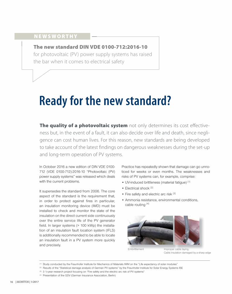
Embrittlement Improper cable laying: Cable insulation damaged by a sharp edge
In October 2016 a new edition of DIN VDE 0100-712 (VDE 0100-712):2016-10 “Photovoltaic (PV) power supply systems” was released which deals with the current problems.
It supersedes the standard from 2006. The core aspect of the standard is the requirement that, in order to protect against fi res in particular, an insulation monitoring device (IMD) must be installed to check and monitor the state of the insulation on the direct current side continuously over the entire service life of the PV generator fi eld. In larger systems (> 100 kWp) the installa-tion of an insulation fault location system (IFLS) is additionally recommended to be able to locate an insulation fault in a PV system more quickly and precisely.
The quality of a photovoltaic system not only determines its cost eff ective-
ness but, in the event of a fault, it can also decide over life and death, since negli-
gence can cost human lives. For this reason, new standards are being developed
to take account of the latest fi ndings on dangerous weaknesses during the set-up
and long-term operation of PV systems.
N E W S W O R T HY
The new standard DIN VDE 0100-712:2016-10 for photovoltaic (PV) power supply systems has raised
the bar when it comes to electrical safety
[1] Study conducted by the Fraunhofer Institute for Mechanics of Materials IWM on the “Life expectancy of solar modules”[2] Results of the “Statistical damage analysis of German PV systems” by the Fraunhofer Institute for Solar Energy Systems ISE[3] 3 ½-year research project focusing on “Fire safety and the electric arc risk of PV systems”[4] Presentation of the GDV (German Insurance Association, Berlin)
Embmbritrittletlemenmentt ImpImproproperer cabcablele laylayinging::
1/2017 | MONITORMONITOR | 17
This frequently leads to discussions as to how much the PV system insurer will pay to cover such failures. It is thus in the interest of the operator to detect and, more impor-tantly, to locate an insulation fault at an early stage by means of suitable system monitoring.
The insulation monitoring devices (IMDs) themselves must comply with DIN EN 61557-8:2015-12 Appendices C and D. This ensures that the special requirements for IMD measurement technology in the PV sector are taken in consideration. To this end, the standard distinguishes between
• Insulation monitoring devices for photovoltaic power supply systems (PV-IMD)
• Insulation monitoring function for photovoltaic inverters (PV-IMF) or for charge controllers.
Another new aspect is the requirement that these devic-es are marked with the respective"PV-IMD" or "PV-IMF" pictograms. Thereby, the user can easily recognise if the correct device is being used in the system.
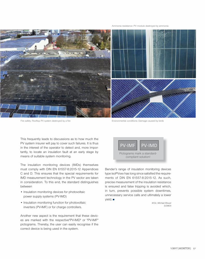
Fire safety: Rooftop PV system destroyed by a fi re Environmental conditions: Damage caused by birds
Ammonia resistance: PV module destroyed by ammonia
Bender’s range of insulation monitoring devicestype isoPVxxx has long since satisfi ed the require-ments of DIN EN 61557-8:2015-12. As such, precise measurement of the insulation resistance is ensured and false tripping is avoided which, in turn, prevents possible system downtimes, unnecessary service calls and ultimately a lower yield.
M.Sc. Michael BreuerS-EMEA
Pictograms mark a standard-compliant solution!
| MONITORMONITOR | 1/201718
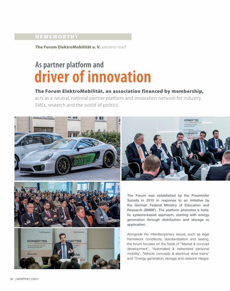
The Forum was established by the Fraunhofer Society in 2010 in response to an initiative by the German Federal Ministry of Education and Research (BMBF). The platform promotes a holis-tic systems-based approach, starting with energy generation through distribution and storage to application.
Alongside the interdisciplinary issues, such as legal framework conditions, standardisation and testing, the forum focuses on the fi elds of “Market & concept development”, “Automated & networked personal mobility”, "Vehicle concepts & electrical drive trains” and “Energy generation, storage and network integra-
As partner platform and
driver of innovation
The Forum ElektroMobilität e. V. presents itself
The Forum ElektroMobilität, an association financed by membership, acts as a neutral, national partner platform and innovation network for industry,
SMEs, research and the world of politics.
N E W S W O R T HY

1/2017 | MONITORMONITOR | 19
tion”. The technical advisory board, whose membership is drawn from the fi elds of research and industry, ensures consistency between research and practical application, acting as an advisory body in the practical realisation and structuring of the focus areas.
The head offi ce acts as a central clearing house and cre-ates signifi cant added value with services in the defi ned areas of activity. The active involvement of members and the regular dialogue generate impulses and ideas that contribute directly to the work of the forum.
The mission of the association is to establish and nurture a strong community drawn from the fi elds of industry, science and politics, which can proactively assess trends and strengthen the position of its members by generating new knowledge and contacts. The forum aims to raise the profi le of electromobility, increasing public awareness of the industry. By contributing from their own respective areas of expertise, members will be able to initiate new joint projects, which will result in new ideas and business relationships as well as services and products.
The pooling of strengths and their presentation is designed to encourage cooperation across industry and system boundaries. Furthermore, the integration of electromobility as a fundamental component in existing and new solutions and concepts is to be driven forward and alternative drive technologies and concepts identifi ed for early market introduction, all with a view to creating a leading market for electromobility in Germany.
The Forum sends out a monthly newsletter, publishes contributions twice a year in the quality magazine “E-MAIL” and maintains an online presence at www.forum-elektromobili-taet.de. In addition to networking and selec-tive mediation of contacts, annual events are organised on specifi c subjects that are
relevant to electromobility. A highlight in the indus-try’s calendar is the annual KONGRESS, this year to be held on 1 and 2 June 2017 in Berlin, which offers a showcase for cutting-edge projects and developments. At the event, now in its 8th year, 250 visitors from the sector will hear talks by high-profi le speakers, and will have the opportunity to discuss developments and to speak directly with developers, manufacturers and service providers.
Michael KlugerForum Elektromobilität e.V.
The pubquaontaetiva
INFO
If you have any questions regarding services and offers, please contact the head offi ce of Forum ElektroMobilität e. V. by calling: 030 240474 - 58 or mailing: [email protected]
More information is also available at
www.forum-elektromobilitaet.de
Interdisciplinary issues
Market & concept development
Automated & networked personal
mobility
Energy generation, energy storage &
network integration
Vehicle concepts & electrical drive trains
Automotive industry Operators

| MONITOR | 1/201720
Insu
lati
on
mo
nit
ori
ng
de
vic
e I
SO
ME
TE
R®
iso
GE
N5
23
with isoGEN523
Insulation monitoring
for mobile generators
With a single load connected to the generator, no further protective measures are required. However, if
more than one operating resource is connect-ed to the generator, the requirements of the new section ZC.3.2.2 of DIN VDE 0100-551,
issued in February 2017, apply. The protective measure is then to be executed so that an insu-lation monitoring device (IMD) complying with
DIN EN 61557-8:2015-12 is installed between the active conductors and the equipotential bond-ing. This must continuously monitor the insulation
resistance. If the insulation resistance falls below the value of 100 Ω/V (230 V - 23 kΩ), the insulation monitor-ing device switches the output circuit of the generator or the electrical load off within one second.
Bender has been a supplier of insulation monitoring devices that are
specified for use in mobile power generators for many years. This ISOMETER®
product family is generally used for independent low-voltage power gen-
eration facilities that are not connected to the electricity distribution grid.
This application is more precisely described in the new version of DIN VDE
0100-551 (VDE 0100-551):2017-02. The protective separation with one or
more loads is described in DIN VDE 0100-410 (VDE 0100-410):2007-06.
imla
DItheing.
resistvalue of 1ing devicor the ele
Fig. 1: Insulation monitoring device ISOMETER® isoGEN523
INNOVATIVE P RO D U C TS
1/2017 | MONITORMONITOR | 21
When selecting the IMD, it is to be ensured that the measuring technology is suitable for this application. The simplest devices with superimposed DC measur-ing voltage are usually not able to detect insulation faults with DC components or higher system leak-age capacitances. The current IMDs, such as the ISOMETER® of type IR423 and IR123 from Bender, meet these requirements and are suitable for mounting on DIN rails or in the control cabinet of a generator.
The ISOMETER® isoGEN523 was developed in order to offer an IMD that complies with the current norma-tive requirements, which is also suitable for extreme environmental conditions. In principle, this is a further development of IR423.
Unlike its predecessor, the unit is housed in a sealed case and can be connected via a cable in the genera-tor. A port monitor, which is activated when the device is turned on and then hourly by an automatic self-test, detects whether the necessary ports to the generator and the equipotential bonding are still open. This fea-ture is especially important as the device can also be used for high shock and vibration requirements, as
well as in a higher temperature range. Even heavy pollution or high humidity are not a problem for the isoGEN523.
The isoGEN523 offers the possibility of system isolation as an additional feature. This means that the IMD automatically disconnects from the monitored power supply in a volt-age-free state via integrated switch contacts. The advantage for the operator is that the coupling resistance of the IMD is no longer present between the generator winding and the equipotential bonding (PE) in an insulation test of the gener-ator by means of an insulation test device. This ensures that the limit value of the test current induced by the insulation test is not exceeded by the ISOMETER®. The operator can therefore perform a real insulation test with a test voltage of up to 500 V, without dismantling the generator or the isoGEN523 having to be disconnected from the generator.
Previous devices of this type such as the ISOMETER® types IRG100RS, IRG700RS/AS or IR140RS can also be replaced with this device version.
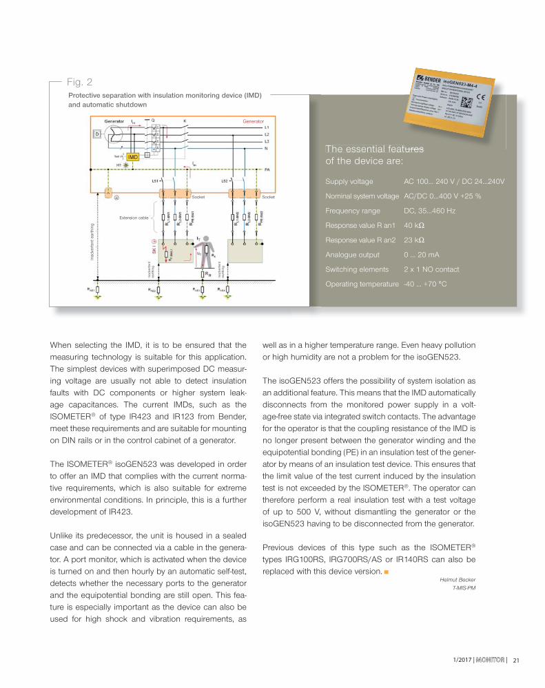
Fig. 2Protective separation with insulation monitoring device (IMD) and automatic shutdown
The essential features of the device are:
Supply voltage AC 100... 240 V / DC 24...240V
Nominal system voltage AC/DC 0...400 V +25 %
Frequency range DC, 35...460 Hz
Response value R an1 40 kΩ
Response value R an2 23 kΩ
Analogue output 0 ... 20 mA
Switching elements 2 x 1 NO contact
Operating temperature -40 ... +70 °C
ures
Helmut Becker
T-MIS-PM
Extension cable
Socket Socket
Inad
vert
ent e
arth
ing
Inad
vert
ent
eart
hing
Inad
vert
ent
eart
hing
Generator
| MONITORMONITOR | 1/2017
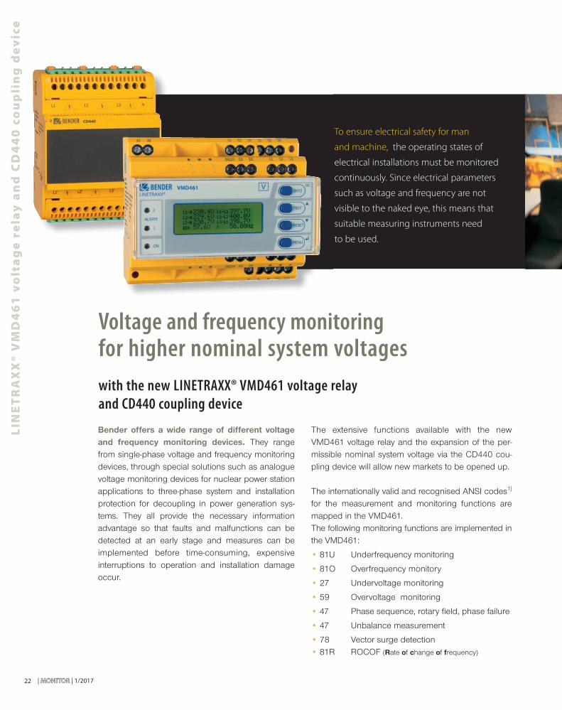
with the new LINETRAXX® VMD461 voltage relay and CD440 coupling device
Voltage and frequency monitoring for higher nominal system voltages
Bender offers a wide range of different voltage and frequency monitoring devices. They range from single-phase voltage and frequency monitoring devices, through special solutions such as analogue voltage monitoring devices for nuclear power station applications to three-phase system and installation protection for decoupling in power generation sys-tems. They all provide the necessary information advantage so that faults and malfunctions can be detected at an early stage and measures can be implemented before time-consuming, expensive interruptions to operation and installation damage occur.
The extensive functions available with the new VMD461 voltage relay and the expansion of the per-missible nominal system voltage via the CD440 cou-pling device will allow new markets to be opened up.
The internationally valid and recognised ANSI codes1] for the measurement and monitoring functions are mapped in the VMD461.The following monitoring functions are implemented in the VMD461:
• 81U Underfrequency monitoring
• 81O Overfrequency monitory
• 27 Undervoltage monitoring
• 59 Overvoltage monitoring
• 47 Phase sequence, rotary fi eld, phase failure
• 47 Unbalance measurement
• 78 Vector surge detection• 81R ROCOF (Rate of change of frequency)
To ensure electrical safety for man
and machine, the operating states of
electrical installations must be monitored
continuously. Since electrical parameters
such as voltage and frequency are not
visible to the naked eye, this means that
suitable measuring instruments need
to be used.
22
LIN
ET
RA
XX
® V
MD
46
1 v
olt
ag
e r
ela
y a
nd
CD
44
0 c
ou
pli
ng
de
vic
e
1/2017 | MONITORMONITOR |
INNOVATIVE P RO D U C TS
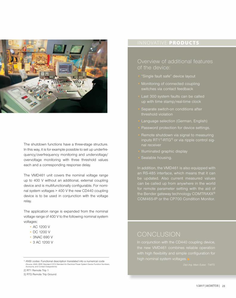
The shutdown functions have a three-stage structure. In this way, it is for example possible to set up underfre-quency/overfrequency monitoring and undervoltage/overvoltage monitoring with three threshold values each and a corresponding response delay.
The VMD461 unit covers the nominal voltage range up to 400 V without an additional, external coupling device and is multifunctionally confi gurable. For nomi-nal system voltages > 400 V the new CD440 coupling device is to be used in conjunction with the voltage relay.
The application range is expanded from the nominal voltage range of 400 V to the following nominal system voltages:
• AC 1200 V• DC 1200 V• 3NAC 690 V• 3 AC 1200 V
23
Overview of additional features of the device:
• “Single fault safe” device layout
• Monitoring of connected coupling switches via contact feedback
• Last 300 system faults can be called up with time stamp/real-time clock
• Separate switch-on conditions after threshold violation
• Language selection (German, English)
• Password protection for device settings.
• Remote shutdown via signal to measuring inputs RT12]-RTG3] or via ripple control sig-nal receiver
• Illuminated graphic display
• Sealable housing.
In addition, the VMD461 is also equipped with an RS-485 interface, which means that it can be updated. Also current measured values can be called up from anywhere in the world for remote parameter setting with the aid of the Bender gateway technology COMTRAXX® COM465-IP or the CP700 Condition Monitor.
CONCLUSIONIn conjunction with the CD440 coupling device, the new VMD461 combines reliable operation with high fl exibility and simple confi guration for high nominal system voltages.
Dipl.-Ing. Marc Euker, T-MTS
1] ANSI codes: Functional description translated into a numerical code (Source: ANSI /IEEE Standard C37.2 Standard for Electrical Power System Device Function Numbers, Acronyms, and Contact Designations)
2] RT1 Remote Trip 1
3] RTG Remote Trip Ground

| MONITORMONITOR | 1/201724
INNOVATIVE P RO D U C TS
PO
WE
RS
CO
UT
®
Monitoring and analysis of your electrical installation made easy
POWERSCOUT®
Find out today what won't happen tomorrow
For facility managers, plant managers and electrical professionals who are
responsible for power supply, being able to identify potential problems before
they occur in order to respond appropriately is ideal. Those responsible also have
to rely on the appropriate technology to increase the availability and safety of the
electrical system.
The solution is POWERSCOUT® – the next generation of web-based software
for the continuous and smooth predictive monitoring of critical power systems.
This enables proactive maintenance, therefore avoiding unplanned downtime and
protects against fi res which are caused by overloads or defective systems.
1/2017 | MONITORMONITOR | 25
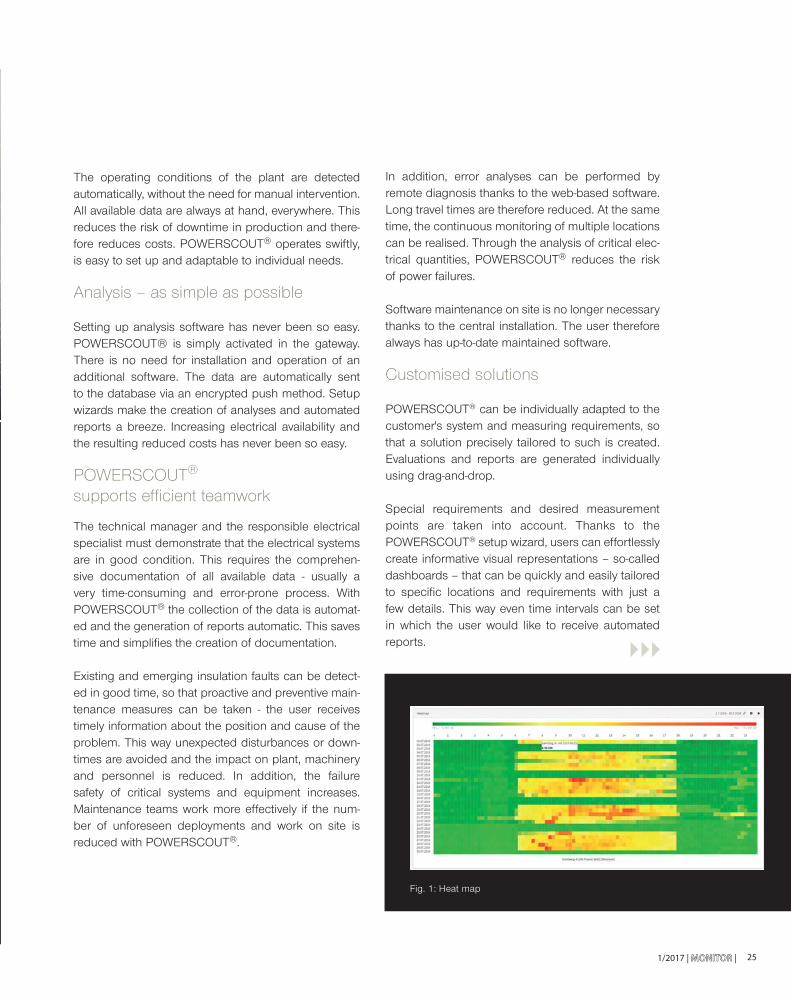
Fig. 1: Heat mapFig 1: Heat map
In addition, error analyses can be performed by remote diagnosis thanks to the web-based software. Long travel times are therefore reduced. At the same time, the continuous monitoring of multiple locations can be realised. Through the analysis of critical elec-trical quantities, POWERSCOUT® reduces the risk of power failures.
Software maintenance on site is no longer necessary thanks to the central installation. The user therefore always has up-to-date maintained software.
Customised solutions
POWERSCOUT® can be individually adapted to the customer's system and measuring requirements, so that a solution precisely tailored to such is created. Evaluations and reports are generated individually using drag-and-drop.
Special requirements and desired measurement points are taken into account. Thanks to the POWERSCOUT® setup wizard, users can effortlessly create informative visual representations – so-called dashboards – that can be quickly and easily tailored to specifi c locations and requirements with just a few details. This way even time intervals can be set in which the user would like to receive automated reports.
The operating conditions of the plant are detected automatically, without the need for manual intervention. All available data are always at hand, everywhere. This reduces the risk of downtime in production and there-fore reduces costs. POWERSCOUT® operates swiftly, is easy to set up and adaptable to individual needs.
Analysis – as simple as possible
Setting up analysis software has never been so easy. POWERSCOUT® is simply activated in the gateway. There is no need for installation and operation of an additional software. The data are automatically sent to the database via an encrypted push method. Setup wizards make the creation of analyses and automated reports a breeze. Increasing electrical availability and the resulting reduced costs has never been so easy.
POWERSCOUT® supports effi cient teamwork
The technical manager and the responsible electrical specialist must demonstrate that the electrical systems are in good condition. This requires the comprehen-sive documentation of all available data - usually a very time-consuming and error-prone process. With POWERSCOUT® the collection of the data is automat-ed and the generation of reports automatic. This saves time and simplifi es the creation of documentation.
Existing and emerging insulation faults can be detect-ed in good time, so that proactive and preventive main-tenance measures can be taken - the user receives timely information about the position and cause of the problem. This way unexpected disturbances or down-times are avoided and the impact on plant, machinery and personnel is reduced. In addition, the failure safety of critical systems and equipment increases. Maintenance teams work more effectively if the num-ber of unforeseen deployments and work on site is reduced with POWERSCOUT®.
| MONITORMONITOR | 1/201726
INFO
The POWERSCOUT® website
can be found at:
powerscout.bender.de
You can make direct contact there to obtain
your personal access.
INNOVATIVE P RO D U C TS
PO
WE
RS
CO
UT
®
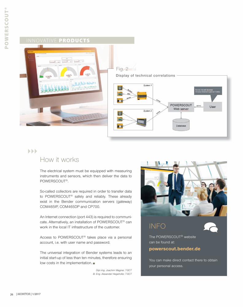
Fig. 2Display of technical correlations
Dipl.-Ing. Joachim Wagner, T-SCT
B. Eng. Alexander Hegehofer, T-SCT
How it worksThe electrical system must be equipped with measuring instruments and sensors, which then deliver the data to POWERSCOUT®.
So-called collectors are required in order to transfer data to POWERSCOUT® safely and reliably. These already exist in the Bender communication servers (gateway) COM465IP, COM465DP and CP700.
An Internet connection (port 443) is required to communi-cate. Alternatively, an installation of POWERSCOUT® can work in the local IT infrastructure of the customer.
Access to POWERSCOUT® takes place via a personal account, i.e. with user name and password.
The universal integration of Bender systems leads to an initial start-up of less than ten minutes, therefore ensuring low costs in the implementation.

T E C H N I C A L A P P L I C AT I O N
Lisa Hudson, Bender UK
271/2017 | MONITORMONITOR |
Critical role for Bender at new Royal Liverpool Hospital
Bender UK has been awarded a contract to supply critical care power systems
and hygienic touch-screen theatre control panels with PACS x-ray and scan viewing
screens for the 18 operating theatres at the new Royal Liverpool University Hospital.
performance means that Bender UK is able to make a sig-nifi cant contribution to major projects in terms of meeting challenging deadlines and adding value at the specifi ca-tion and installation stages.”
Construction of the new 12-storey hospital alongside the existing building on Prescot Street began in February 2014. It will contain 646 beds, all in individual en-suite rooms, spread across 23 wards, a 40-bed critical care unit and 18 operating theatres.
The Royal Liverpool University Hospital is the biggest and busiest hospital in Merseyside. Each year the hospital provides care and treatment for around 93,500 emer-gency patients and the Trust sees more than 117,000 day case and inpatients and over 6000,000 outpatients attendances.
Once the new Royal Liverpool University Hospital is constructed, the existing hospital will be demolished. In its place, there are plans to develop the Liverpool Health Campus, which will consist of 200,000 square feet of space, attracting life sciences, biomedical research com-panies and health organisations.
Once the project is completed, the Bender UK service team will provide annual maintenance, 24/7 technical support and a rapid response call-out service 365 days of the year to ensure the continuous supply of power to critical care areas.
The UK market leader in electrical safety systems, Ulverston-based Bender UK is providing equipment that will deliver advanced protection and also provide suffi cient capacity to ‘future proof’ the hospital for the anticipated expansion of power requirements.
The landmark £335 million redevelopment of the Royal Liverpool University Hospital will create the largest hospital in England when it is completed in 2017. It is part of the Royal Liverpool and Broadgreen University Hospitals NHS Trust.
Bender UK Managing Director Gareth Brunton explains: “Our vast experience of hospital electrical systems and a proven track record in delivering advanced technical
| MONITORMONITOR | 1/201728
TECHNICAL APPLICATION
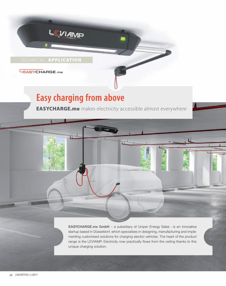
Easy charging from above EASYCHARGE.me makes electricity accessible almost everywhere
EASYCHARGE.me GmbH – a subsidiary of Uniper Energy Sales - is an innovative startup based in Düsseldorf, which specialises in designing, manufacturing and imple-menting customised solutions for charging electric vehicles. The heart of the product range is the LEVIAMP. Electricity now practically fl ows from the ceiling thanks to this unique charging solution.

1/2017 | MONITORMONITOR | 29
The future starts today
The core of the LEVIAMP ceiling charging solution is the Charge Controller CC612 from Bender Co. KG. Due to its compact design, the controller integrates seamlessly into the design of the LEVIAMP. The CC612 boasts sophisticat-ed technology and all requirements of modern charging control are more than satisfi ed. Various back-end systems can be easily connected via the open communication pro-tocol. The support of mobile 2.5 Edge and 3G UMTS net-works guarantees comprehensive reception services and high data transmission. WiFi interfaces provide access to home applications. Local confi guration and software updates can be conveniently made via other interfaces. With Power Line Communication (PLC), the Charge Controller already has pioneering technology to automate 'Plug & Charge' charging management or 'Vehicle-to-Grid (V2G)' applications. The LEVIAMP therefore combines outstanding technology with modern design.
Electric mobility made comfortable
Electric mobility has long become an important part of our sustainable and climate-friendly transport system. Accordingly, the German Federal Government is committed to making Germany the leading market for electric mobility. A nationwide expansion of charging infrastructure for a broad introduction of electric cars is an important contribution to the success of the ener-gy revolution. With future-orientated device charging solutions, EASYCHARGE.me makes the spread of this form of mobility easier and therefore permits rapid deployment for municipal, commercial and residential users. EASYCHARGE.me continuously works on the improvement of charging infrastructures - with the aim of signifi cantly increasing the acceptance of electric mobility.
Energy from above
The LEVIAMP ceiling-charging station really does not differ too much optically from a ceiling light in a garage. It combines premium materials with unique mobile technology: The 180 degree-swivelling charging arm, on which the socket is located, comfort-ably and fl exibly reaches all charging devices on all types of electric vehicles. After use, it can again easily and compactly fold together under the ceiling. A time-lessly elegant design and high-quality workmanship harmoniously fi t into new and challenging construc-tion projects. The charging solution from the ceiling is not only functional, but the highest architectural and aesthetic demands are also visually satisfi ed.
The LEVIAMP is even usable where conventional charging solutions are diffi cult to install. For example, in the central parking rows in large parking garages. With central mounting between two adjacent parking spaces, even two cars can be charged in a very space- and cost-saving way. Depending on the requirements, the LEVIAMP can be simply operated via household power (3.7 kW) and via a three-phase connection with a medium (11 kW) or higher charging power (22 kW). An integrated LED light ex works provides optimal lighting when charging.
The LEVIAMP does not just reliably supply
closed parking spaces with electricity. The
charging device can also be used in private
garages, in industrial companies, hotel chains,
in retail or in operation in aboveground and
underground parking garages. Artur Sychov, CEO
EASYCHARGE.me GmbH

| MONITORMONITOR | 1/201730
Malaysia’s First Electric Bus
development of the monorail construction in Mumbai and Brazil (Scomi Gen2 Monorail) in 2006.
With the experience in handling the composite struc-tures with Scomi Gen 2 Monorail, Sync R&D is apply-ing the same knowledge and experience in designing the electric bus with the same structure. Electric Bus Innovation Malaysia, EBIM as they named it, will be the fi rst Composite Monocoque Electric City Bus in Malaysia and the ASEAN region. It is designed with a unique fea-ture or component that offers specifi c advantages besides the light composite structure.
Sync R&D developed the idea to design an elec-tric city bus in 2011. The young company, found-ed in 2006, had realised that the demand for elec-tric vehicles (EVs) is growing around the world fairly rapidly and decided to break through the EV's market. The focus was particularly placed on the electric bus, a market segment that back then was still monopolized by countries like China.
Sync R&D has been involved in various technol-ogy development projects over the last 10 years. One of the most remarkable projects was the
If you have not heard, the fi rst electric bus assembled locally will be on the
streets of Kuala Lumpur in 2017! The astounding fi rst-ever electric bus is currently
handled by an Engineering Solution and R&D based company, Sync R&D.
EBIM (Electric Bus Innovation Malaysia) has included one of the key
electronic components from Bender that is the ISOMETER®
IR155-3204 with professional technical support provided by
Eetarp Engineering (M) Sdn Bhd.
y
TECHNICAL APPLICATION
Environmentally friendly innovation
1/2017 | MONITORMONITOR | 31
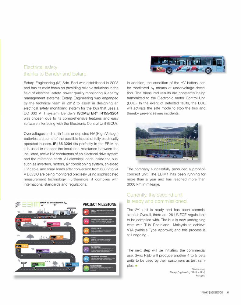
Electrical safety thanks to Bender and Eetarp
Eetarp Engineering (M) Sdn. Bhd was established in 2003 and has its main focus on providing reliable solutions in the fi eld of electrical safety, power quality monitoring & energy management systems. Eetarp Engineering was enganged by the technical team in 2012 to assist in designing an electrical safety monitoring system for the bus that uses a DC 600 V IT system. Bender’s ISOMETER® IR155-3204 was chosen due to its comprehensive features and easy software interfacing with the Electronic Control Unit (ECU).
Overvoltages and earth faults or depleted HV (High Voltage) batteries are some of the possible issues of fully electrically operated busses. IR155-3204 fi ts perfectly in the EBIM as it is used to monitor the insulation resistance between the insulated, active HV conductors of an electrical drive system and the reference earth. All electrical loads inside the bus, such as inverters, motors, air conditioning system, shielded HV cable, and small loads after conversion from 600 V to 24 V DC/DC are being monitored precisely using sophisticated measurement technology. Furthermore, it complies with international standards and regulations.
In addition, the condition of the HV battery can be monitored by means of undervoltage detec-tion. The measured results are constantly being transmitted to the Electronic motor Control Unit (ECU). In the event of detected faults, the ECU will activate the safe mode to stop the bus and thereby prevent severe incidents.
The company successfully produced a proof-of-concept unit. The EBIM1 has been running for more than a year and has reached more than 3000 km in mileage.
Currently, the second unit is ready and commissioned.
The 2nd unit is ready and has been commis-sioned. Overall, there are 26 UNECE regulations to be complied with. The bus is now undergoing tests with TUV Rheinland Malaysia to achieve VTA (Vehicle Type Approval) and this process is still ongoing.
The next step will be initiating the commercial use: Sync R&D will produce another 4 to 5 beta units to be used by their customers as test sam-ples.
Kevin LeongEetarp Engineering (M) Sdn Bhd,
Malaysia
e condition of the HV battery can by means f d l

| MONITORMONITOR | 1/201732
and they are scheduled to meet again at the next MotoStudent competition in the 2017/18 season.
In addition to the MotoStudent Petrol category, the competition this year was extended to include a MotoStudent Electric category in which entire-ly electrically powered motorbikes went to the starting line. der ersten Phase des Wettbewerbs
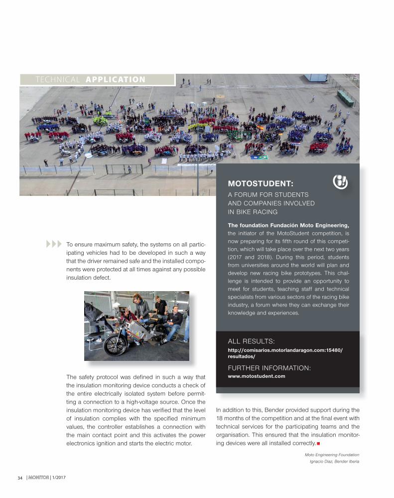
The fi rst week of October was charged with a positive sport-ing atmosphere. Over the four days of this event, more than 600 engineering students from 52 European universities in ten different countries measured themselves against each other in both technical and sporting terms, the culminating point of the development of their prototype racing bikes. The prototypes presented at MotorLand Aragón are the result of 18 months of engineering work at the various universities,
TECHNICAL APPLICATION
Fourth 'MotoStudent' race at MotorLand Aragón in Spain
The prototype racing bikes developed by students over the last
18 months were put to the test and evaluated on the MotorLand
motorbike race track at Aragón, Spain between 5 and 9 October 2016
in the final of the MotoStudent competition.
1/2017 | MONITORMONITOR | 33
fi nal race. The winners of phase MS2 in the MotoStudent Electric category were the motorbikes developed by teams 2WheelsPoliTO (University of Turin) and MotoSpirit UPC (Polytechnic University of Catalonia).
Bender and MotoStudent Electric
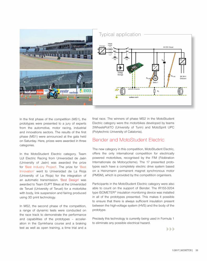
The new category in this competition, MotoStudent Electric, offers the only international competition for electrically powered motorbikes, recognised by the FIM (Fédération Internationale de Motocyclisme). The 17 presented proto-types each have a completely electric drive system based on a Heinzmann permanent magnet synchronous motor (PMSM), which is provided by the competition organisers.
Participants in the MotoStudent Electric category were also able to count on the support of Bender. The IR155-3204 type ISOMETER® insulation monitoring device was installed in all of the prototypes presented. This makes it possible to ensure that there is always suffi cient insulation present between the high-voltage system (HVS) and the body of the prototype.
Precisely this technology is currently being used in Formula 1 to eliminate any possible electrical hazard.
In the fi rst phase of the competition (MS1), the prototypes were presented to a jury of experts from the automotive, motor racing, industrial and innovations sectors. The results of the fi rst phase (MS1) were announced at the gala held on Saturday. Here, prizes were awarded in three categories.
In the MotoStudent Electric category, Team UJI Electric Racing from Universidad de Jaén (University of Jaén) was awarded the prize for 'Best Industry Project'. The prize for 'Best Innovation' went to Universidad de La Rioja (University of La Rioja) for the integration of an automatic transmission. 'Best Design' was awarded to Team EUPT Bikes at the Universidad de Teruel (University of Teruel) for a motorbike with body, link suspension and fairing produced using 3D print technology.
In MS2, the second phase of the competition, a range of dynamic tests were conducted on the race track to demonstrate the performance and capabilities of the prototypes – acceler-ation in the Gymkhana course and a braking test as well as open training, a time trial and a
Typical application
vehicle chassis
| MONITORMONITOR | 1/201734
TECHNICAL APPLICATION
To ensure maximum safety, the systems on all partic-ipating vehicles had to be developed in such a way that the driver remained safe and the installed compo-nents were protected at all times against any possible insulation defect.
The safety protocol was defi ned in such a way that the insulation monitoring device conducts a check of the entire electrically isolated system before permit-ting a connection to a high-voltage source. Once the insulation monitoring device has verifi ed that the level of insulation complies with the specifi ed minimum values, the controller establishes a connection with the main contact point and this activates the power electronics ignition and starts the electric motor.
In addition to this, Bender provided support during the 18 months of the competition and at the fi nal event with technical services for the participating teams and the organisation. This ensured that the insulation monitor-ing devices were all installed correctly.
Moto Engineering Foundation
Ignacio Diaz, Bender Iberia
MOTOSTUDENT: A FORUM FOR STUDENTS AND COMPANIES INVOLVED IN BIKE RACING
The foundation Fundación Moto Engineering, the initiator of the MotoStudent competition, is now preparing for its fi fth round of this competi-tion, which will take place over the next two years (2017 and 2018). During this period, students from universities around the world will plan and develop new racing bike prototypes. This chal-lenge is intended to provide an opportunity to meet for students, teaching staff and technical specialists from various sectors of the racing bike industry, a forum where they can exchange their knowledge and experiences.
FURTHER INFORMATION:www.motostudent.com
ALL RESULTS:http://comisarios.motorlandaragon.com:15480/resultados/
1/2017 | MONITORMONITOR | 35
B E N D E R I N H O U S E
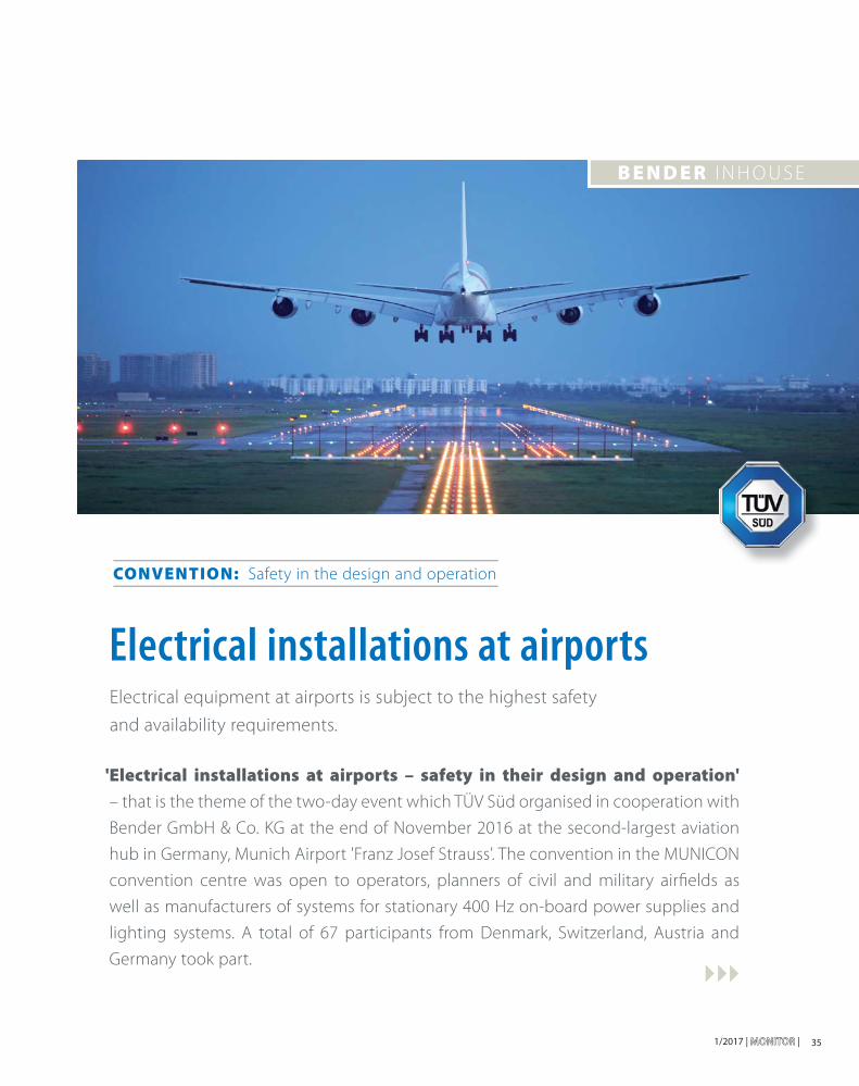
Electrical installations at airportsElectrical equipment at airports is subject to the highest safety
and availability requirements.
' Electrical installations at airports – safety in their design and operation'
– that is the theme of the two-day event which TÜV Süd organised in cooperation with
Bender GmbH & Co. KG at the end of November 2016 at the second-largest aviation
hub in Germany, Munich Airport 'Franz Josef Strauss'. The convention in the MUNICON
convention centre was open to operators, planners of civil and military airfi elds as
well as manufacturers of systems for stationary 400 Hz on-board power supplies and
lighting systems. A total of 67 participants from Denmark, Switzerland, Austria and
Germany took part.
CONVENTION: Safety in the design and operation
36 | MONITORMONITOR | 1/2017
docking station to the aircraft to extreme weather conditions as well as chemical, mechanical and electrical infl uences. Continuous monitoring of the supply lines of the 960 V/400 Hz transmis-sion system is therefore required. Bender uses an ISOMETER® type iso1685PW-425 insulation monitoring device for the monitoring (distance between the central converter and the gate boxes). This device provides safe earth fault monitoring of the supply lines up to the gate boxes including the selective fault detection of a faulty outgoing feeder.
The monitoring of the cable path from the gate box to the plane represents a further technical challenge for the operator. Various solutions
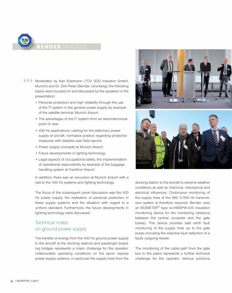
Moderated by Karl Edelmann (TÜV SÜD Industrie GmbH, Munich) and Dr. Dirk Pieler (Bender, Grünberg), the following topics were focused on and discussed by the speakers in the presentation:
• Personal protection and high reliability through the use of the IT system in the general power supply by example of the satellite terminal, Munich Airport
• The advantages of the IT system from an electrotechnical point of view
• 400 Hz applications, cabling for the stationary power supply of aircraft, normative position regarding protective measures with detailed user fi eld reports
• Power supply concepts at Munich Airport
• Future developments in lighting technology
• Legal aspects of occupational safety, the implementation of operational responsibility by example of the baggage handling system at Frankfurt Airport.
In addition, there was an excursion at Munich Airport with a visit to the 400 Hz systems and lighting technology.
The focus of the subsequent panel discussion was the 400 Hz power supply, the realisation of personal protection in these supply systems and the situation with regard to a uniform standard. Furthermore, the future developments in lighting technology were discussed.
Technical notes on ground power supply
The transfer of energy from the 400 Hz ground power supply to the aircraft at the docking stations and passenger board-ing bridges represents a major challenge for the operator. Unfavourable operating conditions on the apron expose power supply systems, in particular the supply lines from the
B E N D E R I N H O U S E
1/2017 | MONITORMONITOR | 37
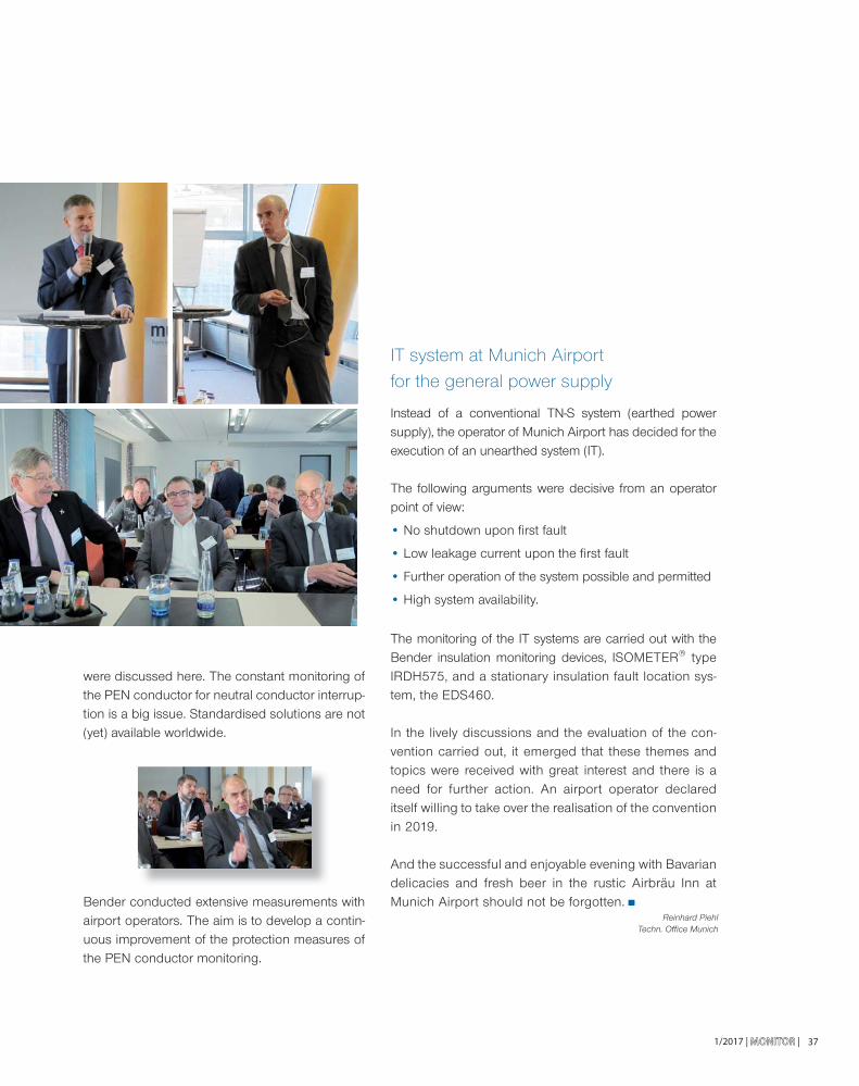
IT system at Munich Airport for the general power supply
Instead of a conventional TN-S system (earthed power supply), the operator of Munich Airport has decided for the execution of an unearthed system (IT).
The following arguments were decisive from an operator point of view:
• No shutdown upon fi rst fault
• Low leakage current upon the fi rst fault
• Further operation of the system possible and permitted
• High system availability.
The monitoring of the IT systems are carried out with the Bender insulation monitoring devices, ISOMETER® type IRDH575, and a stationary insulation fault location sys-tem, the EDS460.
In the lively discussions and the evaluation of the con-vention carried out, it emerged that these themes and topics were received with great interest and there is a need for further action. An airport operator declared itself willing to take over the realisation of the convention in 2019.
And the successful and enjoyable evening with Bavarian delicacies and fresh beer in the rustic Airbräu Inn at Munich Airport should not be forgotten.
were discussed here. The constant monitoring of the PEN conductor for neutral conductor interrup-tion is a big issue. Standardised solutions are not (yet) available worldwide.
Bender conducted extensive measurements with airport operators. The aim is to develop a contin-uous improvement of the protection measures of the PEN conductor monitoring.
Reinhard PiehlTechn. Offi ce Munich

| MONITORMONITOR | 1/201738
equipped with Bender continuous monitoring technology to enable predictive maintenance of the buildings electri-cal infrastructure.
Managing Director Gareth Brunton explains: “Our pur-pose-built facility represents a major investment by Bender Group in its UK operation. It provides superb facilities for the training and 24/7 technical support provided to cus-tomers across the UK and Ireland.
Bender UK has doubled in size since 2010 driven by its ability to deliver bespoke engineered solutions and an advanced service and support capability for the medical sector.
Bender UK has moved into a new purpose-built headquarters in Ulverston, Cumbria. The 2000 m² building accommodates offi ces, large conference facilities, warehousing, training and customer demonstration areas.
The new facility and service centre is designed to accommodate continued growth and to be a showpiece for the company’s advanced technology solutions. Bender surgical lighting, touch screen the-atre control panels and other critical care medical solutions will be permanently on display for client demonstrations and training. The facility is also
B E N D E R I N H O U S E
Bender branch in UK moves into new building
Bender UK shows
the latest safety technology at the new site
in addition to an impressive new facility
Bender current transformers

391/2017 | MONITORMONITOR |
Performance is critical
Power supply performance and resilience is critical to health trusts and the managers of clinical facilities to operate safely and cost effectively. Bender’s continuous intelligent monitoring systems provide a comprehensive overview of a hospital’s power network, enabling energy costs to be identifi ed and reduced, while protecting criti-cal power systems and achieving maximum availability of electrical supply. It also enables periodic inspection and testing without switch off.
Bender’s Residual Current Monitoring (RCM) and Power Energy Metering (PEM) is incorporated into the new Bender UK facility. This includes a 12-channel RCMS460 which monitors the main distribution board, while RCMS150 devices monitor local distribution within the building across offi ces and meeting rooms, and critical areas such as the plant room and air conditioning system.
The installed Bender devices monitor the frequency, current, power performance, energy consumption and harmonics to present a comprehensive picture of the building’s power infrastructure. The combination of power monitoring and electrical safety delivers an integrated solution which provides early warning of faults or failure for all critical aspects of the buildings electrical infrastruc-ture.
Monitored by POWERSCOUT®
The new facility is connected to POWERSCOUT® the latest Bender software development which delivers comprehensive analysis, reporting and live data on the status of the building. This smart cloud based technology produces reports from the residual current monitoring and power quality metering technology onsite, which enables pro-active analysis, fault fi nding and maintenance.
This solution is particularly appropriate for all sizes of healthcare facilities where the electrical infrastructure cannot afford to fail, and where estates personnel would benefi t from remote monitoring technology. Bender’s Powerscout® software combined with resid-ual current monitoring solutions can be a vital tool for managing and maintaining healthcare estates.
Bender’s new UK headquarters is the perfect show-case to demonstrate equipment and technology capa-bilities.
Lisa Hudson, Bender UK
Residual current monitoring device RCMS150 installed
in a distribution board
Technical support analysing Powerscout® software
„This solution is particularly
appropriate for all sizes of healthcare facilities
where the electrical infrastructure
cannot aff ord to fail ...”
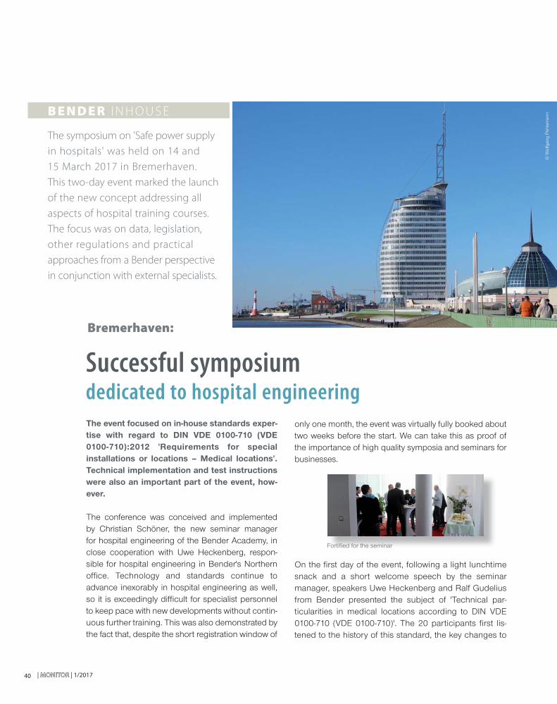
| MONITORMONITOR | 1/201740
Successful symposium dedicated to hospital engineering
only one month, the event was virtually fully booked about two weeks before the start. We can take this as proof of the importance of high quality symposia and seminars for businesses.
On the fi rst day of the event, following a light lunchtime snack and a short welcome speech by the seminar manager, speakers Uwe Heckenberg and Ralf Gudelius from Bender presented the subject of 'Technical par-ticularities in medical locations according to DIN VDE 0100-710 (VDE 0100-710)'. The 20 participants fi rst lis-tened to the history of this standard, the key changes to
The event focused on in-house standards exper-tise with regard to DIN VDE 0100-710 (VDE 0100-710):2012 'Requirements for special installations or locations – Medical locations'. Technical implementation and test instructions were also an important part of the event, how-ever.
The conference was conceived and implemented by Christian Schöner, the new seminar manager for hospital engineering of the Bender Academy, in close cooperation with Uwe Heckenberg, respon-sible for hospital engineering in Bender's Northern offi ce. Technology and standards continue to advance inexorably in hospital engineering as well, so it is exceedingly diffi cult for specialist personnel to keep pace with new developments without contin-uous further training. This was also demonstrated by the fact that, despite the short registration window of
Bremerhaven:
The symposium on 'Safe power supply
in hospitals' was held on 14 and
15 March 2017 in Bremerhaven.
This two-day event marked the launch
of the new concept addressing all
aspects of hospital training courses.
The focus was on data, legislation,
other regulations and practical
approaches from a Bender perspective
in conjunction with external specialists.
Fortifi ed for the seminarForortifitifieded fofor tr thehe semseminainarr©
Wol
fgan
g P
ehle
man
nB E N D E R I N H O U S E
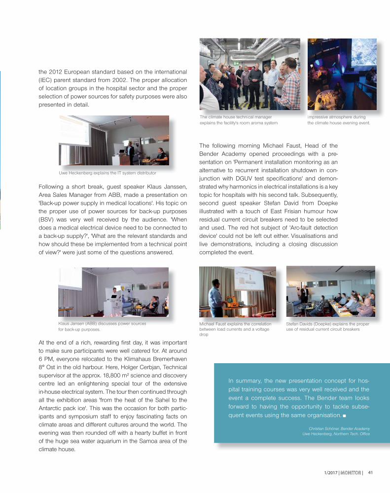
1/2017 | MONITORMONITOR | 41
the 2012 European standard based on the international (IEC) parent standard from 2002. The proper allocation of location groups in the hospital sector and the proper selection of power sources for safety purposes were also presented in detail.
Following a short break, guest speaker Klaus Janssen, Area Sales Manager from ABB, made a presentation on 'Back-up power supply in medical locations'. His topic on the proper use of power sources for back-up purposes (BSV) was very well received by the audience. 'When does a medical electrical device need to be connected to a back-up supply?', 'What are the relevant standards and how should these be implemented from a technical point of view?' were just some of the questions answered.
At the end of a rich, rewarding fi rst day, it was important to make sure participants were well catered for. At around 6 PM, everyone relocated to the Klimahaus Bremerhaven 8° Ost in the old harbour. Here, Holger Cerbjan, Technical supervisor at the approx. 18,800 m² science and discovery centre led an enlightening special tour of the extensive in-house electrical system. The tour then continued through all the exhibition areas 'from the heat of the Sahel to the Antarctic pack ice'. This was the occasion for both partic-ipants and symposium staff to enjoy fascinating facts on climate areas and different cultures around the world. The evening was then rounded off with a hearty buffet in front of the huge sea water aquarium in the Samoa area of the climate house.
The following morning Michael Faust, Head of the Bender Academy opened proceedings with a pre-sentation on 'Permanent installation monitoring as an alternative to recurrent installation shutdown in con-junction with DGUV test specifi cations' and demon-strated why harmonics in electrical installations is a key topic for hospitals with his second talk. Subsequently, second guest speaker Stefan David from Doepke illustrated with a touch of East Frisian humour how residual current circuit breakers need to be selected and used. The red hot subject of 'Arc-fault detection device' could not be left out either. Visualisations and live demonstrations, including a closing discussion completed the event.
Christian Schöner, Bender AcademyUwe Heckenberg, Northern Tech. Offi ce
In summary, the new presentation concept for hos-pital training courses was very well received and the event a complete success. The Bender team looks forward to having the opportunity to tackle subse-quent events using the same organisation.
Uwe Heckenberg explains the IT system distributorUwewe HeHeckeckenbenbergrg expexplailainsns thethe ITIT sysystestem dm dististribributoutorr
Klaus Jansen (ABB) discusses power sources for back-up purposes.KlaKlausus JanJansensen (A(ABB)BB) didiscuscussesses ps poweower sr sourourcesces
The climate house technical manager explains the facility's room aroma system
Impressive atmosphere during the climate house evening event.
Michael Faust explains the correlation between load currents and a voltage drop
Stefan Davids (Doepke) explains the proper use of residual current circuit breakersSteStefanfan DaDavidvids (s (DoeDoepkepke) e) explxplainains ts thehe proproperper
TheThe clclimaimatete houhousese tectechnihnicalcal mamanagnagerer Impmpresressivsive ae atmotmosphsphereere dudurinringg
MicMichaehael Fl Fausaust et explxplainains ts thehe corcorrelrelatiationon
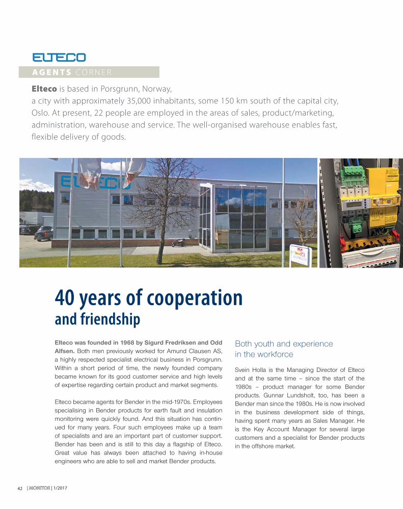
| MONITORMONITOR | 1/201742
Both youth and experience in the workforce
Svein Holla is the Managing Director of Elteco and at the same time – since the start of the 1980s – product manager for some Bender products. Gunnar Lundsholt, too, has been a Bender man since the 1980s. He is now involved in the business development side of things, having spent many years as Sales Manager. He is the Key Account Manager for several large customers and a specialist for Bender products in the offshore market.
Elteco was founded in 1968 by Sigurd Fredriksen and Odd Alfsen. Both men previously worked for Amund Clausen AS, a highly respected specialist electrical business in Porsgrunn. Within a short period of time, the newly founded company became known for its good customer service and high levels of expertise regarding certain product and market segments.
Elteco became agents for Bender in the mid-1970s. Employees specialising in Bender products for earth fault and insulation monitoring were quickly found. And this situation has contin-ued for many years. Four such employees make up a team of specialists and are an important part of customer support. Bender has been and is still to this day a fl agship of Elteco. Great value has always been attached to having in-house engineers who are able to sell and market Bender products.
40 years of cooperation and friendship
Elteco is based in Porsgrunn, Norway,
a city with approximately 35,000 inhabitants, some 150 km south of the capital city,
Oslo. At present, 22 people are employed in the areas of sales, product/marketing,
administration, warehouse and service. The well-organised warehouse enables fast,
flexible delivery of goods.
A G E N T S C O R N E R
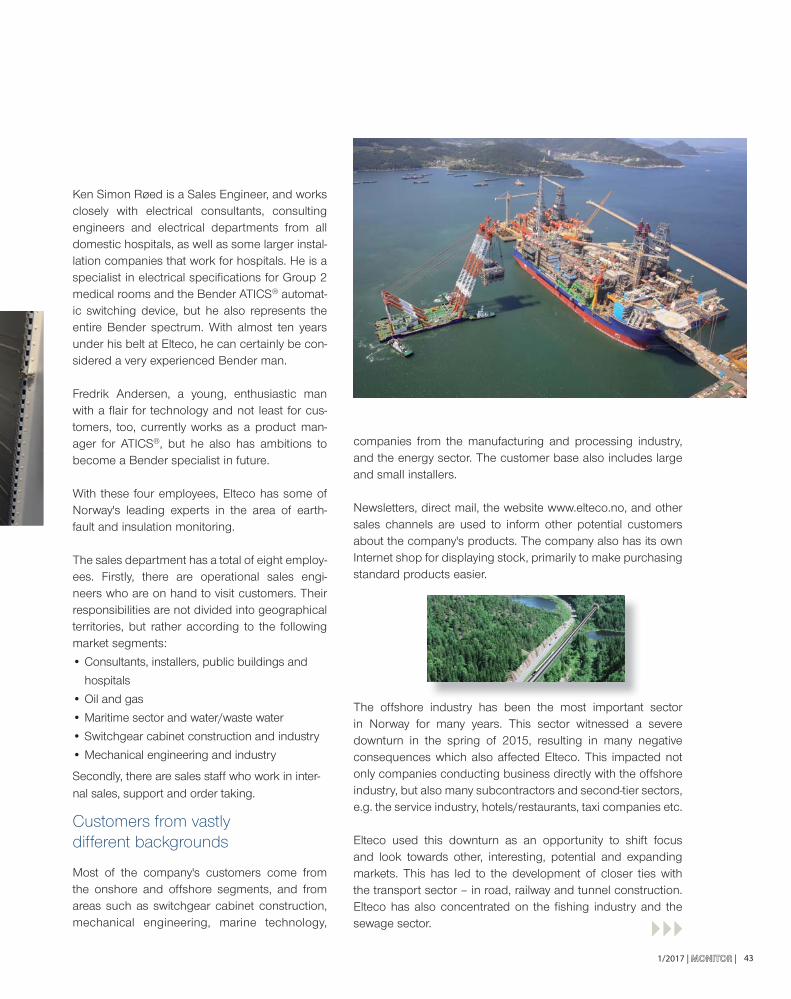
1/2017 | MONITORMONITOR | 43
companies from the manufacturing and processing industry, and the energy sector. The customer base also includes large and small installers.
Newsletters, direct mail, the website www.elteco.no, and other sales channels are used to inform other potential customers about the company's products. The company also has its own Internet shop for displaying stock, primarily to make purchasing standard products easier.
The offshore industry has been the most important sector in Norway for many years. This sector witnessed a severe downturn in the spring of 2015, resulting in many negative consequences which also affected Elteco. This impacted not only companies conducting business directly with the offshore industry, but also many subcontractors and second-tier sectors, e.g. the service industry, hotels/restaurants, taxi companies etc.
Elteco used this downturn as an opportunity to shift focus and look towards other, interesting, potential and expanding markets. This has led to the development of closer ties with the transport sector – in road, railway and tunnel construction. Elteco has also concentrated on the fi shing industry and the sewage sector.
Ken Simon Røed is a Sales Engineer, and works closely with electrical consultants, consulting engineers and electrical departments from all domestic hospitals, as well as some larger instal-lation companies that work for hospitals. He is a specialist in electrical specifi cations for Group 2 medical rooms and the Bender ATICS® automat-ic switching device, but he also represents the entire Bender spectrum. With almost ten years under his belt at Elteco, he can certainly be con-sidered a very experienced Bender man.
Fredrik Andersen, a young, enthusiastic man with a fl air for technology and not least for cus-tomers, too, currently works as a product man-ager for ATICS®, but he also has ambitions to become a Bender specialist in future.
With these four employees, Elteco has some of Norway's leading experts in the area of earth-fault and insulation monitoring.
The sales department has a total of eight employ-ees. Firstly, there are operational sales engi-neers who are on hand to visit customers. Their responsibilities are not divided into geographical territories, but rather according to the following market segments:
• Consultants, installers, public buildings and
hospitals
• Oil and gas
• Maritime sector and water/waste water
• Switchgear cabinet construction and industry
• Mechanical engineering and industry
Secondly, there are sales staff who work in inter-nal sales, support and order taking.
Customers from vastly different backgrounds
Most of the company's customers come from the onshore and offshore segments, and from areas such as switchgear cabinet construction, mechanical engineering, marine technology,
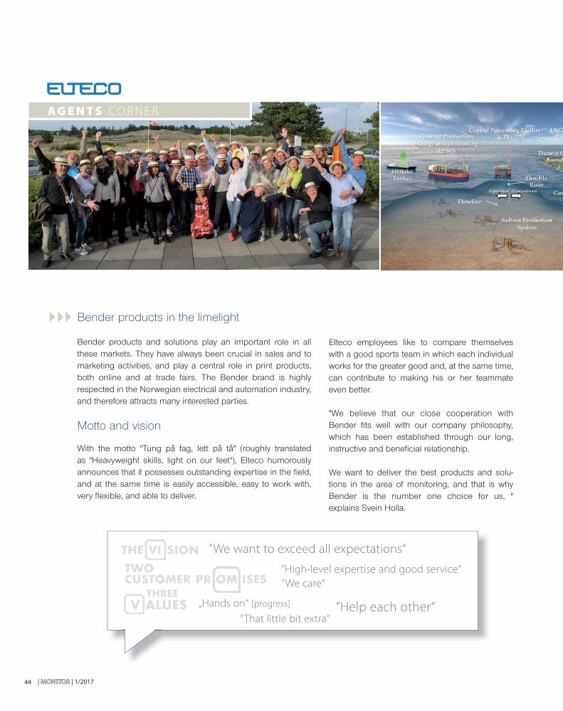
| MONITORMONITOR | 1/201744
Bender products in the limelight
Bender products and solutions play an important role in all these markets. They have always been crucial in sales and to marketing activities, and play a central role in print products, both online and at trade fairs. The Bender brand is highly respected in the Norwegian electrical and automation industry, and therefore attracts many interested parties.
Motto and vision
With the motto "Tung på fag, lett på tå" (roughly translated as "Heavyweight skills, light on our feet"), Elteco humorously announces that it possesses outstanding expertise in the fi eld, and at the same time is easily accessible, easy to work with, very fl exible, and able to deliver.
Elteco employees like to compare themselves with a good sports team in which each individual works for the greater good and, at the same time, can contribute to making his or her teammate even better.
"We believe that our close cooperation with Bender fi ts well with our company philosophy, which has been established through our long, instructive and benefi cial relationship.
We want to deliver the best products and solu-tions in the area of monitoring, and that is why Bender is the number one choice for us, " explains Svein Holla.
”We want to exceed all expectations“
”High-level expertise and good service“
”We care“
„Hands on“ [progress]
”That little bit extra“”Help each other“
THE VI SION
CUSTOMER PR OM ISESTWO
V ALUESTHREE
A G E N T S C O R N E R
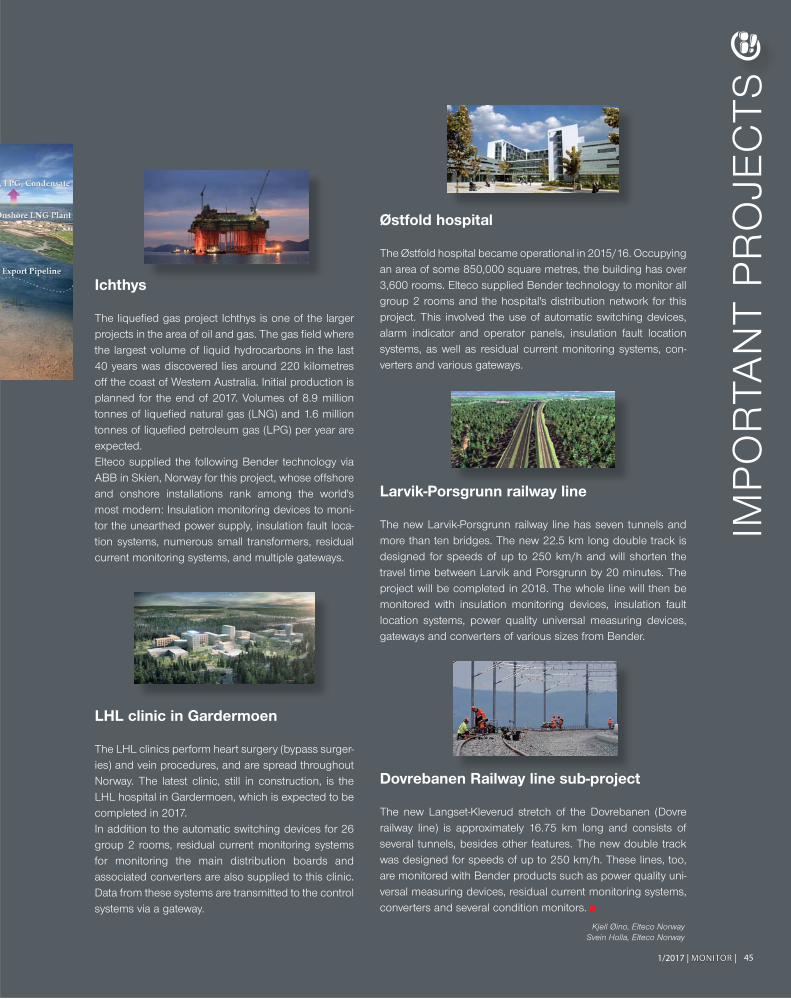
1/2017 | MONITORMONITOR | 45
Kjell Øino, Elteco NorwaySvein Holla, Elteco Norway
Kjell Ø
IMP
OR
TAN
T P
RO
JEC
TS
Ichthys
The liquefi ed gas project Ichthys is one of the larger projects in the area of oil and gas. The gas fi eld where the largest volume of liquid hydrocarbons in the last 40 years was discovered lies around 220 kilometres off the coast of Western Australia. Initial production is planned for the end of 2017. Volumes of 8.9 million tonnes of liquefi ed natural gas (LNG) and 1.6 million tonnes of liquefi ed petroleum gas (LPG) per year are expected.Elteco supplied the following Bender technology via ABB in Skien, Norway for this project, whose offshore and onshore installations rank among the world's most modern: Insulation monitoring devices to moni-tor the unearthed power supply, insulation fault loca-tion systems, numerous small transformers, residual current monitoring systems, and multiple gateways.
LHL clinic in Gardermoen
The LHL clinics perform heart surgery (bypass surger-ies) and vein procedures, and are spread throughout Norway. The latest clinic, still in construction, is the LHL hospital in Gardermoen, which is expected to be completed in 2017.In addition to the automatic switching devices for 26 group 2 rooms, residual current monitoring systems for monitoring the main distribution boards and associated converters are also supplied to this clinic. Data from these systems are transmitted to the control systems via a gateway.
Østfold hospital
The Østfold hospital became operational in 2015/16. Occupying an area of some 850,000 square metres, the building has over 3,600 rooms. Elteco supplied Bender technology to monitor all group 2 rooms and the hospital's distribution network for this project. This involved the use of automatic switching devices, alarm indicator and operator panels, insulation fault location systems, as well as residual current monitoring systems, con-verters and various gateways.
Larvik-Porsgrunn railway line
The new Larvik-Porsgrunn railway line has seven tunnels and more than ten bridges. The new 22.5 km long double track is designed for speeds of up to 250 km/h and will shorten the travel time between Larvik and Porsgrunn by 20 minutes. The project will be completed in 2018. The whole line will then be monitored with insulation monitoring devices, insulation fault location systems, power quality universal measuring devices, gateways and converters of various sizes from Bender.
Dovrebanen Railway line sub-project
The new Langset-Kleverud stretch of the Dovrebanen (Dovre railway line) is approximately 16.75 km long and consists of several tunnels, besides other features. The new double track was designed for speeds of up to 250 km/h. These lines, too, are monitored with Bender products such as power quality uni-versal measuring devices, residual current monitoring systems, converters and several condition monitors.
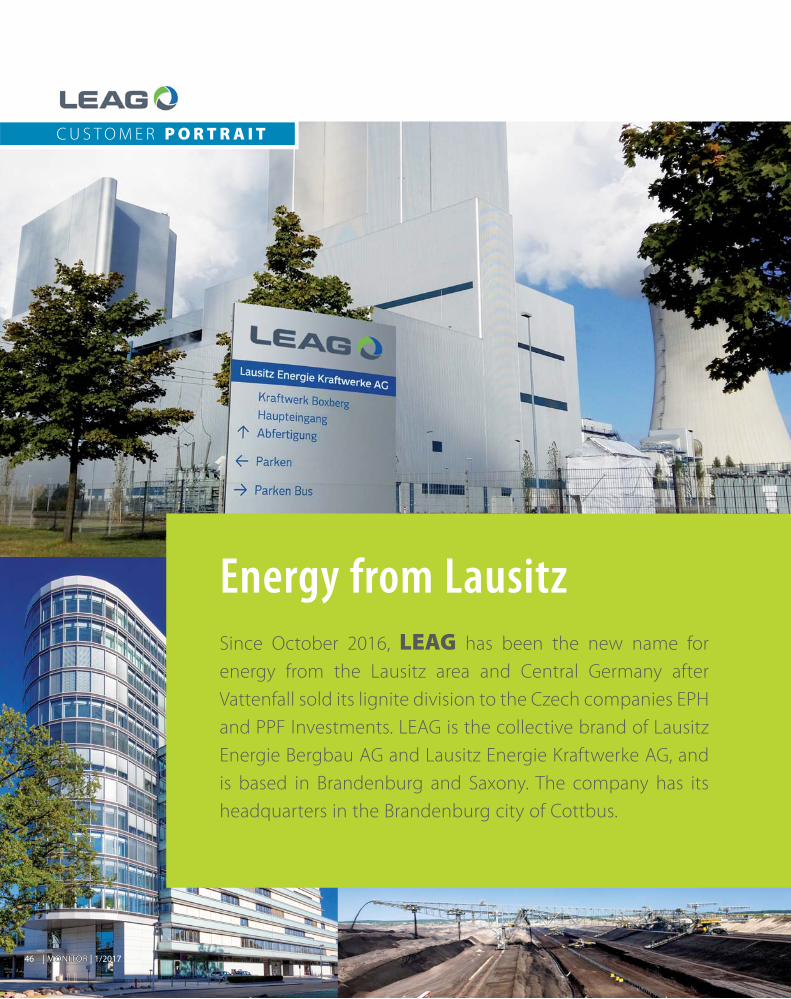
| MONITORMONITOR | 1/201746
Since October 2016, LEAG has been the new name for
energy from the Lausitz area and Central Germany after
Vattenfall sold its lignite division to the Czech companies EPH
and PPF Investments. LEAG is the collective brand of Lausitz
Energie Bergbau AG and Lausitz Energie Kraftwerke AG, and
is based in Brandenburg and Saxony. The company has its
headquarters in the Brandenburg city of Cottbus.
Energy from Lausitz
C U S T O M E R P O R T R A I T

1/2017 | MONITORMONITOR | 47
„Für Verpackungsaufgaben stellt MULTIVAC
flexible und intelligent konzipierte Lösungen bereit.”
At the same time, the timely recultivation of the surface mines creates a secure and sustainable post-mining landscape with a variety of options for application. Here LEAG supports, for example, the forest conver-sion programme of the state forest – with the aim of establishing a bio-diverse mixed forest landscape in the Lausitz region. More than 30 million trees have already been planted on surface mine sites.
In addition, we have witnessed the development of agricultural land as a source of income, ecologically valuable areas for nature conservation and mining lakes such as the Cottbuser Ostsee in the former Cottbus-Nord surface mine.
The LEAG company, Lausitz Energie Bergbau AG, is responsible for the four surface mines in Lausitz which see around 60 million tonnes of brown coal extracted annually. Lausitz Energie Kraftwerke AG is responsible for the power plant complex. The four power plants generate about 10 % of the kilowatt hours of electricity consumed in Germany. LEAG produces high-quality fi n-ishing products from fi ve to ten percent of the extracted brown coal.
Employment and training
Around 8,000 people are employed in the surface mines, power plants and refi nement areas, not to men-tion other company departments such as administra-tion, technical services and central railway operations. This makes LEAG the biggest energy company in the eastern part of Germany and one of the largest private employers in the region. Close to 700 young people are learning their trades in the training centres in Lausitz and at the power plant site in Lippendorf where eleven different apprenticeships are offered.
Economic strength and added value
The two LEAG companies not only offer a bright future to many young people in the region through their apprenticeship programmes, but with their business activities – order volumes of approx. EUR 900 million for over 3,300 suppliers – they also provide employment in the industrial sector and service industry – both in the environs of the LEAG sites and across the country.
"LEAG produces high-quality finishingproducts from five to ten percent of the extracted brown coal."
Opencast mine Nochten: bucket-chain dredger

| MONITORMONITOR | 1/201748
Electricity and heat – fl exible and safe
The annual electricity production from the power sta-tions is suffi cient to meet the constant needs of more than 15 million households. In addition to electricity, the power stations also generate district heating for Leipzig and the Lausitz cities of Cottbus, Spremberg, Weißwasser and Hoyerswerda, among others. Process steam is also supplied to industrial customers.
By shutting down old facilities and by investing bil-lions in the optimisation of new and existing sites, the company has been able to reduce its CO2 emissions or carbon footprint by 45 % since 1990. Brown coal covers around one quarter of the overall demand for electricity in Germany. Here, power stations can react
fl exibly to fl uctuations in energy production from renewable energies and thus have a sta-bilising infl uence on the supply system.
LEAG Kommunikation Cottbus
INFOProduction results of 2016
Raw coal mining in millions of tonnes
Surface mine in Jänschwalde 10,0Surface mine in Welzow-Süd 23,8Surface mine in Nochten 14,8Surface mine in Reichwalde 13,7
Total: 62,3
Net power generation in billions of KWh
Power station in Jänschwalde 20,3Power station in Boxberg 17,6
Power station in Schwarze Pumpe 11,4
Power station in Lippendorf (LEAG portion) 5,6
Total: 54,9
”Brown coal, as a local energy source, ensures a reliable supply of
energy at an affordable price.”
For more than 20 years, the transformer stations of LEAG’s drainage operation (formerly Vattenfall) have been equipped with insulation monitoring devices from Bender GmbH & Co. KG. By now, 200 of such devices are in use. Those responsible in the company praise the quality and reliability of this equipment.
20 to 30 drainage wells – out of 2,000 in total – are supplied with energy by a transformer station (with blue door in background).
C U S T O M E R P O R T R A I T
1/2017 | MONITORMONITOR | 49
EXHIBITIONS 2017
EXHIBITIONS NATIONAL
Hannover Messe24. – 28.04.2017Hanover
EVS – 30th International Electric Vehicle Symposium & Exhibition09. – 11.10.2017Stuttgart
eMove360° Europeelectric – connected – autonomous 17. – 19.10.2017Munich
SPS/IPC/DRIVES28. – 30.11.2017Nuremberg
RAILTEXBooth H9109. – 11.05.2017Birmingham, Great Britain
Global Electric Power Tech 2017Booth H125 (Wonnlee Solutions, South Korea)10. – 12.05.2017Seoul, South Korea
Smart Cities India 2017 Expo10. – 12.05.2017New Dehli, India
Sajam tehnikeBooth BEKER d.o.o15. – 19.05.2017Belgrad, Serbia
EXPONOR – Mining Trade Show15. – 19.05.2017Antofagasta, Chile
The Future of Operating Theatres Conference23.05.2017Manchester, Great Britain
8th Annual National Electric Mobility Canada 29.05. – 01.06.2017Markham, Ontario Canada
Electric Hybrid Marine06. – 08.06.2017Amsterdam, Netherlands
SUISSE PUBLIC13. – 16.06.2017Bern, Suisse
AUTOMATISA – Automation Trade Show14. – 16.06.2017Bogota, Colombia
POWER Sri Lanka 201714. – 16.07.2017Colombo, Sri Lanka
Offshore EuropeBooth: 3E15505. – 08.09.2017Aberdeen, Great Britain
Ineltec 201712. – 15.09.2017Basel, Suisse
Canadian Healthcare Engineering Society National Conference and Exhibition (CHES2017) 17. – 19.09.2017Niagara Falls, Ontario Canada
RAILTEX
EXHIBITIONS INTERNATIONAL
Elektrotechniek26. – 29.09.2017Utrecht, Netherlands
Medicall 201706. – 08.10.2017Mumbai, India
Healthcare Estates Booth: F7310. – 11.10.2017Manchester, Great Britain
KORMARINE 2017Booth: 5W1110. – 11.10.2017Busan, South Korea
Busworld Europe20. – 25.10.2017Kortrijk, Belgium
EUROPORT – Exhibition for maritime technology07. – 10.11.2017Rotterdam, Netherlands
FISEElectrical trade-show27.11. – 01.12.2017Medellin, Colombia
Intersolar India 201705. – 07.12.2017Mumbai, India
Electric Networks05. – 08.12.2017Moscow, Russia

| MONITORMONITOR | 1/201750
Ralf Muswieck Market Segment Manager Manufacturing | Sales Europe & MEA of Bender
I N T E R V I E W
Mr Muswieck, what tasks do you have as a Market
Segment Manager in the engineering sector?
I'm already familiar with this kind of sales support from
other companies. I am convinced that it is useful when
a company focuses on the industries in which it sees
potential.
The requirements on the components and therefore the
manufacturers are becoming more and more complex.
Customers therefore expect a certain understanding of
their requirements on the supplier side. They want to
speak with someone who understands them immediate-
ly, without having to explain too much.
The manufacturing market segment is all about
protection and monitoring technology for mechani-
cal engineering and industrial manufacturing.
What does this specifi cally mean for your area?
The task of the market segment manager, therefore, is
to fi rstly determine and collate the characteristics of the
relevant industry and its demands on our components.
Secondly, it is my job to make this information concerning
demand and requirements available to Sales, for example
as an argumentation guideline. Finally, Sales is involved
with all segments that are in focus at Bender. Within
these segments, all requirements of our devices may
be quite similar, but the core theme of the segments are
sometimes completely different. And this relates to the
intellectual interface between the customer's machine
and our device level. We want to help our colleagues in
Sales to adapt more swiftly to customer issues. This not
only assists us, but also the customer.
This requires not only a regular exchange with
colleagues, but also dialogue with the customer,
right?
Yes, as a link between the market and Bender for both
customer visits as well as trade fairs and conventions, I
fi nd out more about the needs of the market, observe
trends, collect ideas and I am thereby able to fi lter in
which areas Bender can optimise in the future, and which
market requirements Bender products can possibly be
adjusted to.
CAREER OUTLINE
Ralf Muswieck, born 1967, was born and raised in Lower Saxony.
After studying electrical engineering/communications engineering, he today looks back on 20 years
of experience in the fi eld of automation in mechanical and plant construction: He worked from 1996
to 2000 as an Application Engineer at OMRON GmbH (controllers, sensors, drive technology), and as
a Sales Engineer from 2000 to 2016 in various companies, always with a focus on controls, sensors
and drive technology.
He has been employed as a Market Segment Manager of the Manufacturing department at Bender
since February 2016.
Preventing unplanned plant downtimes with Bender systems
High Availability and Industry 4.0

51
What important demands are made
on the manufacturing plants of today?
A major issue is the high availability. Only a machine
that is actually producing, makes money. There are two
aspects to consider here: Firstly, production facilities and
equipment must be constructed in accordance with the
applicable standards in order to ensure the necessary
personnel and equipment safety. In many cases, the stand-
ards require that the system is switched off when an error
occurs. The result: An unplanned system downtime. Our
devices can help prevent a shutdown due to insulation
faults, by already reporting small changes in fault currents
and insulation resistance before it must be switched off.
The current standards for equipment, such as the current
draft of DIN EN 60204-1 (VDE 0113-1):2014-10 provides,
are moving increasingly towards the use of insulation mon-
itoring in IT systems that reports instead of switching off.
The background is that a shutdown in complex production
processes, for example, paper, glass and steel, not only
leads to a production stop, but can also cause expensive
damage to the equipment. This issue is very opportune for
the demand for high availability.
Secondly, the powerquality is suffering due to the cur-
rently widespread electronic loads. Strong voltage fl uctu-
ations, for example, can destroy electrical components,
which would result in a system downtime. In this regard,
there is the standard DIN EN 50160:2010, which defi nes
and specifi es the essential features of the mains voltage
at the mains connection point under normal operating
conditions that can be monitored.
What current issues result from this?
In production plants, periodic verifi cation is currently a topic
that was brought back into focus by the accident prevention
regulations DGUV provision 3, formerly BGV A3, of the trade
association.
It is stated in the standards and regulations, such as DIN
VDE 0105-100 (VDE 0105-100):2015-10, that the insulation
resistance of electrical installations must be measured reg-
ularly. But the system must be shut down for measuring the
insulation resistance.
However, the standards also say that you can avoid recur-
rent measuring in a shut-down state of the system by
continuously monitoring fault currents with measurement
technology and an appropriate management system.
Are there any current developments in the industry?
The topic Industry 4.0, i.e. digitisation, is currently very popular
in the segment. On my tours through various mechanical engi-
neering trade fairs, no matter in which industry, you can see the
subject stated on at least every second stand.
Industry 4.0 means the interlocking of industrial
production with modern information and communication
technology? What are the requirements and objectives
for this purpose?
The technical basis for this is intelligent and digitally networked
systems. With their help, largely self-organised production
should be possible: People, machines, systems, logistics and
products communicate directly with each other in Industry 4.0.
It is increasingly important that as much data as possible is
recorded in a production plant. Firstly for production planning,
but also for maintenance. After preventive maintenance, sta-
tus-based maintenance is now sought.
What is the difference between preventive
and status-based maintenance?
Preventive maintenance has two major drawbacks. Firstly, you
replace components which are still relatively good. Secondly, you
have no guarantee that the newly installed component will hold
until the next maintenance.
With status-based maintenance, however, you have the major
components permanently in sight using corresponding sensor
and measuring technology. Their measured values are evaluated
by corresponding algorithms to instantly detect anomalies that
may indicate an imminent failure.
How can Bender products help here?
Regardless of the topic of Industry 4.0, our systems always provide
the advantage that errors are signalled before the machine needs
to be shut down. This allows condition monitoring to be realised,
which is the prerequisite for status-based maintenance. Our sys-
tems capture the insulation resistance and the residual currents
online and permanently.
They immediately report to the operator when something is
wrong, before a protective device unit shuts down. Therefore, the
maintenance employees have enough time to plan and prepare a
repair. They therefore have a time advantage - as opposed to an
unplanned machine downtime.
1/2017 | MONITORMONITOR |
"It is increasingly important
that as much data as possible is recorded
in a production plant."
Michaela Heck M.A., textwerk-heck
Herr Muswieck, thank you for this informative interview.

| MONITORMONITOR | 1/2016
What you should know about measuring current transformers
Bender
Measuring current transformers
What is a current transformer?A current transformer is a special transformer designed to proportionally convert primary currents with a large amperage to directly measurable, smaller secondary currents. Conditional on its design as well as its physical operating principle, a safe galvanic separation between primary circuit and measuring circuit is achieved.
What is a residual current transformer?The residual current transformer measures the vectorial sum of all phase currents that fl ow through the transform-er core. The current that fl ows in must also fl ow out again. If this sum is not zero, then the result is a residual current that the residual current transformer measures. As a rule, residual currents can only be measured very inaccurately with "normal" transformers.
What is a "burden" for current transformers?The "burden" is an impedance, expressed in ohms, that is connected to the secondary circuit of the current transformer.
Can a current transformer on the secondary circuit be dangerous?Yes, when operating the current transformer with an open secondary circuit, contact voltages that are dangerous for persons can occur at the secondary terminals. A single-pole earthing of the secondary circuit protects against this.
Can a current transformer be destroyed during normal operation?Yes, it can be destroyed when a secondary circuit is "open". Before replacing measuring devices in the secondary cir-cuit of the current transformer, it must be short-circuited at its secondary connections.
521/2017 | MONITORMONITOR |
Captions:
PracticalPage A
Expertise
Split-core-type current transformer AC
Measuring range up to 500 A
Additional devices required – No
Bus system compatible – No
Supply voltage – No
Window-type current transformer AC
Measuring ranges up to 1000 A
Additional devices required – No
Bus system compatible – No
Supply voltage – No
Rogowski coil AC
Measuring range 100 mA … 20 A
Additional devices required – Yes
Bus system compatible – No
Supply voltage – Yes
Note: Rogowski coil & signal
converters are calibrated to
each other
Window-type current transformer AC and DC
a) Measuring range 10 mA … 10 A Additional devices required – Yes Bus system compatible – No Supply voltage – DC +12 V Note: Max. cable length 10 m
b) Measuring range 100 μA … 500 mA Additional devices required – Yes Bus system compatible – Yes Supply voltage – DC 24 V Note: Max. cable length 1200 m
a)
b)
–

| MONITOR | 1/2016
531/2017 | MONITORMONITOR |
Can current transformers be calibrated?
Yes, the PTB (Physikalisch Technische Bundesanstalt, the German National Metrology Institute) calibrates current transformers (only relevant for current transformers that are used for billing purposes). Calibration is not required for residual current transformers.
What is understood by rated transformation (transformation ratio)?The ratio of the primary rated current to the secondary rated current. The rated transformation ratio of a cur-rent transformer is indicated on the rating plate as an unabridged break. x / 5 A transformers are most frequent-ly used, most evaluators have the higher accuracy class at 5 A. For technical, but above all, for economic reasons, x / 1 A transformers are recommended for long lengths of measuring line. The line losses are only 4 % compared to 5 A transformers. However, the measuring devices fre-quently have the lower measuring accuracy here.
Is a very accurate transformer needed for the PQ measurement?No, you do not need a particularly accurate measuring current transformer for the power quality measurement, since the consideration in accordance with EN 50160 is purely a voltage consideration. The current distortions are not required in the EN 50160 report, even though it would indicate precisely whether the measured system is the disturbing station or whether the problem is external.
Instructions for choosing the measuring current transformer:The smallest possible measuring current transformer should be used to minimise interference to the transformer. The best choice is a current transformer with a high accuracy class. As a rule, this is always a bar-type current transformer.
Ic
Oliver SchultzApplication Sales
What must be taken into consideration when feeding cables through a current transformer?
A&B) The lines/conductors must be centred in the middle of the measuring current transformer.
C) A bend of the line/conductor may be carried out only at a certain distance from the transformer.
D) A braided shield must not be fed through the transformer!
A B
C
Bender Measuring current transformers
PracticalPage B
Expertise
D

1/2017 | MONITORMONITOR |
Bender GmbH & Co. KG
Londorfer Str. 65 • D-35305 Gruenberg / Germany
Fon: +49 6401 807-0 • Fax: +49 6401 807-259
E-Mail: [email protected] • www.bender.de
The Bender Group with its main offi ce in Gruenberg/Hesse
has 70 representations and 14 subsidiaries with nearly
700 employees worldwide.
You can fi nd your regional contacts at www.bender.de.